FUN Piccolo def 69001-0503.cdr - Ikarus.net
FUN Piccolo def 69001-0503.cdr - Ikarus.net
FUN Piccolo def 69001-0503.cdr - Ikarus.net

You also want an ePaper? Increase the reach of your titles
YUMPU automatically turns print PDFs into web optimized ePapers that Google loves.
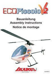
<strong>FUN</strong> <strong>Piccolo</strong><br />
Bauanleitung<br />
Building Instructions<br />
Notice de montage<br />
Norbert Grüntjens<br />
www.ikarus.<strong>net</strong><br />
<strong>69001</strong>-0503
Einführung<br />
2<br />
Danke...<br />
für den Kauf des revolutionären <strong>FUN</strong> <strong>Piccolo</strong>. Mit dem<br />
<strong>FUN</strong> <strong>Piccolo</strong>, einem brandneuen R/C-Elektro-<br />
Modellhelicopter auf dem letzten Stand der Technik,<br />
wird Indoor Flying zum praktischen Vergnügen. Die<br />
Verwendung modernster Technologien und neuester<br />
Produktionsprozesse bietet hervorragende Leistung und<br />
beste Flugzeiten selbst mit einer einfachen Vierkanal-<br />
Fernsteuerung. Die ausgiebige Verwendung von Kohlefasermaterialien<br />
ermöglicht ein überraschendes Leistungs-<br />
/Gewicht-Verhältnis und macht den <strong>Piccolo</strong> auch zu einem<br />
Outdoor-Helicopter für ruhigere Windverhältnisse..<br />
Dieses Produkt wurde bei uns geprüft und sorgfältig verpackt.<br />
Bitte prüfen Sie trotzdem gleich, ob dieser Bausatz komplett<br />
und unbeschädigt ist. Haben Sie bitte Verständnis dafür, daß<br />
wir spätere Reklamationen nicht berücksichtigen können.<br />
Sorgfalt...<br />
ist sehr wichtig beim Bau dieses Hubschraubers. Von<br />
geschickten Händen gebaut und geflogen, bietet er viel Spaß<br />
und Befriedigung. Allerdings ist er kein Spielzeug und muß mit<br />
Sorgfalt und Verantwortung zusammengebaut und mit<br />
Rücksicht auf andere Personen betrieben werden.<br />
Diesen Modellhelicopter zu fliegen ist nicht allzu schwer,<br />
erfordert jedoch etwas Geduld und Übung.<br />
Sind Sie ein Neuling im Modellhelicopterbereich, so ist es<br />
empfehlenswert, den Rat des örtlichen Modellbau-Clubs, von<br />
erfahrenen Bekannten oder Ihres Händlers vor Ort<br />
einzuholen. Reklamationen aufgrund von unsachgemäßer<br />
Behandlung oder Schadensersatzforderungen aufgrund<br />
mißbräuchlicher Anwendung dieses Modelles müssen wir<br />
zurückweisen, da der praktische Betrieb außerhalb unseres<br />
Einflußbereiches liegt.<br />
Hubschrauber unterliegen diversen physikalischen Gesetzen,<br />
und der Grat zwischen Erfolg und Mißerfolg ist oft<br />
schmal. Der <strong>Piccolo</strong> ist das Ergebnis unserer Erfahrung, einer<br />
aufwendigen Entwicklung und zahlreicher Tests. Die Montage<br />
liegt jetzt bei Ihnen. Dieses Handbuch soll Ihnen dabei in jeder<br />
Weise helfen. Bitte folgen Sie genau allen Schritten und<br />
beachten Sie die Hinweise exakt.<br />
Montieren Sie das Modell so sorgfältig wie möglich.<br />
Machen Sie im Zweifel eine Pause, überdenken das<br />
Problem oder fragen einen erfahrenen Modellflieger um<br />
Rat. Es wird sich auszahlen.<br />
Garantie...<br />
Wir garantieren, für eine Zeit von 6 Monaten nach dem Kauf,<br />
daß dieser Bausatz frei von Fabrikations- oder Materialfehlern<br />
ist. Schäden durch falschen Gebrauch oder Montagefehler<br />
werden durch diese Garantie nicht gedeckt. Sobald der<br />
Hubschrauber in Betrieb genommen wird, übernimmt der<br />
Benutzer alle daraus erwachsende Verantwortlichkeit.<br />
Sie benötigen...<br />
(Nicht im Bausatz enthalten)<br />
Bordelektronik (Empfänger, zwei Motorregler, Gyro und die<br />
elektronische Mischung, alles in einer Baugruppe)<br />
Teil Best. Nr.: Beschreibung<br />
35 Mhz 720635 IKARUS Piccoboard<br />
40/41 Mhz 720640 IKARUS Piccoboard<br />
72 Mhz 720672 IKARUS Piccoboard<br />
Servos 171201 Pico Servo (2x)<br />
Teil: Best. Nr.: Beschreibung:<br />
Batterien: 67492 8 Zellen NiMh Akku<br />
Sender: 173506 35Mhz .4-6 Kanal<br />
174006 40/41Mhz<br />
177206 72Mhz<br />
Ladegerät: 67489 für 4-10 Zellen<br />
Abmessungen:<br />
Hauptrotor-Durchmesser: 520 mm<br />
Rumpflänge: 500 mm<br />
Fluggewicht: ca. 280 g<br />
Werkzeuge:<br />
Zur Montage benötigen Sie zusätzlich<br />
- Ein Bastelmesser oder scharfes Messer<br />
- Schalen zur Ablage von Kleinteilen<br />
- Eine kleine Spitzzange<br />
- Eine kleine Schere (z.B. Nagelschere)<br />
Symbole...<br />
Um Ihre Aufmerksamkeit auf bestimmte Vorgänge zu lenken,<br />
haben wir Symbole benutzt, die folgende Bedeutung haben:<br />
Hier ist besondere Sorgfalt nötig<br />
Verwenden Sie Cyanacrylat- (CA-) Kleber<br />
WARNHINWEIS!:<br />
Cyanacrylat (CA)-Kleber klebt innerhalb von Sekunden Haut<br />
und Augen zusammen. Bei Augenkontakt sofort mit Wasser<br />
spülen, Arzt aufsuchen. Darf nicht in die Hände von Kindern<br />
gelangen. Dampf nicht einatmen. Nur in gut belüfteten<br />
Bereichen verwenden.<br />
Allgemeines:<br />
Dieser Hubschrauber ist schon aufgrund seiner Größe etwas<br />
Besonderes. Die Einzelteile sind gewichtsoptimiert und daher<br />
mit Vorsicht zu behandeln.<br />
Folgen Sie der Anleitung bitte Schritt für Schritt. Prüfen Sie vor<br />
jedem Bauabschnitt die benötigten Teile auf etwaige<br />
Angußgrate und entfernen Sie diese vorsichtig mit einem<br />
scharfen Messer und Schleifpapier.<br />
Beachten Sie die Hinweise zum Justieren immer sofort.<br />
Spätere Nacharbeiten sind oft unnötig kompliziert.<br />
Bei Verklebungen reicht sehr wenig CA-Kleber aus, zuviel<br />
Klebstoff erschwert nur eine gute Verklebung. Desweiteren<br />
hat CA-Kleber die Eigenschaft, in enge Spalten zu fließen,<br />
arbeiten Sie damit also bitte immer sparsam und sorgfältig!<br />
Alle Schrauben im Baukasten sind gewichtsoptimiert und<br />
daher möglichst klein dimensioniert. Nehmen Sie also bitte<br />
alle Verschraubungen mit Feingefühl vor. Die Motoren<br />
beispielsweise dürfen sich von Hand nicht mehr bewegen<br />
lassen, aber ein zu starkes Anziehen führt zur Zerstörung der<br />
Gewinde!
Einführung Glossar<br />
Verarbeitung des CA-Klebers:<br />
Voraussetzung für eine einwandfreie Verklebung sind<br />
saubere und trockene Klebeflächen. Deshalb sollten<br />
grundsätzlich Staub-, Öl-, Fett- oder Trennmittelreste von den<br />
Klebeflächen entfernt werden. Je nach Material und Auftragsmenge<br />
des Klebstoffs erreicht man die sog. Handfestigkeit<br />
des Klebstoffs nach einigen Sekunden bis wenigen Minuten.<br />
Die Endfestigkeit erreicht man nach ca. 12 Stunden.Da CA-<br />
Klebstoff Luftfeuchtigkeit zum Aushärten benötigt, beschleunigt<br />
das Anhauchen der Klebestelle die Aushärtung. Zu<br />
trockene Luft kann das Aushärten um Minuten verzögern.<br />
Cyanacrylat-Klebstoff härtet in Sekundenschnelle unter dem<br />
Einfluß der Luftfeuchte, bzw Feuchtigkeit auf den Klebestellen<br />
aus. Deshalb ist Vorsicht geboten beim Verarbeiten,<br />
insbesondere bei Haut- oder Augenkontakt. Bei Hautkontakt,<br />
z. B. wenn die Finger zusammengeklebt sind, mit Seifenwasser<br />
oder Handwaschpaste reinigen (evtl. Handbad in<br />
warmer Seifenlauge). Eine andere Möglichkeit ist, die zusammengeklebten<br />
Finger in warmem Wasser zu reiben und eine<br />
Büroklammer oder einen Draht zwischen die Finger zu<br />
schieben. Nach einiger Zeit lösen sich die Finger wieder.<br />
Außerdem können die betroffenen Stellen sofort mit Aceton,<br />
ersatzweise Nagellackentferner behandelt werden. Falls<br />
Klebstoffreste zurückbleiben kann man diese mit Bimsstein<br />
abrubbeln.<br />
Gelangen Spritzer in die Augen oder den Mund, diese<br />
unbedingt offen halten und mit reichlich Wasser spülen. Falls<br />
noch notwendig, anschließend Arzt aufsuchen.<br />
CA-Sekundenkleber ist weder giftig noch anderweitig<br />
gesundheitsschädlich. Wegen des Eigengeruchs von CA-<br />
Klebstoff ist es ratsam, bei Verarbeitung größerer Mengen<br />
den Arbeitsplatz gut zu belüften.<br />
Unter bestimmten Bedingungen kann es zum sog.<br />
„Ausblühen“ des Klebers kommen. Dies macht sich als<br />
weißlicher Niederschlag neben der Klebestelle bemerkbar.<br />
Sie können diesen mit etwas unverdünntem Essig- oder<br />
Citrusreiniger aus dem Haushalt entfernen.<br />
Lagerung des CA-Klebers:<br />
CA-Klebstoff ist nicht unbegrenzt haltbar. Die Packung sollte<br />
nach Gebrauch verschlossen und möglichst kühl, z. B. im<br />
Kühlschrank, aufbewahrt werden.<br />
IKARUS WÜNSCHT IHNEN VIEL SPASS UND<br />
FREUDE BEIM BAUEN UND FLIEGEN DES<br />
<strong>FUN</strong> - PICCOLO<br />
Für Neulinge im Bereich des Modellhubschraubers<br />
wollen wir zunächst einige Fachausdrücke und etwas<br />
Theorie erklären.<br />
Die Mechanik<br />
ist die Summe aller Komponenten um das Chassis des<br />
Hubschraubers, incl.Antriebsmotor, Hauptgetriebe, Rotorwelle<br />
und Kufen (s. S. 9 ).<br />
3<br />
Die Taumelscheibe<br />
besteht aus dem Außenring, einem Kugellager und dem<br />
Innenring. Der Außenring wird von Servos angesteuert und<br />
dreht sich nicht, der kugelgelagerte Innenring dreht sich mit<br />
dem Rotor. Erfolgt ein Steuersignal, so verkippt der Außenring<br />
und damit die Ebene der Taumelscheibe. Der Innenring gibt<br />
dann die Steuersignale an den Hauptrotor weiter. Dabei wirkt<br />
es so, als ob der Innenring „taumelt“, daher der Name<br />
Taumelscheibe.<br />
Der Hauptrotor<br />
ist das zum Fliegen und Steuern wichtigste Element. Dazu<br />
gehören auch die Rotorblätter und die Hillerpaddel.<br />
Die Rotorblätter<br />
erzeugen den Auftrieb, den der Hubschrauber zum Fliegen<br />
braucht. Der <strong>FUN</strong> <strong>Piccolo</strong> ist drehzahlgesteuert, d.h. die<br />
Rotorblätter haben einen festen Anstellwinkel und der Auftrieb<br />
wird über die Drehzahl des Rotors verändert, höhere<br />
Drehzahl z.B. bedeutet steigen.<br />
Die Hillerpaddel<br />
dienen der Stabilisierung und der Steuerung des Hubschraubers.<br />
Sie werden über den Innenring der Taumelscheibe,<br />
die Steuerstangen und die Anlenkhebel verstellt.<br />
Befestigt sind Sie an der Stabistange.<br />
Der Heckrotor<br />
sitzt hinten am Hubschrauber und wirkt quer zur Flugrichtung.<br />
Auch er ist beim <strong>FUN</strong> <strong>Piccolo</strong> drehzahlgesteuert und besitzt<br />
einen eigenen Antriebsmotor..<br />
Die Servos<br />
sind kleine Getriebe, die die elektronischen Steuersignale in<br />
mechanische Bewegungen umsetzen und die Taumelscheibe<br />
ansteuern. Beim <strong>Piccolo</strong> sind es zwei Servos, die nach der<br />
jeweils gesteuerten Funktion benannt werden, z. B. das<br />
Nickservo für die Nickfunktion.<br />
Die Regler<br />
steuern die Drehzahl der beiden Antriebsmotoren, indem sie<br />
ihnen mehr oder weniger Spannung zuteilen. Die Regler<br />
befinden sich auf dem Piccoboard.<br />
Der Empfänger<br />
fängt über seine Antenne die Funksignale des Fernsteuersenders<br />
auf und gibt sie über das Piccoboard an die Servos<br />
oder Regler weiter.<br />
Der Kreisel<br />
ist eine Stabilisierungshilfe, die den Heckrotor beeinflußt. Er<br />
dämpft schnelle Drehungen um die Hochachse und vereinfacht<br />
das Fliegen deutlich.<br />
Der Mischer<br />
kombiniert in diesem Fall die Drehzahl von Haupt- und<br />
Heckrotor. Er sorgt so dafür, daß beim Steigen oder Sinken
Glossar<br />
4<br />
der Hubschrauber nicht wegdreht. Mischer, Kreisel,<br />
Regler und Empfänger sind im Piccoboard zu einer<br />
Einheit zusammengefaßt.<br />
Grundlagen<br />
Wie fliegt ein Hubschrauber ?<br />
Der Hubschrauber erzeugt seinen zum Fliegen nötigen<br />
Auftrieb durch rotierende Flügel, die Rotorblätter. Dieser<br />
Rotor wird durch einen Motor angetrieben und erzeugt dadurch<br />
ein Drehmoment, der Hubschrauber will sich um die<br />
Hochachse drehen. Dem wirkt nun der Heckrotor entgegen,<br />
indem er mit seitlichem Schub diese (ungewollte) Drehung<br />
verhindert, andererseits aber gewollte Drehungen durch<br />
Ändern seines Schubs ermöglicht.<br />
Damit haben wir auch gleich zwei Funktionen, um den<br />
Hubschrauber zu steuern, kennengelernt: Das Steigen und<br />
Sinken beeinflussen wir über den Auftrieb, also die Drehzahl<br />
des Hauptrotors und Drehungen um die Hochachse steuern<br />
wir über den Schub, also auch hier die Drehzahl des<br />
Heckrotors.<br />
Das reicht uns aber noch nicht, wir müssen den Hubschrauber<br />
ja auch vorwärts, rückwärts (Nickfunktion) und<br />
seitwärts (Rollfunktion) steuern können.<br />
Diese Funktionen können wir nicht direkt sondern nur über<br />
einen kleinen Umweg steuern, und dabei helfen uns die<br />
Hillerpaddel. Ihr Anstellwinkel wird durch die Servos über die<br />
Taumelscheibe zyklisch, d. h. regelmäßig wiederkehrend,<br />
verändert, so daß sich zuerst die Drehebene der Hillerpaddel<br />
und dann die des Hauptrotors schräg stellt, und zwar parallel<br />
zur Stellung der Taumelscheibe. Neigt man also die<br />
Taumelscheibe nach vorne, so neigt sich auch die Hiller- und<br />
die Hauptrotorebene nach vorne. Dies bewirkt, daß der<br />
Auftrieb des Rotors nicht mehr senkrecht nach oben, sondern<br />
ein bißchen nach vorne zeigt, und damit setzt sich unser<br />
Hubschrauber auch nach vorne in Bewegung. Gleiches gilt<br />
analog für die Seit- und Rückwärtsbewegung.<br />
Wir haben also vier direkte Steuerfunktionen und die<br />
brauchen wir auch alle, denn der Hubschrauber hat,<br />
besonders im Schwebeflug, auch diese vier Freiheitsgrade<br />
wie folgt:<br />
- 3 Bewegungen (Translationen), Auf-/ Abwärts, Vor- / Rückwärts<br />
und Seitwärts<br />
- 1 Rotation, und zwar die Drehung um die Hochachse<br />
An Steuerhilfen gibt es nur eine, und zwar die Stabilisierung<br />
der Hochachsendrehung mit Hilfe eines Kreisels. Dieser wirkt<br />
Drehungen durch Änderung des Schubs am Heckrotor<br />
entgegen und sorgt dafür, daß der Hubschrauber keine<br />
plötzlichen Bewegungen um die Hochachse macht.<br />
Aber bis zum Fliegen dauert es noch ein wenig,jetzt werden<br />
wir zunächst auf die Montage des Fun <strong>Piccolo</strong> eingehen.<br />
Bedenken Sie dabei immer, daß dieser Hubschrauber ein<br />
Leichtgewicht ist. Seien Sie sparsam mit Klebstoff und vor<br />
allem mit Klebeband.<br />
Jedes Gramm Gewicht mehr am Hubschrauber kostet ca. 5<br />
Grundlagen<br />
Sekunden Flugzeit, achten Sie daher bitte darauf, leichte<br />
Bauteile, wie z. B. unser Piccoboard, einzusetzen und - wo<br />
immer möglich- Gewicht zu sparen.<br />
Der Zusammenbau<br />
Die Mechanik<br />
Rauhen Sie zunächst alle Klebestellen mit Schleifpapier<br />
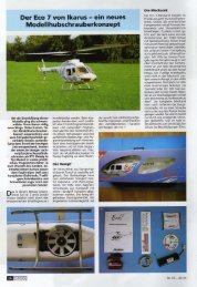
etwas auf. Kleben Sie dann zuerst die hinteren Streben 1. in<br />
die Aufnahmen am Chassis. Ist die Klebung getrock<strong>net</strong>,<br />
werden die vorderen Streben 2. von unten ins Chassis geschoben<br />
und so positioniert, daß Sie ganz außen an der Wand<br />
sitzen und parallel zu den hinteren Streben sind. Erst dann<br />
wird CA-Kleber zugegeben. Kleben Sie anschließend die<br />
Kufen 3. auf die Streben. Zuletzt wird die Kabinenhalterung<br />
Nr. 67380 mittig auf das Chassis geklebt.<br />
3.<br />
67380<br />
2.<br />
67360<br />
67378<br />
67361<br />
67411<br />
Beachten Sie bitte die unterschiedlichen Längen der<br />
Kufenstreben. Durch den seitlichen Schub des Heckrotors<br />
ergibt sich beim Abheben eine Schrägstellung des Modelles.<br />
Die verschiedenen Längen kompensieren diese Schrägstellung<br />
und erleichtern den Start.<br />
3.<br />
86 mm<br />
67411<br />
1.<br />
Rückansicht<br />
80 mm<br />
67378
Die Mechanik<br />
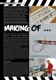
Schieben Sie das Hauptzahnrad Nr. 67372 auf die Rotorwelle<br />
und drücken Sie den kürzeren Stift Nr. 67399 mit einer Zange<br />
durch die Bohrungen von Zahnrad und Welle. Drücken Sie die<br />
beiden Kunstoff-Lager Nr. 69029 ins Gehäuse, schieben die<br />
Rotorwelle durch und fixieren sie von oben mit der U-Scheibe<br />
und der Gummitülle Nr. 67385.<br />
67385<br />
69029<br />
67631<br />
67399<br />
Drücken Sie das Ritzel (Standard 9 Zähne, Nr. 67373) auf die<br />
Motorwelle, bis Ritzel und Welle bündig abschließen.<br />
67401<br />
69029<br />
69022<br />
67373<br />
67372<br />
5<br />
Befestigen Sie den Motor mit den beiden Schrauben<br />
M2,6x5 und den U-Scheiben in den Langlöchern so,<br />
daß das Getriebe nicht zu stramm läuft, sondern ein<br />
wenig Spiel hat. Schieben Sie dazu einen Papierstreifen<br />
zwischen die Zahnräder, drücken den Motor nach<br />
hinten und ziehen zunächst die vordere, dann die hintere<br />
Schraube mit Gefühl an. Ziehen Sie danach den Papierstreifen<br />
heraus. Die leichtgängige Justierung ist für Flugzeit<br />
und Lebensdauer wichtig.<br />
Bevor Sie mit der Montage des Motors beginnen, sollten Sie<br />
den Motor einlaufen lassen. Dadurch können Sie die Lebensdauer<br />
und die Leistung deutlich verbessern. Sofern Sie nicht<br />
den Original-<strong>Ikarus</strong>-Empfänger verwenden, kann ein nicht<br />
eingelaufener Motor u.U., bedingt durch eine starke Funkenbildung,<br />
Störungen auf den Empfänger übertragen. Die Folge<br />
wäre ein zeitweises leichtes Zucken der Servos.<br />
67397<br />
67394<br />
Einlaufen des Motors:<br />
Nehmen Sie Ihre Fernsteuerungsanlage in Betrieb. Schalten<br />
Sie zunächst den Sender ein und stellen den Gasknüppel auf<br />
Leerlaufposition. Verbinden Sie den Motor mit dem<br />
Piccoboard. Stecken Sie dann einen geladenen Flugakku am<br />
Piccoboard ein. Nachdem die rote LED am Piccoboard<br />
aufleuchtet, geben Sie 1/4 Gas und lassen den Motor so (ohne<br />
Last) einlaufen, bis der Accu leer ist. Wiederholen Sie die<br />
Einlaufphase 2-3 mal.
Der Rotorkopf<br />
6<br />
Die Kugelclips sind die wichtigsten Verbindungselemente<br />
für die Steuerung des Hubschraubers. Sie<br />
sollen sich spielfrei, aber leichtgängig bewegen lassen.<br />
Aufgrund von Fertigungstoleranzen kann dies werksseitig<br />
nicht zufriedenstellend voreingestellt werden. Deshalb<br />
sind die Clipse von uns so ausgelegt, daß sie eher etwas zu<br />
schwergängig sind. Dies läßt sich nämlich, wie Sie sehen<br />
werden, schnell und einfach nachjustieren.<br />
Drücken Sie dazu einen Kugelclip auf die zugehörige Kugel.<br />
Dabei zeigt die scharfkantige Seite des Ringes um den Clip<br />
immer zur Kugel. Schwenken Sie ihn dann in alle Richtungen.<br />
Wenn Sie merken, daß sich der Clip nicht leichtgängig und<br />
ruckfrei bewegen läßt, dann drücken Sie mit einer kleinen<br />
Zange den Clip vorsichtig auf der Kugel zusammen. Fangen<br />
Sie bitte mit wenig Druck an, prüfen dann wieder die<br />
Beweglichkeit, drücken nochmal und so fort, bis sich der Clip<br />
leichtgängig schwenken läßt. Verfahren Sie so bitte<br />
nacheinander mit allen Kugelclips.<br />
Scharfkantig<br />
Gerundet<br />
Die Zuordnung, welcher Clip zu welcher Kugel gehört, können<br />
Sie der Abbildung unten entnehmen. Denken Sie daran, die<br />
scharfkantige Seite des Ringes am Clip zeigt immer zur Kugel,<br />
die abgerundete Seite weist nach außen.<br />
langer Arm<br />
kurzer Arm<br />
Die Taumelscheibe haben wir bereits vormontiert. Schieben<br />
Sie die Taumelscheibe Nr. 67364 auf die Rotorwelle Nr.<br />
69022S, stecken Sie das Zentralstück Nr. 67369 auf und<br />
drücken den längeren Stift Nr. 67400 mit einer Zange durch<br />
die Bohrungen von Welle und Zentralstück. Der Stift muß<br />
mittig im Zentralstück sitzen. Schieben Sie dann die<br />
Kunststoff-Lager Nr. 69028 auf das Zentralstück Nr. 67369.<br />
67364<br />
69028S<br />
67369<br />
67370<br />
69028<br />
69022<br />
67400<br />
Stecken Sie den Rotorkopf Nr. 67370 auf die Kunststoff-Lager,<br />
indem Sie von unten gegen die Lager und von oben auf die<br />
Bügel des Rotorkopfs drücken. Nach dem Einschnappen hat<br />
der Kopf auf den Lagern etwas Spiel, dies ist beabsichtigt.<br />
Biegen Sie den Taumelscheibenmitnehmer Nr. 67366 mit zwei<br />
Fingern vor, so daß er in etwa die abgebildete Form annimmt.<br />
Stecken Sie dann den Mitnehmer zunächst von oben auf den<br />
Stift, verbiegen ihn dann vorsichtig und stecken die andere<br />
Seite von unten auf. Clipsen Sie das Kugelgelenk an einen der<br />
kurzen Arme des Innenrings der Taumelscheibe. Die scharfkantige<br />
Seite des Clips zeigt dabei zur Kugel.<br />
67366<br />
Gerundet<br />
Scharfkantig
Der Rotorkopf<br />
Stecken Sie die Stabistange Nr. 67377 durch den Rotorkopf, schieben dann die Anlenkhebel Nr. 67368 auf und fixieren sie<br />
mit den Schrauben M2x6 Nr. 67561 so, daß die Stabistange mittig sitzt und die beiden<br />
Anlenkhebel in einer Ebene liegen. Achten Sie bitte darauf, daß sich die Stabistange<br />
leicht drehen läßt, aber ein kleinstmögliches Längsspiel hat. Falls die Stange zu<br />
schwer drehbar ist, schleifen Sie sie in der<br />
Stabistange<br />
67377<br />
Mitte vorsichtig etwas dünner.<br />
67368<br />
Stecken Sie die Hillerpaddel Nr. 67371 auf die Stabistange<br />
Nr. 67377, bis diese bündig mit der Außenseite der<br />
Befestigungslasche der Paddel ist und verschrauben Sie sie.<br />
Achten Sie bitte darauf, daß die Paddel zueinander und mit den Anlenkhebeln in einer Ebene liegen. Diese Einstellung nehmen<br />
Sie bitte mit viel Sorgfalt vor, sie ist wichtig für die Flugeigenschaften. Der Rotorkopf kann jetzt in den Kugellagern pendeln.<br />
Stellen Sie den Hubschraube gerade hin, und beobachten Sie die Hillerstange. Neigt sich immer dasselbe Paddel nach unten,<br />
so prüfen Sie nochmal, ob der<br />
Abstand zur Mitte auf beiden<br />
67371 Seiten gleich ist, und korrigieren<br />
67561<br />
Sie ihn gegebenenfalls. Bleibt die<br />
Unwucht, so kleben Sie<br />
etwas Tesafilm auf das<br />
Paddel, das sich hebt, bis<br />
beide genau in der Waage<br />
Hillerpaddel<br />
bleiben.<br />
67582<br />
67582<br />
Clipsen Sie die beiden Steuerstangen Nr. 67367 in die Aufnahmen der Anlenkhebel und auf die längeren<br />
Arme des Taumelscheibeninnenrings. Auch hier zeigt die scharfkantige Seite des Clips<br />
wieder zur Kugel.<br />
scharfkantig<br />
67561<br />
67367<br />
gerundet<br />
7
Der Heckrotor<br />
8<br />
Drücken Sie die beiden Kunststoff-Lager Nr. 69028 in das Heckrotorgehäuse Nr. 67362, schieben die Heckwelle Nr.<br />
69020 durch und montieren das Heckzahnrad Nr. 67363 und das Heckrotorblatt Nr. 67376 wie dargestellt. Die<br />
rechteckige Auflage des Heckrotorblatts sitzt paßgenau zwischen<br />
den Führungsnasen des Zahnrads und wird von diesen<br />
mitgenommen. Zum Schluß wird alles mit den Schlauchstücken<br />
67376<br />
fixiert, indem diese an den beiden Enden der Welle<br />
übergeschoben werden.<br />
Achtung: Das Heckrotorblatt kann produktionsbedingt<br />
scharfe Kanten besitzen. Schleifen Sie die Kanten<br />
vorsichtig etwas ab.<br />
67391<br />
67388<br />
67376<br />
Das Heckrotorblatt ist jetzt frei drehbar. Halten Sie das Gehäuse so, daß die Heckrotorwelle waagrecht ist und beobachten<br />
Sie, ob immer dieselbe Seite des Heckrotors nach unten dreht. Schleifen Sie an dieser Seite auf der Blattinnenfläche<br />
vorsichtig, bis der Heckrotor keine Unwucht mehr hat. Vibrationen am Heck des Hubschraubers sind meist auf einen<br />
unwuchtig laufenden Heckrotor zurückzuführen.<br />
67396<br />
67404<br />
Befestigen Sie den Motor mit den beiden Schrauben<br />
M1,4x4/Nr. 67391 und den U-Scheiben Nr. 67396 in den<br />
Langlöchern, wobei Sie einen Papierstreifen zwischen die<br />
Zahnräder geben. Dann drücken Sie den Motor dagegen und ziehen die<br />
Schrauben mit Gefühl an. Ziehen Sie anschließend den Papierstreifen<br />
heraus, das Getriebe muß nun leichtgängig zu drehen sein. Diese Justierung hat Einfluß auf Flugzeit und Lebensdauer<br />
und ist daher sorgfältig vorzunehmen. Kleben Sie anschließend den Hecksporn Nr. 67404 mit CA-Kleber ein.<br />
67363<br />
69028<br />
67362<br />
69028<br />
69020
Die Endmontage<br />
Rauhen Sie alle Klebestellen auf. Führen Sie das Kabel des Heckrotormotors durch das<br />
Heckrotorgehäuse, dann durch das Heckrohr und schließlich durch das Chassis. Kleben Sie<br />
dann das Heckrohr zunächst ins Heckrotorgehäuse, wobei Sie das Rohr bis zum Anschlag<br />
einschieben und dann einen Tropfen CA-Kleber in den Spalt geben. Verfahren Sie vorne mit dem<br />
Chassis ebenso, und achten Sie bitte darauf, daß die Heckwelle exakt<br />
waagrecht (im rechten Winkel zur Hauptrotorwelle) positioniert ist.<br />
Kleben Sie dann das Seitenleitwerk mit zwei Streifen Klebefilm (Tape)<br />
mittig unter das Heckrohr und an den Hecksporn.<br />
67384<br />
67383<br />
Klebefilm/<br />
tape<br />
Schneiden Sie die Kabinenhaube und die Verglasung<br />
entlang der geprägten Kontur aus und verkleben zunächst<br />
die beiden Haubenteile und dann die Verglasung. Da die Teile sehr leicht und daher labil sind, ist es hilfreich, sie zuerst mit<br />
Tesafilm zu fixieren und dann den CA-Kleber sparsam in den Spalt zu geben. Wenn alles getrock<strong>net</strong> ist, kleben Sie die<br />
beiden Gummitüllen Nr. 67385 von innen links und rechts zentriert auf die angeformten Markierungen. Nun können Sie die<br />
Haube noch mit dem Dekobogen Nr. 69030 verzieren.<br />
69030<br />
67385<br />
tape<br />
67386<br />
9
Die Fernsteuerung<br />
10<br />
Schneiden Sie zunächst mit einem scharfen Messer<br />
oder einem Seitenschneider an beiden Servos die<br />
Befestigungslaschen ab.<br />
67387 1. 67365<br />
Montieren Sie die Gestänge, indem Sie den Stahldraht zunächst<br />
mit dem L-förmigen Ende in den Clip stecken 1 und<br />
ihn dann um 90° schwenken, so daß er einschnappt 2 .<br />
2.<br />
1.<br />
2.<br />
Abschneiden<br />
Stecken Sie die Servos (noch nicht die Motoren!) am<br />
Empfänger an und schließen Sie den Flugakku an. Stellen Sie<br />
die Trimmschieber am Sender in die Mitte. Jetzt stecken Sie<br />
die Servohebel in möglichst waagrechter Position auf die<br />
Servos und verschrauben sie. Nun werden die Gestänge mit<br />
dem Z-förmigen Ende in das äußere Loch des Servohebels<br />
gesteckt und nach oben geschwenkt.<br />
Wir beginnen mit dem Nickservo. Hier kommt das längere<br />
Gestänge an den Hebel. Drücken Sie nun den Clip wie<br />
gezeich<strong>net</strong> auf die Kugel der Taumelscheibe. Jetzt halten Sie<br />
das Servo pro-behalber an die seitliche Klebefläche und verschieben<br />
es, bis die Taumelscheibe von der Seite gesehen<br />
senkrecht zur Rotorwelle steht. Wenn Sie diese Position<br />
haben, ziehen Sie das Servo etwas weg und geben CA-Kleber<br />
auf die Klebefläche. Drücken Sie das Servo in der Position wie<br />
vorhin an. Sie können es dabei noch ca. 2-3 sec. verschieben.<br />
Nickgestänge<br />
67387<br />
Nickservo<br />
Nun wird das Rollservo montiert. Das kürzere Gestänge wird<br />
eingehängt, der Clip aufgedrückt und das Servo positioniert.<br />
Hierbei muß die Taumelscheibe in Flugrichtung gesehen<br />
senkrecht zur Rotorwelle stehen. Wenn Sie diese Position<br />
gefunden haben, kleben Sie das Servo wie zuvor beschrieben<br />
ein.<br />
Um Ihnen zusätzlich zur Sendertrimmung eine<br />
weitere Trimmmöglichkeit zu geben, wurden die<br />
Gestänge Nr. 67387 und Nr. 67411 mit Ausgleichbögen<br />
versehen.<br />
Durch Aufbiegen oder Zusammendrücken dieser<br />
Ausgleichbögen können Sie die Gestängelängen<br />
leicht und bequem verändern.<br />
Bei zentrierten Sendertrimmungen können Sie die<br />
Taumelscheibe somit exakt austrimmen.<br />
Rollservo<br />
Rollgestänge<br />
67392<br />
Die Taumelscheibe steht nun in jeder Ebene senkrecht zur<br />
Rotorwelle.
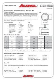
Bauen Sie Jetzt das Piccoboard ein<br />
Dazu benötigen Sie folgende Komponenten:<br />
4 Adernendhülsen ( enthalten im Liefer umfang), Schere<br />
Schrumpfschlauch ( enthalten im Lieferumfang) Messer oder<br />
Wärmequelle ( z.b. Heißluft-Gebläse), Flachzange<br />
Dem nun folgenden Bauabschnitt sollten Sie genau befolgen<br />
damit die Funktion des Piccoboard gewährleistet ist.<br />
Zur Vorbereitung am Standart Piccoboard befinden sich 4<br />
Leitungen(Kabel) Abb. 1 die einseitig abisoliert sind mit den<br />
Farben 2 x Rot, 1 x Blau, 1 x Schwarz. Die genaue Belegung<br />
entnehmen Sie bitte der unten Angeführten Tabelle.<br />
Abb.1<br />
Als erstes Verbinden wir die Zuleitung zum Hauptmotor. Dazu<br />
nehmen Sie bitte das rote Kabel mit dem Querschnitt 0,25<br />
mm² vom Hauptmotor sowie das rote Kabel mit dem<br />
Querschnitt 0,25mm² vom Piccoboard und fassen die beiden<br />
Kabel mit der einen Hand zusammen und verdrillen die Kabel-<br />
Adern ( Kupferdrähte ) zwischen Ihren Zeigefinger und<br />
Daumen. siehe Abb. 2<br />
Abb.3<br />
Farbe Funktion Querschnitt<br />
Rot Hauptmotor + Pol 0,25 mm²<br />
Schwarz Hauptmotor- Pol 0,25 mm²<br />
Rot Heckmotor + Pol 0,14mm²<br />
Blau Heckmotor- Pol 0,14 mm²<br />
Abb.2<br />
Diesen Vorgang wiederholen Sie bitte mit den Schwarzen<br />
Kabeln die ebenfalls den gleichen Querschnitt von 0,25 mm²<br />
haben.<br />
Als nächsten Arbeitsschritt werden nun die mitgelieferten<br />
Adernendhülsen bis auf die Kunstoff-Isolation aufgeschoben.<br />
Siehe Abb.3<br />
Abb.4<br />
Nachdem Sie die Adernendhülsen aufgeschoben haben,<br />
müssen Sie unter zu Hilfenahme der Flachzange die Aderendhülsen<br />
zusammen quetschen. Es ist darauf zu Achten das<br />
die Adernendhülsen einen absoluten festen Sitz vorweisen.<br />
Da es sonst zu Verbindungsstörungen kommen kann (<br />
Wackelkontakt) . Siehe Abb. 4<br />
Nun haben wir die Kabel des Hauptmotors mit dem<br />
Piccoboard verbunden und müssen diese noch mit dem<br />
mitgelieferten Schrumpfschlauch isolieren.<br />
Bitte beachten Sie Farben der Kabel sowie die des<br />
Schrumpfschlauches, d.h. rot zu rot und schwarz zu schwarz.<br />
Den Schrumpfschlauch werden wir nun mit Hilfe des Messers<br />
ablängen. Sie sollten darauf achten das der Schrumpfschlauch<br />
länger ist als die Adernendhülsen d.h. in unserem<br />
Fall ca. 10 mm lang.<br />
Schieben Sie nun den Schrumpfschlauch über die<br />
Abb.5<br />
Abb.6<br />
11<br />
Adernendhülsen, so dass der Schrumpfschlauch ca. 4<br />
mm über die Isolation des Kabels ragt. Siehe Abb. 5<br />
Nachdem Sie nun den Schrumpfschlauch<br />
aufgeschoben haben werden wir mit Hilfe der<br />
Wärmequelle ( z.B. Heißluftfön) den Schrumpfschlauch zum<br />
Schrumpfen bringen. Siehe Abb.6.. Dabei sollten Sie jedoch<br />
darauf achten das die Temperatur nicht zu hoch ist da<br />
ansonsten das Kabel beschädigt wird.<br />
Diesen Vorgang sollten Sie nun wiederholen um den<br />
Heckmotor am Piccoboard anzuschließen. Auch hier ist es<br />
sehr wichtig das sie die Farben der Kabel ( Querschnitt 0,14<br />
mm ) richtig zuteilen d.h. rot zu rot und blau zu blau.<br />
Achtung: Verbinden Sie das Board noch nicht mit dem<br />
Accupack! Bitte folgen Sie zunächst den weiteren<br />
Anweisungen zum Aufbau, insbesondere muß immer zuerst<br />
der Sender, dann der Empfänger eingeschaltet werden!<br />
Stecken Sie alle Anschlüsse außer dem Flugakku ein, legen<br />
Sie dann das Board auf den Vorbau, und zwar so, daß die<br />
Anschlüsse nach hinten und die LED in Flugrichtung nach<br />
links weisen. Alle Kabel müssen so verlegt werden, daß sie<br />
keinesfalls an bewegte Teile des Hubschraubers kommen<br />
können. Nun wird das Piccoboard mit dem 2-Seiten-<br />
Klebeband befestigt.<br />
Als nächstes verlegen Sie dann die Empfangs-antenne,<br />
indem Sie sie zu einer Kufe führen und dort mit Klebeband so<br />
fixieren, daß noch ca 10 cm der Antenne frei hängen können.<br />
Jetzt wird noch der Flugakku mit einem Gummiring unter dem<br />
Vorbau befestigt. Den Ring hängen Sie dazu seitlich an der<br />
Querstange ein.<br />
Durch Verschieben des Akkus nach vorne oder hinten wird<br />
der Schwerpunkt eingestellt. Dazu halten Sie den<br />
Hubschrauber an der Hillerstange, stellen diese quer zum<br />
Rumpf und beobachten die Kufen. Diese sollen genau parallel<br />
zu Ihrer Bau-unterlage (Tisch) verlaufen. Verschieben Sie den<br />
Akku, bis dies erreicht ist.
Die Fernsteuerung Das Fliegen<br />
12<br />
Dazu halten Sie den Hubschrauber an der<br />
Hillerstange, stellen diese quer zum Rumpf und<br />
beobachten die Kufen. Diese sollen genau parallel zu<br />
Ihrer Bauunterlage (Tisch) verlaufen. Verschieben Sie<br />
den Akku, bis dies erreicht ist.<br />
Nun wird die Kabinenhaube montiert. Schieben Sie die<br />
Haube von vorne auf das Modell und drücken Sie die<br />
=<br />
beiden an der Haube festgeklebten Gummitüllen auf die<br />
Querstange. Achten Sie bitte darauf, daß der Kleber an der<br />
Haube getrock<strong>net</strong> ist, sie klebt sonst fest und Sie bekommen<br />
sie sonst nur schwer oder gar nicht mehr herunter.<br />
Als letztes fehlen nun noch die Rotorblätter. Diese werden mit<br />
Kunststoffschrauben M2,5x8 von unten an den Rotorkopf<br />
geschraubt (Schraube von oben, Rotorblatt, U-Scheibe und<br />
Mutter von unten). Die Wellenlinie auf dem Rotorblatt ist oben.<br />
Die Schrauben für die Rotorblätter dürfen nicht zu fest<br />
angezogen werden, nur soweit, daß die Rotorblätter<br />
durch ihr Eigengewicht gerade nicht mehr aus ihrer<br />
Position schwenken. Sind die Schrauben hier zu fest<br />
angezogen, kann der Hubschrauber in Vibrationen kommen,<br />
sind sie zu locker, ist das Hochfahren der Rotordrehzahl<br />
erschwert.<br />
Nun schalten Sie zuerst den Sender ein, stellen alle<br />
Trimmschieber auf Mitte und ziehen den Gasknüppel und die<br />
Gastrimmung in die tiefste Position. Erst danach wird der<br />
Flugakku ins Piccoboard eingesteckt. Fangen die Servos<br />
unkontrolliert an zu zittern, so liegt ein Problem mit der Sende-<br />
und Empfangsanlage vor. Ziehen Sie sofort den Flugakku<br />
wieder ab, und prüfen Sie den Aufbau; wahrscheinlich sind<br />
die Quarze nicht oder falsch eingesteckt.<br />
Bleiben die Servos ruhig, so lassen Sie den Hubschrauber<br />
solange ruhig stehen, bis die rote LED am Piccoboard<br />
aufleuchtet, das dauert ca. 5-7 sec. Die Elektronik ist jetzt<br />
aktiv.<br />
Bleiben Sie mit dem Gas in tiefster Position und führen Sie<br />
einen Rudercheck durch. Wenn Sie am Nickknüppel ziehen,<br />
muß sich die Taumelscheibe nach hinten neigen, bewegen<br />
Sie den Rollknüppel nach links, so neigt sich auch die<br />
Taumelscheibe nach links. Geben Sie nun langsam etwas<br />
Gas. Der Hauptrotor setzt sich in Bewegung und etwas später<br />
folgt der Heckrotor.<br />
Nehmen Sie das Gas wieder zurück und ziehen Sie den<br />
Stecker des Flugakkus heraus. Schalten Sie erst danach die<br />
Fernsteuerung aus.<br />
Herzlichen Glückwunsch, Sie haben es geschafft. Vor<br />
Ihnen steht jetzt Ihr <strong>FUN</strong> <strong>Piccolo</strong> und wartet auf seinen<br />
Erstflug. Bevor es aber soweit ist, laden Sie bitte erst alle<br />
Akkus.<br />
Dann können wir uns dem Kapitel Fliegen zuwenden.<br />
Jetzt wird es langsam ernst. Der Fun <strong>Piccolo</strong> ist fertig<br />
aufgebaut, die Akkus (auch vom Sender!) sind geladen und<br />
nun soll der Hubschrauber zeigen, was in ihm steckt. Dazu<br />
benötigen wir zunächst ein Fluggelände. Ideal ist zum Beginn<br />
eine kleine Halle oder ein größerer Raum, möglichst ohne<br />
Hindernisse. Über die Höhe brauchen Sie sich vorläufig noch<br />
keine Gedanken zu machen. Im Raum sollte auf jeden Fall<br />
Windstille herrschen. Zugluft, z. B. durch ein geöff<strong>net</strong>es<br />
Fenster oder Ähnliches sollte vermieden werden. Ein ebener,<br />
glatter Boden, auf dem der Hubschrauber rutschen kann, ist<br />
zu empfehlen, tiefe weiche Teppiche eher nicht.<br />
Stellen Sie den <strong>Piccolo</strong> in die Mitte der freien Fläche. Schalten<br />
Sie den Sender ein, schieben alle Trimmschieber in die<br />
Mittelposition und stellen das Gas auf niedrigste Position. Nun<br />
wird der Flugakku eingesteckt. Nach der obligatorischen<br />
Pause (3-5 sec., bis die LED leuchtet) prüfen Sie bitte<br />
nocheinmal die richtige Funktion der beiden Servos. Wenn<br />
alles funktioniert, stellen Sie sich etwa 2 m hinter den<br />
Hubschrauber, leicht seitlich versetzt, um auch die Nase<br />
beobachten zu können. Dann geben Sie langsam Gas, bis<br />
der Hubschrauber anfängt, „leicht“ zu werden, d. h. irgendeine<br />
Bewegung zu zeigen. (Gasgeben ist hier im übrigen ein<br />
etwas übertragener Begriff, eigentlich geben wir Volt).<br />
Beobachten Sie dabei zunächst vorne die Nase. Dreht Sie<br />
nach rechts, so schieben Sie den Trimmschieber für den<br />
Heckrotor ein wenig nach links (und umgekehrt).<br />
Nun der nächste Versuch, wieder bis eine Reaktion erfolgt.<br />
Besteht die Reaktion darin, daß der Hubschrauber ohne<br />
wegzudrehen abhebt, so ist alles in Ordnung - aber halt!,<br />
soweit sind wir noch nicht, also wieder Gas wegnehmen und<br />
vorerst auf dem Boden bleiben. Es kann auch der Fall<br />
auftreten, daß der Hubschrauber zunächst nach links<br />
wegdrehen will, dann bei mehr Gas gerade bleibt und bei noch<br />
mehr Gas nach rechts dreht (auch hier ist immer die Nase<br />
gemeint), was sich mit der Trimmung nicht ausgleichen läßt.<br />
Dann stimmt die Heckbeimischung im Piccoboard nicht ganz.<br />
Diese regelt die Drehzahl des Heckrotors in Abhängigkeit von<br />
der Drehzahl des Hauptrotors, um das Drehmoment auszugleichen.<br />
Im eben beschriebenen Fall ist die Heckbeimischung<br />
von Hauptrotor zu Heckrotor zu stark. Um dies<br />
zu ändern, drehen Sie am Poti (Wie in der Piccoboardanleitung<br />
beschrieben ist). Danach müssen Sie evtl. den<br />
Trimmschieber neu justieren und sich so an die optimale<br />
Abstimmung herantasten. Seien Sie dabei bitte geduldig, die<br />
korrekte Einstellung erleichtert Ihnen später alle weiteren<br />
Schritte. Beim Poti für die Kreiselempfindlichkeit sollten Sie<br />
die werkseitige Voreinstellung zunächst beibehalten.<br />
Wenn es soweit ist, daß sich die Nase des Hubschraubers<br />
nicht mehr dreht, wenn Sie das Gas hochfahren, beobachten<br />
sie als nächstes die Nickfunktion (Vor-/Rückwärts). Der<br />
Hubschrauber wird durch Gasgeben wieder ganz „leicht“<br />
gemacht. Will er nach vorne wegrutschen, so schieben Sie<br />
den Trimmschieber der Nickfunktion etwas nach hinten (und<br />
umgekehrt), solange bis keine Nickbewegung mehr feststellbar<br />
ist, wenn Sie das Gas vorsichtig bis kurz vor dem<br />
Abheben hochschieben.<br />
Sie sollten übrigens wirklich bis an die Abhebegrenze gehen,<br />
wenn die Taumelscheibe gerade steht und Sie korrekt gebaut<br />
haben, kann dabei nichts passieren. Wichtig ist nur, daß Sie<br />
ganz langsam Gas geben und auch langsam wieder Gas<br />
herausnehmen<br />
Etwas komplizierter verhält es sich mit der Rollfunktion<br />
(seitwärts). Durch den seitlichen Schub des Heckrotors wird<br />
der Hubschrauber später im Flug ein wenig nach rechts
Das Fliegen<br />
Rechts (Roll rechts)<br />
drücken)<br />
(Nick<br />
Vorwärts<br />
r<br />
o<br />
t<br />
H<br />
E<br />
c<br />
K<br />
o<br />
r<br />
r<br />
e<br />
c<br />
h<br />
t<br />
s<br />
Steigen (mehr Drehzahl)<br />
H e c k r o t o r l i n k s<br />
„hängen“, dies ist nicht vermeidbar. Damit die Rollfunktion wie<br />
analog für Nick beschrieben am Boden ausgetrimmt werden<br />
kann, sind die vertikalen Streben der linken Kufe etwas länger<br />
als die der rechten.<br />
Als nächstes müssen wir uns nun kurz vom Boden trennen.<br />
Also das schon bekannte Vorgehen, Gas geben, „leicht“<br />
werden lassen und den Gasküppel vorsichtig weiterschieben,<br />
bis der <strong>Piccolo</strong> abhebt. Die Reaktionen beobachten, evtl.<br />
gegensteuern und bitte beim ersten Anzeichen von Unsicherheit<br />
wieder landen. Jetzt kommt nämlich das eigentliche<br />
Fliegenlernen. Dies kann Ihnen niemand abnehmen und das<br />
einzige was hilft, ist Üben, Üben, Üben...<br />
Aber so schlimm ist es nun auch wieder nicht, Tausende<br />
Modellheli-Piloten haben es auf genau diese Art und Weise<br />
gelernt, viele in einer Flugschule, die die ersten Schritte<br />
natürlich sehr beschleunigt und das Absturzrisiko minimiert,<br />
aber viele auch ganz allein.<br />
Eine echte Hilfe für Anfänger und Fortgeschrittene stellt ein<br />
sogenannter Flugsimulator wie der Aerofly Proffessional<br />
bzw.EasyFly von IKARUS dar, hier kann man die Feinmotorik<br />
der Steuerung lernen, ohne Sorge um sein Modell haben zu<br />
Sinken (weniger Drehzahl)<br />
Links (Roll links)<br />
Rückwärts (Nick ziehen)<br />
13<br />
müssen. Ein moderner Flugsimulator kann die Flugeigenschaften<br />
Ihres Modells verblüffend echt simulieren und hilft<br />
Ihnen nicht nur bei den Anfängen, sondern z. B. auch beim<br />
später beschriebenen ,Nasenschweben“ und beim Erlernen<br />
vieler Flugfiguren.<br />
Wie auch immer, das weitere Vorgehen besteht zunächst<br />
stets aus diesen kurzen „Hüpfern“, schauen Sie das Modell<br />
genau an und versuchen Sie, seine Reaktionen mit Ihrem<br />
Sender auszusteuern. Stellen Sie den <strong>Piccolo</strong> vor jedem Start<br />
wieder in die Mitte Ihrer Flugfläche (oder etwas rechts davon),<br />
um genügend Platz zu haben. Auch spätere Champions<br />
haben genau so begonnen, verlieren Sie also bitte nicht die<br />
Geduld.<br />
Sie werden merken, daß Ihre Flüge mit der Zeit immer länger<br />
werden, ohne daß Sie sich zum Boden „retten“ müssen.<br />
Bleiben Sie einstweilen trotzdem in einer maximalen Flughöhe<br />
von 20-30 cm, nur dann können Sie den Boden als<br />
Trainingshilfe nutzen, er ist zunächst Ihre beste Sicherheit.<br />
Achten Sie auch bei diesen ersten kurzen Schwebeflügen auf<br />
Ihre Heckrotortrimmung und die Beimischung sowie auf Ihre<br />
Trimmschieber. Will der Hubschrauber in der Luft immer in
Das Fliegen<br />
14<br />
dieselbe Richtung wegschweben, so trimmen Sie nach,<br />
bis keine eindeutige Tendenz mehr zu erkennen ist. Es<br />
liegt leider im Wesen des Hubschraubers, daß er all<br />
seine Freiheitsgrade immer nutzt, also nicht von Natur<br />
aus in der Luft einfach stillsteht, steuern müssen Sie also<br />
immer etwas.<br />
Versuchen Sie, mit möglichst kleinen Korrekturen auszukommen.<br />
Je eher Sie eine Bewegung des Modells bemerken<br />
und darauf reagieren, desto kleiner ist das erforderliche<br />
Gegensteuern und die Abweichung in der Schwebeposition.<br />
Achten Sie auch immer darauf, daß der Hubschrauber mit<br />
dem Heck zu Ihnen zeigt; wenn er sich dreht, wird vieles<br />
komplizierter: Zeigt z. B. die Nase zu Ihnen, ist für Sie (nicht<br />
für den Hubschrauber) plötzlich links und rechts vertauscht<br />
(wie vor einem Spiegel). Später werden Sie lernen, auch mit<br />
dieser Situation umzugehen. Vorläufig stehen Sie immer<br />
hinter dem Hubschrauber.<br />
Sie sind nun sicherer, können den Hubschrauber in der Luft<br />
(weitgehend) stabil schweben lassen und fragen sich, was Sie<br />
als nächstes tun sollen. Wenn Sie etwas Platz haben, können<br />
Sie mit dem <strong>Piccolo</strong> „spazieren“ gehen, d. h. einen langsamen<br />
Vorwärtsflug einleiten und die Geschwindigkeit dann konstant<br />
halten. Oder Sie versuchen es mal mit dem<br />
Seitwärtsschweben, Sie bleiben stehen und der Hubschrauber<br />
fliegt vor Ihnen seitlich hin und her (das Heck zeigt<br />
immer noch zu Ihnen, jedenfalls 45°). Steigern Sie dabei auch<br />
langsam die Flughöhe. Sie werden merken, daß der <strong>Piccolo</strong> in<br />
größerer Höhe ruhiger fliegt. Dies liegt daran, daß er aus<br />
seinen eigenen Abwindwirbeln, die am Boden umgelenkt<br />
werden, herauskommt und in ruhigerer Luft schwebt. Diesen<br />
Effekt werden Sie übrigens auch beim Fliegen in kleinen<br />
Räumen bemerken, nach einer gewissen Zeit ist die Raumluft<br />
ziemlich turbulent und der Hubschrauber wird unruhig.<br />
Landen Sie dann und warten eine Minute, schon geht´s<br />
wieder besser.<br />
Jetzt haben Sie schon eine ganze Menge Akkufüllungen<br />
„verflogen“. Sie können den <strong>Piccolo</strong> ruhig und stationär<br />
schweben lassen, ihn bewegen und wieder anhalten, die<br />
Flughöhe variieren und sind nun bereit, Ihre ganze Halle als<br />
Fluggelände zu nutzen. Wie Sie sicher schon bemerkt haben,<br />
ist der Start inzwischen einfacher als die Landung, das liegt an<br />
den oben beschriebenen Luftverwirbelungen. Aber so<br />
schwierig ist eine Punktlandung nun auch wieder nicht,<br />
probieren Sie es einfach mal. Der <strong>Piccolo</strong> nimmt Ihnen auch<br />
eine Bruchlandung nicht immer übel, er ist ziemlich robust,<br />
wenngleich natürlich auch nicht unzerstörbar.<br />
Als nächstes gehen Sie mal mit dem Hubschrauber ins Freie,<br />
vielleicht haben Sie einen Garten und ein windarmer Abend<br />
ist die rechte Gelegenheit, dem <strong>Piccolo</strong> mal etwas Auslauf zu<br />
geben. Fangen Sie langsam an und achten Sie darauf, daß<br />
die Nase nicht auf Sie zuzeigt, das wollen wir nämlich jetzt erst<br />
lernen.<br />
Gehen Sie das sog. Nasenschweben zuerst im Geist durch<br />
oder üben es am Simulator: die Rollfunktion scheint verkehrt,<br />
beim Nick drücken fliegt der Hubschrauber plötzlich auf Sie zu<br />
statt von Ihnen weg und auch der Heckrotor ist gewöhnungsbedürftig.<br />
Allein Steigen und Sinken bleiben wie zuvor.<br />
Schweben Sie also ruhig vor sich, drehen dann den<br />
Hubschrauber langsam mit dem Heckrotor um und<br />
versuchen Sie, die Fluglage zu stabilisieren. Versuchen Sie<br />
nicht, gleich beim ersten Versuch 180° zu schaffen, drehen<br />
Sie den <strong>Piccolo</strong> lieber wieder in die gewohnte Lage zurück,<br />
sobald Sie merken, daß Sie unsicher werden. Auch hier macht<br />
nur Übung den Meister.<br />
Bald werden Sie das Nasenschweben beherrschen; achten<br />
Sie darauf, daß Sie den Hubschrauber nicht nur von einer<br />
Seite zu sich drehen, sondern von beiden. Damit können Sie<br />
im Prinzip schon die nächste Figur, die sog. Pirouette, das ist<br />
eine langsame Drehung des schwebenden Hubschraubers<br />
um die Hochachse.<br />
Wie Sie sicher schon gemerkt haben, hat sich die Situation<br />
inzwischen geändert, nicht mehr der Boden, sondern der freie<br />
Luftraum ist jetzt Ihre Zuflucht im Fall der Unsicherheit geworden.<br />
Das ist auch völlig in Ordnung, der <strong>Piccolo</strong> ist ja<br />
schließlich ein Fluggerät. Nutzen Sie also weiterhin alle<br />
Möglichkeiten zum Üben, auch und gerade im Freien, denn<br />
nur die Manöver, die Sie wirklich beherrschen, sollten Sie<br />
auch im Indoor-Bereich fliegen. Dann gibt es kaum noch<br />
Grenzen für Sie, Sie können starten und landen, wo Sie<br />
wollen, mit etwas Übung durch offene Türen fliegen und Ihre<br />
Gäste verblüffen.<br />
Wir werden nicht aufhören, den <strong>FUN</strong> <strong>Piccolo</strong> noch weiter für<br />
Sie zu verbessern. Fordern Sie einfach unsere neueste Info<br />
oder unseren neuesten Katalog an.<br />
Wir wünschen Ihnen viele schöne Flüge und viel Spaß mit<br />
Ihrem <strong>FUN</strong> <strong>Piccolo</strong>.<br />
Garantie:<br />
Dieses Qualitätsprodukt wurde vor dem Versand sorgfältig geprüft.<br />
Sollte es dennoch einmal einen Grund zur Beanstandung geben, so<br />
bearbeiten wir Garantieansprüche gemäß unseren aktuellen<br />
Allgemeinen Geschäftsbedingungen. Bei Einsendung eines Gerätes,<br />
das sich nach der Eingangsprüfung als funktionsfähig herausstellt,<br />
erheben wir eine Bearbeitungsgebühr von €21.-. Nach unserer<br />
Erfahrung funktioniert das Produkt mit allen gängigen R/C Systemen.<br />
Wir können jedoch keine Gewähr für die Funktion mit einem bestimmten<br />
R/C-System übernehmen, da die Beschaffenheit des Steuerimpulses<br />
eines Empfängers keiner Normung unterliegt. Ebenso müssen wir die<br />
Verantwortung für Folgeschäden aus der Verwendung unseres<br />
Produktes ablehnen, da uns die Überwachung der sachgerechten<br />
Verwendung unmöglich ist. Abschneiden der Original-Kabel führt zum<br />
Garantieverlust.<br />
Sicherheitshinweise:<br />
Das CE-Zeichen ist kein Freibrief für den sorglosen Umgang mit den<br />
Geräten. Meiden Sie den Gefahrenbereich von Motoren, Propellern,<br />
Getrieben und Rotoren. Betrachten Sie elektrische Systeme stets als<br />
potentiell gefährlich. Entfernen Sie immer den Akku, wenn Sie daran<br />
arbeiten. Vermeiden Sie unmittelbare Feuchtigkeit und Feuchtigkeit<br />
durch Kondensation. Das Produkt ist nicht verpolungsgeschützt!<br />
Verpolung oder Vertauschen der Kabel können zu irreparablen Schäden<br />
führen. Steckverbindungen müssen stets zueinander passen.<br />
Improvisationen können zu Schäden führen. Beachten Sie den<br />
Empfangsteil der Stromversorgung, insbesondere den Kreisel. Mehr als<br />
die vorgesehene Last können die Spannungsversorgung und<br />
angeschlossene Geräte beschädigen. Trennen Sie nie einen<br />
elektrischen Verbraucher vom Akku, wenn dieser noch in Betrieb ist.<br />
Betriebshinweise:<br />
Schalten Sie immer zuerst den Sender ein, dann den Empfänger. Achten<br />
Sie darauf, daß der Gasknüppel auf Stop steht. Beachten Sie auf jeden<br />
Fall, daß Sie Ihre Frequenz exklusiv verwenden und niemand sonst Ihre<br />
Frequenz verwendet. Achten Sie auf das CE-Zeichen der anderen<br />
Komponenten. Entstören Sie Motoren mit mindestens 2 keramischen<br />
Kondensatoren mit 10-100 nF/63-100V und ggf. weiteren<br />
Entstörmaßnahmen (Filter, Drossel). Führen Sie die Antenne mehr als 3<br />
cm entfernt von Motor, Akku, Regler und deren Kabel. Montieren Sie den<br />
Empfänger möglichst weit entfernt vom Motor, Regler und Akku. Halten<br />
Sie die Kabel so kurz wie möglich. Motor- und Akkukabel sollten verdrillt<br />
sein. Wenn Sie Ihr Modell nicht benutzen, entfernen Sie die Akkus und<br />
lagern Sie das Modell trocken bei normaler Luftfeuchtigkeit. Sollte das<br />
System ungewohnt funktionieren, trennen Sie den Flugakku vom<br />
System und verbinden Sie ihn erst wieder nach einer Wartezeit von 5-10<br />
s.
Übersicht<br />
15<br />
67360<br />
67361<br />
67362<br />
67363<br />
67364<br />
67365<br />
67366<br />
67368<br />
67369<br />
67370<br />
67371<br />
67372<br />
67392<br />
67365<br />
67378<br />
67411<br />
67361<br />
67373<br />
67375<br />
67376<br />
67377<br />
67411<br />
69020<br />
67380<br />
69021<br />
67378<br />
69022<br />
67383<br />
67384<br />
67385<br />
67386<br />
67387<br />
67385<br />
67388<br />
67375<br />
67391<br />
67561<br />
67393<br />
67395<br />
67397<br />
67402<br />
67396<br />
67399<br />
69029<br />
67401<br />
67400<br />
67367<br />
67367<br />
69028<br />
69028<br />
67582<br />
67371<br />
69025<br />
67397<br />
67394<br />
67631
Übersicht<br />
16<br />
Stückliste <strong>FUN</strong>-<strong>Piccolo</strong><br />
Artikel, die mit einem * gekennzeich<strong>net</strong> sind, können<br />
nur in Verpackungseinheiten bestellt werden.<br />
Stk. Best.Nr. Teile Maße (mm)<br />
1 68245 Chassis 110 x 95 x 20<br />
2 67361 Kufe * 120 x 10 x 5<br />
1 67362 Heckgehäus e 28 x 24 x 20<br />
1 67363 Heckz ahnrad Ø 25 x 10,5<br />
1 67364 Taumelscheibe 44,5 x 38,2 x 7,5<br />
2 67365 Kugelcli p *<br />
1 67366 Ts-Mitnehmer 25,5 x 8,5 x 2,5<br />
2 67367 Steuerst angen f. Hiller * 24,3 x 5 x 2,9<br />
2 67368 Paddelst euerhebel * 24,3 x 5 x 2,10<br />
1 67369 Zentralstück 24,3 x 5 x 2,11<br />
1 67370 Rotorkopf 24,3 x 5 x 2,12<br />
2 67371 Hillerpaddel * 24,3 x 5 x 2,13<br />
1 67372 Hauptantriebsrad 96Z 24,3 x 5 x 2,14<br />
1 67373 Ritzel 10Z / 9Z / 8Z Bohrung 2mm /<br />
2 67375 Hauptrotorblätt er * 243 x 42 x 8<br />
1 67376 Heckrotorblat t 146 x 35 x 10<br />
1 67377 Paddelst ange CFK Ø 2 x 175<br />
2 67411 lange CFK St angen * Ø 2 x 87<br />
2 67378 kurze CFK Stangen * Ø 2 x 80<br />
1 69020 Heckrotorwelle (S tahl) Ø 2 x 40<br />
1 67380 Kabinenhalterung CFK Ø 2 x 60<br />
1 69021 Heckrohr CFK Ø 5 x 320<br />
1 69022 Hauptrotorwelle St ahl Ø 3 x 98<br />
1 69025 Hecks porn (Stahl) Ø 1 x 80<br />
1 67383 Kabinenhaube *<br />
1 67384 Kabinenverglasung<br />
1 67385 Kabinenhalterung * 2 x 5 x 3<br />
1 67386 Seitenleit werk ABS 0.2mm 60 x 40<br />
1 69030 Dekorbogen<br />
1 67387 Steuergest änge lang (Stahl) *<br />
1 67392 Steuergest änge kurz (St ahl) *<br />
2 69029 Kunsts tofflager * 3 x 7 x 3<br />
4 69028 Kunsts tofflager * 2 x 6 x 3<br />
2 67391 Schrauben * M 1,4 x 4<br />
5 67561 Schrauben * M 2 x 6<br />
2 67393 Schrauben Kuns tstoff * M 2,5 x 8<br />
2 67395 Muttern K unsts toff * M 2,5<br />
4 67582 Muttern * M 2<br />
2 67394 Schrauben M 2. 6 * M 2,6 x 5<br />
2 67397 Unterlegsc heiben * M 2,5<br />
1 67631 Unterlegsc heiben * M 3<br />
2 67396 Unterlegsc heiben * M 1,4<br />
1 67399 Zylinderstift * M6 1 x 8<br />
1 67400 Zylinderstift M 6 1x12mm * M6 1 x 12<br />
4 67388 Silik onschlauc h * 5 x 3<br />
1 69024 Kabelverbindung Heckmot or 0,15 x 380<br />
1 69023 Kabelverbindung Hauptmotor 0,25 x 40<br />
1 67401 Hauptantriebsm otor G-295<br />
1 67402 Heckantri ebsmotor<br />
1 69031 Bauanleitung<br />
2 69032 Adernendhülsen 0,34²<br />
2 69033 Adernendhülsen 0,75²
17<br />
Fehlerbehebung<br />
Fehlerbehebung<br />
Folge<br />
mögliche Ursache<br />
Problem<br />
Der Emfängerquarz, welcher normalerweise<br />
dem Sender beiliegt, muß wie abgebildet am<br />
Picccoboard eingesteckt werden.<br />
Der Empfänger kann die Signale<br />
vom Sender nicht empfangen.<br />
Der Empfängerquarz am Piccoboard<br />
ist nicht eingesteckt.<br />
Piccoboard Piccoboard arbeitet nicht<br />
richtig, oder oder gar nicht.<br />
Überprüfen Sie, ob beide Quarze denselben<br />
Kanal haben. Achtung: Quarze nicht vertauschen<br />
(Sender= TF bzw. Tx / Empfänger=RA<br />
bzw. Rx).<br />
Der Empfänger kann die Signale<br />
vom Sender nicht empfangen.<br />
Empfänger- und Senderquarz<br />
passen passen nicht zusammen (Unterschiedliche<br />
Kanäle), oder sind<br />
beschädigt.<br />
beschädigt.<br />
Servos und und Motoren<br />
arbeiten nicht.<br />
Stecken Sie die Stecker von Board und Servos<br />
wie beschrieben am Empfänger ein.<br />
Achten Sie auf richtige Polung derselbigen.<br />
Ist dies der Fall, wird der Empfänger<br />
nicht mit Strom versorgt und kann<br />
nicht funktionieren.Die Elektronik<br />
wird bei verdreht eingesteckten<br />
Steckern in der Regel nicht<br />
beschädigt.<br />
Die Die beiden Servostecker (braun/<br />
Rot/orange) Rot/orange) vom Piccoboard<br />
sind sind verdreht, oder gar nicht am<br />
Empfangsteil Empfangsteil des Piccoboards<br />
eingesteckt.<br />
eingesteckt.<br />
Korrigieren Sie die Heckbeimischung wie<br />
beschrieben.<br />
Das Heck dreht sich weg.<br />
Heckbeimischung Heckbeimischung stimmt nicht.<br />
<strong>Piccolo</strong> dreht sich nach<br />
dem Abheben.<br />
Achten Sie auf die richtige Einbaulage des<br />
Piccoboards.<br />
Der Kreisel korrigiert die falsche<br />
Achse.<br />
Das Piccoboard wurde falsch<br />
aufgeklebt.<br />
Der Kreisel arbeitet nicht<br />
richtig. richtig.<br />
Überprüfen Sie den Heckantrieb, insbesondere<br />
auf Leichtgängigkeit.<br />
Der Heckrotor hat nicht genug<br />
Leistung. Leistung.<br />
Der Heckrotorantrieb ist nicht in<br />
Ordnung.<br />
Stecken Sie den Flugakku ab und stellen Sie die<br />
Potis wie abgebildet auf die Grundeinstellung<br />
zurück. Es ist ratsam, nach jeder Verstellung den<br />
Akku kurz abzuklemmen, um Abweichungen<br />
beim Einlesen zu vermeiden.<br />
Bei allzugrober allzugrober Verstellung wird es<br />
schwierig, schwierig, den richtigen Einstellpunktpunkt<br />
wiederzufinden.<br />
Die 2 Trimmpotis reagieren sehr<br />
feinfühlig und dürfen desshalb<br />
nur vorsichtig verstellt<br />
werden.<br />
Heckbeimischung lässt<br />
sich nicht einstellen. einstellen.<br />
Drehen Sie die Empfindlichkeit zurück ( - ).<br />
Der Kreisel Kreisel übersteuert<br />
Die Kreiselempfindlichkeit ist zu<br />
weit aufgedreht<br />
Heck pendelt beim<br />
Schweben.
Aufrüstkit zum ECO <strong>Piccolo</strong><br />
Mit diesem Kit können sie Ihren <strong>Piccolo</strong> Fun zu einem<br />
ECO <strong>Piccolo</strong> aufrüsten.<br />
Im Kit enthalten sind alle erforderlichen Teile wie<br />
Kugellager, CFK-Wellen, Tuningmotor usw.<br />
Best.- Nr. 69100<br />
PRO <strong>Piccolo</strong> Neu<br />
<strong>Piccolo</strong> Pro – 3-D-Fliegen in Perfektion !<br />
Durch konsequente Weiterentwicklung wurde ein Produkt geschaffen, das<br />
in seiner Art einzigartig ist. Technisch raffiniert und jedes Detail ausgearbeitet,<br />
ist ein Hubschrauber entstanden, der seinesgleichen sucht.<br />
Dieses kleine Kraftpaket wurde auf Kunstflug und 3-D-Flug getrimmt.<br />
Der starke Powermotor 410 Pro verleiht diesem formschönen<br />
Hubschrauber Steigleistungen, die bis dato nicht denkbar waren. Die<br />
speziell für diese Konstruktion entwickelten symetrischen Rotorblätter<br />
verhalten sich neutral und lassen Kunstflug in all seinen Spielarten zu. Ob<br />
Sie Rollen, Loopings oder Rückenflug fliegen wollen, mit dem <strong>Piccolo</strong> Pro<br />
ist dies auf kleinstem Raum möglich.<br />
Durch den bereits eingebauten Freilauf können Sie Autorotationslandungen<br />
ausführen. Das Modell kann perfekt schweben und folgt Ihren<br />
Steuerbefehlen absolut exakt. Durch ein genial einfaches System ist es<br />
möglich, diesen Hubschrauber schon mit einer einfachen 4-Kanal-Fernsteuerung<br />
zu fliegen. Sie brauchen deshalb keinen aufwendigen Sender,<br />
um diesen Hubschrauber der Extraklasse im Kunstflug zu bewegen. Um<br />
das volle Potential, einschließlich Rückenflug, zu nutzen, ist ein<br />
Computersender zu empfehlen.<br />
Um die absolute Performance in Leistung und Wirkungsgrad zu erreichen<br />
empfehlen wir den Einsatz unseres Brushless-Motors. Mit diesem<br />
Antriebskonzept wird aus Ihrem <strong>Piccolo</strong> Pro ein Spitzenhubschrauber, der<br />
extrem lange Flugzeiten mit Power satt verspricht.<br />
Best.-Nr. 68200<br />
ECO-<strong>Piccolo</strong> Nachtflug-Set<br />
<strong>Piccolo</strong>-Fliegen bei völliger Dunkelheit!<br />
Bausatz bestehend aus einfach aufzubauenden Elektronik-Elementen.<br />
Beleuchtung schaltet sich mit anlaufendem Rotor automatisch ein.<br />
Best.-Nr. 67415<br />
Langflug-Set für Eco <strong>Piccolo</strong>,<strong>Piccolo</strong> Fun und <strong>Piccolo</strong> Pro<br />
Mit diesem Set eröffnen sich völlig neue Möglichkeiten für Sie. Flugzeiten<br />
von über 30 Minuten sind problemlos erreichbar. Durch die hohe<br />
Spannungslage werden sehr gute Leistungen erzielt. Lithium-Ionen-Akkus<br />
sind in der Lage, bei geringem Gewicht hohe Kapazitäten abzugeben. Die<br />
1000 mA-Zelle wiegt 90 g. Die Zellen sind mit einer speziellen<br />
Schutzbeschaltung versehen, um ein Tiefentladen der Zelle zu verhindern.<br />
Das speziell für Li-Ionen-Akkus entwickelte Automatik Ladegerät ist nach<br />
neuestem Stand der Technik gefertigt und besitzt eine Abschaltung für<br />
schonende Ladung Ihrer Akkus. Der Tuning-Motor 310 L ist speziell auf den<br />
Einsatz von Lithium-Zellen abgestimmt.<br />
Um den Motor bei langen Flugzeiten kühl zu halten, liegt dem Set noch ein<br />
Lüfter bei. Benutzen Sie das Ladegerät ausschließlich für Li-Ionen-Akkus.<br />
Set mit 1000 mA-Akku Best.-Nr. 67484<br />
Set mit 2000 mA-Akku Best.-Nr.67 485<br />
18
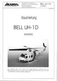
Der Original Bell UH-1D war ein Mehrzweckhubschrauber, der auch als<br />
„Teppichklopfer“ bekannt ist. Er wurde in sehr hoher Stückzahl produziert<br />
und war mit einem 1100 PS starkem Lycoming-Triebwerk ausgestattet.<br />
Der Modellrumpfbausatz für den <strong>Piccolo</strong> ist im Maßstab 1:22 naturgetreu<br />
nachgebaut. Durch das geringe Gewicht des Rumpfes (ca. 30 g) ist die<br />
Flugzeit, je nach Akku, nur eine halbe bis eine Minute kürzer als beim <strong>Piccolo</strong><br />
mit der Trainer-Kabinenhaube. Die Flugstabilität und Flugruhe wird durch den<br />
Rumpf sogar positiv beeinflußt.<br />
Inhalt: Rumpf, sep. Fahrwerk, Leitwerksteile, Innenteile, zwei verschiedene<br />
Dekobögen,Tuning Motor G 310<br />
Technische Daten<br />
Gewicht: ca. 30 g<br />
Maße B x L: 115 x 540 mm Best.-Nr.68350<br />
19<br />
Bell UH-1D<br />
Bell 222/Airwolf<br />
Die Bell 222 ist im Original ein sehr eleganter Zivilhubschrauber der<br />
Extraklasse und kann eine zwei Mann-Besatzung und fünf Passagiere<br />
aufnehmen. Er hat zwei Lycoming-Triebwerke mit je 675 PS. Die<br />
Reisegeschwindigkeit ist 265 km/h. Die Dienstgipfelhöhe beträgt ca.<br />
6000 Meter und die Reichweite ca. 520 km. Das maximale Startgewicht<br />
ist 3650 kg. Die Rumpflänge beträgt 10,98 m. Der Modellbausatz ist<br />
extrem leicht und hat wie das Original ein einziehbares Fahrwerk. Wie<br />
das Filmvorbild kann auch hier der Rumpf als Airwolf lackiert werden. Als<br />
normale Bell 222 sind verschiedene Lackierungen möglich. Bei<br />
Verwendung des Einziehfahrwerks setzen Sie unser Piccoboard plus mit<br />
fünf Kanälen ein. Außerdem wird ein weiteres Servo Best.-Nr. 171100<br />
benötigt.<br />
Technische Daten<br />
Gewicht: ca. 30 g<br />
Maße B x L: Breite: Stummelfläche: 170 mm<br />
Länge: 600 mm<br />
Rumpfbausatz Hughes 300<br />
Im Original ist die zweisitzige Hughes 300 eine der meist verkauften<br />
Helicopter. Sie wurde für militärische Einsätze, für Schulungsflüge, für<br />
landwirtschaftliche Nutzung und auch sehr häufig für private Zwecke<br />
eingesetzt.<br />
Das Mehrgewicht des Rumpfbausatzes beträgt nur<br />
ca. 5 g, so daß die Flugzeit unmerklich geringer ist.<br />
Airwolf Best.-Nr. 68351<br />
Bell 222 Best.-Nr. 68353<br />
Bausatzinhalt: Kabinenhaube, weiße Haupt- und Heckrotorblätter,<br />
weiße Kufen, Leitwerke, Tankattrappen, Dekobogen.<br />
Maße B x L: 80 x 460 mm (Gesamtlänge)<br />
Material: ABS Best.-Nr. 68352<br />
Neu Fliegen wie die Großen<br />
Bausatzinhalt: Rumpf, Leitwerk, Räder, Einziehfahrwerk,<br />
Tuning-Motor G-310.<br />
Träume werden wahr!<br />
3D Pitch-Umrüst-Kid für den <strong>Piccolo</strong>.<br />
Mit viel Aufwand wurde ein völlig neuartiger Rotorkopf entwickelt.<br />
Mit diesem Set wird aus Ihrem Einsteiger-Indoor-Helikopter ein kraftvoller Kunstflug-<br />
Hubschrauber, bei dem nur der Pilot die Grenzen setzt. Er zeigt bei gleichbleibender<br />
Flugzeit nicht nur ungeahnte Flugeigenschaften, Fliegen bei jedem Wetter wird zum<br />
Erlebnis. Der Bausatz beinhaltet unter anderem 9 Kugellager, CNC-gefräßte<br />
Holzrotorblätter mit Bespannfolie, einen neuen, verstärkten<br />
Taumelscheibenmitnehmer, sowie eine neue Taumelscheibe. Bei entsprechender<br />
Senderprogrammierung mit Gasvor-wahl, wird der <strong>Piccolo</strong> voll kunstflugtauglich.<br />
Der neuartige Rotorkopf er-möglicht aber auch, durch ein V-Kabel mit einem<br />
einfachen Vierkanal-sender zu fliegen.<br />
Wir werden nicht aufhören, den <strong>FUN</strong> <strong>Piccolo</strong> noch weiter für Sie zu verbessern. Fordern Sie einfach unsere neueste<br />
Info oder unseren neuesten Katalog an.<br />
Wir wünschen Ihnen viele schöne Flüge und viel Spaß mit Ihrem <strong>FUN</strong> <strong>Piccolo</strong>.
Bei Rückfragen und technischen<br />
Problemen nutzen Sie unsere Service-<br />
Hotline-Nr. 0190-795020<br />
(Erreichbar von Montag bis Freitag in<br />
der Zeit von 8.00 bis 17.00 Uhr € 1,24<br />
Min)<br />
Bei Beanstandungen und<br />
Ersatzteilbestellungen wenden Sie sich<br />
bitte an:<br />
Tel.-Nr. 07402-929190<br />
Fax-Nr.07402-929150<br />
E-mail: ikarus @ t-online.de<br />
_____________________________________<br />
Flugmodelle sind kein Kinderspielzeug. Für den Bau und<br />
insbesondere den anschließenden Betrieb sind Sachkenntnisse<br />
erforderlich. Fehler und Unachtsamkeiten beim<br />
Zusammenbau und dem anschließenden Betrieb können<br />
schwerwiegende Personen- und Sachschäden zur Folge<br />
haben. Da Hersteller und Verkäufer keinen Einfluß auf den<br />
ordnungsgemäßen Zusammenbau und Betrieb des Modelles<br />
haben, wird auf diese Gefahren ausdrücklich hingewiesen<br />
und jegliche Haftung für Personen- , Sach- und sonstige<br />
Schäden ausgeschlossen.<br />
Aufbau und Betrieb des Modelles nur von Erwachsenen oder<br />
unter Aufsicht und Überwachung durch Erwachsene.<br />
Achtung!!!<br />
Befolgen Sie genauestens die Montage- und Betriebsanleitung.<br />
Änderungen des Aufbaus und Nichteinhalten der<br />
Betriebsanleitung führen zum Verlust jeglicher Gewährleistungsansprüche.<br />
Wenden Sie sich für den Aufbau und den Modellbetrieb an<br />
erfahrene Modellflieger, am besten an Vereine oder<br />
Flugschulen. Es empfiehlt sich, eine Haftpflichtversicherung<br />
für den Modellbetrieb abzuschließen. Auskünfte hierzu<br />
erteilen z.B. auch die Vereine.<br />
Auch vom vorschriftsmäßig aufgebauten Modell können<br />
Gefahren ausgehen. Greifen Sie niemals in sich drehende<br />
Luftschrauben/Rotorblätter und sonstige, offenliegende, sich<br />
bewegende Teile, da ansonsten schwerwiegende Verletzungen<br />
entstehen können.<br />
Passanten und Zuschauer müssen einen ausreichenden<br />
Schutzabstand zum betriebenen Modell einhalten. Halten Sie<br />
Abstand zu Hochspannungsleitungen. Betreiben Sie das<br />
Modell nicht auf öffentlichen Straßen, Plätzen, Schulhöfen,<br />
Parks, Spielplätzen usw. Halten Sie den für das<br />
entsprechende Modell vorgeschriebenen Mindestabstand zu<br />
bewohnten Gebieten ein.<br />
Grundsätzlich hat sich jeder Modellflieger so zu verhalten,<br />
daß die öffentliche Sicherheit und Ordnung, Personen und<br />
Sachen sowie die Ordnung des Modellflugbetriebes nicht<br />
gefährdet oder gestört werden.<br />
Verwenden Sie nur Akkus mit vorgeschriebener Zellenzahl<br />
<strong>Ikarus</strong> France<br />
19, Rue Desaix<br />
Strasbourg-Nord<br />
67450 Mundolsheim<br />
Tèl.: 03 88 18 11 11<br />
Fax: 03 88 18 11 17<br />
E-mail: info @ ikarus-france.com<br />
<strong>Ikarus</strong>-USA<br />
5876 Enterprise Parkway<br />
Billy Creek Commerce Center<br />
Fort Myers, FL 33905, USA<br />
Phone: 239-690-0003<br />
Fax: 239-690-0028<br />
E-mail:Info@ikarus-usa.com<br />
Sicherheitshinweise für den Betrieb von Elektroflugmodellen.<br />
Diese Hinweise sowie die Montage- und Betriebsanleitung müssen vor der Inbetrieb-nahme<br />
des Modelles sorgfältig und voll-ständig durchgelesen werden!<br />
und Kapazität. Bei zu hoher Zellenzahl kann der Elektromotor<br />
überlastet werden, durchbrennen, in Brand geraten und<br />
Funkstörungen verursachen. Die Luftschraube/Rotorbläter<br />
bzw. die Schraubenaufhängung können reißen und die<br />
Bruchstücke mit hoher Geschwindigkeit in alle Richtungen<br />
wegfliegen. Bei zu geringer Zellenzahl ist ein störungsfreier<br />
Betrieb ebenfalls nicht möglich.<br />
Verwenden Sie immer voll geladene Akkus. Landen Sie das<br />
Modell rechtzeitig, bevor entladene Akkus zu Fehlfunktion<br />
oder unkontrolliertem Absturz führen können.<br />
Prüfen Sie vor jedem Flug die RC-Anlage auf korrekte<br />
Funktion. Ruderausschläge müssen z.B. in die richtige<br />
Richtung gehen. Vergewissern Sie sich vor dem Einschalten<br />
des Modelles, da der eingestellte Kanal wirklich nur von Ihnen<br />
genutzt wird.<br />
Achten Sie auf freie Start- und Lan<strong>def</strong>lächen. Be-<br />
obachten Sie das Modell im Flug ständig.<br />
Führen Sie beim Fliegen keine abrupten Steuerknüppelbewegungen<br />
durch.<br />
Fliegen Sie nie auf Personen bzw. Tiere zu und überfliegen<br />
Sie diese auch niemals.<br />
Verwenden Sie nur die vorgesehenen, verpolungsicheren<br />
Stecksysteme. Bei Verpolung besteht Kurzschlußgefahr.<br />
Kurzgeschlossene Akkus können explodieren.<br />
Nehmen Sie an den Motoren die dafür vorgesehenen<br />
Entstörmaßnahmen vor (Enstörkondensatoren und ggfls.<br />
zusätzliche Drosseln).<br />
Von den für den Zusammenbau notwendigen Werkzeugen<br />
geht Verletzungsgefahr aus. Ebenfalls besteht Verletzungsgefahr<br />
bei abgebrochenen oder nicht entgrateten Modellteilen.<br />
Klebstoffe und Lacke können gesundheitsgefährdende<br />
Substanzen wie Lösungsmittel usw. enthalten. Beachten Sie<br />
die Herstellerhinweise und tragen Sie ggfls. eine Schutzbrille.<br />
Gummiteile wie z.B. Gummiringe können altern, spröde und<br />
unbrauchbar werden, müssen vor Gebrauch also getestet<br />
werden.
<strong>FUN</strong> <strong>Piccolo</strong> Building Instructions<br />
Welcome to Indoor R/C Helicopter<br />
flying<br />
Thank you...<br />
for purchasing the revolutionary <strong>FUN</strong> <strong>Piccolo</strong>. The <strong>Piccolo</strong> is a<br />
new state-of-the-art electric R/C model helicopter that at last<br />
makes indoor flying' a practical reality. Latest technology<br />
design and production processes plus extensive R&D ensure<br />
incredible flight performance/flying time even when using a<br />
standard 4 channel R/C transmitter. As a bonus, the extensive<br />
use of carbon fibre materials has imparted a quite amazing<br />
strength/weight ratio to this model, helping to make it a<br />
practical outdoor, calm weather flying machine.<br />
The contents of this kit have been carefully packed and<br />
checked at the factory. However, please inspect the kit<br />
carefully to ensure that all parts are present and undamaged.<br />
Please inform us immediately if you find anything missing or<br />
damaged.<br />
Care and safety...<br />
Always take great care when constructing any R/C model; the<br />
<strong>Piccolo</strong> is no exception. From the box to the flying field, the<br />
<strong>Piccolo</strong> will provide you with a great deal of fun and<br />
satisfaction. However, please be aware that this helicopter is<br />
NOT A TOY. It must be assembled with care and responsibility.<br />
It should be operated only in a safe manner and in safe areas.<br />
Your <strong>Piccolo</strong> should never be flown irresponsibly or without<br />
due regard for other people or property.<br />
Flying R/C model helicopters is not difficult but requires<br />
patience and practice. If you are a newcomer to R/C model<br />
helicopters, you should seek advice from your local model<br />
club or store/shop before flying your <strong>Piccolo</strong>. <strong>Ikarus</strong> and<br />
<strong>Ikarus</strong>' distributors will not be held liable for any loss or<br />
damage arising from misuse or improper operation of this<br />
model.<br />
Helicopters are subject to certain physical laws and an<br />
understanding of the principles of flight is important. A clear<br />
understanding of the principles of flight can make the allimportant<br />
difference between executing a 'good' landing as<br />
opposed to a 'bad' landing. Small and sensitive control inputs<br />
are needed when flying helicopters. Care and patience is the<br />
key to success. The <strong>Piccolo</strong> is the result of extensive design<br />
evolution and testing and this is reflected in the high quality<br />
components and excellent performance of this model. This, by<br />
itself, does not guarantee success. The quality and 'flyability'<br />
of the constructed model is down to you. To ensure success,<br />
please follow the instructions in this manual carefully and<br />
study R/C model helicopter flight technique diligently.<br />
Construct the helicopter as carefully as<br />
possible. When in doubt, 'draw out' the problem on paper.<br />
Consider and reconsider the problem before proceeding.<br />
Don't hesitate to seek help from a more experienced<br />
helicopter modeler.<br />
Product guarantee...<br />
We guarantee this product to be free of <strong>def</strong>ects in materials or<br />
workmanship for a period of SIX MONTHS from date of<br />
purchase. The user assumes all responsibility for the proper<br />
use and operation of this product, and no warranty is<br />
expressed or implied regarding the care and operation of this<br />
product.<br />
Items not included in the kit...<br />
<strong>Ikarus</strong> Piccoboard<br />
(FM receiver, Dual speed controllers and Piezo gyro and<br />
21<br />
electronic mixing, all in one package)<br />
Frequency: Part:<br />
35MHz 720635 <strong>Ikarus</strong> Piccoboard<br />
40/41MHz 720640 <strong>Ikarus</strong> Piccoboard<br />
72MHz 720672 <strong>Ikarus</strong> Piccoboard<br />
N.B. Check with your dealer for the frequencies available for<br />
your particular country. R/C frequency laws vary from country<br />
to country.<br />
Servos: 171201 Pico-Servo(x2)<br />
Battery: 67492 8-cell battery pack<br />
R/C Transmitter: 173506 35Mhz 4-6 channel<br />
174006 40/41Mhz<br />
720672 72Mhz<br />
Charger: 67489 4-10 cells<br />
Dimensions:<br />
Main Rotor Diameter: 520 mm<br />
Fuselage Length: 500 mm<br />
Weight: 280 g<br />
Required tools:<br />
Required for construction:<br />
--Razor or hobby knife<br />
--Fine and Medium-fine grain sandpaper<br />
--Cups for small parts<br />
--Needle-nose pliers<br />
--Tape<br />
--Metric ruler or Vernier<br />
Symbols:<br />
In order to bring your attention to specific steps in the<br />
sequence, we have used symbols. They have the following<br />
meanings...<br />
Special care is necessary here<br />
Use cyanoacrylate glue here<br />
WARNING!:<br />
Cyanoacrylate (CA) glue bonds skin instantly. In case of eye<br />
contact, avoid blinking, rinse with water and seek medical<br />
attention immediately. Keep CA glue out of the reach of<br />
children. Avoid breathing vapors. Use only in well ventilated<br />
areas.<br />
General:<br />
This helicopter is unique because of it's miniature<br />
components. The components are weight-optimized and<br />
small. Therefore, they require special care when being<br />
handled. Examine parts for any molding flash and other<br />
molding imperfections before each step. Remove burrs or<br />
flash with a sharp knife or sandpaper.<br />
During assembly, use CA glue sparingly. Using too much glue<br />
does not build a stronger machine, just a heavier one. Also,<br />
over-use of glue will complicate disassembly in the future. Be<br />
careful when applying CA to parts because CA can run and<br />
possibly wick into parts you do not want to glue. Use CA<br />
conservatively!<br />
Make sure that all surfaces to be joined with CA glue are clean<br />
and free of dirt, grease or oil. Also, clean all parts before gluing<br />
to free them of any left-over mold release agent. Different CA<br />
glues have different cure times. Full strength is achieved after<br />
12 hours. CA glue requires humidity (moisture) to cure, so it<br />
sometimes helps speed the set time to breathe on the glue.<br />
Depending on the moisture conditions, CA can harden in
Welcome to Indoor R/C<br />
Helicopter flying<br />
22<br />
seconds. In case of skin contact, wash with warm, soapy<br />
water. Acetone or nail-polish remover can be used to<br />
soften CA glue for removal from skin. Actually, CA glue<br />
will come off of skin by itself with time due to the oils skin<br />
produces. Excess dry CA can be rubbed off skin with a pumice<br />
stone.<br />
Excess dry CA can be rubbed off skin with a pumice stone.<br />
CA glues can be hazardous to health when used incorrectly.<br />
Because of the pungent odor, CA glues must only be used in<br />
well-ventilated areas. CA glue has a limited shelf-life. Keep CA<br />
glue in a cool, dry place with the cap firmly secured after<br />
opening.<br />
Use caution when tightening bolts or screws. Motor retaining<br />
bolts, for example, only require minimum tightness.<br />
Remember when tightening, for example, flybar paddle<br />
screws, that they are threaded into plastic. It is easy to strip the<br />
plastic if too much force is used. If any components' thread or<br />
material is damaged by excessive tightening; it must be<br />
replaced. Spare parts are obtainable from your dealer.<br />
IKARUS WISHES YOU LOTS OF <strong>FUN</strong> AND<br />
ENJOYMENT IN THE BUILDING AND FLYING<br />
OF YOUR <strong>FUN</strong> PICCOLO<br />
Glossary<br />
For newcomers to model helicopter flying, we will explain<br />
some of the special terms and a little theory.<br />
MECHANICS:<br />
The sum of all components in the helicopter chassis (including<br />
the main rotor, drive gears, frame, shafts and rods).<br />
SWASHPLATE:<br />
This is the connection device for the cyclic control. It consists<br />
of the outer ring, a bearing, and an inner plate. The outer ring is<br />
connected to servos and does not revolve itself. Servo<br />
movements are directed by means of the swashplate through<br />
to the rotor head, or main rotor.<br />
MAIN ROTOR:<br />
This is responsible for steering the helicopter in flight. It<br />
consists of rotor head, rotor blades, flybar and flybar paddles.<br />
Cyclic control commands are sent via the swashplate through<br />
to the rotor head.<br />
ROTOR BLADES:<br />
These are the rotating 'wings' of the aircraft. They generate lift<br />
and allow the machine to fly.<br />
FLYBAR PADDLES:<br />
These serve a dual function; they both stabilize and steer the<br />
main rotor blades. The paddles are operated by the<br />
swashplate and associated linkages.<br />
TAIL ROTOR:<br />
This rotor generates the thrust required to counter the torque<br />
generated by the main rotor. The tail rotor controls the<br />
helicopter about the yaw axis.<br />
SERVOS:<br />
These are highly geared motor and electronic units that<br />
control the swashplate.<br />
SPEED CONTROLLER:<br />
This is the electronic device that controls the power delivered<br />
to the main electric drive motors.<br />
RECEIVER:<br />
Receives control commands from your transmitter and sends<br />
appropriate signals to servos and speed controllers.<br />
GYRO:<br />
This is an electronic stabilization device. It senses motion. In<br />
helicopters, it usually stabilizes the helicopter tail, dampening<br />
unwanted yaw inputs, thus greatly simplifying flying.<br />
MIXER:<br />
This co-ordinates the speed of the main and tail rotors. It alters<br />
tail rotor thrust so that increases or decreases in power do not<br />
cause unwanted yawing. Receiver, mixers, piezo gyro and<br />
speed controllers are all combined into the Piccoboard.<br />
Basics<br />
How does a <strong>Piccolo</strong> helicopter fly?<br />
A helicopter generates its lift from rotating wings (the rotor<br />
blades). As engine speed is increased, the main rotor revolves<br />
faster and therefore generates more lift. Conversely, as motor
Basics<br />
speed is reduced; lift is also reduced. However, a motor driven<br />
rotor system generates torque that acts on the helicopter<br />
fuselage, twisting the fuselage in the opposite direction to the<br />
main rotor. This torque is countered by thrust generated by a<br />
smaller rotor on the tail (tail rotor). The blades that comprise<br />
the tail rotor have a certain pitch angle that, when rotating at a<br />
given speed, generate thrust and balance exactly the main<br />
rotor torque. By increasing or decreasing the speed of the tail<br />
rotor-and hence varying the thrust generated, the helicopter<br />
yaws either left or right.<br />
At this point, we have covered two of the functions required to<br />
control a helicopter. The first: height control, via an increase or<br />
decrease in main rotor speed. The second: yaw control, by<br />
speeding up or slowing down the tail rotor. A model helicopter<br />
must also be controlled about two further axes: roll and pitch.<br />
This task is undertaken by the cyclic control system. The<br />
system consists of servos, swashplate, flybar paddles and<br />
main rotor blades.<br />
The servos are connected to the lower swashplate ring. The<br />
upper swashplate ring is connected to the flybar paddles.<br />
When a servo moves, it tilts the swashplate and the control<br />
input is fed by pushrods 'cyclically' up into the main rotor<br />
system. Note that the swashplate is connected (via linkages)<br />
to the flybar and the angle of the paddles is altered as a result.<br />
At this stage, think of a helicopter as a flying disc. The paddles<br />
and blades together actually resemble a disc in flight. The<br />
cyclic controls are responsible for steering the helicopter by<br />
tilting the disc in flight. The disc can be tilted forwards/<br />
backwards or left/right. For example, by pushing the cyclic<br />
stick forward in flight, the disc is tilted forwards and the nose of<br />
the helicopter drops. The cyclic control system can move the<br />
disc forwards, backwards, left or right and hence direct the<br />
helicopter in a very precise way. Two servos are responsible<br />
for cyclic control: one servo for roll control (left and right) and<br />
one for forwards and backwards control (fore and aft).<br />
N.B. The Piccoboard (see below) features an electronic piezo<br />
gyro for stabilization of the yaw axis. This keeps the machine<br />
stable in yaw and hence eases pilot workload considerably.<br />
Included towards the rear of the manual is an exploded view of<br />
the <strong>Piccolo</strong>. Use this as a guide prior to construction and<br />
during construction. The associated parts list provides useful<br />
descriptions and dimensions (where appropriate) of parts<br />
used.<br />
If you are in any doubt about which parts should be used<br />
during construction, refer to the exploded view and take note<br />
of the descriptions and dimensions of the required parts.<br />
Measure the parts if you are in any doubt.<br />
Be very sparing with both glue and adhesive tape. Every gram<br />
of additional weight will reduce flight time by around four to five<br />
seconds.<br />
The one-piece Piccoboard (not included in kit) electronic<br />
control system has been designed to save a considerable<br />
amount of weight when compared with conventional, heavier<br />
electronic control systems consisting of separate receiver,<br />
controllers, gyro, etc.<br />
The Piccoboard combines all these functions in one compact,<br />
lightweight unit and also removes the need for a tail rotor<br />
servo.<br />
Assembly<br />
Landing gear assembly<br />
23<br />
First, lightly roughen with sandpaper all areas to be<br />
bonded. Identify the landing gear struts, they are in the<br />
bag with the other small carbon fibre components. The struts<br />
are 4 identical length carbon fibre rods. Use the exploded list<br />
at the back of this manual as an aid to parts identification. Glue<br />
the rear undercarriage struts 1 to the chassis using CA as<br />
illustrated in the diagram. When the glue has cured, clip the<br />
front struts 2 into the chassis and adjust their position so that<br />
the assembly sits level on a table. When satisfied, add a drop<br />
of glue. Finally, add the landing skids 3 and glue them to the<br />
struts. Glue also the carbon fibre canopy mount to the chassis.<br />
Make sure this sits centered on the chassis.<br />
3.<br />
67380<br />
2.<br />
86 mm<br />
67411<br />
rear view<br />
67360<br />
1.<br />
67378<br />
67361<br />
3.<br />
67411<br />
80 mm<br />
67378<br />
Pls. note that the struts have different lenghts. When taking off<br />
the different lengths compensate the slight vertical turning of<br />
the main rotor axis which occurs due to the side thrust of the<br />
tail rotor and the clockwise rotation of the main blades. Thus<br />
taking off is easier.
Landing gear assembly<br />
24<br />
Push the main rotor shaft into the main gear. Rotate the<br />
gear so that the hole in the main shaft lines up with the<br />
hole in the gear. Identify the steel main gear retaining pin<br />
(length 8mm, the shortest of the metal rods) and press<br />
the pin through the hole in the gear and through the main<br />
shaft. Press the two main plastic bushings into the housings in<br />
the main frame, then slide the main shaft through the bearings<br />
and retain the shaft by sliding the washer and one of the<br />
rubber mount grommet down over the top of the main shaft<br />
and pushing it securely into position against the upper main<br />
plastic bushings. The main shaft and gear assembly should<br />
freely rotate in the plastic bushings with no float up or down.<br />
67385<br />
69029S<br />
67631<br />
67399<br />
Two types (main drive motor, tail drive motor) of small plastic<br />
pinion gear are included in the kit. Press the nine-tooth<br />
standard pinion onto the drive motor so that the end of the<br />
pinion and the motor shaft are flush. N.B. Option pinion gears<br />
(8 and 10 tooth) are supplied in the kit.<br />
67401<br />
69029<br />
69022<br />
67373<br />
67372<br />
Fit the motor using two M 2,6x5 mm bolts and washers. Adjust<br />
the motor position so that the gears do not engage tightly, but<br />
have a little play or backlash. The proper mesh between the<br />
motor pinion and the main gear is achieved by placing a small<br />
strip of paper (standard 80gsm photocopier paper) between<br />
the gears. Next, move the motor up against the main gear.<br />
Tighten the motor retaining bolts. Then remove the paper.<br />
Check that there is a small amount of backlash present and<br />
that as you rotate the main gear; no tight spots exist.<br />
67397<br />
67394<br />
Take time to get the correct gear mesh because the<br />
smoothness of running, flight duration and service life of<br />
the motor depend on this! N.B Do not over-tighten the<br />
motor screws. They should be just tight enough not to<br />
come loose. The screws should be checked after flying to<br />
ensure that they have not loosened.<br />
Before you start to build in the main rotor motor you should<br />
break-in the motor. This also increases the durability and<br />
effeciency. As long as the motor is not broken-in, it could<br />
eventually produce radio interferences due to heavy<br />
collector lightning. On other receivers than the <strong>Ikarus</strong> one<br />
this could result in slight pulses on the servos.<br />
Breaking-in the motor<br />
Switch on your tx. Set the throttle stick to power-off<br />
position. Plug the main rotor motor and a full charged<br />
battery into the Piccoboard. After waiting for the LED to<br />
activate, set the throttle stick to about 1/4 of full power<br />
position. Now let the motor spin until the battery is<br />
discharged. Repeat the whole procedure 2 or 3 times.
The rotorhead<br />
Ball links are the most important connection elements in a<br />
helicopter. They should be free of any play, but smooth in<br />
movement with no binding.<br />
N.B. Due to manufacturing limitations, this cannot be perfectly<br />
preset at the factory. Therefore, the links are a little too tight<br />
and require adjustment by the builder.<br />
The swashplate comes pre-assembled. Press a ball-link onto<br />
it's corresponding ball on the swashplate. At this point, check<br />
for any binding in the link. Swing the link in all directions. If you<br />
notice that the link cannot be moved without binding, carefully<br />
squeeze the ball-link on the ball with needle-nose pliers. Start<br />
with just a little pressure, and recheck the link. Proceed this<br />
way until the link can slide freely on the ball. Do this to all of the<br />
ball links.<br />
WARNING: Squeeze carefully to avoid damaging the ball<br />
joints!<br />
flat<br />
rounded<br />
You can see in the illustration below which linkage goes to<br />
which ball. Notice that the flat side of the ball-link goes toward<br />
the inside of the ball and the rounded surface faces outboard.<br />
Note also that the upper swashplate arms are of 2 different<br />
lengths: short and long. Ensure that the ball links are correctly<br />
fitted to the appropriate arms.<br />
long arm<br />
short arm<br />
25<br />
Slide the swashplate onto the main rotor shaft and press<br />
the center hub (part no. 67369) onto the shaft. Line up<br />
the center hub hole with the hole in the main shaft. The<br />
steel anti-rotation link pin must be pushed through the<br />
center hub and the corresponding hole in the main shaft. Then<br />
press the two 2x6 mm plastic bushings onto the molded posts<br />
at the top of the center hub.<br />
67364<br />
69028<br />
67369<br />
Snap the rotor head plate (pt no 67370) into place on the two<br />
center hub ball bearings. You will notice some free play as you<br />
rock the plate. This is intentional and is a feature of the rotor<br />
head design.Place the small hooked part of the anti-rotation<br />
link over one side of the anti rotation pin, then carefully bend<br />
the other side under and onto the opposite pin. Bend the anti<br />
rotation link down and snap the ball link onto one of the short<br />
arms attached to the inner ring of the swashplate. Note that the<br />
flat side of the ball link lies to the inside of the ball.<br />
67370<br />
69028<br />
69022<br />
67400<br />
67366<br />
flat<br />
rounded
The rotorhead<br />
Slide the carbon flybar(67377) through the rotor head. Check that it can rotate freely without binding. Rotate the flybar<br />
26 repeatedly if it shows any sign of binding or sticking. Alternatively, carefully sand the center section of the<br />
flybar evenly with superfine sandpaper. The flybar must rotate smoothly with no binding. Repeat<br />
the above procedure if binding still exists.<br />
Slide the flybar control arms (67368) onto the flybar and retain them with the 2x6 mm<br />
bolts and nuts so that the flybar is centered and the flybar control arms are<br />
parallel to each other. Make sure that the flybar can still be rotated easily, and<br />
that it has just a tiny bit of end float.<br />
67368<br />
67377<br />
flybar<br />
Slide the flybar paddles(67371) onto the flybar until they are<br />
flush with the outer sides of the fastening strap. Retain the<br />
paddles with 2x6 mm screws. The paddles must lie parallel<br />
both to each other and also to the flybar control arms. Carefully<br />
align these items because it is very important for correct flight<br />
performance. At the same time as aligning the paddles, you must ensure that the flybar assembly is perfectly balanced.<br />
In order to check the flybar is centered precisely, measure the distance from paddle tip to rotor head center. The distance should<br />
be identical for both paddles. Adjust the position of the flybar if necessary.<br />
To balance the flybar assembly, temporarily disconnect the ball joints from the flybar control arms. The completed flybar<br />
assembly is now free to rock on its two ball bearing pivots. Place the machine on a flat surface and observe the flybar and<br />
paddles. If the same paddle<br />
67561<br />
67582<br />
67582<br />
67371<br />
flybar<br />
paddle<br />
Snap the two flybar control links into their sockets in the flybar control arms and onto the longer<br />
ball arms of the upper swashplate ring. Once again, note that the flat side of the link goes to<br />
the inside of the swashplate ball.<br />
flat<br />
67561<br />
always drops, measure again to<br />
ensure that they are equidistant<br />
from the rotor head center. If they<br />
are not, correct this. If absolutely<br />
necessary, add a piece of tape to<br />
the lighter paddle to achieve<br />
proper balance of the flybar<br />
assembly.The assembly is<br />
correctly balanced when the<br />
flybar paddles sit horizontally<br />
without any tendency to drop to<br />
one side.Check now that all<br />
linkages are correctly attached<br />
and that nothing is too stiff to<br />
move freely.<br />
67367<br />
rounded
The rotorhead<br />
Push the 2x6 mm plastic bushings into the tail rotor housing. Slide the tail shaft No.69020 through the plastic bushings and<br />
mount the tail rotor drive gear and tail rotor blade assembly as shown.<br />
N.B. Press the tail rotor blade assembly into position between the positioning lugs molded into<br />
the drive gear.<br />
67376<br />
Retain the tail output shaft assembly with silicone tube retainers, one<br />
retainer slipped over each end of the shaft.<br />
WARNING! The tail blades have very sharp edges as a<br />
result of the molding process. Carefully sand any sharp<br />
edges to blunt them and render them safe.<br />
67388<br />
Check that the complete tail shaft assembly does<br />
not float from side to side. Adjust the silicone<br />
67376<br />
retainers until this is achieved.<br />
The tail rotor assembly should now freely rotate on the bearings. Hold the housing so that the tail rotor is horizontal<br />
and observe whether or not one blade or the other always rotates to the bottom. If one blade is out of balance you<br />
must stick a small piece of Tesa film (supplied) to the lighter blade to achieve a prefect balance. Imbalance of the tail rotor will<br />
cause severe vibration.<br />
67391<br />
67396<br />
67404<br />
Fit the tail motor into the slots in the tail housing using two 1.5x3 mm bolts and<br />
washers. Adjust the backlash between the tail gear and motor pinion by slipping a<br />
piece of paper between the two. Push the motor up against the tail gear and tighten<br />
the motor bolts.<br />
N.B. Not too tightly or you may strip the threads. Remove the paper strip. Check that there is a small amount of backlash between<br />
the gears and no binding of the gears is detectable during rotation. N.B. Proper backlash adjustment is essential for achieving<br />
good flight times and long motor life. Now glue the tailskid into place.<br />
67363<br />
69028<br />
67362<br />
69028<br />
69020<br />
27
Assembly<br />
28<br />
Roughen the ends of the tail boom where it will be glued. Pass the tail motor leads through the<br />
tail housing, then through the tail boom. Slide the tail housing onto the tail boom and glue it in<br />
place using CA. Route the tail motor leads through the main chassis and push the boom into<br />
place. Position the tail boom, so that the tail rotor output shaft is positioned exactly<br />
perpendicular to the main rotor shaft. Once positioned correctly, glue the boom in place by<br />
adding a drop of CA through the slot in the chassis.<br />
Attach the thin plastic tail fin to the boom and<br />
tailskid with two pieces of tape.<br />
67384<br />
67383<br />
Klebefilm/<br />
tape<br />
Carefully cut out the body and the screen<br />
using the molded lines as a guide. (Note<br />
that the right canopy has a lip to which the<br />
left side will be glued). The two body halves are joined first.<br />
The tinted screen is glued into position from the inside. Since<br />
these parts are very light and flexible, it is best to tape them together first, then apply a small amount of CA to the joints. When the<br />
glue has cured, holes must be made in the body to accept the rubber body mount grommets (67385). The body has two small<br />
indentations molded in the place where the holes must be made. The holes should be approximately 3mm diameter. Push the<br />
mount grommets(67385) into place. The body is now ready for decal application.Apply the decals using the scheme illustrated<br />
on the box as a guide.<br />
69030<br />
67385<br />
tape<br />
67386
Remote control<br />
Remove the mounting lugs from the servos using a sharp<br />
knife or a pair of scissors.<br />
67387 1. 67365<br />
2.<br />
Assemble the steel cyclic pushrods by first placing a rod into<br />
the hole in the ball-link, then rotating it 90 degrees until it snaps<br />
shut.<br />
2.<br />
1.<br />
cut off<br />
Connect the servos to the appropriate pins of the Piccoboard.<br />
Remove the arms or discs from the servos. Set the transmitter<br />
trims to their neutral positions. Turn on the transmitter and plug<br />
the battery into the Piccoboard. The servos will center. Using a<br />
medium length servo arm, push the arms onto the servos and<br />
secure with screws.<br />
Unplug the servos and battery for now. Attach the pushrods to<br />
the servos at the outer servo-arm hole and swing upward.<br />
The fore and aft (forwards and backwards) servo uses the<br />
longer pushrod. Press the ball link into the corresponding rear<br />
ball of the swashplate. Now position the servo where it is to be<br />
glued to the surface of the frame, so that the swashplate is<br />
level and the linkage lines up straight.<br />
Once you are completely satisfied that the servo is accurately<br />
positioned, pull the servo back just enough to drip some CA<br />
between the surfaces of the servo and the mount area. Press<br />
the servo back into position and hold in place for a few<br />
seconds.<br />
Push-rods<br />
67387<br />
Nickservo<br />
The roll servo must next be fitted. The pushrod is<br />
attached to the servo arm and the ball link attached.<br />
Place the ball link onto the corresponding ball on the<br />
outside ring of the swashplate. Center and level the<br />
swashplate as per the fore and aft servo. Once done, attach<br />
this servo using the same technique.<br />
It is possible that despite of careful positioning of the roll<br />
and elevator servos; the swashplate may not sit perfectly<br />
level-even when your transmitter trims are in their neutral<br />
position with the servo output arms perfectly horizontal.<br />
Servo push-rods, part numbers 67387 and 67411 feature a<br />
V-shaped bend that allows the pushrod to be effectively<br />
lengthened or shortened in order to achieve a perfectly<br />
level swashplate.<br />
Use a pair of pliers as illustrated to adjust the pushrod<br />
length by a small amount in order to achieve a level<br />
swashplate with transmitter trims centered and servo<br />
control horns horizontal.<br />
Rollservo<br />
Push-rods<br />
67392<br />
The swashplate should now be level and perpendicular with<br />
the main rotorshaft. The servo arms should be perfectly<br />
horizontal with R/C switched on, transmitter sticks centered<br />
and trims centered.<br />
29
Install the Piccoboard Now.<br />
30<br />
You will need these components:<br />
4 crimp sleeves (not included in set)<br />
A apir of flat nose pliers<br />
shrink tubing (not included in set)<br />
knife and pair of scissor<br />
heat source (i.e. heat gun)<br />
In order to guarantee the correct function of the Piccoboard,<br />
please follow thes instructions in this section carefully.<br />
The standard Piccoboard features four cables (in the colors 2<br />
x red, 1 x blue, 1 x black), which already have been stripped<br />
off their insulation on either end (picture 1).<br />
The functional reference is:<br />
picture 1<br />
Color Function cable dia.<br />
Red Main motor + pole 0.,25mm²<br />
Black Main motor- pole 0.25 mm²<br />
Red Tail motor + pole 0.14 mm²<br />
Blue Tail motor - pole 0.14 mm²<br />
First we connect the cables to the main motor.<br />
Using your thumb and pointing finger you twist together the<br />
copper wires of the 0.25 mm² red cable coming from the main<br />
motor with the 0.25mm² red cable coming from the<br />
Piccoboard (picture 2).<br />
picture 2<br />
Now you slide on the crimpers all the way up to the wire<br />
insulation (picture 3).<br />
picture 3<br />
picture 4<br />
Using the pair of flat nose pliers you firmly pinch the crimps<br />
until they are attached absolutely firm to avoid connection<br />
problems such as glitches (picture 4)<br />
After having made the connections between main motor and<br />
Piccoboard we now need to insulate the cable with the shrink<br />
tubing. Make sure to use red shrink tubing for red cable, black<br />
to black and so on. The cut off piece of shrink tubing should<br />
extend the length of the crimp, in our case it is 10 mm long.<br />
Now slide the shrink tubing over the crimped area of the cable<br />
and let it extend by about 4 mm (0.16”) (picture 5).<br />
Now shrink the tubing by applying heat with the heat gun.<br />
Carefully adjust the temperature to avoid damage to the<br />
cable.<br />
Repeat the procedure with the tail motor and Piccoboard and<br />
match the color coded wires (0.14 mm²) red to red and blue to<br />
blue.<br />
picture 5<br />
picture 6<br />
Installation of the Piccoboard (not included). First, connect all<br />
of the leads except for the flight battery.<br />
Install the Piccoboard on the radio tray at the front of the main<br />
frame so that the leads face the rear, the piezo crystal(marked<br />
Tokin) is towards the top and the LED faces to the left of the<br />
helicopter.<br />
See your Piccoboard documentation for details of this.<br />
The leads emerging from the Piccoboard must be positioned<br />
so that under no circumstance will they come into contact with<br />
any of the machine's moving parts.<br />
Mount the Piccoboard using double-sided tape and ensure<br />
that it is mounted with the printed circuit board perfectly<br />
vertical and exactly perpendicular to the radio shelf.<br />
Next, lead the receiver antenna out of the cabin area and<br />
attach it with tape to one of the skids. Leave approximately 10<br />
cm of it hanging free. This is most important and must be<br />
carried out exactly.<br />
WARNING: Do not run or tape the receiver aerial alongside<br />
any carbon fibre components as this may cause unexpected<br />
radio interference on the ground or in flight.<br />
Now attach the flight battery to the underside of the shelf with a<br />
rubber band. You can attach the rubber band to the canopy<br />
mount on the chassis for this purpose.<br />
Shift the battery forward or rearward to adjust the balance.
Remote control<br />
Balance the machine on the flybar, with the flybar at right<br />
angles to the fuselage. Move the battery until the model<br />
balances level when suspended by the flybar.<br />
=<br />
The canopy can now be mounted. For this, push the two<br />
rubber grommets into the body molding if you have not<br />
already done so.<br />
Please make sure you wait until the canopy/cabin glue joints<br />
are completely cured. Too much haste at this stage will make<br />
mounting the body more difficult.<br />
The main rotor blades are attached to the rotor head using 3x8<br />
mm nylon bolts, washers and nuts.<br />
See the exploded view for correct orientation and assembly of<br />
these components.<br />
The rotor blades should not be over-tightened. They need to<br />
be tight enough to prevent them pivoting into the helicopter<br />
when they are at rest.<br />
They must be able to center under their own weight when the<br />
head rotates. If they are too tight, the helicopter can shake and<br />
vibrate. If they are too loose, the helicopter will be unstable as<br />
the blades spin up.<br />
Now turn on the transmitter.<br />
WARNING: Only turn on the transmitter after you are sure that<br />
the throttle stick is in the low stick or power off position and that<br />
your transmitter throttle reversing switch (if present) is<br />
correctly set.<br />
SEVERE DAMAGE OR PERSONAL INJURY MAY<br />
RESULT IF THE DRIVE BATTERY IS CONNECTED AT<br />
HIGH THROTTLE SETTINGS.<br />
KEEP FINGERS, LOOSE CLOTHING AND EYES WELL<br />
CLEAR OF THE ROTATABLE PARTS WHENEVER YOU<br />
CONNECT THE FLIGHT BATTERY TO THE<br />
PICCOBOARD<br />
Center all the trims. Move the throttle stick to the lowest<br />
position. Plug the flight battery into the Piccoboard. Let the<br />
machine sit for approximately 5-7 seconds until the LED<br />
illuminates. Do not move the machine while the system is<br />
calibrating.<br />
When the Piccoboard LED glows red; the electronics are<br />
active. Hold the throttle stick in the power off position and<br />
check the operation of the cyclic controls. Move the elevator<br />
stick back and forth and make sure the swashplate moves in<br />
the right direction. Move the aileron stick from side to side and<br />
confirm that it operates the swashplate correctly. Check the<br />
integrity of all controls-right through to the correct operation of<br />
the flybar paddles. Now, gently apply a tiny amount of throttle<br />
ensuring that fingers, eyes and loose objects are well clear of<br />
all rotating parts. The main rotor will begin to rotate first, then<br />
the tail rotor. Throttle down again and unplug the flight battery.<br />
Congratulations! You have finished construction. Your<br />
<strong>FUN</strong> <strong>Piccolo</strong> is now in front of you, awaiting its maiden<br />
flight. Before that, however, please charge your flight<br />
batteries. Then turn to the chapter on flying.<br />
Flying<br />
31<br />
Your <strong>FUN</strong> piccolo is completely assembled, the<br />
battery charged and in place and the transmitter is<br />
properly trimmed out.<br />
A suitable flying site is required. Initially, a large<br />
room or a small meeting hall without obstacles is ideal.<br />
Make sure that the air in the room is still. Ensure that there are<br />
no drafts from open doors or windows. We also recommend a<br />
flat, smooth floor (such as tiles) so that the skids can slide.<br />
Avoid carpet as it may catch the skids and cause a tip over.<br />
If are a beginner; it is highly recommended that you seek<br />
assistance from a professional R/C model helicopter pilot.<br />
Please see the special notes for newcomers in the opening<br />
section of this manual. Correct flight trimming is essential for<br />
successfully learning to fly with the <strong>Piccolo</strong>.<br />
N.B. The following flight notes are intended as a guide only<br />
and are not intended to replace proper flight instruction<br />
provided by a suitably qualified R/C model helicopter pilot.<br />
WARNING: Before attempting to operate your <strong>Piccolo</strong> you<br />
should be aware that the main rotor blades and tail rotor<br />
blades can rotate at very high speeds and therefore can inflict<br />
severe damage or injury to people or property.<br />
In addition, the <strong>Piccolo</strong> is capable of flying at high speeds over<br />
great distances and can cause considerable damage to<br />
people or property if not controlled correctly.<br />
Therefore, always take the utmost care with your preparation<br />
to ensure that there is no possibility of damaging anything.<br />
Especially, keep small children and animals well clear of<br />
model helicopters at all times!<br />
Place the helicopter in the middle of the floor. Before you turn<br />
on the transmitter, make sure that the throttle stick is set to the<br />
power off position and that the cyclic trims are centered. Make<br />
sure that you have carried out a transmitter range check in line<br />
with your R/C manufacturers recommendations.<br />
Adjust the Piccoboard gyro gain and mixer potentiometers to<br />
around 95% of full travel so that the slots in the gain and mixer<br />
potentiometers are aligned vertically (both gyro gain and<br />
mixer pots turned nearly fully clockwise)..<br />
Plug the flight battery into the Piccoboard. After waiting for the<br />
LED to activate, test that the servos are operating properly. If<br />
everything is working correctly, position yourself (and any<br />
others) at least 2 meters behind the helicopter and a little off to<br />
one side. Be sure you can see the nose of the helicopter.<br />
Watch the nose. Slowly apply enough throttle until your<br />
<strong>Piccolo</strong> becomes light on its skids. If the <strong>Piccolo</strong> rolls to the left<br />
whilst on the ground, apply some right roll trim to counteract,<br />
and vice-versa.<br />
Now apply a little more throttle slowly and see if the helicopter<br />
shows any sudden movements. If it does not, that is good, but<br />
stop! That does not mean that all is in order. It is possible that<br />
the machine will tend to yaw it's nose to the left or right when a<br />
small amount of power is applied , then straighten out with<br />
more power, then yaw the other way with still more power.<br />
This cannot be corrected with trim and indicates that the<br />
Piccoboard tail rotor mixer is not properly adjusted. The mixer<br />
controls the rotation speed of the tail rotor relative to the speed<br />
of the main rotor in order to neutralize main rotor torque. If the<br />
input from the main rotor to the tail rotor is too strong, turn the<br />
mix adjustment pot on the Piccoboard to the left<br />
(counterclockwise). This reduces the amount of main rotor-totail<br />
rotor mixing. In the opposite situation, adjust the pot<br />
clockwise. After this, you will probably need to readjust the<br />
transmitter tail rotor trim. Please be patient with this phase as<br />
the proper flight attitude of the helicopter depends on your<br />
correctly performing all the steps in the instructions.
Flying<br />
32<br />
right (roll right)<br />
forward (pitch down)<br />
climb (increase power)<br />
t a i l r o t o r r i g h tt a i l r o t o r l e f t<br />
WARNING: Do not attempt to lift off your <strong>Piccolo</strong> until you are<br />
confident you have adjusted the flight controls correctly.<br />
If you have the yaw problem solved, let's start to work on the<br />
forward/backward cyclic. With a little throttle, the helicopter<br />
should begin to get light. Observe whether or not the<br />
helicopter wants to tip forward or backward. If it tips forward,<br />
trim the elevator trimmer rearwards (and vice versa). Do this<br />
until there is no detectable forward or backward tipping when<br />
you give even a little more throttle. Be careful! The helicopter<br />
can easily climb all the way to the ceiling if you let it. Therefore,<br />
be sure that you throttle up and down slowly.<br />
Roll control (left and right cyclic) is a little more complicated. All<br />
helicopters exhibit a small amount of unavoidable drift at takeoff<br />
due to the side thrust of the tail rotor and the clockwise<br />
rotation of the main blades. This is mainly noticeable as a drift<br />
to the left just before and during take off.<br />
To compensate this and to enable the trim out of the roll<br />
function in the same way as the elevator function, the left<br />
undercarriage struts are longer than the right ones.<br />
Next we need to briefly let the helicopter leave the ground.<br />
Use the procedure we have already learned: Slowly apply<br />
throttle, let the machine 'get light', increase throttle until the<br />
descend (reduce power)<br />
left (roll left)<br />
rewards (pitch back)<br />
<strong>Piccolo</strong> lifts off, watch for trim changes and land at the first sign<br />
of instability or vibration, or if you are losing control. You are<br />
now learning to fly your <strong>Piccolo</strong> and thorough practice is<br />
required from now on.<br />
This method works, but it is not ideal. Indeed, thousands of<br />
model helicopter pilots have learned using this method of<br />
practice. Of course, an alternative is to go to a flight school.<br />
This dramatically speeds up the learning process (and<br />
minimizes the crash risk). Another method is to use a<br />
computer flight simulator. The <strong>Ikarus</strong> Aerofly R/C flight<br />
simulator is by far the best method for teaching yourself to fly. It<br />
is an astonishingly realistic (yet risk-free) simulation of<br />
helicopter flight. A beginner can literally learn to fly on the<br />
simulator, while more advanced pilots can learn to fine-tune<br />
their hovering skills and learn advanced maneuvers.<br />
A useful training technique is to start slowly with 'short hops'. At<br />
all times keep the helicopter within an inch or two of the ground<br />
and watch the model carefully. Try to control the mode<br />
accurately from your transmitter.<br />
Put the <strong>Piccolo</strong> in the middle of your flying area, or a little to the<br />
right of the middle. Many champions started out in exactly the<br />
same way, so don't lose patience! After practice, you will<br />
notice that your flights become longer and you will be 'saving'
Flying<br />
the helicopter by grounding it less and less. Remain, however,<br />
only about 6-24 inches off the ground, as this is the best<br />
position while training. Pay close attention during these short<br />
hops to your tail rotor trim. Also to the cyclic trims on the<br />
transmitter. If the helicopter continuously wants to drift in the<br />
same direction, then trim it until this tendency is overcome.<br />
Keep in mind, though, that a helicopter always exhibits some<br />
drift. This is the nature of helicopters and you will always have<br />
to make small flight corrections with your transmitter.<br />
Try to manage the flight with as little correction as possible.<br />
The sooner you notice a drift and correct it, the smaller the<br />
control input you will need. If you always make sure that the tail<br />
rotor is pointing at you, you will learn to fly faster. When the<br />
nose is pointing towards you, left and right become reversed<br />
relative to your position. You may later learn to fly this way, but<br />
for now, stay behind the helicopter!<br />
By the way, nose in hover is a situation that you can prepare<br />
for by using a flight simulator program.<br />
As you become more confident you will be able to float the<br />
helicopter through the air in relative stability.<br />
What next?<br />
If you have the space, you can 'walk' the <strong>Piccolo</strong> around. This<br />
is the introduction to forward flight. Periodically, stop the<br />
machine and hold it in a hover. Start to attempt to yaw the tail to<br />
one side, then to the other(still remaining behind the<br />
helicopter, with the tail at a 45° angle to yourself). Start<br />
experimenting with altitude. You will notice that the helicopter<br />
becomes more stable the higher it climbs. This is because the<br />
helicopter comes out of its own down wash vortices (which<br />
circulate near the ground) and flies in calmer air.<br />
You will also notice this effect when flying in small spaces:<br />
after a few minutes, the helicopter will have gotten the air<br />
circulating and the flight will be bumpy. Just land for a little<br />
while and let the air calm down.<br />
At this point you have flown the <strong>Piccolo</strong> in a variety of<br />
conditions using a variety of training techniques. You should<br />
now be able to slowly fly the helicopter, achieve a stable hover,<br />
stop and go again, and vary the altitude. Now you are ready to<br />
combine all of this into an entire flight. As you may have<br />
noticed, takeoffs are a little easier than landings. This is due to<br />
ground-effect turbulence. However, spot landings at a modest<br />
rate of descent are not as difficult as they might seem. Try it<br />
once, but gently. The <strong>Piccolo</strong> is not always upset by a hard<br />
landing. In fact, it is very strong (though not indestructible).<br />
Next you might want to go outside and fly in an open space. If<br />
you have a big yard and a calm evening, it's the right<br />
environment. Start slowly, and make sure you keep the nose<br />
facing away from you.<br />
At first, go through the motions as before. Make sure the hover<br />
is stable. Make sure the cyclic is stable when sudden throttle is<br />
applied (that the helicopter does not come at you or away from<br />
you), that the tail rotor is stable and that height control is<br />
smooth and controllable.<br />
Now, if your skills have developed satisfactorily; try<br />
developing a feel for tail rotor control by carefully yawing the<br />
helicopter through different angles. Patience and practice are<br />
your best tools here also.<br />
If you practice diligently, you will soon master the nose-in<br />
hover. This is the situation where the helicopter faces towards<br />
you.<br />
If you have the confidence to practice this advanced<br />
maneuver, make sure that you do not get into the habit of<br />
turning the machine around in only one direction and that you<br />
practice rotating the tail in both directions. At this point, you<br />
have practically learned the first maneuver, the Pirouette. That<br />
is, a slow rotation around the yaw axis. You should start to<br />
consider at this point in your learning curve that altitude<br />
instead of the ground is your refuge in case of trouble.<br />
The <strong>Piccolo</strong> is now a fully functional flying machine in<br />
your hands. We recommend that you master the difficult<br />
maneuvers outdoors and only do them indoors once you<br />
are comfortable with them.<br />
In a short time, you should be flying and landing wherever you<br />
want to. With some practice, you will be flying through open<br />
doors and impressing your friends.<br />
However, as a pilot it is your primary duty to be careful and fly<br />
safely and responsibly at all times.<br />
You should never endanger yourself, other people, property or<br />
your helicopter.<br />
Remember; there are old pilots, and there are bold pilots. But<br />
there are no old, bold pilots!<br />
We will continue to update and upgrade the <strong>Piccolo</strong> for you.<br />
Simply request our latest information or catalog.<br />
We wish you lots of fun and many flights with your <strong>FUN</strong><br />
<strong>Piccolo</strong>, the worlds' finest indoor R/C model helicopter.<br />
33<br />
Warranty:<br />
This quality product has been thoroughly checked before<br />
delivery. Nevertheless, in case of complaints your warranty<br />
claims will be handled in accordance with our current General<br />
Sales Conditions. If equipment returned for warranty repair<br />
shows full functionality during the entry inspection, handling<br />
charge will be 21.- €. According to our experience the product<br />
works well with all current R/C systems. On the other hand we<br />
cannot grant functionality with a specific R/C system due to<br />
the fact that control pulse conditions of receivers are not liable<br />
to standardization. We must as well reject any responsibility<br />
for consequential damage arisen from the use of our products<br />
since we are not able to supervise their appropriate<br />
application.<br />
Safety directions:<br />
The CE-label is no allowance for negligent handling of the<br />
equipment. Avoid dangerous areas of motors, propellers,<br />
gears and rotor blades. Always consider electric systems as<br />
potentially dangerous. Always remove the battery if you intend<br />
to work on the system. Avoid direct and condensed humidity.<br />
The product is not protected against reversal of polarity.<br />
Reversing polarity or cables can entail irreparable damages.<br />
Plugs and sockets must always fit perfectly. Improvisations<br />
can give rise to damages. Care about the power consumption<br />
of the power supply, especially with regard to the gyro. A<br />
higher power consumption than assigned for can damage the<br />
power supply and other equipment connected to it. Never<br />
disconnect an electrical appliance from the battery as long as<br />
it is operating.<br />
Operating directions:<br />
The transmitter must always be switched on first and<br />
subsequently the receiver. Make sre that the throttle stick is in<br />
the low throttle position. In any case verify that you are<br />
exclusive user of the selected frequency and nobody else is<br />
using it. Pay attention to the CE-labels of other components.<br />
Provide motors with at least 2 noise suppressing ceramic<br />
capacitors 10 - 100 nF/63 - 100 V and optional with further<br />
noise suppressing means (filters, chokes). Route the<br />
antenna at least 1" away of motor, battery, speed controller<br />
and their cables. Install the receiver as far away as possible of<br />
motor, battery and speed controller. Keep cables as short as<br />
possible. Motor and battery cables should be twisted. For the<br />
purpose of storing your model remove the batteries and store<br />
it at a dry place with normal air humidity. Should the system act<br />
erratically, disconnect the flight battery from the system and<br />
reconnect it again after a waiting period of 5 - 10 s.
Overview<br />
34<br />
67360<br />
67361<br />
67362<br />
67363<br />
67364<br />
67365<br />
67366<br />
67368<br />
67369<br />
67370<br />
67371<br />
67372<br />
67392<br />
67365<br />
67378<br />
67411<br />
67361<br />
67373<br />
67375<br />
67376<br />
67377<br />
67411<br />
69020<br />
67380<br />
69021<br />
67378<br />
69022<br />
67383<br />
67384<br />
67385<br />
67386<br />
67387<br />
67385<br />
67388<br />
67375<br />
67391<br />
67561<br />
67393<br />
67395<br />
67397<br />
67402<br />
67396<br />
67399<br />
69029<br />
67401<br />
67400<br />
67367<br />
67367<br />
69028<br />
69028<br />
67582<br />
67371<br />
69025<br />
67397<br />
67394<br />
67631
Overview<br />
Partslist ECO <strong>Piccolo</strong><br />
The items maked with a * are available in sale units only.<br />
Pcs. Order No. Descripti on Dimensions (mm)<br />
1 68245 Main frame 110 x 95 x 20<br />
2 67361 Skid * 120 x 10 x 5<br />
1 67362 Tail rotor housing 28 x 24 x 20<br />
1 67363 Tail rotor drive gear Ø 25 x 10,5<br />
1 67364 Swashplat e 44,5 x 38, 2 x 7,5<br />
2 67365 Ball link *<br />
1 67366 Anti-rotat ion link 25,5 x 8, 5 x 2,5<br />
2 67367 Flybar c ontrol link * 24,3 x 5 x 2,9<br />
2 67368 Flybar c ontrol arm * 24,3 x 5 x 2,10<br />
1 67369 Centre hub 24,3 x 5 x 2,11<br />
1 67370 Rotor head 24,3 x 5 x 2,12<br />
2 67371 Flybar paddle * 24,3 x 5 x 2,13<br />
1 67372 Main gear 24,3 x 5 x 2,14<br />
1 67373 Pinion 10 teet h / 9 teeth / 8 teeth Internal diam eter 2mm<br />
2 67375 Main rotor blade * 243 x 42 x 8<br />
1 67376 Tail rotor blade 146 x 35 x 10<br />
1 67377 Carbon fibre flybar Ø 2 x 175<br />
2 67411 long Carbon fibre undercarriage strut s * Ø 2 x 87<br />
2 67378 short Carbon fibre undercarriage s truts * Ø 2 x 80<br />
1 69020 Steel t ail shaft Ø 2 x 40<br />
1 67380 Carbon fibre canopy mount Ø 2 x 60<br />
1 69021 carbon fibre tail boom Ø 5 x 320<br />
1 69022 Steel m ain shaft Ø 3 x 98<br />
1 69025 Steel tail skid Ø 1 x 80<br />
1 67383 Body<br />
1 67384 Screen<br />
3 67385 Rubber mount grommet * 2 x 5 x 3<br />
1 67386 ABS fin 60 x 40<br />
1 69030 Dekorbogen / Decal<br />
1 67387 long pushrod (st eel) *<br />
1 67392 short pus hrod (steel) *<br />
2 69029 Main plast ic bushi ng * 3 x 7 x 3<br />
4 69028 Plast ic bushi ng * 2 x 6 x 3<br />
2 67391 Bolt * M 1,4 x 4<br />
5 67561 Bolt * M 2 x 6<br />
2 67393 Plast ic bolt * M 2,5 x 8<br />
2 67395 Plast ic nut * M 2,5<br />
4 67582 Nut * M 2<br />
2 67394 Nut M2.6 * M 2,6 x 5<br />
1 67631 Washer * M 3<br />
2 67397 Washer * M 2,5<br />
2 67396 Washer * M 1,4<br />
1 67399 Retaining pin * M6 1 x 8<br />
1 67400 Retaining pin M6 1x 12mm * M6 1 x 12<br />
4 67388 Silic one rubber sleeve * 5 x 3<br />
1 69024 Tail motor wiring 0,15 x 380<br />
1 69023 Main motor wiri ng 0,25 x 40<br />
1 67401 Main drive motor G-295<br />
1 67402 Tail motor<br />
1 69031 Instruct ion manual<br />
3 69032 crimp s leeves 0,34²<br />
3 69033 crimp s leeves 0,75²<br />
35
36<br />
Problems and their solutions<br />
Correction<br />
Consequence<br />
Possible reason<br />
Problem<br />
Plug in the receiver crystal, which is normally<br />
enclosed to the transmitter (as shown in the<br />
illustration).<br />
The receiver can’t receive the<br />
signals of the transmitter.<br />
The crystal of the piccoboard<br />
receiver is unplugged<br />
Piccoboard doesn’t work<br />
right or at all<br />
Check if both crystals have the same channel.<br />
Attention: Don’t mix up the Crystals (transmitter=<br />
TF resp.TX \ receiver=RA resp.RX)<br />
The receiver can’t receive the<br />
signals of the transmitter.<br />
Receiver and transmitter crystal<br />
don’t match with each other<br />
(caused by damage \different<br />
channels)<br />
Servos and motors don’t<br />
work<br />
The plugs of the board and the servos get plugged<br />
into the receiver as described.<br />
Watch out for the right polarity of the plugs.<br />
The receiver can’t get supplied with<br />
power and therefore doesn’t work.<br />
Reversal of the plugs polarity<br />
normally does not damage the<br />
electronics.<br />
The servo plugs (brown\<br />
red\orange) of the piccoboard<br />
are reversed or mixed up or not<br />
even plugged in the receiver part<br />
of the piccoboard.<br />
Adjust the tail rotor mixer as suggested.<br />
The tail yaws and makes sudden<br />
moves.<br />
The tail rotor mixer isn’t properly<br />
adjusted.<br />
<strong>Piccolo</strong> yaws after taking<br />
off<br />
Check if you’ve installed the piccoboard correctly.<br />
The gyro corrects and stabilizes the<br />
wrong axis.<br />
The installation of the<br />
piccoboard isn’t correct.<br />
The gyro doesn’t work<br />
right<br />
Check the tail rotor. Make sure the tail rotor works<br />
moves without friction.<br />
The tailrotor doesn’t have enough<br />
power.<br />
The tail rotor doesn’t work right.<br />
Unplug the flight batteries and set the potis back to<br />
the factory settings (as shown in the illustration).<br />
It is advisable to disconnect the batteries<br />
temporarily after every single adjustment, to<br />
reset the electronics.<br />
After adjusting the trimpotis only<br />
approximately, it’s difficult to find the<br />
optimal settings again.<br />
The 2 trimmpotis react very<br />
sensitive and should therefore<br />
get adjusted in a very careful<br />
and gentle way.<br />
The tail rotor mixer can’t<br />
get adjusted.<br />
Reduce the gain of the gyro (-).<br />
The gyro’s stick authority (over<br />
control) is too high.<br />
The gain of the gyro is too high.<br />
The tail yaws while<br />
hoovering.
Conversion Kit Eco <strong>Piccolo</strong><br />
This kit converts the Fun <strong>Piccolo</strong> into the Eco <strong>Piccolo</strong>.<br />
The kit contains all necessary parts such as ball<br />
bearings, CRP schafts, tuning-motor etc.<br />
Order No. 69100<br />
PRO <strong>Piccolo</strong> New<br />
By consistently improving the design we created a helicopter in its own<br />
league.<br />
Technically sophisticated and refined in every detail, this helicopter<br />
stands alone.<br />
This small power house is tuned for aerobatics and 3-D flight. The<br />
powerful 410 Pro motor provides real vertical performance unknown till<br />
now for this type of helicopter. The specially developed symmetrical<br />
rotorblades perform very neutral and allow aerobatic maneuvres of all<br />
kind. Whether you fly rolls, loops or inverted, the <strong>Piccolo</strong> Pro performs in<br />
the tiniest spot.<br />
With the incorporated freewheel you can even do autorotation landings.<br />
But the model can also hover perfectly and follows the controls precisely.<br />
Due to the ingeniously straight forward system it is possible to fly this<br />
helicopter even with a simple 4-channel-radio. This way you do not need<br />
a costly transmitter to perform aerobatics with this special helicopter.<br />
But we recommend to use a computerized transmitter to utilize its full<br />
potential including inverted flight,<br />
If you are inclined to reach absolute top performance and efficiency we<br />
recommend a brushless-motor. With this power-concept the Pro <strong>Piccolo</strong><br />
turns into a top helicopter promising extreme long flight times with brutal<br />
power.<br />
Order No. 68200<br />
ECO-<strong>Piccolo</strong> Nightflight Set<br />
The set contains easy to assemble electronic components. The light<br />
will switch on automatically as soon as the rotor turns.<br />
Order No. 67415<br />
Duration Flight-Set for Eco <strong>Piccolo</strong>,<strong>Piccolo</strong> Fun<br />
This set opens up entirely new possibilities. Flights with over 30 minutes<br />
can be achieved without any problems. Excellent performance due to the<br />
high voltage level. Lithium-Ion-batteries are capable of delivering high<br />
capacities at low weight. The 1000 mAh-cell weighs only 90 g. The cells<br />
feature a special safety circuit to prevent deep discharge. The state of<br />
the art automatic charger is specially designed for Ion-batteries and<br />
features a cut-off-circuit for a careful charging process of your valuable<br />
batteries. Our tuning-motor 310 L is especially adapted for Lithiumcells.The<br />
set includes a fan prop to cool the motor during the extended<br />
flights. Use this charger for Lithium-Ion-batteries only.<br />
Set with a 1000 mAh-battery Order No. 67484<br />
37<br />
Set with a 2000 mAh-battery Order No. 67484
38<br />
Bell UH-1D<br />
The 1:1 scale Bell UH-1D is a helicopter which was produced in very<br />
high numbers. It was driven by a 1100 PS Lycoming-engine.<br />
The Scale Body for the ECO <strong>Piccolo</strong> has been made in a 1:22 size.<br />
Because of the very light weight of the body the flying time is only<br />
between 30 second and a minute shorter.<br />
The flying stability is influenced positively by the body.<br />
Contents: Scale Body<br />
Technical Details<br />
Material: Nova Light<br />
Weight: ca. 30 g<br />
Dimensions B x L: 115 x 540 mm Order No. 68350<br />
Bell 222/Airwolf<br />
The Bell 222 is a very luxury and elegant civilian helicopter. The<br />
helicopter can take two pilots and 5 passengers. The helicopter has got<br />
two turbine engines with a power of 675 Ps. The speed of this helicopter<br />
is 265 km/h with a maximum distance of 520 km and a height of 6 km.<br />
The maximum starting weight is 3650 kg. The length of this helicopter is<br />
10,98 meters.<br />
The kit is extremely light and looks like the real thing. Like the picture<br />
the body can also be painted as a Airwolf. As Bell 222 there are a lot of<br />
different possibilities to color this helicopter. To have retractable wheels<br />
the Piccoboard can be modified without troubles to support a fifth channel.<br />
For the retractable gear you need a extra Servo, (Best Nr 720367).<br />
Contents: Scale Body, mounting material, wheels<br />
Technical Details<br />
Material: Nova Light<br />
Weight: ca. 30 g<br />
Dimensions B x L: Width: 170 mm<br />
Length: 600 mm Airwolf Order No. 68351 Bell 222 Order No. 68353<br />
Hughes 300<br />
The 1:1 scale Hughes 300 is a two seats helicopters which is one of the<br />
most sold models in the world. It is used for military, schooling purposes<br />
and transporting purposes.<br />
The extra weight of this model body is only 10 g, this means that your<br />
flying time will almost not change.<br />
Technical Details<br />
Material:ABS-plastic<br />
Weight:ca. 10 g<br />
Dimensions W x L:115 x 540 mm<br />
Order No.68352<br />
New Fly like the big ones<br />
3-D <strong>Piccolo</strong> Pitch Converstion Set<br />
We developed an entirely new rotorhead with many new ideas.This set<br />
converts an entry level Indoor <strong>Piccolo</strong> helicopter into a Powerful aerobatic<br />
machine leaving the pilot to set the limits. Without affecting flight duration, but<br />
drastically improving Performance, the Conversion Set even makes flying in<br />
any weather condition an experience. The kit includes among others 9<br />
ballbearings, CNC machined Mainblades with covering film, a new and<br />
reinforced swashplate<br />
Follower as well as a new swashplate. With appropriate transmitter settings to<br />
idle up, the <strong>Piccolo</strong> turns into a fully aerobatic helicopter.<br />
Using a Y-cable the new rotorhead can be even controled by a simple 4channel<br />
transmitter. The newly developed swashplate follower is now standard<br />
in any normal <strong>Piccolo</strong> kit. You automatically will receive the new design when ordering the follower as a replacement part.In<br />
addition there is now a safety clip available to prevent the head from disengaging during hard landings. There is in addition<br />
a servo Order No. 717100 or 171200 Required. Order No. 67460
In case of claim or repleasement<br />
Orders please contact<br />
<strong>Ikarus</strong>-USA<br />
5876 Enterprise Parkway<br />
Billy Creek Commerce Center<br />
Fort Myers, FL 33905, USA<br />
Phone: 239-690-0003<br />
Fax: 239-690-0028<br />
E-mail:Info@ikarus-usa.com<br />
____________________________________<br />
This helicopter is not a toy. It is not suitable for children. Since<br />
the manufacturer and his agents have no control over the<br />
proper assembly and operation of his products, no<br />
responsibility or liability can be assumed for their use. Safe<br />
operation is the responsibility of the builder and the flyer.<br />
Attention: Rotating components are an ever present danger<br />
of injury to operators and spectators.<br />
This radio-controlled model helicopter is a technically<br />
complex device that must be built exactly in accordance with<br />
the building instructions and operated with care by a<br />
responsible person. Failure to exert care in assembly, or radio<br />
or accessory installation, may result in a model incapable of<br />
safe flight operation. Consider no alterations. All fasteners<br />
and attachments must be secured for safety in operation. Only<br />
use original parts. Use of any parts, which are manufactured<br />
by any other company than <strong>Ikarus</strong> Modellflugsport<br />
automatically voids all warranties of this helicopter kit. <strong>Ikarus</strong><br />
Modellflugsport and his sellers will absolutely not be<br />
responsible for any personal injury, personal property, or any<br />
other liability caused by the use of such unauthorized parts.<br />
Guidelines for safe R/C helicopter flight<br />
Only fly at approved flying fields and obey field regulations.<br />
Follow frequency control procedures. Interference can be<br />
dangerous to all.<br />
Prior to turning on your R/C equipment at the flying site do<br />
make sure the frequency you are going to use has not been<br />
occupied by someone else. In the latter case make<br />
appropriate arrangements with the others flyers.<br />
Know your radio. Check all transmitter functions before each<br />
flight. Do not only make sure that the servos move, but that<br />
their movements are correctly coordinated and are moving in<br />
the proper direction as well.<br />
-Be aware that rotating blades are very dangerous and can<br />
cause serious injury.<br />
Always hold the rotor head while starting the engine and do<br />
not release until take off.<br />
Attention!!!<br />
<strong>Ikarus</strong> France<br />
19, Rue Desaix<br />
Strasbourg-Nord<br />
67450 Mundolsheim<br />
Tèl.: 03 88 18 11 11<br />
Fax: 03 88 18 11 17<br />
E-mail: info @ ikarus-france.com<br />
Bei Rückfragen und technischen<br />
Problemen nutzen Sie unsere Service-<br />
Hotline-Nr. 0190-795020<br />
<strong>Ikarus</strong>-Germany<br />
Im Webertal 22<br />
78713 Schramberg-Waldmössingen<br />
Tel.-Nr. 07402-929190<br />
Fax-Nr.07402-929150<br />
E-mail: info @ ikarus-modellbau.de<br />
WARNING!<br />
Before you fly the model it is essential to read the operating and building instructions in<br />
full. This sheet is part of the operating instructions. Please keep it in a safe place for<br />
further reference. If you ever sell the model be sure to pass on this sheet to the new<br />
Never fly near or above specators or other modelers.<br />
If you are a beginner, get help trimming the model, and flight<br />
training later.<br />
Don`t track the main blades while holding the tail boom. This is<br />
a temptation to builders who cannot hover yet and is very<br />
dangerous.<br />
Follow all recommended maintenance procedures for model,<br />
radio and engine<br />
Always make sure your power supplies have been fully<br />
charged, otherwise proper functions of your equipment will<br />
not be guaranteed.<br />
Avoid abrupt movement of the control stick while the model is<br />
in flight<br />
Keep a safe distance from hi-tension power lines.<br />
Only use the specificated amount of accu cells. Otherwise the<br />
motor may be overloaded, becomes <strong>def</strong>ective and causes<br />
radio interference or fire hazard. The blades may exceed their<br />
maximum permissable r.p.m and may be torn apart.<br />
Fragments may be ripped off and flying away with high speed.
40<br />
Fun <strong>Piccolo</strong> Notice de montage<br />
Bienvenue dans le monde des Hélicoptères<br />
radiocommandés<br />
d’intérieur !<br />
Merci…<br />
pour avoir fait l’achat du révolutionnaire <strong>FUN</strong> <strong>Piccolo</strong>. Le<br />
<strong>Piccolo</strong> est un nouvel hélicoptère radiocommandé qui permet<br />
enfin le vol d’intérieur facile. La mise en oeuvre des dernières<br />
technologies dans la conception et la production, ainsi que<br />
nos capacités en Recherche et Développement assurent des<br />
performances et des durées de vol incroyables même au<br />
moyen d’un émetteur 4 voies standard. L’usage intensif de la<br />
fibre de carbone confère à ce modèle un rapport solidité /<br />
poids étonnant, permettant un usage sans souci en intérieur<br />
ou par temps calme.<br />
Le contenu de ce kit a été soigneusement emballé et contrôlé<br />
dans nos ateliers. Vérifiez tout de même immédiatement que<br />
cette boîte de construction est complète et qu'elle n'a pas subi<br />
de dommages. Veuillez nous informer immédiatement si vous<br />
constatez une pièce cassée ou manquante. Soyez conscient<br />
que nous ne pourrons traiter les réclamations ultérieures au<br />
montage.<br />
Précautions d’emploi…<br />
Beaucoup de soin sera nécessaire lors de la construction de<br />
cet hélicoptère. Construit et piloté par des gens soigneux et<br />
rigoureux, il vous offrira beaucoup de plaisir et de satisfaction.<br />
Mais ce n'est pas un jouet. Ses vols doivent être réalisés avec<br />
la rigueur et la responsabilité nécessaires. Nous déclinerons<br />
toute réclamation due à un traitement inadapté.<br />
Un hélicoptère est soumis aux lois de la physique. La compréhension<br />
de ces principes peut faire toute la différence<br />
entre un atterrissage réussi et un crash. Les mouvements<br />
d’un pilote sont courts et précis. L'écart entre succès et échec<br />
est parfois très faible. Le <strong>Piccolo</strong> résulte de notre expérience,<br />
d'un long développement et de nombreux tests. Ceci ne<br />
garantit pas le succès : le montage est à votre charge. Cette<br />
notice vous aidera dans toutes les phases de la construction :<br />
suivez-la en détail et respectez les consignes à la lettre.<br />
Construisez votre modèle le plus soigneusement<br />
possible. Faites une pause en cas de doute, réfléchissez<br />
au problème ou demandez conseil à un modéliste<br />
expérimenté ou à votre revendeur. Vous en profiterez au<br />
niveau du résultat.<br />
Garantie…<br />
Nous garantissons, pour une durée de 6 mois à partir de la<br />
date d'achat, que ce modèle est exempt d'erreurs de<br />
fabrication ou de matériau. Les pannes dues à une mauvaise<br />
utilisation ou à des erreurs de montage ne sont pas couvertes<br />
par cette garantie. Dès que l'hélicoptère est mis en service,<br />
l'utilisateur engage toutes les responsabilités qui en<br />
découlent.<br />
Eléments non compris dans le kit…<br />
Le Piccoboard <strong>Ikarus</strong> intègre récepteur FM, régulateur,<br />
gyroscope et mixage électronique.<br />
Composant Réf. Description<br />
Piccoboard <strong>Ikarus</strong> 720635 Fréquence 35 Mhz<br />
Piccoboard <strong>Ikarus</strong> 720640 Fréquence 40/41 Mhz<br />
Piccoboard <strong>Ikarus</strong> 720672 Fréquence 72 MHz<br />
Servomoteurs 171201 Micro 100 (2x)<br />
Accus 67492 Accu 8 éléments<br />
Composant Réf. Description<br />
Emetteur 173506 4-6 voies 35 MHz<br />
174006 4-6 voies 40/41 Mhz<br />
720672 4-6 voies 72Mhz<br />
Chargeur 67489 Pour 4-10 éléments<br />
Note : renseignez-vous auprès de votre revendeur pour<br />
connaître les fréquences disponibles pour votre pays. En<br />
effet, les lois sur l’utilisation des fréquences en<br />
radiocommande varient selon les pays.<br />
Dimensions :<br />
Diamètre de rotor principal: 520 mm<br />
Longueur du fuselage: 500 mm<br />
Poids environ: 280 g<br />
Outillage requis :<br />
Pour le montage, vous aurez besoin :<br />
- d'un cutter ou un scalpel de modéliste bien affûté ;<br />
- de bacs pour déposer les petits composants ;<br />
- d'une petite pince à becs pointus ;<br />
- de petits ciseaux (ciseaux à ongles par exemple) ou une<br />
pince coupante de modéliste.<br />
Symboles :<br />
Pour attirer votre attention sur des étapes particulières,<br />
nous avons employé les symboles suivants :<br />
nécessite un soin particulier utiliser<br />
cyanoacrylate (Super Glue)<br />
Attention !<br />
La cyanoacrylate colle la peau instantanément. En cas de<br />
contact avec les yeux, évitez tout clignement et rincez<br />
abondamment à l’eau claire. Consultez immédiatement un<br />
médecin. Conservez la colle cyanoacrylate hors de portée<br />
des enfants. Evitez d’inhaler et travaillez dans un endroit bien<br />
ventilé.<br />
Généralités :<br />
Cet hélicoptère est unique, ne serait-ce que par sa taille. Tous<br />
les composants ont été optimisés au point de vue du poids et<br />
sont donc à manipuler avec précaution. Suivez cette notice<br />
pas à pas. Vérifiez avant chaque étape de montage si les<br />
pièces comportent des bavures. Dans ce cas, coupez-les<br />
avec un cutter ou du papier de verre.<br />
Durant le montage, utilisez modérément la colle<br />
cyanoacrylate. Un excès de colle ne renforce pas la fixation,<br />
mais alourdit l’ensemble. De même cela compliquera un<br />
démontage ultérieur. De plus, la colle a tendance à couler<br />
dans des endroits non indiqués. Appliquez-la en petite<br />
quantité et avec beaucoup de soin !<br />
Assurez-vous que les surfaces à coller sont propres et<br />
exemptes de poussière ou de matières grasses. Nettoyez les<br />
pièces avant collage pour enlever tout résidu d’agent de<br />
démoulage. Les différents types de colle cyanoacrylate<br />
sèchent dans un délai allant de quelques secondes à<br />
quelques minutes. La tenue maximale est obtenue en 12<br />
heures environ. La colle cyanoacrylate a besoin d'humidité<br />
pour prendre. Souffler sur la surface à coller peut accélérer le<br />
séchage.<br />
Selon l’humidité ambiante, la colle cyanoacrylate peut
prendre en quelques secondes. En cas de contact avec la<br />
peau, <strong>net</strong>toyez avec de l’eau savonneuse tiède. Vous pouvez<br />
utiliser de l’acétone ou un solvant pour vernis à ongle pour<br />
amollir la colle. En fait, la cyanoacrylate se détache de la peau<br />
d’elle-même au bout de quelques temps grâces aux graisses<br />
produites par la peau. Un excès de colle pourra être frotté<br />
avec une pierre ponce.<br />
La colle cyanoacrylate peut être dangereuse pour la santé en<br />
cas de mauvaise utilisation. A cause des vapeurs produites,<br />
elle ne doit être utilisée que dans des endroits correctement<br />
ventilés. La cyanoacrylate a une durée de conservation très<br />
courte. Mettez-la dans un endroit frais et sec, avec son<br />
bouchon correctement fermé.<br />
Faites attention lors du serrage des vis ou écrous. Les écrous<br />
de fixation de moteur, par exemple, ne nécessitent qu’un<br />
serrage minimal. N’oubliez pas que certaines vis sont serrées<br />
dans un filetage en plastique. N’abîmez pas les filetages en<br />
serrant trop fort ! Un élément au filetage abîmé devra être<br />
remplacé. Consultez votre revendeur pour obtenir des pièces<br />
détachées.<br />
<strong>Ikarus</strong> vous souhaite beaucoup d’amusement durant le<br />
montage et le vol de votre <strong>FUN</strong> <strong>Piccolo</strong> !<br />
Glossaire<br />
Pour les nouveaux venus dans le vol des hélicoptères<br />
radiocommandés, voici quelques termes utiles et un<br />
peu de théorie.<br />
41<br />
MECANIQUE :<br />
Ensemble des composants du châssis (comprend le rotor<br />
principal, les engrenages, le cadre, les tringles et les rotules)<br />
PLATEAU CYCLIQUE :<br />
Transmet les commandes cycliques. Il se compose d'un palier<br />
inférieur, d'un roulement et d'un palier supérieur. Le palier<br />
inférieur est commandé par des servomoteurs et ne tourne<br />
pas. Les mouvements des servomoteurs sont transmis par le<br />
plateau cyclique à la tête de rotor.<br />
ROTOR PRINCIPAL :<br />
Il permet l’inclinaison de l’hélicoptère en vol. Il est composé de<br />
la tête de rotor, des pales du rotor, de la barre stabilisatrice et<br />
des palettes. Les commandes cycliques sont envoyées à la<br />
tête du rotor au moyen du plateau cyclique.<br />
PALES DE ROTOR :<br />
Elles représentent la "voilure tournante" de l'appareil. Elles<br />
génèrent la poussée nécessaire au vol.<br />
PALETTES :<br />
Ou encore "palettes Hiller". Elles servent à la fois à stabiliser et<br />
diriger l'hélicoptère. Elles sont commandées par le palier<br />
intérieur du plateau cyclique et sa tringlerie. Elles sont fixées à<br />
la barre stabilisatrice ou encore "barre de Bell".<br />
ROTOR DE QUEUE :<br />
Ou encore "rotor anticouple". Ce rotor génère la poussée<br />
nécessaire pour contrer le couple créé par le rotor principal. Il<br />
permet de contrôler les rotations de l'hélicoptère sur son axe<br />
vertical.<br />
SERVOMOTEURS :<br />
Ce sont de petits moteurs gérés par électronique qui<br />
contrôlent le plateau cyclique.<br />
REGULATEUR :<br />
C'est le dispositif électronique qui contrôle la puissance<br />
délivrée aux moteurs électriques.<br />
RECEPTEUR :<br />
Il reçoit les commandes de votre émetteur et envoie les<br />
signaux appropriés aux servomoteurs et au Régulateur.<br />
GYROSCOPE :<br />
C'est un système de stabilisation électronique. Il détecte le<br />
mouvement. Dans un hélicoptère, il sert habituellement à<br />
stabiliser la queue, en atténuant les impulsions non désirées<br />
sur l'axe vertical, et facilite énormément le pilotage.<br />
MIXEUR :<br />
Il coordonne les régimes du rotor principal et du rotor de<br />
queue. Il modifie la poussée du rotor de queue de façon à ce<br />
qu'un changement de régime ne provoque pas une rotation<br />
non souhaitée. Récepteur, mixeur, gyroscope et régulateur<br />
sont inclus dans le Piccoboard.
42<br />
Connaissances de base Connaissances de base<br />
Comment vole un hélicoptère ?<br />
L'hélicoptère produit la portance nécessaire à sa sustentation<br />
avec des voilures tournantes (les pales du<br />
rotor). En augmentant la vitesse du moteur, le rotor<br />
tourne plus vite et produit donc plus de portance. De même la<br />
réduction de la vitesse du moteur entraîne une réduction de la<br />
portance. Cependant, un rotor entraîné par un moteur génère<br />
un couple qui agit sur le fuselage de l'hélicoptère, provoquant<br />
une rotation de l'hélicoptère autour de son axe vertical dans la<br />
direction opposée à la rotation du rotor principal. Le rotor de<br />
queue compense ce couple par une poussée latérale. Les<br />
pales du rotor de queue (ou rotor anticouple) ont un angle<br />
d'attaque tel que, en rotation à une vitesse donnée, elles<br />
génèrent une poussée qui compense exactement le couple<br />
du rotor principal. Mais on peut également provoquer des<br />
rotations volontaires de l'hélicoptère en faisant varier la<br />
vitesse de rotation du rotor de queue.<br />
Nous avons ainsi fait connaissance avec deux fonctions<br />
permettant de piloter l'hélicoptère. La première est la montée<br />
ou la descente, qui sont provoquées par la variation de la<br />
portance des pales, et donc par le régime du rotor principal. La<br />
deuxième est le contrôle des rotations autour de l'axe vertical,<br />
qui sont réalisées en faisant varier le régime du rotor de<br />
queue. Mais cela ne suffit pas, car l'hélicoptère doit aussi<br />
pouvoir évoluer selon deux autres axes : le tangage (marche<br />
avant et arrière) et le roulis (sur les côtés).<br />
Cette tâche est attribuée au système de contrôle cyclique. Le<br />
système comprend les servomoteurs, le plateau cyclique, les<br />
palettes et les pales du rotor principal.<br />
Les servomoteurs sont connectés au palier inférieur du<br />
plateau cyclique. Le palier supérieur est connecté aux<br />
palettes. Quand un servomoteur bouge, il bascule le plateau<br />
cyclique, et modifie donc l'angle d'attaque des palettes ;<br />
l'impulsion est transmise "cycliquement" par tringlerie au<br />
système de rotor principal, qui s'incline parallèlement aux<br />
palettes. Considérons maintenant l'hélicoptère comme un<br />
disque volant. Les palettes et les pales ressemblent en vol à<br />
un disque. Les contrôles cycliques sont chargés de diriger<br />
l'hélicoptère en faisant varier l'angle du disque. Le disque peut<br />
être incliné vers l'avant / arrière et vers la gauche / droite. Par<br />
exemple, si nous inclinons la ma<strong>net</strong>te de commande cyclique<br />
vers l'avant, le disque s'incline vers l'avant et la poussée fait<br />
pointer le nez de l'hélicoptère vers le bas : il avance tout droit.<br />
Le système de contrôle cyclique peut incliner le disque vers<br />
l'avant, l'arrière, la gauche ou la droite et donc permet de<br />
diriger l'hélicoptère de façon très précise. Deux servomoteurs<br />
ont pour fonction le contrôle cyclique : un pour le roulis<br />
(gauche et droite) et l'autre pour le tangage (avant et arrière).<br />
N.B.: Le Piccoboard (voir ci-dessous) comprend un<br />
gyroscope électronique pour stabiliser les rotations autour de<br />
l'axe vertical. Ceci assure la stabilité de l'appareil et réduit<br />
considérablement la charge de travail du pilote.<br />
Vers la fin du présent manuel, vous trouverez un éclaté du<br />
<strong>Piccolo</strong>. Utilisez-le comme guide avant et pendant le<br />
montage. La liste des pièces donne leur description et leurs<br />
dimensions. En cas de doute à propos de la pièce à utiliser,<br />
référez-vous à l'éclaté et notez la description et les<br />
dimensions de la pièce requise. Mesurez les pièces au<br />
besoin. Soyez économe avec la colle et le ruban adhésif.<br />
Chaque gramme supplémentaire réduit la durée de vol de<br />
quatre à cinq secondes. Le Piccoboard (non inclus dans le kit)<br />
a été conçu pour économiser un poids considérable en regard<br />
des systèmes conventionnels qui consistent en des<br />
récepteurs, contrôleurs, gyroscopes, etc. Séparés. Le Piccoboard<br />
combine toutes ces fonctions dans une unité compacte<br />
et légère qui rend inutile l'usage d'un servo de rotor de queu.<br />
Assemblage<br />
Train d'atterrissage<br />
Poncez tout d'abord les surfaces à coller avec du papier<br />
abrasif. Repérez les tiges dans le premier sachet plastique.<br />
Elles sont en fibre de carbone et toutes les quatre de même<br />
longueur. Collez les tiges arrières (1) dans les supports au<br />
niveau du châssis. Après séchage de la colle, glissez les tiges<br />
avant (2) dans le châssis et positionnez-les de manière à ce<br />
que qu'elles soient parallèles aux tiges arrière et que<br />
l'ensemble soit stable. Ne les collez que lorsque vous êtes<br />
satisfait de leur positionnement. Enfin, collez les patins (3) sur<br />
les tiges. Collez la tige de support du cockpit en fibre de<br />
carbone N° 67380 bien centrée sur le châssis.<br />
3.<br />
67380<br />
2.<br />
67360<br />
1.<br />
67378<br />
67361<br />
3.<br />
87 mm<br />
67411<br />
vue arrier<br />
67411<br />
80 mm<br />
67378<br />
Les supports de patins gauches et droits sont de longueurs<br />
différentes. A cause de le poussée latérde<br />
du rotor d’anticouple,<br />
l’hélicoptère aure tendance à glisser vers le gauche.<br />
Ceci est inévitable et la différence de ces longueurs<br />
compense le “ dérepage” et facilite le décollage.
Train d'atterrissage<br />
Glissez l'arbre du rotor principal dans la couronne N° 67372.<br />
Positionnez l'arbre de manière à ce que le trou qui y est creusé<br />
coïncide avec celui de la couronne. Enfoncez la goupille N°<br />
67399 du premier sachet (longueur 8mm, la plus courte) dans<br />
la couronne au travers de l'arbre du rotor et centrez-la. Mettez<br />
les deux bagues de guidage 69029 dans leur logement, puis<br />
montez l'arbre du rotor en le fixant au niveau de l'extrémité<br />
supérieure avec la douille caoutchouc 67388.<br />
67385<br />
69029<br />
67631<br />
Montez la rondelle sur l’arbre<br />
principal entre la bague<br />
plastique et la douille en<br />
caoutchouc.<br />
67399<br />
69029<br />
69022<br />
Deux types de pignons en plastique sont inclus dans le kit<br />
(pour le moteur principal, d'un diamètre intérieur de 2mm, et<br />
pour le moteur de queue, d'un diamètre intérieur de 1mm).<br />
Glissez le pignon standard 9 dents N° 67373 sur l'arbre du<br />
moteur principal, de façon à ce que le pignon et le bout de<br />
l'arbre soient à niveau.<br />
N.B. : des pignons optionnels à 8 et 10 dents sont inclus dans<br />
le kit.<br />
67401<br />
67373<br />
67372<br />
Fixez le moteur avec les deux vis M 2,6 x 5 et leurs<br />
rondelles dans les trous oblongs de manière à laisser un<br />
peu de jeu entre le pignon et la couronne. Pour un jeu<br />
parfait, vous pouvez glisser une bande de papier (papier<br />
80g/m_ standard) entre le pignon et la couronne, pousser le<br />
moteur vers l'arrière et serrer d'abord la vis avant puis la vis<br />
arrière. Otez ensuite la bande de papier. Assurez-vous qu'il y a<br />
un peu de jeu à la rotation de l'engrenage et qu'il n'y a pas de<br />
point dur.<br />
Prenez le temps de régler correctement le jeu entre les<br />
engrenages. La durée de vol et la longévité de l'ensemble<br />
seront accrues !<br />
N.B. Ne serrez pas trop les vis du moteur. Elles doivent être<br />
suffisamment bien vissées pour ne pas se<br />
défaire. Vérifiez les vis après un vol pour vérifier qu'elles ne se<br />
dévissent pas.<br />
43<br />
Avant de commencer le montage du moteur principal, il est<br />
préférable de le roder. Cela vous permettra d'augmenter sa<br />
durée de vie et ses performances de manière significative. Un<br />
moteur non rodé peut, entre autres, provoquer des parasites<br />
au niveau du récepteur, à cause d'étincelles importantes. Le<br />
résultat se traduira par des pulsations des servomoteurs.<br />
67397<br />
67394<br />
Rodage du moteur :<br />
Allumez d'abord votre émetteur et mettez le manche des gaz à<br />
l'arrêt. Branchez le moteur et un accu chargé<br />
au Piccoboard. Quand la LED rouge sur le Piccoboard<br />
s'allume, poussez le manche des gaz sur _ et laissez<br />
tourner le moteur à vide jusqu'à décharger l'accu. Répétez<br />
cette opération du rodage 2 ou 3 fois.
44<br />
La tête de rotor<br />
Les rotules sont les éléments de connexion les plus<br />
importants de l'hélicoptère. Elles ne doivent souffrir<br />
d'aucun jeu ou point dur, mais rester libre dans leurs<br />
mouvements.<br />
N.B. En raison des tolérances au niveau de la fabrication,<br />
cette contrainte ne peut pas être entièrement satisfaite en<br />
usine. Les rotules peuvent donc être un peut trop serrées et<br />
nécessiter un ajustement de votre Part.<br />
Le plateau cyclique est livré pré-assemblé. Poussez une<br />
chape sur la boule correspondante du plateau. Le côté <strong>net</strong> de<br />
la bague pointe toujours vers la boule, le côté arrondi vers<br />
l’extérieur. Faites pivoter la chape dans toutes les directions.<br />
Si vous constatez qu'elle ne tourne pas librement ou sans àcoups,<br />
serrez légèrement la chape en position avec une<br />
pince. Commencez avec une pression légère et vérifiez à<br />
nouveau le jeu. Procédez ainsi jusqu'à ce que la chape pivote<br />
librement autour de la boule. Procédez ainsi avec toutes les<br />
rotules.<br />
Plat<br />
Arrondi<br />
Attention : serrez avec précaution pour ne pas endommager<br />
les chapes !<br />
La correspondance entre les chapes et les boules est illustrée<br />
ci-dessous. Pensez toujours à orienter les chapes de manière<br />
à ce que le côté <strong>net</strong> pointe vers l'intérieur, et le côté arrondi<br />
vers l'extérieur. Notez aussi que les bras du palier supérieur<br />
sont de deux longueurs différentes. Assurez-vous de<br />
connecter les chapes au bras correspondant.<br />
Bras long<br />
Bras court<br />
Glissez le plateau cyclique N° 67364 et enfilez le moyeu N°<br />
67369 sur l'arbre de rotor N° 67382. Alignez le trou de l'arbre<br />
avec celui du moyeu. Poussez la goupille anti-rotation (la plus<br />
longue) N° 67400 à travers le moyeu et l'arbre du rotor. La<br />
goupille doit être centrée sur le moyeu. Montez les deux<br />
bagues plastiques 69028S sur la pièce centrale 67369<br />
67364<br />
69028<br />
67369<br />
69028<br />
69022<br />
67400<br />
Encliquetez la platine de tête de rotor N° 67370 sur les bague<br />
plastique du moyeu. Vous noterez un peu de jeu en inclinant la<br />
platine. Ceci est normal et fait partie de la conception de la tête<br />
de rotor. Enfilez la partie crochetée du bras anti-rotation N°<br />
67366 d'un côté de la goupille, puis pivotez le bras doucement<br />
de façon à enclencher l'autre crochet du côté opposé. Coudez<br />
le bras anti-rotation du plateau cyclique et encliquetez-le sur la<br />
boule d'un des bras courts du palier intérieur. Le côté <strong>net</strong> de la<br />
chape doit être orienté vers l'arbre.<br />
67370<br />
67366<br />
Plat<br />
Arrondi
La tête de rotor<br />
Glissez la barre stabilisatrice en carbone N° 67377 dans la platine de tête de rotor. Vérifiez qu'elle pivote Librement. Sinon,<br />
faites-la tourner dans son logement jusqu'à ce qu'elle soit libérée. Vous pouvez aussi la poncer légèrement.<br />
Enfilez ensuite les bras de commande N° 67368 sur la barre stabilisatrice et fixez-les avecles vis<br />
M 2 x 6 N° 67561. Vérifiez que la barre stabilisatrice est bien centrée dans la<br />
platine et que les deux bras de commande soient<br />
67377<br />
Barre stabilisatrice<br />
parallèles. Assurez-vous que la barre<br />
stabilisatrice peut encore pivoter<br />
librement, et qu'il y a juste un<br />
67368<br />
léger jeu.<br />
Glissez les palettes N° 67371 sur la barre stabilisatrice<br />
N° 67377, jusqu'à ce que la barre soit au niveau des<br />
extrémités des fixations de chaque palette. Fixez les<br />
palettes avec les vis M 2 x 6 N° 67561. Vérifiez l'alignement<br />
des palettes l'une par rapport à l'autre et par rapport aux<br />
67582<br />
bras de commande. L'ensemble doit se trouver dans le même plan. Effectuez ce réglage avec beaucoup de soin, les qualités de<br />
vol en dépendent. Il faut maintenant assurer l'équilibrage de la barre stabilisatrice. Mesurez la distance entre l'extrémité de<br />
chaque palette et le centre de l'arbre principal. Cette distance doit être identique pour les deux palettes. Ajuster la barre si<br />
nécessaire. Pour équilibrer la barre stabilisatrice, déconnectez les rotules des bras de commande. La tête de rotor peut<br />
maintenant basculer dans ses roulements. Posez l'hélicoptère sur une surface plane et observez la barre et ses palettes. Si<br />
c'est toujours la même palette qui descend, vérifiez de nouveau si la distance entre tête de rotor et palettes est identique de<br />
chaque côté. Effectuez éventuel-lement des corrections. Si le déséquilibre persiste, collez un morceau de scotch sur la palette<br />
la plus légère (celle qui monte),<br />
67561<br />
67371<br />
Palette<br />
jusqu’à ce que la barre stabilisatrice<br />
reste en parfait équilibre.<br />
Vérifiez maintenant que toute la<br />
tringlerie est correctement<br />
fixée et que les mouvements<br />
restent libres.<br />
Plat<br />
67582<br />
Encliquetez les deux biellettes N° 67367 dans les bras de commande et sur les bras les<br />
plus longs du palier supérieur du plateau cyclique. Ici aussi, le côté <strong>net</strong><br />
de la chape à doit pointer vers la rotule.<br />
67561<br />
67367<br />
Arrondi<br />
45
Le rotor de queue<br />
46<br />
Insérez les deux bague plastique de N° 69028 dans le boîtier de queue N° 67362. Glissez-y Axe de rotor arrière du rotor de<br />
queue N°69020S et fixez l'engrenage N° 67363 et les pales anticouple N° 67367 comme illustré.<br />
N.B. Poussez le moyeu du rotor dans les ergots de l'engrenage. Fixez l'ensemble avec des morceaux de durite, en les<br />
glissant de chaque côté de l'arbre du rotor de queue.<br />
Attention:<br />
Il se peut que les arêtes des pales<br />
67376<br />
Du rotor soittranchantes.<br />
Passez légèrement sur les arêtes avec<br />
du papier de verre fin, pour qu'elles<br />
soient moins coupante<br />
67388<br />
67391<br />
67396<br />
67376<br />
Les pales d'anticouple devraient maintenant tourner librement. Tenez le boîtier de manière à garder l'axe de rotor<br />
horizontal et observez si c'est toujours le même côté du rotor d'anticouple qui descend. Poncez la pale<br />
descendante sur sa face intérieure, jusqu'à ce que vous obteniez un parfait équilibre. Un rotor anticouple mal équilibré<br />
provoquera des vibrations au niveau de la poutre de queue de l'hélicoptère.<br />
67404<br />
Fixez le moteur de queue avec les deux vis M1 4 x 4 N° 67391 et les rondelles N° 67396 dans leurs rails, tout en glissant une<br />
bande de papier entre le pignon et la roue dentée. Poussez le moteur contre cette dernière et serrez les vis. Ne forcez pas pour<br />
ne pas abîmer le filetage. Otez ensuite la bande de papier. L'engrenage doit tourner librement, avec un léger jeu et sans point<br />
dur.<br />
N.B. Le réglage du jeu est essentiel pour allonger la durée de vol et la vie du moteur.<br />
Fixez maintenant la béquille de queue N° 67404.<br />
67363<br />
69028S<br />
67362<br />
69028S<br />
69020S
Montage finale<br />
Poncez d'abord les parties de la poutre de queue à coller. Passez les câbles du moteur anticouple à<br />
travers le boîtier de queue, puis à travers la poutre, et ensuite à travers le cadre. Collez la poutre<br />
dans le boîtier de queue en poussant le tube jusqu’à la butée du boîtier. Positionnez la<br />
poutre de queue de façon à ce que l'axe du rotor de queue soit parfaitement<br />
perpendiculaire à l’axe du rotor principal. Glissez ensuite une goutte de<br />
colle au travers de la fente du châssis. Collez l'empennage<br />
vertical avec deux morceaux de ruban adhésif bien centrés sur<br />
la poutre de queue et le long de la béquille.<br />
67384<br />
67383<br />
Adhs é if<br />
67385<br />
Adhs é if<br />
Découpez le cockpit et la bulle teintée avec précaution le long des contours moulés. (Notez que le demi-cockpit de droite<br />
possède une lèvre sur laquelle sera collé le demi-cockpit de gauche). Collez d'abord les deux demi-cockpits. La bulle sera collée<br />
de l'intérieur. Etant donné que ces composants sont très légers et flexibles, il est conseillé de les fixer d'abord avec un morceau<br />
de ruban adhésif. Appliquez ensuite quelques gouttes de colle cyanoacrylate dans les joints. Quand la colle est sèche, percez<br />
deux trous dans le cockpit qui accueilleront les rondelles en caoutchouc N° 67385. Le cockpit comprend deux gravures de<br />
chaque côté où percer les trous, qui doivent faire environ 3mm de diamètre. Insérez les rondelles dans le cockpit. Le cockpit est<br />
maintenant prêt à recevoir ses autocollants N° 67390. Appliquez les autocollants comme illustré sur l'emballage du kit.<br />
69030<br />
67386<br />
47
48<br />
La radiocommande<br />
Découpez d'abord les pattes de fixation des deux<br />
servomoteurs avec un cutter ou une pince. Assemblez<br />
les biellettes en insérant d'abord la tringle métallique<br />
dans la chape et en la faisant pivoter de 90° pour la<br />
verrouiller.<br />
67387 1. 67365<br />
2.<br />
1.<br />
Couper<br />
Raccordez les servomoteurs sur les prises appropriées du<br />
Piccoboard. Retirez les palonniers ou disques des<br />
servomoteurs. Réglez les potentiomètres de l'émetteur en<br />
position centrale. Allumez l'émetteur et branchez l'accu au<br />
Piccoboard. Les servomoteurs vont se centrer. Utilisez un<br />
palonnier de longueur moyenne que vous fixerez en position<br />
horizontale sur les servomoteurs. Débranchez les<br />
servomoteurs et l'accu. Enfilez maintenant la tringle dans le<br />
trou extérieur du palonnier de commande et faites-la pivoter<br />
vers le Haut.<br />
Nous allons commencer avec le servomoteur de tangage<br />
(avant / arrière). C'est la tringle la plus longue qui se monte sur<br />
ce palonnier. Poussez la chape sur la rotule appropriée du<br />
plateau cyclique. Positionnez maintenant le servomoteur<br />
contre la surface de fixation du cadre, de façon à ce que le<br />
plateau cyclique vu latéralement soit perpendiculaire à l'arbre<br />
de rotor. Quand vous êtes satisfait de votre positionnement,<br />
tirez légèrement le servomoteur et appliquez de la colle<br />
cyanoacrylate sur la surface de fixation. Repoussez le<br />
servomoteur dans sa position initiale et maintenez-le<br />
quelques secondes.<br />
Tringle<br />
de<br />
tangage<br />
67387<br />
Servo de tangage<br />
2.<br />
Il faut maintenant fixer le servomoteur de roulis. Attachez la<br />
tringle la plus courte au palonnier et poussez la chape sur sa<br />
boule. Positionnez le servomoteur en fonction de l'angle du<br />
plateau cyclique de la même façon que précédemment. Une<br />
fois la position trouvée, collez le servomoteur comme indiqué.<br />
Servo<br />
de<br />
roulis<br />
Tringle<br />
de<br />
roulis<br />
67392<br />
Il est possible que malgré un positionnement minutieux des<br />
servomoteurs, le plateau cyclique ne soit pas perpendiculaire<br />
à l'arbre de rotor, même avec des potentiomètres au neutre et<br />
des palonniers horizontaux. Les tringles N° 67387 et N° 67411<br />
présentent un pli en V qui permet de régler la longueur de la<br />
tringle afin d'obtenir un plateau parfaitement horizontal.<br />
Utilisez une pince afin d'obtenir la longueur des tringles<br />
souhaitée avec les potentiomètres au neutre et les palonniers<br />
à l'horizontale.<br />
Le plateau cyclique devrait maintenant être perpendiculaire à<br />
l'axe du rotor. Les palonniers des servomoteurs devraient être<br />
parfaitement horizontaux avec la radiocommande en marche,<br />
ma<strong>net</strong>tes et potentiomètres cyclique centrés.
Branchement du Piccoboard<br />
Matériel nécessaireÊ:<br />
4 douilles (fournies), Pince plate, Gaine thermo. (Fournie)<br />
Cutter ou ciseau<br />
Source de chaleur (Sèche cheveux par ex.)<br />
Pour un fonctionnement correct du Piccoboard, suivez<br />
scrupuleusement ces instructions.<br />
Le Piccoboard standard est équipé de 4 fils, vue 1, isolés à<br />
l'extrémité, comme suitÊ: 2 x rouge,1 x bleu, 1 x noir.<br />
Le branchement se fait selon le tableau ci-dessous.<br />
Vue 1<br />
Vue 3<br />
Couleur Fonction Section<br />
Rouge Mot. principal, Pole + 0,25 mm²<br />
Noir Mot. principal, pole - 0,25 mm²<br />
Rouge Mot. arrière, pole + 0,14 mm²<br />
Bleu Mot. arrière, pole - 0,14 mm²<br />
Branchez d'a bord les fils du moteur principal.<br />
Prenez le fil rouge de section 0,25 mm² du moteur et le fil<br />
rouge de 0,25 mm² du Piccoboard et fixez leur extrémités<br />
ensemble selon la vue 2<br />
Vue 4<br />
Vue 2<br />
Faites de même avec les fils noirs de section 0,25 mm²<br />
La prochaine étape consiste à monter les douilles fournie sur<br />
l'extrémité des fils selon la vue 3.<br />
Une fois la douille montée, écrasez-la à l'aide d'une pince<br />
plate. Pour éviter tout faux ou mauvais contact, Il faut veiller à<br />
ce que la douille soit bien montée et serrée (Voir vue 4).<br />
Vous avez maintenant relié les fils du moteur à ceux du<br />
Piccoboard. Il faut encore les isoler avec la gaine<br />
thermorétractable fournie.<br />
Respectez la couleur des fils et celle de la gaine thermo, c'està-dire<br />
rouge sur rouge et noir sur noir. Coupez maintenant un<br />
bout de gaine thermo. Le bout de gaine doit être plus long que<br />
la douille, env. 10 mm.<br />
Montez la gaine sur la douille de telle sorte que la gaine<br />
recouvre de 4 mm env. l'isolation des fils. Voir vue 5.<br />
Une fois la gaine montée, faites la se rétractée avec une<br />
source de chaleur (sèche-cheveux par ex.) Voir vue 6. Ne<br />
chauffez pas trop, pour ne pas endommager les fils.<br />
Pour le branchement du moteur arrière au PiccoboardÊ, il faut<br />
refaire exactement la même opération avec les fils de<br />
section 0,14 mm en respectant également les couleurs,<br />
à savoir, rouge sur rouge et noir sur noir.<br />
Vue 5<br />
Vue 6<br />
Installez maintenant le Piccoboard. Branchez tous les<br />
connecteurs, sauf celui de l'accu. Positionnez le Piccoboard<br />
sur la platine à l'avant du cadre, de manière à ce que les<br />
câbles pointent vers l'arrière, le quartz vers le haut et la LED<br />
sur la gauche de l'appareil. Consultez la notice du Piccoboard<br />
pour plus de détails sur les branchements. Positionnez les<br />
câbles de façon à ne toucher aucune des parties mobiles de<br />
l'hélicoptère. Fixez le Piccoboard avec de l'adhésif double<br />
face et assurez-vous que les circuits imprimés sont<br />
parfaitement verticaux et perpendiculaires à la platine.<br />
Mettez ensuite l'antenne de réception en place, en la passant<br />
par l'un des patins, où elle sera fixée avec un morceau de<br />
scotch de manière à laisser dépasser 10 cm.<br />
Attention : ne faites pas courir l'antenne le long de pièces en<br />
fibre de carbone, ce qui pourrait provoquer des interférences<br />
radio inattendues en vol ou au sol.<br />
Fixez maintenant l'accu de vol avec un élastique sous la<br />
platine à l'avant du châssis. Vous pouvez fixer l'élastique<br />
latéralement au niveau de la tige du cockpit.<br />
49
50<br />
Réglages de la radiocommande<br />
En faisant glisser l'accu vers l'avant ou vers l'arrière,<br />
vous pouvez régler le centre de gravité de l'hélicoptère.<br />
Pour cela, tenez l'hélicoptère par la barre stabilisatrice,<br />
celle-ci étant perpendiculaire au fuselage.<br />
Repositionnez l'accu jusqu'à ce que l'appareil soit équilibré.<br />
=<br />
Fixez maintenant le cockpit. Glissez les deux rondelles en<br />
caoutchouc sur la tige prévue à cet effet. Attendez que la colle<br />
soit parfaitement sèche, sinon vous aurez des difficultés à<br />
enlever la bulle sans L'endommager.<br />
Pour finir, il ne manque plus que les pales du rotor principal.<br />
Elles se fixent avec des vis et écrous en Nylon M 2,5 x 8.<br />
Reportez-vous à l'éclaté pour voir l'orientation correcte de ces<br />
composants.<br />
Le dessin d'onde sur les pales se trouve sur la face<br />
supérieure. Ne pas trop serrer les vis des pales. Les serrer de<br />
manière à ce que les pales ne pivotent tout juste plus sous leur<br />
propre poids.<br />
Les pales doivent pouvoir se centrer d'elles-mêmes sous<br />
l'effet de la force centrifuge. Avec des vis trop serrées,<br />
l'hélicoptère peut générer des vibrations. Trop lâches, la<br />
montée en régime du rotor sera plus Difficile.<br />
Allumez maintenant votre émetteur, mettez tous les<br />
potentiomètres en position centrale et le manche des gaz à<br />
l'arrêt. Branchez ensuite l'accu de vol sur le Piccoboard.<br />
ATTENTION : n'allumez l'émetteur que lorsque vous êtes sûr<br />
que les gaz sont à l'arrêt et que l'inversion des ma<strong>net</strong>tes est<br />
correctement réglée.<br />
DES ACCIDENTS OU DES BLESSURES PEUVENT SE PRODUIRE<br />
SI L'ACCU EST CONNECTE AVEC LES GAZ A FOND. ELOIGNEZ<br />
VOS MAINS ET VOTRE VISAGE DES PARTIES MOBILES QUAND<br />
VOUS CONNECTEZ L'ACCU AU PICCOBOARD.<br />
Laissez l'hélicoptère au repos jusqu'à voir s'allumer la LED<br />
rouge du Piccoboard. Cela prendra environ 3-5 secondes. Ne<br />
bougez pas l'appareil lors de ce processus de calibrage.<br />
L'électronique est active à l'allumage de la LED. Gardez les<br />
gaz au minimum et vérifiez le fonctionnement des<br />
commandes cycliques.<br />
En tirant sur le manche de tangage le plateau cyclique doit<br />
s'incliner vers l'arrière. En bougeant le manche de roulis vers<br />
la gauche le plateau cyclique doit s'incliner vers la gauche.<br />
Vérifiez la bonne réponse des composants, notamment les<br />
mouvements de la barre stabilisatrice.<br />
Augmentez doucement le régime du moteur. Le rotor principal<br />
se met en mouvement, suivi quelques instants plus tard par le<br />
rotor d'anticouple. Remettez le manche des gaz à l'arrêt et<br />
débranchez l'accu de vol.<br />
Félicitations ! Vous avez terminé le montage. Votre <strong>FUN</strong><br />
<strong>Piccolo</strong> attend son baptême de vol. Mais avant cela,<br />
chargez d'abord tous les accus. Nous aborderons<br />
ensuite le pilotage.<br />
Le pilotage<br />
Les choses sérieuses commencent. L'ECO <strong>Piccolo</strong> est<br />
entièrement construit, les accus sont chargés (ceux de<br />
l'émetteur également !). L'hélicoptère doit maintenant<br />
démontrer ses performances. Pour cela il nous faut d'abord un<br />
terrain de vol. Pour le début, une petite salle ou une grande<br />
pièce dégagée suffira. La hauteur n’a pas encore de grande<br />
importance. Le local devrait être abrité du vent. Evitez des<br />
courants d'air dû à une fenêtre ouverte par exemple. Un sol<br />
lisse et plan permettra à l'hélicoptère de glisser. Les tapis ne<br />
sont pas tellement adaptés aux premiers essais car ils<br />
peuvent accrocher les patins et renverser le <strong>Piccolo</strong>.<br />
Si vous êtes un débutant, nous vous conseillons de demander<br />
conseil à un modéliste expérimenté. Veuillez consulter les<br />
notes qui vous sont destinées en introduction de ce manuel.<br />
Un réglage des éléments correct est primordial pour<br />
apprendre à voler en toute sécurité avec le <strong>Piccolo</strong>.<br />
N.B. les recommandations suivantes ne représentent qu'un<br />
guide et ne remplaceront en aucune manière les instructions<br />
données par un pilote d'hélicoptère radiocommandé qualifié.<br />
ATTENTION : avant d'essayer de faire fonctionner votre<br />
<strong>Piccolo</strong>, vous devez savoir que ses rotors peuvent tourner à<br />
très haute vitesse et peuvent donc causer des dommages<br />
graves à des personnes ou à des objets. De même, le <strong>Piccolo</strong><br />
peut voler à très haute vitesse sur de grandes distances et<br />
peut causer des dommages s'il n'est pas contrôlé<br />
correctement.<br />
En conséquence, veuillez accorder beaucoup de soin à votre<br />
préparation pour être certain de ne rien endommager.<br />
Eloignez notamment les enfants ou les animaux domestiques<br />
de l'appareil !<br />
Posez le <strong>Piccolo</strong> au milieu de la surface disponible. Allumez<br />
l'émetteur, mettez tous les potentiomètres en position<br />
centrale et le manche des gaz à l'arrêt. Soyez certain de<br />
connaître la portée de votre radiocommande. Ajustez les<br />
potentiomètres de sensibilité et de mixage du Piccoboard à<br />
environ 95% du maximum de façon à les aligner verticalement<br />
(tournez presque à fond dans le sens des aiguilles d'une<br />
Montre).<br />
Branchez maintenant l'accu de vol. Après 3-5 secondes, la<br />
LED s'allume. Vérifiez à nouveau le bon fonctionnement des<br />
deux servomoteurs. Si tout fonctionne sans problèmes,<br />
mettez-vous à environ 2 mètres derrière l'hélicoptère,<br />
légèrement déporté d'un côté, afin de pouvoir observer le nez.<br />
Montez lentement le régime du rotor, jusqu'à ce que<br />
l'hélicoptère devienne léger. S'il à tendance à tourner sur la<br />
droite, poussez le potentiomètre d'anticouple un peu vers la<br />
gauche (ou inversement).<br />
Faites un autre essai et observez les réactions. Si<br />
l'hélicoptère décolle sans mouvement brusque, tout va bien.<br />
Mais attention ! Nous n'avons pas fini. Il est possible qu'en<br />
décollant, l'hélicoptère ait d'abord tendance à tourner sur la<br />
gauche ou la droite ; puis en augmentant le régime,<br />
l'hélicoptère se stabilise. En augmentant le régime encore<br />
plus, il tournera encore plus sur la gauche ou la droite.<br />
Ce phénomène ne peut pas être corrigé avec le<br />
potentiomètre. La solution se trouve au niveau du mixage du<br />
Piccoboard. Le mixage règle le régime du rotor d'anticouple<br />
en fonction de celui du rotor principal, afin de neutraliser le<br />
couple de ce dernier. Si le signal du rotor principal au rotor de<br />
queue est trop puissant, tournez le potentiomètre de mixage<br />
vers la gauche (sens inverse des aiguilles d'une montre). Ceci
Le pilotage<br />
Roulis droite<br />
Tangage avant<br />
Rotation droite<br />
Montée<br />
(augumentation pas moteur<br />
Rotation gauche<br />
réduit le rapport régime moteur principal / régime moteur<br />
anticouple. Si au contraire le signal est trop faible, procédez à<br />
l'inverse. Vous devrez éventuellement réajuster votre trim<br />
d'anticouple pour trouver un réglage parfait.<br />
Soyez patient car un bon réglage facilitera grandement les<br />
évolutions de l'hélicoptère.<br />
ATTENTION : Ne tentez pas de décoller si vous n'êtes pas sûr<br />
d'avoir ajusté l'appareil convenablement.<br />
Si l'anticouple est correctement réglé, passons au tangage<br />
avant / arrière. Avec un peu de gaz, l'appareil devrait devenir<br />
léger. Observez si l'appareil tend à avancer ou reculer. Ajustez<br />
le trim de tangage pour compenser si nécessaire. Répétez<br />
l'opération jusqu'à ce qu'aucun tangage ne soit perceptible en<br />
augmentant les gaz. Soyez prudent ! L'hélicoptère peut<br />
monter très vite si vous lui en laissez l'occasion ! Jouez très<br />
doucement avec les gaz.<br />
La fonction de roulis (gauche / droite) est un peu plus difficile à<br />
maîtriser. A cause de la poussée latérale du rotor d'anticouple,<br />
l'hélicoptère aura tendance à glisser un peu vers la<br />
gauche au décollage. Ceci est inévitable. Si vous voulez<br />
ajuster la fonction de roulis au niveau du sol comme pour le<br />
tangage, vous pourrez soulever le patin gauche de 5 mm avec<br />
les pièces de balsa jointes que vous fixerez avec du ruban<br />
Descente<br />
(réduction pas moteur)<br />
Roulis gauche<br />
Tangage arriére<br />
adhésif. Nous vous conseillons cette méthode au début. Vous<br />
pouvez voler sans, mais pensez toujours au fait que<br />
l'hélicoptère aura tendance à glisser vers la gauche, juste<br />
avant de décoller.<br />
Cette méthode fonctionne, même si elle n'est pas idéale. Des<br />
milliers de pilotes d'hélicoptère radiocommandé ont appris<br />
exactement de la même manière. Bien sûr, une école de<br />
pilotage est une alternative. Vos progrès seront beaucoup<br />
plus rapides (et les risques de crash réduits !). Une autre<br />
méthode consiste à utiliser un simulateur de vol<br />
radiocommandé. <strong>Ikarus</strong> commercialise Aerofly, qui est<br />
probablement la méthode la plus efficace pour apprendre à<br />
voler. Il est étonnamment réaliste (et sans risque). Un<br />
débutant peut apprendre à piloter avec un simulateur, tandis<br />
qu'un utilisateur avancé peut encore améliorer sa technique et<br />
apprendre des figures sophistiquées.<br />
Une technique d'apprentissage utile consiste à commencer<br />
par des "petits bonds". Conservez une altitude de 5 cm<br />
environ et observez l'appareil. Contrôlez-le aussi précisément<br />
que possible en corrigeant la moindre réaction. Remettez le<br />
<strong>Piccolo</strong> avant chaque décollage au milieu de votre surface<br />
d'entraînement (ou un peu à droite du milieu). De grands<br />
champions ont commencé ainsi, ne perdez donc pas votre<br />
patience ! Vous allez constater qu'avec la pratique, vos vols<br />
51
52<br />
Le pilotage<br />
deviendront plus longs, sans nécessiter des<br />
atterrissages fréquents. Mais restez d'abord à une<br />
hauteur maximale d'environ 20-30 cm, car le sol est pour<br />
le moment votre meilleure assurance. Surveillez lors de<br />
ces petits vols stationnaires votre trim d’anticouple, ainsi que<br />
les trims cycliques. Si l'hélicoptère a une <strong>net</strong>te tendance à<br />
suivre une direction non voulue, ajustez vos trims jusqu'à<br />
l'annuler. Gardez à l'esprit cependant qu'un hélicoptère<br />
présentera toujours un peu de dérive. C'est une<br />
caractéristique des hélicoptères qui fait que vous aurez<br />
toujours à apporter de petites corrections en Vol.<br />
Essayez de voler avec aussi peu de corrections que possible.<br />
Plus vite vous constaterez une dérive de l'appareil, plus petite<br />
sera l'ampleur de la correction nécessaire. Si vous faites en<br />
sorte d'avoir l’hélicoptère toujours orienté la queue vers vous,<br />
vous apprendrez à voler plus vite. Quand son nez vous fait<br />
face, la gauche et la droite sont inversées. Vous apprendrez à<br />
maîtriser cette situation un peu plus tard. Pour l'instant,<br />
restez derrière l'hélicoptère ! A propos, c'est une situation que<br />
vous pouvez apprendre à maîtriser sans danger avec un<br />
simulateur.<br />
Au fur et à mesure que vous gagnerez de l'assurance, vous<br />
pourrez voler avec plus de stabilité. Et ensuite ?<br />
Si vous avez de l'espace, vous pouvez "promener" votre<br />
<strong>Piccolo</strong>. C'est le début du vol avant. Essayez de garder une<br />
vitesse constante. Amenez l'appareil en vol stationnaire.<br />
Faites pivoter l'appareil sur la gauche puis sur la droite (en<br />
restant derrière l'hélicoptère, en autorisant un angle à la<br />
queue de 45° maximum par rapport à vous-même). Apprenez<br />
à gérer l'altitude. Vous remarquerez que le <strong>Piccolo</strong> est plus<br />
stable en évoluant plus haut. II quitte un espace perturbé par<br />
un phénomène appelé effet de sol. La poussée provoquée par<br />
le rotor principal crée des turbulences à proximité du sol. Vous<br />
constaterez cet effet de sol lors des évolutions dans des<br />
petites pièces. Au bout de quelques minutes, l'air de la pièce<br />
devient turbulent, et le vol devient instable. Dans ce cas,<br />
posez l'hélicoptère et attendez une Minute. Vous avez déjà<br />
consommé un bon nombre de charges d'accu maintenant.<br />
Vous êtes capable de faire un vol stationnaire stable, de<br />
réaliser une translation, de l'arrêter de nouveau, et de varier<br />
votre altitude. Vous êtes prêt à utiliser toute une salle pour vos<br />
évolutions. Comme vous avez certainement remarqué entretemps,<br />
le décollage est plus simple que l'atterrissage, dû aux<br />
perturbations décrites ci-dessus. Mais un atterrissage de<br />
précision à faible vitesse n'est pas aussi difficile qu'il en a l'air.<br />
Essayez, vous verrez ! Le <strong>Piccolo</strong> vous pardonnera des<br />
atterrissages un peu brusques. II est très résistant de<br />
conception (mais pas indestructible !).<br />
Allez ensuite à l'extérieur avec votre hélicoptère. Vous avez<br />
peut-être un jardin, et une soirée sans vent sera une bonne<br />
occasion de laisser un peu d'espace à votre <strong>Piccolo</strong>.<br />
Commencez doucement et faites attention à ce que le nez ne<br />
pointe pas vers vous. Au début, procédez par étapes, comme<br />
précédemment. Assurez-vous que le vol est stable. Vérifiez<br />
que le cyclique reste stable quand vous augmentez<br />
brusquement le régime.<br />
Si vous vous sentez prêt ; effectuez un vol stationnaire devant<br />
vous, puis essayez de faire tourner l'hélicoptère lentement<br />
autour de son axe vertical. N'essayez pas de faire une rotation<br />
de 180° dès la première tentative. Retournez le <strong>Piccolo</strong> plutôt<br />
dans sa position d'origine, dés que vous sentez quelques<br />
incertitudes. Là aussi, le succès viendra avec l'entraînement.<br />
Apprenez le vol de face d'abord mentalement ou essayez-le<br />
au simulateur. La fonction de roulis semble inversée, et lors<br />
d'une commande de tangage vers l'avant, l'hélicoptère vient<br />
vers vous au lieu de s'éloigner. Le rotor d'anticouple aussi<br />
semble nécessiter un certain temps d'adaptation. Seules la<br />
montée et la descente réagissent comme avant.<br />
Vous allez bientôt maîtriser le vol de face. Faites attention à ne<br />
pas effectuer des rotations d'un seul côté, et efforcez-vous de<br />
réaliser des rotations dans les deux sens. C'est en principe la<br />
base pour la figure suivante, la pirouette. C'est une rotation<br />
lente de 360° de l’hélicoptère autour de son axe vertical.<br />
Comme vous avez certainement remarqué, la situation a<br />
changé. Ce n'est plus le sol, mais l'espace que vous cherchez<br />
pour vous mettre en confiance. C'est très bien ainsi, car le<br />
<strong>Piccolo</strong> est un aéronef. Saisissez toutes les opportunités de<br />
vous entraîner, mais exercez-vous d'abord à l'extérieur. Vous<br />
ne devriez effectuer en intérieur que les figures que vous<br />
maîtrisez parfaitement.<br />
Après, il n'y a presque plus de limites. Vous pourrez décoller et<br />
atterrir là où vous avez envie ; avec un peu d'expérience, vous<br />
pourrez passer à travers des portes ouvertes et étonner vos<br />
invités.<br />
Nous continuerons d'améliorer l'<strong>FUN</strong> <strong>Piccolo</strong> pour vous.<br />
Demandez-nous tout simplement les dernières informations<br />
ou notre catalogue le plus récent. Nous vous souhaitons de<br />
bons vols et beaucoup de plaisir avec votre <strong>FUN</strong> <strong>Piccolo</strong>.<br />
Garantie:<br />
Ce produit de qualité a été contrôlé avant expédition. Si toutefois il devait<br />
y avoir réclamations, nous traiterons celles-ci selon nos conditions<br />
générales de vente. Toute marchandise retournée est vérifiée par notre<br />
service Contrôle-Réception, s'il s'avère que le matériel retourné est en<br />
parfait état de fonctionnement, nous facturons une somme forfaitaire de<br />
€ 21,-.Notre expérience nous permet de dire que ce produit fonctionne<br />
avec tous les systèmes RC courants. Nous ne pouvons néanmoins<br />
donner une garantie pour des systèmes RC particuliers, étant donné<br />
que la propriété du signal d'un récepteur n'est soumis à aucune norme.<br />
Nous déclinons également toute respon-sabilité quant aux<br />
conséquences que pourraient amener une mauvaise utilisation de notre<br />
produit, étant donné qu'il nous est impossible de vérifier si celui-ci a été<br />
utilisé dans de bonnes conditions. Si le cordon est coupé, il n'y a plus de<br />
garantie possible.<br />
Conseils de sécurité:<br />
Le sigle CE n'est pas un gage de sécurité pour utiliser les appareils<br />
n'importe comment. Evitez les zones dangereuses que représentent les<br />
moteurs, les hélices et les rotors. Considérez tous les systèmes<br />
électriques comme potentiellement dangereux. Retirez toujours l'accu<br />
lorsque vous y travaillez. Evitez l'humidité et notamment l'humidité due à<br />
la condensation. Ce produit n'est pas protégé contre une inversion de<br />
polarité! Des inversions de polarité peuvent endommager gravement le<br />
produit. Les prises doivent s'adapter entre elles. Des improvisations<br />
peuvent être la cause de dommages irréversibles. Vérifiez la partie<br />
réception, l'alimentation et plus particulièrement le gyroscope. Des<br />
charges supérieures à celles autorisées peuvent endommager toute<br />
l'alimentation et les éléments qui y sont branchés. Ne débranchez<br />
jamais un élément lorsque celui-ci est encore en fonctionnement.<br />
Conseils d'utilisation:<br />
Allumez d'abord l'émetteur, puis le récepteur. Veillez à ce que le manche<br />
de commande du moteur soit en position "arrêt moteur". Vérifiez<br />
toujours à être le seul sur votre fréquence. Vérifiez que le Sigle CE soit<br />
également sur les autres composants. Antiparasitez vos moteurs avec<br />
au moins deux condensateurs céramiques de 10-100nF/63-100V et<br />
prenez éventuellement d'autres mesures (ferrites). Ne faites pas passer<br />
l'antenne à moins de 3 cm du moteur, de l'accu, du variateur et de leurs<br />
cordons de branchement. Essayez de placer le récepteur le plus loin<br />
possible du moteur, du variateur et de l'accu. Les cordons de<br />
branchement doivent être le plus courts possible et les cordons qui<br />
relient le moteur à l'accu doivent être tressés. Si vous n'utilisez pas votre<br />
modèle, retirez l'accu et stockez le modèle à température ambiante. Si<br />
votre ensemble ne fonctionne pas, débranchez l'accu et attendez 5 - 10<br />
secondes avant de le rebrancher
53<br />
Veu d`ensemble<br />
67360<br />
67361<br />
67362<br />
67363<br />
67364<br />
67365<br />
67366<br />
67368<br />
67369<br />
67370<br />
67371<br />
67372<br />
67392<br />
67365<br />
67378<br />
67411<br />
67361<br />
67373<br />
67375<br />
67376<br />
67377<br />
67411<br />
69020<br />
67380<br />
69021<br />
67378<br />
69022<br />
67383<br />
67384<br />
67385<br />
67386<br />
67387<br />
67385<br />
67388<br />
67375<br />
67391<br />
67561<br />
67393<br />
67395<br />
67397<br />
67402<br />
67396<br />
67399<br />
69029<br />
67401<br />
67400<br />
67367<br />
67367<br />
69028<br />
69028<br />
67582<br />
67371<br />
69025<br />
67397<br />
67394<br />
67631
54<br />
Veu d`ensemble<br />
Les articles marqués par un *, ne peuvent être que<br />
commandées que complets ; pas de pièces détachées<br />
Contenu ECO Picc olo<br />
Qté. Réf. Désignation Dimensions en mm<br />
1 68245 Cadre 110 x 95 x 20<br />
2 67361 Patin * 120 x 10 x 5<br />
1 67362 Boîtier anticouple 28 x 24 x 20<br />
1 67363 Pignon anticouple Ø 25 x 10,5<br />
1 67364 Plateau cy clique 44,5 x 38,2 x 7,5<br />
2 67365 Chape à rotule *<br />
1 67366 Bras anti-rotation 22,5 x 8,5 x 2,5<br />
2 67367 Tringles pour palettes Hiller * 24,3 x 5 x 2,9<br />
2 67368 Bras de com mande * 24,3 x 5 x 2,1<br />
1 67369 Moyeu 24,3 x 5 x 2,11<br />
1 67370 Tête de rotor 24,3 x 5 x 2,12<br />
2 67371 Palet tes H iller * 4,3 x 5 x 2,13<br />
1 67372 Couronne principale, 96 dents 24,3 x 5 x 2,14<br />
1 67373 Pignon 10 dents / 9 dents / 8 dents trou 2 mm<br />
2 67375 Pales principales * 243 x 42 x 8<br />
1 67376 Pales anticouple 146 x 35 x 10<br />
1 67377 Barre stabilisatrice en carbone Ø 2 x 175<br />
2 67378 Tiges en carbone * Ø 2 x 80<br />
2 67411 Tiges et carbon * Ø 2 x 87<br />
1 69020 Arbre d'anticouple Ø 2 x 40<br />
1 67380 Fixation coc kpit en carbone Ø 2 x 60<br />
1 69021 Poutre de queue en carbone Ø 5 x 320<br />
1 67382 Arbre de rotor principal en métal Ø 3 x 98<br />
1 69022 Béquille en métal Ø 1 X 80<br />
1 67383 Cockpit<br />
1 67384 Bulle<br />
3 67385 Fixation coc kpit (rondelle caoutchouc) * 2 x 5 x 3<br />
1 67386 Em pennage horizontal ABS 0,2 mm 60 x 40<br />
1 69030 Planche d'autocollants<br />
1 67387 Tringle acier *<br />
1 67392 Tringle de roulis*<br />
2 69029 Roulement à lèvre * 3 x 7 x 3<br />
4 69028 Roulement * 2 x 6 x 3<br />
2 67391 Vis * M 1,4 x 4<br />
5 67561 Vis * M 2 x 6<br />
2 67393 Vis Nylon * M 2,5 x 8<br />
2 67395 Ecrous Ny lon * M 2,5<br />
4 67582 Ecrous * M 2<br />
2 67394 Vis * M 2,6 M 2,6 x 5<br />
2 67397 Rondelles * M 2,5<br />
1 67631 Rondelles * M3<br />
2 67396 Rondelles * M 1,4<br />
1 67399 Goupille * M6 1 x 8<br />
1 67400 Goupille * M6 1 x 12<br />
4 67388 Durite silicone * 5 x 3<br />
1 69024 Câble moteur anticouple 0,15 x 380<br />
1 69023 Câble moteur principal 0,25 x 80<br />
1 67401 Moteur principal G-295<br />
1 67402 Moteur anticouple<br />
1 67359 Notice de montage<br />
3 69032 Douilles 0,34²<br />
3 69033 Douilles 0,75²
55<br />
Conseilt de sècuritè solutions aux problémes<br />
Solution<br />
Conséquences<br />
Cause probable<br />
Problème<br />
Le Quarz de ré ception qui est normalement fourni<br />
avec l'émetteur doit être monté sur le Piccoboard<br />
selon le schéma.<br />
Le récepteur ne peut pas capter<br />
les signaux de l'émetteur.<br />
Le Quarz de réception n'est pas<br />
monté sur le Piccoboard.<br />
Le Piccoboard ne<br />
fonctionne pas, ou mal.<br />
Vérifiez si les deux Quarz sont sur la même<br />
fréquence.<br />
AttentionÊ: n'inversez pas les Quarz (émetteur =<br />
TF voir Tx, récepteur = RA voir Rx).<br />
Le récepteur ne peut pas capter<br />
les signaux de l'émetteur.<br />
Les Quarz de réception et<br />
d'émission ne sont pas les<br />
mêmes(fréquences différentes),<br />
ou sont défectueux.<br />
Les moteurs et les<br />
servos ne fonctionnent<br />
pas.<br />
Branchez les prises du Board et des servos sur le<br />
récepteur selon la notice. Respectez la polarité.<br />
Si c'est le cas, le récepteur n'est<br />
pas alimenté et ne peut don<br />
fonctionner. En règle générale,<br />
l'électronique n'est pas<br />
endommagée en cas d'inversion.<br />
Les deux fiches servo (brun /<br />
rouge / orange) du Piccoboard<br />
sont inversées ou ne sont pas<br />
branchées sur le Piccoboard.<br />
Corrigez la part de mixage de l'anti-couple selon<br />
la notice.<br />
L'arriè re ne se stabilise pas.<br />
Le mixage anti-couple n'est pas<br />
correct.<br />
Le <strong>Piccolo</strong> tourne sur luimême<br />
dès le décollage.<br />
Montez le Piccoboard dans le bon sens.<br />
Le gyroscope stabilise le mauvais<br />
axe.<br />
Le Piccoboard a été monté à<br />
l'envers.<br />
Le gyroscope ne<br />
fonctionne pas<br />
correctement.<br />
Vérifiez la motorisation du rotor arrière, il faut<br />
qu'elle puisse tourner librement sans frottements.<br />
Le rotor arrière n'est pas assez<br />
puissant.<br />
La motorisation du rotor arrière<br />
est défectueuse.<br />
Débranchez l'accu, et revenez aux règlages<br />
d'origine des deux potentiomètres selon le<br />
croquis. Il est conseillé de débrancher l'accu<br />
après chaque réglage pour éviter tout écart lors<br />
de l'alignement.<br />
Si on tourne de trop les<br />
potentiomètres, il est difficile de<br />
retrouver le bon réglage.<br />
Les deux potentiomè<br />
tres sont très sensibles et ne<br />
doivent être tournés<br />
qu'avec une extrême<br />
précaution.<br />
Le mixage anti-couple ne<br />
se règle pas.<br />
Réduisez la sensibilité du gyroscope (-).<br />
Les corrections du gyroscopes<br />
sont trop importantes.<br />
La sensibilité du gyroscope est<br />
trop grande.<br />
L'arrière ne se stabilise<br />
pas en vol stationnaire.
Pour toute rèlamation ou commande<br />
de pièces dètachèes, veuillez vous adresser à:<br />
<strong>Ikarus</strong> France<br />
19, Rue Desaix<br />
Strasbourg-Nord<br />
67450 Mundolsheim<br />
Tèl.: 03 88 18 11 11<br />
Fax: 03 88 18 11 17<br />
E-mail: info @ ikarus-france.com<br />
Des modèles capables de voler ne sont pas des jouets. Pour<br />
le montage, et par la suite le vol, il est nécessaire d'avoir<br />
quelques connaissances élémentaires de base. Des erreurs<br />
ou négligences lors du montage peuvent avoir de graves<br />
conséquences, matériels ou corporels. Comme ni le vendeur<br />
ni le fabricant ne peuvent avoir une influence sur le montage<br />
et sur l'utilisation du modèle, nous ne pouvons qu'attirer votre<br />
attention sur ces risques et décliner toute responsabilité en<br />
cas de dommages matériels, corporels ou autres.<br />
Montage et utilisation du modèle réservé aux adultes ou sous<br />
la surveillance d'adultes.<br />
Respectez scrupuleusement la notice de montage et<br />
d'utilisation. Des modifications au niveau de la construction<br />
ou un non respect de la notice d'utilisation font sauter la<br />
garantie.<br />
Pour le montage du modèle, adressez-vous à un modéliste<br />
qui a de l'expérience, le mieux, à un club ou une école de<br />
pilotage. Pour cette activité, il est conseillé de souscrire à une<br />
assurance respon-sabilité civile. Vous obtiendrez des<br />
informations à ce sujet au sein même de votre club.<br />
Même un modèle parfaitement bien construit présente des<br />
dangers. Ne tentez jamais de mettre vos doigts ou votre main<br />
dans une hélice, un rotor d'hélicoptère ou autres pièces en<br />
mouvement; les blessures peuvent être très graves.<br />
Les spectateurs doivent être tenus à une distance de sécurité<br />
des modèles en évolution. Méfiez-vous des pylônes et des<br />
lignes haute tension. Ne volez pas dans des endroits publics<br />
tels que rues, places, cours d'écoles, parking etc. Respectez<br />
la distance minimale imposée entre le lieu d'évolution et les<br />
habitations.<br />
En règle générale, tout modéliste doit se comporter en<br />
homme responsable de telle sorte que ne soit troublé ni la<br />
sécurité, ni l'ordre, ni la sécurité des personnes ou des<br />
choses.<br />
N'utilisez que des accus dont le nombre d'élément et la<br />
capacité ont été conseillés. Si le nombre d'éléments est trop<br />
Attention!!!<br />
Bei Rückfragen und technischen<br />
Problemen nutzen Sie unsere Service-<br />
Hotline-Nr. 0190-795020<br />
<strong>Ikarus</strong>-Germany<br />
Im Webertal 22<br />
78713 Schramberg-Waldmössingen<br />
Tel.-Nr. 07402-929190<br />
Fax-Nr.07402-929150<br />
E-mail: info @ ikarus-modellbau.de<br />
<strong>Ikarus</strong>-USA<br />
5876 Enterprise Parkway<br />
Billy Creek Commerce Center<br />
Fort Myers, FL 33905, USA<br />
Phone: 239-690-0003<br />
Fax: 239-690-0028<br />
E-mail:Info@ikarus-usa.com<br />
Conseils de sécurité pour l'utilisation de modèles à propulsion électriques. Ces conseils, ainsi que la<br />
notice de montage et d'utilisation doivent être lues attentivement avant utilisation.<br />
important, le moteur électrique peut surchauffer, prendre feu,<br />
et entraîner un disfonctionnement de la radiocommande.<br />
Des hélices, des pales de rotor, plus particulièrement leur<br />
fixations, peuvent rompre, et les morceaux peuvent voler à<br />
très grande vitesse dans tous les sens. Si le nombre<br />
d'éléments de l'accu est trop faible, un fonctionnement<br />
correct ne peut être garanti.<br />
N(utilisez que des accus pleinement chargés. Atterrissez à<br />
temps, avant qu'un accu vide ne provoque la perte du<br />
modèle.<br />
Vérifiez, avant chaque vol, le bon fonctionnement de la radio.<br />
Les débattements des gouvernes ne doivent pas être<br />
inversés. Avant d'allumer votre émetteur, assurez-vous que<br />
votre fréquence est bien libre.<br />
Veillez à ce que la piste soit dégagée lorsque vous décollez<br />
ou lorsque vous atterrissez. En vol, ayez constamment votre<br />
modèle en vue.<br />
Lorsque vous évoluez en l'air, ne donnez pas de<br />
mouvements brusques aux manches.<br />
Ne volez jamais en direction des personnes ou animaux, et<br />
ne le survolez jamais.<br />
N'utilisez que des prises avec détrompeur. En cas d'inversion<br />
de polarité, il y a risque de feu. Un accu en court circuit peut<br />
exploser.<br />
Antiparasitez les moteurs électriques (conden-sateurs)<br />
On peut se blesser avec l'outillage nécessaire au montage du<br />
modèle, également avec des pièces cassées ou mal<br />
ébavurées.<br />
Les colles et peintures peuvent contenir des solvants<br />
susceptibles d'affecter notre santé. Respectez les conseils<br />
d'utilisation et mettez éventuellement des lu<strong>net</strong>tes de<br />
protection.<br />
Les élastiques (caoutchouc) vieillissent et deviennent<br />
inutilisables. Vérifiez-les avant chaque utilisation
Kit de modification vers<br />
Ce kit vous permet de transformer votre <strong>Piccolo</strong> Fun<br />
en Eco <strong>Piccolo</strong>.<br />
Le kit comprend toutes les pièces nécessaires, telles<br />
que roulements, arbres CFK, moteur Tuning etc.<br />
Réf. 69100<br />
Nouveauté PRO<br />
Notre Centre de R. & D. nous a permis de développer un produit unique<br />
en son genre. Une technologie raffinée et le souci du moindre détail ont<br />
vu la naissance d'un hélicoptère qui aujourd'hui encore reste inégalé. Ce<br />
petit ensemble, plein d'énergie a été "taillé" pour la voltige et le vol 3D.<br />
La nouvelle motorisation POWER 410 Pro autorise à cet hélicoptère des<br />
taux de montée auxquels on ne pouvait que rêver! Les pales<br />
symétriques, spécialement conçues pour cet appareil, ont un<br />
comportement neutre et permettent tous types de voltige. Vous pourrez<br />
ainsi faire des tonneaux,<br />
des loopings, des vols dos, et ce dans les endroits les plus restreints. La<br />
roue libre est déjà montée, ce qui permet l'autorotation. Cet appareil<br />
extrêmement maniable tient parfaitement le vol stationnaire et la<br />
précision des commandes est impressionnante.<br />
Grâce à un système génial, très simple, cet appareil peut se piloter avec<br />
une radiocommande 4 voies courante. Il est donc inutile d'investir dans<br />
un émetteur sophistiqué pour piloter cet hélicoptère d'une classe<br />
vraiment supérieure! Pour<br />
pouvoir exploiter pleinement les capacités de l'appareil, une<br />
radiocommande programmable est toutefois conseillée. Pour atteindre<br />
les performances et le rendement escompté, nous vous conseillons<br />
d'utiliser notre moteur Brushless. Avec ce concept de motorisation, vous<br />
ferez de votre <strong>Piccolo</strong> Pro un hélicoptère de tout premier rang, avec des<br />
temps de vol extrêmement longs et de la puissance à revendre.<br />
Réf. 68200<br />
Kit Vol de nuit ECO <strong>Piccolo</strong><br />
Voler avec le <strong>Piccolo</strong> en pleine nuit !<br />
Le kit se compose de petits éléments électroniques qu'il suffit de<br />
brancher. Ils s'allument dès que le moteur se met en marche.<br />
Réf. 67415<br />
Kit de vol longue durée pour ECO <strong>Piccolo</strong>, <strong>Piccolo</strong> Fun<br />
Avec ce kit, vous déboucherez sur de nouveaux horizons. Vous<br />
atteindrez des temps de vol de plus de 30 minutes. Du fait de la forte<br />
capacité des accus, les performances sont excellentes. Les accus au<br />
Lithium se caractérisent par leur faible poids et leur grande capacité.<br />
L'élément de 1000 mA ne pèse que 90 grs. Les éléments sont équipés<br />
d'une sécurité pour éviter une décharge trop forte. Les chargeurs,<br />
spécialement développés selon les technologies les plus modernes,<br />
destinés à la charges de ces accus au Lithium sont équipés d'un arrêt<br />
automatique, prolongeant ainsi la vie de vos éléments. Le moteur Tuning<br />
310 L est tout particulièrement adapté à ces accus au Lithium. Pour<br />
refroidir correctement le moteur en vol, un système de refroidissement<br />
est fourni. N'utilisez ce chargeur que pour la charge des accus au<br />
Lithium.<br />
Kit avec accu 1000 mA Réf. 67484<br />
Kit avec accus 2000 mA Réf. 67485<br />
57
58<br />
Bell UH-1D<br />
Le Bell UH-1D a toujours été un hélicoptère "multi- usages". Il a été<br />
produit en très rande série, et était motorisé par un moteur Lycoming<br />
extrêmement performant de 1100 CV.<br />
La cellule pour L'ECO <strong>Piccolo</strong> est une véritable maquette à l'échelle<br />
1:22. Le poids du fuselage (env. 30 grs), ne réduit les temps de vol que<br />
de l'ordre de 30 sec. par rapport à la cellule d'origine du <strong>Piccolo</strong>. La<br />
maniabilité et la stabilité en vol est même améliorée par ce fuselage<br />
"porteur".<br />
Contenu du kit : fuselage, train d'atterrissage, empennage, pièces<br />
d'intérieur, deux planches de décoration différentes.<br />
Caractéristiques techniques<br />
Poids: env. 30 grs<br />
Dimensions: 115 x 540 mm Réf. 68350 Moteur Tuning Réf. 160559 fourni<br />
Bell 222/Airwolf<br />
Le Bell 222 est un très bel hélicoptère civil pouvant emmener un<br />
équipage de deux personnes et cinq passagers. Il est motorisé par deux<br />
moteurs Lycoming de 675 CV chacun. Sa vitesse maximale,<br />
impressionnante est de<br />
265 km/h. Son rayon d'action est de 520 km avec une altitude maximale<br />
de 6000 mètres. Son poids maxi au décollage est de 3650 kg et la<br />
longueur du fuselage est de 10,98 m. Le kit est extrêmement léger, et<br />
possède,<br />
Caractéristiques techniques<br />
Poids: env. 30 grs<br />
Dimensions: Largeur 170 mm Longueur: 600 mm<br />
Airwolf Réf. 68351<br />
Bell 222 Réf. 68353<br />
Contenu du kit: Fuselage, empennage, roues, train rentrant, moteur Tuning Réf. 160559.<br />
Réalisez votre rêve,<br />
Piloter une vraie maquette<br />
d'hélicoptère dans votre salle à manger<br />
devant des amis!<br />
Hughes 300<br />
Le Hughes 300, biplace, est l'hélicoptère le plus vendu au monde. Il a<br />
été utilisé pour des besoins militaires, hélicoptères école, épandage<br />
agricole, mais également par beaucoup de particuliers. Le surplus de<br />
poids de cette coque n'est que de 5 grs, de telle sorte que les temps de<br />
vol ne sont que très faiblement réduits.<br />
Contenu du kit: coque, rotor principal et rotor arrière blancs, patins de<br />
couleur blanche, dérive, faux réservoir et planche de décoration.<br />
Dimensions: 80 x 460 mm (long. totale)<br />
Matière: ABS<br />
Réf. 68352<br />
Kit de modification 3D pour le <strong>Piccolo</strong><br />
Un réalisme de vol...<br />
Des rêves se réalisent !<br />
La conception d'une nouvelle tête de rotor fut laborieuse.<br />
Avec ce kit de modification, vous ferez de votre hélicoptère Indoor, qui à<br />
l'origine était prévu pour un débutant, un appareil performant, capable de<br />
passer toute la voltige et dont les limites ne seront fixées que par la capacité<br />
du pilote lui-même. A temps de vol sensiblement équivalent, ce kit dévoile<br />
des caractéristiques de vol insoupçonnées, et pouvoir voler à l'extérieur par<br />
tout temps devient un véritable plaisir. Ce kit contient entre autre 9<br />
roulements, des pales en bois fraisés CNC, avec l'entoilage, et un nouveau<br />
plateau cyclique renforcé.<br />
Avec une programmation correspondante de l'émetteur, notamment avec le<br />
choix des gaz, le <strong>Piccolo</strong> est capable de passer toute la voltige. Cette<br />
nouvelle tête de rotor, permet aussi, grâce à un cordon en Y de piloter<br />
l'appareil avec un émetteur 4 voies courant.<br />
Réf.67460
Norbert Grüntjens<br />
Sie haben sich für den Kauf eines hochwertigen <strong>Ikarus</strong> Produktes entschieden<br />
Herzlichen Glückwunsch !<br />
Dieses Produkt wurde auf Vollständigkeit und Korrektheit der Teile überprüft! Sollten Sie trotzdem Grund für eine<br />
Reklamation haben, so bitten wir Sie diese unter Angabe der unten aufgedruckten Nummer sowie einer Kopie des<br />
Kaufbeleges vorzunehmen!<br />
You have purchased a high-quality product from <strong>Ikarus</strong>.<br />
Congratulations!<br />
This product has been checked for completeness and correctness of parts. Should there be any reason for a complaint,<br />
please send us a copy of your sales receipt together with below listed inspection number.<br />
Vous venez d’acquérir an produit de Qualité<br />
<strong>Ikarus</strong>.<br />
Felicitations!<br />
Le produit a été verifié et testé. Si toutefois il devait y avoir une réclamation, nous vous demandans de nous adresser une<br />
copie de votre fôcture.<br />
Prüfnummer/<br />
Inspectionnumber/<br />
Numéro contrôle:_____________________