volkswagen lt 35 2.5 sdi - Giordano Benicchi
volkswagen lt 35 2.5 sdi - Giordano Benicchi
volkswagen lt 35 2.5 sdi - Giordano Benicchi

Create successful ePaper yourself
Turn your PDF publications into a flip-book with our unique Google optimized e-Paper software.
auto air conditioners<br />
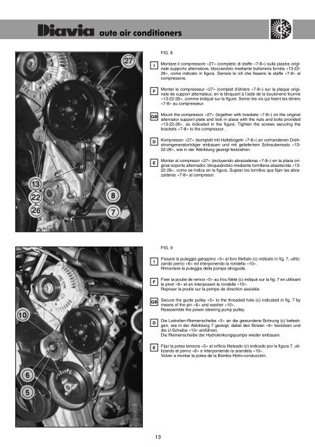
FIG. 8<br />
I<br />
F<br />
GB<br />
D<br />
E<br />
Montare il compressore «27» (completo di staffe «7-8») sulla piastra originale<br />
supporto a<strong>lt</strong>ernatore, bloccandolo mediante bulloneria fornita «13-22-<br />
26», come indicato in figura. Serrare le viti che fissano le staffe «7-8» al<br />
compressore.<br />
Monter le compresseur «27» (complet d’étriers «7-8») sur la plaque originale<br />
de support a<strong>lt</strong>ernateur, en le bloquant à l’aide de la boulonerie fournie<br />
«13-22-26», comme indiqué sur la figure. Serrer les vis qui fixent les étriers<br />
«7-8» au compresseur.<br />
Mount the compressor «27» (together with brackets «7-8») on the original<br />
a<strong>lt</strong>ernator support plate and lock in place with the nuts and bo<strong>lt</strong>s provided<br />
«13-22-26», as indicated in the figure. Tighten the screws securing the<br />
brackets «7-8» to the compressor.<br />
Kompressor «27» (komplett mit Ha<strong>lt</strong>ebügeln «7-8») an vorhandenen Drehstromgeneratorträger<br />
einbauen und mit geliefertem Schraubensatz «13-<br />
22-26», wie in der Abbildung gezeigt festziehen.<br />
Montar el compresor «27» (incluyendo abrazaderas «7-8») en la placa original<br />
soporte a<strong>lt</strong>ernador, bloqueándolo mediante tornilleria abastecida «13-<br />
22-26», como se indica en la figura. Sujetar los tornillos que fijan las abrazaderas<br />
«7-8» al compresor.<br />
FIG. 9<br />
I<br />
F<br />
GB<br />
D<br />
E<br />
Fissare la puleggia galoppino «5» al foro filettato (c) indicato in fig. 7, utilizzando<br />
perno «6» ed interponendo la rondella «10».<br />
Rimontare la puleggia della pompa idroguida.<br />
Fixer la poulie de renvoi «5» au trou filété (c) indiqué sur la fig. 7 en utilisant<br />
le pivot «6» et en interposant la rondelle «10».<br />
Reposer la poulie sur la pompe de direction assistée.<br />
Secure the guide pulley «5» to the threaded hole (c) indicated in fig. 7 by<br />
means of the pin «6» and washer «10».<br />
Reassemble the power steering pump pulley.<br />
Die Leitrollen-Riemenscheibe «5» an die gewundene Bohrung (c) befestigen,<br />
wie in der Abbildung 7 gezeigt, dabei den Bolzen «6» benützen und<br />
die U-Scheibe «10» einführen.<br />
Die Riemenscheibe der Hydrolenkungspumpe wieder einbauen.<br />
Fijar la polea tensora «5» al orificio fileteado (c) indicado por la figura 7, utilizando<br />
el perno «6» e interponiendo la arandela «10».<br />
Volver a montar la polea de la Bomba Hidro-conducción.<br />
13