volkswagen lt 35 2.5 sdi - Giordano Benicchi
volkswagen lt 35 2.5 sdi - Giordano Benicchi
volkswagen lt 35 2.5 sdi - Giordano Benicchi

Create successful ePaper yourself
Turn your PDF publications into a flip-book with our unique Google optimized e-Paper software.
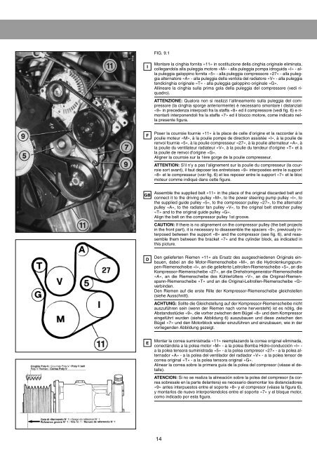
FIG. 9.1<br />
I<br />
Montare la cinghia fornita «11» in sostituzione della cinghia originale eliminata,<br />
collegandola alla puleggia motore «M» - alla puleggia pompa idroguida «I» - alla<br />
puleggia galoppino fornita «5» - alla puleggia compressore «27» - alla puleggia<br />
a<strong>lt</strong>ernatore «A» - alla puleggia della ventola del radiatore «V» - alla puleggia<br />
tendicinghia originale «T» - alla puleggia galoppino originale «G».<br />
Allineare la cinghia sulla prima gola della puleggia del compressore (vedi riquadro).<br />
ATTENZIONE: Qualora non si realizzi l’allineamento sulla puleggia del compressore<br />
(la cinghia sporge anteriormente) è necessario smontare i distanziali<br />
«9» in precedenza interposti fra la staffa «8» ed il compressore (vedi fig. 6) e rimontarli<br />
interponendoli fra la staffa «7» ed il blocco motore, come indicato nella<br />
presente figura.<br />
F<br />
Poser la courroie fournie «11» à la place de celle d’origine et la raccorder à la<br />
poulie moteur «M», à la poulie pompe de direction assistée «I», à la poulie de<br />
renvoi fournie «5», à la poulie compresseur «27», à la poulie a<strong>lt</strong>ernateur «A», à<br />
la poulie du ventilateur radiateur «V», à la poulie du tendeur d’origine «T» et à<br />
la poulie de renvoi d’origine «G».<br />
Aligner la courroie sur la 1ère gorge de la poulie compresseur.<br />
ATTENTION: S’il n’y a pas l’alignement sur la poulie du compresseur (la courroie<br />
sort avant), il faut deposer les entretoises «9» interposées entre le support<br />
«8» et le compresseur (voir fig. 6) et les reposer entre le support «7» et le bloc<br />
moteur comme indiqué dans cette figure.<br />
GB<br />
Assemble the supplied be<strong>lt</strong> «11» in the place of the original discarded be<strong>lt</strong> and<br />
connect it to the driving pulley «M», to the power steering pump pulley «I», to<br />
the supplied guide pulley «5», to the compressor pulley «27», to the a<strong>lt</strong>ernator<br />
pulley «A», to the radiator fan pulley «V», to the original be<strong>lt</strong> stretcher pulley<br />
«T» and to the original guide pulley «G».<br />
Align the be<strong>lt</strong> on the compressor pulley 1st groove.<br />
CAUTION: If there is no alignement on the compressor pulley (the be<strong>lt</strong> projects<br />
in the front part), it is necessary to disassemble the spacers «9», previously interposed<br />
between the support «8» and the compressor (see fig. 6), and reassemble<br />
them between the bracket «7» and the cylinder block, as indicated in<br />
this picture.<br />
D<br />
Den gelieferten Riemen «11» als Ersatz des ausgeschiedenen Originals einbauen,<br />
dabei an die Motor-Riemenscheibe «M», an die Hydrolenkungspumpen-Riemenscheibe<br />
«I», an die gelieferte Leitrollen-Riemenscheibe «5», an die<br />
Kompressor-Riemenscheibe «27», an die Drehstromgenerator-Riemenscheibe<br />
«A», an die Riemenscheibe des Kühlerlüfters «V», an die Original-Riemenspann-Riemenscheibe<br />
«T» und an die Original-Leitrollen-Riemenscheibe «G»<br />
verbinden.<br />
Den Riemen auf die erste Rille der Kompressor-Riemenscheibe gleichstellen<br />
(siehe Ausschnitt).<br />
ACHTUNG: Sol<strong>lt</strong>e die Gleichstellung auf der Kompressor-Riemenscheibe nicht<br />
auszuführen sein (wenn der Riemen nach vorne herversteht) ist es nötig, die<br />
Abstandsstücke «9», die vorher zwischen dem Bügel «8» und dem Kompressor<br />
eingeführt wurden (siehe Abbildung 6) auszubauen und diese zwischen den<br />
Bügel «7» und den Motorblock wieder einzuführen und einzubauen, wie in der<br />
vorliegenden Abbildung gezeigt.<br />
E<br />
Montar la correa suministrada «11» reemplazando la correa original eliminada,<br />
conectándola a la polea motor «M» - a la polea Bomba Hidro-conducción «I» -<br />
a la polea tensora suministrada «5» - a la polea compresor «27» - a la polea a<strong>lt</strong>ernador<br />
«A» - a la polea del ventilador del radiador «V» - a la polea tensor de<br />
correa original «T» - a la polea tensora original «G».<br />
Alinear la correa sobre la primera guía de la polea del compresor (véase el detalle).<br />
ATENCION: Si no se realiza la alineación sobre la polea del compresor (la correa<br />
sobresale en la parte delantera) es necesario desmontar los distanciadores<br />
«9» antes interpuestos entre el soporte «8» y el compresor (véase la figura 6),<br />
y montarlos de nuevo interponiendolos entre el soporte «7» y el bloque motor,<br />
como indicado por esta figura.<br />
14