Gebrauchsanleitung Durchsicht-Thermostate CT 53 CT 53 TT CT 53 ...
Gebrauchsanleitung Durchsicht-Thermostate CT 53 CT 53 TT CT 53 ...
Gebrauchsanleitung Durchsicht-Thermostate CT 53 CT 53 TT CT 53 ...

Create successful ePaper yourself
Turn your PDF publications into a flip-book with our unique Google optimized e-Paper software.
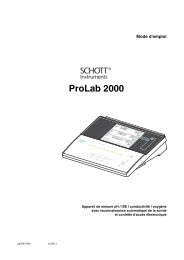
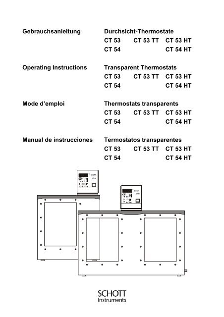
<strong>Gebrauchsanleitung</strong><br />
<strong>Durchsicht</strong>-<strong>Thermostate</strong><br />
<strong>CT</strong> <strong>53</strong> <strong>CT</strong> <strong>53</strong> <strong>TT</strong> <strong>CT</strong> <strong>53</strong> HT<br />
<strong>CT</strong> 54<br />
<strong>CT</strong> 54 HT<br />
Operating Instructions<br />
Transparent Thermostats<br />
<strong>CT</strong> <strong>53</strong> <strong>CT</strong> <strong>53</strong> <strong>TT</strong> <strong>CT</strong> <strong>53</strong> HT<br />
<strong>CT</strong> 54<br />
<strong>CT</strong> 54 HT<br />
Mode d’emploi<br />
Thermostats transparents<br />
<strong>CT</strong> <strong>53</strong> <strong>CT</strong> <strong>53</strong> <strong>TT</strong> <strong>CT</strong> <strong>53</strong> HT<br />
<strong>CT</strong> 54<br />
<strong>CT</strong> 54 HT<br />
Manual de instrucciones<br />
Termostatos transparentes<br />
<strong>CT</strong> <strong>53</strong> <strong>CT</strong> <strong>53</strong> <strong>TT</strong> <strong>CT</strong> <strong>53</strong> HT<br />
<strong>CT</strong> 54<br />
<strong>CT</strong> 54 HT
Seite / Page/ Page / Página<br />
<strong>Gebrauchsanleitung</strong> ...................................................................................... 1 .......... 28<br />
Wichtige Hinweise: Die <strong>Gebrauchsanleitung</strong> vor der ersten Inbetriebnahme der <strong>Durchsicht</strong>-<strong>Thermostate</strong><br />
<strong>CT</strong> <strong>53</strong>, <strong>CT</strong> <strong>53</strong> HT, <strong>CT</strong> <strong>53</strong> <strong>TT</strong>, <strong>CT</strong> 54, <strong>CT</strong> 54 HT bitte sorgfältig lesen und beachten. Aus Sicherheitsgründen<br />
dürfen die <strong>Durchsicht</strong>-<strong>Thermostate</strong> <strong>CT</strong> <strong>53</strong>, <strong>CT</strong> <strong>53</strong> HT, <strong>CT</strong> <strong>53</strong> <strong>TT</strong>, <strong>CT</strong> 54, <strong>CT</strong> 54 HT ausschließlich für die in<br />
dieser Gebrauchs-anleitung beschriebenen Zwecke eingesetzt werden.<br />
Bitte beachten Sie auch die <strong>Gebrauchsanleitung</strong>en für die anzuschließenden Geräte.<br />
Alle in dieser <strong>Gebrauchsanleitung</strong> enthaltenen Angaben sind zum Zeitpunkt der Drucklegung gültige Daten.<br />
Es können jedoch von SCHO<strong>TT</strong> Instruments GmbH sowohl aus technischen und kaufmännischen<br />
Gründen, als auch aus der Notwendigkeit heraus, gesetzliche Bestimmungen der verschiedenen Länder zu<br />
berücksichtigen, Ergänzungen an den <strong>Durchsicht</strong>-<strong>Thermostate</strong>n <strong>CT</strong> <strong>53</strong>, <strong>CT</strong> <strong>53</strong> HT, <strong>CT</strong> <strong>53</strong> <strong>TT</strong>, <strong>CT</strong> 54,<br />
<strong>CT</strong> 54 HT vorgenommen werden, ohne daß die beschriebenen Eigenschaften beeinflußt werden.<br />
Operating Instructions ................................................................................ 29 .......... 56<br />
Important notes: Before initial operation of the Tranparent Thermostats <strong>CT</strong> <strong>53</strong>, <strong>CT</strong> <strong>53</strong> HT, <strong>CT</strong> <strong>53</strong> <strong>TT</strong>, <strong>CT</strong> 54,<br />
<strong>CT</strong> 54 HT please carefully read and observe the operating instructions. For safety reasons the Transparent<br />
Thermostats <strong>CT</strong> <strong>53</strong>, <strong>CT</strong> <strong>53</strong> HT, <strong>CT</strong> <strong>53</strong> <strong>TT</strong>, <strong>CT</strong> 54, <strong>CT</strong> 54 HT may only be used for the purposes described<br />
in these present operating instructions.<br />
Please also observe the operating instructions for the units to be connected.<br />
All specifications in this instruction manual are guidance values which are valid at the time of printing.<br />
However, for technical or commercial reasons or in the necessity to comply with the statuary stipulations of<br />
various countries, SCHO<strong>TT</strong> Instruments GmbH may perform additions to the Transparent Thermostats<br />
<strong>CT</strong> <strong>53</strong>, <strong>CT</strong> <strong>53</strong> HT, <strong>CT</strong> <strong>53</strong> <strong>TT</strong>, <strong>CT</strong> 54, <strong>CT</strong> 54 HT without changing the described properties.<br />
Mode d’emploi............................................................................................... 57 .......... 84<br />
Instructions importantes: Prière de lire et d’observer attentivement le mode d'emploi avant la première mise<br />
en marche des thermostats transparents <strong>CT</strong> <strong>53</strong>, <strong>CT</strong> <strong>53</strong> HT, <strong>CT</strong> <strong>53</strong> <strong>TT</strong>, <strong>CT</strong> 54, <strong>CT</strong> 54 HT. Pour des raisons<br />
de sécurité, les thermostats transparents <strong>CT</strong> <strong>53</strong>, <strong>CT</strong> <strong>53</strong> HT, <strong>CT</strong> <strong>53</strong> <strong>TT</strong>, <strong>CT</strong> 54, <strong>CT</strong> 54 HT pourront être<br />
utilisés exclusivement pour les usages décrits dans ce présent mode d'emploi.<br />
Nous vous prions de respecter également les modes d'emploi pour les appareils à connecter.<br />
Toutes les indications comprises dans ce mode d’emploi sont données à titre indicatif au moment de<br />
l'impression. Pour des raisons techniques et/ou commerciales ainsi qu'en raison des dispositions légales<br />
existantes dans les différents pays, SCHO<strong>TT</strong> Instruments GmbH se réserve le droit d'effectuer des<br />
suppléments concernant les thermostats transparents <strong>CT</strong> <strong>53</strong>, <strong>CT</strong> <strong>53</strong> HT, <strong>CT</strong> <strong>53</strong> <strong>TT</strong>, <strong>CT</strong> 54, <strong>CT</strong> 54 HT qui<br />
n’influencent pas les caractéristiques décrits.<br />
Manual de instrucciones .............................................................................. 85 ........ 112<br />
Instrucciones importantes: Lea atentamente las instrucciones de puesta en marcha de los Termostatos<br />
Transparentes <strong>CT</strong> <strong>53</strong>, <strong>CT</strong> <strong>53</strong> HT, <strong>CT</strong> <strong>53</strong> <strong>TT</strong>, <strong>CT</strong> 54, <strong>CT</strong> 54 HT. Por razones de seguridad, los Termostatos<br />
Transparentes <strong>CT</strong> <strong>53</strong>, <strong>CT</strong> <strong>53</strong> HT, <strong>CT</strong> <strong>53</strong> <strong>TT</strong>, <strong>CT</strong> 54, <strong>CT</strong> 54 HT deben ser exclusivamente empleados para<br />
los fines descritos en este manual de instrucción. Por favor, tenga en cuenta también antes de conectar los<br />
equipos , los manuales de instrucciones. Todas las informaciones contenidas en este manual de<br />
instrucciones, son datos que están en vigor en el momento de la impresión. Por motivos técnicos y<br />
comerciales, así como también por la necesidad de respetar las normas legales existentes en los<br />
diferentes países , SCHO<strong>TT</strong> Instruments GmbH puede efectuar modificaciones en los Termostatos<br />
Transparentes <strong>CT</strong> <strong>53</strong>, <strong>CT</strong> <strong>53</strong> HT, <strong>CT</strong> <strong>53</strong> <strong>TT</strong>, <strong>CT</strong> 54, <strong>CT</strong> 54 HT sin cambiar las características descritas.
Inhaltsverzeichnis<br />
Qualitätssicherung ........................................................................................................................................ 2<br />
Kontakte zu SCHO<strong>TT</strong> Instruments GmbH.................................................................................................... 2<br />
Sicherheitshinweise ...................................................................................................................................... 3<br />
KONFORMITÄTSERKLÄRUNG................................................................................................................... 6<br />
1. Technische Daten <strong>Durchsicht</strong>-<strong>Thermostate</strong> <strong>CT</strong> <strong>53</strong>, <strong>CT</strong> <strong>53</strong> HT, <strong>CT</strong> <strong>53</strong> <strong>TT</strong>, <strong>CT</strong> 54, <strong>CT</strong> 54 HT................. 7<br />
1.1. Technische Daten Einhänge-Thermostat <strong>CT</strong> 52 ............................................................................. 7<br />
1.2. Technische Daten <strong>Durchsicht</strong>bäder <strong>CT</strong> <strong>53</strong>, <strong>CT</strong> <strong>53</strong> HT, <strong>CT</strong> <strong>53</strong> <strong>TT</strong>, <strong>CT</strong> 54, <strong>CT</strong> 54 HT ..................... 9<br />
2. Bedienungs- und Funktionselemente .................................................................................................... 10<br />
2.1. Frontansicht Einhängethermostat <strong>CT</strong> 52 ....................................................................................... 11<br />
2.2. Rückansicht Einhängethermostat <strong>CT</strong> 52 ....................................................................................... 11<br />
2.3. Gesamtansicht <strong>Durchsicht</strong>-<strong>Thermostate</strong> <strong>CT</strong> <strong>53</strong>, <strong>CT</strong> <strong>53</strong> HT, <strong>CT</strong> <strong>53</strong> <strong>TT</strong>.......................................... 12<br />
2.4. Gesamtansicht <strong>Durchsicht</strong>-Thermostat <strong>CT</strong> 54, <strong>CT</strong> 54 HT............................................................. 12<br />
3. Auspacken und Überprüfen ................................................................................................................... 13<br />
4. Beschreibung ......................................................................................................................................... 13<br />
5. Vorbereitungen ...................................................................................................................................... 13<br />
5.1. Badflüssigkeiten ............................................................................................................................. 13<br />
5.2. Befüllen / Entleeren........................................................................................................................ 14<br />
5.3. Arbeiten mit Mikro-Ubbelohde Viskosimeter mit TC-Sensoren ..................................................... 14<br />
5.4. Umbau für den Einsatz von AVS-Meßstativen oder Handmeßeinsätzen...................................... 15<br />
5.5. Gegenkühlung................................................................................................................................ 16<br />
5.6. Magnetrührer (Option).................................................................................................................... 17<br />
6. Inbetriebnahme ...................................................................................................................................... 18<br />
6.1. Netzanschluß ................................................................................................................................. 18<br />
6.2. Einschalten / Start - Stop ............................................................................................................... 18<br />
6.3. Temperatureinstellung ................................................................................................................... 19<br />
6.4. Warnfunktionen .............................................................................................................................. 19<br />
6.5. Sicherheitstemperatur-Einstellung (mit Abschaltfunktion) ............................................................. 20<br />
7. Mögliche Störursachen / Alarm-Meldungen .......................................................................................... 21<br />
8. Sicherheitsanweisungen........................................................................................................................ 22<br />
9. ATC - Absolute Temperature Calibration .............................................................................................. 22<br />
10. Elektrische Anschlußmöglichkeiten..................................................................................................... 23<br />
11. Fernsteuerbetrieb, Laborautomatisierung........................................................................................... 24<br />
11.1. Vorbereitung zur Fernsteuerung .................................................................................................... 24<br />
11.2. Kommunikation mit PC................................................................................................................... 25<br />
11.3. Befehlsübersicht............................................................................................................................. 26<br />
11.4. Statusmeldungen ........................................................................................................................... 26<br />
11.5. Fehlermeldungen ........................................................................................................................... 27<br />
12. Reinigung des Gerätes........................................................................................................................ 28<br />
13. Instandhaltung..................................................................................................................................... 28<br />
14. Entsorgen ............................................................................................................................................ 28<br />
1
Qualitätssicherung<br />
Qualitätssicherung<br />
Sehr geehrter Kunde,<br />
SCHO<strong>TT</strong> Instruments GmbH arbeitet im Rahmen eines Qualitäts-<br />
Management-Systems nach DIN ISO 9001 / EN 29001. Damit sind<br />
die organisatorischen Voraussetzungen geschaffen, daß Produkte<br />
entsprechend den Erwartungen unserer Kunden entwickelt,<br />
hergestellt und betreut werden. Damit unser Q-System funktioniert,<br />
wird es durch interne und externe Auditoren ständig überprüft.<br />
Bitte teilen Sie uns mit, wenn Sie trotz unserer Sorgfalt Mängel am<br />
Produkt feststellen. Auch diese möchten wir in Zukunft vermeiden.<br />
Kontakte zu SCHO<strong>TT</strong> Instruments GmbH<br />
Bitte wenden Sie sich bei Rückfragen an uns oder an unsere<br />
Partnerfirma, die Ihnen das Gerät geliefert hat.<br />
SCHO<strong>TT</strong> Instruments GmbH<br />
Postfach 2443<br />
D-55114 Mainz<br />
Hattenbergstrasse 10<br />
D-55122 Mainz<br />
Telefon +49 61 31 / 66 51 11<br />
Telefax +49 61 31 / 66 50 01<br />
E-mail: avs@schottinstruments.com<br />
www.schottinstruments.com<br />
SCHO<strong>TT</strong> Instruments GmbH<br />
D55122 Mainz<br />
Typ <strong>CT</strong> <strong>53</strong> Nr 000000<br />
230 V /50 Hz 2070 VA<br />
Made in Germany<br />
In jedem Fall sollten Sie aber bei allen Rückfragen zum Gerät<br />
bitte diese Angaben machen:<br />
- Typenbezeichnung an der Frontseite und am Typenschild auf<br />
der Rückseite.<br />
2
Sicherheitshinweise<br />
Sicherheitshinweise<br />
Diese Hinweise geben wir Ihnen, um auf Risiken aufmerksam zu<br />
machen, die nur Sie erkennen, vermeiden oder beherrschen<br />
können. Sie sollen dazu dienen, Sie in Ihrem<br />
Sicherheitsbewußtsein zu unterstützen.<br />
Bei der Entwicklung und Fertigung haben wir hohe Qualitätsansprüche<br />
an uns und an die Geräte gestellt. Jedes Gerät<br />
entspricht den einschlägigen Sicherheitsbestimmungen.<br />
Die sachgemäße Handhabung und der richtige Gebrauch liegt<br />
aber allein bei Ihnen.<br />
Deshalb diese Hinweise:<br />
Lesen Sie unbedingt diese Gebrauchsanweisung durch! Sie<br />
enthält wichtige Informationen zum Anschluß an das örtliche<br />
Stromnetz, zum bestimmungsgemäßen Gebrauch und zur<br />
sicheren Handhabung.<br />
Achten Sie bereits beim Auspacken auf Transportschäden. Zur<br />
Schadensregulierung wenden Sie sich zweckmäßigerweise an<br />
den Spediteur oder Lieferer. Versuchen Sie aber auf keinen<br />
Fall, ein beschädigtes Gerät in Betrieb zu nehmen, bevor der<br />
Schaden behoben ist oder Sie sich über die<br />
Schadensauswirkung vergewissert haben.<br />
Sorgen Sie dafür, daß diese Anleitung für jeden Benutzer<br />
immer griffbereit ist.<br />
Benutzen Sie das Gerät ausschließlich für den vorgesehenen<br />
Zweck.<br />
Lassen Sie Reparaturen, Änderungen oder Eingriffe nur von<br />
Fachkräften durchführen. Durch eine unsachgemäße<br />
Reparatur kann erheblicher Schaden entstehen. Für<br />
Reparaturen steht Ihnen der SCHO<strong>TT</strong> Instruments GmbH<br />
Service zur Verfügung.<br />
Bedienen Sie das Gerät nicht mit feuchten oder öligen<br />
Händen.<br />
Bespritzen Sie den Gerätekopf nicht mit Wasser, tauchen Sie<br />
ihn nicht in Wasser ein.<br />
3
Sicherheitshinweise<br />
Reinigen Sie das Gerät nicht mit Lösemittel (Brandgefahr!) -<br />
ein feuchtes Tuch, mit haushaltsüblichem Reinigungsmittel<br />
getränkt, reicht häufig aus.<br />
Beachten Sie, daß das Gerät nicht gemäß IEC 601-1<br />
konstruiert ist, d. h. es darf nicht in medizinisch genutzten<br />
Räumen und/oder Patientenumgebung aufgestellt werden.<br />
Viele Teile des Gerätes sind funktionsbedingt heiß - es besteht<br />
Verbrennungsgefahr!<br />
Sorgen Sie für einen geeigneten Berührungsschutz.<br />
Bewegen Sie das Gerät nicht vom Aufstellungsort weg,<br />
während es in Betrieb ist oder gar heiß ist. Es besteht<br />
Verbrennungsgefahr!<br />
Verwenden Sie nur die von uns empfohlene Badflüssigkeit.<br />
Zum bestimmungsgemäßen Gebrauch des <strong>Thermostate</strong>n<br />
gehört es auch, Kapillarviskosemeter, Reagenzgläser, Erlenmeyerkolben<br />
o. ä. direkt im <strong>Thermostate</strong>n zu temperieren, d. h.<br />
einzutauchen.<br />
Wir wissen nicht, welche Substanzen diese Gefäße enthalten. Viele<br />
Substanzen sind:<br />
• entzündlich, brennbar oder explosiv<br />
• gesundheitsschädlich<br />
• umweltgefährdend<br />
also : gefährlich.<br />
Sie allein sind für den Umgang mit diesen Stoffen verantwortlich!<br />
Unser Ratschlag:<br />
• Ziehen Sie im Zweifelsfall einen Sicherheitsbeauftragten zu<br />
Rate.<br />
• Lesen Sie das „EU-Sicherheitsdatenblatt“ des Produktherstellers<br />
oder Lieferanten.<br />
• Informieren Sie sich über die Gefahrstoffverordnung.<br />
• Beachten Sie die „Richtlinien für Laboratorien“ (Richtlinie Nr. 12<br />
der BG Chemie).<br />
4
Sicherheitshinweise<br />
<br />
<br />
<br />
Zur Sicherheit des Gerätebenutzers sind die folgenden<br />
Schutzmaßnahmen getroffen worden:<br />
• Schutzklasse I nach VDE 0106 T1 (IEC <strong>53</strong>6) d. h. Schutz gegen<br />
gefährliche Körperströme dadurch, daß Teile die<br />
berührungsgefährlich werden können, mit dem Schutzleiter der<br />
Installation verbunden sind.<br />
• Geräte nur an Netzsteckdosen mit Schutzkontakt anschließen.<br />
• Schutzart IP 20 nach EN 60529,<br />
d. h. bezüglich des Berührungs und Fremdkörperschutzes ist<br />
sichergestellt, daß Fremdkörper mit einer Dicke oder einem<br />
Durchmesser von mehr als 12 mm nicht eindringen können.<br />
Es ist kein besonderer Schutz gegen das Eindringen von Wasser<br />
und Staub getroffen. Daher das Gerät vor Spritzwasser<br />
schützen und nicht in staubiger Umgebung aufstellen.<br />
Keine Drähte oder Werkzeuge in die vorhandenen Öffnungen<br />
stecken.<br />
Trennung vom Netz ist erforderlich, wenn:<br />
- Gefahren, die vom Netz ausgehen, abgewendet werden sollen,<br />
- Reinigungsarbeiten durchgeführt werden,<br />
- in der Servicewerkstatt Wartungs - oder Reparaturarbeiten<br />
ausgeführt werden.<br />
Sichere elektrische Trennung heißt:<br />
Netzstecker ziehen!<br />
5
KONFORMITÄTSERKLÄRUNG<br />
KONFORMITÄTSERKLÄRUNG<br />
DECLARATION OF CONFORMITY<br />
DÉCLARATION DE CONFORMITÉ<br />
Wir erklären in alleiniger<br />
Verantwortung, daß die<br />
Produkte<br />
<strong>Durchsicht</strong>-<br />
<strong>Thermostate</strong><br />
<strong>CT</strong> <strong>53</strong><br />
<strong>CT</strong> <strong>53</strong> HT<br />
<strong>CT</strong> <strong>53</strong> <strong>TT</strong><br />
<strong>CT</strong> 54<br />
<strong>CT</strong> 54 HT<br />
auf die sich diese<br />
Erklärung bezieht,<br />
übereinstimmt mit den<br />
Normen<br />
We declare under our sole<br />
responsibility that the<br />
products<br />
Transparent<br />
Thermostats<br />
<strong>CT</strong> <strong>53</strong><br />
<strong>CT</strong> <strong>53</strong> HT<br />
<strong>CT</strong> <strong>53</strong> <strong>TT</strong><br />
<strong>CT</strong> 54<br />
<strong>CT</strong> 54 HT<br />
to which this declaration<br />
relates are in conformity<br />
with the standards<br />
Nous déclarons sous notre<br />
seule responsabilité que<br />
les produits<br />
Thermostats<br />
transparents<br />
<strong>CT</strong> <strong>53</strong><br />
<strong>CT</strong> <strong>53</strong> HT<br />
<strong>CT</strong> <strong>53</strong> <strong>TT</strong><br />
<strong>CT</strong> 54<br />
<strong>CT</strong> 54 HT<br />
auquels se réfère cette<br />
déclaration est conforme<br />
aux normes<br />
DIN 58 966<br />
und / and / et<br />
DIN 12 876, Sicherheitsklasse III<br />
und mit dem normativen<br />
Dokument<br />
and the normative<br />
document<br />
et au document normatif<br />
Technische Daten<br />
<strong>Durchsicht</strong>-<strong>Thermostate</strong> <strong>CT</strong> <strong>53</strong>, <strong>CT</strong> <strong>53</strong> HT, <strong>CT</strong> <strong>53</strong> <strong>TT</strong>, <strong>CT</strong>54, <strong>CT</strong> 54 HT<br />
10. Mai 2001<br />
SCHO<strong>TT</strong> Instruments GmbH<br />
Hattenbergstrasse 10<br />
D-55122 Mainz<br />
Deutschland, Germany, Allemagne<br />
10. Mai, May 10, 10. Mai 2001<br />
AGQSF 0000-A052-01/ 060117<br />
6
Technische Daten <strong>Durchsicht</strong>-<strong>Thermostate</strong> <strong>CT</strong> <strong>53</strong>, <strong>CT</strong> <strong>53</strong> HT, <strong>CT</strong> <strong>53</strong> <strong>TT</strong>, <strong>CT</strong> 54, <strong>CT</strong> 54 HT<br />
1. Technische Daten <strong>Durchsicht</strong>-<strong>Thermostate</strong> <strong>CT</strong> <strong>53</strong>, <strong>CT</strong> <strong>53</strong> HT,<br />
<strong>CT</strong> <strong>53</strong> <strong>TT</strong>, <strong>CT</strong> 54, <strong>CT</strong> 54 HT<br />
(Stand 10. Mai 2001)<br />
1.1. Technische Daten Einhänge-Thermostat <strong>CT</strong> 52<br />
CE-Zeichen:<br />
EU-Richtlinie 89/336/EWG (elektromagnetische Kompatibilität);<br />
Normen EN 50 081 Teil 2, EN 50 082 Teil 2<br />
Nach der Richtlinie 73/23/EWG des Rates zuletzt geändert durch Richtlinie<br />
93/68/EWG (Niederspannungsrichtlinie)<br />
Prüfgrundlage nach Norm EN 61 010-1<br />
Ursprungsland:<br />
Made in Germany<br />
Temperaturbereiche: <strong>CT</strong><strong>53</strong> / <strong>CT</strong><strong>53</strong> <strong>TT</strong> <strong>CT</strong><strong>53</strong> HT<br />
<strong>CT</strong>54 <strong>CT</strong>54HT<br />
Betriebstemperaturbereiche<br />
<strong>CT</strong><strong>53</strong>/54 mit zusätzlicher Kühlung [°C]: +5 ... + 102 +5 ... +150<br />
<strong>CT</strong><strong>53</strong> <strong>TT</strong> mit zusätzlicher Kühlung [°C]: -40 ... + 102 -------------<br />
Arbeitstemperaturbereich nach DIN 58 966<br />
(bei 20°C Umgebungstemperatur) [°C]: + 30 ... + 102 + 30 ... + 150<br />
mit Leitungswasserkühlung * [°C]: + 20 ... + 102 + 20 ... + 150<br />
mit Durchflußkühler CK 300 (Option) [°C]: + 5 ... + 102 + 5 ... + 150<br />
<strong>CT</strong><strong>53</strong> <strong>TT</strong> mit separatem<br />
Kälte-Umwälzthermostat (Option) [°C]: - 40 ... + 102 -------------<br />
Temperaturkonstanz [K]: ± 0,01<br />
Temperaturdrift bei Änderungen der<br />
Umgebungstemperatur: max.0,002K/1°C<br />
bei einem Umgebungstemperaturbereich von +5 ... 40°C<br />
Heizleistung: bei 230 V, [VA]: 2000; auf Bestellung 115 V, [VA]: 1000<br />
Pumpe: Druck/Förderstrom max. [hPa / I/min]: 250/10<br />
Regelung:<br />
PID-Regelung<br />
Anschlüsse:<br />
mechanisch:<br />
1. Schlauchanschlüsse 2 x Ø 12 mm für den Betrieb mit dem<br />
Durchflußkühler z.B. CK 300<br />
2. Kühlschlangenanschlüsse 2 x Ø 8 mm für die Kühlung mit Leitungswasser<br />
elektrisch:<br />
1. 5-polige DIN-Buchse mit Schraubgewinde für Steuerkabelanschluß zum<br />
Durchflußkühler CK 300<br />
2. 9-polige Subminiatur-D-Buchse für RS-232-C-Schnittstelle<br />
* bei Verwendung der Kühlschlange kann eine untere Betriebstemperatur von ca. 3 °C oberhalb der<br />
jeweiligen Kühlwasser-Temperatur erreicht werden.<br />
7
Technische Daten <strong>Durchsicht</strong>-<strong>Thermostate</strong> <strong>CT</strong> <strong>53</strong>, <strong>CT</strong> <strong>53</strong> HT, <strong>CT</strong> <strong>53</strong> <strong>TT</strong>, <strong>CT</strong> 54, <strong>CT</strong> 54 HT<br />
Datenübertragung:<br />
Schnittstelle: bidirektionale serielle Schnittstelle nach EIA RS232C<br />
Datenformat: wählbar<br />
Baudrate: 1200, 2400, 4800 oder 9600<br />
Parität: no / odd / even<br />
Wortlänge: 7 Daten-Bits<br />
Stopbit: 1<br />
Protokoll: <strong>CT</strong>S/RTS: abschaltbar<br />
Netzspannung: 230 V~, 50 Hz; auf Bestellung 115 V~, 60 Hz<br />
Leistungsaufnahme: bei 230 V, [VA]: 2070; bei 115 V, [VA]: 1070<br />
Abmessungen: Gesamtabmessungen mit Heiz-, Kühlschlange und Knickschutz für<br />
Netzanschlußkabel: B x T x H [cm]: 38 x 26 x 34<br />
Gehäuseabmessungen ab Badoberkante ohne Knickschutz für<br />
Netzanschlußkabel: B x T x H [cm]: 12 x 15,5 x 14,5<br />
Gewicht: [kg]: ca. 5<br />
Klima:<br />
Umgebungstemperatur: + 10 ... + 40°C (für Betrieb und Lagerung)<br />
Luftfeuchtigkeit nach DIN EN 61 010, Teil 1:<br />
maximale relative Feuchte 80 % für Temperaturen bis 31°C,<br />
linear abnehmend bis 50 % relative Feuchte bei einer Temperatur von 40°C<br />
Sicherheitseinrichtungen:<br />
Übertemperatur-Begrenzer: variabel einstellbar [°C]: + 20 .. + 160<br />
Unterniveau-Begrenzer: Schaltpunkt fest eingestellt<br />
Gerätesicherheit: entspricht Schutzklasse III nach DIN 12 876<br />
Schutzart: IP 20 nach EN 60 529<br />
Stromversorgung:<br />
entspricht der Schutzklasse I nach VDE 0106 T1<br />
nicht für den Einsatz in explosionsgefährdeter Umgebung geeignet<br />
8
Technische Daten <strong>Durchsicht</strong>-<strong>Thermostate</strong> <strong>CT</strong> <strong>53</strong>, <strong>CT</strong> <strong>53</strong> HT, <strong>CT</strong> <strong>53</strong> <strong>TT</strong>, <strong>CT</strong> 54, <strong>CT</strong> 54 HT<br />
1.2. Technische Daten <strong>Durchsicht</strong>bäder <strong>CT</strong> <strong>53</strong>, <strong>CT</strong> <strong>53</strong> HT, <strong>CT</strong> <strong>53</strong> <strong>TT</strong>, <strong>CT</strong> 54,<br />
<strong>CT</strong> 54 HT<br />
<strong>CT</strong><strong>53</strong> <strong>CT</strong> 54<br />
Füllmenge: [L]: ca. 15 ca. 27<br />
Abmessungen: B x T x H [cm]: 35,5 x 25 x 37 60,5 x 25 x 37<br />
Gewicht: ohne Badflüssigkeit [kg]: ca. 13.5, ca. 28<br />
<strong>Durchsicht</strong>bad-Werkstoff:<br />
Edelstahl, Isolierglas (Mineralglas)<br />
Badflüssigkeit:<br />
Wasser, Siliconöle, Mineralöle, Polyglykole<br />
Temperaturbereich:<br />
<strong>CT</strong> <strong>53</strong> <strong>TT</strong> [°C]: -40 ... +120<br />
Mit eingebauter <strong>TT</strong>- Sonderkühlschlange in Verbindung mit einem<br />
Kälte-Umwälzthermostat (Option)<br />
<strong>CT</strong> <strong>53</strong>, <strong>CT</strong> 54 [°C]: +5 ... +120<br />
Mit eingebauter Kühlschlange in Verbindung mit Durchflußkühler<br />
CK 300 (Option) oder einem Kälte-Umwälzthermostat (Option)<br />
<strong>CT</strong> <strong>53</strong> HT, <strong>CT</strong> 54 HT [°C]: +5 ... +150<br />
Mit eingebauter Kühlschlange in Verbindung mit Durchflußkühler<br />
CK 300 (Option) oder einem Kälte-Umwälzthermostat (Option)<br />
Ursprungsland:<br />
Made in Germany<br />
9
Bedienungs- und Funktionselemente<br />
2. Bedienungs- und Funktionselemente<br />
Frontseite<br />
1 Netzschalter, beleuchtet<br />
2 Taste Start / Stop<br />
3 Taste-Sollwertanzeige Arbeitstemperatur<br />
4 Taste-Sollwertanzeige Übertemperatur<br />
5 Taste-Sollwertanzeige Untertemperatur<br />
6 MULTI-DISPLAY Temperaturanzeige<br />
Kontroll-Lampe - Heizung<br />
Kontroll-Lampe - Kühlung<br />
Kontroll-Lampe - Alarm<br />
7 Cursor-Tasten (links/rechts)<br />
8 Editier-Tasten (höher/niedriger)<br />
9 Enter-Taste (speichern)<br />
Rückseite<br />
60<br />
100<br />
10<br />
20<br />
140<br />
160<br />
°C Einstellbarer Übertemperaturschutz<br />
(DIN 12876, Sicherheitstemperatur)<br />
11 Gewinde (M10) für Stativstange<br />
12 Netzkabel mit Stecker<br />
13 Anschlußbuchse: Schnittstelle RS 232 C<br />
14 Anschlußbuchse 5-polig: Anschluß für<br />
Durchflußkühler CK 300 über Adapterkabel<br />
10
Bedienungs- und Funktionselemente<br />
2.1. Frontansicht Einhängethermostat <strong>CT</strong> 52<br />
6<br />
°C<br />
4<br />
5<br />
7<br />
8<br />
9<br />
2<br />
3<br />
1<br />
2.2. Rückansicht Einhängethermostat <strong>CT</strong> 52<br />
13<br />
12<br />
RS 232 C<br />
10<br />
20<br />
60<br />
°C<br />
100<br />
140<br />
160<br />
ALARM<br />
14<br />
11<br />
SCHO<strong>TT</strong> Instruments GmbH<br />
D55122 Mainz<br />
Typ <strong>CT</strong> <strong>53</strong> Nr 000000<br />
230 V /50 2070 VA<br />
Made in Germany<br />
11
Bedienungs- und Funktionselemente<br />
2.3. Gesamtansicht <strong>Durchsicht</strong>-<strong>Thermostate</strong> <strong>CT</strong> <strong>53</strong>, <strong>CT</strong> <strong>53</strong> HT, <strong>CT</strong> <strong>53</strong> <strong>TT</strong><br />
<br />
Die <strong>Durchsicht</strong>-<strong>Thermostate</strong> sind betriebsbereit montiert und bestehen je nach Bestellung<br />
im Fall <strong>CT</strong> <strong>53</strong> aus: Einhängethermostat <strong>CT</strong> 52 und <strong>Durchsicht</strong>bad <strong>CT</strong> <strong>53</strong><br />
oder im Fall <strong>CT</strong> <strong>53</strong> HT aus: Einhängethermostat <strong>CT</strong> 52 und <strong>Durchsicht</strong>bad <strong>CT</strong> <strong>53</strong> HT<br />
oder im Fall <strong>CT</strong> <strong>53</strong> <strong>TT</strong> aus: Einhängethermostat <strong>CT</strong> 52 und <strong>Durchsicht</strong>bad <strong>CT</strong> <strong>53</strong> <strong>TT</strong><br />
oder im Fall <strong>CT</strong> 54 aus: Einhängethermostat <strong>CT</strong> 52 und <strong>Durchsicht</strong>bad <strong>CT</strong> 54<br />
oder im Fall <strong>CT</strong> 54 HT aus: Einhängethermostat <strong>CT</strong> 52 und <strong>Durchsicht</strong>bad <strong>CT</strong> 54 HT<br />
2.4. Gesamtansicht <strong>Durchsicht</strong>-Thermostat <strong>CT</strong> 54, <strong>CT</strong> 54 HT<br />
12
Auspacken und Überprüfen<br />
3. Auspacken und Überprüfen<br />
4. Beschreibung<br />
Gerät und Zubehör sollten nach dem Auspacken zuerst auf<br />
Vollständigkeit und eventuelle Transportschäden überprüft werden.<br />
Schon bei beschädigter Umverpackung sollte der Spediteur, die<br />
Bahn oder die Post benachrichtigt werden, damit ein<br />
Schadensprotokoll erstellt werden kann.<br />
5. Vorbereitungen<br />
Die <strong>Durchsicht</strong>-<strong>Thermostate</strong> sind für die Temperierung von Wasser<br />
und Silikonöle vorgesehen.<br />
Die Haupt-Funktionselemente sind Heizer, Umwälzpumpe und<br />
Regelelektronik. Die elektronische PID-Regelung paßt die<br />
Wärmezufuhr automatisch dem erforderlichen Bedarf im Bad an.<br />
Die Bedienung des <strong>Durchsicht</strong>-<strong>Thermostate</strong>n erfolgt über eine<br />
spritzwassergeschützte Folientastatur. Die Mikroprozessortechnik<br />
erlaubt es den Wert für die Arbeitstemperatur sowie die Werte für<br />
die Über- und Untertemperatur-Warnfunktionen einzustellen, zu<br />
speichern und über das MULTI-DISPLAY anzuzeigen.<br />
Der Übertemperaturschutz nach DIN 12876 ist eine vom Regelkreis<br />
unabhängige Sicherheitseinrichtung deren Sicherheitswert auf der<br />
Rückseite des Gerätes eingestellt wird.<br />
Die <strong>Durchsicht</strong>-<strong>Thermostate</strong> dieser Typenreihe entsprechen den<br />
Sicherheitsbestimmungen nach DIN 12 876 (Sicherheitsklasse III),<br />
den mitgeltenden Normen nach DIN 58 966, der EN 61010-1 sowie<br />
den NAMUR-Empfehlungen.<br />
5.1. Badflüssigkeiten<br />
SCHO<strong>TT</strong> Instruments GmbH empfiehlt:<br />
1. Deionisiertes Wasser und Leitungswasser im Verhältnis<br />
1:1 bei 10°dH bis 5:1 bei 30°dH je nach Härtegrad zu<br />
verwenden um Korrosion vorzubeugen.<br />
Betriebstemperaturbereich: 5 °C bis 80 °C<br />
Wichtig:<br />
Beim Einsatz des <strong>Durchsicht</strong>-<strong>Thermostate</strong>n <strong>CT</strong> <strong>53</strong>, <strong>CT</strong> <strong>53</strong> HT,<br />
<strong>CT</strong> <strong>53</strong> <strong>TT</strong> oder <strong>CT</strong> 54 im Probenautomat AVS Pro reduziert<br />
sich der empfohlene Betriebstemperaturbereich bei Wasser auf<br />
10 °C bis 40 °C .<br />
2. Silikonöl bzw. Mineralöl mit maximaler Viskosität von<br />
30 mm 2 x S -1 (<strong>CT</strong> 54 HT 10 mm 2 x S -1 ).<br />
Betriebstemperaturbereich: -40 °C bis 150 °C<br />
3. Ethanol und Polyglykole<br />
Betriebstemperaturbereich: -40 °C bis +10 C°<br />
Sicherheitdatenblatt der eingesetzten Badflüssigkeit beachten, besonders die<br />
Angabe des Flammpunktes.<br />
Der Flammpunkt muß mindestens 20 °C über der Arbeitstemperatur liegen!<br />
13
Vorbereitungen<br />
5.2. Befüllen / Entleeren<br />
Darauf achten, daß keine Badflüssigkeit in das Innere des Einhängethermostaten<br />
<strong>CT</strong> 52 eindringt.<br />
°C<br />
Befüllen<br />
• Die empfohlene Füllhöhe bei Wasser ist die Oberkante des<br />
<strong>Durchsicht</strong>fensters.<br />
• Die empfohlene Füllhöhe für Öl liegt bei 20 mm unterhalb der<br />
Oberkante des <strong>Durchsicht</strong>fensters.<br />
18<br />
17<br />
<strong>CT</strong> 54<br />
Entleeren<br />
• <strong>Durchsicht</strong>-Thermostat mit dem Netzschalter ausschalten.<br />
• Vom Netz trennen.<br />
<strong>CT</strong> <strong>53</strong>:<br />
• Badgefäß entleeren<br />
z. B.: Badflüssigkeit Wasser mit Wasserstrahlpumpe.<br />
<strong>CT</strong> 54:<br />
• Geeignetes Gefäß zur Aufnahme der benutzten Temperierflüssigkeit<br />
unterstellen.<br />
• Ein kurzes Schlauchstück auf den Ablaufstutzen (17) schieben<br />
und das Schlauchende in das Gefäß halten.<br />
• Zum Entleeren Ablaßschraube (18) einige Umdrehungen heraus<br />
drehen.<br />
• Ablaßschraube nach der vollständigen Entleerung wieder<br />
zudrehen.<br />
Badflüssigkeit nicht im heißen Zustand entleeren<br />
5.3. Arbeiten mit Mikro-Ubbelohde Viskosimeter mit TC-Sensoren<br />
Badabdeckung A mit Einsatz für Mikro TC-Viskosimeter.<br />
(Option VZ 7191)<br />
Schraube lösen und Lasche ca. 90° drehen.<br />
Viskosimeter senkrecht bis zum Anschlag einführen.<br />
Lasche zurückdrehen und Schraube wieder fest zudrehen.<br />
Badabdeckung A:<br />
14
Vorbereitungen<br />
5.4. Umbau für den Einsatz von AVS-Meßstativen oder Handmeßeinsätzen<br />
(Lieferzustand)<br />
Badabdeckung B zur Aufnahme von 2 AVS-Meßstativen<br />
oder<br />
2 Handmeßeinsätzen für Kapillarviskosimeter mit<br />
Fixiergestellen<br />
<strong>CT</strong> <strong>53</strong>, <strong>CT</strong> <strong>53</strong> <strong>TT</strong>, <strong>CT</strong> <strong>53</strong> HT<br />
Zentriereinsatz für AVS-Meßstative durch die Badöffnung auf<br />
den Badboden legen und an die Anlegekanten A schieben.<br />
A<br />
A<br />
Spannwinkel an die Wand schieben und beide Schrauben fest<br />
zudrehen.<br />
Der Zentriereinsatz ist jetzt am Badboden befestigt.<br />
Der Einsatz für die Badabdeckung wird mit sechs Schrauben<br />
festgeschraubt.<br />
In jede der beiden Öffnungen kann ein AVS-Meßstativ eingebracht<br />
und auf den Badboden gestellt werden.<br />
Handmeßeinsätze für Viskosimeter bei Bedarf in Öffnung einhängen.<br />
Viskosimeter mit Fixiergestellen einsetzen, siehe hierzu entsprechende<br />
<strong>Gebrauchsanleitung</strong> der Kapillarviskosimeter.<br />
Unbenutzte Meßstelle mit einem Baddeckel verschließen<br />
<strong>CT</strong> 54:<br />
2 Stück Badabdeckung B zur Aufnahme von 2 AVS-Meßstativen<br />
und<br />
2 Handmeßeinsätzen für Kapillarviskosimeter mit Fixiergestellen<br />
15
Vorbereitungen<br />
5.5. Gegenkühlung<br />
40<br />
20<br />
80<br />
120<br />
RS 232 C<br />
14<br />
°C ALARM<br />
SCHO<strong>TT</strong> Instrument GmbH<br />
D65719 Hofheim/Ts.<br />
Typ <strong>CT</strong> 52 Nr 000000<br />
230 V /50 Hz 2070 VA<br />
KL 2 DIN 12879<br />
Made in Germany<br />
15<br />
16a<br />
16b<br />
15<br />
Anschluß an Kühlwasser<br />
Für Arbeiten nahe der Umgebungstemperatur wird der Anschluß der<br />
Kühlschlange an das Kühlwasser erforderlich.<br />
• Kühlschlange mit Hilfe von Schläuchen für den Zulauf an das<br />
Kühlwasser anschließen und den Rücklauf in den Abfluß leiten.<br />
• Zur Kompensierung der Eigentemperatur genügt im allgemeinen<br />
ein Kühlwasserstrom von 100 ml/min.<br />
Empfehlung: Einen Durchflußkonstanthalter verwenden.<br />
15 Kühlschlangenanschlüsse 2 x Ø 8 mm für die Kühlung mit<br />
Leitungswasser<br />
Externe Kühlaggregate<br />
Empfohlen in Verbindung mit <strong>CT</strong><strong>53</strong>, <strong>CT</strong>54, <strong>CT</strong><strong>53</strong> HT und <strong>CT</strong>54 HT<br />
• Mit dem Durchflußkühler CK 300 aus dem SCHO<strong>TT</strong><br />
Instruments GmbH Programm kann das Badmedium auf<br />
niedrigere Temperaturen abgesenkt bzw. der <strong>Durchsicht</strong>-<br />
Thermostat unabhängig vom Kühlwasser gemacht werden.<br />
Montage und Verwendung sind ausführlich in der <strong>Gebrauchsanleitung</strong><br />
des Durchflußkühler CK 300 beschrieben.<br />
16a Pumpenanschluß: Vorlauf<br />
16b Pumpenanschluß: Rücklauf<br />
Schlauchanschlüsse 2 x Ø 12 mm für den Betrieb mit dem<br />
Durchflußkühler z.B. CK 300<br />
14 5-polige DIN-Buchse mit Schraubgewinde für Steuerkabelanschluß<br />
zum Durchflußkühler CK 300<br />
Empfohlen in Verbindung mit <strong>CT</strong><strong>53</strong> <strong>TT</strong><br />
Mit einem entsprechend leistungsstarken Kälte-<br />
Umwälzthermostaten kann das Badmedium auf Temperaturen bis -<br />
40 °C abgesenkt werden.<br />
• Montage und Verwendung sind ausführlich in der <strong>Gebrauchsanleitung</strong><br />
des Kälte-Umwälzthermostaten beschrieben.<br />
15 Kühlschlangenanschlüsse 2 x Ø 8 mm mit Schläuchen an die<br />
Pumpenanschlüssen des Kälte-Umwälzthermostaten anschließen.<br />
16
Vorbereitungen<br />
Isolierung der Badabdeckung B<br />
Die Isolierung vermindert die Kondensation der Luftfeuchtigkeit und<br />
eventuelle Eisbildung auf der Badabdeckung.<br />
°C<br />
In jede der beiden Öffnungen kann ein AVS-Meßstativ eingebracht<br />
und auf den Badboden gestellt werden,<br />
oder<br />
Handmeßeinsätze für Viskosimeter in Öffnung einhängen und<br />
Viskosimeter mit Fixiergestellen einsetzen.<br />
Unbenutzte Meßstelle mit einem Baddeckel verschließen.<br />
(Siehe Kapitel 5.4.)<br />
Isolation für Badabdeckung auflegen.<br />
Die Isolation mit Metallabdeckung beschweren.<br />
• Schlauchanschlüsse gegen Abrutschen sichern.<br />
• Geeignete Temperierschläuche verwenden (Temperaturbereich).<br />
• Mechanische Kräfte (Torsionsbewegung, Biegebeanspruchung) an den<br />
Temperierschläuchen vermeiden.<br />
• Temperierschläuche in regelmäßigen Zeitabständen auf eventuelle Materialermüdung<br />
(z. B. Risse) überprüfen.<br />
5.6. Magnetrührer (Option)<br />
<strong>Durchsicht</strong>bäder <strong>CT</strong> <strong>53</strong>, <strong>CT</strong> <strong>53</strong> HT, <strong>CT</strong> <strong>53</strong> <strong>TT</strong>, <strong>CT</strong> 54, <strong>CT</strong><strong>53</strong> HT:<br />
Beim Einsatz von AVS-Meßstativen kann jede Meßstelle<br />
nachträglich mit einem Magnetrührer ausgestattet werden.<br />
Von unten zugänglich sind im Badboden abnehmbare Abdeckungen<br />
mit Durchführungstüllen für die notwendigen Versorgungskabel.<br />
17
Inbetriebnahme<br />
6. Inbetriebnahme<br />
6.1. Netzanschluß<br />
Gerät nur an geerdete Netzsteckdose anschließen!<br />
Keine Haftung bei falschem Netzanschluß!<br />
Die vorhandene Netzspannung und die Netzfrequenz sind mit den<br />
Angaben auf dem Typenschild zu vergleichen. Spannungsabweichungen<br />
von ± 10 % sind zulässig.<br />
6.2. Einschalten / Start - Stop<br />
Einschalten:<br />
Das Gerät wird mit dem Netzschalter in Betrieb gesetzt.<br />
Während des darauf folgenden Selbsttests leuchten alle Segmente<br />
des fünfstelligen MULTI-DISPLAY und alle Kontroll-Leuchten.<br />
Es erfolgt kurz die Anzeige der Versionsnummer der Software<br />
(Beispiel: n 3.03) und mit der Meldung "OFF" bzw. "rOFF" wird<br />
danach die Betriebsbereitschaft anzeigt.<br />
Der Thermostat schaltet in die Betriebsart, in der er sich vor dem<br />
Ausschalten befunden hat, Manueller Betrieb (Bedienung am Gerät)<br />
oder Fernsteuerbetrieb (Bedienung über PC).<br />
Start:<br />
• Die Start/Stop-Taste drücken.<br />
Die aktuelle Badtemperatur wird am MULTI-DISPLAY angezeigt.<br />
(Beispiel: 21.33 °C)<br />
Stop:<br />
• Die Start/Stop-Taste drücken.<br />
Am MULTI-DISPLAY wird die Meldung "OFF" angezeigt.<br />
<br />
NAMUR-Empfehlung:<br />
Der definierte, sichere Betriebszustand "OFF" stellt sich z. B. auch<br />
nach einem Stromausfall ein. Die am Thermostat eingestellten Werte<br />
sind noch im Speicher erhalten, und durch Betätigen der Start/Stop-<br />
Taste wird das Gerät wieder in Betrieb genommen.<br />
Bei Fernsteuerbetrieb müssen die über die Schnittstelle<br />
einzustellenden Werte vom PC neu gesendet werden.<br />
18
Inbetriebnahme<br />
6.3. Temperatureinstellung<br />
Arbeitstemperaturbereiche siehe technische Daten Seite 7<br />
Arbeitstemperaturwert einstellen:<br />
Sollwert-Taste betätigen.<br />
Die integrierte Kontroll-Leuchte blinkt und am<br />
MULTI-DISPLAY wird die aktuelle Solltemperatur angezeigt.<br />
Mit Cursor-Tasten<br />
die Ziffer über<br />
MULTI-DISPLAY anwählen (Ziffer blinkt).<br />
Mit Editier-Tasten Ziffer einstellen (-, 0, 1, 2, 3, ... 9).<br />
Mit Enter-Taste<br />
(Beispiel: 37.00 °C).<br />
eingestellten Wert speichern<br />
Die Arbeitstemperatur wird nach kurzer Aufheizzeit exakt konstant<br />
gehalten (Beispiel: 37.00 °C).<br />
6.4. Warnfunktionen<br />
)) )) ))<br />
Mehr Messsicherheit für Ihr Einsatzgut!<br />
Sobald die Isttemperatur einen der voreingestellten Grenzwerte<br />
verläßt, ertönt ein akustisches Warnsignal in gleichmäßigen<br />
Intervallen.<br />
Übertemperaturwert einstellen:<br />
Sollwert-Taste betätigen.<br />
Die integrierte Kontroll-Leuchte blinkt und am<br />
MULTI-DISPLAY wird die aktuelle Solltemperatur angezeigt.<br />
Mit Cursor-Tasten<br />
die Ziffer über<br />
MULTI-DISPLAY anwählen. (Ziffer blinkt)<br />
Mit Editier-Tasten Ziffer einstellen (-, 0, 1, 2, 3, ... 9).<br />
Mit Enter-Taste<br />
(Beispiel:39.00 °C)<br />
eingestellten Wert speichern<br />
Untertemperaturwert einstellen:<br />
Sollwert-Taste<br />
<br />
wie bei<br />
(Beispiel 35.00 °C).<br />
betätigen.<br />
Gleiche Vorgehensweise<br />
19
Inbetriebnahme<br />
<br />
Empfehlung:<br />
Übertemperaturwert in jedem Falle, Untertemperaturwert<br />
insbesondere bei Dauerbetrieb einstellen.<br />
°C<br />
50<br />
39<br />
37<br />
35<br />
20<br />
60<br />
°C<br />
100<br />
140<br />
160<br />
20<br />
t<br />
6.5. Sicherheitstemperatur-Einstellung (mit Abschaltfunktion)<br />
20<br />
60<br />
°C<br />
100<br />
140<br />
160<br />
+ )))<br />
(Übertemperaturschutz nach DIN 12876)<br />
Mit einem Schraubendreher den einstellbaren Übertemperaturschutz<br />
an der Rückseite des <strong>Thermostate</strong>n auf den gewünschten Wert<br />
einstellen (Beispiel:80 °C).<br />
Einstellbereich: 20 °C bis 160 °C<br />
Die Sicherheitseinrichtung wirkt unabhängig vom Regelkreis. Beim<br />
Ansprechen der Sicherheitseinrichtung werden Heizer und<br />
Umwälzpumpe allpolig, bleibend abgeschaltet.<br />
Die Alarmanzeige erfolgt optisch und akustisch mit anhaltendem<br />
Signalton<br />
und<br />
am MULTI-DISPLAY erscheint die nebenstehende Fehlermeldung<br />
"Error 01".<br />
Empfehlung:<br />
Sicherheitstemperatur-Einstellung 5 K bis 10 K über den Sollwert der<br />
Arbeitstemperatur.<br />
Dieser Übertemperatur-Begrenzer muß mindestens 20 K unter den Flammpunkt der<br />
Temperierflüssigkeit eingestellt werden!<br />
Bei nicht richtiger Einstellung besteht Brandgefahr!<br />
20
Mögliche Störursachen / Alarm-Meldungen<br />
7. Mögliche Störursachen / Alarm-Meldungen<br />
! +<br />
Bei den nachfolgend aufgeführten Störungen werden Heizung und<br />
Umwälzpumpe des <strong>Thermostate</strong>n allpolig bleibend abgeschaltet.<br />
Die Kontroll-Lampe " " leuchtet auf und gleichzeitig ertönt ein anhaltender<br />
Signalton.<br />
Ursache<br />
Der Thermostat wird ohne oder mit<br />
zu wenig Temperierflüssigkeit<br />
betrieben bzw. der minimale<br />
Flüssigkeitsstand ist unterschritten.<br />
Ein Schlauchbruch liegt vor (zu<br />
geringe Füllhöhe der<br />
Temperierflüssigkeit<br />
durch<br />
Auspumpen).<br />
Der Schwimmer ist defekt (z. B,<br />
durch Transportschaden).<br />
Der Sicherheitstemperaturwert liegt<br />
unterhalb des eingestellten Arbeitstemperatur-Sollwertes.<br />
Behebung<br />
Temperierflüssigkeit nachfüllen.<br />
Temperierschlauch austauschen und<br />
Temperierflüssigkeit nachfüllen.<br />
Reparatur durch<br />
SCHO<strong>TT</strong> Instruments GmbH<br />
Hattenbergstrasse 10<br />
D55122 Mainz<br />
Sicherheitstemperatur auf einen<br />
höheren Wert einstellen.<br />
Eine plötzliche Erwärmung entsteht,<br />
z. B. durch Eintauchen von<br />
erwärmtem Einsatzgut.<br />
Die Leitung des Regelfühlers ist<br />
unterbrochen oder kurzgeschlossen.<br />
Sicherheitstemperatur auf einen<br />
höheren Wert einstellen.<br />
Reparatur durch<br />
SCHO<strong>TT</strong> Instruments GmbH<br />
Hattenbergstrasse 10<br />
D55122 Mainz<br />
⎫<br />
⎪<br />
⎬<br />
⎪<br />
⎭<br />
Fehler in der Elektronik<br />
Durch kurzes Aus- und erneutes Einschalten wird der Alarmzustand<br />
aufgehoben.<br />
Tritt der Fehler nach erneutem Einschalten wieder auf, ist eine Ferndiagnose<br />
zu erstellen.<br />
Störungen die nicht angezeigt werden.<br />
Umwälzpumpenmotor-Überlastungsschutz<br />
Der Umwälzpumpenmotor ist vor Überlastung geschützt. Nach einer<br />
Abkühlphase läuft der Motor selbsttätig wieder an.<br />
21
Sicherheitsanweisungen<br />
8. Sicherheitsanweisungen<br />
Um Personen- und Sachschäden zu vermeiden, ist es wichtig, die Sicherheitsanweisungen<br />
zu befolgen. Diese Anweisungen gelten ergänzend zu den Sicherheitsvorschriften an<br />
Arbeitsplätzen.<br />
• Gerät nur an geerdete Netzsteckdose anschließen!<br />
• Auf kippsichere Befestigung bei Einhängethermostaten achten.<br />
• Teile des Badgefäßes können bei erhöhten Arbeitstemperaturen hohe<br />
Oberflächentemperaturen im Dauerbetrieb annehmen. Vorsicht bei Berührung!<br />
• Die Badflüssigkeit nicht im heißen Zustand entleeren!<br />
• Geeignete Temperierschläuche verwenden.<br />
• Schlauchanschlüsse gegen Abrutschen sichern.<br />
• Abknicken der Temperierschläuche vermeiden.<br />
• Temperierschläuche in regelmäßigen Zeitabständen auf eventuelle Materialermüdung<br />
(z. B. Risse) überprüfen.<br />
• Vor der Reinigung des Gerätes den Netzstecker ziehen.<br />
9. ATC - Absolute Temperature Calibration<br />
Thermostat (T T )<br />
Meßpunkt (T M )<br />
ATC dient zum Ausgleich eines Temperaturgefälles welches sich<br />
- physikalisch bedingt - zwischen Thermostat und einem definierten<br />
Meßpunkt im Badgefäß bilden kann.<br />
Die Temperaturdifferenz wird ermittelt (∆T=T M - T T ) und als<br />
Korrekturfaktor (z. B. ∆T = -0.2 K) wie folgt gespeichert.<br />
• Cursor-Taste und Enter-Taste gleichzeitig betätigen.<br />
• "Atc0" wird am MULTI-DISPLAY angezeigt.<br />
• Mit einer Editier-Taste<br />
auf "Atc1" umschalten und mit der<br />
Enter-Taste<br />
bestätigen.<br />
• Mit Cursor-Tasten und Editier-Tasten den<br />
Korrekturwert einstellen (z. B. -0.20 K) und mit der<br />
Enter-Taste bestätigen .<br />
• Tasten und wieder gleichzeitig betätigen.<br />
Meßpunkt T M<br />
<br />
Die Temperatur am Meßpunkt steigt auf den Wert von 37.00 °C und<br />
wird am MULTI-DISPLAY angezeigt.<br />
Hinweis:<br />
Der Korrekturwert beeinflußt immer die aktuelle Arbeitstemperatur.<br />
Die ATC-Funktion bleibt bis zu ihrer Rücksetzung auf 00.00 °C aktiviert.<br />
22
Elektrische Anschlußmöglichkeiten<br />
10. Elektrische Anschlußmöglichkeiten<br />
Anschluß für Kühler CK 300<br />
Anschluß des Kühlers CK 300 an Pin 1 und 3.<br />
Hierzu wird das Steuerkabel verwendet, welches mit dem Kühler<br />
geliefert wird. Dieses Kabel ist abgeschirmt.<br />
Beschaltung: Betrieb = Relais bestromt<br />
Alarm = Relais stromlos<br />
Anschlußbelegung:<br />
Pin 1: +24 V (I max. 25 mA)<br />
Pin 2: 0 V<br />
Pin 3: Alarm Relais<br />
Pin 4: Reserviert, nicht benutzen!<br />
Pin 5: Kältepuls<br />
RS 232 C<br />
Serielle Schnittstelle RS232C<br />
An dieser Buchse kann ein PC, zur Fernbedienung des<br />
<strong>Thermostate</strong>n, angeschlossen werden.<br />
Beschaltung:<br />
Pin 2 RxD Receive Data<br />
Pin 3 TxD Transmit Data<br />
Pin 5 0 VD Signal GND<br />
Pin 6 DTR Data terminal ready<br />
Pin 7 RTS Request to send<br />
Pin 8 <strong>CT</strong>S Clear to send<br />
Schnittstellen-Verbindung<br />
Thermostat-<br />
Rechner-Schnittstelle<br />
(Stift 9polig)<br />
(Buchse 25polig)<br />
Pin 2 RxD Pin 2 TxD<br />
Pin 3 TxD Pin 3 RxD<br />
Pin 5 GND Pin 7 GND<br />
Pin 6 DTR Pin 6 DSR<br />
Pin 7 RTS Pin 5 <strong>CT</strong>S<br />
Pin 8 <strong>CT</strong>S Pin 4 RTS<br />
<br />
Nur geschirmte Leitungen verwenden.<br />
23
Fernsteuerbetrieb, Laborautomatisierung<br />
11. Fernsteuerbetrieb, Laborautomatisierung<br />
11.1. Vorbereitung zur Fernsteuerung<br />
RS 232 C<br />
Die meist einmalige Einstellung der Schnittstellenparameter erfolgt am<br />
Thermostat über die Konfigurationsebene.<br />
Die Konfigurationsebene kann durch gleichzeitiges Betätigen der<br />
Cursor-Taste und Enter-Taste angewählt und verlassen werden.<br />
Als zweiter Menüpunkt nach der ATC-Funktion wird, nach Betätigen der<br />
Cursor-Taste , REMOTE am MULTI-DISPLAY angezeigt.<br />
Der Parameter muß "0" anzeigen, damit die anderen<br />
Schnittstellenparameter eingestellt werden können.<br />
Schnittstellenparameter einstellen:<br />
Beispiel: BAUDRATE .<br />
Mit einer der Cursor -Tasten<br />
den gewünschten Menüpunkt<br />
anwählen. Der aktuelle Parameter wird angezeigt (Beispiel: 2400<br />
Baud).<br />
Mit einer der Editier-Tasten<br />
den gewünschten Parameter<br />
einstellen. Die geänderten Ziffern der Anzeige blinken<br />
(Beispiel: 4800 Baud).<br />
Durch Drücken der Enter-Taste<br />
gespeichert.<br />
wird der neue Parameter<br />
Einstellbare Schnittstellenparameter<br />
REMOTE<br />
0 = Manueller Betrieb<br />
1 = Fernsteuerbetrieb über RS232C<br />
BAUDRATE<br />
PARITY<br />
HANDSHAKE<br />
12 = 1200 Baud<br />
24 = 2400 Baud<br />
48 = 4800 Baud<br />
96 = 9600 Baud<br />
0 = no Parity<br />
1 = odd<br />
2 = even<br />
0 = Xon/Xoff-Protokoll<br />
(Softwarehandshake)<br />
1 = Protokoll RTS/<strong>CT</strong>S<br />
(Hardwarehandshake)<br />
24
Fernsteuerbetrieb, Laborautomatisierung<br />
Standardeinstellungen der RS232C-Schnittstelle:<br />
Baudrate:<br />
4800 Baud<br />
Parity:<br />
2 (even)<br />
Handshake: 1 (Hardwarehandshake)<br />
Datenbits: 7<br />
Stopbits: 1<br />
<br />
Wie alle über die Tastatur einstellbaren Parameter, werden auch die Parameter der<br />
Schnittstelle gespeichert und bleiben nach Ausschalten des Gerätes erhalten.<br />
11.2. Kommunikation mit PC<br />
Terminalprogramme für die Kommunikation mit einem PC sind z. B.:<br />
• MS-Windows<br />
• MS-DOS<br />
• MS-DOS<br />
- TERMINAL.EXE (im Lieferumfang von MS-Windows).<br />
- Procomm Plus, Datastrom Technologies.<br />
- Norton Utilities.<br />
Wird der Thermostat über die Konfigurationsebene in den Fernsteuerbetrieb<br />
versetzt, erscheint am MULTI-DISPLAY die Meldung<br />
"r OFF" = REMOTE STOP.<br />
Die Befehle werden generell vom Rechner (Master) an den Thermostat<br />
(Slave) geschickt. Der Thermostat sendet nur auf Anfrage des Rechners, auch<br />
Fehlermeldungen.<br />
Die Übertragung der Zeichen erfolgt gemäß DIN 66022, und DIN 66003,<br />
Codetabelle 1.<br />
Eine Übertragungssequenz besteht aus:<br />
• Befehl<br />
• Leerzeichen (⇔ Hex: 20)<br />
• Parameter (Dezimaltrennung durch Punkt)<br />
• Endezeichen (↵; Hex: 0D)<br />
Die Befehle werden in sogenannte in- und out-Befehle unterteilt.<br />
in-Befehle: Parameter abrufen<br />
out-Befehle: Parameter einstellen<br />
<br />
out-Befehle sind nur gültig bei Fernsteuerbetrieb.<br />
Beispiele für Befehle:<br />
• Einstellen des Sollwertes T1 auf 55,5 °C:<br />
out_sp_00⇔55.5↵<br />
• Abfragen des Sollwertes T1:<br />
in_sp_00↵<br />
• Antwort des <strong>Thermostate</strong>n:<br />
55.5↵<br />
25
Fernsteuerbetrieb, Laborautomatisierung<br />
11.3. Befehlsübersicht<br />
Befehl Parameter Reaktion/Antwort des <strong>Thermostate</strong>n<br />
version kein Versionsnummer der Software (V X.xx)<br />
status kein Statusmeldung, Fehlermeldung (siehe unten)<br />
out_mode_05 0 Stop des <strong>Thermostate</strong>n = r OFF<br />
out_mode_05 1 Start des <strong>Thermostate</strong>n<br />
out_sp_01<br />
xxx.xx<br />
Wert von Arbeitstemperatur einstellen *<br />
out_sp_02<br />
xxx.xx<br />
Wert von Übertemperatur<br />
einstellen<br />
out_sp_03<br />
xxx.xx<br />
Wert von Untertemperatur<br />
einstellen<br />
in_sp_01<br />
kein<br />
Wert von Arbeitstemperatur<br />
abrufen<br />
in_sp_02<br />
kein<br />
Übertemperatur Sollwert<br />
abrufen<br />
in_sp_03<br />
kein<br />
Untertemperatur Sollwert<br />
abrufen<br />
in_pv_00 kein Aktuelle Badtemperatur abrufen<br />
in_pv_01 kein Momentane Heizleistung abrufen<br />
11.4. Statusmeldungen<br />
Meldung<br />
Beschreibung<br />
00 MANUAL STOP Thermostat in Modus "OFF".<br />
01 MANUAL START Thermostat in manuellem Betrieb.<br />
02 REMOTE STOP Thermostat in Modus "r OFF"<br />
04 REMOTE START Thermostat in Fernsteuerbetrieb.<br />
(* Siehe "Hinweis" Seite 22)<br />
26
Fernsteuerbetrieb, Laborautomatisierung<br />
11.5. Fehlermeldungen<br />
Meldung<br />
Beschreibung<br />
-01 TEMP / LEVEL ALARM Sicherheitstemperatur- oder Unterniveau-Alarm.<br />
-03 EXCESS TEMPERATURE WARNING<br />
Übertemperatur-Warnung<br />
-04 LOW TEMPERATURE WARNING<br />
Untertemperatur-Warnung<br />
-05 TEMPERATURE MEASUREMENT ALARM Fehler im Meßsystem.<br />
-07 I 2 C-BUS WRITE ERROR<br />
-07 I 2 C-BUS READ ERROR<br />
Interne Fehler.<br />
-07 I 2 C-BUS READ/WRITE ERROR<br />
-08 INVALID COMMAND Befehl nicht erkannt.<br />
-10 VALUE TOO SMALL Wert zu klein.<br />
-11 VALUE TOO LARGE Wert zu groß.<br />
-12 WARNING: VALUE EXCEEDS<br />
TEMPERATURE LIMITS<br />
-13 COMMAND NOT ALLOWED IN CURRENT<br />
OPERATING MODE<br />
Wert liegt nicht innerhalb der eingestellten Werte für<br />
Übertemperatur und Untertemperatur. Wert wird aber<br />
gespeichert.<br />
Befehl in dieser Betriebsart (Mode) nicht zulässig.<br />
27
Reinigung des Gerätes<br />
12. Reinigung des Gerätes<br />
Vor der Reinigung des Gerätes Netzstecker ziehen.<br />
Zur Badreinigung und zur Reinigung der eintauchenden<br />
Funktionsteile des <strong>Thermostate</strong>n entspanntes Wasser (z. B.<br />
Seifenlauge) verwenden. Die Geräteaußenseite mit einem Tuch<br />
und entspanntem Wasser reinigen.<br />
Auf keinen Fall darf Feuchtigkeit in das Innere des Einhänge-<strong>Thermostate</strong>n<br />
<strong>CT</strong> 52 eindringen.<br />
13. Instandhaltung<br />
Die <strong>Durchsicht</strong>-<strong>Thermostate</strong> sind für Dauerbetrieb unter<br />
Normalbedingungen konzipiert. Eine regelmäßige Wartung ist nicht<br />
erforderlich.<br />
Das Badgefäß sollte nur mit einer geeigneten Badflüssigkeit gefüllt<br />
werden. Im Falle von Verunreinigungen ist die Badflüssigkeit von<br />
Zeit zu Zeit zu erneuern.<br />
Reparaturdienst<br />
Bevor ein Service-Techniker angefordert, oder ein Gerät zur<br />
Reparatur eingesandt wird, ist zu empfehlen, unseren technischen<br />
Service anzusprechen.<br />
SCHO<strong>TT</strong> Instruments GmbH<br />
Hattenbergstrasse 10<br />
D-55122 Mainz<br />
Telefon +49 61 31 / 66 51 11<br />
Telefax +49 61 31 / 66 50 01<br />
E-mail: avs@schottinstruments.com<br />
www.schottinstruments.com<br />
14. Entsorgen<br />
Im Falle einer Einsendung ist auf sorgfältige und sachgemäße<br />
Verpackung zu achten. Für eventuelle Schadensfälle durch<br />
unsachgemäße Verpackung ist SCHO<strong>TT</strong> Instruments GmbH nicht<br />
haftbar.<br />
Eine Entsorgung des Gerätes mit dem Hausmüll (unsortierter Müll)<br />
oder ähnliche Einrichtungen für die Sammlung kommunaler Abfälle<br />
ist nicht zulässig.<br />
Wenden Sie sich an ein autorisiertes Entsorgungsunternehmen in<br />
ihrem Land.<br />
28
Typ / Type / Type /Tipo:<br />
<strong>CT</strong> <strong>53</strong> <strong>CT</strong> <strong>53</strong> <strong>TT</strong> <strong>CT</strong> <strong>53</strong> HT<br />
<strong>CT</strong> 54 <strong>CT</strong> <strong>53</strong> HT<br />
Bescheinigung des Herstellers<br />
Wir bestätigen, dass das oben genannte Gerät gemäß DIN EN ISO 9001, Absatz 8.2.4 „Überwachung und<br />
Messung des Produkts“ geprüft wurde und dass die festgelegten Qualitätsanforderungen an das Produkt<br />
erfüllt werden.<br />
Supplier’s Certificate<br />
We certify that the equipment was verified according DIN EN ISO 9001, part 8.2.4 ”Monitoring and<br />
measurement of product” and that the specified requirements for the product are met.<br />
Certificat du fournisseur<br />
Nous certifions que le produit a été vérifié selon DIN EN ISO 9001, partie 8.2.4 « Surveillance et mesure<br />
du produit » et que les exigences spécifiées pour le produit sont respectées.<br />
Certificado del fabricante<br />
Nosotros certificamos que el equipo está verificada conforme a DIN EN ISO 9001, parte 8.2.4<br />
”Sequimento y medición del producto” y que las especificaciones requeridas para el equipo son respetadas<br />
y<br />
cumplidas.<br />
SCHO<strong>TT</strong> Instruments GmbH Telefon +49 (0)6131 66-5111<br />
Postfach 24 43 Telefax +49 (0)6131 66-5001<br />
55014 Mainz E-Mail: avs@schottinstruments.com<br />
Hattenbergstraße 10<br />
www.schottinstruments.com<br />
55122 Mainz<br />
Printed in Germany EDV 008 27 185 1 Version 060117 m
Operating Instructions Transparent Thermostats <strong>CT</strong> <strong>53</strong>, <strong>CT</strong> <strong>53</strong> HT, <strong>CT</strong> <strong>53</strong> <strong>TT</strong>, <strong>CT</strong> 54,<br />
<strong>CT</strong> 54 HT<br />
Table of contents<br />
Quality assurance ......................................................................................................................................... 4<br />
Your contacts at SCHO<strong>TT</strong> Instruments GmbH............................................................................................. 4<br />
Safety notes .................................................................................................................................................. 5<br />
DECLARATION OF CONFORMITY ............................................................................................................. 8<br />
1. Technical data of Transparent Thermostats <strong>CT</strong> <strong>53</strong>, <strong>CT</strong> <strong>53</strong> HT, <strong>CT</strong> <strong>53</strong> <strong>TT</strong>, <strong>CT</strong> 54, <strong>CT</strong> 54 HT ................ 9<br />
1.1. Technical data of immersion thermostat <strong>CT</strong> 52 ............................................................................... 9<br />
1.2. Technical data of transparent baths <strong>CT</strong> <strong>53</strong>, <strong>CT</strong> <strong>53</strong> HT, <strong>CT</strong> <strong>53</strong> <strong>TT</strong>, <strong>CT</strong> 54, <strong>CT</strong> 54 HT ................... 12<br />
2. Operating controls and functional elements .......................................................................................... 13<br />
2.1. Front view of immersion thermostat <strong>CT</strong> 52 .................................................................................... 14<br />
2.2. Rear view of immersion thermostat <strong>CT</strong> 52..................................................................................... 14<br />
2.3. Overall view of transparent thermostats <strong>CT</strong> <strong>53</strong>, <strong>CT</strong> <strong>53</strong> HT, <strong>CT</strong> <strong>53</strong> <strong>TT</strong> .......................................... 15<br />
2.4. Overall view of transparent thermostat <strong>CT</strong> 54, <strong>CT</strong> 54 HT.............................................................. 15<br />
3. Unpacking and checking........................................................................................................................ 16<br />
4. Description ............................................................................................................................................. 16<br />
5. Preparations........................................................................................................................................... 16<br />
5.1. Bath liquids..................................................................................................................................... 16<br />
5.2. Filling / draining .............................................................................................................................. 18<br />
5.3. Using Micro-Ubbelohde Viscometers with TC Sensors................................................................. 18<br />
5.4. Modification for using the measuring stand AVS or manual measurement inserts ....................... 19<br />
5.5. Countercooling ............................................................................................................................... 20<br />
5.6. Magnetic stirrer (option) ................................................................................................................. 21<br />
6. Operating procedures ............................................................................................................................ 22<br />
6.1. Power connection........................................................................................................................... 22<br />
6.2. Switching on / Start - Stop.............................................................................................................. 22<br />
6.3. Setting the temperature.................................................................................................................. 23<br />
6.4. Warning functions .......................................................................................................................... 23<br />
6.5. Setting the safety temperature (with shutdown function)............................................................... 24<br />
7. Troubleshooting guide / Error messages............................................................................................... 25<br />
8. Safety recommendations ....................................................................................................................... 26<br />
9. ATC - Absolute Temperature Calibration .............................................................................................. 26<br />
10. Electrical connections.......................................................................................................................... 27<br />
11. Remote control .................................................................................................................................... 28<br />
11.1. Setup for remote control................................................................................................................. 28<br />
11.2. Communication with a PC.............................................................................................................. 29<br />
11.3. List of commands ........................................................................................................................... 30<br />
11.4. Status messages............................................................................................................................ 30<br />
11.5. Error messages.............................................................................................................................. 31<br />
12. Cleaning the unit ................................................................................................................................. 32<br />
13. Maintenance........................................................................................................................................ 32<br />
14. Disposal of the unit.............................................................................................................................. 32
Quality assurance<br />
Quality assurance<br />
Dear customer,<br />
SCHO<strong>TT</strong> Instruments GmbH implements a Quality Management<br />
System certified according to EN 29001.<br />
This guarantees the presence of organizational structures which are<br />
necessary to ensure that our products are developed, manufactured<br />
and managed according to our customers expectations. Internal<br />
and external audits are carried out on a regular basis to ensure that<br />
our QMS system is fully functional.<br />
Please inform us if, despite our precautionary measures, you should<br />
find any product defects. You can thus help us to avoid such faults<br />
in future.<br />
Your contacts at SCHO<strong>TT</strong> Instruments GmbH<br />
Please get in contact with us or the authorized agent who supplied<br />
you with the unit if you have any further questions.<br />
SCHO<strong>TT</strong> Instruments GmbH<br />
Postfach 2443<br />
D-55114 Mainz / Germany<br />
Hattenbergstrasse 10<br />
D-55122 Mainz / Germany<br />
Tel. +49 61 31 / 66 51 11<br />
Fax +49 61 31 / 66 50 01<br />
E-mail: avs@schottinstruments.com<br />
www.schottinstruments.com<br />
SCHO<strong>TT</strong> Instruments GmbH<br />
D55122 Mainz<br />
Typ <strong>CT</strong> <strong>53</strong> Nr 000000<br />
230 V /50 Hz 2070 VA<br />
Made in Germany<br />
The following specifications should be given when product<br />
enquiries are made:<br />
– Unit name printed on the front of the unit and as specified on<br />
the name plate.
Safety notes<br />
Safety notes<br />
These notes are intended to draw your attention to risks which only<br />
you can recognize and avoid or overcome. They are intended to<br />
enhance your own safety consciousness.<br />
We have set the highest quality standards for ourselves and this<br />
unit during development and production. Every unit meets relevant<br />
safety regulations. The correct unit usage and proper handling<br />
is however solely your responsibility.<br />
The following notes must be observed:<br />
These operating instructions must be carefully studied! It<br />
contains important information on the connection to the local<br />
mains supply, correct unit usage and safe handling.<br />
Check for tranportation damage during unpacking. Get in<br />
contact with supplier and/or carrier for settlement of damage<br />
claims. Do not try to start up a damaged unit before the<br />
damage has been repaired or you have ascertained the effect<br />
of the damage.<br />
Ensure that this manual is always at hand for every unit<br />
operator.<br />
Only use this unit solely for the intended application.<br />
Repairs, alterations or modifications must only be carried out<br />
by specialist personnel Considerable damage can be caused<br />
by improper repairs. The SCHO<strong>TT</strong> Instruments GmbH service<br />
department is at your disposal for repair work.<br />
Do not operate the unit with wet or oily hands.<br />
Do not expose the unit to spray water or immerse it in water.
Safety notes<br />
Do not clean the unit with solvents (fire risk!) – a wet cloth<br />
soaked in household detergent is normally sufficient.<br />
This device is not designed according to the IEC 601-1<br />
standard and should not be operated in rooms used for<br />
medical purposes and/or in the vicinity of patients.<br />
Many unit parts can become hot as a result of normal unit<br />
functioning – there is a high risk of burns!<br />
Please ensure that adequate contact protection is provided.<br />
Do not move the unit from the position where it was set up<br />
during operation or when it is still hot. There is a high risk of<br />
burns!<br />
Only use the heat transfer liquids recommended by SCHO<strong>TT</strong><br />
Instruments GmbH . Please refer to the respective EC – Safety<br />
Data Sheet.<br />
The temperature controlling i.e. immersing of test tubes,<br />
Erlenmeyer flasks or similar objects directly within the<br />
circulator constitutes normal circulator practise.<br />
We do not know which substances are contained within these<br />
vessels. Many substances are:<br />
• inflammable, easily ignited or explosive<br />
• hazardous to health<br />
• environmentally unsafe<br />
i.e.: dangerous<br />
You alone are responsible for the handling of these<br />
substances!<br />
Our advice:<br />
• If in doubt, consult a safety specialist.<br />
• Read the product manufacturer’s or supplier’s<br />
“EC – SAFETY DATA SHEET“<br />
• Read relevant regulations concerning dangerous materials.<br />
• Observe relevant guidelines for laboratories in your country.
Safety notes<br />
<br />
<br />
<br />
The following measures were taken for the protection of the<br />
operator:<br />
• Protection Class I according to VDE 0106 T1 (IEC<strong>53</strong>6) i.e.<br />
protection against electric shocks by grounding all parts which<br />
carry the risk of electric contact.<br />
• This device must only be connected to mains respectacles with<br />
a protective ground.<br />
• Protection IP 20 according to EN 60529,<br />
i.e. regarding the protection against accidently touching live<br />
parts and damage by foreign matter, it has been ensured that<br />
foreign bodies with a thickness or diameter of more than 12 mm<br />
cannot penetrate.<br />
No special precautions were taken against the penetration of water<br />
and dust. The device should therefore not be used in a dusty<br />
atmosphere or in the neighborhood of spray water.<br />
Do not insert wires or tools in any of the openings.<br />
Complete separation from mains is required when:<br />
- all dangers caused by this device are to be avoided,<br />
- cleaning is carried out;<br />
- repairs or maintenance work is about to be carried out<br />
Complete separation means:<br />
Pull out the mains plug!
DECLARATION OF CONFORMITY<br />
KONFORMITÄTSERKLÄRUNG<br />
DECLARATION OF CONFORMITY<br />
DÉCLARATION DE CONFORMITÉ<br />
Wir erklären in alleiniger<br />
Verantwortung, daß die<br />
Produkte<br />
<strong>Durchsicht</strong>-<br />
<strong>Thermostate</strong><br />
<strong>CT</strong> <strong>53</strong><br />
<strong>CT</strong> <strong>53</strong> HT<br />
<strong>CT</strong> <strong>53</strong> <strong>TT</strong><br />
<strong>CT</strong> 54<br />
<strong>CT</strong> 54 HT<br />
auf die sich diese<br />
Erklärung bezieht,<br />
übereinstimmt mit den<br />
Normen<br />
We declare under our sole<br />
responsibility that the<br />
products<br />
Transparent<br />
Thermostats<br />
<strong>CT</strong> <strong>53</strong><br />
<strong>CT</strong> <strong>53</strong> HT<br />
<strong>CT</strong> <strong>53</strong> <strong>TT</strong><br />
<strong>CT</strong> 54<br />
<strong>CT</strong> 54 HT<br />
to which this declaration<br />
relates are in conformity<br />
with the standards<br />
Nous déclarons sous notre<br />
seule responsabilité que<br />
les produits<br />
Thermostats<br />
transparents<br />
<strong>CT</strong> <strong>53</strong><br />
<strong>CT</strong> <strong>53</strong> HT<br />
<strong>CT</strong> <strong>53</strong> <strong>TT</strong><br />
<strong>CT</strong> 54<br />
<strong>CT</strong> 54 HT<br />
auquels se réfère cette<br />
déclaration est conforme<br />
aux normes<br />
DIN 58 966<br />
und / and / et<br />
DIN 12 876, Sicherheitsklasse III<br />
und mit dem normativen<br />
Dokument<br />
and the normative document<br />
Technische Daten<br />
et au document normatif<br />
<strong>Durchsicht</strong>-<strong>Thermostate</strong> <strong>CT</strong> <strong>53</strong>, <strong>CT</strong> <strong>53</strong> HT, <strong>CT</strong> <strong>53</strong> <strong>TT</strong>, <strong>CT</strong>54, <strong>CT</strong> 54 HT<br />
10. Mai 2001<br />
SCHO<strong>TT</strong> Instruments GmbH<br />
Hattenbergstrasse 10<br />
D-55122 Mainz<br />
Deutschland, Germany, Allemagne<br />
10. Mai, May 10, 10. Mai 2001<br />
AGQSF 0000-A052-01/ 060117
Technical data of Transparent Thermostats <strong>CT</strong> <strong>53</strong>, <strong>CT</strong> <strong>53</strong> HT, <strong>CT</strong> <strong>53</strong> <strong>TT</strong>, <strong>CT</strong> 54, <strong>CT</strong> 54 HT<br />
Translation of the legally binding German version<br />
15. Technical data of Transparent Thermostats <strong>CT</strong> <strong>53</strong>, <strong>CT</strong> <strong>53</strong> HT, <strong>CT</strong> <strong>53</strong> <strong>TT</strong>,<br />
<strong>CT</strong> 54, <strong>CT</strong> 54 HT<br />
(Version as of 10. May 2001))<br />
15.1. Technical data of immersion thermostat <strong>CT</strong> 52<br />
CE sign:<br />
according to the Council Directive 89/336/EWG (electromagnetic compatibility)<br />
generic emission according to standard EN 50 081, part 1<br />
generic immunity according to standard EN 50 082, part 1<br />
according to the Council Directive 73/23/EWG of the (low voltage directive) last<br />
modified by the Council Directive 93/68/EWG<br />
testing basis EN 61 010 part 1.<br />
Country of origin:<br />
Germany / Made in Germany<br />
Temperature ranges: <strong>CT</strong><strong>53</strong> / <strong>CT</strong><strong>53</strong> <strong>TT</strong> <strong>CT</strong><strong>53</strong> HT<br />
<strong>CT</strong> 54 <strong>CT</strong> 54 HT<br />
Operating temperature range<br />
<strong>CT</strong><strong>53</strong>/54 with additional cooling [°C]: +5 ... + 102 +5 ... +150<br />
<strong>CT</strong><strong>53</strong> <strong>TT</strong> with additional cooling [°C]: -40 ... + 102 -------------<br />
Working temperature range according DIN 58 966<br />
(20 °C ambient temperature) [°C]: + 30 ... + 102 + 30 ... + 150<br />
with tap water cooling* [°C]: + 20 ... + 102 + 20 ... + 150<br />
with flow-through cooler CK 300 (option) [°C]: + 5 ... + 102 + 5 ... + 150<br />
<strong>CT</strong><strong>53</strong> <strong>TT</strong> with<br />
refrigerated circulator (option) [°C]: - 40 ... + 102 -------------<br />
Temperature accuracy [K]: ±0.01<br />
Temperature drift at changing ambient temperature<br />
between 5 and 40 °C: max.0.002 K/1 °C<br />
Heater capacity: with 230 V, [VA]: 2000; on request 115 V, [VA]: 1000<br />
Pump: pressure / flow rate max. [hPa / I/min]: 250/10<br />
Controller:<br />
PID control<br />
Connections:<br />
mechanical:<br />
1. nozzles 2 x 12 mm dia. for flow-through cooler (CK 300)<br />
2. nozzles 2 x 8 mm dia. for tap water cooling<br />
electrical:<br />
1. connector: control cable to the flow-through cooler (CK 300)<br />
2. connector: RS232C interface
Technical data of Transparent Thermostats <strong>CT</strong> <strong>53</strong>, <strong>CT</strong> <strong>53</strong> HT, <strong>CT</strong> <strong>53</strong> <strong>TT</strong>, <strong>CT</strong> 54, <strong>CT</strong> 54 HT<br />
* If tap water is used, an operating temperature of approx. 3 °C above the given tap water temperature can<br />
be maintained.
Technical data of Transparent Thermostats <strong>CT</strong> <strong>53</strong>, <strong>CT</strong> <strong>53</strong> HT, <strong>CT</strong> <strong>53</strong> <strong>TT</strong>, <strong>CT</strong> 54, <strong>CT</strong> 54 HT<br />
Data transfer:<br />
Interface: bi-directional serial acc. to EIA RS232C<br />
Data format: selectable<br />
Baud rate: 1200, 2400, 4800 or 9600<br />
Parity: no / odd / even<br />
Length: 7 data bits<br />
Stop bit: 1<br />
Protocol: <strong>CT</strong>S/RTS: (on or off)<br />
Mains power connection:<br />
230 V~, 50 Hz; on request 115 V~, 60 Hz<br />
Total power consumption: at 230 V, [VA]: 2070; at 115 V, [VA]: 1070<br />
Measurements: Total, incl. heater, cooling coil and line cord connection:<br />
(W x D x H) [cm]: 38 x 26 x 34<br />
Housing above the cover plate of the baths:<br />
(W x D x H) [cm]: 12 x 15.5 x 14.5<br />
Weight: Approx. [kg]: 5<br />
Environment:<br />
Ambient temperature: +10 ... +40 °C (for storage and transportation)<br />
Air humidity acc. DIN EN 61 010, part 1:<br />
Max. rel. humidity 80 % for temperatures up to +31 °C,<br />
linear decrease down to 50 % rel. humidity at a temperature of +40 °C<br />
Safety measures:<br />
Variable excess temperature protection, adjustable from [°C] :+20 .. +160<br />
Low liquid level protection: fixed<br />
according to DIN 12 876 safety class III<br />
Protection class: IP 20 acc. EN 60 529<br />
Power supply:<br />
acc. to class 1, VDE 0106 T1<br />
not for use in explosive atmosphere
Technical data of Transparent Thermostats <strong>CT</strong> <strong>53</strong>, <strong>CT</strong> <strong>53</strong> HT, <strong>CT</strong> <strong>53</strong> <strong>TT</strong>, <strong>CT</strong> 54, <strong>CT</strong> 54 HT<br />
15.2. Technical data of transparent baths <strong>CT</strong> <strong>53</strong>, <strong>CT</strong> <strong>53</strong> HT, <strong>CT</strong> <strong>53</strong> <strong>TT</strong>, <strong>CT</strong> 54,<br />
<strong>CT</strong> 54 HT<br />
<strong>CT</strong> <strong>53</strong> <strong>CT</strong> 54<br />
Filling volume: [L]: Approx. 15 Approx. 27<br />
Measurements: W x D x H [cm]: 35.5 x 25 x 37 60,5 x 25 x 37<br />
Weight: [kg]: Approx. 13.5 without bath liquid Approx. 28 without bath liquid<br />
Material:<br />
High-grade steel, Insulating glass (mineral glass)<br />
Bath liquid:<br />
Water, Silicone oil, Mineral oil, Polyglycole<br />
Temperature range:<br />
<strong>CT</strong> <strong>53</strong> <strong>TT</strong> [°C]: -40 ... +120<br />
With special built-in cooling coil <strong>TT</strong> in combination with a<br />
refrigerated circulator (option)<br />
<strong>CT</strong> <strong>53</strong>, <strong>CT</strong> 54 [°C]: +5 ... +120<br />
With built-in cooling coil in combination with a flow-through<br />
cooler CK 300 (option) or a refrigerated circulator (option)<br />
<strong>CT</strong> <strong>53</strong> HT, <strong>CT</strong> 54 HT [°C]: +5 ... +150<br />
With built-in cooling coil in combination with a flow-through<br />
cooler CK 300 (option) or a refrigerated circulator<br />
Country of origin:<br />
Germany / Made in Germany
Operating controls and functional elements<br />
16. Operating controls and functional elements<br />
Front view<br />
1 Mains power switch, illuminated<br />
2 Start / stop key<br />
3 Working temperature<br />
4 High temperature warning limit<br />
5 Low temperature warning limit<br />
6 MULTI-DISPLAY temperature indication<br />
Indicator light - Heating<br />
Indicator light - Cooling<br />
Indicator light - Alarm<br />
7 Cursors left/right<br />
8 Edit keys (increase/decrease setting)<br />
9 Enter key (store)<br />
Rear view<br />
60<br />
100<br />
10<br />
20<br />
140<br />
160<br />
°C Adjustable excess temperature protection<br />
(DIN 12876, safety temperature)<br />
11 Threaded fitting (10 mm) for stand rod attachment<br />
12 Mains power cable with plug<br />
13 RS232C interface<br />
14 5-pin connecting socket for flow-through cooler CK 300 via adapter cable
Operating controls and functional elements<br />
16.1. Front view of immersion thermostat <strong>CT</strong> 52<br />
6<br />
°C<br />
4<br />
5<br />
7<br />
8<br />
9<br />
2<br />
3<br />
1<br />
16.2. Rear view of immersion thermostat <strong>CT</strong> 52<br />
13<br />
12<br />
RS 232 C<br />
10<br />
20<br />
60<br />
°C<br />
100<br />
140<br />
160<br />
ALARM<br />
14<br />
11<br />
SCHO<strong>TT</strong> Instruments GmbH<br />
D55122 Mainz<br />
Typ <strong>CT</strong> <strong>53</strong> Nr 000000<br />
230 V /50 2070 VA<br />
Made in Germany
Operating controls and functional elements<br />
16.3. Overall view of transparent thermostats <strong>CT</strong> <strong>53</strong>, <strong>CT</strong> <strong>53</strong> HT, <strong>CT</strong> <strong>53</strong> <strong>TT</strong><br />
<br />
The Transparent Thermostats <strong>CT</strong> <strong>53</strong>, <strong>CT</strong> <strong>53</strong> HT, and <strong>CT</strong> <strong>53</strong> <strong>TT</strong> are supplied ready for<br />
operation and consist of the following components depending on the ordered model:<br />
<strong>CT</strong> <strong>53</strong> consisting of: immersion thermostat <strong>CT</strong> 52 and transparent bath <strong>CT</strong> <strong>53</strong><br />
or <strong>CT</strong> <strong>53</strong> HT consisting of: immersion thermostat <strong>CT</strong> 52 and transparent bath <strong>CT</strong> <strong>53</strong> HT<br />
or <strong>CT</strong> <strong>53</strong> <strong>TT</strong> consisting of: immersion thermostat <strong>CT</strong> 52 and transparent bath <strong>CT</strong> <strong>53</strong> <strong>TT</strong><br />
or <strong>CT</strong> 54 consisting of: immersion thermostat <strong>CT</strong> 52 and transparent bath <strong>CT</strong> 54<br />
or <strong>CT</strong> 54 HT consisting of: immersion thermostat <strong>CT</strong> 52 and transparent bath <strong>CT</strong> 54 HT.<br />
16.4. Overall view of transparent thermostat <strong>CT</strong> 54, <strong>CT</strong> 54 HT
Unpacking and checking<br />
17. Unpacking and checking<br />
18. Description<br />
Unpack the circulator and accessories and check for damages incurred<br />
during transit. These should be reported to the responsible carrier, railway,<br />
or postal authority, and a request for a damage report should be made.<br />
These instructions must be followed fully for us to guarantee our full support<br />
of your claim for protecting against loss from concealed damage. The form<br />
required for filing such a claim will be provided by the carrier.<br />
19. Preparations<br />
The transparent thermostats are designed for the heating of water and<br />
silicone oil.<br />
The main functional elements are the heater, circulation pump, and control<br />
electronics. An electronic proportional temperature control (PID<br />
characteristic) adapts the heat supplied to the thermal requirements of the<br />
bath. Setting is rapid and simple using the keypad with its easy to learn<br />
symbols. Keypad is splash-proof, easily cleaned and ergonomically<br />
designed.<br />
The built-in microprocessor enables adjustment and setting of the working<br />
temperature and the desired high and low temperature warning limits. The<br />
adjustment is made via the MULTI-DISPLAY.<br />
The safety value for excess temperature protection, a safety installation<br />
independent from the control circuit, is adjustable on the rear.<br />
The transparent thermostat conforms to the safety requirements specified<br />
by DIN 12 876 (safety class III), as well as DIN 58 966, the guideline for first<br />
voltage range EN 61010-1 and the NAMUR recommendation.<br />
19.1. Bath liquids<br />
1. As a precaution against corrosion, SCHO<strong>TT</strong> Instruments GmbH<br />
recommends the use of Di-water (deionized water) and tap water at a<br />
mixture of 1 : 1 at 10 °dH to 5 : 1 at 30 °dH, depending on the hardness<br />
of the water.<br />
Temperature range: 10 °C to 80 °C<br />
Important:<br />
Using the Transparent Thermostat <strong>CT</strong> <strong>53</strong>, <strong>CT</strong> <strong>53</strong> HT,<br />
<strong>CT</strong> <strong>53</strong> <strong>TT</strong> or <strong>CT</strong> 54 in the Viscosity Automatic Sampler AVS Pro with<br />
water as the bath liquid, the recommended temperature range is from<br />
10 °C to 40 °C.<br />
2. SCHO<strong>TT</strong> Instruments GmbH recommends the use of silicone oil or<br />
mineral oil with a maximum viscosity of 30 mm 2 x S -1 , (<strong>CT</strong> 54 HT 10 mm 2<br />
x S -1 )<br />
Temperature range: -40 °C to 150 °C<br />
3. Ethanol and Polyglycole<br />
Temperature range: -40 °C bis +10 C°
Preparations<br />
Carefully read the safety data sheet of the bath liquid used, particularly with regard<br />
to the flash point.<br />
The max. working temperature must be selected 20 °C lower than the flashpoint of<br />
the liquid.
Preparations<br />
19.2. Filling / draining<br />
Take care that no liquid enters the interior of the immersion thermostat <strong>CT</strong> 52.<br />
°C<br />
Filling<br />
• Recommended maximum filling level with water (WATER) as the<br />
bath liquid is the top edge of the window.<br />
• Recommended maximum filling level with oil (OIL) as the bath<br />
liquid is 20 mm below the top edge of the window.<br />
Draining<br />
• Press the mains switch to turn the transparent thermostat off.<br />
• Disconnect the power plug from the mains socket!<br />
<strong>CT</strong> <strong>53</strong>:<br />
• Empty the bath tank (With water as bath liquid use a water<br />
dispense pump, for example).<br />
<strong>CT</strong> 54:<br />
18<br />
17<br />
<strong>CT</strong> 54<br />
• Slide a short piece of tube onto the drain port (17) and hold it into<br />
a pail.<br />
• Unscrew the drain tap (18) and empty the unit completely.<br />
• Tighten the drain tap.<br />
Exercise CAUTION when emptying hot bath liquids!<br />
19.3. Using Micro-Ubbelohde Viscometers with TC Sensors<br />
Bath lid A with holder for Micro TC Viscometers.<br />
(option VZ 7191)<br />
Open the screw and turn bracket upward.<br />
Insert the viscometer vertically to the maximum.<br />
Turn bracket downward and tighten the screw.
Preparations<br />
19.4. Modification for using the measuring stand AVS or manual measurement inserts<br />
(Contents of delivery)<br />
Bath lid B suitable for 2 measuring stands AVS<br />
or<br />
2 manual measurement inserts for capillary viscometers with<br />
holders<br />
<strong>CT</strong> <strong>53</strong>, <strong>CT</strong> <strong>53</strong> <strong>TT</strong>, <strong>CT</strong> <strong>53</strong> HT<br />
Lay centering insert for measuring stand AVS on the bottom of<br />
the bath and push it in direction to edges A .<br />
Lay the clamp on the rear panel and tighten both screws to fix<br />
the centering insert to the bottom of the bath.<br />
The insert for the bath lid is attached with six screws.<br />
Each of the two openings can accept one measuring stand AVS.<br />
If necessary, immerse manual measurement inserts for viscometers<br />
in the opening.<br />
Immerse viscometers with holders as per the instructions in the<br />
corresponding operating manual for capillary viscometers.<br />
A<br />
Cover the unused openings with the lid.<br />
A<br />
<strong>CT</strong> 54:<br />
Bath lid B suitable for 2 measuring stands AVS<br />
and<br />
2 manual measurement inserts for capillary viscometers<br />
with holders
Preparations<br />
19.5. Countercooling<br />
40<br />
20<br />
80<br />
120<br />
RS 232 C<br />
14<br />
°C ALARM<br />
SCHO<strong>TT</strong> Instrument GmbH<br />
D65719 Hofheim/Ts.<br />
Typ <strong>CT</strong> 52 Nr 000000<br />
230 V /50 Hz 2070 VA<br />
KL 2 DIN 12879<br />
Made in Germany<br />
15<br />
16a<br />
16b<br />
15<br />
Connection to cooling (tap) water<br />
For applications near the ambient temperature, the cooling coil must<br />
be connected to the water mains.<br />
• Using tubing, connect the cooling coil to the tap water supply,<br />
and lead the tap water in a sink through the return connector.<br />
• A specific water flow rate of 100 ml/minute is sufficient to<br />
compensate for the characteristic temperature.<br />
Recommendation: Use a flow-rate regulator.<br />
15 nozzles 2 x 8 mm dia. for tap water cooling<br />
External Cooling Devices<br />
Recommended in combination with <strong>CT</strong> <strong>53</strong>, <strong>CT</strong>54, <strong>CT</strong> <strong>53</strong> HT and<br />
<strong>CT</strong> 54 HT<br />
With the flow-through cooler CK 300 from SCHO<strong>TT</strong>-GERÄTE, the<br />
heat transfer liquid can be cooled down and the transparent<br />
thermostat can be rendered independent of tap water.<br />
• Installation and use are described in the instruction manual for<br />
the cooler.<br />
16a Pump connector: Feed<br />
16b Pump connector: Return<br />
nozzles 2 x 12 mm dia. for flow-through cooler (CK 300)<br />
14 5-pin socket for control cable to the flow-through cooler<br />
(CK 300)<br />
Recommended in combination with <strong>CT</strong> <strong>53</strong> <strong>TT</strong><br />
Using an appropriate refrigerated circulator, the bath liquid can be<br />
cooled down to -40 °C.<br />
• Installation and use are described in the instruction manual for<br />
the refrigerated circulator.<br />
15 Using the nozzles 2 x 8 mm dia. connect the tubing onto the<br />
pump nozzles of the refrigerated circulator.
Preparations<br />
Insulation of the bath cover B<br />
The insulation reduces condensation of moisture and prevents the<br />
formation of ice on the bath cover.<br />
°C<br />
Insert a measuring stand AVS in each of the two openings and<br />
place it on the bath bottom<br />
or<br />
Immerse manual measurement inserts for viscometers in the<br />
opening and insert viscometers with holders.<br />
Cover the unused openings with the lid.<br />
(see section 5.4.)<br />
Lay on insulation for the bath cover.<br />
Lay the metal bath cover on the insulation.<br />
• Make sure that the tubes are securely attached.<br />
• Employ suitable connecting tubing (temperature range).<br />
• Avoid mechanical work (torsion, bending) to be applied to tubing.<br />
• Regularly check the tubing for material defects (e.g. for cracks).<br />
19.6. Magnetic stirrer (option)<br />
Transparent baths <strong>CT</strong> <strong>53</strong>, <strong>CT</strong> <strong>53</strong> HT, <strong>CT</strong> <strong>53</strong> <strong>TT</strong>, <strong>CT</strong> 54, <strong>CT</strong> 54 HT<br />
When using AVS-measuring stands, each measuring point can be<br />
equipped with a magnetic stirrer later.<br />
On bottom of the bath there are removable covers with leading-in<br />
tubes for the necessary supply cables. These covers are accessible<br />
from below.
Operating procedures<br />
20. Operating procedures<br />
20.1. Power connection<br />
Connect the unit only to a grounded mains power socket!<br />
We disclaim all liability for damage caused by incorrect line voltages!<br />
Check to make sure that the line voltage matches the supply<br />
voltage specified on the identification plate.<br />
Deviations of ±10 % are permissible.<br />
20.2. Switching on / Start - Stop<br />
Switching on:<br />
Turn on the mains power switch.<br />
The unit performs a self-test. All segments of the 5-digit MULTI-<br />
DISPLAY and all indicator lights will illuminate.<br />
Then the software version (example: n 3.03) appears. The display<br />
"OFF" or "r OFF" indicates the unit is ready to operate (standby<br />
mode).<br />
The circulator enters the operating mode activated before switching<br />
the circulator off:<br />
keypad control mode (manual operation) or<br />
remote control mode (operation via personal computer).<br />
Start:<br />
• Press the start/stop key.<br />
- The MULTI-DISPLAY indicates the actual bath temperature.<br />
(example: 21.33 °C)<br />
Stop:<br />
• Press the start/stop key.<br />
The MULTI-DISPLAY indicates the message "OFF".<br />
<br />
The unit also enters the safe operating state "OFF" or "r OFF after a<br />
mains power interruptance. The temperature values entered via the<br />
keypad remain in memory. With the circulator in keypad control<br />
mode, press the start/stop key to restart operation. With the<br />
circulator in remote control mode, the personal computer must first<br />
resend the parameters set via the interface before the circulator may<br />
be restarted.
Operating procedures<br />
20.3. Setting the temperature<br />
Take care of the limited temperature range for use with plastic bath tanks.<br />
The working temperature range is stated in the technical specifications (see page 9)<br />
Setting the working temperature<br />
Press the setpoint key .<br />
The indicator light flashes and the value previously set appears<br />
on the MULTI-DISPLAY.<br />
Use the cursor keys<br />
to move left or right on the<br />
display. A flashing segment indicates that the value needs to be<br />
changed.<br />
Use the edit keys<br />
to increase or decrease the<br />
numeral value (-, 0, 1, 2, 3, ... 9).<br />
Press enter to store the value<br />
(example: 37.00 °C).<br />
The working temperature is maintained constant after a short heatup<br />
time (example: 37.00 °C).<br />
20.4. Warning functions<br />
)) )) ))<br />
More measuring safety for your samples in the bath!<br />
An audible signal sounds in intervals when the actual temperature<br />
value exceeds one of the set limits (patented).<br />
Setting the high temperature limit<br />
Press the key .<br />
The indicator light flashes and the value previously set appears<br />
on the MULTI-DISPLAY.<br />
Use the cursor keys<br />
to move left or right on the<br />
display. A flashing segment indicates that the value needs to be<br />
changed.<br />
Use the edit keys<br />
to increase or decrease the<br />
numeral value (-, 0, 1, 2, 3, ... 9).<br />
Press enter<br />
to store the value (example: 39.00 °C).<br />
Setting the low temperature limit:<br />
Press the key .<br />
<br />
<br />
<br />
Follow the instructions<br />
for<br />
(example: 35.00 °C).
Operating procedures<br />
<br />
Recommendation:<br />
Set the high temperature limit for all applications.<br />
The low temperature limit is particularly important for<br />
continuous operation.<br />
°C<br />
50<br />
39<br />
37<br />
35<br />
20<br />
60<br />
°C<br />
100<br />
140<br />
160<br />
20<br />
t<br />
20.5. Setting the safety temperature (with shutdown function)<br />
20<br />
60<br />
°C<br />
100<br />
140<br />
160<br />
+ )))<br />
(excess temperature protection)<br />
Use a screwdriver to adjust the excess temperature protection at the<br />
rear of the thermostat to the desired value (e.g. 80 °C).<br />
Setting range: 20 °C to 160 °C<br />
This safety installation is independent of the control circuit. When the<br />
temperature of the bath liquid has reached the safety temperature, a<br />
complete shutdown of the heater and pump is effected.<br />
The alarm is indicated by optical and audible signals (continuous<br />
tone) and on the MULTI-DISPLAY appears the error message<br />
"Error 01".<br />
Recommendation:<br />
Set the safety temperature at 5 to 10 K above the working<br />
temperature.<br />
The excess temperature protection should be set at least 20 °C below the flash<br />
point of the bath liquid used.<br />
In the event of wrong setting there is a fire hazard!
Troubleshooting guide / Error messages<br />
21. Troubleshooting guide / Error messages<br />
! +<br />
Whenever the microprocessor electronics registers a failure, a complete<br />
shutdown of the heater and circulation pump is performed.<br />
The alarm light " " illuminates and a continuous signal tone sounds.<br />
Cause<br />
The circulator is operated without<br />
bath liquid, or the liquid level is<br />
insufficient.<br />
Tube breakage has occured<br />
(insufficient filling level due to<br />
excessive bath liquid pumped out).<br />
The float is defect (e. g., because<br />
damaged in transit).<br />
The safety temperature value lies<br />
below the working temperature<br />
setpoint.<br />
A heat reaction or sudden temperature<br />
increase, e.g. caused by an<br />
exothermic chemical reaction or by<br />
the immersion of preheated samples.<br />
The wires of the working temperature<br />
sensor are interrupted or shortcircuited.<br />
Remedy<br />
Replenish the bath tank with the bath<br />
liquid.<br />
Replace the tubing and replenish the<br />
bath tank with the bath liquid.<br />
Repair by<br />
SCHO<strong>TT</strong> Instruments GmbH<br />
Hattenbergstrasse 10<br />
D55122 Mainz<br />
Set the safety temperature to a higher<br />
value.<br />
Set the safety temperature to a higher<br />
value.<br />
Repair by<br />
SCHO<strong>TT</strong> Instruments GmbH<br />
Hattenbergstrasse 10<br />
D55122 Mainz<br />
⎫<br />
⎪<br />
⎬<br />
⎪<br />
⎭<br />
other errors<br />
After eliminating the malfunction, press the mains power switch off and on<br />
again to cancel the alarm state.<br />
If the unit cannot be returned to operation, contact an authorized service<br />
station.<br />
Disturbances that are not indicated.<br />
Pump motor overload protection<br />
The pump motor is protected against overloading. After a short cooling interval,<br />
the motor will automatically start running.
Safety recommendations<br />
22. Safety recommendations<br />
Follow the safety recommendations to prevent damage to persons or property. Further, the<br />
valid safety instructions for working places must be followed.<br />
• Connect the unit only to a grounded mains power socket.<br />
• Ensure secure attachment of the circulator.<br />
• Some parts of the bath cover and the pump connections may become extremely warm<br />
during continuous operation. Therefore, exercise particular caution when touching these<br />
parts.<br />
• Exercise caution when emptying hot bath liquids!<br />
• Employ suitable connecting tubing.<br />
• Make sure that the tubes are securely attached.<br />
• Avoid sharp bends in the tubing, and maintain a sufficient distance from surrounding<br />
walls.<br />
• Regularly check the tubing for material defects (e.g. for cracks).<br />
• Before cleaning the unit, disconnect the power plug from the mains socket.<br />
23. ATC - Absolute Temperature Calibration<br />
Thermostat (T T )<br />
Measuring point (T M )<br />
ATC serves to compensate a temperature difference that might occur<br />
between circulator and a defined measuring point in the bath tank<br />
because of physical properties.<br />
The difference temperature is determined (∆T= T M - T T ) and stored<br />
as correcting factor (example ∆T = -0.2 K).<br />
• Press the cursor key and enter at the same time.<br />
• The MULTI-DISPLAY indicates "Atc0".<br />
• With the edit keys select "Atc1" and then press enter .<br />
• Using the cursor keys<br />
and the edit keys<br />
set the correcting factor and then press enter .<br />
(example -0.20 K)<br />
• Press and at the same time.<br />
The temperature on the measuring point rises to a temperature of<br />
37.00 °C and is indicated on the MULTI-DISPLAY.<br />
Measuring point T M<br />
<br />
Note:<br />
The correcting factor always affects the actual working temperature,<br />
even if this is set via the interface.<br />
The ATC function stays activated until resetting to 00.00 °C.
Electrical connections<br />
24. Electrical connections<br />
Connection of flow-through cooler CK 300<br />
The flow-through cooler CK 300 is connected to pins 1 and 3. For the<br />
connection use the shielded control cable supplied with the cooler.<br />
Circuit: Operation = relay powered<br />
Alarm = relay not powered<br />
Pin assignment:<br />
Pin 1: +24 V ( max. current 25 mA)<br />
Pin 2: 0 V<br />
Pin 3: Alarm relay<br />
Pin 4: Reserved - do not use!<br />
Pin 5: Cooling pulse<br />
RS 232 C<br />
RS232C serial interface<br />
This port can be used to connect a computer with an RS232C cable<br />
for remote control of the circulator.<br />
Pin assignments:<br />
Pin 2 RxD Receive Data<br />
Pin 3 TxD Transmit Data<br />
Pin 5 0 VD Signal GND<br />
Pin 6 DTR Data terminal ready<br />
Pin 7 RTS Request to send<br />
Pin 8 <strong>CT</strong>S Clear to send<br />
Interface correspondence:<br />
Circulator<br />
Computer<br />
(9-pole, male)<br />
(25-pole, female)<br />
Pin 2 RxD Pin 2 TxD<br />
Pin 3 TxD Pin 3 RxD<br />
Pin 5 GND Pin 7 GND<br />
Pin 6 DTR Pin 6 DSR<br />
Pin 7 RTS Pin 5 <strong>CT</strong>S<br />
Pin 8 <strong>CT</strong>S Pin 4 RTS<br />
<br />
Use shielded cables only.
Remote control<br />
25. Remote control<br />
25.1. Setup for remote control<br />
Interface parameters for the circulator are adjusted at configuration level.<br />
RS 232 C<br />
Enter or exit the configuration level by pressing the right arrow<br />
and<br />
enter<br />
at the same time.<br />
The menu item "Atc" appears on the MULTI-DISPLAY. After pressing the<br />
cursor key , the second menu item "REMOTE" is indicated.<br />
The interface parameters cannot be adjusted unless the display reads<br />
"r 0".<br />
Adjusting interface parameters:<br />
Example: changing the baud rate.<br />
Using the arrow keys<br />
move the cursor to the desired menu.<br />
The actual parameter is displayed (example: "br 24" = 2400 bauds).<br />
With the up and down arrows<br />
change the number to the<br />
desired parameter (example: 4800 bauds). The changed numerals are<br />
blinking.<br />
The new parameter is stored in memory by pressing enter .<br />
Adjustable interface parameters<br />
REMOTE<br />
0 = keypad control mode<br />
1 = remote control mode via RS232C<br />
BAUD RATE<br />
PARITY<br />
HANDSHAKE<br />
12 = 1200 bauds<br />
24 = 2400 bauds<br />
48 = 4800 bauds<br />
96 = 9600 bauds<br />
0 = no parity<br />
1 = odd parity<br />
2 = even parity<br />
0 = Xon/Xoff protocol (software handshake)<br />
1 = protocol RTS/<strong>CT</strong>S (hardware handshake)
Remote control<br />
Factory settings of the serial interface RS232C:<br />
Baud rate:<br />
4800 bauds<br />
Parity:<br />
2 (even)<br />
Handshake: 1 (hardware handshake)<br />
Data bits: 7<br />
Stop bits: 1<br />
<br />
Like all parameters which can be entered through the keypad, interface parameters<br />
are stored in memory even after the circulator is turned off.<br />
25.2. Communication with a PC<br />
Suitable terminal programs for communicating with a PC are:<br />
• MS-Windows - TERMINAL.EXE (included with MS-Windows)<br />
• MS-DOS - Procomm Plus, Datastrom Technologies<br />
• MS-DOS - Norton Utilities<br />
If the circulator is put into remote control mode via the configuration level, the<br />
display will read "r OFF" = REMOTE STOP.<br />
The circulator is now operated via the computer.<br />
In general, the computer (master) sends commands to the circulator (slave).<br />
The circulator sends data (including error messages) only when the computer<br />
asks for it.<br />
A transfer sequence consists of:<br />
• command<br />
• space (⇔, Hex: 20)<br />
• parameter (the character separating decimals in a group is the period)<br />
• end of file (↵; Hex: 0D)<br />
<br />
The commands are divided into in or out commands.<br />
in commands: asking for parameters to be displayed<br />
out commands: setting parameters<br />
The out commands are valid only in remote control mode.<br />
Examples:<br />
• Command to set the working temperature to 55.5 °C:<br />
out_sp_00⇔55.5↵<br />
• Command to ask for the working temperature :<br />
in_sp_00↵<br />
• Response from the circulator:<br />
55.5↵
Remote control<br />
25.3. List of commands<br />
Command Parameter Response of circulator<br />
version none Number of software version (V X.xx)<br />
status none Status message, error message (see below)<br />
out_mode_05 0 Stop the circulator = r OFF<br />
out_mode_05 1 Start the circulator<br />
out_sp_01<br />
out_sp_02<br />
out_sp_03<br />
xxx.xx<br />
xxx.xx<br />
xxx.xx<br />
Set working temperature *<br />
Set high temperature warning limit<br />
Set low temperature warning limit<br />
in_sp_01<br />
in_sp_02<br />
in_sp_03<br />
none<br />
none<br />
none<br />
Ask for working temperature<br />
Ask for high temperature warning limit<br />
Ask for low temperature warning limit<br />
in_pv_00 none Ask for actual bath temperature<br />
in_pv_01 none Ask for the heater wattage being used<br />
25.4. Status messages<br />
Message<br />
Description<br />
00 MANUAL STOP Circulator in "OFF" state<br />
01 MANUAL START Circulator in keypad control mode<br />
02 REMOTE STOP Circulator in "r OFF" state<br />
04 REMOTE START Circulator in remote control mode<br />
(*see "Note" on page 22)
Remote control<br />
25.5. Error messages<br />
Message<br />
Description<br />
-01 TEMP / LEVEL ALARM Safety temperature or low liquid level alarm<br />
-03 EXCESS TEMPERATURE WARNING<br />
High temperature warning<br />
-04 LOW TEMPERATURE WARNING<br />
Low temperature warning<br />
-05 TEMPERATURE MEASUREMENT ALARM Error in measuring system<br />
-07 I 2 C-BUS WRITE ERROR<br />
-07 I 2 C-BUS READ ERROR<br />
Internal error<br />
-07 I 2 C-BUS READ/WRITE ERROR<br />
-08 INVALID COMMAND Invalid command<br />
-10 VALUE TOO SMALL Entered value too small<br />
-11 VALUE TOO LARGE Entered value too large<br />
-12 WARNING: VALUE EXCEEDS<br />
TEMPERATURE LIMITS<br />
-13 COMMAND NOT ALLOWED IN CURRENT<br />
OPERATING MODE<br />
Value lies outside the adjusted range for the high and<br />
low temperature warning limits. But value is stored.<br />
Invalid command in current operating mode
Cleaning the unit<br />
26. Cleaning the unit<br />
Before cleaning the unit, disconnect the power plug from the mains socket!<br />
For cleaning the bath tank and the immersed parts of the circulator,<br />
use low surface tension water (e.g., soap suds).<br />
Clean the outside of the unit using a wet cloth and low surface<br />
tension water.<br />
Prevent humidity from entering into the immersion thermostat <strong>CT</strong> 52.<br />
27. Maintenance<br />
The transparent thermostats <strong>CT</strong> <strong>53</strong>, <strong>CT</strong> <strong>53</strong> HT and <strong>CT</strong> <strong>53</strong> <strong>TT</strong> are<br />
designed for continuous operation under normal conditions.<br />
Periodic maintenance is not required.<br />
The bath tank should be filled only with a bath liquid recommended<br />
by SCHO<strong>TT</strong> Instruments GmbH . To avoid contamination, it is<br />
essential to change the bath liquid from time to time.<br />
Repairs<br />
Before asking for a service technician or returning a circulator for<br />
repair, please contact our service station.<br />
SCHO<strong>TT</strong> Instruments GmbH<br />
Hattenbergstrasse 10<br />
D-55122 Mainz / Germany<br />
Tel. +49 61 31 / 66 51 11<br />
Fax +49 61 31 / 66 50 01<br />
E-mail: avs@schottinstruments.com<br />
www.schottinstruments.com<br />
When returning a unit, take care of careful and adequate packing.<br />
SCHO<strong>TT</strong> Instruments GmbH is not responsible for damages that<br />
might occur from insufficient packing.<br />
28. Disposal of the unit<br />
Disposal with household waste (unsorted waste) or similar<br />
collections of municipal waste is not permitted!<br />
Contact an authorized waste management company in your<br />
country.
Mode d’emploi Thermostats transparents <strong>CT</strong> <strong>53</strong>, <strong>CT</strong> <strong>53</strong> HT, <strong>CT</strong> <strong>53</strong> <strong>TT</strong>, <strong>CT</strong> 54, <strong>CT</strong> 54 HT<br />
Table des matières<br />
Assurance qualité ....................................................................................................................................... 34<br />
Comment contacter SCHO<strong>TT</strong>-GERÄTE..................................................................................................... 34<br />
Consignes de sécurité ................................................................................................................................ 35<br />
DÉCLARATION DE CONFORMITÉ ........................................................................................................... 38<br />
1. Caractéristiques techniques des thermostats <strong>CT</strong> <strong>53</strong>, <strong>CT</strong> <strong>53</strong> HT, <strong>CT</strong> <strong>53</strong> <strong>TT</strong>, <strong>CT</strong> 54, <strong>CT</strong> 54 HT............ 39<br />
1.1. Caractéristiques techniques du thermostat d’immersion <strong>CT</strong> 52 .................................................... 39<br />
1.2. Caractéristiques techniques des cuves transparentes <strong>CT</strong> <strong>53</strong>, <strong>CT</strong> <strong>53</strong> HT, <strong>CT</strong> <strong>53</strong> <strong>TT</strong>, <strong>CT</strong> 54, <strong>CT</strong> 54<br />
HT 41<br />
2. Eléments de fonction et de commande ................................................................................................. 42<br />
2.1. Face avant du thermostat d’immersion <strong>CT</strong> 52............................................................................... 43<br />
2.2. Face arrière du thermostat d’immersion <strong>CT</strong> 52 ............................................................................. 43<br />
2.3. Vue frontale des thermostats transparents <strong>CT</strong> <strong>53</strong>, <strong>CT</strong> <strong>53</strong> HT, <strong>CT</strong> <strong>53</strong> <strong>TT</strong> ...................................... 44<br />
2.4. Vue frontale du thermostat transparent <strong>CT</strong> 54, <strong>CT</strong> 54 HT............................................................. 44<br />
3. Déballage et contrôle............................................................................................................................. 45<br />
4. Description ............................................................................................................................................. 45<br />
5. Préparations........................................................................................................................................... 45<br />
5.1. Liquide caloporteur......................................................................................................................... 45<br />
5.2. Remplissage / Vidange .................................................................................................................. 46<br />
5.3. Travaux avec viscosimètre Mikro-Ubbelohde et TC Sensorique................................................... 46<br />
5.4. Transformation pour l'emploi de statifs de mesure AVS ou manuels............................................ 47<br />
5.5. Refroidissement ............................................................................................................................. 48<br />
5.6. Mélangeur magnétique (option) ..................................................................................................... 49<br />
6. Mise en service ...................................................................................................................................... 50<br />
6.1. Branchement secteur ..................................................................................................................... 50<br />
6.2. Mise en route / Start - Stop ............................................................................................................ 50<br />
6.3. Ajustage de température................................................................................................................ 51<br />
6.4. Avertissement lors d’un dépassement de température ................................................................. 51<br />
6.5. Ajustage de la température de sécurité (coupante)....................................................................... 52<br />
7. Pannes possibles / Messages d’alarme ................................................................................................ <strong>53</strong><br />
8. Recommandations de sécurité .............................................................................................................. 54<br />
9. ATC - Absolute Temperature Calibration .............................................................................................. 54<br />
10. Possibilité de branchement électrique ................................................................................................ 55<br />
11. Commande à distance ........................................................................................................................ 56<br />
11.1. Préparation pour une commande par ordinateur........................................................................... 56<br />
11.2. Communication avec un ordinateur ............................................................................................... 57<br />
11.3. Syntaxe de commande .................................................................................................................. 58<br />
11.4. Messages de status ....................................................................................................................... 58<br />
11.5. Messages de panne....................................................................................................................... 59<br />
12. Nettoyage de l’appareil........................................................................................................................ 60<br />
13. Entretien .............................................................................................................................................. 60<br />
14. Environnement .................................................................................................................................... 60
Assurance qualité<br />
Assurance qualité<br />
Chère Clientèle,<br />
SCHO<strong>TT</strong> Instruments GmbH a mis en place un système de gestion<br />
de la qualité selon la norme EN 29001.<br />
Nous nous sommes ainsi dotés des moyens nécessaires à la<br />
conception, fabrication et gestion de produits conformément aux<br />
attentes de nos clients. L’application rigoureuse de notre système<br />
Qualité est régulièrement vérifié par des auditeurs internes et<br />
externes.<br />
N’hésitez donc pas à nous signaler tout défaut qui aurait pu<br />
échapper à notre vigilance afin que nous puissions prendre les<br />
mesures qui s’imposent pour qu’un tel cas ne se reproduise plus à<br />
l’avenir.<br />
Comment contacter SCHO<strong>TT</strong>-GERÄTE<br />
Veuillez vous adresser pour tout renseignement à votre fournisseur<br />
ou directement à<br />
SCHO<strong>TT</strong> Instruments GmbH<br />
Postfach 2443<br />
D-55114 Mainz / Allemagne<br />
Hattenbergstrasse 10<br />
D-55122 Mainz / Allemagne<br />
Tél. +49 61 31 / 66 51 11<br />
Fax +49 61 31 / 66 50 01<br />
E-mail: avs@schott.com<br />
www.schott.com/labinstruments<br />
SCHO<strong>TT</strong> Instruments GmbH<br />
D55122 Mainz<br />
Typ <strong>CT</strong> <strong>53</strong> Nr 000000<br />
230 V /50 Hz 2070 VA<br />
Made in Germany<br />
N’oubliez alors pas d’indiquer:<br />
- le modèle inscrit sur la face avant,<br />
le type sur la (les) plaque(s) signalétique(s).
Consignes de sécurité<br />
Consignes de sécurité<br />
Ces consignes sont destinées à attirer votre attention sur des<br />
risques que VOUS êtes seul à pouvoir identifier et éviter ou<br />
maîtriser. Elles vous aideront à prendre les mesures qui s’imposent<br />
dans un soucis de sécurité.<br />
Lors de la conception et de la fabrication, nous avons appliqué des<br />
critères de qualité très stricts, tant dans notre travail qu’en ce qui<br />
concerne la réalisation de l’appareil. Ce dernier est conforme aux<br />
règlements de sécurité afférents. Mais c’est à vous d’en assurer<br />
la manipulation et l’utilisation correctes.<br />
Veuillez pour ce faire suivre les instructions ci-après:<br />
Lisez attentivement le présent mode d’emploi! Il contient des<br />
informations importantes concernant le raccordement au<br />
secteur, l’utilisation de l’appareil conformément à sa<br />
destination et les manipulations en toute sécurité.<br />
Si vous constatez au déballage que le matériel a été<br />
endommagé au cours du transport, effectuez immédiatement<br />
les réserves d’usage après du transporteur ou du livreur. Ne<br />
tentez en aucun cas de mettre un appareil endommagé en<br />
marche avant d’avoir remédié à l’avarie ou d’en connaître<br />
exactement l’ampleur.<br />
Veillez à ce que le présent mode d’emploi soit toujours<br />
disponible à portée de main de l’utilisateur.<br />
Utilisez l’appareil exclusivement aux fins pour lesquelles il a<br />
été conçu.<br />
Faites exécuter les réparations, modifications et interventions<br />
sur l’appareil uniquement par du personnel qualifié. Si une<br />
réparation n’est pas réalisée dans les règles de l’art, elle<br />
risque de causer d’importants dommages. Vous pouvez faire<br />
appel pour vos réparations au S.A.V. SCHO<strong>TT</strong> Instruments<br />
GmbH .<br />
Ne manipulez pas l’appareil avec des mains humides ou<br />
grasses.<br />
Evitez de projeter de l’eau sur la partie haute de l’appareil et<br />
ne la plongez jamais dans l’eau.
Consignes de sécurité<br />
Ne nettoyez pas l’appareil avec des solvants (risque<br />
d’inflammation) - un chiffon humide imbibé d’un produit à<br />
vaisselle courant suffira dans la plupart des cas.<br />
Veuillez noter que, l’appareil n’étant pas conçu selon la norme<br />
IEC 601-1, il ne devra en aucun cas être utilisé dans des<br />
locaux à usage médical et/ou à proximité de patients.<br />
De nombreuses pièces de l’appareil sont, de par leur fonction,<br />
extrêmement chaudes; il y a donc risque de brûlure!<br />
Prenez donc les mesures qui s’imposent pour éviter le<br />
contact.<br />
Ne déplacez pas l’appareil en cours de fonctionnement ou s’il<br />
est chaud. Il y a risque de brûlure!<br />
Utilisez uniquement les liquides caloporteurs spécifiés. Tenez<br />
compte de la fiche de données de sécurité de l’UE qui les<br />
accompagne.<br />
L’utilisation conforme du thermostat prévoit entre autre la<br />
thermostatisation et par conséquent l’immersion directe dans<br />
la cuve de tubes à essais, d’erlens, etc.<br />
Nous ne pouvons pas savoir quelles substances seront analysées<br />
dans ces récipients. N’oubliez pas que de nombreuses substances<br />
sont:<br />
• inflammables, combustibles ou explosives<br />
• nocives<br />
• polluantes<br />
donc: dangereuses.<br />
Vous êtes seul responsable de la manipulation de ces substances!<br />
Nous vous conseillons de:<br />
• consulter en cas de doute l’avis du responsable des questions<br />
de sécurité.<br />
• lire la „FICHE DE DONNEES DE SECURITE DE L’U.E.“ établie<br />
par le fabricant ou fournisseur du produit.<br />
• prendre connaissance du DECRET RELATIF AUX MATIERES<br />
DANGEREUSES.<br />
• Suivez les règles générales de sécurité concernant les postes<br />
de travail dans un laboratoire.
Consignes de sécurité<br />
<br />
<br />
<br />
Les mesures de protection suivantes ont été prises en vue<br />
d’assurer la sécurité de l’utilisateur:<br />
• Classe de protection I selon VDE 0106 T1 (IEC <strong>53</strong>6) ce qui<br />
signifie protection contres les courants d’intensité dangereuse,<br />
les pièces accessibles à l’utilisateur étant reliées au fil de terre<br />
de l’installation électrique locale.<br />
• Il s’ensuit que:<br />
les appareils ne doivent être branchés qu’à des prises munies<br />
d’un contact de mise à la terre.<br />
• Degré de protection IP 20 selon EN 60529,<br />
ce qui signifie que les appareils sont protégés contre les<br />
contacts ou les corps étrangers, la pénétration d’objets<br />
d’épaisseur ou de diamètre supérieur à 12 mm ayant été rendue<br />
impossible.<br />
Aucune mesure particulière n’ayant été prise pour empêcher la<br />
pénétration de l’eau ou de la poussière, ne pas installer<br />
l’appareil dans un environnement poussiéreux et le mettre à<br />
l’abri de l’eau.<br />
Ne pas introduire de fil ou d’outil dans les ouvertures de l’appareil.<br />
Une déconnexion fiable du secteur s’impose lorsque<br />
- le fonctionnement de l’appareil risque de présenter un danger<br />
- des travaux de nettoyage sont exécutés<br />
- des opérations de maintenance ou de réparation sont réalisées<br />
en atelier.<br />
Déconnexion fiable signifie:<br />
Débrancher la fiche de la prise!
DÉCLARATION DE CONFORMITÉ<br />
KONFORMITÄTSERKLÄRUNG<br />
DECLARATION OF CONFORMITY<br />
DÉCLARATION DE CONFORMITÉ<br />
Wir erklären in alleiniger<br />
Verantwortung, daß die<br />
Produkte<br />
<strong>Durchsicht</strong>-<br />
<strong>Thermostate</strong><br />
<strong>CT</strong> <strong>53</strong><br />
<strong>CT</strong> <strong>53</strong> HT<br />
<strong>CT</strong> <strong>53</strong> <strong>TT</strong><br />
<strong>CT</strong> 54<br />
<strong>CT</strong> 54 HT<br />
auf die sich diese<br />
Erklärung bezieht,<br />
übereinstimmt mit den<br />
Normen<br />
We declare under our sole<br />
responsibility that the<br />
products<br />
Transparent<br />
Thermostats<br />
<strong>CT</strong> <strong>53</strong><br />
<strong>CT</strong> <strong>53</strong> HT<br />
<strong>CT</strong> <strong>53</strong> <strong>TT</strong><br />
<strong>CT</strong> 54<br />
<strong>CT</strong> 54 HT<br />
to which this declaration<br />
relates are in conformity<br />
with the standards<br />
Nous déclarons sous notre<br />
seule responsabilité que<br />
les produits<br />
Thermostats<br />
transparents<br />
<strong>CT</strong> <strong>53</strong><br />
<strong>CT</strong> <strong>53</strong> HT<br />
<strong>CT</strong> <strong>53</strong> <strong>TT</strong><br />
<strong>CT</strong> 54<br />
<strong>CT</strong> 54 HT<br />
auquels se réfère cette<br />
déclaration est conforme<br />
aux normes<br />
DIN 58 966<br />
und / and / et<br />
DIN 12 876, Sicherheitsklasse III<br />
und mit dem normativen<br />
Dokument<br />
and the normative document<br />
et au document normatif<br />
Technische Daten<br />
10. Mai, May 10, 10. Mai 2001<br />
AGQSF 0000-A052-01/ 060117<br />
<strong>Durchsicht</strong>-<strong>Thermostate</strong> <strong>CT</strong> <strong>53</strong>, <strong>CT</strong> <strong>53</strong> HT, <strong>CT</strong> <strong>53</strong> <strong>TT</strong>, <strong>CT</strong>54, <strong>CT</strong> 54 HT<br />
10. Mai 2001<br />
SCHO<strong>TT</strong> Instruments GmbH<br />
Hattenbergstrasse 10<br />
D-55122 Mainz<br />
Deutschland, Germany, Allemagne
Caractéristiques techniques des thermostats <strong>CT</strong> <strong>53</strong>, <strong>CT</strong> <strong>53</strong> HT, <strong>CT</strong> <strong>53</strong> <strong>TT</strong>, <strong>CT</strong> 54, <strong>CT</strong> 54 HT<br />
Traduction de la version légale allemande.<br />
29. Caractéristiques techniques des thermostats <strong>CT</strong> <strong>53</strong>, <strong>CT</strong> <strong>53</strong> HT, <strong>CT</strong> <strong>53</strong> <strong>TT</strong>,<br />
<strong>CT</strong> 54, <strong>CT</strong> 54 HT<br />
(Stand 10. Mai 2001)<br />
29.1. Caractéristiques techniques du thermostat d’immersion <strong>CT</strong> 52<br />
CE signe:<br />
Pays d’origine:<br />
selon la directive 89/336/CEE du Conseil (compatibilité<br />
électromagnetique);<br />
norme générique émission EN 50 081 partie 2,<br />
norme générique immunité EN 50 082 partie 2<br />
selon la directive 73/23/CEE du Conseil (directive relative à la basse<br />
tension) modification par la directive 93/68/CEE du Conseil<br />
base d’essai EN 61010-1<br />
Allemagne / Made in Germany<br />
Plages de température: <strong>CT</strong><strong>53</strong> / <strong>CT</strong><strong>53</strong> <strong>TT</strong> <strong>CT</strong><strong>53</strong> HT<br />
<strong>CT</strong>54 <strong>CT</strong> 54 HT<br />
Plage de température de service avec<br />
refroidissement additionnel - <strong>CT</strong><strong>53</strong>/54 [°C]: +5 ... + 102 +5 ... +150<br />
refroidissement additionnel - <strong>CT</strong><strong>53</strong> <strong>TT</strong> [°C]: -40 ... + 102 -------------<br />
Plage de température selon DIN 58 966<br />
(à température ambiante de 20 °C) [°C]: + 30 ... + 102 + 30 ... + 150<br />
avec refroidissement par l’eau du réseau *[°C]: + 20 ... + 102 + 20 ... + 150<br />
avec cryoéchangeur à circulation CK 300<br />
(option) [°C]: + 5 ... + 102 + 5 ... + 150<br />
<strong>CT</strong><strong>53</strong> <strong>TT</strong> avec cryostat (option) [°C]: - 40 ... + 102 -------------<br />
Stabilité de température [K]: ± 0,01<br />
Dérive de température en cas de variation de la température ambiante:<br />
max. 0,002 K/1 °C dans la plage de température ambiante de 5 ... 40 °C<br />
Puissance de chauffe: sous 230 V, [VA]: 2000; sur demande 115 V, [VA]: 1000<br />
Pompe: Pression/débit de refoulement max. [hPa / I/min]: 250/10<br />
Régulation:<br />
régulation électronique PID<br />
Raccordement:<br />
mécanique:<br />
1. Raccords 2 x Ø 12 mm pour cryoéchangeur à circulation, CK 300 p. ex.<br />
2. Raccords pour serpentin 2 x Ø 8 mm pour refroidissement par l’eau<br />
du réseau<br />
électrique:<br />
1. Embase de connecteur DIN à 5 pôles filetée pour connexion du câble de<br />
commande au cryoéchangeur CK 300<br />
2. Connecteur Subminiature D à 9 pôles pour interface RS232C<br />
* en cas d’utilisation d’un serpentin, la température de service minimale pouvant être atteinte est<br />
d’environ 3 °C supérieure à la température de l’eau de refroidissement.
Caractéristiques techniques des thermostats <strong>CT</strong> <strong>53</strong>, <strong>CT</strong> <strong>53</strong> HT, <strong>CT</strong> <strong>53</strong> <strong>TT</strong>, <strong>CT</strong> 54, <strong>CT</strong> 54 HT<br />
Transmission de données:<br />
Interface: interface série bidirectionnelle selon EIA RS232C<br />
Format de données:<br />
paramétrable<br />
Vitesse de transmission: 1200, 2400, 4800 ou 9600 bauds<br />
Parité:<br />
aucun / odd (impair) / even (pair)<br />
Longueur de mot:<br />
7 bits de données<br />
Bit d’arrêt: 1<br />
Protocole:<br />
<strong>CT</strong>S/RTS: sans ou avec<br />
Tension secteur: 230 V~, 50 Hz; sur demande 115 V~, 60 Hz<br />
Puissance absorbée: sous 230 V, [VA]: 2070; sous 115 V, [VA]: 1070<br />
Encombrement: Dimensions hors-tout avec serpentin de chauffe et de refroidissement, protection<br />
anti-flambage du cordon d’alimentation:<br />
L x P x H [cm]: 38 x 26 x 34<br />
Dimensions du corps à partir du bord de la cuve, sans protection anti-flambage du<br />
cordon d’alimentation:<br />
L x P x H [cm]: 12 x 15,5 x 14,5<br />
Poids: [kg]: env. 5<br />
Climat:<br />
Température ambiante: +10 ... +40 °C (pour mise en marche et stockage)<br />
Humidité de l’air selon DIN EN 61 010, partie 1:<br />
humidité relative max. 80 % pour températures jusqu’à 31 °C, diminuant<br />
linéairement jusqu’à 50 % humidité relative à une température de 40 °C<br />
Equipements de sécurité:<br />
Sécurité de surchauffe (coupante): réglable [°C]: +20 .. +160<br />
Limiteur de niveau bas: point d’intervention fixe<br />
Classe de sécurité: conforme à la classe de sécurité III selon DIN 12 876<br />
Dégré de protection: IP 20 selon EN 60 529<br />
Alimentation:<br />
conforme à la classe de protection I selon VDE 0106 T1<br />
n’est pas conçu pour être mise en marche dans une atmosphère explosive
Caractéristiques techniques des thermostats <strong>CT</strong> <strong>53</strong>, <strong>CT</strong> <strong>53</strong> HT, <strong>CT</strong> <strong>53</strong> <strong>TT</strong>, <strong>CT</strong> 54, <strong>CT</strong> 54 HT<br />
29.2. Caractéristiques techniques des cuves transparentes <strong>CT</strong> <strong>53</strong>, <strong>CT</strong> <strong>53</strong> HT, <strong>CT</strong> <strong>53</strong> <strong>TT</strong>,<br />
<strong>CT</strong> 54, <strong>CT</strong> 54 HT<br />
<strong>CT</strong><strong>53</strong> <strong>CT</strong> 54<br />
Capacité de remplissage: [L]:env. 15 env. 27<br />
Encombrement: L x P x H [cm]: 35,5 x 25 x 37 60,5 x 25 x 37<br />
Poids: (sans liquide caloporteur) [kg]: env. 13.5, env. 28<br />
Liquide caloporteur:<br />
eau, huile silicone, huile minérale, polyglycol<br />
Matériaux (de la cuve transparente):<br />
inox et verre minéral<br />
Plage de température:<br />
<strong>CT</strong> <strong>53</strong> <strong>TT</strong> [°C]: -40 ... +120<br />
Avec serpentin de refroidissement spécial <strong>TT</strong> en combination avec<br />
un cryostat (option)<br />
<strong>CT</strong> <strong>53</strong>, <strong>CT</strong> 54 [°C]: +5 ... +120<br />
Avec serpentin de refroidissement en combination avec un<br />
cryoéchangeur CK 300 (option) ou un cryostat (option)<br />
<strong>CT</strong> <strong>53</strong> HT, <strong>CT</strong> 54 HT [°C]: +5 ... +150<br />
Avec serpentin de refroidissement en combination avec un<br />
cryoéchangeur CK 300 (option) ou un cryostat (option)<br />
Pays d’origine:<br />
Allemagne / Made in Germany
Eléments de fonction et de commande<br />
30. Eléments de fonction et de commande<br />
Face avant<br />
1 Interrupteur, éclairé<br />
2 Poussoir Start / Stop<br />
3 Poussoir température de travail<br />
4 Poussoir limite de température haute<br />
5 Poussoir limite de température basse<br />
6 MULTI-DISPLAY (LED) affichage de température<br />
Lampe de contrôle - chauffage<br />
Lampe de contrôle - refroidissement (sans fonction)<br />
Lampe de contrôle - alarme<br />
7 Poussoirs curseur (gauche/droite)<br />
8 Poussoirs éditeur (plus/moins)<br />
9 Poussoir Enter (mémoriser)<br />
Face arrière<br />
60<br />
100<br />
10<br />
20<br />
140<br />
160<br />
°C Sécurité de surchauffe réglable<br />
(température de sécurité selon DIN 12876)<br />
11 Ecrou de fixation (M10) d’une tige pour statif<br />
12 Cordon d’alimentation avec prise<br />
13 Interface série RS232C<br />
14 Embase de connecteur à 5 pôles filetée pour connexion<br />
du câble de commande au cryoéchangeur CK 300
Eléments de fonction et de commande<br />
30.1. Face avant du thermostat d’immersion <strong>CT</strong> 52<br />
6<br />
°C<br />
4<br />
5<br />
7<br />
8<br />
9<br />
2<br />
3<br />
1<br />
30.2. Face arrière du thermostat d’immersion <strong>CT</strong> 52<br />
13<br />
12<br />
RS 232 C<br />
10<br />
20<br />
60<br />
°C<br />
100<br />
140<br />
160<br />
ALARM<br />
14<br />
11<br />
SCHO<strong>TT</strong> Instruments GmbH<br />
D55122 Mainz<br />
Typ <strong>CT</strong> <strong>53</strong> Nr 000000<br />
230 V /50 2070 VA<br />
Made in Germany
Eléments de fonction et de commande<br />
30.3. Vue frontale des thermostats transparents <strong>CT</strong> <strong>53</strong>, <strong>CT</strong> <strong>53</strong> HT, <strong>CT</strong> <strong>53</strong> <strong>TT</strong><br />
<br />
Les thermostats transparents sont prêts pour être mis en service et comprennent suivant votre<br />
commande:<br />
<strong>CT</strong> <strong>53</strong> comprend: le thermostat d’immersion <strong>CT</strong> 52 et le bain transparent <strong>CT</strong> <strong>53</strong><br />
ou <strong>CT</strong> <strong>53</strong> HT comprend: le thermostat d’immersion <strong>CT</strong> 52 et le bain transparent <strong>CT</strong> <strong>53</strong> HT<br />
ou <strong>CT</strong> <strong>53</strong> <strong>TT</strong> comprend: le thermostat d’immersion <strong>CT</strong> 52 et le bain transparent <strong>CT</strong> <strong>53</strong> <strong>TT</strong><br />
ou <strong>CT</strong> 54 comprend: le thermostat d’immersion <strong>CT</strong> 52 et le bain transparent <strong>CT</strong> 54<br />
ou <strong>CT</strong> 54 HT comprend: le thermostat d’immersion <strong>CT</strong> 52 et le bain transparent <strong>CT</strong> 54 HT.<br />
30.4. Vue frontale du thermostat transparent <strong>CT</strong> 54, <strong>CT</strong> 54 HT
Déballage et contrôle<br />
31. Déballage et contrôle<br />
Après déballage, contrôlez l'appareil et ses accessoires à d'éventuelles<br />
avaries de transport, et le cas échéant, les signalez immédiatement soit<br />
auprès du transporteur, de la S.N.C.F. ou des P.T.T. pour constatation du<br />
dommage.<br />
32. Description<br />
Les thermostats transparents <strong>CT</strong> <strong>53</strong>, <strong>CT</strong> <strong>53</strong> HT et <strong>CT</strong> <strong>53</strong> <strong>TT</strong> sont prévus<br />
pour mettre en température de l’eau ou de l’huile silicone dans une cuve.<br />
Les principaux éléments de fonctionnement sont le chauffage, la pompe de<br />
circulation et l’électronique de régulation. La régulation électronique PID<br />
adapte automatiquement la puissance de chauffe nécessaire au maintien<br />
de la température de travail dans la cuve.<br />
La commande du thermostat transparent se fait sur un clavier lisse protégé<br />
contre les éclaboussures. La technique micro-processeur employé permet<br />
d’ajuster et de mettre en mémoire la température de travail, les valeurs des<br />
limites de températures haute et basse de dépassement de consigne.<br />
La sécurité de surchauffe fonctionne indépendament du circuit de<br />
régulation. Le réglage se fait sur l’arrière du thermostat.<br />
Le thermostat transparent répond aux dénominations de sécurité d’après<br />
DIN 12 876 (classe de sécurité III), les normes rattachées selon DIN 58 966<br />
et EN 61010-1.<br />
33. Préparations<br />
33.1. Liquide caloporteur<br />
Liquide recommandé par SCHO<strong>TT</strong> Instruments GmbH:<br />
1. L’emploi d’un mélange d’eau déionisée et d’eau du réseau dans des<br />
proportions de 1:1 à 10 dH jusqu’au 5:1 à 30 dH selon la dureté totale de<br />
l’eau du réseau additionnée pour éviter la formation de corrosion.<br />
Plage de température de service: 10 °C à 80 °C<br />
Important:<br />
Lors de l'emploi du bain transparent <strong>CT</strong> <strong>53</strong>, <strong>CT</strong> <strong>53</strong> HT, <strong>CT</strong> <strong>53</strong> <strong>TT</strong> ou <strong>CT</strong> 54<br />
avec l'automate AVS Pro la plage de température recommandé avec de<br />
l'eau est réduite de 10 °C à 40 °C.<br />
2. Huile silicone ou huile minérale avec viscosité maximale de 30 mm 2 x S -1<br />
(<strong>CT</strong> 54 HT 10 mm 2 x S -1 )<br />
Plage de température de service: -40 °C à 150 °C<br />
3. Ethanol ou polyglycol<br />
Plage de température de service: -40 °C bis +10 °C<br />
Lisez attentivement la fiche technique du liquide de bain utilisé, particulièrement<br />
en ce qui concerne le point de flamme!<br />
Le point éclair doit excéder d’au moins 20 °C la température de travail.
Préparations<br />
33.2. Remplissage / Vidange<br />
Faites attention que du liquide ne pénètre pas dans le thermostat d’immersion<br />
<strong>CT</strong> 52 .<br />
°C<br />
Remplissage<br />
• Hauteur recommandée avec de l'eau: partie supérieure de la<br />
fenêtre d'observation.<br />
• Hauteur recommandée avec de l'huile: 20 mm en dessous de la<br />
partie supérieure de la fenêtre d'observation.<br />
Vidange<br />
• Arrêtez le thermostat transparent <strong>CT</strong> 52 par l’interrupteur.<br />
• Débranchez le du secteur.<br />
<strong>CT</strong> <strong>53</strong>:<br />
• Videz la cuve p.e.: en utilisant une pompe.<br />
18<br />
17<br />
<strong>CT</strong> 54<br />
<strong>CT</strong> 54:<br />
• Placez un tuyau sur le robinet de vidange (17).<br />
• Ouvrez la vis de vidange (18).<br />
• Récupérez le médium dans un récipient adéquat.<br />
• Lorsque la cuve est complètement vidangée, revissez la vis de<br />
vidange.<br />
Attendez que le liquide soit froid avant de vidanger l’appareil.<br />
33.3. Travaux avec viscosimètre Mikro-Ubbelohde et TC Sensorique<br />
Couvercle de bain A avec portoir pour micro TC-viscosimètre.<br />
(option VZ 7191))<br />
Débloquer les vis et tourner les languettes d'env. 90°.<br />
Placez le viscosimètre verticalement jusqu'en butée.<br />
Replacez les languettes et rebloquez les vis.<br />
Couvercle de bain A:
Préparations<br />
33.4. Transformation pour l'emploi de statifs de mesure AVS ou manuels<br />
(Fourniture)<br />
Couvercle B pour 2 statifs de mesure AVS<br />
ou<br />
2 viscosimètre capillaires avec portoir de fixation<br />
<strong>CT</strong> <strong>53</strong>, <strong>CT</strong> <strong>53</strong> <strong>TT</strong>, <strong>CT</strong> <strong>53</strong> HT<br />
Passez la pièce de centrage pour statif AVS par l'ouverture du<br />
bain, posez la au fond et poussez la contre le bord A .<br />
Placez l'équerre au dos et serrez les deux vis. La pièce de<br />
centrage est maintenant fixée au fond.<br />
Le portoir pour le couvercle est fixé par 6 vis.<br />
Chaque ouverture peut recevoir un statif de mesure AVS.<br />
Suivant besoin, accrochez les viscosimètres manuel dans<br />
l'ouverture de bain.<br />
Placez le viscosimètre avec son support, voir le mode d'emploi<br />
du viscosimètre.<br />
A<br />
Placez un couvercle sur les ouvertures non utilisées<br />
A<br />
<strong>CT</strong> 54:<br />
Couvercle B pour 2 statifs de mesure AVS<br />
et<br />
2 viscosimètres capillaires avec portoir de fixation
Préparations<br />
33.5. Refroidissement<br />
40<br />
20<br />
80<br />
120<br />
RS 232 C<br />
14<br />
°C ALARM<br />
SCHO<strong>TT</strong> Instrument GmbH<br />
D65719 Hofheim/Ts.<br />
Typ <strong>CT</strong> 52 Nr 000000<br />
230 V /50 Hz 2070 VA<br />
KL 2 DIN 12879<br />
Made in Germany<br />
15<br />
16a<br />
16b<br />
15<br />
Branchement sur l'eau de refroidissement<br />
Pour des travaux près de la température ambiante, il est nécessaire<br />
de brancher le serpentin de refroidissement sur le circuit d'eau<br />
courante.<br />
• Brancher le serpentin sur un circuit d'eau courante.<br />
• Pour compenser la chaleur propre de l'appareil, un débit de<br />
100 ml/min est suffisante.<br />
Recommandation: Utilisez un régulateur de débit.<br />
15 Branchement du serpentin de refroidissement 2 x Ø 8 mm<br />
pour refroidissement par eau courante<br />
Refroidissement par compresseur externe<br />
Recommandé en combination avec <strong>CT</strong> <strong>53</strong>, <strong>CT</strong> 54, <strong>CT</strong> <strong>53</strong> HT et<br />
<strong>CT</strong> 54 HT<br />
Avec le cryoéchangeur CK 300 du programme SCHO<strong>TT</strong><br />
Instruments GmbH on peut refroidir le médium, resp. rendre le<br />
thermostat transparent indépendant d'un circuit de refroidissement<br />
par eau.<br />
• Le montage et l'emploi sont décrits avec précision dans le<br />
mode d'emploi du cryoéchangeur CK 300.<br />
16a Branchement de pompe: aller<br />
16b Branchement de pompe: retour<br />
Branchement de tuyaux 2 x Ø 12 mm pour emploi avec le<br />
cryoéchangeur CK 300<br />
14 Prise DIN 5 pôles vissée pour cable de commande du<br />
cryoéchangeur CK 300<br />
Recommandé en combination avec <strong>CT</strong> <strong>53</strong> <strong>TT</strong><br />
Avec un cryostat approprié, la température du liquide de bain<br />
peut être descendue jusqu’à -40 °C.<br />
• Le montage et l’emploi sont décrits avec précision dans le<br />
mode d’emploi du cryostat.<br />
15 En utilisant les raccords pour serpentin 2 x Ø 8 mm, branchez<br />
les tuyaux sur les raccords de pompe du cryostat.
Préparations<br />
Isolation du couvercle B<br />
L’emploi de l’isolation évite la condensation de l’humidité de l’air et<br />
la formation de glace sur le couvercle.<br />
°C<br />
Passez un statif de mesure AVS par tous les deux ouvertures et<br />
placez les sur le fond du bain,<br />
ou<br />
accrochez les viscosimètres manuels dans l’ouverture de bain et<br />
placez le viscosimètre avec son support.<br />
Placez un couvercle sur les ouvertures non utilisées.<br />
(voir 5.4.)<br />
Placez l’isolation pour couvercle.<br />
Placez le couvercle métallique sur l’isolation.<br />
• Fixez les tuyaux avec des colliers.<br />
• Utilisez des tuyaux appropriés à la température de travail.<br />
• Evitez des forces mécaniques (torsion, coudage) sur les tuyaux.<br />
• Contrôlez régulièrement les tuyaux utilisés (fissures).<br />
33.6. Mélangeur magnétique (option)<br />
Bains transparents <strong>CT</strong> <strong>53</strong>, <strong>CT</strong> <strong>53</strong> HT, <strong>CT</strong> <strong>53</strong> <strong>TT</strong>, <strong>CT</strong> 54, <strong>CT</strong> 54<br />
HT:<br />
En employant les statifs AVS chaque lieu de mesure peut être<br />
muni d’un mélangeur magnétique postérieurement.<br />
Dans le fond du bain il y a des recouvrements démontables<br />
avec des avec des douilles de guide pour les cables<br />
d’approvisionnement nécessaires. Ces recouvrements sont<br />
accessibles d’en bas.
Mise en service<br />
34. Mise en service<br />
34.1. Branchement secteur<br />
Ne branchez l’appareil que sur une prise mise à la terre!<br />
Pas de garantie dans le cas d’un mauvais branchement!<br />
Comparez votre secteur aux données sur la plaque signalétique de<br />
l’appareil. Une différence de tension de ±10 % est acceptable.<br />
34.2. Mise en route / Start - Stop<br />
Mise en route:<br />
L’appareil est mis sous tension par l’interrupteur.<br />
Ensuite l’appareil fait un test automatique. Tous les segments de<br />
l’affichage MULTI-DISPLAY s’allument ainsi que toute les lampes de<br />
contrôle.<br />
Après ce test, le numéro de version software de l’appareil est affiché<br />
(exemple: n3.03). Le thermostat indique qu’il est prêt à fonctionner<br />
avec l’affichage de "OFF" ou "rOFF".<br />
Le thermostat commute sur le mode qu’il avait avant l’arrêt:<br />
commande manuelle (par le clavier) ou<br />
commande à distance (remote - par ordinateur).<br />
Start:<br />
• Appuyez sur le poussoir Start/Stop.<br />
La température actuelle du bain est affichée au MULTI-DISPLAY.<br />
(exemple: 21.33 °C)<br />
Arrêt (Stop):<br />
• Appuyez sur le poussoir Start/Stop.<br />
Au MULTI-DISPLAY s’affiche "OFF".<br />
<br />
Même après une panne de courant, le thermostat commute en mode<br />
défini "OFF" ou "r OFF". Les valeurs entrées restent en mémoire. En<br />
actionnant le poussoir Start/Stop le thermostat est remis en fonction<br />
(si en commande manuelle avant l’arrêt).<br />
Si le thermostat était en commande à distance, les valeurs doivent<br />
être réenvoyées par l’ordinateur.
Mise en service<br />
34.3. Ajustage de température<br />
La température de travail est limitée lorsque le thermostat est utilisé sur une cuve<br />
plexi, voir les données sur la cuve.<br />
Pour la plage de température de travail classique, voir les caractéristiques techniques,<br />
page 7.<br />
Ajustage de la température de travail:<br />
Appuyez sur le poussoir .<br />
La lampe de contrôle intégrée clignote et au MULTI-DISPLAY<br />
est affichée la valeur actuelle.<br />
Avec un des poussoirs curseur<br />
modifier (le chiffre clignote).<br />
Avec les poussoirs éditeur<br />
(-, 0, 1, 2, 3, ... 9).<br />
choisir la position à<br />
affichez le chiffre choisi<br />
Ensuite appuyez sur le poussoir Enter<br />
valeur affichée. (exemple: 37.00 °C).<br />
pour mémoriser la<br />
Après un court temps de chauffage, la température sera régulée<br />
exactement (exemple: 37.00 °C).<br />
34.4. Avertissement lors d’un dépassement de température<br />
)) )) ))<br />
Plus de protection pour vos échantillons!<br />
Lors d’un dépassement bas au haut des valeurs limites choisies, un<br />
signal acoustique se fait entendre à intervalle régulier.<br />
Ajustage limite de température haute:<br />
Appuyez sur le poussoir .<br />
La lampe de contrôle intégrée clignote et au MULTI-DISPLAY est<br />
affichée la valeur actuelle.<br />
Avec un des poussoirs curseur<br />
modifier (le chiffre clignote).<br />
Avec les poussoirs éditeur<br />
(-, 0, 1, 2, 3, ... 9).<br />
choisir la position à<br />
affichez le chiffre choisi<br />
Ensuite appuyez sur le poussoir Enter<br />
valeur affichée. (exemple: 39.00 °C)<br />
pour mémoriser la<br />
Ajustage limite de température basse:<br />
Appuyez sur le poussoir .<br />
<br />
<br />
<br />
Procédez de la même façon<br />
comme pour<br />
(exemple 35.00 °C).
Mise en service<br />
<br />
Recommandation:<br />
Ajustez la limite de température haute dans tous les cas, la<br />
limite basse en cas de fonctionnement en continu.<br />
°C<br />
50<br />
39<br />
37<br />
35<br />
20<br />
60<br />
°C<br />
100<br />
140<br />
160<br />
20<br />
t<br />
34.5. Ajustage de la température de sécurité (coupante)<br />
20<br />
60<br />
°C<br />
100<br />
140<br />
160<br />
(Sécurité de surchauffe)<br />
Avec un tournevis tournez la vis de réglage à l’arrière de l’appareil<br />
pour affichez la nouvelle valeur choisie (exemple: 80 °C).<br />
Plage d’ajustement: 20 °C à 160 °C<br />
+ )))<br />
Cette sécurité fonctionne indépendament du circuit de régulation.<br />
Dans le cas d’une panne, cette sécurité coupe le chauffage et la<br />
pompe sur les deux pôles.<br />
La lampe de contrôle d’alarme s’éclaire, un signal acoustique continu<br />
se déclenche<br />
et<br />
le MULTI-DISPLAY affiche „"Error 01".<br />
Recommandation:<br />
Ajustez la sécurité à une valeur de 5 à 10 °C supérieure à la<br />
température de travail.<br />
Cette sécurité de surchauffe doit être ajustée au minimum à 20 °C en dessous du<br />
point de flamme du liquide employé!<br />
Attention aux risques d'incendie dans le cas d'un mauvais ajustement!
Pannes possibles / Messages d’alarme<br />
35. Pannes possibles / Messages d’alarme<br />
! +<br />
Dans les cas de pannes ci-dessous, le chauffage et la pompe du thermostat<br />
sont coupés sur les deux pôles.<br />
La lampe de contrôle d’alarme " " est allumée et un signal acoustique<br />
continu se déclenche.<br />
Cause de panne<br />
Il n'y a pas assez de liquide dans la<br />
cuve, ou le niveau minimum est<br />
dépassé.<br />
Fuite sur un tuyau (perte de niveau<br />
dans la cuve due à la fuite).<br />
Le flotteur est défectueux (p.e. suite à<br />
une avarie de transport).<br />
La température de sécurité est<br />
ajustée en dessous de la température<br />
de travail choisie.<br />
Un réchauffement rapide a eu lieu,<br />
p.e. en mettant des échantillons<br />
chauffés dans la cuve.<br />
Le câble de la sonde de travail est en<br />
court circuit ou coupé.<br />
Remède<br />
Complétez le remplissage de liquide.<br />
Remplacez le tuyau et complétez le<br />
remplissage de liquide.<br />
Réparation par:<br />
SCHO<strong>TT</strong> Instruments GmbH<br />
Hattenbergstrasse 10<br />
D55122 Mainz<br />
Ajustez la température de sécurité à<br />
une valeur plus haute.<br />
Ajustez la température de sécurité à<br />
une valeur plus haute.<br />
Réparation par:<br />
SCHO<strong>TT</strong> Instruments GmbH<br />
Hattenbergstrasse 10<br />
D55122 Mainz<br />
⎫<br />
⎪<br />
⎬<br />
⎪<br />
⎭<br />
Panne dans l’électronique<br />
Après avoir remedié à la panne, l'arrêt de la mise en alarme peut être éliminé<br />
en actionnant l'interrupteur (arrêt/marche).<br />
Si le thermostat se remet en alarme après l'avoir remis sous tension, il faut le<br />
faire contrôler par un service technique.<br />
Pannes non-affichées.<br />
Sécurité de surcharge du moteur de pompe<br />
Le moteur de pompe est équipé d'une sécurité de surcharge thermique. Cet<br />
élément de protection coupe l'alimentation du moteur dans le cas d'une<br />
surchauffe trop importante. Après un court temps de refroidissement, le moteur<br />
se remet en marche automatiquement.
Recommandations de sécurité<br />
36. Recommandations de sécurité<br />
Pour évitez des accidents de personnel ou des dommages matériels, il est important de<br />
suivre ces règles de sécurité. Ces recommandations sont complémentaires aux règles<br />
générales de sécurité concernant les postes de travail.<br />
• Ne branchez l'appareil que sur une prise mise à la terre!<br />
• Faites attention que le thermostat d'immersion ne puisse basculer.<br />
• Certaines parties de la cuve peuvent atteindre des températures de surface élevées en<br />
fonction de la température de travail. Faites attention à un contact accidentel!<br />
• Attendez que le liquide soit froid avant de vidanger l'appareil!<br />
• Utilisez des tuyaux appropriés à la température de travail.<br />
• Fixez les tuyaux avec des colliers.<br />
• Evitez un coudage des tuyaux.<br />
• Contrôlez régulièrement les tuyaux utilisés (fissures).<br />
• Avant toute intervention sur l'appareil, débranchez le du secteur.<br />
37. ATC - Absolute Temperature Calibration<br />
Thermostat (T T )<br />
Point de mesure (T M )<br />
La fonction ATC sert à rattraper une différence de température<br />
éventuelle - qui physiquement peut apparaître entre le thermostat et<br />
un point de mesure défini dans la cuve.<br />
La différence de température est déterminée (∆T=T M - T T ) et le<br />
facteur de correction (p.e. ∆T = -0.2 K) mémorisé de la façon<br />
suivante:<br />
• Appuyez en même temps sur le poussoir curseur et .<br />
• Le point de menu "Atc0" est affiché au MULTI-DISPLAY.<br />
• Avec un des poussoirs éditeur<br />
appelez "Atc1" et confirmez<br />
par .<br />
• Avec les poussoirs curseur<br />
et les poussoirs éditeur<br />
affichez le facteur de correction (p.e. -0.20 K) et<br />
confirmez par .<br />
• Appuyez en même temps sur le poussoir curseur et .<br />
Point de mesure T M<br />
<br />
La température au point de mesure passe à 37.00 °C et cette valeur<br />
est affichée au MULTI-DISPLAY.<br />
Remarque:<br />
La valeur de correction influence toujours la température actuelle du<br />
bain, y compris celle de l’interface.<br />
La fonction ATC reste toujours active jusqu’à sa remise à 00.00 °C.
Possibilité de branchement électrique<br />
38. Possibilité de branchement électrique<br />
Prise pour cryoéchangeur CK 300<br />
Branchement du cryoéchangeur CK 300 sur Pin 1 et 3.<br />
Utilisez le câble de commande (avec tresse métallique d’isolation)<br />
livré avec le cryoéchangeur.<br />
Branchement: en fonction = relais sous tension<br />
en alarme = relais sans tension<br />
Câblage:<br />
Pin 1: +24 V (courant max. 25 mA)<br />
Pin 2: 0 V<br />
Pin 3: relais d’alarme<br />
Pin 4: réservé<br />
Pin 5: impulsion pour compresseur (uniquement pour cryostat)<br />
RS 232 C<br />
Interface série RS232C<br />
Cette prise peut être utilisée pour commander le thermostat par<br />
l’intermédiaire d’un ordinateur.<br />
Câblage de l’interface:<br />
Pin 2 RxD Receive Data<br />
Pin 3 TxD Transmit Data<br />
Pin 5 0 VD Signal GND<br />
Pin 6 DTR Data terminal ready<br />
Pin 7 RTS Request to send<br />
Pin 8 <strong>CT</strong>S Clear to send<br />
<br />
Correspondance de l’interface<br />
Thermostat<br />
interface ordinateur<br />
(mâle 9 pôles)<br />
(femelle 25 pôles)<br />
Pin 2 RxD Pin 2 TxD<br />
Pin 3 TxD Pin 3 RxD<br />
Pin 5 GND Pin 7 GND<br />
Pin 6 DTR Pin 6 DSR<br />
Pin 7 RTS Pin 5 <strong>CT</strong>S<br />
Pin 8 <strong>CT</strong>S Pin 4 RTS<br />
N’utilisez que des câbles de liaison avec tresse métallique<br />
d’isolation.
Commande à distance<br />
39. Commande à distance<br />
39.1. Préparation pour une commande par ordinateur<br />
RS 232 C<br />
Le paramétrage de l’interface, le plus souvent unique, se fait par le niveau<br />
de configuration du thermostat.<br />
On entre et on sort du niveau de configuration en appuyant en même<br />
temps sur le poussoir curseur et sur le poussoir Enter .<br />
Le premier point de menu "ATC" s’affiche. Réappuyez sur le curseur<br />
, on entre dans le menu REMOTE permettant de modifier les<br />
paramètres de l’interface. Pour modifier les paramètres l’affichage doit être<br />
"r 0".<br />
Modification des paramètres de l’interface:<br />
Exemple: Modification de la vitesse de transmission des données<br />
(BAUDRATE).<br />
Avec un des poussoirs curseur<br />
appelez le point de menu.<br />
Le paramètre actuel est affiché (exemple: 2400 Bauds).<br />
Avec un des poussoirs éditeur<br />
modifiée clignote (exemple: 4800 Baud).<br />
modifiez la valeur. La valeur<br />
En appuyant sur le poussoir Enter<br />
mémorisé.<br />
ce nouveau paramètre est<br />
Paramètres modifiables de l’interface<br />
REMOTE<br />
0 = commande manuelle par le clavier<br />
1 = commande à distance par le RS232C<br />
BAUDRATE<br />
PARITY<br />
HANDSHAKE<br />
12 = 1200 Bauds<br />
24 = 2400 Bauds<br />
48 = 4800 Bauds<br />
96 = 9600 Bauds<br />
0 = no Parity<br />
1 = odd (impair)<br />
2 = even (pair)<br />
0 = Protocole Xon/Xoff (software handshake)<br />
1 = Protocole RTS/<strong>CT</strong>S (hardware handshake)
Commande à distance<br />
Paramètres standard de l’interface RS232C:<br />
Baudrate: 4800 Bauds<br />
Parity: 2 (even / pair)<br />
Handshake: 1 (hardware handshake)<br />
Data bits: 7<br />
Stop bits: 1<br />
<br />
Comme tous les autres paramètres modifiables par le clavier, les paramètres de<br />
l’interface sont pris en compte et restent mémorisés après arrêt de l’appareil.<br />
39.2. Communication avec un ordinateur<br />
Programmes permettant de communiquer avec un ordinateur, p.e.:<br />
• MS-Windows<br />
• MS-DOS<br />
• MS-DOS<br />
- TERMINAL.EXE (avec MS-Windows).<br />
- Procomm Plus, Datastrom Technologies.<br />
- Norton Utilities.<br />
Si le thermostat a été configuré pour être commandé par un ordinateur, au<br />
MULTI-DISPLAY s’affiche le message "r OFF" = REMOTE STOP.<br />
Les commandes sont envoyées de l’ordinateur (Master) vers le thermostat<br />
(Slave). Le thermostat n’emet qu’à la demande de l’ordinateur (valable aussi<br />
pour messages de panne).<br />
La transmission de signaux s’effectue suivant DIN 66022 et DIN 66003,<br />
tableau de codage 1.<br />
Une séquence de transmission comprend:<br />
• ordre<br />
• espace (⇔; Hex: 20)<br />
• paramètre (décimale séparée par un point)<br />
• signe fin (↵; Hex: 0D)<br />
Les ordres sont séparés en ordre in et out.<br />
ordre "in": demande de paramètre<br />
ordre "out": envoi de paramètre<br />
<br />
Les ordres "out" ne sont valables que pour une commande à distance.<br />
Exemples d’ordres:<br />
• Ajuster la température de travail à 55,5 °C:<br />
out_sp_00⇔55.5↵<br />
• Demander la température de travail:<br />
in_sp_00↵<br />
• Réponse du thermostat:<br />
55.5↵
Commande à distance<br />
39.3. Syntaxe de commande<br />
Commande Paramètre Réaction/réponse du thermostat<br />
version aucun N°. de la version software (V X.xx)<br />
status aucun Méssage de status, de panne (voir dessous)<br />
out_mode_05 0 Arrêt du thermostat = r OFF<br />
out_mode_05 1 Start du thermostat<br />
out_sp_01<br />
out_sp_02<br />
out_sp_03<br />
xxx.xx<br />
xxx.xx<br />
xxx.xx<br />
Ajuster la température de travail *<br />
Ajuster la limite de température haute<br />
Ajuster la limite de température basse<br />
in_sp_01<br />
in_sp_02<br />
in_sp_03<br />
aucun<br />
aucun<br />
aucun<br />
Demande de la température de travail<br />
Demande de la température de limite haute<br />
Demande de la température de limite basse<br />
in_pv_00 aucun Demande de la température actuelle du bain<br />
in_pv_01 aucun Demande de la puissance de chauffe actuelle<br />
39.4. Messages de status<br />
Message<br />
Description<br />
00 MANUAL STOP Thermostat en mode "OFF"<br />
01 MANUAL START Thermostat en commande manuelle (par le clavier)<br />
02 REMOTE STOP Thermostat en mode "r OFF"<br />
04 REMOTE START Thermostat en commande à distance (par ordinateur)<br />
(* voir "Remarque", page 54)
Commande à distance<br />
39.5. Messages de panne<br />
Message<br />
Cause<br />
-01 TEMP / LEVEL ALARM Alarme température de sécurité ou sous-niveau.<br />
-03 EXCESS TEMPERATURE WARNING<br />
Alarme de la limite de température haute .<br />
-04 LOW TEMPERATURE WARNING<br />
Alarme de la limite de température basse .<br />
-05 TEMPERATURE MEASUREMENT ALARM Panne dans le système de mesure.<br />
-07 I 2 C-BUS WRITE ERROR<br />
-07 I 2 C-BUS READ ERROR<br />
Pannes internes.<br />
-07 I 2 C-BUS READ/WRITE ERROR<br />
-08 INVALID COMMAND Ordre inconnu.<br />
-10 VALUE TOO SMALL La valeur est trop petite.<br />
-11 VALUE TOO LARGE La valeur est trop grande.<br />
-12 WARNING: VALUE EXCEEDS<br />
TEMPERATURE LIMITS<br />
-13 COMMAND NOT ALLOWED IN CURRENT<br />
OPERATING MODE<br />
La valeur n’est pas comprise entre les limites de<br />
températures basse et haute entrées. Cette valeur est<br />
quand même mémorisée.<br />
Cet ordre n’est pas autorisé dans ce mode.
Nettoyage de l’appareil<br />
40. Nettoyage de l’appareil<br />
Avant de nettoyer l’appareil, débranchez le impérativement du secteur.<br />
Pour nettoyer la cuve et les parties immergées du thermostat,<br />
utilisez de l’eau douce avec du savon.<br />
En aucun cas de l’humidité ne doit pénétrer à l’intérieur du thermostat<br />
d’immersion <strong>CT</strong> 52.<br />
41. Entretien<br />
Les thermostats transparents <strong>CT</strong> <strong>53</strong>, <strong>CT</strong> <strong>53</strong> HT et <strong>CT</strong> <strong>53</strong> <strong>TT</strong> sont<br />
conçus pour fonctionnement en continu dans des conditions<br />
normales d'utilisation. Un service régulier n'est pas nécessaire.<br />
Ne remplissez la cuve qu'avec un liquide caloporteur approprié.<br />
Nous vous recommandons de changer régulièrement le liquide<br />
utilisé.<br />
Service après-vente<br />
Avant d'envoyer un appareil en réparation, nous vous<br />
recommandons de contacter le service S.A.V.<br />
SCHO<strong>TT</strong> Instruments GmbH<br />
Hattenbergstrasse 10<br />
D-55122 Mainz / Allemagne<br />
Tel. +49 61 31 / 66 51 11<br />
Fax +49 61 31 / 66 50 01<br />
E-mail: avs@schottinstruments.com<br />
www.schottinstruments.com<br />
Dans le cas d'un envoi prenez soin d'emballer l'appareil<br />
soigneusement. SCHO<strong>TT</strong> Instruments GmbH ne prendra pas en<br />
compte une avarie de transport résultant d'un emballage nonapproprié.<br />
42. Environnement<br />
Une évacuation dans une poubelle ménagère (déchets non triés) ou une<br />
poubelle communnale n’est pas autorisé!<br />
Renseignez vous et contactez une société autorisée dans votre pays.
Manual de instrucciones Termostatos transparentes <strong>CT</strong> <strong>53</strong>, <strong>CT</strong> <strong>53</strong> HT, <strong>CT</strong> <strong>53</strong> <strong>TT</strong>,<br />
<strong>CT</strong> 54<br />
Tabla de materias<br />
Seguridad en la calidad .............................................................................................................................. 62<br />
Como contactar con SCHO<strong>TT</strong>-GERÄTE.................................................................................................... 62<br />
Indicaciones para la seguridad ................................................................................................................... 63<br />
DECLARACION DE CONFORMIDAD........................................................................................................ 66<br />
1. Datos técnicos del Termostatos transparentes <strong>CT</strong> <strong>53</strong>, <strong>CT</strong> <strong>53</strong> HT, <strong>CT</strong> <strong>53</strong> <strong>TT</strong>, <strong>CT</strong> 54, <strong>CT</strong> 54 HT.......... 67<br />
1.1. Datos técnicos del Termostato de Inmersion <strong>CT</strong> 52...................................................................... 67<br />
1.2. Datos técnicos del baño transparente <strong>CT</strong> <strong>53</strong>, <strong>CT</strong> <strong>53</strong> HT, <strong>CT</strong> <strong>53</strong> <strong>TT</strong>, <strong>CT</strong> 54, <strong>CT</strong> 54 HT................ 69<br />
2. Mandos y Funciones.............................................................................................................................. 70<br />
2.1. Cara frontal del Termostato de Inmersion <strong>CT</strong> 52 .......................................................................... 71<br />
2.2. Cara trasera del Termostato de Inmersion <strong>CT</strong> 52 ......................................................................... 71<br />
2.3. Vista global del Termostatos transparentes <strong>CT</strong> <strong>53</strong>, <strong>CT</strong> <strong>53</strong> HT, <strong>CT</strong> <strong>53</strong> <strong>TT</strong>..................................... 72<br />
2.4. Vista global del Termostato transparente <strong>CT</strong> 54, <strong>CT</strong> 54 HT.......................................................... 72<br />
3. Desempaquetado y Contol .................................................................................................................... 73<br />
4. Descripcion ............................................................................................................................................ 73<br />
5. Preparaciones........................................................................................................................................ 73<br />
5.1. Líquido del baño............................................................................................................................. 73<br />
5.2. Llenado / Vaciado .......................................................................................................................... 74<br />
5.3. Trabajo con Viscosimetros de Micro-Ubbelohde con TC-Sensores.............................................. 74<br />
5.4. Cambio para el uso de AVS-soportes de medicion o soportes manuales de medicion................ 75<br />
5.5. Contrarefrigeracion ........................................................................................................................ 76<br />
5.6. Agitadores magnéticos (opcion) .................................................................................................... 77<br />
6. Puesta en marcha.................................................................................................................................. 78<br />
6.1. Conexion a la red ........................................................................................................................... 78<br />
6.2. Puesta en funcionamiento Start / Stop .......................................................................................... 78<br />
6.3. Ajuste de la temperatura ................................................................................................................ 79<br />
6.4. Funciones de alarma...................................................................................................................... 79<br />
6.5. Temperatura de seguridad- Ajuste (con interrupcion de la funcion).............................................. 80<br />
7. Posibles interferencias / Avisos de alarma........................................................................................... 81<br />
8. Recomendaciones para la seguridad .................................................................................................... 82<br />
9. ATC - Absoluta temperatuta de calibracion........................................................................................... 82<br />
10. Posibilidades de conexion eléctrica .................................................................................................... 83<br />
11. Funcionamiento a distancia ................................................................................................................ 84<br />
11.1. Preparacion para el funcionamiento a distancia............................................................................ 84<br />
11.2. Comunicacion con un ordenador ................................................................................................... 85<br />
11.3. Sintaxis de los mandos .................................................................................................................. 86<br />
11.4. Mensajes del estado ...................................................................................................................... 86<br />
11.5. Mensajes de error .......................................................................................................................... 87<br />
12. Limpieza del equipo ............................................................................................................................ 88<br />
13. Mantenimiento..................................................................................................................................... 88<br />
14. Gestión de residuos ............................................................................................................................ 88
Seguridad en la calidad<br />
Seguridad en la calidad<br />
Estimados clientes:<br />
SCHO<strong>TT</strong> Instruments GmbH trabaja en el marco de sistemas de<br />
gestion de la calidad según la Norma DIN EN ISO 9001. Nosotros<br />
estamos dotados de los medios necesarios para la concepcion,<br />
desarrollo, produccion y funcionamiento del producto que nuestros<br />
clientes esperan. La aplicacion rigurosa de nuestro sistema de<br />
calidad es regularmente verificada por los auditores internos y<br />
externos.<br />
Por favor, informenos cuando verifique que sobre el producto hay<br />
defecto(s), con el fin de evitarlos en el futuro.<br />
Como contactar con SCHO<strong>TT</strong>-GERÄTE<br />
Dirijase para cualquier pregunta a nosotros o a nuestro socio, el<br />
cual le suministro el equipo:<br />
SCHO<strong>TT</strong> Instruments GmbH<br />
Postfach 2443<br />
D-55114 Mainz / Alemania<br />
Hattenbergstrasse 10<br />
D-55122 Mainz / Alemania<br />
Teléfono: +49 61 31 / 66 51 11<br />
Fax +49 61 31 / 66 50 01<br />
E-mail: avs@schottinstruments.com<br />
www.schottinstruments.com<br />
SCHO<strong>TT</strong> Instruments GmbH<br />
D55122 Mainz<br />
Typ <strong>CT</strong> <strong>53</strong> Nr 000000<br />
230 V /50 Hz 2070 VA<br />
Made in Germany<br />
Para cualquier demanda del equipo, debe darnos los siguientes<br />
datos:<br />
El modelo que se encuentra en la cara frontal del equipo y el tipo<br />
que se encuentra sobre la placa indicadora de la cara trasera.
Indicaciones para la seguridad<br />
Indicaciones para la seguridad<br />
Estas indicaciones son dadas para que este atento a los riesgos,<br />
los cuales usted podrá identificar, evitar o simplemente<br />
ayudarle.Ellas, le ayudarán a tomar las medidas que se encuentran<br />
dentro de la seguridad.<br />
Para el desarrollo y fabricacion, nosotros hemos aplicado criterios<br />
de calidad muy estrictos, al igual que para su produccion. A cada<br />
equipo le corresponde las pertinentes prescripciones de seguridad.<br />
La adecuada manipulacion y correcta utilizacion del equipo<br />
solo depende de usted.<br />
Para ello, tenga en cuenta estas indicaciones:<br />
Lea atentamente este manual de instrucciones !. El contiene<br />
importantes informaciones concernientes a la conexion del<br />
equipo a la red, prescripciones de seguridad para la utilizacion<br />
del equipo asi como para su manipulacion.<br />
Si usted constata al desempaquetar que el equipo está dañado<br />
o deteriorado, para el arreglo de los daños será oportuno dar<br />
cuenta de ello al agente de transportes o al proveedor. En<br />
ningún caso ponga el equipo en funcionamiento, antes de que<br />
el daño se haya reparado o la repercusion del daño haya<br />
remitido.<br />
Procure que este manual de instrucciones este siempre al<br />
alcance de la mano<br />
Emplee exclusivamente el equipo para los fines aquí<br />
descritos.<br />
Deje las reparaciones, modificaciones o alteraciones solo al<br />
personal especializado. Si una reparacion es inadecuada,<br />
puede causar daños considerables. Para reparaciones,<br />
SCHO<strong>TT</strong> Instruments GmbH pone su servicio a su<br />
disposicion.<br />
No maneje el equipo con las manos húmedas o grasientas.<br />
Evitar salpicar con agua la parte superior del equipo o<br />
sumergerlo en agua.
Indicaciones para la seguridad<br />
No limpie el equipo con disolventes ( riesgo inflamable )- un<br />
paño húmedo impegnado en detergente de uso doméstico es<br />
normalmente suficiente.<br />
Tenga encuenta que el equipo no está construido conforme a<br />
la Norma IEC 601-1, es por ello que no se colocará en<br />
habitaciones que tengan propositos médicos o/y en la<br />
vecindad con pacientes.<br />
Numerosas piezas del equipo por su funcion están calientes -<br />
hay riesgo de que quemen !. Preparese bien para evitar el<br />
contacto con ellas.<br />
No mover el equipo del lugar de instalacion mientras está en<br />
funcionamiento o está caliente. Corre el riesgo de que se<br />
queme!.<br />
Emplee solo el líquido del baño que le recomendamos.<br />
Para el correcto empleo, debe sumerger directamente en la<br />
baño del Termostato temperado los tubos de ensayo, matraz<br />
de Erlenmeyer o piezas semejantes.<br />
Nosotros no sabemos que sustancias contendrán los recipientes.<br />
Muchas sustancias son:<br />
• inflamables, combustibles o explosivas<br />
• perjudiciales para la salud<br />
• contaminantes<br />
por consiguiente : peligrosas<br />
Solo usted será el responsable de la manipulacion con estas<br />
sustancias !<br />
Nuestro consejo:<br />
• En caso de duda, consulte al responsable en cuestiones de<br />
seguridad.<br />
• Lea la Hoja de datos para la seguridad de la U.E del<br />
fabricante o proveedor.<br />
• Informese sobre el Decreto relativo a materias peligrosas.<br />
• Tenga en cuenta las Directivas para Laboratorios que<br />
están en vigor en su país.
Indicaciones para la seguridad<br />
<br />
<br />
<br />
Las siguientes medidas de proteccion , para la seguridad del<br />
usuario del equipo son:<br />
• Clase de proteccion I según VDE 0106 T1 ( IEC <strong>53</strong>6 )<br />
proteccion contra corrientes del cuerpo de intensidades<br />
peligrosas, por el que las partes que pueden ser peligrosas en<br />
contacto con el usuario, están dotadas de conductores de<br />
puesta a tierra.<br />
• La clavija del equipo se conecta solo al enchufe de la red con<br />
contacto de proteccion.<br />
• Proteccion IP 20 según EN 60 529,<br />
relativo a la proteccion contra el contacto con cuerpos extraños,<br />
no pueden penetrar cuerpos extraños con un grosor o un<br />
diámetro superior a 12 mm.<br />
No se ha encontrado una especial proteccion contra la penetracion<br />
de agua o polvo. Por lo tanto, el equipo se instalará en un<br />
medio protegido de las salpicaduras de agua y no polvoriento.<br />
No introducir ningún alambre o herramienta en las aberturas que<br />
tiene el equipo.<br />
Una desconexion a la red es necesaria cuando :<br />
- el funcionamiento del equipo presente riesgo(s) peligroso(s)<br />
- haya trabajos de limpieza<br />
- en las operaciones de mantenimiento o<br />
reparaciones que se realizan en el taller del servicio<br />
especializado.<br />
Desconexion a la red eléctrica significa :<br />
Desconectar la clavija del enchufe<br />
de la red !
DECLARACION DE CONFORMIDAD<br />
KONFORMITÄTSERKLÄRUNG<br />
DECLARATION OF CONFORMITY<br />
DECLARACION DE CONFORMIDAD<br />
Wir erklären in alleiniger<br />
Verantwortung, daß das<br />
Produkt<br />
<strong>Durchsicht</strong>-<br />
<strong>Thermostate</strong><br />
<strong>CT</strong> <strong>53</strong><br />
<strong>CT</strong> <strong>53</strong> HT<br />
<strong>CT</strong> <strong>53</strong> <strong>TT</strong><br />
<strong>CT</strong> 54<br />
<strong>CT</strong> 54 HT<br />
auf das sich diese<br />
Erklärung bezieht, übereinstimmt<br />
mit den Normen<br />
We declare under our sole<br />
responsibility that the<br />
product<br />
Transparent<br />
Thermostats<br />
<strong>CT</strong> <strong>53</strong><br />
<strong>CT</strong> <strong>53</strong> HT<br />
<strong>CT</strong> <strong>53</strong> <strong>TT</strong><br />
<strong>CT</strong> 54<br />
<strong>CT</strong> 54 HT<br />
to which this declaration<br />
relates is in conformity with<br />
the standards<br />
Nosotros declaramos bajo<br />
nuestra responsabilidad<br />
que el producto<br />
Termostatos<br />
transparentes<br />
<strong>CT</strong> <strong>53</strong><br />
<strong>CT</strong> <strong>53</strong> HT<br />
<strong>CT</strong> <strong>53</strong> <strong>TT</strong><br />
<strong>CT</strong> 54<br />
<strong>CT</strong> 54 HT<br />
al cual hace referencia esta<br />
declaracion, está conforme<br />
con las Normas<br />
DIN 58 966<br />
und / and / y<br />
DIN 12 876, Sicherheitsklasse III<br />
und mit dem normativen<br />
Dokument<br />
and the normative<br />
document<br />
Technische Daten<br />
y con el documento<br />
normativo<br />
Termostatos transparentes <strong>CT</strong> <strong>53</strong>, <strong>CT</strong> <strong>53</strong> HT, <strong>CT</strong> <strong>53</strong> <strong>TT</strong>, <strong>CT</strong>54, <strong>CT</strong> 54 HT<br />
10. de Mayo de 2001<br />
SCHO<strong>TT</strong> Instruments GmbH<br />
Hattenbergstrasse 10<br />
D-55122 Mainz<br />
Deutschland, Germany, Alemania<br />
10. Mai, May 10, 10. Mai 2001, 10. de Mayo de 2001<br />
AGQSF 0000-A052-01/ 060117
Datos técnicos del Termostatos transparentes <strong>CT</strong> <strong>53</strong>, <strong>CT</strong> <strong>53</strong> HT, <strong>CT</strong> <strong>53</strong> <strong>TT</strong>, <strong>CT</strong> 54, <strong>CT</strong> 54<br />
HT<br />
43. Datos técnicos del Termostatos transparentes <strong>CT</strong> <strong>53</strong>, <strong>CT</strong> <strong>53</strong> HT,<br />
<strong>CT</strong> <strong>53</strong> <strong>TT</strong>, <strong>CT</strong> 54, <strong>CT</strong> 54 HT<br />
(Version 10. Mayo 2001)<br />
43.1. Datos técnicos del Termostato de Inmersion <strong>CT</strong> 52<br />
Signo-CE<br />
Según la Directiva del Consejo Europeo 89/336/CEE (compatibilidad<br />
electromagnética );<br />
Norma EN 50 081 parte 2, EN 50 082 parte 2<br />
según la Directiva del Consejo Europeo73/23/CEE, modificada por la Directiva del<br />
Consejo Europeo 93/68/CEE (Directiva relativa a la baja tension)<br />
Elemento de ensayo según la Norma EN 61 010-1<br />
País de origen: Alemania Made in Germany<br />
Rangos de temperatura: <strong>CT</strong><strong>53</strong> / <strong>CT</strong><strong>53</strong> <strong>TT</strong> <strong>CT</strong><strong>53</strong> HT<br />
<strong>CT</strong>54 <strong>CT</strong>54HT<br />
Rango de temperatura de trabajo<br />
<strong>CT</strong><strong>53</strong>/54 con adicional refrigeracion [°C]: +5 ... + 102 +5 ... +150<br />
<strong>CT</strong><strong>53</strong> <strong>TT</strong> con adicional refrigeracion [°C]: -40 ... + 102 -------------<br />
Rango de temperatura de trabajo según DIN 58 966<br />
(para una temperatura ambiente de 20 °C) [°C]: + 30 ... + 102 + 30 ... + 150<br />
con refrigeracion por agua corriente* [°C]: + 20 ... + 102 + 20 ... + 150<br />
con refrigerador de corriente continua<br />
CK 300 (opcion) [°C]: + 5 ... + 102 + 5 ... + 150<br />
<strong>CT</strong><strong>53</strong> <strong>TT</strong> con separado<br />
Termostato de circulacion-fría(opcion) [°C]: - 40 ... + 102 -------------<br />
Constancia de la temperatura [K]: 0,02<br />
Derivada de la temperatura en caso de variacion<br />
de la temperatura ambiente : máx.0,002 K/1 °C<br />
para un rango de temperatura ambiente desde 5 hasta 40 °C<br />
Potencia calorífica: para 230 V,[VA]: 2000, bajo demanda 115 V, [VA]: 1000<br />
Bomba:<br />
Regulacion:<br />
Conexion:<br />
Presion/rendimiento de extraccion máx.[hPa / l/min]:250/10<br />
Regulacion PID<br />
mecánica:<br />
1. manguitos 2 x Ø 12 mm para el tubo flexible del refrigerador de corriente<br />
continua, por ejemplo CK 300<br />
2. manguitos 2 x Ø 8 mm para el serpentín de circulacion del refrigerador por<br />
agua corriente.<br />
eléctrica:<br />
1. conector hembra 5 polos-DIN con rosca de tornillo para la conexion del cable<br />
de control del refrigerador de corriente continua CK 300<br />
2. conector hembra 9 polos-D-subminiatura para la interface RS-232-C<br />
* Para la utilizacion del serpentín de condensacion, se puede alcanzar una mínima temperatura de<br />
trabajo de 3 °C por encima de la temperatura del refrigerante.
Datos técnicos del Termostatos transparentes <strong>CT</strong> <strong>53</strong>, <strong>CT</strong> <strong>53</strong> HT, <strong>CT</strong> <strong>53</strong> <strong>TT</strong>, <strong>CT</strong> 54, <strong>CT</strong> 54<br />
HT<br />
Transmision de datos:<br />
Interface: interface bidireccional serial según EIA RS232C<br />
Formato de los datos: seleccionable<br />
Coeficiente Baudio: 1200, 2400, 4800 o 9600<br />
Paridad:<br />
no/odd(impar)/even(par<br />
Longitud de palabra: 7 bits de datos<br />
Bit-Stop:: 1<br />
Protocolo:<br />
<strong>CT</strong>S/RTS : sin o con<br />
Tension de la red: 230 V, 50 Hz; bajo demanda 115 V,60 Hz<br />
Energía absorbida: para 230 V, [VA]: 2070; para 115 V, [VA]: 1070<br />
Dimensiones:<br />
Total incluido el serpentín de calefaccion, - serpentín de refrigeracion y la<br />
proteccion contra doblamiento del cable de conexion a la red:<br />
ancho x largo x alto [ cm ]: 38 x 26 x 34<br />
Dimension total de la carcasa desde el borde del baño sin la proteccion contra<br />
doblamiento del cable de conexion a la red:<br />
ancho x largo x alto [ cm ]: 12 x 15,5 x 14,5<br />
Peso: [Kg]: aproximadamente 5<br />
Temperatura:<br />
Temperatura ambiente: +10...+ 40° C (para uso y almacenaje)<br />
Humedad relativa según DIN EN 61 010 parte 1:<br />
humedad relativa máxima 80% para temperaturas de hasta 31 °C, disminucion<br />
lineal hasta 50% de humedad relativa para una temperatura de 40 °C<br />
Dispositivos de seguridad:<br />
Proteccion contra exceso de temperatura: variable regulable [°C]: desde +20...+160<br />
Limitador del nivel bajo: punto de intervencion fijo<br />
Clase de seguridad: Clase de seguridad III, según DIN 12 876<br />
Grado de proteccion: IP 20 según EN 60 529<br />
Alimentacion de corriente: Proteccion I, según VDE 0106 T 1<br />
no ponerlo en funcionamiento en un ambiente potencialmente explosivo
Datos técnicos del Termostatos transparentes <strong>CT</strong> <strong>53</strong>, <strong>CT</strong> <strong>53</strong> HT, <strong>CT</strong> <strong>53</strong> <strong>TT</strong>, <strong>CT</strong> 54, <strong>CT</strong> 54<br />
HT<br />
43.2. Datos técnicos del baño transparente <strong>CT</strong> <strong>53</strong>, <strong>CT</strong> <strong>53</strong> HT, <strong>CT</strong> <strong>53</strong> <strong>TT</strong>, <strong>CT</strong> 54,<br />
<strong>CT</strong> 54 HT<br />
<strong>CT</strong> <strong>53</strong> <strong>CT</strong> 54<br />
Volumen de llenado: [L]: aproxim. 15 aproxim. 27<br />
Dimensiones:<br />
ancho x largo x alto: [cm]: 35,5 x 25 x 37 60,5 x 25 x 37<br />
Peso: [Kg]: aproxim. 13.5 sin líquido del baño aproxim. 28 sin líquido del baño<br />
Líquido del baño:<br />
agua, aceite de silicona, aceite mineral, poliglicol.<br />
Temperatura de trabajo:<br />
<strong>CT</strong> <strong>53</strong> <strong>TT</strong> [°C]: -40 ... +120<br />
Con <strong>TT</strong> - serpentín especial de refrigeracion instalado en conexion<br />
con un Termostato de circulacion-fría (opcion)<br />
<strong>CT</strong> <strong>53</strong>, <strong>CT</strong> 54 [°C]: +5 ... +120<br />
Con manguera refrigerante instalada en conexion con<br />
el refrigerador de corriernte continua CK 300 (opcion) o un<br />
Termostato de circulacion-fría (opcion)<br />
<strong>CT</strong> <strong>53</strong> HT, <strong>CT</strong> 54 HT [°C]: +5 ... +150<br />
Con manguera refrigerante instalada en conexion con<br />
el refrigerador de corriente continua CK 300 (opcion) o un<br />
Termostato de circulacion-fría (opcion)<br />
Naturaleza del material del baño transparente:<br />
acero inoxidable, vitrico aislante (vidrio mineral)<br />
País de origen:<br />
Alemania<br />
Made in Germany
Mandos y Funciones<br />
44. Mandos y Funciones<br />
Cara frontal<br />
1 Interruptor, iluminable<br />
2 Tecla Start/Stop<br />
3 Tecla Display del valor deseado para la temperatura de trabajo<br />
4 Tecla Display del valor deseado para el límite de alta temperatura<br />
5 Tecla Display del valor deseado para el límite de baja temperatura<br />
6 MULTI-DISPLAY indicador de la temperatura<br />
Luz-control indicadora-Calefaccion<br />
Luz-control indicadora-Refrigeracion<br />
Luz-control indicadora-Alarma<br />
7 Teclas Cursoras (izquierda/derecha)<br />
8 Teclas Editoras (más alto/más bajo)<br />
9 Tecla Enter (memoriza)<br />
Cara trasera<br />
60<br />
100<br />
10<br />
20<br />
140<br />
160<br />
°C Proteccion contra el exceso de temperatura<br />
(DIN 12 876, temperatura de seguridad)<br />
11 Rosca de tornillo (M 10) para la barra del soporte<br />
12 Cable de la red con clavija<br />
13 Conector hembra: Interface RS 232 C<br />
14 Conector hembra con 5 polos conectables:<br />
conexion para el refrigerador de corriente continua CK 300<br />
via cable-adaptador
Mandos y Funciones<br />
44.1. Cara frontal del Termostato de Inmersion <strong>CT</strong> 52<br />
6<br />
°C<br />
4<br />
5<br />
7<br />
8<br />
9<br />
2<br />
3<br />
1<br />
44.2. Cara trasera del Termostato de Inmersion <strong>CT</strong> 52<br />
13<br />
12<br />
RS 232 C<br />
10<br />
20<br />
60<br />
°C<br />
100<br />
140<br />
160<br />
ALARM<br />
14<br />
11<br />
SCHO<strong>TT</strong> Instruments GmbH<br />
D55122 Mainz<br />
Typ <strong>CT</strong> <strong>53</strong> Nr 000000<br />
230 V /50 2070 VA<br />
Made in Germany
Mandos y Funciones<br />
44.3. Vista global del Termostatos transparentes <strong>CT</strong> <strong>53</strong>, <strong>CT</strong> <strong>53</strong> HT, <strong>CT</strong> <strong>53</strong> <strong>TT</strong><br />
<br />
Los Termostatos Transparentes <strong>CT</strong> <strong>53</strong>, <strong>CT</strong> <strong>53</strong> HT y <strong>CT</strong> <strong>53</strong> <strong>TT</strong> están montados listos para<br />
funcionar y probados para cada pedido.<br />
en caso de <strong>CT</strong> <strong>53</strong>: Termostato de Inmersion <strong>CT</strong> 52 y baño transparente <strong>CT</strong> <strong>53</strong><br />
o en caso de <strong>CT</strong> <strong>53</strong> HT: Termostato de Inmersion <strong>CT</strong> 52 y baño transparente <strong>CT</strong> <strong>53</strong> HT<br />
o en caso de <strong>CT</strong> <strong>53</strong> <strong>TT</strong>: Termostato de Inmersion <strong>CT</strong> 52 y baño transparente <strong>CT</strong> <strong>53</strong> <strong>TT</strong><br />
o en caso de <strong>CT</strong> 54: Termostato de Inmersion <strong>CT</strong> 52 y baño transparente <strong>CT</strong> 54<br />
o en caso de <strong>CT</strong> 54 HT: Termostato de Inmersion <strong>CT</strong> 52 y baño transparente <strong>CT</strong> 54 HT.<br />
44.4. Vista global del Termostato transparente <strong>CT</strong> 54, <strong>CT</strong> 54 HT
Desempaquetado y Contol<br />
45. Desempaquetado y Contol<br />
46. Descripcion<br />
Se controlará la integridad del equipo y accesorios después del<br />
desempaquetado y se verificarán los eventuales daños causados por el<br />
transporte. Cuando el paquete ya está deteriorado por el transportista, tren<br />
o correos, estos deberán ser informados, para que la relacion de daños sea<br />
redactada.<br />
47. Preparaciones<br />
Los Termostatos transparentes están previstos para la termostatizacion del<br />
agua y del aceite de silicona.<br />
Los principales elementos funcionales son la calefaccion, la bomba de<br />
circulacion y el control electronico. El control electronico-PID adapta<br />
automáticamente el suministro del calor necesario para mantener la<br />
temperatura de trabajo en el baño.El control del baño termostático <strong>CT</strong> <strong>53</strong><br />
se efectua con unas teclas laminares, protegidas contra los chorros de<br />
agua. La técnica del microprocesador permite permanentemente los<br />
ajustes y meter en memoria el valor de la temperatura de trabajo, los<br />
valores de los límites superior e inferior de las temperaturas y el MULTI-<br />
DISPLAY nos lo enseña.<br />
La proteccion contra el exceso de temperatura según DIN 12 876 funciona<br />
independientemente del circuito de regulacion. El ajuste se hace sobre la<br />
cara trasera del equipo.<br />
El Termostato transparente <strong>CT</strong> <strong>53</strong> responde a una categoría de seguridad<br />
según DIN 12 876 (clase de seguridad III) ytambién las Normas según<br />
DIN 58 966, EN 61 010-1 así como las Recomendaciones NAMUR.<br />
47.1. Líquido del baño<br />
SCHO<strong>TT</strong> Instruments GmbH recomienda:<br />
1. Para prevenir la corrosion emplee agua desionizada y agua corriente en la<br />
proporcion 1:1 para 10°dH hasta 5:1 para 30°dH según el grado de dureza.<br />
Margen de temperaturas de funcionamiento : 10 °C hasta 80 °C<br />
importante:<br />
para el empleo del baño transparente <strong>CT</strong> <strong>53</strong>, <strong>CT</strong> <strong>53</strong> HT, <strong>CT</strong> <strong>53</strong> <strong>TT</strong> o <strong>CT</strong> 54<br />
en el probador automático AVS Pro, se recomienda una reduccion del<br />
margen de temperaturas de funcionamiento para el agua de 10 °C hasta<br />
40 °C<br />
2. aceite de silicona con máxima viscosidad de 30 mm2 x S -1<br />
aceite de silicona o bien aceite mineral (<strong>CT</strong> 54 HT 10 mm2 x S -1 )<br />
Margen de temperaturas de funcionamiento: 10 °C hasta 150 °C<br />
3. Etanol y Poliglicol<br />
Margen de temperaturas de funcionamiento: -40 °C hasta 10 C°<br />
Consulte la hoja de datos de seguridad del líquido empleado en el baño transparente<br />
(aceite), especialmente las indicaciones sobre el punto de inflamacion.<br />
¡El punto de inflamacion debe permanecer al menos 20 °C por encima de la temperatura<br />
de trabajo!
Preparaciones<br />
47.2. Llenado / Vaciado<br />
Cuidado, el líquido que contiene el baño <strong>CT</strong> 52 no debe que penetrar en el<br />
Termostato de Inmersion<br />
°C<br />
Llenado<br />
• La altura recomendada de llenado para el agua, es el borde<br />
superior de la ventana transparente .<br />
• La altura recomendada de llenado para el aceite, esta situada<br />
20 mm por debajo del borde superior de la ventana transparente.<br />
18<br />
17<br />
<strong>CT</strong> 54<br />
Vaciado<br />
• Desconectar el interruptor del Termostato transparente <strong>CT</strong> <strong>53</strong>.<br />
• Desenchufarlo de la red.<br />
<strong>CT</strong> <strong>53</strong>:<br />
• Vaciar el baño por ejemplo.: con la bomba de agua.<br />
<strong>CT</strong> 54:<br />
• Colocar un recipiente adcuado para recoger el liquido de<br />
atemperaciòn utilizado.<br />
• Introducir un pequeño trozo de tubo en la salida (17) y sujetar el<br />
final del tubo alequipo.<br />
• Para el vaciado girar varias veces el tornillo de purga (18).<br />
• Volvor a cerrer el tornillo de purga.<br />
No vaciar el líquido del baño en estado caliente<br />
47.3. Trabajo con Viscosimetros de Micro-Ubbelohde con TC-Sensores<br />
Cubierta del baño A para el uso con micro TC-viscosimetros.<br />
(opcion VZ 7191)<br />
Desatornillar el tornillo y girar cerca de 90 ° el acoplador<br />
Introducir el viscosimetro perpendicular hasta el tope<br />
Volver a girar el acoplador y el tornillo de nuevo , cerrando con<br />
un giro<br />
Cubierta del baño A:<br />
:
Preparaciones<br />
47.4. Cambio para el uso de AVS-soportes de medicion o soportes manuales de<br />
medicion<br />
Cubierta del baño B para la recepcion de<br />
2 AVS-soportes de medicion<br />
o<br />
2 soportes manuales de medicion para viscosimetros capilares<br />
con soporte fijo.<br />
<strong>CT</strong> <strong>53</strong>, <strong>CT</strong> <strong>53</strong> <strong>TT</strong>, <strong>CT</strong> <strong>53</strong> HT<br />
Colocar la pieza de centraje sobre el suelo del baño para el<br />
AVS-soporte de medicion a través de la abertura del baño y<br />
empujarla hasta los bordes A .<br />
Empujar el ángulo de sujecion a la pared dorsal y atornillar<br />
ambos tornillos hasta fijarlos.<br />
La pieza de centraje esta ahora asegurada al suelo del baño.<br />
La pieza insertada para la cubierta del baño será fijada con 6<br />
tornillos.<br />
En cada una de ambas aberturas puede sumergerse el AVSsoporte<br />
de medicion y se colocara sobre el suelo del baño.<br />
A<br />
A<br />
En caso de necesidad los soportes manuales de medicion se<br />
colgarán en las aberturas.<br />
Para el empleo del viscosímetro con soporte fijo, ver el<br />
correspondiente manual de instrucciones del viscosímetro<br />
capilar.<br />
Cerrar con la tapa del baño los puntos de medicion sin utilizarse.<br />
<strong>CT</strong> 54:<br />
2 cubiertas del baño B para la recepcion de 2 AVS-soportes de<br />
medicion<br />
y<br />
2 soportes manuales de medicion para viscosimetros capilares<br />
con soporte fijo.
Preparaciones<br />
47.5. Contrarefrigeracion<br />
40<br />
20<br />
80<br />
120<br />
RS 232 C<br />
14<br />
°C ALARM<br />
SCHO<strong>TT</strong> Instrument GmbH<br />
D65719 Hofheim/Ts.<br />
Typ <strong>CT</strong> 52 Nr 000000<br />
230 V /50 Hz 2070 VA<br />
KL 2 DIN 12879<br />
Made in Germany<br />
15<br />
16a<br />
16b<br />
15<br />
Conexion al refrigerante<br />
Para trabajar cercana a la temperatura ambiente, será necesario<br />
conectar el serpentín refrigerador al refrigerante.<br />
• juntar el serpentín de refrigeracion con ayuda de una manguera<br />
para la alimentacion al refrigerante y llevarlo retornado al<br />
desagüe.<br />
• para la compensacion de la temperatura natural, en general es<br />
suficiente tener un flujo de agua de refrigeracion de 100 ml/min<br />
Recomendacion: emplee un estabilizador de circulacion.<br />
15 manguitos 2 x Ø8 mm para el serpentín de circulacion del<br />
refrigeradorpor agua corriente<br />
Refrigerador frigorífico externo<br />
Recomendado en conexion con <strong>CT</strong><strong>53</strong>, <strong>CT</strong>54, <strong>CT</strong><strong>53</strong> HT y <strong>CT</strong>54 HT<br />
• Con el refrigerador de corriente continua CK 300 de SCHO<strong>TT</strong><br />
Instruments GmbH . El programa puede rebajar el medio del<br />
baño a temperaturas más bajas, o sea, el termostato<br />
transparente será autonomo del agua de refrigeracion.<br />
• El montaje y las conexiones están detalladas en el manual de<br />
instrucciones del refrigerador de corriente continua CK 300.<br />
16a conexion de la bomba : salida<br />
16b 16b conexion de la bomba : retorno<br />
manguitos 2 x Ø12 mm para el uso del tubo flexible del<br />
refrigerador de corriente continua por ejemplo CK 300.<br />
14 conector hembra 5-polos-DIN con rosca de tornillo para la<br />
conexion del cable de control del refrigerador de corriente<br />
continua CK 300<br />
Recomendado en conexion con <strong>CT</strong><strong>53</strong> <strong>TT</strong><br />
Con potente rendimiento del Termostato de circulacion-fría<br />
conveniente, puede estar reducido el medio del baño sobre<br />
temperaturas de hasta -40 °C.<br />
• El montaje y la conexion están descritos detalladamente en el<br />
manual de instrucciones del Termostato de circulacion-fría.<br />
15 Asociar las conexiones del serpentín de refrigeracion 2 x Ø 8<br />
mm con los tubos a las conexiones de la bomba del<br />
Termostato de circulacion-fría.
Preparaciones<br />
Aislamiento del revestimiento del baño B<br />
El aislamiento reduce la condensacion de la humedad del aire y la<br />
formacion de hielo eventual, sobre la cubierta del baño<br />
°C<br />
.En cada una de ambas aperturas puede ser introducido un AVSsoporte<br />
de medicion y estar colocado sobre el suelo del baño,<br />
o<br />
colgar los soportes manuales de medicion para el viscosímetro<br />
en la apertura y colocar el viscosímetro con soporte fijo.<br />
Cerrar la posicion de medicion sin utilizar con una tapa del baño<br />
(ver Capítulo 5.4)<br />
Poner el aislamiento para la cubierta del baño.<br />
Cargar el aislamiento con la cubierta del baño de metal<br />
• Ajustar bien los empalmes de la manguera para evitar deslizamientos.<br />
• Utilizar tubos de temperar apropiados para la temperatura de trabajo.<br />
• Evitar fuerzas mecánicas (movimientos de torsion, fuerza de flexion) en los tubos de<br />
temperar.<br />
• Controlar regularmente la fatiga de los materiales de los tubos de temperar<br />
( por ejemplo: grietas ).<br />
47.6. Agitadores magnéticos (opcion)<br />
Termostato transparentes <strong>CT</strong> <strong>53</strong>, <strong>CT</strong> <strong>53</strong> HT, <strong>CT</strong> <strong>53</strong> <strong>TT</strong>, <strong>CT</strong> 54,<br />
<strong>CT</strong> 54 HT:<br />
En la utilizaciòn de soportes de mediciòn AVS es posible equipar<br />
cada puesto de mediciòn con un agitador magnético.<br />
Por la parte de abajo, en el suelo del termostato existen tapas con<br />
los orificios necesarios para introducir los cablos de alimentacion.
Puesta en marcha<br />
48.3. Ajuste de la temperatura<br />
El rango de la temperatura de trabajo esta limitado al ser la naturaleza de la materia del<br />
baño de plástico<br />
Consultar en los datos técnicos , página 67, el rango de la temperatura de trabajo.<br />
Ajuste del valor de la temperatura de trabajo:<br />
Presionar la tecla del valor deseado<br />
parpadea la luz-control integrada sobre la tecla. Y sobre el<br />
MULTI-DISPLAY se anuncia el valor de la temperatura actual.<br />
Con las teclas Cursoras<br />
se seleccionan las cifras,<br />
sobre el MULTI-DISPLAY parpadean las cifras seleccionadas.<br />
Con las teclas Editoras<br />
se ajustan las cifras<br />
(-,0,1,2,3...9).<br />
Con la tecla Enter<br />
(por ejemplo: 37.00 °C).<br />
se memoriza el valor ajustado<br />
Después de un corto tiempo de calentamiento, la temperatura se<br />
mantendrá constante. (Por ejemplo : 37.00 °C).<br />
48.4. Funciones de alarma<br />
)) )) ))<br />
Para más proteccion de las sustancias a termostatizar<br />
Más seguridad de medicion para su buen uso !<br />
Tan pronto como la efectiva temperatura preregulada abandona los<br />
valores límites, suena una señal de alarma acústica durante<br />
intervalos de tiempo regulares.<br />
Ajuste del límite de la alta temperatura:<br />
Presionar la tecla para el valor deseado.<br />
La luz-control integrada parpadea y sobre el MULTI-DISPLAY se<br />
anuncia la temperatura deseada.<br />
Con las teclas Cursoras<br />
se seleccionan las cifras,<br />
sobre el MULTI-DISPLAY parpadean las cifras seleccionadas.<br />
Con las teclas Editoras<br />
se ajustan las cifras<br />
(-, 0, 1, 2, 3, ... 9).<br />
Con la tecla Enter<br />
(por ejemplo:39.00 ° C)<br />
se memorizan los valores ajustados<br />
Ajuste del límite de la baja temperatura:<br />
Presionar la tecla<br />
Realizar los mismos pasos<br />
como para<br />
(Por ejemplo:35.00 ° C).<br />
para el valor deseado.
Puesta en marcha<br />
<br />
Recomendacion:<br />
Ajustar el límite de la alta temperatura en todos los casos, el<br />
límite de la baja temperatura se ajusta en particular para un<br />
funcionamiento continuo.<br />
°C<br />
50<br />
39<br />
37<br />
35<br />
20<br />
60<br />
°C<br />
100<br />
140<br />
160<br />
20<br />
t<br />
48.5. Temperatura de seguridad- Ajuste (con interrupcion de la funcion)<br />
20<br />
60<br />
°C<br />
100<br />
140<br />
160<br />
+ )))<br />
(Proteccion contra exceso de temperatura según DIN 12 876)<br />
Con un destornillador sobre la cara trasera del termostato ajustar el<br />
valor deseado de la graduable proteccion contra exceso de<br />
temperatura (por ejemplo: 80 ° C).<br />
Rango de ajuste : 20 °C hasta 160 °C<br />
Esta seguridad funciona independientemente del circuito de<br />
regulacion. En el caso de una interrupcion reacciona el dispositivo de<br />
seguridad y permanecen desconectados el calefactor y la bomba de<br />
circulacion en todos sus polos.<br />
Tendrá lugar el aviso de alarma optico y la señal acústica continua.<br />
Sobre el MULTI-DISPLAY se anuncia el mensaje Error 01 .<br />
Recomendacion:<br />
Ajuste de la temperatura de seguridad 5 K hasta 10 K por encima del<br />
valor deseado para la temperatura de trabajo.
Posibles interferencias / Avisos de alarma<br />
49. Posibles interferencias / Avisos de alarma<br />
! +<br />
En el caso de consecutivas interrupciones, el calefactor y la bomba de<br />
circulacion del termostato permanecen desconectados sobre todos los polos.<br />
La luz-control se ilumina y suena la señal acústica continua.<br />
Causa<br />
El termostato está funcionando sin o<br />
con poco líquido temperado o el nivel<br />
del líquido está por debajo del<br />
mínimo.<br />
El tubo está roto por lo que el nivel<br />
del líquido es demasiado bajo al ser<br />
bombeado<br />
El flotador está defectuoso ( por<br />
ejemplo: por daño(s) durante el<br />
transporte.<br />
La temperatura de seguridad está<br />
ajustada por debajo de los valores<br />
deseados para la temperatura de<br />
trabajo.<br />
Soluccion<br />
Rellenar con líquido.<br />
Cambiar el tubo de temperar y<br />
rellenar con líquido<br />
Reparacion por:<br />
SCHO<strong>TT</strong> Instruments GmbH<br />
Hattenbergstrasse 10<br />
D55122 Mainz<br />
Ajustar con un valor más alto la<br />
temperatura de seguridad..<br />
Se origine un repentino<br />
calentamiento, por ejemplo por la<br />
inmersion de la sustancia a<br />
termostazizar<br />
El cable del sensor está<br />
desconectado o en corto circuito.<br />
Ajustar con un valor más alto la<br />
temperatura de seguridad.<br />
Reparacion por:<br />
SCHO<strong>TT</strong> Instruments GmbH<br />
Hattenbergstrasse 10<br />
D55122 Mainz<br />
⎫<br />
⎪<br />
⎬<br />
⎪<br />
⎭<br />
Error en la electronica del equipo<br />
Mediantes cortos y repetidos apagados y encendidos por medio del<br />
interruptor, será el estado de alarma eliminado.<br />
Si el error permanece despés del repetido encendido y apagado, el daño será<br />
controlado por el servicio técnico.<br />
Interferencias no anunciadas:<br />
Motor de la bomba de circulacion-Proteccion contra la sobrecarga.<br />
El motor de la bomba de circulacion está equipado de una proteccion contra la<br />
sobrecarga. Después de una fase de enfriamiento el motor se pone de nuevo<br />
en marcha
Recomendaciones para la seguridad<br />
50. Recomendaciones para la seguridad<br />
Para evitar accidentes personales o daños en los materiales, es importante respetar las<br />
Recomendaciones que complementan las Reglas de seguridad en el puesto de trabajo.<br />
• El equipo solo será conectado a un enchufe con toma de tierra.<br />
• Prestar atencion a la fijacion basculante del Termostato de Inmersion.<br />
• Ciertas partes del baño alcanzan altas temperaturas sobre su superficie, en funcion de<br />
la temperatura de trabajo. Atencion al contacto<br />
• No vaciar el baño cuando el líquido está caliente.<br />
• Utilizar tubos de temperar apropiados para la temperatura de trabajo.<br />
• Ajustar bien los empalmes de la manguera para evitar deslizamientos.<br />
• Evitar doblar los tubos de temperar.<br />
• Controlar regularmente la fatiga de los materiales de los tubos de temperar<br />
( por ejemplo: grietas ).<br />
• Para la limpieza del equipo desconectarlo.<br />
51. ATC - Absoluta temperatuta de calibracion<br />
Termostato(T T )<br />
Punto de medida (T M )<br />
La ATC sirve para construir un gradiente de temperatura en<br />
equilibrio, el cual se requiere fisicamente entre el termostato y un<br />
punto de medida definido.<br />
La diferencia de temperatura será la media (∆T = T M -T T ) y como<br />
factor de correccion ( por ejemplo ∆T = - 0.2 K ), como almacenarlo<br />
en memoria:.<br />
• Presionar al mismo tiempo la tecla Cursora<br />
y la tecla<br />
Enter<br />
• Atc 0 será anunciado sobre el MULTI-DISPLAY.<br />
• Con la tecla Editora conmutar a Atc 1 y con la tecla<br />
Enter confirmar.<br />
• Con las teclas Cursoras<br />
y las Editoras<br />
ajustar el factor de correccion ( por ejemplo - 0.2 K ) y con la<br />
tecla Enter<br />
confirmar.<br />
• Presionar al mismo tiempo la tecla<br />
y<br />
Punto de medida T M<br />
<br />
La temperatura del punto de medida alcanza el valor de 37.00 °C y el<br />
valor es anunciado sobre el MULTI-DISPLAY<br />
Nota:<br />
El valor de correccion influencia siempre la actual temperatura de<br />
trabajo.<br />
La funcion ATC permanece activada hasta su retorno a 00.00 ° C
Posibilidades de conexion eléctrica<br />
52. Posibilidades de conexion eléctrica<br />
Conexion para el refrigerador CK 300<br />
La conexion del refrigerador CK 300 se hace al Pin 1 y 3.<br />
Para esto utilizar el cable de control, el cual se ha suministrado junto<br />
con el refrigerador. Este cable está protegido.<br />
Modo de conexion: Funcionamiento = Relé en corriente<br />
Alarma = Relé sin corriente<br />
Documentacion de enlace:<br />
Pin 1: +24 V ( I máx. 25 mA)<br />
Pin 2: 0 V<br />
Pin 3: Relé alarma<br />
Pin 4: Reservado, no utilizarlo<br />
Pin 5: Impulso para el frío<br />
RS 232 C<br />
Interface en serie RS232C<br />
A este conector hembra puede conectarse un PC para un<br />
funcionamiento a distancia del termostato.<br />
Modo de conexion de la interface:<br />
Pin 2 RxD Receive Data<br />
Pin 3 TxD Transmit Data<br />
Pin 5 0 VD Signal GND<br />
Pin 6 DTR Data terminal ready<br />
Pin 7 RTS Request to send<br />
Pin 8 <strong>CT</strong>S Clear to send<br />
Interface - Comunicacion<br />
Termostato<br />
Interface - Ordenador<br />
(conector macho 9 polos ) (conector hembra 25 polos )<br />
Pin 2 RxD Pin 2 TxD<br />
Pin 3 TxD Pin 3 RxD<br />
Pin 5 GND Pin 7 GND<br />
Pin 6 DTR Pin 6 DSR<br />
Pin 7 RTS Pin 5 <strong>CT</strong>S<br />
Pin 8 <strong>CT</strong>S Pin 4 RTS<br />
<br />
Solo utilizar los cables de conexion blindados.
Funcionamiento a distancia<br />
<strong>53</strong>. Funcionamiento a distancia<br />
(automatizacion del laboratorio)<br />
<strong>53</strong>.1. Preparacion para el funcionamiento a distancia<br />
RS 232 C<br />
El ajuste de los parametros de la interface se hace a través del nivel de<br />
configuracion del termostato.<br />
El nivel de la configuracion puede seleccionarse y quitarse, presionando al<br />
mismo tiempo la tecla Cursora y la tecla Enter .<br />
El segundo punto del menu después de la funcion ATC, después de<br />
presionar la tecla Cursora , nos enseña REMOTE sobre el MULTI-<br />
DISPLAY.<br />
El parametro debe anunciar 0 , para que los otros parametros de la<br />
interface puedan ser ajustados.<br />
Ajuste de los parametros de la interfece:<br />
Por ejemplo: BAUDRATE.<br />
Con las teclas Cursoras<br />
seleccionar el deseado punto del<br />
menu.<br />
El actual parametro será anunciado ( por ejemplo : 2400 Baudios ).<br />
Con las teclas Editoras<br />
ajustar el parametro deseado.<br />
Las cifras cambiadas se anuncian parpadeantes (por ejemplo : 4800<br />
Baudios ).<br />
Presione la tecla Enter<br />
para memorizar el nuevo parametro.<br />
Parametros modificables de la interface<br />
REMOTE<br />
0 = funcionamiento manual<br />
1 = funcionamiento a distancia sobre RS232C<br />
BAUDRATE<br />
PARITY<br />
HANDSHAKE<br />
12 = 1200 Baudios<br />
24 = 2400 Baudios<br />
48 = 4800 Baudios<br />
96 = 9600 Baudios<br />
0 = no Paridad<br />
1 = odd ( impar )<br />
2 = even ( par)<br />
0 = Protocolo Xon /Xoff<br />
(Softwarehandshake)<br />
1 = Protocolo RST / <strong>CT</strong>S<br />
(Hardwarehandshake)
Funcionamiento a distancia<br />
Parametros estándares de la interface RS232C:<br />
Baudrate:<br />
4800 Baudios<br />
Parity:<br />
2 (even)<br />
Handshake: 1 (Hardwarehandshake)<br />
Datenbits: 7<br />
Stopbits: 1<br />
<br />
Como todos los parametros manipulados por las teclas, también los parametros de<br />
la interface serán memorizados y después de apagar el equipo permanecerán<br />
almacenados en memoria.<br />
<strong>53</strong>.2. Comunicacion con un ordenador<br />
Los programas que permiten la comunicacion con un ordenador (PC) son por ejemplo:<br />
• MS-Windows<br />
• MS-DOS<br />
• MS-DOS<br />
<br />
- TERMINAL.EXE (suministrado en MS - Windows).<br />
- Procomm Plus, Datastrom Technologies.<br />
- Norton Utilities.<br />
Si el termostato está configurado para funcionar a distancia , el MULTI-<br />
DISPLAY anuncia el mensaje<br />
rOFF = REMOTE STOP.<br />
Los comandos son en general del ordenador (Master) al termostato (Slave)<br />
enviados. El termostato envia solo las demandas al ordenador y también<br />
mensajes de error.<br />
La transmision de las señales se efectua según DIN 66 022 y DIN 66 003,<br />
tabla de codigo 1.<br />
Una sentencia de transmision consta de :<br />
• orden<br />
• signo libre (⇔; Hex: 20)<br />
• Parametro (decimales separados por puntos)<br />
• signo final (↵; Hex: 0D)<br />
Las ordenes son separadas en ordenes in- y out-.<br />
Orden in : llamada del parametro.<br />
Orden out : ajuste del parametro<br />
Las ordenes - out solo son válidas para un funcionamiento a distancia.<br />
Ejemplo de ordenes :<br />
• Ajustar el valor deseado T a 55,5 ° C:<br />
out_sp_00⇔55.5↵<br />
• Llamada del valor deseado T:<br />
in_sp_00↵<br />
• Respuesta del termostato:<br />
55.5↵
Funcionamiento a distancia<br />
<strong>53</strong>.3. Sintaxis de los mandos<br />
Orden Parametro Reaccion / Respuesta del termostato<br />
version ninguno version del software número (V X.xx)<br />
status ninguno mensaje del estado, mensaje de los errores (ver abajo)<br />
out_mode_05 0 Stop del termostato = rOFF<br />
out_mode_05 1 Start del termostato<br />
out_sp_01<br />
out_sp_02<br />
out_sp_03<br />
xxx.xx<br />
xxx.xx<br />
xxx.xx<br />
ajuste del valor de la temperatura de trabajo *<br />
ajuste del valor de la alta temperatura<br />
ajuste del valor de la baja temparartura<br />
in_sp_01<br />
ninguno<br />
llamada del valor de la temparatura de trabajo<br />
in_sp_02 ninguno llamada del valor deseado del límite de la alta temperatura<br />
in_sp_03 ninguno llamada del valor deseado del límite de la baja temperatura<br />
in_pv_00 ninguno llamada de la temperatura actual del baño<br />
in_pv_01 ninguno llamada actual de la potencia de calefaccion<br />
<strong>53</strong>.4. Mensajes del estado<br />
Mensaje<br />
Descripcion<br />
00 MANUAL STOP Termostato en Modo OFF<br />
01 MANUAL START Termostato en funcionamiento manual .<br />
02 REMOTE STOP Termostato en Modo r OFF .<br />
04 REMOTE START Termostato en funcionamiento a distancia .<br />
( * ver Recomendaciones página 82)
Funcionamiento a distancia<br />
<strong>53</strong>.5. Mensajes de error<br />
Mensaje<br />
Descripcion<br />
-01 TEMP / LEVEL ALARM Alarma temperatura de seguridad- o -debajo del<br />
límite.<br />
-03 EXCESS TEMPERATURE WARNING<br />
Aviso del límite de la alta temperatura<br />
-04 LOW TEMPERATURE WARNING<br />
Aviso del límite de la baja temperatura<br />
-05 TEMPERATURE MEASUREMENT ALARM Errores en el sistema de medida.<br />
-07 I 2 C-BUS WRITE ERROR<br />
-07 I 2 C-BUS READ ERROR<br />
Error interno.<br />
-07 I 2 C-BUS READ/WRITE ERROR<br />
-08 INVALID COMMAND Orden no conocida.<br />
-10 VALUE TOO SMALL El valor es muy pequeño.<br />
-11 VALUE TOO LARGE El valor es muy grande.<br />
-12 WARNING: VALUE EXCEEDS<br />
TEMPERATURE LIMITS<br />
-13 COMMAND NOT ALLOWED IN CURRENT<br />
OPERATING MODE<br />
El valor está ajustado por debajo de los valores de la<br />
alta temperatura y de la baja temperatura. Pero el<br />
valor está memorizado.<br />
La orden no está autorizada para ese modo de<br />
operar.
Limpieza del equipo<br />
54. Limpieza del equipo<br />
Antes de la limpieza del equipo desconectarlo de la red.<br />
Para la limpieza del baño y de las partes sumergibles del termotato,<br />
utilizar agua sin tension superficial (por ejemplo: agua enjabonada<br />
). Limpiar la parte exterior del equipo con un trapo y agua sin<br />
tension superficial ( agua enjabonada).<br />
En ningún caso, debe entrar humedad en el interior del Termostato de<br />
Inmersion <strong>CT</strong> 52.<br />
55. Mantenimiento<br />
El termostato transparente <strong>CT</strong> <strong>53</strong>/54 está desarrollado para un<br />
funcionamiento en regimen continuo en condiciones normales. Un<br />
regular mantenimiento no es necesario.<br />
El baño solo podrá llenarse con el autorizado líquido del baño. En<br />
caso de estar sucio el líquido del baño tendrá que cambiarlo<br />
periodicamente.<br />
Servicio de reparacion<br />
Antes de llamar el técnico o de enviar el equipo para repararlo, le<br />
recomendamos que primero llame al servicio técnico.<br />
SCHO<strong>TT</strong> Instruments GmbH<br />
Hattenbergstrasse 10<br />
D-55122 Mainz / Alemania<br />
Teléfono +49 61 31 / 66 51 11<br />
Fax +49 61 31 / 66 50 01<br />
E-mail: avs@schottinstruments.com<br />
www.schottinstruments.com<br />
56. Gestión de residuos<br />
En caso de enviar el equipo, tendrá que tener cuidado con el<br />
empaquetado del mismo. Por daño(s) debido(s) a un incorrecto<br />
empaquetado SCHO<strong>TT</strong> Instruments GmbH no se hace<br />
responsable.<br />
Es prohibido echar esos aparatos con los desechos convencionales<br />
(desechos no assorteados) o entregarlos a los organismos o<br />
puestos públicos de recolección de desechos comunales. Por eso<br />
diríjese a una empresa especializada en la gestión de este tipo de<br />
residuos en su país.