Montageanleitung Einbausatz AUTA 77 F OSVA 822 927-001
Montageanleitung Einbausatz AUTA 77 F OSVA 822 927-001
Montageanleitung Einbausatz AUTA 77 F OSVA 822 927-001

Create successful ePaper yourself
Turn your PDF publications into a flip-book with our unique Google optimized e-Paper software.
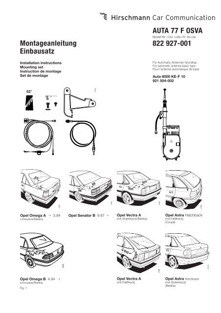
<strong>Montageanleitung</strong><br />
<strong>Einbausatz</strong><br />
Installation instructions<br />
Mounting set<br />
Instruction de montage<br />
Set de montage<br />
<strong>AUTA</strong> <strong>77</strong> F <strong>OSVA</strong><br />
Bestell-Nr. / Ord. code / N° de cde.<br />
<strong>822</strong> <strong>927</strong>-<strong>001</strong><br />
Für Automatic-Antennen Grundtyp<br />
For automatic antenna basic type<br />
Pour l'antenne automatique de base<br />
Auta 6000 KE-F 10<br />
921 504-002<br />
52°<br />
A170<br />
A114/6<br />
Opel Omega A → 3.94<br />
Limousine/Berlina<br />
Opel Senator B 9.87 →<br />
Opel Vectra A<br />
(mit Stufenheck/Berlina)<br />
Opel Astra Hatchback<br />
(mit Fließheck)<br />
(Coupé)<br />
150<br />
91<br />
A302<br />
Opel Omega B 4.94 →<br />
Limousine/Berlina<br />
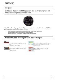
Fig. 1<br />
Opel Vectra A<br />
(mit Fließheck)<br />
Opel Astra Notchback<br />
(mit Stufenheck)<br />
(Berlina)
495 750-330
D<br />
Verkleidungen und Rücksitzbank wieder einbauen.<br />
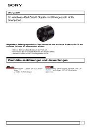
Fig. 11<br />
Omega B<br />
Ø 5,5 mm<br />
Einbauanleitung<br />
Der Einbau erfolgt bei den Opel-Modellen in den<br />
hinteren linken Kotflügel.<br />
Batterie abklemmen.<br />
Im Kofferraum die linksseitige Auskleidung<br />
entfernen. Für Kabelverlegung hintere Sitzbank<br />
ausbauen, und die linke Seitenverkleidung<br />
vorn entfernen.<br />
1. Opel Astra Fließheck und Stufenheck<br />
Das Montageteil für die Antenne ist serienmäßig<br />
vorhanden.<br />
Verschlußstopfen entfernen (Fig. 2).<br />
Antennenhalter im Antennengehäuse einrasten<br />
(Fig. 5).<br />
Beim Astra Fließheck linke Rückleuchte ausbauen.<br />
Die Antenne durch den freigelegten<br />
Rückleuchtenausschnitt einführen (Fig. 6).<br />
Vom Kofferraum aus HF-Antennenkabel an<br />
Antenne schrauben. Motorleitung mit passendem<br />
Stecker in Antenne einstecken.<br />
Antenne von unten in Montageteil einrasten,<br />
Kugel (B) vorher leicht fetten (Fig. 3).<br />
2. Opel Omega, Senator B, Vectra A<br />
Einbaustelle festlegen und Loch Ø 34 mm<br />
maßhaltig bohren (Fig. 1). Bohrung allseitig entgraten<br />
und gegen Korrosion schützen.<br />
Montageteil in leicht gefettetes Karosserieloch<br />
von oben einsetzen (Fig. 8).<br />
Antennenhalter in Antennengehäuse einrasten<br />
(Fig. 10).<br />
HF-Antennenkabel an Antenne schrauben.<br />
Motorleitung mit passendem Stecker in<br />
Antennengehäuse einstecken.<br />
Die Antenne von unten in Montageteil einrasten.<br />
Kugel (B) vorher leicht fetten (Fig. 9).<br />
Pflegehinweise<br />
Reinigen Sie bitte das Teleskop möglichst oft<br />
von anhaftendem Staub und Schmutz. Verwenden<br />
Sie nur ganz wenig von unserem Spezialfett<br />
in Tuben <strong>AUTA</strong> 235 oder benutzen Sie<br />
unser Autoantennen-Pflegetüchlein<br />
<strong>AUTA</strong> 135, das gleichzeitig reinigt und fettet.<br />
Bitte die beigefügte Gebrauchs- und Pflegeanleitung<br />
mit Garantiekarte und den beiden<br />
Autoantennen-Pflegetüchlein<br />
(<strong>AUTA</strong> 135) dem Kunden aushändigen.<br />
Ersatz-Teleskop: Bestell-Nr. 820 902-105<br />
Technische Änderungen vorbehalten.<br />
Dieses Produkt ist nach seiner Verwendung entsprechend<br />
den aktuellen Entsorgungsvorschriften<br />
Ihres Landkreises / Landes / Staates als Elektronikschrott<br />
einer geordneten Entsorgung zuzuführen.<br />
Die beschriebenen Leistungsmerkmale sind nur<br />
dann verbindlich, wenn sie bei Vertragsabschluss<br />
ausdrücklich vereinbart wurden. Diese Druckschrift<br />
wurde von Hirschmann Car Communication GmbH<br />
auf Übereinstimmung mit den beschriebenen<br />
Antennen und Antennenzubehör (Kabel, Stecker<br />
etc.) geprüft. Dennoch können Abweichungen<br />
hinsichtlich der Richtigkeit oder Genauigkeit<br />
nicht ausgeschlossen werden, sodass Hirschmann<br />
für die vollständige Übereinstimmung<br />
keine Gewähr übernimmt. Hirschmann behält<br />
sich das Recht vor, den Inhalt dieser Druckschrift<br />
ohne Ankündigung zu ändern.<br />
3. Opel Astra, Omega, Senator B, Vectra A<br />
Antennenhalter an vorhandenem Langloch am<br />
Karosseriesteg anschrauben (Fig. 5 und 10).<br />
Beim Omega B muß das Loch für den Halter<br />
nachträglich gebohrt werden (Fig. 11).<br />
HF-Kabel und die Motorleitungen parallel zu<br />
dem vorhandenen Leitungssatz unter der<br />
Rücksitzbank, von dort unter der linken Einstiegsleiste<br />
zum Autoradio verlegen und einstecken.<br />
Elektrischer Anschluß<br />
Schwarze Ader (mit Kabelschuh) im Kofferraum<br />
an vorhandener Masse-Schraube anschließen.<br />
Weiße Ader (mit Flachsteckhülse) an den<br />
Motorantennen-Steuerkontakt vom Autoradio<br />
anschließen.<br />
Rote Ader (mit Kabelsicherung) dem vorhandenen<br />
Leitungssatz nach zum Sicherungsträger<br />
verlegen. Die Formensteckhülse auf freien<br />
Stecker (Kontakt 30 Bat.+) einstecken. Bei vollständiger<br />
Belegung den Einschneidverbinder<br />
verwenden.<br />
Das Masseband an vorhandem Loch an der<br />
Verstrebung festschrauben, Anlagefläche vorher<br />
blank schaben und mit Kontaktschutzfett einstreichen<br />
(Fig. 3 und 9).<br />
Batterie anklemmen.<br />
Antenne durch Einschalten des Autoradios<br />
ausfahren. Die Neigung des Teleskops kontrollieren,<br />
die Stellung der Antenne evtl. korrigieren<br />
(ggf. Montageteil etwas drehen) und<br />
danach sämtliche Schrauben fest anziehen.<br />
GB<br />
Installation instructions<br />
Installation left-hand in the rear wing of<br />
Opel models.<br />
Disconnect the battery.<br />
Remove the left-hand panel in the luggage<br />
compartment. In order to run the cable, remove<br />
the rear seat bench and the left side panel at<br />
the front of the car.<br />
1. Opel Astra, hatchback and notchback<br />
The mounting part is provided as standard.<br />
Remove the cover plug (fig. 2).<br />
Insert the antenna support in the housing so<br />
that is locks into position (fig. 5).<br />
Remove the rear light on the Astra hatchback.<br />
Insert the antenna through the receptacle for<br />
the light (fig. 6).<br />
Connect the HF antenna cable to the antenna<br />
from the luggage compartment and insert the<br />
motor lead in the antenna using the appropriate<br />
connector.<br />
Attach the antenna to the mounting part from<br />
below so that it locks into place. Grease the<br />
ball (B) slightly beforehand (fig. 3).<br />
2. Opel Omega, Senator B, Vectra A<br />
Determine the mounting location and drill a<br />
hole with a diameter of 34 mm in accordance<br />
3
with the specified dimensions (fig. 1). Deburr the<br />
hole on all sides and apply anticorrosion protection.<br />
Grease the hole slightly and insert the mounting<br />
part from above (fig. 8).<br />
Insert the antenna support in the housing so<br />
that it locks into place (fig. 10).<br />
Attach the HF cable to the antenna. Insert the<br />
motor lead in the antenna housing using a<br />
suitable connector.<br />
Insert the antenna in the mounting part from<br />
below so that it locks into place. Grease the<br />
ball (B) slightly beforehand (fig. 9).<br />
3. Opel Astra, Omega, Senator B, Vectra A<br />
Attach the antenna support at the longitudinal<br />
hole on the body stay (fig. 5 and 10).<br />
For the Omega B it is necessary to drill the hole<br />
in the body stay for fastening the antenna support<br />
(fig. 11).<br />
Run the HF cable and motor leads (parallel to<br />
the existing leads) under the rear seat bench<br />
and from there under the left sill panel to the<br />
car radio and connect them accordingly.<br />
Electrical connection<br />
Connect the black wire (with electric terminal)<br />
to the earth screw in the luggage compartment.<br />
Connect the white wire (with blade receptacle)<br />
to the antenna-control contact for the car radio.<br />
Run the red wire (with electric terminal) to the<br />
fuse carrier parallel to the existing leads.<br />
Connect the receptacle to the free connector<br />
(contact 30 bat.+). Use the cut-in connection if<br />
none of the connectors is free.<br />
Connect the earth strap tightly to the bracing<br />
at the hole provided, scrape the mounting<br />
surface so that it is smooth and apply a layer<br />
of contact-protection grease (figs. 3 and 9).<br />
Reconnect the battery.<br />
Raise the antenna by switching on the radio.<br />
Check the angle of the telescope and correct<br />
the position of the antenna slightly if necessary<br />
(rotate the mounting part if necessary)<br />
and the tighten all screws securely.<br />
Replace the trim panels and rear seat bench.<br />
Maintenance<br />
Please clean the telescope as often as possible<br />
of adhering dust and dirt. Use only a little of<br />
our special grease <strong>AUTA</strong> 235 supplied in tubes<br />
or our car antenna tissue <strong>AUTA</strong> 135 for both<br />
cleaning and greasing.<br />
Please hand over to the customer the enclosed<br />
instructions for use and maintenance<br />
with guarantee certificate as well<br />
as the two car antenna tissues (<strong>AUTA</strong> 135).<br />
Replacement telescope:<br />
Ord. code 820 902-105<br />
Right of modification reserved.<br />
Hirschmann Car Communication GmbH<br />
Stuttgarter Strasse 45 - 51<br />
D-72654 Neckartenzlingen<br />
Tel (07127) 14-1873<br />
Fax (07127) 14-1428<br />
After its use, this product has to be processed<br />
as electronique scrap to a proper disposal<br />
according to the prevailing waste disposal regulations<br />
of your community / district / country /<br />
state.<br />
The performance features described here are binding<br />
only if they have been expressly guaranteed<br />
in the contract. This publication has been created<br />
by Hirschmann Car Communication GmbH<br />
according to the best of our knowledge.<br />
Hirschmann reserves the right to change the<br />
contents of this manual without prior notice.<br />
Hirschmann can give no guarantee in respect of<br />
the correctness or accuracy of the details in this<br />
publication.<br />
F<br />
Instruction de montage<br />
Le montage s'effectue, sur les modèles Opel,<br />
dans l'aile arrière gauche.<br />
Débrancher la batterie.<br />
Enlever la garniture du côté gauche dans le<br />
coffre. En vue de la pose des câbles, déposer<br />
la banquette arrière et enlever la garniture<br />
latérale gauche à l'avant.<br />
1. Opel Astra, coupé et berline<br />
La pièce de montage pour l'antenne existe en<br />
série.<br />
Enlever le bouchon (fig. 2).<br />
Enclencher le support d'antenne dans le<br />
boîtier d'antenne (fig. 5).<br />
Sur l'Astra coupé, déposer feu de recul gauche.<br />
Introduire l'antenne par la découpe dégagée<br />
du feu de recul (fig. 6).<br />
Depuis le coffre, visser le câble d'antenne H.F.<br />
sur l'antenne, enficher le câble du moteur<br />
avec le connecteur approprié dans l'antenne.<br />
Enclencher l'antenne par le bas dans la pièce<br />
de montage, graisser auparavant légèrement<br />
la bille (B) (fig. 3).<br />
2. Opel Omega, Senator B, Vectra A<br />
Déterminer l'emplacement de montage et<br />
percer un trou de 34 mm de diamètre aux<br />
dimensions exactes (fig. 1). Ebavurer le trou<br />
de tous les côtes et le protéger contre la corrosion.<br />
Introduire la pièce de montage dans le trou de<br />
la carrosserie légèrement graissé par le haut<br />
(fig. 8).<br />
Enclencher le support d'antenne dans le<br />
boîtier d'antenne (fig. 10).<br />
Visser le câble d'antenne H.F. sur l'antenne.<br />
Enficher le câble du moteur avec le connecteur<br />
approprié dans le boîtier de l'antenne.<br />
Enclencher l'antenne par le bas dans la pièce<br />
de montage. Graisser auparavant légèrement<br />
la bille (B) (fig. 9).<br />
3. Opel Astra, Omega, Senator B, Vectra A<br />
Visser le support d'antenne sur le trou oblong<br />
sur le renfort de la carrosserie (fig. 5 et 10).<br />
En cas de l'Omega B, pour la fixation du support<br />
il est nécessaire de percer le trou dans le<br />
renfort de la carrosserie (fig. 11).<br />
Poser le câble H.F. et les câbles du moteur<br />
parallèlement au faisceau de câbles existant<br />
sur la banquette arrière, puis de là sous la<br />
baguette d'accès gauche jusqu'à l'autoradio,<br />
et l'enficher.<br />
Branchement électrique<br />
Raccorder le conducteur noir (à cosse) à la vis<br />
de mise à la masse existant dans le coffre.<br />
Raccorder le conducteur blanc (à fiche femelle<br />
plate) au contact de commande de l'antenne<br />
électrique de l'autoradio.<br />
Poser le conducteur rouge (à fusible pour<br />
câbles) le long du faisceau de câbles existant<br />
jusqu'au porte-fusible. Enficher la fiche femelle<br />
mouleé sur le connecteur libre (contact 30,<br />
+batt.). Si tous les contacts sont affectés, utiliser<br />
le raccord par déplacement d'isolation.<br />
Visser la tresse de masse sur le trou existant<br />
sur le renfort, gratter auparavant la surface<br />
d'appui à nu et l'enduire de graisse de protection<br />
pour contacts (fig. 3 et 9).<br />
Brancher la batterie.<br />
Faire sortir l'antenne en mettant l'autoradio en<br />
marche. contrôler l'inclinaison du télescope,<br />
corriger éventuellement légèrement la position<br />
de l'antenne (tourner un peu la pièce d montage<br />
le cas échéant) puis serrer toutes les vis.<br />
Reposer les garnitures et la banquette<br />
l'arrière.<br />
Conseils d'entretien<br />
Veuillez nettoyer le télescope le plus souvent<br />
possible de la poussière adhérente et de la<br />
saleté. N'utilisez que très peu de notre graisse<br />
spéciale en tube <strong>AUTA</strong> 235 ou bien notre<br />
essuie-antenne <strong>AUTA</strong> 135 qui nettoie et graisse<br />
en même temps.<br />
Veuillez transmettre au client le mode<br />
d'emploi et d'entretien ci-jointe avec le bulletin<br />
de garantie et les deux essuies-antenne<br />
(<strong>AUTA</strong> 135).<br />
Télescope de rechange:<br />
N° de cde. 820 902-105<br />
Sous réserve de modifications techniques.<br />
Ce produit doit être éliminé en tant que déchet<br />
électronique conformément au réglement actuel<br />
sur l'élimination des déchets de votre département<br />
/ région / pays.<br />
La société Hirschmann Car Communication GmbH<br />
ne se porte garante de la véracité des informations<br />
techniques que si elles ont été spécifiées de<br />
manière expresse à la signature du contrat.<br />
Le contenu de ce document a été minutieusement<br />
contrôlé afin de s’assurer qu’il corresponde<br />
bien aux antennes et accessoires (câbles,<br />
connecteurs) décrits. Toutefois, Hirschmann ne<br />
peut en aucun cas être tenu responsable de<br />
l’exactitude de ces informations. Hirschmann se<br />
réserve le droit de modifier sans préavis le contenu<br />
de ce document.<br />
024 968-<strong>001</strong>-06-0305-N<br />
Printed in Europe . Imprimé en Europe