Schéma de liaison à la terre TT - Intersections - Schneider Electric
Schéma de liaison à la terre TT - Intersections - Schneider Electric
Schéma de liaison à la terre TT - Intersections - Schneider Electric

Create successful ePaper yourself
Turn your PDF publications into a flip-book with our unique Google optimized e-Paper software.
K242<br />
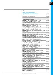
Etu<strong>de</strong> d’une instal<strong>la</strong>tion<br />
Protection <strong>de</strong>s personnes<br />
et <strong>de</strong>s biens<br />
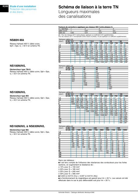
Schéma <strong>de</strong> <strong>liaison</strong> à <strong>la</strong> <strong>terre</strong> TN<br />
Longueurs maximales<br />
<strong>de</strong>s canalisations<br />
NS80H-MA<br />
Réseau triphasé 400 V, câble cuivre,<br />
Sph = Spe, U L = 50 V en schéma TN.<br />
NS100N/H/L<br />
Déclencheur type TM-G<br />
Réseau triphasé 400 V, câble cuivre, Sph = Spe,<br />
U L = 50 V en schéma TN.<br />
NS100N/H/L<br />
Déclencheur type MA<br />
Réseau triphasé 400 V, câble cuivre, Sph = Spe,<br />
U L = 50 V en schéma TN.<br />
NS160N/H/L à NS630N/H/L<br />
Déclencheur type MA<br />
Réseau triphasé 400 V, câble cuivre, Sph = Spe,<br />
U L = 50 V en schéma TN.<br />
Facteurs <strong>de</strong> correction à appliquer aux réseaux 400 V entre phases (1)<br />
m = Sph/Spe 1 2 3 4<br />
câble cuivre 1 0,67 0,5 0,4<br />
câble alu 0,62 0,41 0,31 0,25<br />
(1) : Pour les réseaux 237 V entre phases, appliquer un coefficient 0,57 supplémentaire.<br />
Pour les réseaux 237 V monophasés (entre neutre et phase), ne pas appliquer ce cœfficient supplémentaire.<br />
Sphases calibre (A)<br />
(mm 2 ) In (A) 2,5 6,3 12,5 25 50 80<br />
Im (A) 15 35 35 88 75 175 150 350 300 700 480 1120<br />
1,5 333 143 143 57 67 29 33 14 17 7 10 4<br />
2,5 556 238 238 95 111 48 56 24 28 12 17 7<br />
4 889 381 381 152 178 76 89 38 44 19 28 12<br />
6 1333 571 571 227 267 114 133 57 67 29 42 18<br />
10 952 952 379 444 190 222 95 111 48 69 30<br />
16 1524 1524 606 711 300 356 152 178 76 111 48<br />
25 947 1111 476 556 238 278 119 174 74<br />
35 1326 1556 667 778 333 389 167 243 104<br />
50 952 1111 476 556 238 347 149<br />
70 1333 1556 667 778 333 486 208<br />
Sphases calibre (A)<br />
(mm 2 ) In (A) 16 25 40 63<br />
Im (A) 63 80 80 125<br />
1,5 79 63 63 40<br />
2,5 132 104 104 67<br />
4 212 167 167 107<br />
6 317 250 250 160<br />
10 529 417 417 267<br />
16 847 667 667 427<br />
25 1042 1042 667<br />
35 1458 1458 933<br />
50 2083 1333<br />
70 1867<br />
Sphases calibre (A)<br />
(mm 2 ) In (A) 2,5 6,3 12,5 25 50 100<br />
Im (A) 15 35 35 88 75 175 150 350 300 700 600 1400<br />
1,5 333 143 143 57 67 29 33 14 17 7 8 4<br />
2,5 556 238 238 95 111 48 56 24 28 12 14 6<br />
4 889 381 381 152 178 76 89 38 44 19 22 10<br />
6 1333 571 571 227 267 114 133 57 67 29 33 14<br />
10 952 952 379 444 190 222 95 111 48 56 24<br />
16 1524 1524 606 711 300 356 152 178 76 89 38<br />
25 947 1111 476 556 238 278 119 138 60<br />
35 1326 1556 667 778 333 389 167 194 85<br />
50 952 1111 476 556 238 278 119<br />
70 1333 1556 667 778 333 389 167<br />
95 528 226<br />
120 667 286<br />
150 724 310<br />
185 856 367<br />
Sphases calibre (A)<br />
(mm 2 ) In (A) 100 150 220 320 500<br />
Im (A) 600 1400 1200 1950 1760 2860 2560 4160 4000 6500<br />
1,5 8 4 4 3 3 2 2 1 1 1<br />
2,5 14 6 7 4 5 3 3 2 2 1<br />
4 22 10 11 7 8 5 5 3 3 2<br />
6 33 14 17 10 11 7 8 5 5 3<br />
10 56 24 28 17 19 12 13 8 8 5<br />
16 89 38 44 27 30 19 20 13 13 8<br />
25 139 60 68 43 47 29 33 20 21 13<br />
35 194 85 97 60 66 41 46 28 29 18<br />
50 278 119 139 85 95 58 65 40 42 26<br />
70 120 133 82 91 56 58 36<br />
95 180 111 124 76 79 49<br />
120 156 96 100 62<br />
150 108 67<br />
185 128 79<br />
Dans ces tableaux :<br />
b il est tenu compte <strong>de</strong> l'influence <strong>de</strong>s réactances <strong>de</strong>s conducteurs pour les fortes<br />
sections, en augmentant <strong>la</strong> résistance <strong>de</strong> :<br />
v 15% pour S = 150 mm 2<br />
v 20% pour S = 185 mm 2<br />
v 25% pour S = 240 mm 2<br />
v 30% pour S = 300 mm 2<br />
b 0,023 Ω mm 2 /m (Cu) = 0,037 Ω mm 2 /m (Alu)<br />
b le fonctionnement du magnétique est garanti pour Im ± 20 %. Les calculs ont été<br />
effectués dans le cas le plus défavorable soit pour Im + 20 %.<br />
Schnei<strong>de</strong>r <strong>Electric</strong> - Catalogue distribution électrique 2002