Schéma de liaison à la terre TT - Intersections - Schneider Electric
Schéma de liaison à la terre TT - Intersections - Schneider Electric
Schéma de liaison à la terre TT - Intersections - Schneider Electric

You also want an ePaper? Increase the reach of your titles
YUMPU automatically turns print PDFs into web optimized ePapers that Google loves.
K244<br />
Etu<strong>de</strong> d’une instal<strong>la</strong>tion<br />
Protection <strong>de</strong>s personnes<br />
et <strong>de</strong>s biens<br />
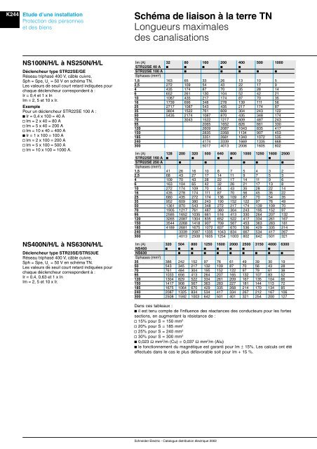
Schéma <strong>de</strong> <strong>liaison</strong> à <strong>la</strong> <strong>terre</strong> TN<br />
Longueurs maximales<br />
<strong>de</strong>s canalisations<br />
NS100N/H/L à NS250N/H/L<br />
Déclencheur type STR22SE/GE<br />
Réseau triphasé 400 V, câble cuivre,<br />
Sph = Spe, U L<br />
= 50 V en schéma TN.<br />
Les valeurs <strong>de</strong> seuil court retard indiquées pour<br />
chaque déclencheur correspon<strong>de</strong>nt à :<br />
Ir = 0,4 et 1 x In<br />
Im = 2, 5 et 10 x Ir.<br />
Exemple<br />
Pour un déclencheur STR22SE 100 A :<br />
b Ir = 0,4 x 100 = 40 A<br />
v Im = 2 x 40 = 80 A<br />
v Im = 5 x 40 = 200 A<br />
v Im = 10 x 40 = 400 A<br />
b Ir = 1 x 100 = 100 A<br />
v Im = 2 x 100 = 200 A<br />
v Im = 5 x 100 = 500 A<br />
v Im = 10 x 100 = 1000 A.<br />
NS400N/H/L à NS630N/H/L<br />
Déclencheur type STR23SE/STR53UE<br />
Réseau triphasé 400 V, câble cuivre,<br />
Sph = Spe, U L<br />
= 50 V en schéma TN.<br />
Les valeurs <strong>de</strong> seuil court retard indiquées pour<br />
chaque déclencheur correspon<strong>de</strong>nt à :<br />
Ir = 0,4, 0,63 et 1 x In<br />
Im = 2, 5 et 10 x Ir.<br />
Im (A) 32 80 160 200 400 500 1000<br />
STR22SE 40 A b b b b b<br />
STR22SE 100 A b b b b b<br />
Sphases (mm 2 )<br />
1,5 163 65 33 26 13 10 5<br />
2,5 272 109 54 43 22 17 9<br />
4 435 174 87 70 35 28 14<br />
6 652 261 130 104 52 42 21<br />
10 1087 435 217 174 87 70 35<br />
16 1739 696 348 278 139 111 56<br />
25 2717 1087 543 435 217 174 87<br />
35 3804 1522 761 609 304 243 122<br />
50 5435 2174 1087 870 435 348 174<br />
70 3043 1522 1217 609 487 243<br />
95 2065 1652 826 661 330<br />
120 2609 2087 1043 835 417<br />
150 2835 2268 1134 907 453<br />
185 3351 2681 1340 1072 535<br />
240 4174 3339 1669 1335 668<br />
300 5017 4013 2006 1605 802<br />
Im (A) 128 200 320 500 640 800 1000 1250 1600 2500<br />
STR22SE 160 A b b b b b<br />
STR22SE 250 A b b b b b<br />
Sphases (mm 2 )<br />
1,5 41 26 16 10 8 7 5 4 3 2<br />
2,5 68 43 27 17 14 11 9 7 5 3<br />
4 109 70 43 28 22 17 14 11 9 6<br />
6 163 104 65 42 32 26 21 17 13 8<br />
10 272 174 109 70 54 43 35 28 22 14<br />
16 435 278 174 111 87 70 56 45 35 22<br />
25 680 435 272 174 136 109 87 70 54 35<br />
35 952 609 380 243 190 152 122 97 76 49<br />
50 1361 870 543 348 272 217 174 139 109 70<br />
70 1905 1217 761 487 380 304 243 195 152 97<br />
95 2585 1652 1035 661 516 413 330 264 207 132<br />
120 3265 2087 1304 835 652 522 417 334 261 167<br />
150 3544 2268 1418 907 709 567 453 363 283 181<br />
185 4189 2681 1675 1072 837 670 536 429 335 214<br />
240 3339 2087 1335 1043 834 667 534 417 267<br />
300 4013 2508 1605 1254 1003 802 642 501 321<br />
Im (A) 320 504800 1250 1600 2000 2500 3150 4000 6300<br />
NS400 b b b b b b b b<br />
NS630 b b b b b b b b b<br />
Sphases (mm 2 )<br />
35 386 242 152 97 76 61 49 39 30 19<br />
50 543 345 217 132 109 87 70 56 43 28<br />
70 761 484 304 195 152 122 97 79 61 38<br />
95 1033 656 413 264 207 165 132 107 83 52<br />
120 1304 829 522 334 261 209 167 135 104 66<br />
150 1417 908 567 363 283 227 181 144 113 72<br />
185 1675 1064 670 429 335 268 214 170 134 85<br />
240 2087 1325 834 534 417 334 267 212 167 106<br />
300 2508 1592 1003 642 501 401 321 254 200 127<br />
Dans ces tableaux :<br />
b il est tenu compte <strong>de</strong> l'influence <strong>de</strong>s réactances <strong>de</strong>s conducteurs pour les fortes<br />
sections, en augmentant <strong>la</strong> résistance <strong>de</strong> :<br />
v 15% pour S = 150 mm 2<br />
v 20% pour S = 185 mm 2<br />
v 25% pour S = 240 mm 2<br />
v 30% pour S = 300 mm 2<br />
b 0,023 Ω mm 2 /m (Cu) = 0,037 Ω mm 2 /m (Alu)<br />
b le fonctionnement du magnétique est garanti pour Im ± 15%. Les calculs ont été<br />
effectués dans le cas le plus défavorable soit pour Im + 15 %.<br />
Schnei<strong>de</strong>r <strong>Electric</strong> - Catalogue distribution électrique 2002