Viola (PDF)
Viola (PDF)
Viola (PDF)

You also want an ePaper? Increase the reach of your titles
YUMPU automatically turns print PDFs into web optimized ePapers that Google loves.
ISTRUZIONI PER L’INSTALLAZIONE, L’USO E LA MANUTENZIONE -IT<br />
INSTRUCTIONS FOR INSTALLATION, USE AND MAINTENANCE - EN<br />
ANWEISUNGEN FÜR DIE AUFSTELLUNG, DEN GEBRAUCH UND DIE WARTUNG – DE<br />
INSTRUCTIONS POUR L’INSTALLATION, L’UTILISATION ET L’ENTRETIEN - FR<br />
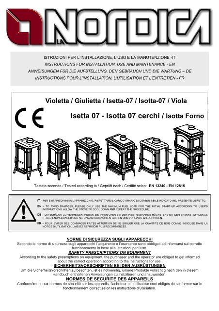
Violetta / Giulietta / Isetta-07 / Isotta-07 / <strong>Viola</strong><br />
|<br />
Isetta 07 - Isotta 07 cerchi / Isotta Forno<br />
Testata secondo / Tested according to / Geprüft nach / Certifié selon: EN 13240 - EN 12815<br />
IT – PER EVITARE DANNI ALL’APPARECCHIO, RISPETTARE IL CARICO ORARIO DI COMBUSTIBILE INDICATO NEL PRESENTE LIBRETTO.<br />
EN – TO AVOID DAMAGES, PLEASE ONLY USE THE MAXIMUM FUEL LOAD FOR THE INITIAL START-UP ACCORDING TO USER'S<br />
INSTRUCTIONS. ALLOW THE STOVE TO COOL DOWN AND REPEAT THE PROCEDURE.<br />
DE – UM SCHÄDEN ZU VERMEIDEN, HEIZEN SIE IHREN OFEN BEI DER INBETRIEBNAHME HÖCHSTENS MIT DER BRENNSTOFFMENGE<br />
IT. BEDIENUNGSANLEITUNG AN. DANACH AUSKÜHLEN LASSEN UND VORGANG WIEDERHOLEN.<br />
FR – POUR EVITER DES DOMMAGES FAITES ATTENTION DE NE BRULER QUE LA QUANTITE DE BOIS COMME INDIQUEE DANS LA<br />
NOTICE D'UTILISATION. LAISSEZ REFROIDIR PUIS RECOMMENCES.<br />
NORME DI SICUREZZA SUGLI APPARECCHI<br />
Secondo le norme di sicurezza sugli apparecchi l’acquirente e l’esercente sono obbligati ad informarsi sul corretto<br />
funzionamento in base alle istruzioni per l’uso.<br />
SAFETY PRESCRIPTIONS ON EQUIPMENT<br />
According to the safety prescriptions on equipment, the purchaser and the operator are obliged to get informed<br />
about the correct operation according to the instructions for use.<br />
SICHERHEITSVORSCHRIFTEN BEI DEN AUSRÜSTUNGEN<br />
Um die Sicherheitsvorschriften zu beachten, ist es notwendig, unsere Produkte vorsichtig nach den in diesem<br />
Handbuch enthaltenen Anweisungen zu installieren und anzuwenden.<br />
NORMES DE SECURITE DES APPAREILS<br />
Conformément aux normes de sécurité sur les appareils, l’acheteur et l’utilisateur sont obligés de s’informer sur le<br />
fonctionnement correct selon les instructions d’utilisation.
GIULIETTA – ISETTA-07 – ISOTTA-07 – ISOTTA FORNO – VIOLA – VIOLETTA<br />
DICHIARAZIONE DI CONFORMITA’ DEL COSTRUTTORE<br />
Oggetto: assenza di amianto e cadmio<br />
Si dichiara che tutti i nostri apparecchi vengono assemblati con materiali che non presentano parti di amianto o suoi<br />
derivati e che nel materiale d’apporto utilizzato per le saldature non è presente/utilizzato in nessuna forma il cadmio,<br />
come previsto dalla norma di riferimento.<br />
Oggetto: Regolamento CE n. 1935/2004<br />
Si dichiara che in tutti gli apparecchi da noi prodotti, i materiali destinati a venire a contatto con i cibi sono adatti<br />
all’uso alimentari, in conformità al Regolamento CE in oggetto.<br />
DECLARATION OF CONFORMITY OF THE MANUFACTURER<br />
Object: Absence of asbestos and cadmium<br />
We declare that the materials used for the assembly of all our appliances are without asbestos parts or asbestos<br />
derivates and that in the material used for welding, cadmium is not present, as prescribed in relevant norm.<br />
Object: CE n. 1935/2004 regulation.<br />
We declare that in all products we produce, the materials which will get in touch with food are suitable for alimentary<br />
use, according to the a.m. CE regulation.<br />
KONFORMITÄTSERKLÄRUNG DES HERSTELLERS<br />
Betreff: Fehlen von Asbest und Kadmium<br />
Wir bestätigen, dass die verwendeten Materialen oder Teilen für die Herstellung der La Nordica Geräte ohne Asbest<br />
und Derivat sind und auch das Lot für das Schweißen immer ohne Kadmium ist.<br />
Betreff: Ordnung CE n. 1935/2004. Wir erklären in alleiniger Verantwortung, dass die Materialien der Teile, die für<br />
den Kontakt mit Lebensmitteln vorgesehen sind, für die Nahrungsbenutzung geeignet sind und der Richtlinien CE n.<br />
1935/2004 erfüllen.<br />
DÉCLARATION DE CONFORMITÉ DU FABRICANT<br />
Objet: absence d'amiante et de cadmium<br />
Nous déclarons que tous nos produits sont assemblés avec des matériaux qui ne présentent pas de parties en<br />
amiante ou ses dérivés et que le matériel d'apport utilisé pour les soudures ne présente/utilise pas de cadmium, sous<br />
aucune forme, comme prévu par la norme de référence.<br />
Objet: Règlement CE n. 1935/2004. Nous déclarons que dans tous nos appareils, les matériaux destinés à entrer en<br />
contact avec les aliments sont aptes à l'usage alimentaire, conformément au Règlement CE en question<br />
2 1195300 Rev.09 – IT – EN – DE – FR
GIULIETTA – ISETTA-07 – ISOTTA-07 – ISOTTA FORNO – VIOLA – VIOLETTA<br />
ISOTTA FORNO<br />
PRIMA DELL’INSTALLAZIONE ESEGUIRE LE SEGUENTI VERIFICHE.<br />
BEFORE THE INSTALLATION PERFORM THE FOLLOWING CHECKS.<br />
VOR DER AUFSTELLUNG FOLGENDE PRÜFUNGEN AUSFÜHREN.<br />
AVANT L’INSTALLATION IL FAUT RÉALISER LES SUIVANTES VÉRIFICATIONS.<br />
NON INCLINARE LA STUFA<br />
DO NOT TILT THE STOVE<br />
DEN OFEN NICHT KIPPEN<br />
NE PAS INCLINER LE POÊLE<br />
1195300 Rev.09 – IT – EN – DE – FR 3
GIULIETTA – ISETTA-07 – ISOTTA-07 – ISOTTA FORNO – VIOLA – VIOLETTA<br />
INDICE<br />
IT<br />
1. DATI TECNICI ................................................................................................................................................... 6<br />
2. DESCRIZIONE TECNICA .................................................................................................................................. 7<br />
3. NORME PER L’INSTALLAZIONE ...................................................................................................................... 7<br />
4. SICUREZZA ANTINCENDIO ............................................................................................................................. 8<br />
4.1. PRONTO INTERVENTO ............................................................................................................................ 9<br />
5. CANNA FUMARIA ............................................................................................................................................. 9<br />
5.1. POSIZIONE DEL COMIGNOLO ................................................................................................................. 9<br />
6. COLLEGAMENTO AL CAMINO ....................................................................................................................... 11<br />
7. AFFLUSSO D’ARIA NEL LUOGO D’INSTALLAZIONE DURANTE LA COMBUSTIONE ................................... 11<br />
8. COMBUSTIBILI AMMESSI / NON AMMESSI ................................................................................................... 11<br />
9. ACCENSIONE ................................................................................................................................................. 12<br />
10. FUNZIONAMENTO NORMALE .................................................................................................................... 13<br />
11. USO DEL FORNO (dove presente) .............................................................................................................. 13<br />
12. FUNZIONAMENTO NEI PERIODI DI TRANSIZIONE ................................................................................... 14<br />
13. MANUTENZIONE E CURA .......................................................................................................................... 14<br />
13.1. PULIZIA CANNA FUMARIA .................................................................................................................. 14<br />
13.2. PULIZIA VETRO................................................................................................................................... 14<br />
13.3. PULIZIA CASSETTO CENERE ............................................................................................................ 14<br />
14. FERMO ESTIVO .......................................................................................................................................... 14<br />
15. COLLEGAMENTO ALLA CANNA FUMARIA DI UN CAMINETTO O FOCOLARE APERTO ......................... 15<br />
15. SCHEDA TECNICA – TECHNICAL DATA SHEETS – TECHNISCHE PROTOKOLLE .................................. 45<br />
INDEX<br />
EN<br />
1. TECHNICAL DATA .......................................................................................................................................... 16<br />
2. TECHNICAL DESCRIPTION ............................................................................................................................ 17<br />
3. RULES FOR INSTALLATION........................................................................................................................... 17<br />
4. FIRE SAFETY .................................................................................................................................................. 18<br />
4.1. FIRST-AID MEASURES ........................................................................................................................... 18<br />
5. FLUE ............................................................................................................................................................... 18<br />
5.1. CHIMNEY CAP ........................................................................................................................................ 19<br />
6. CONNECTION TO THE CHIMNEY .................................................................................................................. 20<br />
7. AIR ENTRANCE INTO THE INSTALLATION PLACE DURING COMBUSTION ................................................ 21<br />
8. ADMITTED/NOT ADMITTED FUEL ................................................................................................................. 21<br />
9. LIGHTING ........................................................................................................................................................ 22<br />
10. NORMAL OPERATION ................................................................................................................................ 22<br />
11. USE OF THE OVEN..................................................................................................................................... 23<br />
12. OPERATION IN TRANSITION PERIODS ..................................................................................................... 23<br />
13. MAINTENANCE AND CARE ........................................................................................................................ 23<br />
13.1. CLEANING OF THE FLUE ................................................................................................................... 23<br />
13.2. CLEANING OF THE GLASS ................................................................................................................. 24<br />
13.3. CLEANING OF THE ASH DRAWER ..................................................................................................... 24<br />
14. SUMMER STOP .......................................................................................................................................... 24<br />
15. CONNECTING A CHIMNEY OR OPEN FURNACE TO THE FLUE .............................................................. 24<br />
15. SCHEDA TECNICA – TECHNICAL DATA SHEETS – TECHNISCHE PROTOKOLLE .................................. 45<br />
4 1195300 Rev.09 – IT – EN – DE – FR
GIULIETTA – ISETTA-07 – ISOTTA-07 – ISOTTA FORNO – VIOLA – VIOLETTA<br />
INHALTSVERZEICHNIS<br />
DE<br />
1. TECHNISCHE ANGABEN................................................................................................................................ 25<br />
2. TECHNISCHE BESCHREIBUNG ..................................................................................................................... 26<br />
3. INSTALLATIONSVORSCHRIFTEN .................................................................................................................. 26<br />
4. BRANDSCHUTZ .............................................................................................................................................. 27<br />
4.1. NOTFALLMASSNAHMEN ........................................................................................................................ 28<br />
5. SCHORNSTEINROHR..................................................................................................................................... 28<br />
5.1. SCHORNSTEIN ....................................................................................................................................... 28<br />
6. KAMINANSCHLUSS ........................................................................................................................................ 30<br />
7. LUFTZUSTROM IN DEN AUFSTELLRAUM WÄHREND DER VERBRENNUNG.............................................. 30<br />
8. ZULÄSSIGE / UNZULÄSSIGE BRENNSTOFFE .............................................................................................. 31<br />
9. ANZÜNDEN ..................................................................................................................................................... 31<br />
10. NORMALBETRIEB....................................................................................................................................... 32<br />
11. BACKEN (wenn anwesend).......................................................................................................................... 33<br />
12. BETRIEB IN DER ÜBERGANGSZEIT .......................................................................................................... 33<br />
13. WARTUNG UND PFLEGE ........................................................................................................................... 33<br />
13.1. Reinigung des Schornsteins ................................................................................................................. 33<br />
13.2. Reinigung des Sichtfensters ................................................................................................................. 33<br />
13.3. Reinigung des Aschekastens ................................................................................................................ 34<br />
14. SOMMERPAUSE ......................................................................................................................................... 34<br />
15. ANSCHLUSS AN DEN RAUCHABZUG EINES OFFENEN KAMINS ............................................................ 34<br />
15. SCHEDA TECNICA – TECHNICAL DATA SHEETS – TECHNISCHE PROTOKOLLE .................................. 45<br />
TABLE DES MATIERES<br />
FR<br />
1. DONNÉES TECHNIQUES ............................................................................................................................... 35<br />
2. DESCRIPTION TECHNIQUE ........................................................................................................................... 36<br />
3. NORMES POUR L’INSTALLATION ................................................................................................................. 36<br />
4. SÉCURITÉ ANTI-INCENDIE ............................................................................................................................ 37<br />
4.1. INTERVENTION D'URGENCE ................................................................................................................. 38<br />
5. CONDUIT DE CHEMINEE ............................................................................................................................... 38<br />
5.1. POSITION DU TERMINAL DE CHEMINEE .............................................................................................. 38<br />
6. RACCORDEMENT A LA CHEMINEE............................................................................................................... 40<br />
7. ARRIVÉE D'AIR DANS LE LIEU D'INSTALLATION PENDANT LA COMBUSTION .......................................... 40<br />
8. COMBUSTIBLES ADMIS / NON ADMIS .......................................................................................................... 41<br />
9. ALLUMAGE ..................................................................................................................................................... 41<br />
10. FONCTIONNEMENT NORMAL .................................................................................................................... 42<br />
11. UTILISATION DU FOUR (où présent) .......................................................................................................... 43<br />
12. FONCTIONNEMENT AU COURS DES PÉRIODES DE TRANSITION ......................................................... 43<br />
13. MAINTENANCE ET ENTRETIEN ................................................................................................................. 43<br />
13.1. NETTOYAGE DU TUYAU D'ÉVACUATION DE LA FUMÉE .................................................................. 43<br />
13.2. NETTOYAGE DE LA VITRE ................................................................................................................. 43<br />
13.3. NETTOYAGE DU TIROIR DES CENDRES .......................................................................................... 44<br />
14. REPOS D'ETE ............................................................................................................................................. 44<br />
15. RACCORDEMENT OU D'UN FOYER OUVERT ........................................................................................... 44<br />
15. SCHEDA TECNICA – TECHNICAL DATA SHEETS – TECHNISCHE PROTOKOLLE .................................. 45<br />
1195300 Rev.09 – IT – EN – DE – FR 5
GIULIETTA – ISETTA-07 – ISOTTA-07 – ISOTTA FORNO – VIOLA – VIOLETTA<br />
1. DATI TECNICI<br />
Definizione: Stufa-camino secondo EN 13240 - EN 12815<br />
VIOLA VIOLETTA GIULIETTA<br />
ISOTTA<br />
FORNO<br />
ISETTA 07 ISOTTA 07<br />
ISETTA 07<br />
con cerchi<br />
ISOTTA 07<br />
con cerchi<br />
EN 13240 EN 13240 EN 13240 EN 12815 EN 13240 EN 13240<br />
Sistema costruttivo 1* 1* 1* 1* 1* 1*<br />
Potenza nominale in kW 7 6 6 11,5 7 9<br />
Rendimento in % 78,1 78,3 78,3 83,1 78,1 83<br />
Diametro tubo in mm 150 120 120 150 150 150<br />
Quantità max combustibile –<br />
legna in kg/h<br />
Depressione a rendimento<br />
calorifico nominale in mmH 2O<br />
CO misurato al 13% di ossigeno<br />
in %<br />
Emissione gas di scarico in g/s –<br />
legna<br />
Temperatura gas di scarico nel<br />
mezzo in C° - legna<br />
Dimensioni apertura focolare in<br />
mm (L x P)<br />
Dimensioni corpo focolare /<br />
testata focolare in mm (L x H x P)<br />
Dimensioni forno<br />
in mm (L x H x P)<br />
Tipo di griglia<br />
2,1 1,8 1,8 3,2 2,1 2,5<br />
1,2 1 1,0 1,2 1,2 1,2<br />
0,09 0,11 0,11 0,10 0,09 0,09<br />
6,1 7 7 10,3 6,1 12,31<br />
313 255 253 207 314 190<br />
380 X 245 235 x 280 235x295 519 x 305 380x288 519x371<br />
480x300x220 350x290x225 350x290x250 597x360x290<br />
467x300x293<br />
467x380x293<br />
597x360x350<br />
597x422x350<br />
/ / / 443x290x305 / /<br />
Griglia piana, girevole dall’esterno<br />
Altezza stufa in mm 706 706 706 1244<br />
706 775<br />
760 830<br />
Larghezza stufa in mm 640 495 487 795 660 790<br />
Profondità stufa (con maniglie) in<br />
mm<br />
465 440 430 530<br />
450 520<br />
590 660<br />
Peso in Kg 154 117 105 296<br />
150 190<br />
165 210<br />
Distanze di sicurezza<br />
antincendio<br />
Capitolo 4<br />
Accessorio: guanto<br />
* la porta del focolare è a chiusura automatica.<br />
Il volume di riscaldamento delle stufe secondo EN 13240 - EN 12815, per edifici il cui isolamento termico non<br />
corrisponde alle disposizioni sulla protezione del calore, è:<br />
GIULIETTA ISETTA-07 ISOTTA-07 Isotta<br />
VIOLETTA VIOLA FORNO<br />
(30 Kcal/h x m 3 ) - tipo di costruzione favorevole: 172 m³ 200 m³ 258 m³ 330 m³<br />
(40 Kcal/h x m 3 ) - tipo di costruzione meno favorevole: 129 m³ 150 m³ 193 m³ 248 m³<br />
(50 Kcal/h x m 3 ) - tipo di costruzione sfavorevole: 103 m³ 120 m³ 155 m³ 198 m³<br />
Con un isolamento termico adeguato alle disposizioni sulla protezione del calore il volume di riscaldamento è<br />
maggiore. Con un riscaldamento temporaneo, in caso di interruzioni superiori a 8h, la capacità di riscaldamento<br />
diminuisce del 25% circa.<br />
6 1195300 Rev.09 – IT
GIULIETTA – ISETTA-07 – ISOTTA-07 – ISOTTA FORNO – VIOLA – VIOLETTA<br />
2. DESCRIZIONE TECNICA<br />
Le stufe camino La Nordica si addicono a riscaldare spazi abitativi per alcuni periodi, o a sostenere un riscaldamento<br />
centralizzato insufficiente. Esse sono ideali per appartamenti di vacanza e case del fine settimana oppure come<br />
riscaldamento ausiliario durante tutto l’anno. Come combustibili vengono utilizzati ceppi di legna.<br />
La stufa-camino è costituita da fusioni di ghisa grezza e smaltata e da lastre in lamiera d’acciaio. Il focolare è<br />
internamente rivestito di singole lastre in ghisa ed è dotato di una griglia girevole estraibile. Il modello GIULIETTA è<br />
provvisto di una parete interna estraibile. Grazie a dei fori calibrati, praticati su quest’ultima, viene garantito un<br />
apporto di aria pre-riscaldata all’interno del focolare, ottenendo così una post-combustione che aumenta il rendimento<br />
e riduce le emissioni dei gas incombusti .<br />
Il focolare è dotato di una porta panoramica con vetro ceramico (resistente fino a 700°C). Questo cons ente<br />
un’affascinante vista delle fiamme ardenti ed impedisce ogni possibile fuoriuscita di scintille e fumo.<br />
Il riscaldamento dell’ambiente avviene:<br />
per irraggiamento: attraverso il vetro panoramico e le<br />
superfici esterne calde della stufa.<br />
La stufa-camino è dotata di registri aria primaria e<br />
secondaria, per mezzo dei quali viene regolata l’aria per la<br />
combustione.<br />
Registro d’aria PRIMARIA<br />
(termostato B Figura 2) (valvola B1 Figura 1)<br />
Con il termostato (Isetta-07, Isotta-07) o valvola (Giulietta),<br />
situati posteriormente sul lato destro della stufa, viene<br />
regolato il passaggio d’aria attraverso il cassetto cenere e<br />
la griglia in direzione del combustibile. L’aria primaria è<br />
necessaria per il processo di combustione. Il cassetto<br />
cenere deve essere svuotato regolarmente in modo che la<br />
cenere non possa ostacolare l’entrata d’aria primaria.<br />
Attraverso l’aria primaria viene anche mantenuto vivo il<br />
fuoco.<br />
Durante la combustione di legna, il registro aria primaria<br />
deve essere aperto solo un poco, altrimenti la legna arde<br />
troppo e la stufa si può surriscaldare. Per la disposizione<br />
corretta vedere tabella al paragrafo 10.<br />
Registro aria SECONDARIA<br />
(A Figura 2) (A1 Figura 1)<br />
Sopra la porta del focolare si trova il registro aria<br />
secondaria. Questa valvola deve essere aperta (quindi<br />
spostata verso destra) in particolare per la combustione di<br />
legna, in modo che il carbonio incombusto possa subire<br />
una post-combustione. Vedi paragrafo 10. Attraverso<br />
questo registro è possibile regolare l’andamento della<br />
Stufa. Lasciandolo leggermente aperto, a seconda del<br />
tiraggio del camino, è possibile mantenere il vetro pulito.<br />
Registro di accensione (C Figura 2) vedere paragrafo 9<br />
3. NORME PER L’INSTALLAZIONE<br />
La stufa è assemblata e pronta per l’allacciamento e deve<br />
essere collegata mediante un raccordo all’esistente canna<br />
fumaria della casa. Il raccordo deve essere possibilmente<br />
corto, rettilineo, orizzontale o posizionato leggermente in<br />
salita. I collegamenti devono essere a tenuta stagna.<br />
A<br />
A1<br />
Scuoti<br />
griglia<br />
GIULIETTA – VIOLETTA<br />
B1<br />
Figura 1<br />
ISETTA 07 – ISOTTA 07 – VIOLA C<br />
Isotta FORNO<br />
B<br />
Scuoti griglia<br />
Figura 2<br />
E’ obbligatorio rispettare norme nazionali ed europee, disposizioni locali o in materia di legislazione edilizia,<br />
nonché regolamentazioni antincendio. Pertanto vi consigliamo di informarvi preventivamente presso il Vs. capo<br />
spazzacamino distrettuale.<br />
Bisogna inoltre verificare il sufficiente afflusso d’aria necessario alla combustione, a tale proposito è fondamentale<br />
prestare attenzione a finestre e porte con chiusura stagna (guarnizioni di tenuta).<br />
1195300 Rev.09 – IT 7
GIULIETTA – ISETTA-07 – ISOTTA-07 – ISOTTA FORNO – VIOLA – VIOLETTA<br />
Non è consentito il collegamento di più apparecchi allo stesso camino. Il diametro dell’apertura della canna fumaria<br />
per il collegamento deve corrispondere per lo meno al diametro del tubo fumo.<br />
L’apertura dovrebbe essere dotata di una connessione a muro per la ricezione del tubo di scarico e di un rosone.<br />
Prima dell’installazione verificare se la portata della sottostruttura regge il peso del vostro apparecchio. In caso di<br />
portata insufficiente è necessario adottare opportune misure (ad es. piastra per la distribuzione del peso) per<br />
raggiungere la stessa.<br />
La NORDICA S.p.A. non è responsabile del prodotto modificato senza autorizzazione e tanto meno per l’uso<br />
di ricambi non originali.<br />
I FOCOLARI NON DEVONO ESSERE MODIFICATI !<br />
4. SICUREZZA ANTINCENDIO<br />
Nell’installazione della stufa devono essere osservate le seguenti misure di sicurezza:<br />
a) al fine di assicurare un sufficiente isolamento termico, rispettare la distanza minima di sicurezza dal retro e da<br />
entrambi i lati da elementi costruttivi ed oggetti infiammabili e sensibili al calore (mobili, rivestimenti di legno,<br />
stoffe ecc.) (Figura 3 A). Tutte le distanze minime di sicurezza sono indicate sulla targhetta tecnica del<br />
prodotto e NON si deve scendere al di sotto dei valori indicati;<br />
b) davanti alla stufa-camino non deve esserci alcun oggetto o materiale di costruzione infiammabile e sensibile al<br />
calore a meno di 100 cm di distanza; Tale distanza può essere ridotta a 40 cm qualora venga installata una<br />
protezione, retroventilata e resistente al calore, davanti all’intero componente da proteggere.<br />
c) qualora il prodotto venga installato su un pavimento di materiale infiammabile, bisogna prevedere un sottofondo<br />
ignifugo, per esempio una pedana d'acciaio (dimensioni secondo l’ordinamento regionale). Il sottofondo deve<br />
sporgere frontalmente di almeno 50 cm e lateralmente di almeno altri 30 cm oltre all’apertura della porta di carico<br />
(Figura 3 B).<br />
d) sopra al prodotto non devono essere presenti componenti infiammabili (es. mobili - pensili).<br />
30<br />
30<br />
100<br />
50<br />
A<br />
B<br />
Figura 3<br />
La stufa-camino deve funzionare esclusivamente con il cassetto cenere inserito. I residui solidi della combustione<br />
(ceneri) devono essere raccolti in un contenitore ermetico e resistente al fuoco. La stufa non deve mai essere accesa<br />
in presenza di emissioni gassose o vapori (per esempio colla per linoleum, benzina ecc.). Non depositate materiali<br />
infiammabili nelle vicinanze della stufa.<br />
Durante la combustione viene sprigionata energia termica che comporta un marcato riscaldamento delle superfici,<br />
della porta e del vetro del focolare, delle maniglie delle porte o di comando, del tubo fumi ed eventualmente della<br />
parte anteriore dell’apparecchio. Evitate il contatto con tali elementi senza un corrispondente abbigliamento protettivo<br />
o senza utensili accessori (guanti resistenti al calore, dispositivi di comando).<br />
Fate in modo che i bambini siano consapevoli di questi pericoli e teneteli lontani dal focolare durante il suo<br />
funzionamento.<br />
Quando si utilizza un combustibile errato o troppo umido si potrebbero formare dei depositi (creosoto) nella canna<br />
fumaria con possibile incendio della canna fumaria stessa.<br />
8 1195300 Rev.09 – IT
GIULIETTA – ISETTA-07 – ISOTTA-07 – ISOTTA FORNO – VIOLA – VIOLETTA<br />
4.1. PRONTO INTERVENTO<br />
Se si manifesta un incendio nel collegamento o nella canna fumaria :<br />
a) Chiudere la porta di caricamento e del cassetto cenere.<br />
b) Chiudere i registri dell’aria comburente<br />
c) Spegnere tramite l’uso di estintori ad anidride carbonica ( CO2 a polveri )<br />
d) Richiedere l’immediato intervento dei Vigili del Fuoco<br />
NON SPEGNERE IL FUOCO CON L’USO DI GETTI D’ACQUA.<br />
Quando la canna fumaria smette di bruciare, farla verificare da uno specialista per individuare eventuali crepe o punti<br />
permeabili.<br />
5. CANNA FUMARIA<br />
Requisiti fondamentali per un corretto funzionamento<br />
dell’apparecchio:<br />
• la sezione interna deve essere preferibilmente<br />
circolare;<br />
• essere termicamente isolata ed impermeabile e<br />
costruita con materiali idonei a resistere al calore, ai<br />
prodotti della combustione ed alle eventuali condense;<br />
• essere priva di strozzature ed avere andamento<br />
verticale con deviazioni non superiori a 45°;<br />
• se già usata deve essere pulita;<br />
• rispettare i dati tecnici del manuale di istruzioni;<br />
(1) (2)<br />
(3)<br />
(4)<br />
Max.<br />
A+1/2A<br />
A+1/2A<br />
A<br />
Qualora le canne fumarie fossero a sezione quadrata o<br />
rettangolare gli spigoli interni devono essere arrotondati con<br />
raggio non inferiore a 20 mm. Per la sezione rettangolare il<br />
rapporto massimo tra i lati deve essere ≤ 1,5.<br />
Una sezione troppo piccola provoca una diminuzione del<br />
tiraggio. Si consiglia un’altezza minima di 4 m.<br />
Sono vietate e pertanto pregiudicano il buon funzionamento<br />
dell’apparecchio: fibrocemento, acciaio zincato, superfici<br />
interne ruvide e porose. In Figura 4 sono riportati alcuni esempi<br />
di soluzione.<br />
La sezione minima deve essere di 4 dm 2 (per esempio<br />
20x20cm) per gli apparecchi il cui diametro di condotto è<br />
inferiore a 200mm, o 6,25dm 2 (per esempio 25x25cm) per<br />
gli apparecchi con diametro superiore a 200mm.<br />
Il tiraggio creato dalla vostra canna fumaria deve essere<br />
sufficiente ma non eccessivo.<br />
Una sezione della canna fumaria troppo importante può<br />
presentare un volume troppo grande da riscaldare e dunque<br />
provocare delle difficoltà di funzionamento dell’apparecchio; per<br />
(1) Canna fumaria in acciaio AISI 316 con doppia<br />
camera isolata con materiale resistente a<br />
400°C. Efficienza 100% ottima.<br />
(2) Canna fumaria in refrattario con doppia<br />
camera isolata e rivestimento esterno in<br />
calcestruzzo alleggerito. Efficienza 100%<br />
ottima.<br />
(3) Canna fumaria tradizionale in argilla sezione<br />
quadrata con intercapedini. Efficienza 80%<br />
ottima.<br />
(4) Evitare canne fumarie con sezione<br />
rettangolare interna il cui rapporto sia diverso<br />
dal disegno. Efficienza 40% mediocre.<br />
Figura 4<br />
evitare ciò provvedete ad intubare la stessa per tutta la sua altezza. Una sezione troppo piccola provoca una<br />
diminuzione del tiraggio.<br />
La canna fumaria deve essere adeguatamente distanziata da materiali infiammabili o combustibili mediante<br />
un opportuno isolamento o un’intercapedine d’aria.<br />
E’ vietato far transitare all’interno della stessa tubazioni di impianti o canali di adduzione d’aria. E’ proibito inoltre<br />
praticare aperture mobili o fisse, sulla stessa, per il collegamento di ulteriori apparecchi diversi.<br />
5.1. POSIZIONE DEL COMIGNOLO<br />
Il tiraggio della canna fumaria dipende anche dall’idoneità del comignolo.<br />
È pertanto indispensabile che, se costruito artigianalmente, la sezione di uscita sia più di due volte la sezione interna<br />
della canna fumaria.<br />
Dovendo sempre superare il colmo del tetto, il comignolo dovrà assicurare lo scarico anche in presenza di vento<br />
(Figura 5).<br />
Il comignolo deve rispondere ai seguenti requisiti:<br />
• avere sezione interna equivalente a quella del camino.<br />
• avere sezione utile d’uscita doppia di quella interna della canna fumaria.<br />
1195300 Rev.09 – IT 9
GIULIETTA – ISETTA-07 – ISOTTA-07 – ISOTTA FORNO – VIOLA – VIOLETTA<br />
• essere costruito in modo da impedire la penetrazione nella canna fumaria di pioggia, neve e di qualsiasi<br />
corpo estraneo.<br />
• essere facilmente ispezionabile, per eventuali operazioni di manutenzione e pulizia.<br />
(1) Comignolo industriale<br />
ad elementi prefabbricati,<br />
consente un ottimo<br />
smaltimento dei fumi.<br />
(2) Comignolo artigianale.<br />
La giusta sezione di uscita<br />
deve essere minimo 2 volte<br />
la sezione interna della<br />
canna fumaria, ideale 2,5<br />
volte.<br />
(3) Comignolo per<br />
canna fumaria in<br />
acciaio deflettore dei<br />
fumi a forma di cono.<br />
Figura 5<br />
50 cm (1) In caso di canne fumarie affiancate un comignolo dovrà<br />
sovrastare l’altro d’almeno 50 cm al fine d’evitare trasferimenti<br />
di pressione tra le canne stesse.<br />
Figura 6<br />
2 m 10 m<br />
1<br />
m<br />
(1) Il comignolo non deve avere ostacoli entro i 10 m da muri,<br />
falde ed alberi. In caso contrario innalzare lo stesso d’almeno<br />
1 m sopra l’ostacolo.<br />
Il comignolo deve oltrepassare il colmo del tetto d’almeno 1 m.<br />
Figura 7<br />
Inclinazione del tetto<br />
COMIGNOLI DISTANZE E POSIZIONAMENTO UNI 10683/98<br />
Distanza tra il colmo e il<br />
camino<br />
Altezza minima del camino (misurata dallo<br />
sbocco)<br />
α A (m) H (m)<br />
15°<br />
< 1,85 m 0,50 m oltre il colmo<br />
> 1,85 m 1,00 m dal tetto<br />
30°<br />
45°<br />
60°<br />
< 1,50 m 0,50 m oltre il colmo<br />
> 1,50 m 1,30 m dal tetto<br />
< 1,30 m 0,50 m oltre il colmo<br />
> 1,30 m 2,00 m dal tetto<br />
< 1,20 m 0,50 m oltre il colmo<br />
> 1,20 m 2,60 m dal tetto<br />
10 1195300 Rev.09 – IT
GIULIETTA – ISETTA-07 – ISOTTA-07 – ISOTTA FORNO – VIOLA – VIOLETTA<br />
> _ A<br />
>A<br />
0,5 m<br />
H min.<br />
(1)Asse colmo<br />
α<br />
(2)Tetto<br />
Figura 8<br />
6. COLLEGAMENTO AL CAMINO<br />
La stufa-camino è dotata di scarico fumi superiore e posteriore a pag. 50 è rappresentato il montaggio dei particolari.<br />
Il tubo di congiunzione per il collegamento al camino deve essere più corto possibile ed i punti d’unione dei singoli<br />
tubi devono essere ermetici. Il collegamento al camino deve essere eseguito con tubi stabili e robusti (Vi consigliamo<br />
uno spessore di 2 mm). Il tubo di scarico fumi deve essere fissato ermeticamente al camino. Il diametro interno del<br />
tubo di collegamento deve corrispondere al diametro esterno del tronchetto di scarico fumi della stufa. Ciò viene<br />
garantito dai tubi secondo DIN 1298.<br />
ATTENZIONE: qualora il collegamento attraversi particolari composti da materiali infiammabili, nel raggio di 20cm<br />
attorno al tubo tutti i materiali infiammabili devono essere sostituiti da materiali ignifughi e resistenti al calore.<br />
Per un buon funzionamento dell’apparecchio è essenziale che nel luogo d’installazione venga immessa sufficiente<br />
aria per la combustione. Ciò significa che, attraverso apposite aperture, deve poter circolare aria per la combustione<br />
anche a porte e finestre chiuse (vedi paragrafo 7).<br />
La depressione al camino dovrebbe essere di 12 Pa (=1.2 mm di colonna d’acqua). La misurazione deve essere fatta<br />
sempre ad apparecchio caldo (resa calorifica nominale). Quando la depressione supera i 17 PA (1,7 mm di colonna<br />
d’acqua) è necessario ridurre la stessa con l’installazione di un regolatore di tiraggio supplementare (valvola a<br />
farfalla) sul tubo di scarico o nel camino.<br />
7. AFFLUSSO D’ARIA NEL LUOGO D’INSTALLAZIONE DURANTE LA COMBUSTIONE<br />
Poiché le stufe ricavano la loro aria di combustione dal locale di installazione, è essenziale che nel luogo stesso<br />
venga immessa una sufficiente quantità d’aria. In caso di finestre e porte a tenuta stagna (es .case costruite con il<br />
criterio di risparmio energetico) è possibile che l’ingresso di aria fresca non venga più garantito e questo compromette<br />
il tiraggio dell’apparecchio, il vostro benessere e la vostra sicurezza. Bisogna pertanto garantire una alimentazione<br />
aggiuntiva di aria fresca mediante una presa d’aria esterna posta nelle vicinanze dell’apparecchio oppure tramite la<br />
posa di una conduttura per l’aria di combustione che porti verso l’esterno od in un vicino locale areato, ad eccezione<br />
del locale caldaia o garage (VIETATO).<br />
Il tubo di collegamento deve essere liscio con un diametro minimo di 120 mm, deve avere una lunghezza massima di<br />
4 m e presentare non più di tre curve. Qualora questo sia collegato direttamente con l’esterno deve essere dotato di<br />
un apposito frangivento.<br />
L’entrata d’aria per la combustione nel luogo d’installazione non deve essere ostruita durante il funzionamento della<br />
stufa. E’ assolutamente necessario che negli ambienti, in cui vengono fatte funzionare stufe con un tiraggio naturale<br />
del camino, venga immessa tanta aria quanta ne è necessaria per la combustione, ossia fino a 20 m 3 /h. Il naturale<br />
riciclo d’aria deve essere garantito da alcune aperture fisse sull’esterno. La grandezza delle necessarie aperture per<br />
l’aria è fissata dalle relative prescrizioni. Chiedete informazioni al Vostro spazzacamino di fiducia. Le aperture<br />
dovrebbero essere protette con delle griglie e non dovrebbero mai essere otturate.<br />
Una cappa di estrazione (aspirante) installata nella stessa stanza od in una confinante provoca depressione<br />
nell’ambiente. Questo porta alla fuoriuscita di gas combusti (fumo denso, odore); é dunque necessario assicurare un<br />
maggiore afflusso di aria fresca.<br />
La depressione di una cappa aspirante può, nella peggiore delle ipotesi, trasformare la canna fumaria della<br />
stufa in presa d’aria esterna risucchiando i fumi nell’ambiente con conseguenze gravissime per le persone.<br />
8. COMBUSTIBILI AMMESSI / NON AMMESSI<br />
I combustibili ammessi sono ceppi di legna da ardere. Si devono utilizzare esclusivamente ceppi di legna secca<br />
(contenuto d’acqua max 20%). Si dovrebbero caricare al massimo 2 o 3 ceppi di legna per volta o 4-5 pezzi di lignite.<br />
I pezzi di legna dovrebbero avere una lunghezza di ca. 30 – 40 cm ed una circonferenza di massimo 30 – 35 cm.<br />
La legna usata come combustibile deve avere un contenuto d’umidità inferiore al 20% e la si ottiene con un tempo di<br />
essiccazione di almeno un anno (legno tenero) o di due anni (legno duro) collocandola in un luogo asciutto e ventilato<br />
(per esempio sotto una tettoia). La legna umida rende l’accensione più difficile, poiché è necessaria una maggiore<br />
quantità d’energia per far evaporare l’acqua presente. Il contenuto umido ha inoltre lo svantaggio, con l’abbassarsi<br />
1195300 Rev.09 – IT 11
GIULIETTA – ISETTA-07 – ISOTTA-07 – ISOTTA FORNO – VIOLA – VIOLETTA<br />
della temperatura, di far condensare l’acqua prima nel focolare e quindi nel camino. La legna fresca contiene circa il<br />
60% di H 2 O, perciò non è adatta ad essere bruciata.<br />
Tra gli altri non possono essere bruciati: resti di carbone, ritagli, cascami di corteccia e pannelli, legna umida<br />
o trattata con vernici, materiali di plastica; in tal caso decade la garanzia sull’apparecchio.<br />
Carta e cartone devono essere utilizzati solo per l’accensione. La combustione di rifiuti è VIETATA e<br />
danneggerebbe inoltre la stufa e la canna fumaria, provocando inoltre danni alla salute ed in virtù del disturbo olfattivo<br />
a reclami da parte del vicinato.<br />
La legna non è un combustibile a lunga durata e pertanto non è possibile un riscaldamento continuo della stufa<br />
durante la notte.<br />
Specie Kg/mc KWh/Kg Umidità 20%<br />
Faggio 750 4,0<br />
Cerro 900 4,2<br />
Olmo 640 4,1<br />
Pioppo 470 4,1<br />
Larice * 660 4,4<br />
Abete rosso * 450 4,5<br />
Pino silvestre * 550 4,4<br />
* LEGNI RESINOSI POCO ADATTI PER UNA STUFA<br />
ATTENZIONE: l’uso continuo e prolungato di legna particolarmente ricca di oli aromatici (p.e. Eucalipto, Mirto, etc.)<br />
provoca il deterioramento (sfaldamento) repentino dei componenti in ghisa che compongono il prodotto.<br />
9. ACCENSIONE<br />
IMPORTANTE: alla prima accensione è inevitabile che venga prodotto un odore sgradevole (dovuto all’essiccamento<br />
dei collanti nella cordicella di guarnizione o delle vernici protettive), che sparisce dopo un breve utilizzo. Deve<br />
comunque essere assicurata una buona ventilazione dell’ambiente. Alla prima accensione Vi consigliamo di<br />
caricare una quantità ridotta di combustibile e di aumentare lentamente la resa calorifica dell’apparecchio.<br />
Per effettuare una corretta prima accensione dei prodotti trattati con vernici per alte temperature, occorre sapere<br />
quanto segue:<br />
i materiali di costruzione dei prodotti in questione non sono omogenei, infatti vengono utilizzate parti in ghisa e in<br />
acciaio.<br />
la temperatura alla quale il corpo del prodotto è sottoposto non è omogenea: da zona a zona si registrano<br />
temperature variabili dai 300°C ai 500°C;<br />
durante la sua vita, il prodotto è sottoposto a cicli alternati di accensioni e di spegnimento durante la stessa<br />
giornata e a cicli di intenso utilizzo o di assoluto riposo al variare delle stagioni;<br />
la stufa nuova, prima di potersi definire rodata, dovrà essere sottoposta a diversi cicli di avviamento per poter<br />
consentire a tutti i materiali ed alla vernice di completare le varie sollecitazioni elastiche;<br />
in particolare inizialmente si potrà notare l’emissione di odori tipici dei metalli sottoposti a grande sollecitazione<br />
termica e di vernice ancora fresca. Tale vernice, sebbene in fase di costruzione venga cotta a 250 °C per<br />
qualche ora, dovrà superare più volte e per una certa durata la temperatura di 350°C, prima di incorpo rarsi<br />
perfettamente con le superfici metalliche.<br />
Diventa quindi importante seguire questi piccoli accorgimenti in fase di accensione:<br />
1. Assicuratevi che sia garantito un forte ricambio d'aria nel luogo dove è installato l'apparecchio.<br />
2. Nelle prime accensioni, caricare non eccessivamente la camera di combustione (circa metà della quantità<br />
indicata nel manuale d'istruzioni) e tenere il prodotto acceso per almeno 6-10 ore di continuo, con i registri<br />
meno aperti di quanto indicato nel manuale d'istruzioni.<br />
3. Ripetere questa operazione per almeno 4-5 volte o più, secondo la Vostra disponibilità.<br />
4. Successivamente caricare sempre più ( seguendo comunque quanto descritto sul libretto di istruzione<br />
relativamente al massimo carico) e tenere possibilmente lunghi i periodi di accensione evitando, almeno in<br />
questa fase iniziale, cicli di accensione-spegnimento di breve durata.<br />
5. Durante le prime accessioni nessun oggetto dovrebbe essere appoggiato sulla stufa ed in particolare<br />
sulle superfici laccate. Le superfici laccate non devono essere toccate durante il riscaldamento.<br />
6. Una volta superato il "rodaggio" si potrà utilizzare il prodotto come il motore di un’auto, evitando bruschi<br />
riscaldamenti con eccessivi carichi.<br />
12 1195300 Rev.09 – IT
GIULIETTA – ISETTA-07 – ISOTTA-07 – ISOTTA FORNO – VIOLA – VIOLETTA<br />
Per accendere il fuoco consigliamo di usare piccoli listelli di legno con carta oppure altri mezzi di accensione in<br />
commercio, ESCLUSE tutte le sostanze liquide come per es. alcool, benzina, petrolio e simili.<br />
Funzionamento con legna:<br />
Aprire il registro aria secondaria (A , A1), aprire il termostato (B , B1), aprire il registro di tiraggio diretto (C),<br />
accendere il fuoco.<br />
Dopo circa 10 minuti , quando il fuoco è avviato, chiudere il termostato (B , B1) e il registro tiraggio (C) e regolare<br />
l’andatura con il registro (A , A1)<br />
Le aperture per l’aria (primaria e secondaria) devono essere aperte contemporaneamente solo un po' (si deve aprire<br />
anche l’eventuale valvola a farfalla posta sul tubo di scarico fumi). Quando la legna comincia ad ardere regolare l’aria<br />
per la combustione secondo le indicazioni del paragrafo 10.<br />
Mai sovraccaricare la stufa (confrontate la tabella tecnica – quantità max. di combustibile caricabile).<br />
Troppo combustibile e troppa aria per la combustione possono causare surriscaldamento e quindi<br />
danneggiare la stufa, in particolare si potrebbero verificare delle rotture sulla parte inferiore della facciata. La<br />
garanzia non copre i danni dovuti al surriscaldamento dell’apparecchio.<br />
10. FUNZIONAMENTO NORMALE<br />
IMPORTANTE: poiché la porta del focolare ha dimensioni notevoli, vi consigliamo di aprire la porta molto lentamente<br />
per evitare l’uscita di fumi. Per motivi di sicurezza la porta del focolare può essere aperta solo durante il<br />
caricamento di combustibile. Il focolare deve rimanere chiuso durante il funzionamento ed i periodi di nonutilizzo.<br />
Prima di aprire la porta del focolare, aprire il registro di tiraggio diretto (C), caricare il combustibile, chiudere la porta, e<br />
dopo circa 5 o 10 minuti il registro (C).<br />
Con i registri posti sulla facciata della stufa-camino viene regolata l’emissione di calore della stufa. Essi devono<br />
essere aperti secondo il bisogno calorifico. La migliore combustione (con emissioni minime) viene raggiunta quando,<br />
caricando legna, la maggior parte dell’aria per la combustione passa attraverso il registro d’aria secondaria.<br />
Non si deve mai sovraccaricare la stufa (vedi quantità max nella tabella sottostante).<br />
Troppo combustibile e troppa aria per la combustione possono causare surriscaldamento e quindi<br />
danneggiare la stufa, in particolare si potrebbero verificare delle rotture sulla parte inferiore della facciata. La<br />
garanzia non copre i danni dovuti al surriscaldamento dell’apparecchio.<br />
Bisogna pertanto usare la stufa sempre con la porta chiusa per evitare l’effetto forgia.<br />
La regolazione dei registri necessaria per l’ottenimento della resa calorifica nominale con una depressione al camino<br />
è la seguente:<br />
Carica oraria Aria Secondaria (A) Termostato (B) Aria Terziaria<br />
GIULIETTA 1.8 kg/h APERTO (A1) CHIUSO Valvola (B1) Pretarata<br />
ISETTA-07 2.1 kg/h APERTO APERTO 5 mm /<br />
ISOTTA-07 2.5 kg/h APERTO APERTO 5 mm /<br />
ISOTTA FORNO 3.2 kg/h APERTO APERTO 5 mm /<br />
VIOLA 2.1 kg/h APERTO APERTO /<br />
VIOLETTA 1.8 kg/h APERTO APERTO Pretarata<br />
Oltre che dalla regolazione dell’aria per la combustione, l’intensità della combustione e quindi la resa calorifica della<br />
Vostra stufa è influenzata dal camino. Un buon tiraggio del camino richiede una regolazione più ridotta dell’aria per la<br />
combustione, mentre uno scarso tiraggio necessita maggiormente di un’esatta regolazione dell’aria per la<br />
combustione.<br />
Per verificare la buona combustione della stufa, controllate se il fumo che esce dal camino è trasparente. Se è bianco<br />
significa che la stufa non è regolata correttamente o la legna è troppo bagnata; se invece il fumo è grigio o nero è<br />
segno che la combustione non è completa (è necessaria una maggior quantità di aria secondaria).<br />
11. USO DEL FORNO (dove presente)<br />
Dopo aver pulito la griglia, caricate del combustibile. Grazie all’apporto d’aria per la combustione la<br />
temperatura del forno può essere sensibilmente influenzata. Un sufficiente tiraggio al camino e dei canali<br />
ben puliti per il flusso dei fumi roventi attorno al forno sono fondamentali per un buon risultato di cottura.<br />
La padella forno può essere collocata su diversi piani. Torte spesse e arrosti grandi sono da inserire al<br />
livello più basso. Torte piatte e biscotti vanno al livello medio. Il livello superiore può essere utilizzato per<br />
riscaldare o rosolare.<br />
1195300 Rev.09 – IT 13
GIULIETTA – ISETTA-07 – ISOTTA-07 – ISOTTA FORNO – VIOLA – VIOLETTA<br />
12. FUNZIONAMENTO NEI PERIODI DI TRANSIZIONE<br />
Durante il periodo di transizione, ovvero quando le temperature esterne sono più elevate, in caso di improvviso<br />
aumento della temperatura si possono avere dei disturbi alla canna fumaria che fanno si che i gas combusti non<br />
vengono aspirati completamente. I gas di scarico non fuoriescono più completamente (odore intenso di gas).<br />
In tal caso scuotete più frequentemente la griglia e aumentate l’aria per la combustione. Caricate in seguito una<br />
quantità ridotta di combustibile facendo sì che questo bruci più rapidamente (con sviluppo di fiamme) e si stabilizzi<br />
così il tiraggio della canna fumaria. Controllate quindi che tutte le aperture per la pulizia e i collegamenti al camino<br />
siano ermetici. In caso di incertezza rinunciate all’utilizzo della stufa.<br />
13. MANUTENZIONE E CURA<br />
Fate controllare dal Vostro spazzacamino responsabile di zona la regolare installazione della stufa, il collegamento al<br />
camino e l’aerazione.<br />
Per la pulizia delle parti smaltate usare acqua saponata o detergenti non abrasivi o chimicamente non aggressivi.<br />
IMPORTANTE : si possono usare esclusivamente parti di ricambio espressamente autorizzate ed offerte da La<br />
Nordica. In caso di bisogno Vi preghiamo di rivolgerVi al Vs rivenditore specializzato.<br />
L’ APPARECCHIO NON PUÒ ESSERE MODIFICATO!<br />
13.1. PULIZIA CANNA FUMARIA<br />
La corretta procedura di accensione, l’utilizzo di quantità e tipi di combustibili idonei, il corretto posizionamento del<br />
registro dell’aria secondaria, il sufficiente tiraggio del camino e la presenza d’aria comburente sono indispensabili per<br />
il funzionamento ottimale dell’apparecchio. Almeno una volta l’anno è consigliabile eseguire una pulizia completa, o<br />
qualora sia necessario (problemi di malfunzionamento con scarsa resa). Questa operazione, fatta esclusivamente a<br />
stufa fredda, dovrebbe essere svolta da uno spazzacamino che contemporaneamente può effettuare un’ispezione.<br />
Durante la pulizia bisogna togliere dalla stufa il cassetto cenere ed il tubo fumi.<br />
Si può pulire il vano di raccolta fumi dal focolare e, dopo aver tolto il tubo fumi, anche dal tronchetto di scarico con<br />
l’aiuto di una spazzola e di un aspiratore.<br />
Fate attenzione che dopo la pulizia tutte le parti smontate vengano reinstallate in modo ermetico.<br />
13.2. PULIZIA VETRO<br />
Tramite uno specifico ingresso dell’aria secondaria la formazione di deposito di sporco, sul vetro della porta, viene<br />
efficacemente rallentata. Non può comunque mai essere evitata con l’utilizzo dei combustibili solidi (es. legna umida )<br />
e questo non è da considerarsi come un difetto dell’apparecchio .<br />
IMPORTANTE: la pulizia del vetro panoramico deve essere eseguita solo ed esclusivamente a stufa fredda<br />
per evitare l’esplosione. Non usare comunque panni, prodotti abrasivi o chimicamente aggressivi.<br />
ROTTURA DEI VETRI: i vetri essendo in vetroceramica resistenti fino ad uno sbalzo termico di 750°C, no n<br />
sono soggetti a shock termici. La loro rottura può essere causata solo da shock meccanici (urti o chiusura<br />
violenta della porta ecc.). Pertanto la sostituzione non è in garanzia .<br />
13.3. PULIZIA CASSETTO CENERE<br />
Tutte le stufe La NORDICA sono dotate di una griglia focolare e di un cassetto per la raccolta delle ceneri.<br />
Vi consigliamo di svuotare periodicamente il cassetto cenere e di evitarne il riempimento totale, per non surriscaldare<br />
la griglia. Inoltre Vi consigliamo di lasciare sempre 3-4 cm di cenere nel focolare.<br />
ATTENZIONE: le ceneri tolte dal focolare vanno riposte in un recipiente di materiale ignifugo dotato di un coperchio<br />
stagno.<br />
Il recipiente va posto su di un pavimento ignifugo, lontano da materiali infiammabili fino allo spegnimento e<br />
raffreddamento completo.<br />
14. FERMO ESTIVO<br />
Dopo aver effettuato la pulizia del focolare, del camino e della canna fumaria, provvedendo all’eliminazione totale<br />
della cenere ed altri eventuali residui, è opportuno chiudere tutte le porte con i relativi registri focolare. Nel caso in cui<br />
l’apparecchio venga disconnesso dal camino, è opportuno chiuderne il foro di uscita.<br />
E’ consigliabile effettuare l’operazione di pulizia della canna fumaria almeno una volta all’anno; verificando nel<br />
contempo l’effettivo stato delle guarnizioni che se non risultassero perfettamente integre - cioè non più aderenti alla<br />
stufa - non garantirebbero il buon funzionamento dell’apparecchio! Si renderebbe quindi necessaria la loro<br />
sostituzione.<br />
In caso di umidità del locale dove è posto l’apparecchio, sistemare dei sali assorbenti all’interno del focolare di<br />
quest’ultimo.<br />
14 1195300 Rev.09 – IT
GIULIETTA – ISETTA-07 – ISOTTA-07 – ISOTTA FORNO – VIOLA – VIOLETTA<br />
Proteggere le parti in ghisa interne alla stufa, se si vuole mantenere inalterato nel tempo l’aspetto estetico, con della<br />
vaselina neutra.<br />
15. COLLEGAMENTO ALLA CANNA FUMARIA DI UN CAMINETTO O FOCOLARE APERTO<br />
Il canale fumi è il tratto di tubo che collega il prodotto alla canna fumaria, nel collegamento devono essere rispettati<br />
questi semplici ma importantissimi principi:<br />
• per nessuna ragione si dovrà usare il canale fumo avente un diametro inferiore a quello del collarino di uscita<br />
di cui è dotato il prodotto;<br />
• ogni metro di percorso orizzontale del canale fumo provoca una sensibile perdita di carico che dovrà<br />
eventualmente essere compensata con un innalzamento della canna fumaria;<br />
• il tratto orizzontale non dovrà comunque mai superare i 2m (UNI 10683-2005);<br />
• ogni curva del canale fumi riduce sensibilmente il tiraggio della canna fumaria che dovrà essere<br />
eventualmente compensata innalzandola adeguatamente;<br />
• la Normativa UNI 10683-2005 – ITALIA prevede che le curve o variazioni di direzione non devono in nessun<br />
caso essere superiori a 2 compresa l’immissione in canna fumaria.<br />
Volendo usare la canna fumaria di un caminetto o focolare aperto, sarà necessario chiudere ermeticamente la cappa<br />
al di sotto del punto di imbocco del canale fumo pos.A Figura 9.<br />
Se poi la canna fumaria è troppo grande (p.e. cm 30x40 oppure 40x50) è necessario intubarla con un tubo di acciaio<br />
inox di almeno 200mm di diametro, pos.B, avendo cura di chiudere bene lo spazio rimanente fra il tubo stesso e la<br />
canna fumaria immediatamente sotto al comignolo pos. C.<br />
C - Tamponamento<br />
B<br />
A - Chiusura ermetica<br />
Sportello di<br />
ispezione<br />
Figura 9<br />
Per ulteriori informazioni Vi preghiamo cortesemente di rivolgerVi al Vostro rivenditore di fiducia.<br />
1195300 Rev.09 – IT 15
GIULIETTA – ISETTA-07 – ISOTTA-07 – ISOTTA FORNO – VIOLA – VIOLETTA<br />
1. TECHNICAL DATA<br />
Definition: Chimney stove tested according to: EN 13240 - EN 12815<br />
VIOLA VIOLETTA GIULIETTA<br />
ISOTTA<br />
FORNO<br />
ISETTA 07 ISOTTA 07<br />
ISETTA 07<br />
con cerchi<br />
ISOTTA 07<br />
con cerchi<br />
EN 13240 EN 13240 EN 13240 EN 12815 EN 13240 EN 13240<br />
Rating power in kW 7 6 6 11,5 7 9<br />
Efficiency in % 78.1 78.3 78.3 83,1 78.1 83<br />
Pipe diameter in mm 150 120 120 150 150 150<br />
Maximum quantity of fuel -<br />
wood in kg<br />
Depression by rating calorific<br />
value in mmH 2 O - wood<br />
Mean content of CO to 13%<br />
O 2 in %<br />
Emission of exhaust gases in<br />
g/s - wood<br />
Temperature of exhaust gas<br />
in C° - wood<br />
Size of hearth opening in mm<br />
(W x D)<br />
Hearth body size / hearth<br />
head in mm (W x H x D)<br />
2.1 1.8 1.8 3,2 2.1 2.5<br />
1.2 1 1,0 1,2 1.2 1,2<br />
0.09 0.11 0.11 0,10 0.09 0.09<br />
6.1 7 7 10,3 6.1 12.31<br />
313 255 253 207 314 190<br />
380 X 245 235 x 280 235x295 519 x 305 380x288 519x371<br />
480x300x220 350x290x225 350x290x250 597x360x290<br />
467x300x293<br />
467x380x293<br />
597x360x350<br />
597x422x350<br />
Oven size in mm (W x H x D) / / / 443x290x305 / /<br />
Grate type<br />
Flat grate<br />
Stove height in mm 706 706 706 1244<br />
706 775<br />
760 830<br />
Stove width in mm 640 495 487 795 660 790<br />
Stove depth<br />
(with handles) in mm<br />
465 440 430 530<br />
Weight in Kg 154 117 105 296<br />
Safety measures Chapter 4<br />
Accessory: glove<br />
*the door of the hearth closes automatically<br />
450 520<br />
590 660<br />
150 190<br />
165 210<br />
The heating volume of the stoves according to EN 13240 - EN 12815, for those buildings in which the thermal<br />
insulation does not correspond to the instructions on heat protection is:<br />
GIULIETTA ISETTA-07 ISOTTA-07 Isotta<br />
VIOLETTA VIOLA FORNO<br />
(30 Kcal/h x m 3 ) - type of favourable construction: 172 m³ 200 m³ 258 m³ 330 m³<br />
(40 Kcal/h x m 3 ) - type of less favourable construction: 129 m³ 150 m³ 193 m³ 248 m³<br />
(50 Kcal/h x m 3 ) - type of unfavourable construction: 103 m³ 120 m³ 155 m³ 198 m³<br />
With a suitable thermal insulation, corresponding to the provisions on heat protection, the heating volume is greater.<br />
In case of a temporary heating, with interruptions of more than 8 hours, the heating volume decreases of 25%<br />
16 1195300 Rev.09 – EN
GIULIETTA – ISETTA-07 – ISOTTA-07 – ISOTTA FORNO – VIOLA – VIOLETTA<br />
2. TECHNICAL DESCRIPTION<br />
The chimney stoves of La Nordica are suitable to heat living spaces for some periods or to support an insufficient<br />
centralized heating system. They are ideal for holiday apartments and weekend houses or as an auxiliary heating<br />
system during the whole year. As fuel, it is possible to use wood logs. The chimney stove is made of raw and<br />
enamelled meltings of cast iron and plates of steel metal sheet. The hearth is internally sheathed with single sheets in<br />
cast iron and inside it there is a turning and extractable grate. The model GIULIETTA is provided with an internal side<br />
of the hearth, which is extractable and pierced. Thanks to the calibrated holes of that side, a contribution of preheated<br />
air inside the hearth is guaranteed, obtaining a post-combustion, which increases the yield and reduces the<br />
exhaust gases emissions.<br />
The hearth is equipped with a panoramic door with ceramic<br />
glass (resistant up to 700 °C). This allows a wonde rful view<br />
GIULIETTA – VIOLETTA<br />
on the burning flames and avoids any possible output of<br />
sparks and smoke.<br />
A1<br />
The heating of the environment is made:<br />
by irradiation: through the panoramic glass and the<br />
external hot surfaces of the stove, the heat is radiated into<br />
the environment.<br />
The chimney stove is equipped with registers of primary<br />
and secondary air by which it is adjusted the combustion<br />
air.<br />
PRIMARY air control<br />
(thermostat B Picture 2), (valve B1 Picture 1)<br />
With the thermostat (Isetta 07, Isotta 07) or valve (Giulietta)<br />
placed on the back of the right side of the stove, it is<br />
adjusted the passage of air through the ash drawer and the<br />
grate in the fuel direction. The primary air is necessary for<br />
the combustion process. The ash drawer must be regularly<br />
emptied, so that the ash does not obstruct the primary air<br />
entry. Through the primary air the fire is also kept alive.<br />
During wood combustion, the register of primary air must<br />
be opened only for a while, because otherwise the wood<br />
burns fast and the stove may overheat. For the correct<br />
arrangement, see the table on chapter 10.<br />
Scuoti<br />
griglia<br />
B1<br />
Picture 1<br />
ISETTA 07 – ISOTTA 07 – VIOLA<br />
Isotta FORNO<br />
B<br />
SECONDARY air control<br />
(A Picture 2) (A1 Picture 1)<br />
Over the door of the hearth there is the secondary air<br />
control. Also this valve must be opened (then moved to the<br />
right), especially for wood combustion, so that un-burnt<br />
carbon does not undergo a post-combustion. See<br />
chapter10. Through this register it is possible to adjust the<br />
combustion course of the stove.<br />
Leaving it slightly open, according to the flue of the<br />
chimney, it is possible to keep the glass clean.<br />
Flat<br />
grate<br />
C<br />
Ignition control (C Picture 2) see chapter 9.<br />
A<br />
3. RULES FOR INSTALLATION<br />
Picture 2<br />
The stove, assembled and ready for the installation, must<br />
be connected with a junction to the existing flue of the house. The junction must be possibly short, straight, horizontal<br />
or positioned a little uphill. The connections must be tight. It is obligatory to respect the National and European<br />
rules, local regulations concerning building matter and also fireproofs rules. Please apply to your chimney<br />
sweeper for all information.<br />
You should verify the sufficient air entrance for the combustion in the installation place, with particular attention to<br />
windows and doors with tight closing (seal ropes). It is not allowed the connection of various appliances to the same<br />
chimney. The diameter of the opening for the connection must correspond at least to the diameter of the smokes pipe.<br />
The opening should be equipped with a wall connection for the reception of the exhaust pipe and a rose window.<br />
Before installation, verify if your floor can support the weight of the stove (for ex. distributing weight plate).<br />
LA NORDICA is not responsible in case of modification of the product and for the use of not original spare<br />
parts. THE HEARTHS MUST NOT BE MODIFIED.<br />
1195300 Rev.09 – EN 17
GIULIETTA – ISETTA-07 – ISOTTA-07 – ISOTTA FORNO – VIOLA – VIOLETTA<br />
4. FIRE SAFETY<br />
In the installation of the stove the following safety measures are to be followed:<br />
a) In order to ensure sufficient thermal insulation, respect the minimum safety distance from objects or furnishing<br />
components flammable and sensitive to heat (furniture, wood sheathings, fabrics. etc.) and from materials with<br />
flammable structure (Picture 3 A). All the minimum safety distances are shown on the product data plate<br />
and lower values must NOT be used.<br />
b) in front of the chimney stove there must not be any flammable object or building material, sensitive to heat, at less<br />
then 100 cm’s. of distance. This distance can be reduced to 40 cm’s if you will install in front of the element to<br />
protect a retro ventilated and heat resistant protection.<br />
c) if the product is installed on a non-totally refractory floor, one must foresee a fireproof background, for example a<br />
steel platform dimensions according to the local regulations. The platform must stick out 30 cm’s sideways and<br />
50 cm’s on the front side over the loading door (Picture 3 B)<br />
d) no flammable components (e.g. wall units) must be present above the product.<br />
30<br />
30<br />
100<br />
50<br />
A<br />
B<br />
Picture 3<br />
The chimney stove must operate exclusively with the ash drawer inserted. The solid residue of the combustion<br />
(ashes) must be collected in a hermetic container, resistant to fire. The stove must never be ignited when there are<br />
gas or steam emissions (e.g. glue for linoleum, gasoline, etc.). Never deposit flammable materials near the stove.<br />
During the combustion will be spread thermal energy which warms up the surfaces, the door, the fireplace glass, the<br />
handles and knobs, the smoke pipe and the front side of the stove. Please avoid the contact of these parts without<br />
gloves or the relevant tools.<br />
Warn children of the danger and keep them away during the operation of the stove.<br />
The use of a wrong or wet fuel causes the formation of creosote deposits in the flue and will fuel a chimney fire.<br />
4.1. FIRST-AID MEASURES<br />
Should any fire arise in the stack or in the flue:<br />
a) Close the feeding door and the ash drawer door;<br />
b) Close the controls of combustion air;<br />
c) Extinguish the fire using carbon dioxide fire-fighting means (CO 2 dust);<br />
d) Seek immediate intervention of FIRE BRIGADE.<br />
DO NOT EXTINGUISH FIRE USING WATER JETS.<br />
When the fire has been extinguished, let the flue check by an expert to find possible cracks and permeable points.<br />
5. FLUE<br />
Essential requirements for a correct operation of the appliance:<br />
• the internal section must be preferably circular;<br />
• be thermally insulated and water-proof and produced with materials suitable to resist to heat, combustion<br />
products and possible condensates;<br />
18 1195300 Rev.09 – EN
GIULIETTA – ISETTA-07 – ISOTTA-07 – ISOTTA FORNO – VIOLA – VIOLETTA<br />
• not be throttled and show a vertical arrangement with deviations not greater than 45°;<br />
• if already used, it must be clean;<br />
• observe the technical data of the instructions manual;<br />
Should the flues have a square or rectangular section, internal edges must be rounded with a radius not lower than 20<br />
mm. For the rectangular section, the maximum ratio between the sides must be ≤ 1.5.<br />
(1) (2)<br />
(3)<br />
(4)<br />
A+1/2A<br />
Max.<br />
A+1/2A<br />
A<br />
(1) AISI 316 steel flue with double chamber insulated with material resistant to 400°C. Efficiency<br />
100% excellent.<br />
(2) Refractory flue with insulated double chamber and external coating in lightweight concrete.<br />
Efficiency 100% excellent.<br />
(3) Traditional clay flue showing a square section with cavities. Efficiency 80% excellent.<br />
(4) Avoid flues with rectangular internal section whose ratio differs from the drawing.<br />
Efficiency 40% poor.<br />
Picture 4<br />
A too small section causes a decrease of the draught. It is suggested a minimum height of 4 m.<br />
The following features are forbidden and therefore they endanger the good operation of the appliance: asbestos<br />
cement, galvanized steel, rough and porous internal surfaces. Picture 4 gives some examples of execution.<br />
The minimum section must be 4 dm 2 (for example 20 x 20 cm) for appliances whose duct diameter is lower<br />
than 200 mm, or 6.25 dm 2 (for example 25 x 25 cm) for appliances with diameter greater than 200 mm.<br />
The draught created by the flue must be sufficient, but not excessive.<br />
A too big flue section can feature a too big volume to be heated and consequently cause difficulties in the operation of<br />
the appliance; to avoid this, tube the flue along its whole height. A too small section causes a decrease of the draught.<br />
The flue must be properly spaced from any flammable materials or fuels through a proper insulation or an air<br />
cavity. It is forbidden to let plant piping or air feeding channels pass in the same flue. Moreover, it is forbidden to<br />
create movable or fixed openings on the same for the connection of further other appliances.<br />
5.1. CHIMNEY CAP<br />
The draught of the flue depends also on the suitability of the chimney cap.<br />
Therefore, if it is handicraft constructed, the output section must be more than twice as big as the internal section of<br />
the flue.<br />
Should it be necessary to exceed the ridge of the roof, the chimney cap must assure the discharge also in case of<br />
windy weather (Picture 5).<br />
The chimney cap must meet the following requirements:<br />
• have internal section equivalent to that of the stack.<br />
• have a useful output section twice as big as the flue internal one.<br />
• be manufactured in such a way as to prevent the penetration of rain, snow, and any other foreign body in the<br />
flue.<br />
• be easily checkable, for any possible maintenance and cleaning operation.<br />
(1) Industrial chimney cap<br />
with pre-fabricated<br />
elements – it allows an<br />
excellent discharge of the<br />
smokes.<br />
(2) Handicraft chimney cap.<br />
The right output section must<br />
be at least twice as big as the<br />
internal section of the flue<br />
(ideal value: 2.5 times).<br />
(3) Chimney cap for steel<br />
flue with conical deflector<br />
of smokes.<br />
Picture 5<br />
50 cm<br />
(1) In case of flues side by side, a chimney cap must be higher<br />
than the other one of at least 50 cm in order to avoid pressure<br />
transfers between the flues themselves.<br />
Picture 6<br />
1195300 Rev.09 – EN 19
GIULIETTA – ISETTA-07 – ISOTTA-07 – ISOTTA FORNO – VIOLA – VIOLETTA<br />
2 m 10 m<br />
1<br />
m<br />
(1) The chimney cap must not show hindrances within 10 m from<br />
walls, pitches and trees. Otherwise raise it of at least 1 m over<br />
the hindrance.<br />
The chimney cap must exceed the ridge of the roof of at least 1<br />
m.<br />
Picture 7<br />
> _ A<br />
>A<br />
0,5 m<br />
H min.<br />
(1)Ridge axis<br />
α<br />
(2)Roof<br />
Picture 8<br />
CHIMNEY CAPS - DISTANCES AND POSITIONING UNI 10683/98<br />
Inclination of the<br />
roof<br />
Distance between the roof<br />
ridge and the stack<br />
Minimum height of the stack (measured from<br />
the outlet)<br />
α A (m) H (m)<br />
15°<br />
< 1.85 m 0.50 m above the roof ridge<br />
> 1.85 m 1.00 m from the roof<br />
30°<br />
45°<br />
60°<br />
< 1.50 m 0.50 m above the roof ridge<br />
> 1.50 m 1.30 m from the roof<br />
< 1.30 m 0.50 m above the roof ridge<br />
> 1.30 m 2.00 m from the roof<br />
< 1.20 m 0.50 m above the roof ridge<br />
> 1.20 m 2.60 m from the roof<br />
6. CONNECTION TO THE CHIMNEY<br />
For safety reasons the door of the hearth can be open only during the fuel loading. The hearth must remain closed<br />
during the operation and the periods of non-use.<br />
The chimney stove is equipped with an upper and rear smokes exhaust for (see on pages 50 for the assembly of<br />
particular components in order to change the smoke exhaust).<br />
The junction pipe for the connection to the chimney must be the shortest possible and the junction points of the single<br />
pipes must be hermetic. The connection to the chimney must be performed with stable and strong pipes (we<br />
recommend a thickness of 2 mm). The pipe for smokes exhaust must be fixed hermetically to the chimney. The<br />
diameter inside the connection pipe must correspond to the external diameter of the smokes exhaust small trunk of<br />
the stove. This is ensured by pipes according to DIN 1298.<br />
ATTENTION: Eventual flammable pieces in the area of 20 cm round the connection pipes must be changed with<br />
fireproof and not sensitive to heat materials.<br />
20 1195300 Rev.09 – EN
GIULIETTA – ISETTA-07 – ISOTTA-07 – ISOTTA FORNO – VIOLA – VIOLETTA<br />
For a good operation of the equipment it is essential that in the installation place it is introduced sufficient air for<br />
combustion. This means that, through suitable openings, air must recirculate for the combustion, even with doors and<br />
windows closed (see chapter 7).<br />
The depression on the chimney should be 12 Pa (=1.2 mm of water column). The measurement must be done always<br />
with the equipment hot (rating calorific value). When the depression exceeds 17 PA (1.7 mm of water column) it is<br />
necessary to reduce the same with the installation of an additional flue adjuster (butterfly valve) on the exhaust pipe<br />
or in the chimney.<br />
7. AIR ENTRANCE INTO THE INSTALLATION PLACE DURING COMBUSTION<br />
As the stoves take their combustion air from the installation place, it is essential that a sufficient quantity of air is<br />
introduced in the installation room itself.<br />
In case of tight doors and windows (for example houses built according to the energy saving criteria) it is possible that<br />
the air entrance is not guaranteed, compromising the draught, the welfare and the security of the people. It is<br />
necessary to guarantee a further air entrance through an external air intake, to be positioned in the nearby of the<br />
appliance or through air connection towards outside or a near ventilated room, with the exception of thermal units<br />
place or garages (FORBIDDEN).<br />
The connection pipe must be flat with a minimum diameter of 120 mm, a maximum length of 4 m and with no more<br />
than 3 bends. If there is a direct connection with the outside it must be endowed with a special windbreak.<br />
The air entrance for combustion into the installation place must not be closed during the operation of the stove. It is<br />
absolutely necessary that in the environment in which the stoves operate with the natural flue of the chimney, it is<br />
introduced as much air as necessary for the combustion, i.e. up to 20 m 3 /h.<br />
The natural recirculation of air must be ensured by some fixed openings on the outside. The size of the necessary<br />
openings for air is fixed by the relevant prescriptions. Ask information to your chimney sweeper. The openings should<br />
be protected with grids and should never be obstructed.<br />
An extraction hood (aspirating) installed in the same room or in a room nearby, causes depression with output of<br />
combusted gasses (smoke, smell). As consequence it is necessary to ensure more flow of fresh air.<br />
The depression in an extraction hood can at worst hypothesis, transforms the flue into an external air intake,<br />
by sucking the smokes of the rooms with dangerous consequences for the people.<br />
8. ADMITTED/NOT ADMITTED FUEL<br />
The fuel admitted is made of wood logs. One must use only logs of dry wood (water content max. 20 %). One must<br />
load at maximum 2 or 3 logs of wood per time. The wood pieces should have a length of 30-40 cm’s and a maximum<br />
circumference of 30-35 cm’s.<br />
The wood used as fuel must have a moisture contents lower than 20%, which is obtained after at least 1 year drying<br />
(tender wood) or 2 years (hard wood) and must be stored in a dry and ventilated place (for ex. Under a shed). The<br />
wet wood makes ignition more difficult because it is necessary a greater quantity of energy to evaporate the existing<br />
water. The humid contents has the disadvantage that, with the temperature lowering, the water condensates first in<br />
the hearth and then in the chimney. The unseasoned wood contains about 60 % of H20, and then it is not suitable to<br />
be burnt.<br />
Among the others, the following cannot be burnt: remainders of coal, cut-outs, scraps of bark and panels,<br />
humid wood or treated with varnishes, plastic materials; in this case the warranty on the equipment expires.<br />
Variety Kg/mc KWh/Kg Moistness 20%<br />
Beech 750 4,0<br />
Oak 900 4,2<br />
Elm 640 4,1<br />
Poplar 470 4,1<br />
Larch* 660 4,4<br />
Spruce* 450 4,5<br />
Scots pine * 550 4,4<br />
* Resinous wood not suitable for the burning<br />
Paper and carton must be used only for ignition.<br />
The combustion of wastes is FORBIDDEN and may damage the stove and the chimney, causing health damages<br />
and claims by the neighbourhood owing to the bad smell.<br />
The wood is not a fuel, which allows a continuous operation of the appliance, as consequence the heating all over the<br />
night is not possible.<br />
ATTENTION: the continuous and protracted use of aromatic wood (eucalyptus, myrtle etc.) quickly damages the cast<br />
iron parts (cleavage) of the product.<br />
1195300 Rev.09 – EN 21
GIULIETTA – ISETTA-07 – ISOTTA-07 – ISOTTA FORNO – VIOLA – VIOLETTA<br />
9. LIGHTING<br />
IMPORTANT: The first time that the appliance is lit, there will be an odour given off (due to the drying of the<br />
adhesives of the junction chord), which disappears after a short use. It must be ensured, in any case, a good<br />
ventilation of the environment. Upon the first ignition we suggest loading a reduced quantity of fuel and slightly<br />
increasing the calorific value of the equipment.<br />
To perform a correct first lighting of the products treated with paints for high temperature, it is necessary to know the<br />
following information:<br />
• the construction materials of the involved products are not homogeneous, as matter of fact there are<br />
simultaneously parts in cast iron and steel.<br />
• the temperature to which the body of the product is subject is not homogeneous: from area to area, variable<br />
temperatures within the range of 300°C - 500 °C are detected;<br />
• during its life, the product is subject to alternated lighting and extinguishing cycles in the same day, as well as<br />
to cycles of intense use or of absolute standstill when season changes;<br />
• the new appliance, before being considered seasoned has to be subject to many start cycles to allow all<br />
materials and paints to complete the various elastic stresses;<br />
• in detail, initially it is possible to remark the emission of smells typical of metals subject to great thermal<br />
stress, as well as of wet paint. This paint, although during the manufacture it is backed at 250 °C fo r some<br />
hours, must exceed many times and for a given period of time the temperature of 350 °C before becoming<br />
completely embedded in the metallic surfaces.<br />
Therefore, it is extremely relevant to take these easy steps during the lighting:<br />
1. Make sure that a strong air change is assured in the room where the appliance is installed.<br />
2. During the first starts, do not load excessively the combustion chamber (about half the quantity indicated in<br />
the instructions manual) and keep the product continuously ON for at least 6-10 hours with the registers less<br />
open than the value indicated in the instructions manual.<br />
3. Repeat this operation for at least 4-5 or more times, according to your possibilities.<br />
4. Then load more and more fuel (following in any case the provisions contained in the installation booklet<br />
concerning maximum load) and, if possible, keep the lighting periods long avoiding, at least in this initial<br />
phase, short ON/OFF cycles.<br />
5. During the first starts, no object should be leaned on the appliance and in detail on enamelled<br />
surfaces. Enamelled surfaces must not be touched during heating.<br />
6. Once the «break-in» has been completed, it is possible to use the product as the motor of a car, avoiding<br />
abrupt heating with excessive loads.<br />
To light the fire, it is suggested using small wood pieces together with paper or other traded lighting means. It is<br />
FORBIDDEN to use any liquid substance as for ex. alcohol, gasoline, oil and similar.<br />
Operation with wood :<br />
Open the secondary air control Picture 2, Pos. A , A1), open the thermostat (B , B1), open the ignition control (C),<br />
light up the fire.<br />
After about 10 minutes, when the fire is lighted, close the thermostat (B, B1) and the ignition control (C) and adjust<br />
the combustion course with the controls (A, A1).<br />
The openings for air (primary and secondary) must be opened together just a little (you must open the eventual<br />
butterfly valve placed on the pipe of smokes exhaust). When the wood starts burning, adjust the air for combustion<br />
according to the instructions on paragraph 10.<br />
Never overload the stove (compare the technical table - max. quantity of loadable fuel).<br />
Too much fuel and too much air for the combustion may cause overheating and then damage the stove, as a<br />
consequence some scratches in the lower front part of the stove could happen.<br />
The warranty does not cover the damages due to overheating of the equipment.<br />
10. NORMAL OPERATION<br />
IMPORTANT: due to the fact the door of the hearth has a remarkable size, we suggest you to open the door very<br />
slowly, to avoid the exit of smokes.<br />
For safety reasons the door of the hearth can be opened only for the loading of the fuel. The hearth door<br />
must always remain closed during operation or rest.<br />
Before opening the hearth door, open the ignition control (C), load the fuel, close the door and after about 5 or 10<br />
minutes close the control (C).<br />
With the registers placed on the front of the appliance it is adjusted the emission of heat of the stove. They must be<br />
opened according to the calorific need. The best combustion (with minimum emissions) is reached when, loading the<br />
wood, most of the air for the combustion passes through the register of secondary air.<br />
Never overload the stove (compare the technical table - max. quantity of loadable fuel).<br />
Too much fuel and too much air for the combustion may cause overheating and then damage the stove, as a<br />
consequence some scratches in the lower front part of the stove could happen. The warranty does not cover<br />
the damages due to overheating of the equipment.<br />
22 1195300 Rev.09 – EN
GIULIETTA – ISETTA-07 – ISOTTA-07 – ISOTTA FORNO – VIOLA – VIOLETTA<br />
You should always use the stove with the door closed in order to avoid damages due to overheating (forge effect).<br />
The adjustment of the registers, necessary to obtain a rating calorific performance with a depression on the chimney<br />
is the following:<br />
Mass of fuel hourly Secondary Air (A) Thermostat (B) Tertiary Air<br />
GIULIETTA 1.8 kg/h OPEN (A1) CLOSED Valve (B1) pre-calibrated<br />
ISETTA-07 2.1 kg/h OPEN OPEN 5 mm /<br />
ISOTTA-07 2.5 kg/h OPEN OPEN 5 mm /<br />
ISOTTA FORNO 3.2 kg/h OPEN OPEN 5 mm /<br />
VIOLA 2.1 kg/h OPEN OPEN /<br />
VIOLETTA 1.8 kg/h OPEN OPEN pre-calibrated<br />
Besides by the adjustment of air for the combustion, the intensity of combustion and then the calorific value of your<br />
stove is affected by the chimney. A good flue of the chimney requires a more reduced adjustment of air for the<br />
combustion, while a poor flue needs more an exact adjustment of air for combustion.<br />
To verify the good combustion of the stove, check if the smoke coming out from the chimney is transparent. If it is<br />
white, it means that the stove is not correctly adjusted or the wood is too wet; if on the contrary the smoke is grey or<br />
black, it means that the combustion is not complete (it is necessary a greater quantity of secondary air).<br />
11. USE OF THE OVEN<br />
After cleaning the grate, load some fuel. Thanks to the air flow for the combustion, the temperature of the oven may<br />
become remarkably affected. A sufficient flue of the chimney and of the channels, well cleaned for the flow of burning<br />
smokes around the oven are fundamental for a good cooking result.<br />
The oven pan may be located on different plans. Thick cakes and big roasts must be introduced in the lowest level.<br />
Flat cakes and biscuits must reach the medium level. The upper level may be used to heat or grill.<br />
12. OPERATION IN TRANSITION PERIODS<br />
During transition periods when the external temperatures are higher, if there is a sudden increase of temperature it<br />
can happen that the combustion gases inside the flue cannot be completely sucked up.<br />
The exhaust gases do not come out completely (intense smell of gas). In this case, shake the grating more frequently<br />
and increase the air for the combustion. Then, load a reduced quantity of fuel in order to permit a<br />
rapid burning (growing up of the flames) and the stabilization of the draught.<br />
Then, check that all openings for the cleaning and the connections to the stack are air-tight. In case of doubt, do not<br />
operate the stove.<br />
13. MAINTENANCE AND CARE<br />
Let the installation of your stove, the connection to chimney and the ventilation check by your chimney sweeper.<br />
For the cleaning of enamelled surfaces use soap water or not aggressive and not chemically abrasive detergents.<br />
IMPORTANT: It is possible to use exclusively spare parts clearly authorized and offered by LA NORDICA. In<br />
case of need please apply to your dealer!<br />
THE APPLIANCE CAN NOT BE MODIFIED!<br />
13.1. CLEANING OF THE FLUE<br />
A correct lighting, the burning of a proper fuel, the loading of the suggested quantity of fuel, the right adjustments of<br />
the secondary air control, the sufficient draught of the chimney and the presence of air for the combustion, are<br />
essential for the good operation of the appliance.<br />
The appliance should be completely cleaned at least once a year or every time it is needed (in case of bad<br />
working and low yield).The cleaning must be carried out exclusively with cold equipment.<br />
This operation should be carried out by a chimney sweeper who can simultaneously perform an audit of the flue<br />
(checking of possible deposits). During the cleaning, it is necessary to remove from the appliance the ash drawer<br />
and the smokes pipes. It is possible to clean the space for the collection of smokes from the hearth or through the<br />
smoke exhaust, by using a brush and a vacuum cleaner. Once the cleaning has been completed, the same has<br />
to be positioned back in its seat.<br />
1195300 Rev.09 – EN 23
GIULIETTA – ISETTA-07 – ISOTTA-07 – ISOTTA FORNO – VIOLA – VIOLETTA<br />
13.2. CLEANING OF THE GLASS<br />
Thanks to a specific entry of the secondary air the building of deposit on the glass of the door is slowed down in a<br />
remarkable way. However the building of this deposit cannot be avoided with the use of solid fuels such as wet wood,<br />
and this is not to be considered as a defect of the appliance.<br />
IMPORTANT: The cleaning of the sight glass must be carried out only and exclusively with cold appliance to<br />
avoid the explosion of the same. Do not use cloths, abrasive or chemically aggressive products by cleaning the<br />
hearth glass.<br />
BREAK OF GLASSES: Considering that the glasses are manufactured in glass-ceramic and resistant to heat<br />
shock up to 750 °C, they are not subject to thermal shocks. Their break can be caused only by mechanic<br />
shocks (bumps or violent closure of the door, etc.). Therefore, their replacement is not included in the<br />
warranty.<br />
13.3. CLEANING OF THE ASH DRAWER<br />
All chimney stoves of La NORDICA have a hearth grate and an ash drawer for the collection of ashes. We suggest<br />
you to empty periodically the ash drawer and to avoid filling it up totally, in order not to overheat the grate.<br />
Furthermore, we recommend letting always 3-4 cm’s of ash in the hearth.<br />
ATTENTION: The ashes removed from the hearth have to be stored in a container made of fire-resistant material<br />
equipped with an air-tight cover.<br />
The container has to be placed on a fire-resistant floor, far from flammable materials up to the switching off and<br />
complete cooling.<br />
14. SUMMER STOP<br />
After you have cleaned the hearth, the chimney and the flue, trying to eliminate completely the ash and others<br />
residuals, you must close the doors of the hearth and its registers; in case you disconnect the appliance from the<br />
chimney, close its opening in order to let work other possible appliances connected to the same flue.<br />
The cleaning of the flue should be done at least once a year; in the meanwhile check the state of the gaskets, which if<br />
not perfectly intact, that is to say that they are not more close-fitting with the stove, do not guarantee the good working<br />
of the stove! In that case the gaskets must be replaced.<br />
In presence of dampness in the room where the stove has been placed, we advise you to put absorbent salts into the<br />
hearth.<br />
15. CONNECTING A CHIMNEY OR OPEN FURNACE<br />
TO THE FLUE<br />
The smoke channel is the section of tube that connects the<br />
product to the flue, in the connection these simple but very<br />
important principles must be followed:<br />
• for no reason must the smoke channel be used with a<br />
diameter lower than that of the neck of the outlet with<br />
which the product is fitted;<br />
• each metre of horizontal route of the smoke channel<br />
causes a small leak of charge which should be<br />
compensated for by raising the flue;<br />
• the horizontal section must never be higher than 2 m<br />
(UNI 10683-2005);<br />
• each bend of the smoke channel considerably reduces<br />
the draught of the flue which must be compensated for<br />
by raising it suitably;<br />
• the UNI 10683-2005 Regulation –Italy requires that the<br />
bends or variations of direction must in no case be<br />
greater than 2 including the emission into the flue.<br />
Wanting to use the flue of a chimney or open furnace, it will<br />
be necessary to close the hood hermetically below the inlet<br />
point of the smoke channel pos. A Picture 9.<br />
If the flue is too large (e.g. cm 30x40 or 40x50) it is<br />
necessary to duct it with a stainless steel tube of at least 200<br />
mm of diameter, pos. B taking care to close the space<br />
between the tube itself and the flue immediately below the<br />
chimney cap pos. C.<br />
Picture 9<br />
C - Plugging<br />
B<br />
A – Hermetic<br />
closure<br />
Inspection<br />
hatch<br />
For further information please contact your Dealer.<br />
24 1195300 Rev.09 – EN
GIULIETTA – ISETTA-07 – ISOTTA-07 – ISOTTA FORNO – VIOLA – VIOLETTA<br />
1. TECHNISCHE ANGABEN<br />
Definition : Geprüft nach : EN 13240 - EN 12815<br />
VIOLA VIOLETTA GIULIETTA<br />
ISOTTA<br />
FORNO<br />
ISETTA 07<br />
ISETTA 07<br />
con cerchi<br />
ISOTTA 07<br />
–<br />
ISOTTA 07<br />
con cerchi<br />
EN 13240 EN 13240 EN 13240 EN 12815 EN 13240 EN 13240<br />
Nennwärmeleistung in kW 7 6 6 11,5 7 9<br />
Wirkungsgrad in % 78.1 78.3 78.3 83,1 78.1 83<br />
Rauchrohrdurchmesser in<br />
mm<br />
150 120 120 150 150 150<br />
Maximal aufzugebende<br />
Brennstoffmassen-Holz in kg<br />
2.1 1.8 1.8 3,2 2.1 2.5<br />
Förderdruck bei<br />
Nennwärmeleistung in<br />
1.2 1 1,0 1,2 1.2 1,2<br />
mmH 2 O - Holz<br />
Mittlerer CO-Gehalt der<br />
Abgase bezogen auf 13% O 2 0.09 0.11 0.11 0,10 0.09 0.09<br />
in %<br />
Abgasmassenstrom in g/s –<br />
Holz<br />
6.1 7 7 10,3 6.1 12.31<br />
Abgastemperatur im Mittel in<br />
°C – Holz<br />
313 255 253 207 314 190<br />
Größe der Feuerraumöffnung<br />
in mm (B x T)<br />
380 X 245 235 x 280 235x295 519 x 305 380x288 519x371<br />
Größe des<br />
467x300x293 597x360x350<br />
Feuerraumbodens/des 480x300x220 350x290x225 350x290x250 597x360x290<br />
Feuertopfes in mm (B x H x T)<br />
467x380x293 597x422x350<br />
Größe Backfachraum in mm<br />
(B x H x T)<br />
/ / / 443x290x305 / /<br />
Rostkonstruktionen<br />
Planrost, von außen abrüttelbar<br />
Höhe der Feuerstätte in mm 706 706 706 1244<br />
706 775<br />
760 830<br />
Breite der Feuerstätte in mm 640 495 487 795 660 790<br />
Tiefe (mit Griffen) der<br />
Feuerstätte in mm<br />
465 440 430 530<br />
Annährendes Gewicht in kg 154 117 105 296<br />
Mindeste<br />
Brandschutzabstände<br />
Abschnitt 4<br />
*die Feuerraumtür ist selbstschließend<br />
Zubehör: Kalte Hand (Handschuh)<br />
450 520<br />
590 660<br />
150 190<br />
165 210<br />
Das Raumheizvermögen des Ofens nach EN 13240 - EN 12815, für Gebäude deren Wärmedämmung nicht der<br />
Wärmeschutzverordnung entspricht, beträgt:<br />
GIULIETTA ISETTA-07 ISOTTA-07 Isotta<br />
VIOLETTA VIOLA FORNO<br />
(30 Kcal/h x m 3 ) - günstige Bauweise: 172 m³ 200 m³ 258 m³ 330 m³<br />
(40 Kcal/h x m 3 ) - weniger günstige Bauweise: 129 m³ 150 m³ 193 m³ 248 m³<br />
(50 Kcal/h x m 3 ) - ungünstige Bauweise: 103 m³ 120 m³ 155 m³ 198 m³<br />
1195300 Rev.09 – DE 25
GIULIETTA – ISETTA-07 – ISOTTA-07 – ISOTTA FORNO – VIOLA – VIOLETTA<br />
Bei Wärmedämmung gemäß Wärmeschutzverordnung erhöht sich das Raumheizvermögen.<br />
Bei Zeitweiligheizung mit mehr als 8 Stunden lang Einstellungen, vermindert das Raumheizvermögen von ca. 25%.<br />
2. TECHNISCHE BESCHREIBUNG<br />
Die Kaminöfen von La Nordica eignen sich dafür, Wohnräume zeitweise zu beheizen bzw. zur Unterstützung einer<br />
nicht ausreichenden Raumheizung. Sie sind ideal für Ferienwohnungen und Wochenendhäuser bzw. als<br />
Zusatzheizung während des ganzen Jahres. Als Brennstoffe werden Holzscheite verwendet.<br />
Der Kaminofen besteht aus rohen und emaillierten Gusseisen und Stahlblechplatten. Der Feuerraum ist innen mit<br />
einzelnen Gussplatten verkleidet und ist mit einem herausnehmbaren und drehbaren Rost versehen.<br />
Im Innenraum der Feuerstelle von dem Modell GIULIETTA befindet sich eine innere ausziehbare und gelochte Wand.<br />
Dank den kalibrierten Lochern dieser Wand wird die Strömung von vorwärmten Luft im Feuerraum gewährleistet,<br />
sodass eine Postverbrennung mit einer Erhöhung der Leistung und eine Verminderung des unverbrannten Abgases<br />
stattfindet.<br />
Die Feuerstelle ist mit einer Panoramatür mit<br />
hitzebeständigem Keramikglas (bis 700°C) ausgestatt et.<br />
GIULIETTA – VIOLETTA<br />
Das ermöglicht einen faszinierenden Blick auf die A1<br />
züngelnden Flammen. Außerdem wird so der Austritt von<br />
Rauch und Funken verhindert.<br />
Die Raumbeheizung erfolgt durch Strahlung: über die<br />
Sichtfensterscheibe und heiße Außenflächen des Ofens<br />
wird Wärme in den Raum abgestrahlt.<br />
Der Kaminofen ist mit Primär- und Sekundärluft Schiebern<br />
ausgerüstet, mit denen die Verbrennungsluft eingestellt<br />
wird.<br />
Planrost<br />
B1<br />
Der PRIMÄRLUFTSCHIEBER<br />
(ABB. 2-Thermostat B - Klappe ABB. 1 B1)<br />
Mit dem Thermostat (Isetta 07-Isotta 07) oder die Ventil<br />
(Giulietat), die hinten in der rechten Seite des Ofens sind,<br />
wird der Zustrom an Primärluft im unteren Ofenteil durch<br />
den Aschenkasten und den Rost in Richtung Brennstoff<br />
eingestellt.<br />
Die Primärluft ist für den Verbrennungsprozeß notwendig.<br />
Der Aschenkasten muß regelmäßig entleert werden, da die<br />
Asche den Eintritt der primären Verbrennungsluft behindern<br />
kann. Durch die Primärluft wird auch das Feuer am<br />
Brennen gehalten.<br />
Der Primärluft-Schieber darf während der Verbrennung von<br />
Holz nur wenig geöffnet werden, da andernfalls das Holz<br />
schnell verbrennt und der Kaminofen sich überhitzen kann.<br />
Für die richtige Einstellung bitte siehe Abschnitt 10.<br />
Der SEKUNDÄRLUFTSCHIEBER<br />
(ABB. 2 –A - ABB. 1 A1)<br />
Oberhalb der Feuerraumtür befindet sich ein Sekundärluft-<br />
Schieber. Dieser Schieber muß ebenfalls bei der<br />
Verfeuerung von Holz geöffnet werden (also nach rechts<br />
geschoben werden) damit der unverbrannte Kohlenstoff<br />
nachverbrannt werden kann. Vgl. Abschnitt 10. Durch<br />
diesen Schieber ist es möglich die Arbeitsweise des Ofens<br />
zu regeln. Das Glas bleibt rein, wenn Sie den Schieber<br />
leicht offen lassen, gemäß dem Förderdruck des<br />
Schornsteins.<br />
Anzündschieber ( ABB. 2 C Isetta 07, Isotta 07) Siehe Paragraph 9.<br />
A<br />
ABB. 1<br />
ISETTA 07 – ISOTTA 07 – VIOLA<br />
Isotta FORNO B<br />
C<br />
Planrost<br />
ABB. 2<br />
3. INSTALLATIONSVORSCHRIFTEN<br />
Der Ofen ist anschlussfertig montiert und muss mit einem Verbindungsstück an den bestehenden Hausschornstein<br />
angeschlossen werden. Der Anschluss soll möglichst kurz, gerade, horizontal oder leicht ansteigend sein. Die<br />
Verbindungen müssen dicht sein. Nationale und europäische, örtliche und baurechtliche Vorschriften sowie<br />
feuerpolizeiliche Bestimmungen sind einzuhalten. Informieren Sie sich daher vorher bei Ihrem<br />
Bezirksschornsteinfegermeister.<br />
26 1195300 Rev.09 – DE
GIULIETTA – ISETTA-07 – ISOTTA-07 – ISOTTA FORNO – VIOLA – VIOLETTA<br />
Es ist ferner zu prüfen, ob die für die Verbrennung erforderliche Luftzufuhr ausreichend ist. In diesem Zusammenhang<br />
ist es besonders wichtig, auf dicht schließende Fenster und Türen (Dichtlippen) zu achten.<br />
Der Anschluss mehrerer Geräte an denselben Schornstein ist zulässig.<br />
Der Durchmesser der Schornsteinöffnung, an die der Anschluss erfolgen soll, muss mindestens dem Durchmesser<br />
des Rauchrohrs entsprechen.<br />
Die Öffnung sollte mit einem Wandanschluss zur Aufnahme des Abzugsrohrs und einer Rosette ausgestattet sein.<br />
Überzeugen Sie sich vor dem Aufstellen, ob die Tragfähigkeit der Unterkonstruktion dem Gewicht Ihres Ofens<br />
standhält. Bei unzureichender Tragfähigkeit müssen entsprechende Maßnahmen getroffen werden (z.B. Platte für die<br />
Lastverteilung), um diese zu erhöhen.<br />
La NORDICA S.p.A. haftet nicht für Produkte, die ohne Genehmigung geändert wurden, und ebenso wenig,<br />
wenn keine Originalersatzteile verwendet wurden.<br />
DIE FEUERSTÄTTE DARF NICHT VERÄNDERT WERDEN!<br />
4. BRANDSCHUTZ<br />
Bei der Ofeninstallation müssen die folgenden Brandschutzvorschriften beachtet werden:<br />
a) um eine ausreichende Wärmedämmung zu gewährleisten, muss die Mindestanforderungen für<br />
Sicherheitsabstand (ABB. 3 A)eingehalten werden. Alle Sicherheitsabstände sind auf der Typenschild des<br />
Produktes gezeigt und sollten nicht unter der angegebenen Werte liegen;<br />
b) Vor dem Kaminofen dürfen sich keine entzündlichen oder wärmeempfindlichen Gegenstände oder Baumaterialien<br />
im Abstand von 100 cm befinden; Diese Entfernung kann auf 40 cm verringert werden, wenn vor dem gesamten<br />
zu schützenden Bauteil eine beidseitig belüftete und hitzebeständige Schutzvorrichtung angebracht wird. Alle<br />
Mindestsicherheitsabstände sind auf dem Typenschild des Produkts angegeben und müssen unbedingt<br />
eingehalten werden.<br />
c) wenn das Produkt auf einem leicht entzündlichen Boden installiert wird, muss ein feuerfester Unterbau<br />
vorgesehen werden, zum Beispiel ein Stahlpodest (Abmessungen nach der regionalen Ordnung). Der Belag<br />
muss sich seitlich auf mindestens (ABB. 3 B) über die Feuerungsöffnung und vorn auf mindestens 50 cm hinaus<br />
erstrecken.<br />
d) Oben sollte das Produkt keine entzündliche Teilen (z.B. Hängeschränke) befinden.<br />
30<br />
30<br />
100<br />
50<br />
A<br />
B<br />
ABB. 3<br />
Der Kaminofen darf nur mit eingesetztem Aschenkasten betrieben werden. Die festen Verbrennungsrückstände<br />
(Asche) müssen in einen geschlossenen und feuerfesten Behälter gefüllt werden. Der Ofen darf bei Auftreten<br />
entzündlicher Gase oder Dämpfe (z. B. von Linoleumkleber, Benzin etc.), nicht betrieben werden. Bewahren Sie<br />
Anzündmaterial nicht in der Nähe des Ofens auf.<br />
Durch den Abbrand von Brennstoff wird Wärmeenergie freigesetzt, die zu einer starken Erhitzung der Oberflächen,<br />
der Tür und der Glasscheibe des Feuerraums, der Türgriffe, der Schieber, des Rauchrohrs und gegebenenfalls des<br />
Vorderteils des Geräts führt. Die Berührung dieser Teile ohne entsprechende Schutzkleidung oder Hilfsmittel<br />
(hitzebeständige Handschuhe, Bedienvorrichtungen) ist zu vermeiden.<br />
Machen Sie Kinder auf diese Gefahren aufmerksam und halten Sie sie während des Heizbetriebes vom Ofen<br />
fern.<br />
1195300 Rev.09 – DE 27
GIULIETTA – ISETTA-07 – ISOTTA-07 – ISOTTA FORNO – VIOLA – VIOLETTA<br />
Bei Verwendung eines falschen oder zu feuchten Brennstoffes, könnten sich Ablagerungen im Schornstein (Kreosot)<br />
bilden, die zu Brandgefahr im Schornstein selbst führen können.<br />
4.1. NOTFALLMASSNAHMEN<br />
Bei Brand im Anschlussstück oder im Rauchfang:<br />
a) Ladetür und Aschenladetür schließen<br />
b) Verbrennungsluftregler schließen<br />
c) Löschen mit Hilfe von Kohlensäurelöschern ( CO2-Pulver )<br />
d) Sofort die Feuerwehr rufen<br />
DAS FEUER NICHT MIT EINEM WASSERSTRAHL LÖSCHEN<br />
Sobald der Schornstein aufgehört hat zu brennen, sollte ein Spezialist eine Prüfung durchführen, um auffällige Risse<br />
oder durchlässige Stellen auffinden zu können.<br />
5. SCHORNSTEINROHR<br />
Grundsätzliche Anforderungen für den richtigen Betrieb der Ausrüstung:<br />
• Das Innenteil soll vorzugsweise rund sein;<br />
• Das Schornsteinrohr muss thermisch isoliert, wasserdicht, und mit Materialen gebaut sein, welche gegen die<br />
Wärme, die Verbrennungsprodukte und etwaige Kondensaten resistent sind;<br />
• Es muss keine Querschnittreduzierung aufweisen und muss einen senkrechten Lauf mit Biegungen nicht<br />
höher als 45° haben;<br />
• Wenn es schon benutzt worden ist, muss es sauber sein;<br />
• Die technischen Angaben des Gebrauchshandbuches beachten;<br />
(1) (2)<br />
(3)<br />
(4) A+1/2A<br />
Max.<br />
A+1/2A<br />
A<br />
(1) Schornsteinrohr aus Stahl AISI 316 aus doppelter mit 400°C beständigem Material<br />
verkleideter Kammer. Wirkungsgrad 100 % ausgezeichnet.<br />
(2) Schornsteinrohr aus feuerfestem Material mit doppelter isolierter Kammer und<br />
Außenverkleidung aus Halbdichtbeton. Wirkungsgrad 100 % ausgezeichnet.<br />
(3) Traditionelles Schornsteinrohr aus Ton - viereckiger Querschnitt mit Spalten.<br />
Wirkungsgrad 80 % ausgezeichnet.<br />
(4) Schornsteinrohre mit rechteckigem Innenquerschnitt, dessen Verhältnis von der<br />
Zeichnung abweicht, sind zu vermeiden. Wirkungsgrad 40 %.<br />
ABB. 4<br />
Sollten die Schornsteinrohre einen viereckigen oder rechteckigen Querschnitt aufweisen, müssen die Innenkanten mit<br />
einem Radius nicht kleiner als 20 mm abgerundet sein. Was den rechteckigen Querschnitt betrifft, muss das<br />
Verhältnis zwischen den Seiten ≤ 1,5 sein.<br />
Ein zu kleiner Querschnitt verursacht eine Verminderung des Zuges.<br />
Eine Mindesthöhe von 4 m wird empfohlen.<br />
Folgende Materialen sind verboten und gefährden demzufolge den richtigen Betrieb der Ausrüstung: Asbestfaserstoff,<br />
verzinkter Stahl, innerliche rohe und porige Oberflächen. ABB. 4 gibt einige Lösungsbeispiele an.<br />
Der Mindestquerschnitt muss 4 dm 2 (zum Beispiel 20x20 cm) für die Ausrüstungen mit Rohrquerschnitten<br />
kleiner als 200 mm sein, oder 6,25 dm 2 (zum Beispiel 25x25 cm) für die Ausrüstungen mit Rohrquerschnitten<br />
größer als 200mm betragen.<br />
Der von Ihrem Schornsteinrohr erzeugte Zug muss ausreichend aber nicht übertrieben sein.<br />
Ein Schornsteinrohr mit einem zu weiten Querschnitt kann ein Volumen aufweisen, das zu groß zum Heizen ist und<br />
das demzufolge Betriebsstörungen bei der Ausrüstung verursachen kann. Um das zu vermeiden, ist das<br />
Schornsteinrohr in seiner ganzen Höhe in einem anderes Rohr einzuführen. Ein zu kleiner Querschnitt verursacht<br />
eine Zugverminderung.<br />
Das Schornsteinrohr muss von entzündlichen und wärmeempfindlichen Materialen durch eine passende<br />
Isolierung oder ein Luftzwischenraum entfernt sein. Es ist verboten, durch das Schornsteinrohr weitere<br />
Anlagerohre oder Luftleitungen durchgehen zu lassen.<br />
5.1. SCHORNSTEIN<br />
Der Zug des Schornsteinrohres hängt von der Tauglichkeit des Schornsteines ab.<br />
Wenn der Schornstein fachmännisch gebaut ist, muss der Ausgangsquerschnitt zwangslaeufig zwei Mal größer als<br />
28 1195300 Rev.09 – DE
GIULIETTA – ISETTA-07 – ISOTTA-07 – ISOTTA FORNO – VIOLA – VIOLETTA<br />
der Innenquerschnitt des Schornsteinrohrs sein.<br />
Da er den Firstträger immer überschreiten muss, muss der Schornstein den Ausstoss auch dann sichern, wenn Wind<br />
weht (ABB. 5).<br />
Der Schornstein muss mit folgenden Anforderungen übereinstimmen:<br />
• Er muss einen zum Kaminquerschnitt äquivalenten Innenquerschnitt haben.<br />
• Er muss einen anwendbaren Ausgangsquerschnitt haben, der doppelt so groß wie der Innenquerschnitt des<br />
Schornsteinrohres ist.<br />
• Er muss derart aufgebaut sein, dass Regen, Schnee und allerlei Fremdkörper nicht ins Schornsteinrohr<br />
eindringen können.<br />
• Er muss einfach im Rahmen von etwaigen Wartungs- und Reinigungsvorgängen zu prüfen sein.<br />
(1) Industrieschornstein mit<br />
Fertigteilelemente - er<br />
gestattet<br />
eine<br />
ausgezeichnete<br />
Abgasentsorgung.<br />
(2) Handwerklicher<br />
Schornstein. Der richtige<br />
Ausgangsquerschnitt muss<br />
mindestens das Doppelte<br />
des Innenquerschnittes<br />
des Schornsteinrohrs<br />
betragen, ideal wäre: 2,5<br />
Mal<br />
(3) Schornstein für<br />
Schornsteinrohr aus<br />
Stahl mit einer<br />
Kegelförmigen<br />
Rauchumlenkplatte<br />
ABB. 5<br />
50 cm (1) Im Falle von naheliegenden Schornsteinrohren muss<br />
ein Schornstein den anderen um mindestens 50cm<br />
überragen, um Druckübertragungen unter den<br />
Schornsteinrohren selbst zu vermeiden.<br />
ABB. 6<br />
2 m 10 m<br />
1<br />
m<br />
(1) Der Schornstein muss mindestens 10 m von möglichen<br />
Hindernisse wie Mauern, Schichten und Bäumen entfernt<br />
sein. Anderenfalls der Schornstein mindestens 1 m über<br />
das Hindernis stellen.<br />
Der Schornstein muss den Firstträger um mindestens 1m<br />
überragen.<br />
ABB. 7<br />
>A<br />
0,5 m<br />
> _ A<br />
(1) Firstträgerachse<br />
(2) Dach<br />
H min.<br />
(1)Asse colmo<br />
α<br />
(2)Tetto<br />
ABB. 8<br />
1195300 Rev.09 – DE 29
GIULIETTA – ISETTA-07 – ISOTTA-07 – ISOTTA FORNO – VIOLA – VIOLETTA<br />
SCHORNSTEINE ABST ÄNDE UND STELLUNG UNI 10683/98<br />
Dachneigung<br />
Abstand zwischen Firstträger und<br />
dem Schornstein<br />
Mindesthöhe vom Schornstein<br />
(vom Austritt gemessen)<br />
α A (m) H (m)<br />
15°<br />
30°<br />
45°<br />
60°<br />
< 1,85 m 0,50 m vom First<br />
> 1,85 m 1,00 m vom Dach<br />
< 1,50 m 0,50 m vom First<br />
> 1,50 m 1,30 m vom Dach<br />
< 1,30 m 0,50 m vom First<br />
> 1,30 m 2,00 m vom Dach<br />
< 1,20 m 0,50 m vom First<br />
> 1,20 m 2,60 m vom Dach<br />
6. KAMINANSCHLUSS<br />
Der Kaminofen ist mit einem hinteren und oberen Abgasanschluss (siehe Seite 50).<br />
Das Verbindungsrohr für den Anschluss des Ofens muß so kurz wie möglich sein und die Verbindungen der<br />
einzelnen Abgasrohre müssen gasdicht sein. Der Anschluss an den Schornstein muß mit stabilen und festen Rohren<br />
durchgeführt werden (wir empfehlen eine Dicke von 2 mm). Das Rauchgasrohr muß dicht mit dem Schornstein<br />
verbunden sein. Der Innendurchmesser des Verbindungsrohres muß dem Außendurchmesser des Rauchgasstutzen<br />
entsprechen. Dies ist bei Rauchgasrohren nach DIN 1298 gegeben.<br />
ACHTUNG: Falls der Anschluss besondere Verbunde von brennbarem Material durchquert, müssen sämtliche<br />
brennbaren Stoffe im Umkreis von 20 cm um das Rohr durch feuerfestes und hitzebeständiges Material ersetzt<br />
werden.<br />
Es ist äußerst wichtig, dass am Aufstellungsort des Ofens eine ausreichende Luftmenge zugeführt wird (siehe<br />
Abschnitt 7).<br />
Der Unterdruck im Schornstein sollte 12 Pa (=1.2 mm Wassersäule) betragen. Die Messung muss immer bei warmem<br />
Ofen (Nennheizleistung) durchgeführt werden. Wenn der Unterdruck 17 PA (1,7 mm Wassersäule) übersteigt, muss<br />
er durch Einbau eines zusätzlichen Zugreglers (Drosselklappe) am Abzugsrohr oder im Schornstein verringert<br />
werden. Aus Sicherheitsgründen kann die Feuerungstuer nur beim Nachlegen von Brennstoff geöffnet werden.<br />
Während des Betriebs und wenn das Gerät nicht geheizt wird, soll der Feuerraum geschlossen bleiben.<br />
7. LUFTZUSTROM IN DEN AUFSTELLRAUM WÄHREND DER VERBRENNUNG<br />
Da Holzöfen von der Innenluft abhängen, d.h. die Verbrennungsluft aus dem Raum entnehmen, in dem sie aufgestellt<br />
sind, ist es äußerst wichtig, dass diesem Raum eine ausreichende Luftmenge zugeführt wird. Bei hermetisch dichten<br />
Fenstern und Türen (z.B. bei Häusern, die nach dem Kriterium der Energieersparnis gebaut wurden) ist es möglich,<br />
dass die Frischluftzufuhr nicht mehr gewährleistet ist, wodurch das Zugverhalten des Gerätes und Ihr Wohlbefinden<br />
und Ihre Sicherheit beeinträchtigt sind. Daher muss für eine zusätzliche Frischluftzufuhr durch den Einbau eines<br />
Außenluftanschlusses in der Nähe des Gerätes oder durch Verlegen einer nach außen oder in einen benachbarten<br />
und belüfteten Raum - ausgenommen Heizkesselraum und Garage (verboten) - führenden Leitung für die<br />
Verbrennungsluft gesorgt werden.<br />
Das Verbindungsrohr muss glatt sein und einen mindesten Durchmesser von 120 mm haben. Es darf eine Länge von<br />
höchstens 4 m haben und nicht mehr als 3 Krümmungen aufweisen. Wenn das Rohr direkt nach außen<br />
angeschlossen wird, muss es über einen entsprechenden Windschutz verfügen.<br />
Der Eintritt von Verbrennungsluft in den Aufstellort darf während des Betriebs des Ofens nicht verschlossen werden.<br />
Es ist unbedingt notwendig, dass den Räumen, in denen Öfen mit natürlichem Zug des Schornsteins betrieben<br />
werden, soviel Luft zugeführt wird, wie für die Verbrennung notwendig ist, d. h. bis zu 20 m³/h. Die natürliche<br />
Luftumwälzung muss durch einige feste Öffnungen nach außen gewährleistet sein. Die Größe der erforderlichen<br />
30 1195300 Rev.09 – DE
GIULIETTA – ISETTA-07 – ISOTTA-07 – ISOTTA FORNO – VIOLA – VIOLETTA<br />
Luftöffnungen ist durch die entsprechenden Vorschriften festgelegt. Bitten Sie einen Schornsteinfeger Ihres<br />
Vertrauens um Informationen. Die Öffnungen sollten mit Gittern geschützt werden und dürfen nie verstopft sein.<br />
Die Abzugshauben, die im selben Raum oder Raumluftverbund wie der Ofen eingebaut sind, können die Funktion<br />
des Ofens negativ beeinflussen (bis hin zum Rauchaustritt in die Wohnräume trotz geschlossener Feuerraumtür).<br />
Daher dürfen sie unter keinen Umständen gleichzeitig mit dem Ofen betrieben werden.<br />
Der Unterdruck einer Abzugshaube, kann - im schlimmsten Falle- die Rauchentwicklungen verschlucken, mit<br />
schweren Folgen für die Ofenbetreiber.<br />
8. ZULÄSSIGE / UNZULÄSSIGE BRENNSTOFFE<br />
Die zulässigen Brennstoffe sind Brennholzscheite. Es dürfen nur trockene Holzscheite (Wassergehalt 20%)<br />
verwendet werden. Es dürfen höchstens 2 Holzscheite eingelegt werden. Die Holzstücke sollten eine Länge von etwa<br />
30/40 cm und einen Umfang von 30-35 cm aufweisen.<br />
Typ Kg/mc KWh/Kg Feuchtigkeit 20%<br />
Buche 750 4,0<br />
Eiche 900 4,2<br />
Ulme 640 4,1<br />
Pappel 470 4,1<br />
Lärche * 660 4,4<br />
Rottanne * 450 4,5<br />
Waldkiefer * 550 4,4<br />
*Harzige Holz nicht geeignet für einen Ofen.<br />
Luftgetrocknetes Brennholz mit maximal 20% Wassergehalt erhält man durch eine mindestens einjährige (Weichholz)<br />
oder zweijährige (Hartholz) Lagerung an einem trockenen und belüfteten Ort (zum Beispiel unter einem Schutzdach).<br />
Feuchtes Holz macht das Anfeuern schwierig, weil eine größere Energiemenge für die Verdunstung des vorhandenen<br />
Wassers erforderlich ist.<br />
Der Feuchtigkeitsgehalt hat außerdem den Nachteil, dass sich das Wasser bei Absinken der Temperatur zuerst im<br />
Feuerraum und dann im Schornstein verflüssigt. Frisches Holz enthält etwas 60% H 2 O und ist daher nicht zum<br />
Verbrennen geeignet.<br />
Unzulässig ist unter anderem die Verbrennung von: Kohleresten, Schnitzeln, Rindenabfällen und<br />
Spanplatten, feuchtem oder mit Lack behandeltem Holz, Kunststoffen. In diesem Fall verfällt die Garantie für<br />
das Gerät.<br />
Papier und Karton dürfen nur zum Anfeuern benutzt werden. Die Verbrennung von Abfällen ist verboten und<br />
würde außerdem den Ofen und den Schornstein beschädigen, Gesundheitsschäden verursachen und aufgrund der<br />
Geruchsbelästigung Beschwerden der Nachbarn hervorrufen.<br />
Holz ist kein Dauerbrennstoff, sodass ein Durchheizen des Herdes über Nacht nicht möglich ist.<br />
ACHTUNG: Die ständige und dauernde Verwendung von Aromatischölreichen Holz (Eukalyptus, Myrte etc.), wird<br />
eine schnelle Beschädigung (Abspaltung) der Gussteilen des Gerätes verursachen.<br />
9. ANZÜNDEN<br />
WICHTIG: Es ist unvermeidlich, dass beim ersten Anfeuern (wegen der Nachtrockung des Klebstoffs in der<br />
Dichtschnur oder den Schutzlacken) ein unangenehmer Geruch entsteht, der nach kurzer Betriebsdauer<br />
verschwindet. Es muss in jedem Fall eine gute Belüftung des Raums gesichert sein. Beim ersten Anfeuern<br />
empfehlen wir, eine geringe Brennstoffmenge in den Ofen zu geben und die Heizleistung des Geräts langsam<br />
zu erhöhen.<br />
Um ein korrektes erstes Anfeuern der mit Hochtemperaturlacken behandelten Produkte durchzuführen, muss man<br />
Folgendes wissen:<br />
• Das bei den betreffenden Produkten verwendete Baumaterial ist nicht einheitlich. Es gibt Teile aus<br />
Gusseisen, Stahl, feuerfestem Material und Majolika.<br />
• Die Temperatur, welcher der Ofenkorpus ausgesetzt ist, ist nicht einheitlich: In den verschiedenen Bereichen<br />
werden unterschiedliche Temperaturen zwischen 300°C und 500°C gemessen.<br />
• Während der Nutzungsdauer des Ofens wird dieser mehrmals am Tag angefeuert oder gelöscht. Je nach<br />
Jahreszeit ist der Ofen abwechselnd intensiver Nutzung oder vollständigem Stillstand ausgesetzt.<br />
1195300 Rev.09 – DE 31
GIULIETTA – ISETTA-07 – ISOTTA-07 – ISOTTA FORNO – VIOLA – VIOLETTA<br />
• Bevor man das neue Gerät als ausgereift bezeichnen kann, muss es diverse Male in Betrieb genommen<br />
werden, damit alle Materialien und die Lacke den unterschiedlichen elastischen Beanspruchungen ausgesetzt<br />
werden können.<br />
• Besonders am Anfang wird man den typischen Geruch von Metallen, die großer thermischer Beanspruchung<br />
ausgesetzt sind, und von noch frischem Lack wahrnehmen. Obwohl der Lack bei der Herstellung einige<br />
Stunden lang bei 250° gebrannt wird, muss er mehrma ls für eine bestimmte Dauer einer Temperatur von über<br />
350° C ausgesetzt werden, bevor er sich perfekt an die Metalloberflächen anlegt.<br />
Es ist daher wichtig, beim Anfeuern die folgenden kleinen Vorkehrungen zu treffen:<br />
1. Vergewissern Sie sich, dass am Aufstellort des Ofens ein starker Luftaustausch gewährleistet ist.<br />
2. Befüllen Sie bei den ersten Anfeuerungen die Feuerkammer nicht zu stark (mit ungefähr der Hälfte der in der<br />
Bedienungsanleitung angegebenen Menge) und lassen Sie den Ofen mindestens 6-10 Stunden ständig bei<br />
Reglern laufen, die weniger offen als in der Bedienungsanleitung beschrieben sind.<br />
3. Wiederholen Sie diesen Vorgang nach Möglichkeit mindestens 4-5 Mal.<br />
4. Befüllen Sie den Ofen danach immer stärker (wobei jedoch die Hinweise der Bedienungsanleitung über die<br />
maximale Befüllung zu beachten sind) und lassen Sie ihn lange laufen. Vermeiden Sie zumindest in dieser<br />
Anfangsphase kurzfristige Anfeuer- und Löschzyklen.<br />
5. Bei den ersten Anfeuerungen sollte kein Gegenstand auf den Ofen gestellt werden, insbesondere<br />
nicht auf die lackierten Flächen. Die lackierten Flächen dürfen während des Heizens nicht berührt<br />
werden.<br />
6. Sobald die “Anfeuerungsphase” abgeschlossen ist, können Sie Ihren Ofen wie den Motor eines Autos nutzen,<br />
wobei abruptes Heizen mit zu starker Heizmaterialzufuhr zu vermeiden ist.<br />
Zum Anfeuern raten wir, kleine Holzspäne mit Zeitungspapier oder andere handelsübliche Anfeuermittel mit<br />
Ausnahme von flüssigen Stoffen wie z.B. Alkohol, Benzin, Petroleum oder ähnliche Stoffe zu verwenden.<br />
Betrieb mit Holz :<br />
Offen Sie den Sekundärluftschieber (A, A1), öffnen Sie den Thermostat (B, B1), öffnen Sie den direkten<br />
Luftzugschieber (C), dann zünden Sie das Feuer an.<br />
Nach ungefähr zehn Minuten, wenn das Feuer brennt, schließen Sie den Thermostat (B, B1) und den<br />
Luftzugschieber (C), dann regeln Sie die Arbeitsweise mit dem Schieber (A, A1).<br />
Die Luftöffnungen (primär und sekundär) sind zusammen ein bisschen zu öffnen (auch die eventuell an dem<br />
Rauchgasrohr vorhandene Drosselklappe ist zu öffnen).<br />
Sobald das Holz zu brennen beginnt, stellen die Verbrennungsluft nach den Angaben im Abschnitt 10.<br />
Der Ofen darf nie überladen werden (siehe Höchstmengen in der unten stehenden Tabelle).<br />
Zu viel Brennstoff und zu viel Verbrennungsluft können zur Überhitzung führen und den Ofen beschädigen.<br />
Besonders könnte der unteren Bereich der Fassade gerissen werden.<br />
Überheizungsschaden werden durch die Garantie nicht gedeckt.<br />
10. NORMALBETRIEB<br />
ACHTUNG: Da die Feuerraumtuer sehr groß ist, empfehlen wir Ihnen, die Tür sehr langsam zu öffnen, sodass<br />
Sie Rauchsaustritt vermeiden. Öffnen Sie die Tür nur zum Nachlegen von Brennstoff.<br />
Bevor Sie die Feuerraumtuer öffnen, öffnen Sie den direkten Luftzugschieber (C), füllen Sie den Brennstoff ein,<br />
schließen die Tür nach 5 – 10 Minuten und dann den Schieber.<br />
Mit den auf der Ofenfront angebrachten Luftschiebern wird die Wärmeabgabe der Feuerstelle eingestellt. Sie sind je<br />
nach Wärmebedarf zu öffnen. Die beste Verbrennung (geringste Emission) wird erreicht, wenn beim Nachlegen des<br />
Holzes der Großteil der Verbrennungsluft durch den Sekundärluftregler strömt.<br />
Der Ofen darf nie überladen werden (siehe Höchstmengen in der unten stehenden Tabelle).<br />
Zu viel Brennstoff und zu viel Verbrennungsluft können Überhitzung verursachen und den Ofen beschädigen.<br />
Besonders könnte der unteren Bereich der Fassade gerissen werden.<br />
Überheizungsschaden werden durch die Garantie nicht gedeckt.<br />
Der Ofen muss daher immer bei geschlossener (heruntergeschobener) Tür betrieben werden, um Funkenflug zu<br />
vermeiden.<br />
Neben der Regulierung der Luft wird die Verbrennungsstärke und daher die Heizleistung des Ofens vom Schornstein<br />
beeinflusst. Ein guter Zug des Schornsteines erfordert eine geringere Regulierung der Verbrennungsluft, während ein<br />
schlechter Zug stärker einer genaueren Regulierung der Verbrennungsluft bedarf.<br />
Wenn Sie die gute Verbrennung im Ofen prüfen möchten, kontrollieren Sie, ob der aus dem Schornstein aufsteigende<br />
Rauch durchsichtig ist. Weißer Rauch bedeutet, dass der Ofen nicht korrekt eingestellt ist oder dass das Holz zu nass<br />
ist. Ist der Rauch grau oder schwarz, so ist das ein Zeichen für eine nicht vollständige Verbrennung (eine größere<br />
Sekundärluftmenge ist erforderlich).<br />
Einstellungen zur Erreichung der Nennwärmeleistung bei einem Schornsteinzug :<br />
32 1195300 Rev.09 – DE
GIULIETTA – ISETTA-07 – ISOTTA-07 – ISOTTA FORNO – VIOLA – VIOLETTA<br />
Stündliche<br />
Lademenge<br />
Sekundärluft (A) Thermostat (B) Tertiärluft<br />
GIULIETTA 1.8 kg/h OFFEN (A1) ZU Klappe (B1) Vorgeeichte<br />
ISETTA 07 2.1 kg/h OFFEN OFFEN 5 mm /<br />
ISOTTA 07 2.5 kg/h OFFEN OFFEN 5 mm /<br />
ISOTTA FORNO 3.2 kg/h OFFEN OFFEN 5 mm /<br />
VIOLA 2.1 kg/h OFFEN OFFEN /<br />
VIOLETTA 1.8 kg/h OFFEN OFFEN Vorgeeichte<br />
11. BACKEN (wenn anwesend)<br />
Geben Sie nach dem Abrütteln des Rostes Brennstoff auf. Mit Hilfe der Verbrennungsluftzuführung kann die<br />
Backraumtemperatur beeinflußt werden. Ein ausreichender Schornsteinzug und gut gereinigte Heizgaszüge um den<br />
Backraum herum sind für ein gutes Backergebnis wichtig.<br />
Der Backrost und die Fettpfanne können auf verschiedenen Ebenen eingeschoben werden. Hohe Kuchen und große<br />
Braten werden auf der untersten Schiene eingeschoben. Flache Kuchen und Gebäck auf der mittleren Schiene. Die<br />
obere Schiene kann zum Nach- bzw. Überbacken genutzt werden.<br />
12. BETRIEB IN DER ÜBERGANGSZEIT<br />
Während der Übergangszeit, d. h. bei höheren Außentemperaturen, kann es bei plötzlichem Temperaturanstieg zu<br />
Störungen des Schornsteineinzugs kommen, so dass die Abgase nicht vollständig abgezogen werden. Die Abgase<br />
treten nicht mehr vollständig aus (intensiver Gasgeruch).<br />
In diesem Fall sollten Sie den Rost häufiger rütteln und die Verbrennungsluft erhöhen. Legen Sie dann eine geringere<br />
Brennstoffmenge nach und sorgen Sie dafür, dass diese schneller (mit Flammentwicklung) abbrennt und dadurch der<br />
Schornsteinzug stabilisiert wird. Kontrollieren Sie schließlich, ob alle Reinigungsöffnungen und die Kaminanschlüsse<br />
dicht sind. Im Zweifelsfall verzichten Sie auf den Betrieb des Kaminofens.<br />
13. WARTUNG UND PFLEGE<br />
Lassen Sie die ordnungsgemäße Aufstellung Ihres Kaminofens, den Schornsteinanschluss und die Lüftung von dem<br />
zuständigen Bezirkschornsteinfegermeister prüfen.<br />
Für die Reinigung der Emailleteile Seifenwasser oder nicht scheuernde oder chemisch aggressive Reinigungsmittel<br />
verwenden.<br />
WICHTIG: Es dürfen nur Ersatzteile verwendet werden, die von LA NORDICA SpA ausdrücklich zugelassen<br />
bzw. angeboten werden. Bitte wenden Sie sich bei Bedarf an Ihren Fachhändler.<br />
DIE FEUERSTÄTTE DARF NICHT VERÄNDERT WERDEN.<br />
13.1. Reinigung des Schornsteins<br />
Das richtige Anfeuern, die Verwendung der geeigneten Art und Menge von Brennstoff, die korrekte Einstellung des<br />
Sekundärluftreglers, der ausreichende Kaminzug und das Vorhandensein von Verbrennungsluft sind für eine optimale<br />
Funktionsweise des Geräts unerlässlich.<br />
Der Kaminofen sollte mindestens einmal pro Jahr vollständig gereinigt werden (oder im Fall von Betriebsproblemen).<br />
Die Reinigung darf nur bei kaltem Ofen erfolgen. Diese Arbeit sollte von einem Schornsteinfeger ausgeführt werden,<br />
der gleichzeitig eine Inspektion vornehmen kann.<br />
Während der Reinigung muss der Ofen mit dem Rauchgaskasten und das Rauchgasrohr einbezogen werden. Der<br />
Rauchgaskasten kann vom Feuerraum aus und nach Abbau des Rauchgasrohres vom Abgasstutzen mit Hilfe einer<br />
Bürste und eines Saugers gereinigt werden.<br />
Nach der Reinigung sollen alle Teilen wieder hermetisch eingestellt werden.<br />
13.2. Reinigung des Sichtfensters<br />
Die Bildung von Schmutzablagerungen auf der Glasscheibe der Tür wird durch einen speziellen Sekundärlufteinlass<br />
wirksam verzögert. Bei der Verwendungen von festen Brennstoffen (z. B. feuchtem Holz) können Ablagerungen nie<br />
ganz vermieden werden. Dabei handelt es sich jedoch nicht um einen Fehler des Ofens.<br />
WICHTIG: Die Reinigung des Sichtfensters darf nur bei kaltem Ofen erfolgen, um eine Explosion der Scheibe<br />
zu vermeiden. Keine Tücher und scheuernde oder chemisch aggressive Mittel verwenden.<br />
1195300 Rev.09 – DE 33
GIULIETTA – ISETTA-07 – ISOTTA-07 – ISOTTA FORNO – VIOLA – VIOLETTA<br />
BRECHEN VON GLÄSER: Die Gläser sind aus Keramikglas und deswegen bis 750° hitzebeständig. Sie sind<br />
nicht für Thermischen Schocks anfällig. Das Brechen kann nur von mechanischen Schocks (Stöße, starke<br />
Schließung der Tür etc) verursacht werden. Das Ersatzteil ist daher von der Garantie ausgeschlossen.<br />
13.3. Reinigung des Aschekastens<br />
Alle Kaminöfen und Herde der Marke LA NORDICA besitzen einen Feuerrost und eine Aschenlade. Wir raten Ihnen,<br />
die Aschelade regelmäßig zu entleeren und zu vermeiden, dass sie vollständig befüllt wird, um den Rost nicht zu<br />
überhitzen. Außerdem empfehlen wir, immer 3-4 cm Asche im Feuerraum zu lassen.<br />
ACHTUNG: Die aus dem Feuerraum entfernte Asche muss in einen Behälter aus feuerfestem Material mit einem<br />
dichten Deckel gefüllt werden.<br />
Der Behälter muss bis zum vollständigen Erlöschen und Erkalten auf einen feuerfesten Fußboden weit entfernt vom<br />
entflammbarem Material gestellt werden.<br />
14. SOMMERPAUSE<br />
Nach der Reinigung des Ofens, des Kamins und des Schornsteins, bei der die Asche und eventuelle sonstige<br />
Rückstände vollständig zu beseitigen sind, alle Türen des Ofens und die entsprechenden Regler schließen und den<br />
Ofen vom Kamin/Schornstein trennen.<br />
Wir raten, mindestens einmal jährlich eine Reinigung des Schornsteins durchzuführen. In der Zwischenzeit den<br />
tatsächlichen Zustand der Dichtungen prüfen. Wenn diese nicht vollständig intakt sind, ist kein einwandfreier Betrieb<br />
des Ofens gewährleistet!<br />
In diesem Fall ist es notwendig, die Dichtungen auszuwechseln.<br />
Falls der Raum, in dem sich der Ofen befindet feucht ist, Salze mit absorbierender Wirkung in den Feuerraum<br />
streuen. Die inneren Gusseisenteile mit neutraler Vaseline schützen, wenn das Aussehen im Laufe der Zeit<br />
unverändert erhalten bleiben soll.<br />
15. ANSCHLUSS AN DEN RAUCHABZUG<br />
EINES OFFENEN KAMINS<br />
Der Rauchkanal ist der Rohrabschnitt, der das<br />
Produkt mit dem Rauchabzug verbindet. Bei der<br />
Verbindung sind diese einfachen, aber äußerst<br />
wichtigen Grundsätze zu beachten:<br />
• Auf keinen Fall darf ein Rauchkanal benutzt<br />
werden, der einen geringeren Durchmesser als die<br />
Ausgangsmanschette hat, mit dem das Produkt<br />
ausgestattet ist.<br />
• Jeder Meter eines horizontalen Verlaufs des<br />
Rauchkanals verursacht einen merklichen<br />
Lastverlust, der gegebenenfalls durch eine<br />
Erhöhung des Rauchabzugs auszugleichen ist;<br />
• Der horizontale Abschnitt darf in keinem Fall 2m<br />
überschreiten (UNI 10683-2005);<br />
• Jeder Bogen des Rauchkanals verringert den Zug<br />
des Rauchabzugs erheblich, was gegebenenfalls<br />
durch dessen angemessene Erhöhung des<br />
Rauchabzugs auszugleichen ist.<br />
• Die Norm UNI 10683-2005 – ITALIA sieht vor,<br />
dass es in keinem Fall mehr als 2 Bögen oder<br />
Richtungsänderungen – einschließlich der<br />
Mündung in den Rauchabzug – sein dürfen.<br />
C - Abdichtung<br />
B<br />
A – Hermetischer<br />
Verschluss<br />
Wenn der Rauchabzug eines offenen Kamins benutzt<br />
werden soll, muss die Haube unter der Stelle der<br />
Inspektionsklappe<br />
Einmündung des Rauchkanals hermetisch<br />
verschlossen werden (Pos. A ABB. 9).<br />
Wenn der Rauchabzug zu groß ist (z.B. 30x40 oder<br />
40x50 cm), muss er mit einem Rohr aus rostfreiem<br />
ABB. 9<br />
Stahl von mindestens 200mm Durchmesser verrohrt<br />
werden (Pos.B), wobei darauf zu achten ist, den<br />
verbliebenen Raum zwischen dem Rohr und dem Rauchabzug unmittelbar unter dem Schornstein fest zu schließen<br />
(Pos. C).<br />
Für alle weiteren Fragen bitten wir Sie, sich an einen Händler Ihres Vertrauens zu wenden<br />
34 1195300 Rev.09 – DE
GIULIETTA – ISETTA-07 – ISOTTA-07 – ISOTTA FORNO – VIOLA – VIOLETTA<br />
1. DONNÉES TECHNIQUES<br />
Définition: Poêle-cheminée selon EN 13240 - EN 12815<br />
VIOLA VIOLETTA GIULIETTA<br />
ISOTTA<br />
FORNO<br />
ISETTA 07 ISOTTA 07<br />
ISETTA 07<br />
avec<br />
cercles<br />
ISOTTA 07<br />
avec<br />
cercles<br />
EN 13240 EN 13240 EN 13240 EN 12815 EN 13240 EN 13240<br />
Puissance nominale en kW 7 6 6 11,5 7 9<br />
Rendement in % 78.1 78.3 78.3 83,1 78.1 83<br />
Diamètre du tube en mm 150 120 120 150 150 150<br />
Quantité max de combustible –<br />
bois en kg/h<br />
Dépression à rendement<br />
calorifique nominal en mmH 2O<br />
CO mesuré à 13% d'oxygène en<br />
%<br />
Emission de gaz d'évacuation en<br />
g/s - bois<br />
Température gaz d'évacuation<br />
dans le milieu en C° - bois<br />
Dimensions ouverture foyer en<br />
mm (L x P)<br />
Dimensions corps foyer / tête<br />
foyer en mm (L x H x P)<br />
2.1 1.8 1.8 3,2 2.1 2.5<br />
1.2 1 1,0 1,2 1,2 1,2<br />
0.09 0.11 0.11 0,10 0.09 0.09<br />
6.1 7 7 10,3 6.1 12.31<br />
313 255 253 207 314 190<br />
380 X 245 235 x 280 235x295 519 x 305 380x288 519x371<br />
480x300x220 350x290x225 350x290x250<br />
597x360x290<br />
467x300x293<br />
467x380x293<br />
597x360x350<br />
597x422x350<br />
Dimensions du four (L x H x P) / / / 443x290x305 / /<br />
Type de grille<br />
Grille plate, pivotante de l'extérieur<br />
Hauteur poêle en mm 706 706 706 1244<br />
706 775<br />
760 830<br />
Largeur poêle en mm 640 495 487 795 660 790<br />
Profondeur poêle (avec poignées)<br />
en mm<br />
465 440 430 530<br />
Poids en Kg 154 117 105 296<br />
Distance de sécurité antiincendie<br />
Chapitre 4<br />
Accessoire: gant<br />
* la porte du foyer est à fermeture automatique<br />
450 520<br />
590 660<br />
150 190<br />
165 210<br />
Le volume de chauffage des poêles selon EN 13240 - EN 12815, pour des édifices dont l'isolation thermique ne<br />
correspond pas aux dispositions sur la protection de la chaleur est de:<br />
GIULIETTA ISETTA-07 ISOTTA-07 Isotta<br />
VIOLETTA VIOLA FORNO<br />
(30 Kcal/h x m 3 ) - type de construction favorable: 172 m³ 200 m³ 258 m³ 330 m³<br />
(40 Kcal/h x m 3 ) - type de construction moins favorable: 129 m³ 150 m³ 193 m³ 248 m³<br />
(50 Kcal/h x m 3 ) - type de construction défavorable: 103 m³ 120 m³ 155 m³ 198 m³<br />
Une isolation thermique adéquate aux dispositions sur la protection de la chaleur permet d'obtenir un volume de<br />
chauffage supérieur. Avec un chauffage temporaire, en cas d'interruption supérieure à 8h, la capacité de chauffage<br />
diminue de 25% environ.<br />
1195300 Rev.09 – FR 35
GIULIETTA – ISETTA-07 – ISOTTA-07 – ISOTTA FORNO – VIOLA – VIOLETTA<br />
2. DESCRIPTION TECHNIQUE<br />
Les poêles cheminées La Nordica sont destinés à chauffer des espaces d'habitation pendant certaines périodes ou à<br />
supporter un chauffage centralisé insuffisant. Ils sont la solution idéale pour des appartements de vacances et des<br />
maisons de week-end ou comme chauffage d'appoint pendant toute l'année. Comme combustibles, ils utilisent des<br />
bûches de bois.<br />
Le poêle-cheminée se compose de fusions de fonte brute et émaillée et de plaques en tôle d'acier. L'intérieur du foyer<br />
est revêtu de simples plaques en fonte et est doté d'une grille pivotante amovible. Le modèle GIULIETTA est doté<br />
d'une paroi interne amovible. Des orifices calibrés, pratiqués sur cette dernière, garantissent un apport d'air<br />
préchauffé à l'intérieur du foyer, pour obtenir ainsi une postcombustion qui augmente le rendement et réduit les<br />
émissions de gaz non brûlés.<br />
Le foyer est doté d'une porte panoramique avec vitrocéramique (résistante à des températures allant jusqu'à 700ºC).<br />
Ceci permet une vue fascinante des flammes ardentes et empêche tout échappement d'étincelles et de fumée.<br />
Le chauffage du local s'opère:<br />
par rayonnement: à travers la vitre panoramique et les<br />
surfaces extérieures chaudes du poêle.<br />
Le poêle-cheminée est doté de réglages d'air primaire et<br />
secondaire, qui permettent de réguler l'air pour la<br />
combustion.<br />
A1<br />
GIULIETTA – VIOLETTA<br />
B1<br />
Réglage d'air PRIMAIRE<br />
(thermostat B Figure 2) (vanne B1 Figure 1)<br />
Le thermostat (Isetta-07, Isotta-07) ou vanne (Giulietta),<br />
situés sur le côté arrière droit du poêle, permet de régler le<br />
passage d'air à travers le tiroir des cendres et la grille en<br />
direction du combustible. L'air primaire est nécessaire au<br />
processus de combustion. Le tiroir des cendres doit être<br />
vidé régulièrement pour que la cendre ne puisse pas<br />
obstruer l'entrée de l'air primaire. Le feu est maintenu actif<br />
également par l'arrivée de l'air primaire.<br />
Pendant la combustion du bois, le réglage d'air primaire<br />
doit être ouvert seulement légèrement, autrement le bois<br />
brûle trop rapidement et l'appareil peut se surchauffer. Pour<br />
la disposition correcte, voir tableau au paragraphe 10.<br />
Pour<br />
secouer<br />
la grille<br />
A<br />
Figure 1<br />
ISETTA 07 – ISOTTA 07 – VIOLA<br />
Isotta FORNO<br />
Réglage air secondaire<br />
(A Figure 2) (A1 Figure 1)<br />
Au-dessus de la porte du foyer se trouve le réglage de l'air<br />
secondaire. Cette vanne doit être ouverte (c'est-à-dire<br />
déplacée vers la droite) en particulier pour la combustion<br />
du bois pour que le carbone non brûle puisse subir une<br />
postcombustion. Voir paragraphe 10. Ce réglage permet de<br />
réguler le comportement du Poêle. En le laissant<br />
légèrement ouvert, en fonction du tirage de la cheminée, il<br />
est possible de maintenir la vitre propre.<br />
Réglage d'allumage (C Figure 2) voir paragraphe 9<br />
B<br />
C<br />
Pour secouer<br />
la grille<br />
3. NORMES POUR L’INSTALLATION<br />
Le poêle est assemblé et prêt pour le raccordement; il doit<br />
être relié au moyen d'un raccordement au conduit<br />
d'évacuation de la fumée de la maison. Le raccord doit être<br />
Figure 2<br />
de préférence court, rectiligne, horizontal ou positionné<br />
légèrement en montée. Les raccordements doivent être hermétiques. Il est obligatoire de respecter les normes<br />
nationales et européennes, les dispositions locales ou en matière de législation BTP, ainsi que les<br />
réglementations anti-incendie. C'est pourquoi nous vous conseillons de vous informer à l'avance auprès du service<br />
de ramonage de votre district.<br />
Il faut aussi vérifier que l'arrivée de l'air nécessaire à la combustion soit suffisante, à ce propos, il est fondamental de<br />
faire attention aux fenêtres et aux portes à fermeture étanche (joints d'étanchéité).<br />
36 1195300 Rev.09 – FR
GIULIETTA – ISETTA-07 – ISOTTA-07 – ISOTTA FORNO – VIOLA – VIOLETTA<br />
Il n'est pas permis de raccorder plusieurs appareils à la même cheminée. Le diamètre de l'ouverture du tuyau<br />
d'évacuation des fumées pour le raccordement doit correspondre au moins au diamètre du tuyau fumée.<br />
L'ouverture devrait être équipée d'un raccordement mural pour la réception du tube d'évacuation et d'une rosace.<br />
Avant de procéder à l'installation bien vérifier la solidité de la structure qui doit supporter le poids de votre appareil.<br />
En cas de portée insuffisante il est nécessaire d'adopter des mesures appropriées (par exemple plaque pour la<br />
distribution du poids) pour atteindre la portée requise.<br />
La NORDICA S.p.A. décline toute responsabilité si l'appareil a été modifié sans autorisation et encore moins<br />
pour l'utilisation de pièces de rechange non originales.<br />
LES FOYERS NE DOIVENT PAS ÊTRE MODIFIÉS!<br />
4. SÉCURITÉ ANTI-INCENDIE<br />
Lors de l'installation du poêle les mesures de sécurité suivantes doivent être respectées:<br />
a) pour assurer une isolation thermique suffisent, respecter la distance minimale de sécurité entre le poêle et les<br />
éléments de construction et objets inflammables et sensibles à la chaleur (meubles, revêtements en bois, tissus,<br />
etc.) (Figure 3 A); Toutes les distances minimales de sécurité sont indiquées dans l’étiquette du produit et<br />
on il NE FAUT PAS descendre au-dessous des valeurs indiqués.<br />
b) devant le poêle-cheminée, il ne doit y avoir aucun objet ou matériel de construction inflammable et sensible à la<br />
chaleur à moins de 100 cm de distance; Cette distance peut être réduite à 40 cm si on installe une protection,<br />
rétroventilée et résistante à la chaleur, devant tout l'élément à protéger.<br />
c) si le produit est installée sur un sol de matériau inflammable, prévoir une base ignifuge. Les sols composés par<br />
matériaux inflammables, comme moquette, parquet ou liège etc., doivent être remplacés pas une couche de<br />
matériel pas inflammable, par exemple céramique, pierre, vitre ou acier etc.. (dimensions selon les dispositions<br />
régionales). Le fond de sol doit dépasser de l'appareil de 30cm sur les côtés et d'au moins 50cm de face au-delà<br />
de l'ouverture de la porte de chargement (Figure 3 B).<br />
d) Il ne faut pas mettre des éléments inflammables au au-dessus du produit (es. meubles – suspendus).<br />
30<br />
30<br />
100<br />
50<br />
A<br />
B<br />
Figure 3<br />
Le poêle doit fonctionner exclusivement avec le tiroir des cendres inséré. Les résidus solides de la combustion (les<br />
cendres) doivent être recueillis dans un récipient hermétique et résistant au feu. Le poêle ne doit jamais être allumé<br />
en présence d'émissions gazeuses ou de vapeurs (par exemple colle pour linoléum, essence, etc.). Ne pas déposer<br />
de matériels inflammables près du poêle.<br />
Au cours de la combustion, l'énergie thermique libérée entraîne un fort échauffement des surfaces, de la porte et de<br />
la vitre du foyer, des poignées des portes et de commande, du tuyau de fumées et éventuellement de la partie avant<br />
de l'appareil. Eviter le contact avec ces éléments sans des vêtements de protection ou sans des accessoires idoines<br />
(gants résistants à la chaleur, dispositifs de commande).<br />
Faire en sorte que les enfants soient conscients de ces dangers et les tenir loin du foyer pendant son<br />
fonctionnement.<br />
L'utilisation d'un combustible incorrect ou trop humide pourrait entraîner la formation de dépôts (créosote) dans le<br />
tuyau d'évacuation des fumées et comporter un risque d'incendie.<br />
1195300 Rev.09 – FR 37
GIULIETTA – ISETTA-07 – ISOTTA-07 – ISOTTA FORNO – VIOLA – VIOLETTA<br />
4.1. INTERVENTION D'URGENCE<br />
Si un incendie se déclare le long du raccordement ou dans le conduit d'évacuation de la fumée:<br />
a) Fermer la porte de chargement et celle du tiroir des cendres.<br />
b) Fermer les réglages de l'air comburant<br />
c) Eteindre en utilisant un extincteur à l'anhydride carbonique (CO2 en poudre)<br />
d) Appeler immédiatement les Sapeurs Pompiers<br />
Ne pas éteindre le feu en utilisant des jets d'eau.<br />
Quand le tuyau d'évacuation de la fumée cesse de brûler, le faire vérifier par un spécialiste pour identifier les fissures<br />
éventuelles et les points perméables.<br />
5. CONDUIT DE CHEMINEE<br />
Conditions fondamentales pour un fonctionnement correct de l'appareil:<br />
• la section interne doit être circulaire de préférence;<br />
• être thermiquement isolée et imperméable et fabriquée<br />
avec des matériaux aptes à résister à la chaleur, aux<br />
produits de la combustion et à la condensation<br />
éventuelle;<br />
• être dépourvue d'étranglements et être verticale avec des<br />
déviations qui ne dépassent pas 45º;<br />
• si utilisée au préalable elle doit être nettoyée;<br />
• respecter les données techniques du manuel<br />
d'instructions;<br />
Si le conduit de cheminée était à section carrée ou rectangulaire<br />
les angles internes doivent être arrondis avec un rayon non<br />
inférieur à 20 mm. Pour la section rectangulaire, le rapport<br />
maximum entre les côtés doit être ≤ 1,5.<br />
Une section trop petite provoque une diminution du tirage. Nous<br />
conseillons une hauteur de 4 m.<br />
Les matériaux suivants sont interdits et nuisent au bon<br />
fonctionnement de l'appareil: fibrociment, acier galvanisé,<br />
surfaces internes rugueuses et poreuses. La Figure 4 reprend<br />
quelques exemples de solution.<br />
La section minimale doit être de 4 dm 2 (par exemple 20 x 20<br />
cm) pour les appareils dont le diamètre de conduit est<br />
inférieur à 200 mm, ou de 6,25 dm 2 (par exemple 25 x 25 cm)<br />
pour les appareils avec un diamètre supérieur à 200 mm.<br />
Le tirage créé par votre conduit de cheminée doit être<br />
suffisant mais non pas excessif.<br />
Une section du conduit de cheminée trop importante peut<br />
présenter un volume trop important à réchauffer et par<br />
conséquent peut provoquer des difficultés de fonctionnement de<br />
l'appareil; pour éviter cela il faut garnir de tubes celui-ci le long de<br />
toute sa hauteur. Une section trop petite provoque une diminution<br />
du tirage.<br />
Le conduit de cheminée doit être à une certaine distance des matériaux inflammables ou combustibles au<br />
moyen d'une isolation appropriée ou d'un matelas d'air.<br />
Il est interdit de faire transiter à l'intérieur du même tube des installations ou des canaux d'amenée d'air. Il est interdit<br />
en outre de pratiquer des ouvertures mobiles ou fixes, sur celui-ci, pour y raccorder d'autres appareils.<br />
5.1. POSITION DU TERMINAL DE CHEMINEE<br />
(1) (2)<br />
(1) Tuyau d'évacuation des fumées en acier AISI<br />
316 avec double chambre isolée avec du<br />
matériel résistant à 400°C. Efficacité 100%<br />
excellente.<br />
(2) Tuyau d'évacuation des fumées en matériel<br />
réfractaire avec double chambre isolée et<br />
revêtement extérieur en béton allégé.<br />
Efficacité 100% optimale.<br />
(3) Tuyau d'évacuation de fumées traditionnel en<br />
argile section carrée avec cloisons de<br />
doublage. Efficacité 80% optimale.<br />
(4) Éviter des tuyaux d'évacuation des fumées<br />
d'une section rectangulaire interne dont le<br />
rapport soit différent de celui indiqué sur le<br />
dessin. Efficacité 40% médiocre.<br />
Figure 4<br />
Le tirage du conduit de la fumée dépend également de la bonne conformation du terminal de cheminée.<br />
Par conséquent il est indispensable, s'il a été construit artisanalement, que la section de sortie soit deux fois la<br />
section interne du conduit d'évacuation de la fumée.<br />
Étant donné qu'il doit toujours dépasser le sommet du toit, le pot de cheminée devra assurer l'évacuation même en<br />
cas de vent (Figure 5).<br />
Le terminal de cheminée doit répondre aux conditions suivantes:<br />
• avoir une section interne équivalente à celle de la cheminée;<br />
• avoir une section utile de sortie double de celle interne du conduit de cheminée.<br />
(3)<br />
(4)<br />
Max.<br />
A+1/2A<br />
A+1/2A<br />
A<br />
38 1195300 Rev.09 – FR
GIULIETTA – ISETTA-07 – ISOTTA-07 – ISOTTA FORNO – VIOLA – VIOLETTA<br />
• être construit de manière à empêcher la pénétration dans le conduit de la cheminée de pluie, de neige et de<br />
tout autre corps étranger.<br />
• pouvoir être facilement inspecté, pour d'éventuelles opérations d'entretien et de nettoyage.<br />
(1) Un terminal industriel<br />
à éléments préfabriqués,<br />
permet une excellente<br />
élimination de la fumée.<br />
(2) Terminal de cheminée<br />
artisanal. La section<br />
correcte de sortie doit être<br />
au minimum 2 fois la<br />
section interne du conduit<br />
de la cheminée, idéale 2,5<br />
fois.<br />
(3) Pot de cheminée pour<br />
tuyau d'évacuation des<br />
fumées en acier<br />
déflecteur des fumées en<br />
forme de cône.<br />
Figure 5<br />
50 cm<br />
(1) En cas de conduits de fumée mitoyens, un des<br />
deux terminaux devra dépasser l'autre d'au moins<br />
50 cm afin d'éviter des transferts de pression entre<br />
les conduits eux-mêmes.<br />
Figure 6<br />
2 m 10 m<br />
1<br />
m<br />
(1) Le terminal ne doit pas rencontrer d'obstacles sur 10 m<br />
représentés par des murs, des pans de toit et des arbres Dans<br />
le cas contraire rehausser celui-ci d'au moins 1 m au-dessus<br />
de l'obstacle.<br />
Le terminal doit dépasser le faîtage du toit d’au moins 1 m.<br />
Figure 7<br />
>A<br />
0,5 m<br />
> _ A<br />
(1) Axe faîtier<br />
(2) Toit<br />
H min.<br />
(1)Asse colmo<br />
α<br />
(2)Tetto<br />
Figure 8<br />
1195300 Rev.09 – FR 39
GIULIETTA – ISETTA-07 – ISOTTA-07 – ISOTTA FORNO – VIOLA – VIOLETTA<br />
POTS DE CHEMINÉES DISTANCES ET POSITIONNEMENT UNI 10683/98<br />
Inclinaison du toit<br />
Distance entre le faîtage et le<br />
terminal de la cheminée<br />
Hauteur minimum de la cheminée (à partir de<br />
l'embouchure)<br />
α A (m) H (m)<br />
15°<br />
30°<br />
45°<br />
60°<br />
< 1,85 m 0,50 m au-dessus du faîtage<br />
> 1,85 m 1,00 m du toit<br />
< 1,50 m 0,50 m au-dessus du faîtage<br />
> 1,50 m 1,30 m du toit<br />
< 1,30 m 0,50 m au-dessus du faîtage<br />
> 1,30 m 2,00 m du toit<br />
< 1,20 m 0,50 m au-dessus du faîtage<br />
> 1,20 m 2,60 m du toit<br />
6. RACCORDEMENT A LA CHEMINEE<br />
Le poêle-cheminée est doté d'évacuation des fumées supérieure et arrière, en page 50 nous reprenons le montage<br />
des éléments. Le tuyau de liaison pour le raccordement à la cheminée doit être le plus court possible et les points<br />
d'union des tuyaux simples doivent être hermétiques. Le raccordement à la cheminée doit être effectué avec des<br />
tuyaux stables et solides (Nous conseillons une épaisseur de 2 mm). Le tuyau d'évacuation des fumées doit être fixé<br />
hermétiquement à la cheminée. Le diamètre interne du tuyau de raccordement doit correspondre au diamètre externe<br />
du tronc de décharge des fumées du poêle. Ceci est garanti par les tuyaux conformes à la norme DIN 1298.<br />
ATTENTION: si le raccordement traverse des éléments composés de matériaux inflammables, dans le rayon de 20<br />
cm autour du tuyau, tous les matériaux inflammables doivent être remplacés par des matériaux ignifuges et<br />
résistants à la chaleur.<br />
Pour le bon fonctionnement de l'appareil, il est essentiel que dans le lieu d'installation soit introduite une quantité d'air<br />
suffisante pour la combustion. Cela signifie que l'air, au moyen d'ouvertures spécifiques, doit pouvoir circuler pour la<br />
combustion même si les portes et fenêtres sont fermées (voir paragraphe 7).<br />
La dépression à la cheminée devrait être de 12 Pa (=1.2 mm de colonne d'eau). La mesure doit être toujours<br />
effectuée avec l'appareil chaud (rendement calorifique nominal). Lorsque la dépression dépasse 17 Pa (1,7 mm de<br />
colonne d'eau) il faut réduire celle-ci en installant un régulateur de tirage supplémentaire (vanne à papillon) sur le<br />
tube d'évacuation ou dans la cheminée.<br />
7. ARRIVÉE D'AIR DANS LE LIEU D'INSTALLATION PENDANT LA COMBUSTION<br />
Etant donné que les poêles prélèvent l'air utile à la combustion dans le local d'installation, il est indispensable qu'une<br />
quantité d'air suffisante soit présente dans la pièce. En cas de fenêtres et de portes étanches (ex. maisons<br />
construites selon le critère d'économie énergétique), il est possible que l'entrée d'air frais ne soit plus garantie et ceci<br />
compromet le tirage de l'appareil, votre bien-être et votre sécurité. Il faut donc garantir une alimentation<br />
supplémentaire d'air frais au moyen d'une prise d'air extérieure située à proximité de l'appareil ou par la pose d'une<br />
conduite pour l'air de combustion qui conduise à l'extérieur ou à un local aéré voisin, à l'exception du local<br />
chaudière ou du garage (INTERDIT).<br />
Le tuyau de raccordement doit être lisse d'un diamètre minimum de 120 mm, il doit avoir une longueur maximale de 4<br />
m et présenter un maximum de trois coudes. Si celui-ci sera raccordé directement avec l'extérieur, il devra être<br />
équipé d'un pare-vent.<br />
L'entrée d'air pour la combustion dans le lieu d'installation ne doit pas être obstruée durant le fonctionnement du<br />
poêle. Il est absolument nécessaire que dans les locaux, où fonctionnent les poêles avec un tirage naturel de la<br />
cheminée, soit introduite une quantité d'air suffisante pour la combustion, jusqu'à 20 m 3 /h. Le recyclage naturel d'air<br />
doit être garanti par quelques ouvertures fixes sur l'extérieur. La grandeur des ouvertures nécessaires pour l'air est<br />
fixée dans les prescriptions correspondantes. Demander des informations à votre ramoneur habituel. Les ouvertures<br />
devraient être protégées par des grilles et il ne faudrait jamais les obstruer.<br />
Une hotte d'extraction (aspiration) installée dans la même pièce ou dans une pièce adjacente provoque une<br />
dépression dans le local. Ceci provoque l'échappement de gaz brûlés (épaisse fumée, odeur) et il faut donc assurer<br />
une plus grande arrivée d'air frais.<br />
40 1195300 Rev.09 – FR
GIULIETTA – ISETTA-07 – ISOTTA-07 – ISOTTA FORNO – VIOLA – VIOLETTA<br />
La dépression d'une hotte aspirante peut, dans le pire des cas, transformer le tuyau d'évacuation des fumées<br />
du poêle en prise d'air extérieure et aspirer à nouveau les fumées dans le local ce qui entraîne de très graves<br />
conséquences pour les personnes.<br />
8. COMBUSTIBLES ADMIS / NON ADMIS<br />
Les combustibles admis sont les bûches de bois de chauffage. On doit utiliser exclusivement des bûches de bois sec<br />
(contenu en eau max 20%) Il faudrait charger maximum 2 ou 3 bûches de bois à la fois ou 4-5 pièces de lignite. Les<br />
bûches de bois devront avoir une longueur d'environ 3' - 40 cm et une circonférence de 30 - 35 cm maximum.<br />
Le bois utilisé comme combustible doit contenir un taux d'humidité inférieur à 20%; on l'obtient après un an au moins<br />
de séchage (bois tendre) ou de deux ans (bois dur) en plaçant ce bois dans un endroit sec et ventilé (par exemple<br />
sous une toiture). Le bois humide rend l'allumage plus difficile car pour faire évaporer l'eau présente dans le bois il<br />
faut une quantité supplémentaire d'énergie. Le contenu humide a aussi le désavantage que, quand la température<br />
diminue, l'eau se condense d'abord dans le foyer et ensuite dans la cheminée. Le bois frais contient environ 60%<br />
d'H 2 O, par conséquent il n'est pas apte à être brûlé.<br />
Les produits suivants ne peuvent pas être brûlés: des restes de charbon, des chutes, des rebuts d'écorce et<br />
des panneaux, du bois humide ou traité avec des vernis, des matières plastiques; dans un tel cas, la garantie<br />
sur l'appareil perd sa validité.<br />
Le papier et le carton doivent être utilisés uniquement durant l'allumage. La combustion de déchets est INTERDITE<br />
et elle endommagerait le poêle et le tuyau d'évacuation des fumées, en provoquant aussi des dommages à la santé<br />
et des réclamations de la part des voisins suite aux mauvaises odeurs.<br />
Le bois n'est pas un combustible à longue durée et par conséquent il ne permet pas de chauffer continuellement<br />
pendant toute la nuit.<br />
Essences Kg/m3 KWh/Kg Humidité 20%<br />
Hêtre 750 4,0<br />
Chêne 900 4,2<br />
Orme 640 4,1<br />
Peuplier 470 4,1<br />
Mélèze * 660 4,4<br />
Sapin rouge * 450 4,5<br />
Pin Silvestre * 550 4,4<br />
* BOIS RÉSINEUX PEU ADAPTÉS POUR UN POÊLE<br />
ATTENTION: l'utilisation continue et prolongée de bois particulièrement riche en huiles aromatiques (par ex.<br />
Eucalyptus, Myrte, etc.) provoque la détérioration (épaufrure) rapide des composants en fonte du produit.<br />
9. ALLUMAGE<br />
IMPORTANT: il est inévitable qu'une odeur désagréable se produise au premier allumage (suite au séchage des<br />
collants de la cordelette câblée du joint d'étanchéité et des vernis de protection), qui disparaît après une courte<br />
période d'utilisation. Il faut donc assurer une bonne ventilation du local. Au premier allumage, nous vous<br />
conseillons de charger une quantité réduite de combustible et d'augmenter lentement le rendement calorifique<br />
de l'appareil.<br />
Pour effectuer un premier allumage correct des produits traités avec des vernis pour hautes températures, il faut<br />
savoir ce qui suit:<br />
les matériaux utilises pour la fabrication des appareils en question ne sont pas homogènes, en effet des<br />
éléments en fonte et en acier coexistent.<br />
la température à laquelle le corps de l'appareil est soumis n'est pas homogène: de zone en zone, les<br />
températures varient de 300 ºC à 500 ºC;<br />
au cours de sa vie, le produit est soumis à des cycles alternés d'allumage et d'arrêt pendant la même journée ou<br />
à des cycles d'utilisation intense ou de repos absolu au changement de saisons;<br />
le poêle neuf, avant de pouvoir être considéré rodé, devra être soumis à différents cycles de démarrage pour<br />
permettre à tous les matériaux et au vernis de terminer les différentes sollicitations élastiques;<br />
en particulier au tout début on pourra noter l'émission d'odeurs typiques des métaux soumis à une grande<br />
sollicitation thermique et de vernis encore frais. Ce vernis, bien qu'il soit cuit à 250ºC pendant quelques heures<br />
1195300 Rev.09 – FR 41
GIULIETTA – ISETTA-07 – ISOTTA-07 – ISOTTA FORNO – VIOLA – VIOLETTA<br />
au cours de sa fabrication, devra dépasser plusieurs fois et pendant une certaine durée la température de 350ºC<br />
avant de s'incorporer parfaitement aux surfaces métalliques.<br />
Il est donc important de prendre ces petites précautions au cours de l'allumage:<br />
1. S'assurer qu'un renouvellement important de l'air soit garanti dans le local où est installé l'appareil.<br />
2. Au cours des premiers allumages, ne pas charger excessivement la chambre de combustion (la moitié<br />
environ de la quantité indiquée dans le manuel d'instructions) et maintenir le produit allumé pendant au moins<br />
6-10 heures de suite, avec les réglages moins ouverts que ce qui est indiqué dans le manuel d'instructions.<br />
3. Répéter cette opération au moins 4-5 fois ou plus, selon votre disponibilité.<br />
4. Ensuite charger de plus en plus (en suivant tout de même les indications fournies dans le manuel<br />
d'instructions au sujet de la charge maximale) et si possible, effectuer de longues périodes d'allumage en<br />
évitant, au moins au début, des cycles d'allumage-arrêt de courte durée.<br />
5. Au cours des premiers allumages, aucun objet ne devrait être appuyé sur le poêle et tout<br />
particulièrement sur les superficies laquées. Les surfaces laquées ne doivent pas être touchées<br />
pendant le chauffage.<br />
6. Après avoir terminé la période de «rodage», vous pourrez utiliser votre appareil comme le moteur d'une<br />
voiture, en évitant de brusques échauffements avec des charges excessives<br />
Pour allumer le feu, nous conseillons d'utiliser du petit bois et du papier journal ou d'autres moyens d'allumage<br />
vendus dans le commerce, À L'EXCEPTION de toutes les substances liquides telles qu’alcool, essence, pétrole<br />
et équivalents.<br />
Fonctionnement avec du bois: Ouvrir le réglage air secondaire (A, A1), ouvrir le thermostat (B, B1), ouvrir le<br />
réglage de tirage direct (C), allumer le feu.<br />
Après 10 minutes environ, quand le feu a pris, fermer le thermostat (B, B1) et le réglage tirage (C) et régler le<br />
fonctionnement au moyen du réglage (A, A1)<br />
Les ouvertures pour l'air (primaire et secondaire) ne doivent être ouvertes que légèrement ouvertes simultanément (il<br />
faut ouvrir aussi l'éventuelle vanne à papillon située sur le tuyau d'évacuation des fumées). Quand le bois commence<br />
à brûler, régler l'air pour la combustion selon les indications fournies au paragraphe 10.<br />
Ne jamais surcharger le poêle (comparez le tableau technique - quantité max. de combustible qui peut être chargé).<br />
Trop de combustible et trop d'air pour la combustion peuvent causer une surchauffe et donc endommager le<br />
poêle, en particulier il pourrait se produire des ruptures sur la partie inférieure de la façade. La garantie ne<br />
couvre pas les dommages dus à la surchauffe de l'appareil.<br />
10. FONCTIONNEMENT NORMAL<br />
IMPORTANT: étant donné que la porte du foyer a des dimensions considérables, nous conseillons d'ouvrir la porte<br />
très lentement pour éviter l'échappement de fumées. Pour des raisons de sécurité, la porte du foyer ne peut<br />
être ouverte que pendant le chargement de combustible. Le foyer doit rester fermé pendant le<br />
fonctionnement et pendant les périodes de repos.<br />
Avant d'ouvrir la porte du foyer, ouvrir le réglage de tirage direct (C), charger le combustible, fermer la porte, et après<br />
5 ou 10 minutes environ, le réglage (C).<br />
Les réglages situés sur la façade du poêle-cheminée permettent de régler l'émission de chaleur du poêle. Il faut les<br />
ouvrir en fonction du besoin de chaleur. La meilleure combustion (émissions minimales) est atteinte quand, en<br />
chargeant du bois, une grande partie de l'air comburant passe à travers le réglage de l'air secondaire.<br />
Il ne faut jamais surcharger le poêle (voir quantité max dans le tableau ci-dessous).<br />
Trop de combustible et trop d'air pour la combustion peuvent causer une surchauffe et donc endommager le<br />
poêle, en particulier il pourrait se produire des ruptures sur la partie inférieure de la façade. La garantie ne<br />
couvre pas les dommages dus à la surchauffe de l'appareil.<br />
Il faut donc toujours utiliser le poêle avec la porte fermée pour éviter l'effet forge.<br />
La régulation des réglages nécessaire pour obtenir le rendement calorifique nominal avec une dépression à la<br />
cheminée est la suivante:<br />
Charge horaire Air Secondaire (A) Thermostat (B) Air tertiaire<br />
GIULIETTA 1.8 kg/h OUVERT (A1) FERMÉE Vanne (B1) Pre-tarée<br />
ISETTA-07 2.1 kg/h OUVERT OUVERT 5 mm /<br />
ISOTTA-07 2.5 kg/h OUVERT OUVERT 5 mm /<br />
ISOTTA FORNO 3.2 kg/h OUVERT OUVERT 5 mm /<br />
VIOLA 2.1 kg/h OUVERT OUVERT /<br />
VIOLETTA 1.8 kg/h OUVERT OUVERT Pre-tarée<br />
42 1195300 Rev.09 – FR
GIULIETTA – ISETTA-07 – ISOTTA-07 – ISOTTA FORNO – VIOLA – VIOLETTA<br />
En plus que par le réglage de l'air pour la combustion, l'intensité de la combustion et donc le rendement calorifique de<br />
votre poêle est influencée par la cheminée. Un bon tirage de la cheminée requiert un réglage plus réduit de l'air pour<br />
la combustion, alors qu'un faible tirage demande un réglage plus précis de l'air pour la combustion.<br />
Pour vérifier la bonne combustion du poêle, vérifier que la fumée qui sort de la cheminée soit transparente. Si elle est<br />
blanche, cela signifie que le poêle n'est pas correctement réglé ou que le bois est trop mouillé; par contre, si la fumée<br />
est grise ou noire, cela indique que la combustion n'est pas complète (une plus grande quantité d'air secondaire est<br />
nécessaire).<br />
11. UTILISATION DU FOUR (où présent)<br />
Après avoir nettoyé la grille, chargez le combustible. L’apport d’air pour la combustion peut influencer sensiblement la<br />
température du four. Un tirage suffisant de la cheminée et des conduits bien propres pour le flux des fumées chaudes<br />
autour du four sont des conditions fondamentales pour un bon résultat de cuisson.<br />
La plaque du four peut être située à différents niveaux. Les gâteaux épais et les grands rôtis doivent être enfournés<br />
au niveau le plus bas, les gâteaux plats et les biscuits au niveau moyen et le niveau supérieur peut être utilisé pour<br />
réchauffer ou rissoler.<br />
12. FONCTIONNEMENT AU COURS DES PÉRIODES DE TRANSITION<br />
Au cours de la période de transition, c'est-à-dire quand les températures extérieures sont plus élevées, en cas<br />
d'augmentation imprévue de la température, il peut se produire des problèmes au tuyau d'évacuation des fumées qui<br />
empêchent que les gaz brûlés soient complètement aspirés. Les gaz de décharge ne sortent plus complètement<br />
(odeur intense de gaz).<br />
Dans ce cas, secouer plus fréquemment la grille et augmenter l'air pour la combustion. Charger ensuite une quantité<br />
réduite de combustible en faisant en sorte qu'il brûle plus rapidement (avec développement de flammes) et que le<br />
tirage du tuyau d'évacuation se stabilise ainsi. Contrôler alors que toutes les ouvertures pour le nettoyage et les<br />
raccordements à la cheminée soient hermétiques. En cas d'incertitudes, renoncer à utiliser le poêle.<br />
13. MAINTENANCE ET ENTRETIEN<br />
Faites contrôler l'installation régulière du poêle, le raccordement à la cheminée et l'aération par votre ramoneur local.<br />
Pour nettoyer les parties émaillées, utiliser de l'eau savonneuse ou des détergents non abrasifs ou chimiquement non<br />
agressifs.<br />
IMPORTANT: Seule l'utilisation de pièces de rechange expressément autorisées et offertes par la Nordica est<br />
permise. En cas de besoin, nous vous prions de vous adresser à votre revendeur spécialisé.<br />
L'APPAREIL NE PEUT PAS ÊTRE MODIFIÉ!<br />
13.1. NETTOYAGE DU TUYAU D'ÉVACUATION DE LA FUMÉE<br />
Une procédure correcte d'allumage, l'utilisation de la quantité et du type de combustibles adéquats, le positionnement<br />
correct du réglage de l'air secondaire, le tirage suffisant de la cheminée et la présence d'air comburant sont<br />
indispensables pour un excellent fonctionnement de l'appareil. Au moins une fois par an, nous conseillons d'effectuer<br />
un nettoyage complet, ou le cas échéant (problèmes de dysfonctionnement avec rendement réduit). Cette opération,<br />
à effectuer exclusivement quand le poêle est froid, devrait être exécutée par un ramoneur qui peut effectuer en même<br />
temps une inspection.<br />
Au cours du nettoyage, il faut retirer le tiroir des cendres et le tuyau des fumées du poêle.<br />
On peut nettoyer le compartiment de ramassage des fumées du foyer et, après avoir retiré le tuyau des fumées, aussi<br />
le tronc d'évacuation à l'aide d'une brosse et d'un aspirateur.<br />
Après le nettoyage, faire attention à installer à nouveau hermétiquement toutes les parties démontées.<br />
13.2. NETTOYAGE DE LA VITRE<br />
Une entrée spécifique de l'air secondaire peut ralentir efficacement la formation de dépôt de saleté sur la vitre de la<br />
porte. Elle ne peut cependant pas être évitée si on utilise des combustibles solides (ex. bois humide) et il ne faut donc<br />
pas le considérer comme un défaut de l'appareil.<br />
IMPORTANT: le nettoyage de la vitre panoramique doit exclusivement être effectué quand le poêle est froid<br />
pour éviter son explosion. Ne pas utiliser dans tous les cas de chiffons, de produits abrasifs ou chimiquement<br />
agressifs.<br />
RUPTURE DES VITRES: Étant donné qu'elles sont en vitrocéramique, les vitres résistantes à un saut<br />
thermique allant jusqu'à 750ºC ne sont pas sujettes à de chocs thermiques. Leur rupture ne peut être<br />
provoquée que par des chocs mécaniques (coups ou fermeture violente de la porte, etc.). Par conséquent<br />
leur remplacement n'est pas soumis à la garantie.<br />
1195300 Rev.09 – FR 43
GIULIETTA – ISETTA-07 – ISOTTA-07 – ISOTTA FORNO – VIOLA – VIOLETTA<br />
13.3. NETTOYAGE DU TIROIR DES CENDRES<br />
Tous les poêles La NORDICA sont dotés d'une grille dans le foyer et d'un tiroir pour le ramassage des cendres.<br />
Nous vous conseillons de vider périodiquement le tiroir à cendres et d'éviter qu'il se remplisse entièrement pour ne<br />
pas surchauffer la grille. Nous vous conseillons aussi de toujours laisser 3-4 cm de cendres dans le foyer.<br />
ATTENTION: les cendres retirées du foyer doivent être déposées dans un récipient en matériel ignifuge doté d'un<br />
couvercle étanche.<br />
Le récipient doit être posé sur un plancher ignifugé, loin de tout matériel inflammable jusqu'à ce que les cendres<br />
s'éteignent complètement et se refroidissent.<br />
14. REPOS D'ETE<br />
Après avoir nettoyé le foyer, la cheminée et le tuyau d'évacuation des fumées, en éliminant entièrement les cendres<br />
et autres résidus éventuels, fermer toutes les portes du foyer et les réglages relatifs. Si l'appareil est retiré de la<br />
cheminée, il faut fermer son orifice de sortie.<br />
Nous conseillons d'effectuer l'opération de nettoyage du tuyau d'évacuation des fumées au moins une fois par an;<br />
vérifier entre-temps l'état réel des joints d'étanchéité qui, s'ils ne sont pas en parfait état - c'est-à-dire qu'ils n'adhèrent<br />
pas au poêle - ne garantissent plus le bon fonctionnement de l'appareil! Il faudrait donc les remplacer.<br />
En cas d'humidité dans le local où est situé l'appareil, placer des sels absorbants dans le foyer.<br />
Protéger les parties en fonte internes du poêle avec de la vaseline neutre pour conserver leur aspect esthétique<br />
inchangé au cours du temps.<br />
15. RACCORDEMENT OU D'UN FOYER OUVERT<br />
Le canal des fumées est le tronçon du tuyau qui relie l'appareil au tuyau d'évacuation des fumées, il faut respecter<br />
ces simples principes très importants au cours de son raccordement:<br />
• sous aucun prétexte on devra utiliser le conduit d'évacuation de la fumée s'il a un diamètre inférieur à celui du<br />
collier de sortie dont est doté l'appareil;<br />
• chaque mètre de parcours horizontal du canal de fumée provoque une sensible perte de charge qui devra<br />
éventuellement être compensée en élevant le tuyau d'évacuation des fumées;<br />
• dans tous les cas, le tronçon horizontal ne devra jamais dépasser 2 m (UNI 10683-2005);<br />
• chaque coude du canal de la fumée réduit sensiblement le tirage du tuyau d'évacuation des fumées, ce qu'il<br />
faudra compenser en l'élevant adéquatement;<br />
• la Norme UNI 10683-2005 – ITALIE prévoit que<br />
les coudes et les variations de direction ne<br />
doivent en aucun cas dépasser le nombre de 2,<br />
y compris l'introduction en tuyau d'évacuation<br />
des fumées.<br />
Si on souhaite utiliser le tuyau d'évacuation des fumées<br />
d'une cheminée ou d'un foyer ouvert, il faudra fermer<br />
hermétiquement la hotte en dessous du point d'entrée<br />
du canal de fumée pos. A Figure 9.<br />
Si le tuyau d'évacuation des fumées est trop grand (par<br />
ex. cm 30x40 ou 40x50), il faut y insérer un tuyau<br />
supplémentaire en acier inox d'un diamètre minimum de<br />
200 mm, pos. B, en ayant soin de bien fermer l'espace<br />
restant entre le tuyau lui-même et le tuyau d'évacuation<br />
des fumées immédiatement en dessous du pot de<br />
cheminée pos. C.<br />
C - Remplissage<br />
B<br />
A - Fermeture<br />
hermétique<br />
Pour de plus amples informations, nous vous prions de<br />
vous adresser à votre revendeur de confiance.<br />
Portillon<br />
d'inspection<br />
Figure 9<br />
44 1195300 Rev.09 – FR
GIULIETTA – ISETTA-07 – ISOTTA-07 – ISOTTA FORNO – VIOLA – VIOLETTA<br />
15. SCHEDA TECNICA – TECHNICAL DATA SHEETS – TECHNISCHE PROTOKOLLE<br />
ISETTA-07<br />
ISETTA-07 CON CERCHI<br />
1195300 Rev.09 – IT – EN – DE – FR 45
GIULIETTA – ISETTA-07 – ISOTTA-07 – ISOTTA FORNO – VIOLA – VIOLETTA<br />
ISOTTA-07<br />
ISOTTA-07 CON CERCHI<br />
46 1195300 Rev.09 – IT – EN – DE – FR
GIULIETTA – ISETTA-07 – ISOTTA-07 – ISOTTA FORNO – VIOLA – VIOLETTA<br />
ISOTTA FORNO<br />
1195300 Rev.09 – IT – EN – DE – FR 47
GIULIETTA – ISETTA-07 – ISOTTA-07 – ISOTTA FORNO – VIOLA – VIOLETTA<br />
GIULIETTA<br />
VIOLETTA<br />
48 1195300 Rev.09 – IT – EN – DE – FR
GIULIETTA – ISETTA-07 – ISOTTA-07 – ISOTTA FORNO – VIOLA – VIOLETTA<br />
VIOLA<br />
VIOLA<br />
1195300 Rev.09 – IT – EN – DE – FR 49
GIULIETTA – ISETTA-07 – ISOTTA-07 – ISOTTA FORNO – VIOLA – VIOLETTA<br />
ISETTA-07 / ISOTTA-07 / GIULIETTA / VIOLA / VIOLETTA<br />
SCARICO SUPERIORE<br />
UPPER EXIT<br />
DECHARGE SUPERIEURE<br />
OBERE ABZUGROHR<br />
A<br />
B<br />
50 1195300 Rev.09 – IT – EN – DE – FR
GIULIETTA – ISETTA-07 – ISOTTA-07 – ISOTTA FORNO – VIOLA – VIOLETTA<br />
VIOLA<br />
ISETTA-07 / ISOTTA-07 - con cerchi<br />
A<br />
B<br />
C<br />
1195300 Rev.09 – IT – EN – DE – FR 51
GIULIETTA – ISETTA-07 – ISOTTA-07 – ISOTTA FORNO – VIOLA – VIOLETTA<br />
|<br />
In accordo con la Direttiva 89/106/CEE (Prodotti da Costruzione), il Regolamento CE n. 1935/2004 (Materiali e Oggetti<br />
destinati a venire a contatto con prodotti alimentari)<br />
According to the Directive 89/106/EEC (Construction Products ), the CE Regulation No. 1935/2004 (Materials and<br />
Articles intended to come into contact with foodstuffs)<br />
Im Einklang mit der Direktive 89/106/EEC (Bauprodukte) und der CE- Vorschrift Nr. 1935/2004 (Materialien und<br />
Gegenstände, die für den Kontakt mit Lebensmitteln vorgesehen sind)<br />
DICHIARAZIONE<br />
DI CONFORMITÀ<br />
N° di identificazione - Identification No.- Identifikationsnummer: 022<br />
DECLARATION OF<br />
CONFORMITY<br />
KONFORMITÄTSERKLÄRUNG<br />
Emesso da - Issued by - Ausgestellt von:<br />
La NORDICA S.p.A.<br />
Via Summano,104-36030 Montecchio Precalcino (VICENZA)<br />
+39 0445 804000 - Fax +39 0445 804040<br />
Tipo di apparecchio - Type of equipment – Gerätetyp:<br />
Marchio commerciale –Trademark – Handelsmarke:<br />
Modello o tipo – Model or type – Modell:<br />
Uso – Use –<br />
Verwendungszweck :<br />
Costruttore – Manufacturer – Herstelle :<br />
Ente notificato - Notified body - Benanntes Labor :<br />
Stufe a combustibile solido<br />
Chimney stove by solid fuel<br />
Kaminofen für Festbrennstoffe<br />
La NORDICA<br />
GIULIETTA<br />
Riscaldamento domestico - Space heating in buildings - Erwärmung von Wohnräume<br />
La NORDICA S.p.A.<br />
Via Summano,104-36030 Montecchio Precalcino (VICENZA)<br />
0445-804000-Fax 0445-804040<br />
RRF 1625<br />
RRF Rhein-Ruhr Feuerstätten Prüfstelle GmbH<br />
Am Technologie Park 1<br />
D-45307 ESSEN<br />
Le norme armonizzate o le specifiche tecniche (designazioni) che sono state applicate in accordo con le regole della<br />
buona arte in materia di sicurezza in vigore nella CEE sono :<br />
The following harmonised standards or technical specifications (designations) which comply with good engineering<br />
practice in safety matters in force within the EEC have been applied :<br />
Die folgenden abgeglichenen Standards bzw. technischen Einzelheiten (Bestimmungen) - angewandt im Einklang mit<br />
den Normen in Sicherheitsangelegenheiten – die in der CEE in Kraft sind, wurden angewandt :<br />
Norme o altri riferimenti normative<br />
Rapporto di Prova ITT<br />
Standards or other normative documents<br />
Initial Type Tests Report<br />
Standards oder andere normensetzende Dokumente<br />
Prüfbericht<br />
EN 13240 RRF – 40 05 939<br />
Condizioni particolari - Particular conditions –<br />
Besondere Bedingungen :<br />
Informazioni marcatura CE – CE Marking information –<br />
Auszeichnungsinformationen :<br />
vedi allegato / see enclosure / siehe Beilage<br />
In qualità di costruttore e/o rappresentante autorizzato della società all’interno della CEE, si dichiara sotto la propria<br />
responsabilità che gli apparecchi sono conformi alle esigenze essenziali previste dalle Direttive su menzionate.<br />
As the manufacturer’s authorised representative established within EEC, we declare under out sole responsibility that the<br />
equipment follows the provisions of the Directives stated above.<br />
Als vom Hersteller bevollmächtigter und in der EEC etablierter Vertreter erklären wir, dass wir die volle Verantwortung dafür<br />
übernehmen, dass die Geräte den Vorschriften entsprechen, die in den oben angegebenen Direktiven dargelegt werden.<br />
-<br />
07/11/2005 Montecchio Precalcino (VI)<br />
(data e luogo di emissione - place and date of issue -<br />
Ort und Datum der Ausstellung)<br />
…………………………………………<br />
(nome, posizione e firma - name, function and segnature -<br />
Positionsbezeichnung)<br />
52 1195300 Rev.09 – IT – EN – DE – FR
GIULIETTA – ISETTA-07 – ISOTTA-07 – ISOTTA FORNO – VIOLA – VIOLETTA<br />
INFORMAZIONI MARCATURA CE<br />
MARKING INFORMATION<br />
AUSZEICHNUNGSINFORMATIONEN<br />
|<br />
LA NORDICA S.p.A.<br />
05<br />
EN 13240<br />
GIULIETTA<br />
Distanza minima da materiali infiammabili<br />
Distance to adjacent combustible materials<br />
Mindestabstand zu brennbaren Materialen<br />
:<br />
Laterale / lateral / seiten 20 cm<br />
Posteriore / rear / hinten<br />
20 cm<br />
Emissione di CO (13 % O 2 )<br />
Emission of CO (13 % O 2 )<br />
CO-Ausstoss bez.auf (13 % O 2 )<br />
Emissioni polveri (13 % O 2 )<br />
Dust emissions (13 % O 2 )<br />
Staubemissionen (13 % O 2 )<br />
Massima pressione idrica di esercizio ammessa<br />
Maximum operating pressure<br />
Maximale Betriebsdruck<br />
Temperatura gas di scarico<br />
Flue gas temperature<br />
Abgastemperatur<br />
Potenza termica nominale<br />
Thermal output<br />
Nennheizleistung<br />
: 0,11% ( < 1500 mg/m 3 )<br />
: 75 mg/m 3<br />
: -<br />
: 253 °C<br />
: 6 kW<br />
Rendimento / Energy efficiency / Wirkungsgrad : 78,3%<br />
Tipi di combustibile / Fuel types / Brennstoffarten<br />
: LEGNA – WOOD – HOLZ<br />
VKF Nr. : Z 15892<br />
SINTEF Nr. : -<br />
15a B-VG Nr. : RRF- 40 05 939<br />
1195300 Rev.09 – IT – EN – DE – FR 53
GIULIETTA – ISETTA-07 – ISOTTA-07 – ISOTTA FORNO – VIOLA – VIOLETTA<br />
|<br />
In accordo con la Direttiva 89/106/CEE (Prodotti da Costruzione), il Regolamento CE n. 1935/2004 (Materiali e Oggetti<br />
destinati a venire a contatto con prodotti alimentari)<br />
According to the Directive 89/106/EEC (Construction Products ), the CE Regulation No. 1935/2004 (Materials and<br />
Articles intended to come into contact with foodstuffs)<br />
Im Einklang mit der Direktive 89/106/EEC (Bauprodukte) und der CE- Vorschrift Nr. 1935/2004 (Materialien und<br />
Gegenstände, die für den Kontakt mit Lebensmitteln vorgesehen sind)<br />
DICHIARAZIONE<br />
DI CONFORMITÀ<br />
N° di identificazione - Identification No.- Identifikationsnummer: 094<br />
DECLARATION OF<br />
CONFORMITY<br />
KONFORMITÄTSERKLÄRUNG<br />
Emesso da - Issued by - Ausgestellt von:<br />
La NORDICA S.p.A.<br />
Via Summano,104-36030 Montecchio Precalcino (VICENZA)<br />
+39 0445 804000 - Fax +39 0445 804040<br />
Tipo di apparecchio - Type of equipment – Gerätetyp:<br />
Marchio commerciale –Trademark – Handelsmarke:<br />
Modello o tipo – Model or type – Modell:<br />
Uso – Use –<br />
Verwendungszweck :<br />
Costruttore – Manufacturer – Herstelle :<br />
Ente notificato - Notified body - Benanntes Labor :<br />
Stufe a combustibile solido<br />
Chimney stove by solid fuel<br />
Kaminofen für Festbrennstoffe<br />
La NORDICA<br />
ISETTA 07 – ISETTA 07 con cerchi<br />
Riscaldamento domestico - Space heating in buildings - Erwärmung von Wohnräume<br />
La NORDICA S.p.A.<br />
Via Summano,104-36030 Montecchio Precalcino (VICENZA)<br />
0445-804000-Fax 0445-804040<br />
RRF 1625<br />
RRF Rhein-Ruhr Feuerstätten Prüfstelle GmbH.<br />
Am Technologie Park 1<br />
D-45307 ESSEN<br />
Le norme armonizzate o le specifiche tecniche (designazioni) che sono state applicate in accordo con le regole della<br />
buona arte in materia di sicurezza in vigore nella CEE sono :<br />
The following harmonised standards or technical specifications (designations) which comply with good engineering<br />
practice in safety matters in force within the EEC have been applied :<br />
Die folgenden abgeglichenen Standards bzw. technischen Einzelheiten (Bestimmungen) - angewandt im Einklang mit<br />
den Normen in Sicherheitsangelegenheiten – die in der CEE in Kraft sind, wurden angewandt :<br />
Norme o altri riferimenti normative<br />
Standards or other normative documents<br />
Standards oder andere normensetzende Dokumente<br />
Condizioni particolari - Particular conditions –<br />
Besondere Bedingungen :<br />
Rapporto di Prova ITT<br />
Initial Type Tests Report<br />
Prüfbericht<br />
EN 13240 RRF – 40 09 2165<br />
Informazioni marcatura CE – CE Marking information –<br />
Auszeichnungsinformationen :<br />
vedi allegato / see enclosure / siehe Beilage<br />
In qualità di costruttore e/o rappresentante autorizzato della società all’interno della CEE, si dichiara sotto la propria<br />
responsabilità che gli apparecchi sono conformi alle esigenze essenziali previste dalle Direttive su menzionate.<br />
As the manufacturer’s authorised representative established within EEC, we declare under out sole responsibility that the<br />
equipment follows the provisions of the Directives stated above.<br />
-<br />
Als vom Hersteller bevollmächtigter und in der EEC etablierter Vertreter erklären wir, dass wir die volle Verantwortung dafür<br />
übernehmen, dass die Geräte den Vorschriften entsprechen, die in den oben angegebenen Direktiven dargelegt werden.<br />
13/10/2009 Montecchio Precalcino (VI)<br />
(data e luogo di emissione - place and date of issue -<br />
Ort und Datum der Ausstellung)<br />
…………………………………………<br />
(nome, posizione e firma - name, function and segnature -<br />
Positionsbezeichnung)<br />
54 1195300 Rev.09 – IT – EN – DE – FR
GIULIETTA – ISETTA-07 – ISOTTA-07 – ISOTTA FORNO – VIOLA – VIOLETTA<br />
INFORMAZIONI MARCATURA CE<br />
MARKING INFORMATION<br />
AUSZEICHNUNGSINFORMATIONEN<br />
|<br />
LA NORDICA S.p.A.<br />
09<br />
EN 13240<br />
ISETTA 07 – ISETTA 07 CON CERCHI<br />
Distanza minima da materiali infiammabili<br />
Distance to adjacent combustible materials<br />
Mindestabstand zu brennbaren Materialen<br />
:<br />
Laterale / lateral / seiten 35 cm<br />
Posteriore / rear / hinten<br />
30 cm<br />
Emissione di CO (13 % O 2 )<br />
Emission of CO (13 % O 2 )<br />
CO-Ausstoss bez.auf (13 % O 2 )<br />
Emissioni polveri (13 % O 2 )<br />
Dust emissions (13 % O 2 )<br />
Staubemissionen (13 % O 2 )<br />
Massima pressione idrica di esercizio ammessa<br />
Maximum operating pressure<br />
Maximale Betriebsdruck<br />
Temperatura gas di scarico<br />
Flue gas temperature<br />
Abgastemperatur<br />
Potenza termica nominale<br />
Thermal output<br />
Nennheizleistung<br />
: 0.09 % ( < 1500 mg/m 3 )<br />
: 21 mg/m 3<br />
: -<br />
: 314°C<br />
: 7 kW<br />
Rendimento / Energy efficiency / Wirkungsgrad : 78.1 %<br />
Tipi di combustibile / Fuel types / Brennstoffarten<br />
: LEGNA – WOOD – HOLZ<br />
VKF Nr. : n° AEAI 19767<br />
SINTEF Nr. : -<br />
15a B-VG Nr. : RRF- 40 09 2165<br />
1195300 Rev.09 – IT – EN – DE – FR 55
GIULIETTA – ISETTA-07 – ISOTTA-07 – ISOTTA FORNO – VIOLA – VIOLETTA<br />
|<br />
In accordo con la Direttiva 89/106/CEE (Prodotti da Costruzione), il Regolamento CE n. 1935/2004 (Materiali e Oggetti<br />
destinati a venire a contatto con prodotti alimentari)<br />
According to the Directive 89/106/EEC (Construction Products ), the CE Regulation No. 1935/2004 (Materials and<br />
Articles intended to come into contact with foodstuffs)<br />
Im Einklang mit der Direktive 89/106/EEC (Bauprodukte) und der CE- Vorschrift Nr. 1935/2004 (Materialien und<br />
Gegenstände, die für den Kontakt mit Lebensmitteln vorgesehen sind)<br />
DICHIARAZIONE<br />
DI CONFORMITÀ<br />
N° di identificazione - Identification No.- Identifikationsnummer: 031<br />
DECLARATION OF<br />
CONFORMITY<br />
KONFORMITÄTSERKLÄRUNG<br />
Emesso da - Issued by - Ausgestellt von:<br />
La NORDICA S.p.A.<br />
Via Summano,104-36030 Montecchio Precalcino (VICENZA)<br />
+39 0445 804000 - Fax +39 0445 804040<br />
Tipo di apparecchio - Type of equipment – Gerätetyp:<br />
Marchio commerciale –Trademark – Handelsmarke:<br />
Modello o tipo – Model or type – Modell:<br />
Uso – Use –<br />
Verwendungszweck :<br />
Costruttore – Manufacturer – Herstelle :<br />
Ente notificato - Notified body - Benanntes Labor :<br />
Stufe a combustibile solido<br />
Chimney stove by solid fuel<br />
Kaminofen für Festbrennstoffe<br />
La NORDICA<br />
ISOTTA 07 – ISOTTA 07 con cerchi<br />
Riscaldamento domestico - Space heating in buildings - Erwärmung von Wohnräume<br />
La NORDICA S.p.A.<br />
Via Summano,104-36030 Montecchio Precalcino (VICENZA)<br />
0445-804000-Fax 0445-804040<br />
NB 1881<br />
IMQprimacontrol S.R.L.<br />
I - 31020 Zoppè - San Vendemiano (TV)<br />
Via dell'Industria, 55<br />
Le norme armonizzate o le specifiche tecniche (designazioni) che sono state applicate in accordo con le regole della<br />
buona arte in materia di sicurezza in vigore nella CEE sono :<br />
The following harmonised standards or technical specifications (designations) which comply with good engineering<br />
practice in safety matters in force within the EEC have been applied :<br />
Die folgenden abgeglichenen Standards bzw. technischen Einzelheiten (Bestimmungen) - angewandt im Einklang mit<br />
den Normen in Sicherheitsangelegenheiten – die in der CEE in Kraft sind, wurden angewandt :<br />
Norme o altri riferimenti normative<br />
Standards or other normative documents<br />
Standards oder andere normensetzende Dokumente<br />
EN 13240<br />
Condizioni particolari - Particular conditions –<br />
Besondere Bedingungen :<br />
-<br />
Rapporto di Prova ITT<br />
Initial Type Tests Report<br />
Prüfbericht<br />
CS-06-115<br />
Informazioni marcatura CE – CE Marking information –<br />
Auszeichnungsinformationen :<br />
vedi allegato / see enclosure / siehe Beilage<br />
In qualità di costruttore e/o rappresentante autorizzato della società all’interno della CEE, si dichiara sotto la propria<br />
responsabilità che gli apparecchi sono conformi alle esigenze essenziali previste dalle Direttive su menzionate.<br />
As the manufacturer’s authorised representative established within EEC, we declare under out sole responsibility that the<br />
equipment follows the provisions of the Directives stated above.<br />
Als vom Hersteller bevollmächtigter und in der EEC etablierter Vertreter erklären wir, dass wir die volle Verantwortung dafür<br />
übernehmen, dass die Geräte den Vorschriften entsprechen, die in den oben angegebenen Direktiven dargelegt werden.<br />
11/07/2006 Montecchio Precalcino (VI)<br />
(data e luogo di emissione - place and date of issue -<br />
Ort und Datum der Ausstellung)<br />
…………………………………………<br />
(nome, posizione e firma - name, function and segnature -<br />
Positionsbezeichnung)<br />
56 1195300 Rev.09 – IT – EN – DE – FR
GIULIETTA – ISETTA-07 – ISOTTA-07 – ISOTTA FORNO – VIOLA – VIOLETTA<br />
INFORMAZIONI MARCATURA CE<br />
MARKING INFORMATION<br />
AUSZEICHNUNGSINFORMATIONEN<br />
|<br />
LA NORDICA S.p.A.<br />
06<br />
EN 13240<br />
ISOTTA 07 – ISOTTA 07 CON CERCHI<br />
Distanza minima da materiali infiammabili<br />
Distance to adjacent combustible materials<br />
Mindestabstand zu brennbaren Materialen<br />
:<br />
Laterale / lateral / seiten 20 cm<br />
Posteriore / rear / hinten<br />
20 cm<br />
Emissione di CO (13 % O 2 )<br />
Emission of CO (13 % O 2 )<br />
CO-Ausstoss bez.auf (13 % O 2 )<br />
Emissioni polveri (13 % O 2 )<br />
Dust emissions (13 % O 2 )<br />
Staubemissionen (13 % O 2 )<br />
Massima pressione idrica di esercizio ammessa<br />
Maximum operating pressure<br />
Maximale Betriebsdruck<br />
Temperatura gas di scarico<br />
Flue gas temperature<br />
Abgastemperatur<br />
Potenza termica nominale<br />
Thermal output<br />
Nennheizleistung<br />
: 0,09 % ( < 1500 mg/m 3 )<br />
: 62 mg/m 3<br />
: -<br />
: 190 °C<br />
: 9 kW<br />
Rendimento / Energy efficiency / Wirkungsgrad : 83 %<br />
Tipi di combustibile / Fuel types / Brennstoffarten<br />
: LEGNA – WOOD – HOLZ<br />
VKF Nr. : Z 13619<br />
SINTEF Nr. : -<br />
15a B-VG Nr. : PL-0335-P<br />
1195300 Rev.09 – IT – EN – DE – FR 57
GIULIETTA – ISETTA-07 – ISOTTA-07 – ISOTTA FORNO – VIOLA – VIOLETTA<br />
DICHIARAZIONE DI<br />
CONFORMITÀ<br />
|<br />
DECLARATION OF CONFORMITY<br />
KONFORMITÄTSERKLÄRUNG<br />
In accordo con la Direttiva 89/106/CEE (Prodotti da Costruzione), il Regolamento CE n. 1935/2004 (Materiali e Oggetti destinati a<br />
venire a contatto con prodotti alimentari)<br />
According to the Directive 89/106/EEC (Construction Products ), the CE Regulation No. 1935/2004 (Materials and Articles intended to<br />
come into contact with foodstuffs)<br />
Im Einklang mit der Direktive 89/106/EEC (Bauprodukte) und der CE- Vorschrift Nr. 1935/2004 (Materialien und Gegenstände, die für<br />
den Kontakt mit Lebensmitteln vorgesehen sind)<br />
N° di identificazione - Identification No.- Identifikationsnummer: 115<br />
Emesso da - Issued by - Ausgestellt von:<br />
La NORDICA S.p.A.<br />
Via Summano,104-36030 Montecchio Precalcino (VICENZA)<br />
+39 0445 804000 - Fax +39 0445 804040<br />
Tipo di apparecchio - Type of equipment – Gerätetyp:<br />
Marchio commerciale –Trademark – Handelsmarke:<br />
Modello o tipo – Model or type – Modell:<br />
Uso – Use –<br />
Verwendungszweck :<br />
Costruttore – Manufacturer – Hersteller :<br />
Ente notificato - Notified body - Benanntes Labor :<br />
Stufe a combustibile solido<br />
Chimney stove by solid fuel<br />
Kaminofen für Festbrennstoffe<br />
La NORDICA<br />
VIOLA<br />
Riscaldamento domestico - Space heating in buildings - Erwärmung von Wohnräume<br />
La NORDICA S.p.A.<br />
Via Summano,104-36030 Montecchio Precalcino (VICENZA)<br />
0445-804000-Fax 0445-804040<br />
RRF 1625<br />
RRF Rhein- Ruhr Feuerstätten Prüfstelle GmbH<br />
Am Technologie Park 1<br />
D-45307 ESSEN<br />
Le norme armonizzate o le specifiche tecniche (designazioni) che sono state applicate in accordo con le regole della buona arte in<br />
materia di sicurezza in vigore nella CEE sono :<br />
The following harmonised standards or technical specifications (designations) which comply with good engineering practice in safety<br />
matters in force within the EEC have been applied :<br />
Die folgenden abgeglichenen Standards bzw. technischen Einzelheiten (Bestimmungen) - angewandt im Einklang mit den Normen<br />
in Sicherheitsangelegenheiten – die in der CEE in Kraft sind, wurden angewandt :<br />
Norme o altri riferimenti normative<br />
Standards or other normative documents<br />
Standards oder andere normensetzende Dokumente<br />
Rapporto di Prova ITT<br />
Initial Type Tests Report<br />
Prüfbericht<br />
EN 13240 RRF – 40 11 2702<br />
Condizioni particolari - Particular conditions –<br />
Besondere Bedingungen :<br />
Informazioni marcatura CE – CE Marking information –<br />
Auszeichnungsinformationen :<br />
vedi allegato / see enclosure / siehe Beilage<br />
In qualità di costruttore e/o rappresentante autorizzato della società all’interno della CEE, si dichiara sotto la propria responsabilità che gli<br />
apparecchi sono conformi alle esigenze essenziali previste dalle Direttive su menzionate.<br />
As the manufacturer’s authorised representative established within EEC, we declare under out sole responsibility that the equipment<br />
follows the provisions of the Directives stated above.<br />
Als vom Hersteller bevollmächtigter und in der EEC etablierter Vertreter erklären wir, dass wir die volle Verantwortung dafür übernehmen,<br />
dass die Geräte den Vorschriften entsprechen, die in den oben angegebenen Direktiven dargelegt werden.<br />
26/04/2011 Montecchio Precalcino (VI)<br />
(data e luogo di emissione - place and date of issue -<br />
Ort und Datum der Ausstellung)<br />
…………………………………………<br />
(nome, posizione e firma - name, function and segnature -<br />
Positionsbezeichnung)<br />
58 1195300 Rev.09 – IT – EN – DE – FR
GIULIETTA – ISETTA-07 – ISOTTA-07 – ISOTTA FORNO – VIOLA – VIOLETTA<br />
INFORMAZIONI MARCATURA CE<br />
MARKING INFORMATION<br />
AUSZEICHNUNGSINFORMATIONEN<br />
|<br />
LA NORDICA S.p.A.<br />
11<br />
EN 13240<br />
VIOLA<br />
Distanza minima da materiali infiammabili<br />
Distance to adjacent combustible materials<br />
Mindestabstand zu brennbaren Materialen<br />
:<br />
Laterale / lateral / seiten 35 cm<br />
Posteriore / rear / hinten<br />
30 cm<br />
Emissione di CO (13 % O 2 )<br />
Emission of CO (13 % O 2 )<br />
CO-Ausstoss bez.auf (13 % O 2 )<br />
Emissioni polveri (13 % O 2 )<br />
Dust emissions (13 % O 2 )<br />
Staubemissionen (13 % O 2 )<br />
Massima pressione idrica di esercizio ammessa<br />
Maximum operating pressure<br />
Maximale Betriebsdruck<br />
Temperatura gas di scarico<br />
Flue gas temperature<br />
Abgastemperatur<br />
Potenza termica nominale<br />
Thermal output<br />
Nennheizleistung<br />
: 0,09 % ( < 1500 mg/m³)<br />
: 21 mg/m 3<br />
: -<br />
: 313 °C<br />
: 7 kW<br />
Rendimento / Energy efficiency / Wirkungsgrad : 78,1 %<br />
Tipi di combustibile / Fuel types / Brennstoffarten<br />
: LEGNA – WOOD – HOLZ<br />
VKF-AEAI Nr. : -<br />
SINTEF Nr. : -<br />
15a B-VG Nr. : RRF - AU 11 2702<br />
1195300 Rev.09 – IT – EN – DE – FR 59
GIULIETTA – ISETTA-07 – ISOTTA-07 – ISOTTA FORNO – VIOLA – VIOLETTA<br />
DICHIARAZIONE DI<br />
CONFORMITÀ<br />
|<br />
DECLARATION OF CONFORMITY<br />
KONFORMITÄTSERKLÄRUNG<br />
In accordo con la Direttiva 89/106/CEE (Prodotti da Costruzione), il Regolamento CE n. 1935/2004 (Materiali e Oggetti destinati a<br />
venire a contatto con prodotti alimentari)<br />
According to the Directive 89/106/EEC (Construction Products ), the CE Regulation No. 1935/2004 (Materials and Articles intended to<br />
come into contact with foodstuffs)<br />
Im Einklang mit der Direktive 89/106/EEC (Bauprodukte) und der CE- Vorschrift Nr. 1935/2004 (Materialien und Gegenstände, die für<br />
den Kontakt mit Lebensmitteln vorgesehen sind)<br />
N° di identificazione - Identification No.- Identifikationsnummer: 114<br />
Emesso da - Issued by - Ausgestellt von:<br />
La NORDICA S.p.A.<br />
Via Summano,104-36030 Montecchio Precalcino (VICENZA)<br />
+39 0445 804000 - Fax +39 0445 804040<br />
Tipo di apparecchio - Type of equipment – Gerätetyp:<br />
Marchio commerciale –Trademark – Handelsmarke:<br />
Modello o tipo – Model or type – Modell:<br />
Uso – Use –<br />
Verwendungszweck :<br />
Costruttore – Manufacturer – Hersteller :<br />
Ente notificato - Notified body - Benanntes Labor :<br />
Stufe a combustibile solido<br />
Chimney stove by solid fuel<br />
Kaminofen für Festbrennstoffe<br />
La NORDICA<br />
VIOLETTA<br />
Riscaldamento domestico - Space heating in buildings - Erwärmung von Wohnräume<br />
La NORDICA S.p.A.<br />
Via Summano, 104-36030 Montecchio Precalcino (VICENZA)<br />
0445-804000-Fax 0445-804040<br />
RRF 1625<br />
RRF Rhein- Ruhr Feuerstätten Prüfstelle GmbH<br />
Am Technologie Park 1<br />
D-45307 ESSEN<br />
Le norme armonizzate o le specifiche tecniche (designazioni) che sono state applicate in accordo con le regole della buona arte in<br />
materia di sicurezza in vigore nella CEE sono :<br />
The following harmonised standards or technical specifications (designations) which comply with good engineering practice in safety<br />
matters in force within the EEC have been applied :<br />
Die folgenden abgeglichenen Standards bzw. technischen Einzelheiten (Bestimmungen) - angewandt im Einklang mit den Normen<br />
in Sicherheitsangelegenheiten – die in der CEE in Kraft sind, wurden angewandt :<br />
Norme o altri riferimenti normative<br />
Standards or other normative documents<br />
Standards oder andere normensetzende Dokumente<br />
Rapporto di Prova ITT<br />
Initial Type Tests Report<br />
Prüfbericht<br />
EN 13240 RRF – 40 11 2703<br />
Condizioni particolari - Particular conditions –<br />
Besondere Bedingungen :<br />
Informazioni marcatura CE – CE Marking information –<br />
Auszeichnungsinformationen :<br />
vedi allegato / see enclosure / siehe Beilage<br />
In qualità di costruttore e/o rappresentante autorizzato della società all’interno della CEE, si dichiara sotto la propria responsabilità che gli<br />
apparecchi sono conformi alle esigenze essenziali previste dalle Direttive su menzionate.<br />
As the manufacturer’s authorised representative established within EEC, we declare under out sole responsibility that the equipment<br />
follows the provisions of the Directives stated above.<br />
Als vom Hersteller bevollmächtigter und in der EEC etablierter Vertreter erklären wir, dass wir die volle Verantwortung dafür übernehmen,<br />
dass die Geräte den Vorschriften entsprechen, die in den oben angegebenen Direktiven dargelegt werden.<br />
26/04/2011 Montecchio Precalcino (VI)<br />
(data e luogo di emissione - place and date of issue -<br />
Ort und Datum der Ausstellung)<br />
…………………………………………<br />
(nome, posizione e firma - name, function and segnature -<br />
Positionsbezeichnung)<br />
60 1195300 Rev.09 – IT – EN – DE – FR
GIULIETTA – ISETTA-07 – ISOTTA-07 – ISOTTA FORNO – VIOLA – VIOLETTA<br />
INFORMAZIONI MARCATURA CE<br />
MARKING INFORMATION<br />
AUSZEICHNUNGSINFORMATIONEN<br />
|<br />
LA NORDICA S.p.A.<br />
11<br />
EN 13240<br />
VIOLETTA<br />
Distanza minima da materiali infiammabili<br />
Distance to adjacent combustible materials<br />
Mindestabstand zu brennbaren Materialen<br />
:<br />
Laterale / lateral / seiten 20 cm<br />
Posteriore / rear / hinten<br />
20 cm<br />
Emissione di CO (13 % O 2 )<br />
Emission of CO (13 % O 2 )<br />
CO-Ausstoss bez.auf (13 % O 2 )<br />
Emissioni polveri (13 % O 2 )<br />
Dust emissions (13 % O 2 )<br />
Staubemissionen (13 % O 2 )<br />
Massima pressione idrica di esercizio ammessa<br />
Maximum operating pressure<br />
Maximale Betriebsdruck<br />
Temperatura gas di scarico<br />
Flue gas temperature<br />
Abgastemperatur<br />
Potenza termica nominale<br />
Thermal output<br />
Nennheizleistung<br />
: 0,11 % ( < 1500 mg/m³)<br />
: 75 mg/m 3<br />
: -<br />
: 255 °C<br />
: 7 kW<br />
Rendimento / Energy efficiency / Wirkungsgrad : 78,3 %<br />
Tipi di combustibile / Fuel types / Brennstoffarten<br />
: LEGNA – WOOD – HOLZ<br />
VKF-AEAI Nr. : -<br />
SINTEF Nr. : -<br />
15a B-VG Nr. : RRF - AU 11 2703<br />
1195300 Rev.09 – IT – EN – DE – FR 61
GIULIETTA – ISETTA-07 – ISOTTA-07 – ISOTTA FORNO – VIOLA – VIOLETTA<br />
62 1195300 Rev.09 – IT – EN – DE – FR
GIULIETTA – ISETTA-07 – ISOTTA-07 – ISOTTA FORNO – VIOLA – VIOLETTA<br />
1195300 Rev.09 – IT – EN – DE – FR 63
GIULIETTA – ISETTA-07 – ISOTTA-07 – ISOTTA FORNO – VIOLA – VIOLETTA<br />
Dati e modelli non sono impegnativi: la ditta si riserva di apportare modifiche e<br />
migliorie senza alcun preavviso.<br />
Data and models are not binding: the company reserves the right to carry out<br />
modifications and improvements without notice<br />
Daten und Modelle sind unverbindlich: die Firma behält sich das Recht für<br />
Änderungen und Verbesserungen ohne Voranmeldung vor.<br />
Les données et modèles ne compromettent en rien la société La Nordica, qui se<br />
réserve le droit d’apporter modifications et améliorations sans préavis<br />
La NORDICA S.p.A.<br />
Via Summano, 104 – 36030 Montecchio Precalcino – VICENZA – ITALIA<br />
Tel: +39 0445 804000 – Fax: +39 0445 804040<br />
email: info@lanordica.com - www.lanordica-extraflame.com<br />
1195300 Rev.09 – IT – EN – DE – FR.<br />
64 1195300 Rev.09 – IT – EN – DE – FR