TERMOCAMINO 650 - 800
TERMOCAMINO 650 - 800
TERMOCAMINO 650 - 800

You also want an ePaper? Increase the reach of your titles
YUMPU automatically turns print PDFs into web optimized ePapers that Google loves.
ISTRUZIONI PER L’INSTALLAZIONE, L’USO E LA MANUTENZIONE - ITALIANO<br />
INSTRUCTIONS FOR INSTALLATION, USE AND MAINTENANCE – EN<br />
ANLEITUNGEN ZUR INSTALLATION, DEM GEBRAUCH UND DER WARTUNG – DEUTSCH<br />
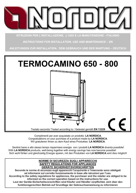
<strong>TERMOCAMINO</strong> <strong>650</strong> - <strong>800</strong><br />
Testato secondo/ Tested according to / Getestet gemäß EN 13229<br />
|<br />
Complimenti per aver acquistato un prodotto: LA NORDICA.<br />
Congratulations on your purchase of a product made by LA NORDICA.<br />
Wir gratulieren Ihnen zu dem Kauf eines Produktes: LA NORDICA.<br />
•<br />
Sentirsi bene e allo stesso tempo risparmiare energia con i prodotti LA NORDICA diventa possibile!<br />
With LA NORDICA products, well-being together with energy savings has now become possible!<br />
Sich wohl fühlen und gleichzeitig Energie sparen, mit den Produkten von LA NORDICA wird dies möglich!<br />
NORME DI SICUREZZA SUGLI APPARECCHI<br />
SAFETY REGULATIONS FOR APPLIANCES<br />
GERÄTE SICHERHEITSVORSCHRIFTEN<br />
Secondo le norme di sicurezza sugli apparecchi l’acquirente e l’esercente sono obbligati<br />
ad informarsi sul corretto funzionamento in base alle istruzioni per l’uso.<br />
According to the safety regulations for appliances, the purchaser and the retailer are obliged to be<br />
informed on the correct operation based on the instructions for use.<br />
Laut der Geräte-Sicherheitsvorschriften sind Käufer und Händler verpflichtet, sich über den<br />
funktionsgerechten Betrieb auf Grundlage der Gebrauchsanweisung zu informieren
Termocamino <strong>650</strong> - <strong>800</strong><br />
IMPORTANTE<br />
RIMUOVERE DAL <strong>TERMOCAMINO</strong> LE DUE VITI CHE BLOCCANO I CONTRAPPESI PER IL<br />
MOVIMENTO DELLA PORTA POSIZIONATE NEI LATI COME INDICATO IN FIGURA .<br />
IMPORTANT<br />
REMOVE THE TWO SCREWS FROM THERMO-FIREPLACE TO UNLOACK THE<br />
COUNTERWEIGHTS ON BOTH SIDES, AS INDICATED IN THE PICTURE, IN ORDER TO<br />
MOVE THE DOOR.<br />
WICHTIG<br />
VOM THERMOKAMIN DIE BEIDEN SCHRAUBEN ENTFERNEN, DIE DIE GEGENGEWICHTE<br />
ZUR BEWEGUNG DER TÜRE BLOCKIEREN, DIESE BEFINDEN SICH AN DEN SEITEN, WIE<br />
IN DER ABBILDUNG DARGESTELLT<br />
2 Istruzioni per l’installazione / Instruction Manual / Anweisungen – Rev.07 – IT – EN
Termocamino <strong>650</strong> - <strong>800</strong><br />
INDICE<br />
IT<br />
1. AVVERTENZE GENERALI ................................................................................................................................................. 6<br />
2. DESCRIZIONE................................................................................................................................................................... 6<br />
3. NORME PER L’INSTALLAZIONE ....................................................................................................................................... 6<br />
4. SICUREZZA ANTINCENDIO .............................................................................................................................................. 7<br />
4.1. PRONTO INTERVENTO ............................................................................................................................................ 8<br />
4.2. PROTEZIONI DELLE TRAVI ...................................................................................................................................... 8<br />
5. CANNA FUMARIA.............................................................................................................................................................. 9<br />
5.1. COMIGNOLO........................................................................................................................................................... 10<br />
6. COLLEGAMENTO ALLA CANNA FUMARIA ..................................................................................................................... 11<br />
7. AFLUSSO D’ARIA NEL LUOGO D’INSTALLAZIONE DURANTE LA COMBUSTIONE........................................................ 12<br />
8. INSTALLAZIONE E DISPOSITIVI DI SICUREZZA............................................................................................................. 13<br />
8.1. COLLEGAMENTO E CARICO DELL’IMPIANTO – Capitolo 18 .................................................................................. 15<br />
9. COMBUSTIBILI AMMESSI / NON AMMESSI .................................................................................................................... 16<br />
10. ACCENSIONE E PROVA DI FUNZIONALITÀ ............................................................................................................... 16<br />
11. FUNZIONAMENTO NORMALE .................................................................................................................................... 17<br />
12. FUNZIONAMENTO NEI PERIODI DI TRANSIZIONE .................................................................................................... 18<br />
13. UTILIZZO CORRETTO PER IL RISCALDAMENTO CENTRALIZZATO.......................................................................... 18<br />
14. MANCANZA DI ENERGIA ELETTRICA......................................................................................................................... 19<br />
15. MANUTENZIONE E CURA........................................................................................................................................... 19<br />
15.1. PULIZIA DELLA CANNA FUMARIA.......................................................................................................................... 19<br />
15.2. PULIZIA DEL VETRO............................................................................................................................................... 20<br />
15.3. PULIZIA CASSETTO CENERE................................................................................................................................. 20<br />
15.4. MANUTENZIONE GUIDE ESTENSIBILI ................................................................................................................... 20<br />
15.5. MANUTENZIONE DELL’IMPIANTO IDRAULICO ...................................................................................................... 20<br />
16. FERMO ESTIVO .......................................................................................................................................................... 21<br />
17. DETERMINAZIONE DELLA POTENZA TERMICA ........................................................................................................ 21<br />
18. L’IMPIANTO / THE SYSTEM / INSTALLATION SCHEME.............................................................................................. 54<br />
19. SCHEDE TECNICHE / TECHNICAL DIAGRAMS – <strong>TERMOCAMINO</strong> <strong>650</strong>...................................................................... 58<br />
20. SCHEDE TECNICHE / TECHNICAL DIAGRAMS – <strong>TERMOCAMINO</strong> <strong>800</strong>...................................................................... 59<br />
21. CARATTERISTICHE TECNICHE <strong>TERMOCAMINO</strong> <strong>650</strong> ................................................................................................ 60<br />
22. CARATTERISTICHE TECNICHE <strong>TERMOCAMINO</strong> <strong>800</strong> ................................................................................................ 61<br />
CONTENTS<br />
EN<br />
1. GENERAL PRECAUTIONS .............................................................................................................................................. 22<br />
2. DESCRIPTION................................................................................................................................................................. 22<br />
3. INSTALLATION CHECKS................................................................................................................................................. 22<br />
4. FIRE PREVENTION ......................................................................................................................................................... 23<br />
4.1. EMERGENCY PROCEDURES................................................................................................................................. 24<br />
4.2. PROTECTING THE BEAMS..................................................................................................................................... 24<br />
5. FLUE ............................................................................................................................................................................... 25<br />
5.1. CHIMNEY CAP ........................................................................................................................................................ 26<br />
6. CONNECTION TO THE FLUE .......................................................................................................................................... 27<br />
7. EXTERNAL AIR INTAKE IN THE INSTALLATION AREA DURING COMBUSTION ............................................................ 28<br />
8. INSTALLATION AND SAFETY DEVICES.......................................................................................................................... 29<br />
8.1. SYSTEM CONNECTION AND FILLING – Chapter 18 ............................................................................................... 31<br />
9. ADMISSIBLE / PROHIBITED FUELS................................................................................................................................ 32<br />
10. LIGHTING AND FUNCTIONAL TEST ........................................................................................................................... 32<br />
11. NORMAL OPERATION ................................................................................................................................................ 33<br />
12. OPERATION IN THE TRANSITION PERIODS.............................................................................................................. 34<br />
13. CORRECT USE FOR CENTRAL HEATING .................................................................................................................. 34<br />
14. ELECTRICAL POWER SUPPLY FAILURE ................................................................................................................... 34<br />
15. MAINTENANCE AND CARE......................................................................................................................................... 35<br />
15.1. FLUE CLEANING..................................................................................................................................................... 35<br />
15.2. GLASS CLEANING .................................................................................................................................................. 35<br />
15.3. CLEANING OUT THE ASHES.................................................................................................................................. 35<br />
15.4. MAINTENANCE ON THE EXTENDIBLE GUIDES..................................................................................................... 35<br />
15.5. MAINTENANCE ON THE WATER SYSTEM............................................................................................................. 36<br />
16. SUMMER SET ASIDE.................................................................................................................................................. 36<br />
17. DETERMINING THE HEATING POWER ...................................................................................................................... 36<br />
18. L’IMPIANTO / THE SYSTEM / INSTALLATION SCHEME.............................................................................................. 54<br />
19. SCHEDE TECNICHE / TECHNICAL DIAGRAMS – <strong>TERMOCAMINO</strong> <strong>650</strong>...................................................................... 58<br />
20. SCHEDE TECNICHE / TECHNICAL DIAGRAMS – <strong>TERMOCAMINO</strong> <strong>800</strong>...................................................................... 59<br />
21. CARATTERISTICHE TECNICHE <strong>TERMOCAMINO</strong> <strong>650</strong> ................................................................................................ 60<br />
22. CARATTERISTICHE TECNICHE <strong>TERMOCAMINO</strong> <strong>800</strong> ................................................................................................ 61<br />
Istruzioni per l’installazione / Instruction Manual / Anweisungen – Rev.07 – IT – EN 3
Termocamino <strong>650</strong> - <strong>800</strong><br />
INHALTSANGABE<br />
DE<br />
1. ALLGEMEINE HINWEISE................................................................................................................................................. 37<br />
2. BESCHREIBUNG............................................................................................................................................................. 37<br />
3. INSTALLATIONSNORMEN............................................................................................................................................... 38<br />
4. BRANDSCHUTZ .............................................................................................................................................................. 38<br />
4.1. NOTHILFEINTERVENTION...................................................................................................................................... 39<br />
4.2. TRÄGERSCHUTZ.................................................................................................................................................... 39<br />
5. SCHORNSTEINROHR ..................................................................................................................................................... 40<br />
5.1. SCHORNSTEIN....................................................................................................................................................... 41<br />
6. VERBINDUNG ZUM SCHORNSTEINROHR ..................................................................................................................... 43<br />
7. ABLEITEN DER LUFT AUS DEM ORT DER INSTALLATION WÄHREND DER VERBRENNUNG...................................... 44<br />
8. INSTALLATION UND SICHERHEITSVORRICHTUNGEN.................................................................................................. 45<br />
8.1. VERBINDUNG UND LADEN DER ANLAGE – Kapitel 18........................................................................................... 47<br />
9. ZULÄSSIGE / UNZULÄSSIGE BRENNSTOFFE................................................................................................................ 48<br />
10. EINSCHALTEN UND KONTROLLE DER FUNKTIONSTÜCHTIGKEIT........................................................................... 48<br />
11. NORMALER BETRIEB ................................................................................................................................................. 49<br />
12. BETRIEB IN DEN ÜBERGANGSPERIODEN ................................................................................................................ 50<br />
13. KORREKTER GEBRAUCH BEI ZENTRALHEIZUNG .................................................................................................... 50<br />
14. STROMAUSFALL......................................................................................................................................................... 51<br />
15. WARTUNG UND PFLEGE............................................................................................................................................ 51<br />
15.1. REINIGUNG DES SCHORNSTEINROHRES ............................................................................................................ 51<br />
15.2. REINIGUNG DES GLASES...................................................................................................................................... 52<br />
15.3. REINIGUNG DES ASCHENKASTENS...................................................................................................................... 52<br />
15.4. WARTUNG DER AUSZIEHBAREN FÜHRUNGEN.................................................................................................... 52<br />
15.5. WARTUNG DER HYDRAULIKANLAGE.................................................................................................................... 52<br />
16. SOMMERLICHE STILLLEGUNG .................................................................................................................................. 53<br />
17. BESTIMMUNG DER WÄRMELEISTUNG...................................................................................................................... 53<br />
18. L’IMPIANTO / THE SYSTEM / INSTALLATION SCHEME.............................................................................................. 54<br />
19. SCHEDE TECNICHE / TECHNICAL DIAGRAMS – <strong>TERMOCAMINO</strong> <strong>650</strong>...................................................................... 58<br />
20. SCHEDE TECNICHE / TECHNICAL DIAGRAMS – <strong>TERMOCAMINO</strong> <strong>800</strong>...................................................................... 59<br />
21. CARATTERISTICHE TECNICHE <strong>TERMOCAMINO</strong> <strong>650</strong> ................................................................................................ 60<br />
22. CARATTERISTICHE TECNICHE <strong>TERMOCAMINO</strong> <strong>800</strong> ................................................................................................ 61<br />
4 Istruzioni per l’installazione / Instruction Manual / Anweisungen – Rev.07 – IT – EN
Termocamino <strong>650</strong> - <strong>800</strong><br />
DICHIARAZIONE DI CONFORMITA’ DEL COSTRUTTORE<br />
Oggetto: assenza di amianto e cadmio<br />
Si dichiara che tutti i nostri apparecchi vengono assemblati con materiali che non presentano parti<br />
di amianto o suoi derivati e che nel materiale d’apporto utilizzato per le saldature non è<br />
presente/utilizzato in nessuna forma il cadmio, come previsto dalla norma di riferimento.<br />
Oggetto: Regolamento CE n. 1935/2004<br />
Si dichiara che in tutti gli apparecchi da noi prodotti, i materiali destinati a venire a contatto con i<br />
cibi sono adatti all’uso alimentari, in conformità al Regolamento CE in oggetto.<br />
MANUFACTURER’S DECLARATION OF CONFORMITY<br />
Object: absence of asbestos and cadmium<br />
We declare that all our appliances are assembled with materials which do not have parts made of asbestos<br />
or its derivatives and that in the weld metal used for welding, cadmium is not present, nor is it used in any<br />
form, as required by the reference regulation.<br />
Object: EC REGULATION no. 1935/2004<br />
We declare that in all the appliances which we produce, the materials which are intended to come into<br />
contact with food are suitable for use with food products, in conformity with the EC Regulation in<br />
question.<br />
KONFORMITÄTSERKLÄRUNG DES HERSTELLERS<br />
Betreff: Fehlen von Amiant und Kadmium<br />
Wir erklären, dass alle Materialien, die zur Herstellung unserer Geräte verwendet werden ohne Asbest<br />
oder Derivate sind und dass das Lot für die Schweißarbeiten immer ohne Radium ist, wie von den<br />
Bezugsnormen vorgesehen.<br />
Betreff: EG Verordnung Nr. 1935/2004<br />
Wir erklären, dass die in allen von uns hergestellten Geräte, die Teile die in Kontakt mit Lebensmitteln<br />
kommen, für zur Lebensmittelbenutzung geeignet sind, in Konformität mit der betreffenden EG<br />
Verordnung.<br />
Istruzioni per l’installazione / Instruction Manual / Anweisungen – Rev.07 – IT – EN 5
Termocamino <strong>650</strong> - <strong>800</strong><br />
1. AVVERTENZE GENERALI<br />
L’installazione di un camino deve avvenire in conformità alle leggi e ai regolamenti di ciascun paese.<br />
Per l’Italia la norma attualmente vigente è la UNI 10683 del 1998<br />
La nostra responsabilità è limitata alla fornitura dell’apparecchio.<br />
Il suo impianto va realizzato in modo conforme alla regola dell’arte, secondo le prescrizioni delle<br />
presenti istruzioni e le regole della professione, da personale qualificato, che agisce a nome di<br />
imprese adatte ad assumere l'intera responsabilità dell'insieme dell'impianto.<br />
La Nordica S.p.A. non è responsabile del prodotto modificato<br />
senza autorizzazione e tanto meno per l’uso di ricambi non<br />
originali.<br />
IMPORTANTE: per ottenere il migliore rendimento, bisogna<br />
predisporre all’interno del focolare i ceppi di legna da ardere, di<br />
lunghezza massima pari a 30 cm, come indicato in Figura 1.<br />
2. DESCRIZIONE<br />
Figura 1<br />
Definizione: termocamino secondo EN 13229<br />
L’apparecchio è composto da lastre in lamiera d’acciaio verniciato,<br />
zincata e da fusioni di ghisa.<br />
Il corpo caldaia è in acciaio di 4 mm di spessore mentre il piano fuoco e la relativa griglia estraibile sono<br />
entrambi in ghisa.<br />
Gli apparecchi dispongono di un deflettore fumi, inserito tra i<br />
due tubi cilindrici superiori, facilmente estraibile per una<br />
veloce ed agevole pulizia della parte interna. La camera di<br />
combustione circolare è dotata di una schiena centrale forata<br />
in ghisa.<br />
Attraverso questi fori arriva all’interno del focolare dell’aria<br />
preriscaldata, si ottiene così una post-combustione con un<br />
aumento del rendimento ed una riduzione di emissioni dei<br />
gas incombusti.<br />
La porta panoramica è montata su guide estensibili a sfere le<br />
quali garantiscono un funzionamento robusto, silenzioso ed A<br />
affidabile nel tempo.<br />
Il contrappeso di sollevamento della porta è sostenuto da due<br />
robuste catene con relativi pignoni.<br />
Il vetro ceramico (resistente fino 700 C) della porta, consente<br />
MIN MAX<br />
un’affascinante vista sulle fiamme ardenti ed impedisce ogni<br />
ARIA PRIMARIA<br />
fuoriuscita di scintille e fumo.<br />
L’apparecchio è dotato di un registro per l’aria primaria<br />
Figura 2<br />
regolabile. L’aria secondaria e terziaria sono predeterminate.<br />
- Registro aria primaria (Figura 2 pos.A)<br />
Con il registro per l’aria primaria posto sotto la porta del focolare viene regolato il passaggio dell’aria<br />
attraverso il cassetto cenere e la griglia in direzione del combustibile. L’aria primaria è necessaria per il<br />
processo di combustione. Con il registro in posizione tutto a destra l’aria è tutta aperta.<br />
Il cassetto cenere deve essere svuotato regolarmente, in modo che la cenere non possa ostacolare<br />
l’entrata dell’aria primaria per la combustione. Attraverso l’aria primaria viene anche mantenuto vivo il<br />
fuoco.<br />
3. NORME PER L’INSTALLAZIONE<br />
Il termocamino deve essere installato rispettando la norma 10683 del 1998. L’installazione, i relativi<br />
collegamenti dell’impianto, la messa in servizio, e la verifica del buon funzionamento devono<br />
essere eseguiti a regola d’arte da personale professionalmente qualificato (LEGGE 5 MARZO 1990<br />
N°46 ) nel pieno rispetto delle normative vigenti n onché delle presenti istruzioni.<br />
6 Istruzioni per l’installazione, l’uso e la manutenzione – Rev.07 – IT
Termocamino <strong>650</strong> - <strong>800</strong><br />
La Nordica S.p.A. declina ogni responsabilità per danni a cose e/o persone provocati dall’impianto.<br />
Inoltre non è responsabile del prodotto modificato senza autorizzazione e tanto meno per l’uso di<br />
ricambi non originali.<br />
Il Vostro abituale spazzacamino di zona deve essere informato sull’installazione dell’apparecchio, affinché<br />
possa verificare il regolare collegamento alla canna fumaria ed il grado di efficienza di quest’ultima.<br />
Prima dell’installazione eseguire le seguenti verifiche:<br />
• accertarsi che il pavimento possa sostenere il peso dell’apparecchio e provvedere ad un adeguato<br />
isolamento nel caso sia costruito in materiale infiammabile.<br />
• assicurarsi che nella stanza dove sarà<br />
installato vi sia una ventilazione adeguata<br />
(presenza di presa d’aria vedi capitolo 7)<br />
• evitare l’installazione in locali con presenza di<br />
condotti di ventilazione collettivo, cappe con o<br />
senza estrattore, apparecchi a gas di tipo B,<br />
pompe di calore o la presenza di apparecchi il<br />
cui funzionamento contemporaneo possa<br />
mettere in depressione il locale (rif. Norma<br />
UNI 10683/98)<br />
• accertarsi che la canna fumaria e i tubi a cui<br />
verrà collegato l’apparecchio siano idonei al<br />
funzionamento dello stesso.<br />
• lasciare sempre minimo 6cm lateralmente e<br />
posteriormente di vuoto d’aria tra il<br />
termocamino e le pareti. (vedi Figura 3 -<br />
Figura 13 - Figura 14)<br />
• Tramite i piedini regolabili e mediante<br />
l’impiego di una livella assicurarsi che<br />
l’apparecchio sia perfettamente in piano per<br />
permettere un corretto scorrimento della porta.<br />
Vi consigliamo di far verificare dal Vostro abituale<br />
spazzacamino di zona sia il collegamento al<br />
camino sia il sufficiente afflusso d’aria per la<br />
combustione nel luogo d’installazione.<br />
Vedi anche capitolo 8-INSTALLAZIONE E DISPOSITIVI DI SICUREZZA<br />
4. SICUREZZA ANTINCENDIO<br />
Figura 3<br />
min. 5cm 6cm<br />
Nell’installazione dell’apparecchio devono essere osservate le seguenti misure di sicurezza:<br />
a) davanti al termocamino non deve esserci alcun oggetto o materiale di costruzione infiammabile e<br />
sensibile al calore a meno di 80 cm di distanza;<br />
b) qualora l’apparecchio dovesse essere installato su di un pavimento non completamente refrattario,<br />
bisogna prevedere un sottofondo ignifugo, per esempio una pedana d'acciaio (dimensioni secondo<br />
l’ordinamento regionale. (vedi Figura 4)<br />
Il termocamino deve funzionare esclusivamente con il cassetto cenere inserito.<br />
I residui solidi della combustione (ceneri) devono essere raccolti in un contenitore ermetico e resistente al<br />
fuoco. L’apparecchio non deve mai essere acceso in presenza di emissioni gassose o vapori (per esempio<br />
colla per linoleum, benzina ecc.). Non depositate materiali infiammabili nelle vicinanze dello stesso.<br />
Durante la combustione viene sprigionata energia termica che comporta un marcato riscaldamento delle<br />
superfici, della porta e del vetro del focolare, delle maniglie delle porte o di comando, del tubo fumi ed<br />
eventualmente della parte anteriore dell’apparecchio. Evitate il contatto con tali elementi senza un<br />
corrispondente abbigliamento protettivo o senza utensili accessori (guanti resistenti al calore, dispositivi di<br />
comando).<br />
Istruzioni per l’installazione, l’uso e la manutenzione – Rev.07 – IT 7
Termocamino <strong>650</strong> - <strong>800</strong><br />
Protezione del pavimento con<br />
materiale incombustibile<br />
Altezza da terra del<br />
piano del focolare<br />
Pavimentazione in<br />
materiale combustibile<br />
A<br />
H<br />
B<br />
A=Limite laterale della zona protetta (A=H+20 cm=> 40 cm)<br />
B=Limite frontale della zona protetta (B=H+30 cm=> 60 cm)<br />
Figura 4<br />
Fate in modo che i bambini siano consapevoli di questi pericoli e teneteli lontani dal focolare<br />
durante il suo funzionamento .<br />
Quando si utilizza un combustibile errato o troppo umido si potrebbero formare dei depositi (creosoto) nella<br />
canna fumaria con possibile incendio della canna fumaria stessa.<br />
Avvertire i bambini che l’apparecchio diventa molto caldo e che non deve essere toccato.<br />
4.1. PRONTO INTERVENTO<br />
Se si manifesta un incendio nel camino o nella canna fumaria:<br />
a) Chiudere la porta di caricamento.<br />
b) Chiudere i registri d’aria comburente<br />
c) Spegnere tramite l’uso di estintori ad anidride carbonica (CO 2 a polveri )<br />
d) Richiedere l’immediato intervento dei VIGILI del FUOCO<br />
NON SPEGNERE IL FUOCO CON L’USO DI GETTI D’ACQUA.<br />
Quando la canna fumaria smette di bruciare, farla verificare da uno specialista per individuare eventuali<br />
crepe o punti permeabili.<br />
4.2. PROTEZIONI DELLE TRAVI<br />
Tenendo conto dell’irradiazione del focolare, dovete essere particolarmente attenti alla protezione delle<br />
travi nella progettazione del vostro camino, tenete conto da una parte della prossimità della trave dalle<br />
facce esterne del focolare, e dall’altra dell’irradiazione della porta in vetro che normalmente è molto vicina<br />
alle travi stesse. Sappiate che in qualsiasi caso, le facce interne o inferiori di questa trave in materiale<br />
combustibile non devono essere in contatto con temperature superiori ai 65 °C.<br />
(3) 10 mm<br />
(1)<br />
(3) 10 mm<br />
(1)<br />
(3) 10 mm<br />
(1)<br />
(2)<br />
(2)<br />
(2)<br />
(4)<br />
(1)<br />
(3) 10 ÷ 50 mm<br />
(1)<br />
(3) 10 mm<br />
(3) 10 mm<br />
(1)<br />
(2)<br />
(2)<br />
(2)<br />
(4)<br />
(1) Trave; (2) Isolante materiale refrattario; (3) Vuoto d’aria; (4) Protezione metallica.<br />
Figura 5<br />
AVVERTENZA:<br />
Non potremo essere ritenuti responsabili per un cattivo funzionamento dell’impianto non conforme<br />
alle prescrizioni delle presenti istruzioni o ancora dall’uso di prodotti complementari non adatti.<br />
In Figura 5 sono riportati alcuni esempi di soluzione.<br />
8 Istruzioni per l’installazione, l’uso e la manutenzione – Rev.07 – IT
Termocamino <strong>650</strong> - <strong>800</strong><br />
5. CANNA FUMARIA<br />
Requisiti fondamentali per un corretto funzionamento dell’apparecchio:<br />
• la sezione interna deve essere preferibilmente circolare;<br />
• la sezione interna deve essere termicamente isolata ed<br />
impermeabile e costruita con materiali idonei a resistere al<br />
calore, ai prodotti della combustione ed alle eventuali<br />
condense;<br />
• la sezione interna deve essere priva di strozzature ed avere<br />
andamento verticale con deviazioni non superiori a 45°;<br />
• la sezione interna se già usata deve essere pulita;<br />
• bisogna rispettare i dati tecnici del manuale di istruzioni;<br />
Qualora le canne fumarie fossero a sezione quadrata o rettangolare gli<br />
spigoli interni devono essere arrotondati con raggio non inferiore a 20<br />
mm. Per la sezione rettangolare il rapporto massimo tra i lati deve<br />
essere = 1,5. Una sezione troppo piccola provoca una diminuzione del<br />
tiraggio.<br />
Si consiglia un’altezza minima di 4 m.<br />
Sono vietate e pertanto pregiudicano il buon funzionamento<br />
dell’apparecchio: fibrocemento, acciaio zincato,superfici interne ruvide<br />
e porose. In Figura 6 sono riportati alcuni esempi di soluzione.<br />
(1) (2)<br />
La sezione minima deve essere di 4 dm2 (per esempio 20 x 20<br />
cm) per gli apparecchi il cui diametro di condotto è inferiore a 200<br />
mm o 6,25 dm2 (per esempio 25 x 25 cm) per gli apparecchi con<br />
diametro superiore a 200 mm. Figura 6<br />
(3)<br />
(4)<br />
Max. A+1/2A<br />
A+1/2A<br />
1. Canna fumaria in acciaio AISI 316<br />
con doppia camera isolata con<br />
materiale resistente a<br />
400°C. Efficienza 100% ottima.<br />
2. Canna fumaria in refrattario con<br />
doppia camera isolata e<br />
rivestimento esterno in<br />
calcestruzzo alleggerito.<br />
Efficienza 100% ottima.<br />
3. Canna fumaria tradizionale in argilla<br />
sezione quadrata con<br />
intercapedini. Efficienza 80%<br />
ottima.<br />
4. Evitare canne fumarie con sezione<br />
rettangolare interna il cui rapporto<br />
sia diverso dal disegno<br />
(MAX=A+½A).<br />
Efficienza 40% mediocre.<br />
A<br />
SI<br />
NO<br />
(1) Sportello<br />
per<br />
pulizia<br />
(2) Rappresentazione di canna fumaria corretta<br />
con sportello a tenuta per la raccolta e lo scarico<br />
dei materiali solidi incombusti.<br />
Figura 7<br />
(1) Sconsigliato il collegamento alla canna<br />
fumaria di più apparecchi.<br />
Ciascuno deve poter usufruire di una propria<br />
canna fumaria.<br />
Figura 8<br />
Istruzioni per l’installazione, l’uso e la manutenzione – Rev.07 – IT 9
Termocamino <strong>650</strong> - <strong>800</strong><br />
Il tiraggio creato dalla vostra canna fumaria deve essere sufficiente ma non eccessivo.<br />
Una sezione della canna fumaria troppo importante può presentare un volume troppo grande da riscaldare<br />
e dunque provocare delle difficoltà di funzionamento dell’apparecchio; per evitare ciò provvedete ad<br />
intubare la stessa per tutta la sua altezza. Una sezione troppo piccola provoca una diminuzione del<br />
tiraggio.<br />
La canna fumaria deve essere adeguatamente distanziata da materiali infiammabili o combustibili<br />
mediante un opportuno isolamento o un’intercapedine d’aria.<br />
E’ vietato far transitare all’interno della stessa tubazioni di impianti o canali di adduzione d’aria. E’ proibito<br />
inoltre praticare aperture mobili o fisse sulla stessa, per il collegamento di ulteriori apparecchi diversi .<br />
5.1. COMIGNOLO<br />
Il tiraggio della canna fumaria dipende anche dall’idoneità del comignolo.<br />
È pertanto indispensabile che, se costruito artigianalmente, la sezione di uscita sia più di due volte la<br />
sezione interna della canna fumaria.<br />
Dovendo sempre superare il colmo del tetto, il comignolo dovrà assicurare lo scarico anche in presenza di<br />
vento (vedi Figura 9)<br />
(1) Comignolo industriale<br />
ad elementi prefabbricati,<br />
consente un ottimo<br />
smaltimento dei fumi.<br />
(2) Comignolo<br />
artigianale. La giusta<br />
sezione di uscita<br />
deve essere minimo<br />
2 volte la sezione<br />
interna della canna<br />
fumaria, ideale 2,5<br />
volte.<br />
(3) Comignolo per canna<br />
fumaria in acciaio con cono<br />
interno deflettore dei fumi.<br />
Figura 9<br />
Il comignolo deve rispondere ai seguenti requisiti:<br />
• avere sezione interna equivalente a quella del camino.<br />
• avere sezione utile d’uscita doppia di quella interna della canna fumaria.<br />
• essere costruito in modo da impedire la penetrazione nella canna fumaria di pioggia, neve e di<br />
qualsiasi corpo estraneo.<br />
• essere facilmente ispezionabile, per eventuali operazioni di manutenzione e pulizia.<br />
50 cm (1) In caso di canne fumarie affiancate un comignolo dovrà sovrastare<br />
l’altro d’almeno 50 cm al fine d’evitare trasferimenti di pressione tra le<br />
canne stesse.<br />
Figura 10<br />
2 m 10 m<br />
1<br />
m<br />
(1) Il comignolo non deve avere ostacoli entro i 10 m da muri, falde ed<br />
alberi. In caso contrario innalzare lo stesso d’almeno 1 m sopra<br />
l’ostacolo.<br />
Il comignolo deve oltrepassare il colmo del tetto d’almeno 1 m.<br />
Figura 11<br />
10 Istruzioni per l’installazione, l’uso e la manutenzione – Rev.07 – IT
Termocamino <strong>650</strong> - <strong>800</strong><br />
> _ A<br />
>A<br />
0,5 m<br />
H min.<br />
(1)Asse colmo<br />
α<br />
(2)Tetto<br />
Figura 12<br />
COMIGNOLI DISTANZE E POSIZIONAMENTO UNI 10683/98<br />
Inclinazione del tetto<br />
Distanza tra il colmo e il camino<br />
Altezza minima del camino<br />
(misurata dallo sbocco)<br />
α A (m) H (m)<br />
15°<br />
30°<br />
45°<br />
60°<br />
< 1,85 m 0,50 m oltre il colmo<br />
> 1,85 m 1,00 m dal tetto<br />
< 1,50 m 0,50 m oltre il colmo<br />
> 1,50 m 1,30 m dal tetto<br />
< 1,30 m 0,50 m oltre il colmo<br />
> 1,30 m 2,00 m dal tetto<br />
< 1,20 m 0,50 m oltre il colmo<br />
> 1,20 m 2,60 m dal tetto<br />
6. COLLEGAMENTO ALLA CANNA FUMARIA<br />
Il collegamento (canale da fumo o raccordo) alla canna fumaria deve essere eseguito con tubi rigidi in<br />
acciaio alluminato con spessore minimo di 2 mm oppure in acciaio Inox 316 con spessore minimo di 1 mm.<br />
È vietato l’uso di tubi flessibili metallici o in fibrocemento poiché pregiudicano la sicurezza del<br />
raccordo stesso in quanto sono soggetti a strappi o rotture causando perdite di fumo.<br />
Il tubo di scarico fumi deve essere fissato ermeticamente al camino e può avere un’inclinazione massima<br />
di 45°, questo per evitare depositi eccessivi di co ndensa prodotta nelle fasi iniziali d’accensione e/o<br />
l’aggrappaggio eccessivo di fuliggine ed inoltre evita il rallentamento dei fumi in uscita.<br />
La non ermeticità del collegamento può causare il malfunzionamento dell’apparecchio.<br />
Il diametro interno del tubo di collegamento deve corrispondere al diametro esterno del tronchetto di<br />
scarico fumi dell’apparecchio. Ciò viene garantito dai tubi secondo DIN 1298.<br />
La depressione al camino dovrebbe essere 17 – 20 Pa ( 1,7 – 2 mm di colonna d’acqua).<br />
La misurazione deve essere fatta sempre ad apparecchio caldo (resa calorifica nominale).<br />
Quando la depressione supera 20 Pa ( 2 mm di colonna d’acqua) è necessario ridurre la stessa con<br />
l’installazione di un regolatore di tiraggio supplementare (valvola a farfalla) sul tubo di scarico o nel camino.<br />
Istruzioni per l’installazione, l’uso e la manutenzione – Rev.07 – IT 11
Termocamino <strong>650</strong> - <strong>800</strong><br />
IMPORTANTE:<br />
Con l’utilizzo di tubi metallici è indispensabile che questi siano isolati con materiali idonei<br />
(rivestimenti in fibra isolante resistenti fino a 600° C) al fine di evitare deterioramenti delle mura ture<br />
o della controcappa.<br />
E’ indispensabile che lo spazio compreso tra la parte<br />
superiore, i lati dell’apparecchio ed il deflettore di materiale<br />
incombustibile della cappa, sia costantemente ventilato.<br />
Bisogna per questo motivo consentire un’entrata di aria dal<br />
basso (entrata di aria fresca) ed un’uscita alta (uscita d’aria<br />
calda).<br />
Gli spazi previsti per la circolazione dell’aria indicati nella<br />
Figura 13 sono i requisiti minimi:<br />
Sommità: apertura minima 1000 cm2<br />
Base: apertura minima 750 cm2<br />
1000 cm<br />
2<br />
Si otterrà quindi:<br />
• una maggiore sicurezza<br />
• un aumento del calore creato dalla circolazione<br />
d’aria attorno all’apparecchio.<br />
ATTENZIONE si consiglia la realizzazione della<br />
controcappa in cartongesso ignifugo con telaio metallico<br />
autoportante, in maniera da non far gravare il suo peso sul<br />
rivestimento estetico stesso (marmo).<br />
Figura 13<br />
750 cm<br />
2<br />
5 cm min post. e laterale<br />
6<br />
La griglia di sfiato calore (Figura 14 pos. 6 ) va installata<br />
sulla parte superiore della cappa a circa 20 cm dal soffitto. Questa deve sempre essere installata in<br />
quanto la sua funzione è quella di lasciare fuoriuscire nel locale il calore accumulato all’interno della cappa<br />
(sovrapressione).<br />
7. AFLUSSO D’ARIA NEL LUOGO D’INSTALLAZIONE DURANTE LA<br />
COMBUSTIONE<br />
Per un buon funzionamento dell’apparecchio è essenziale che nel luogo d’installazione venga immessa<br />
sufficiente aria per la combustione e la riossigenazione dell’ambiente stesso. Ciò significa che, attraverso<br />
apposite aperture comunicanti con l’esterno, deve poter circolare aria per la combustione anche a porte e<br />
finestre chiuse.<br />
(1) Isolante<br />
(2) Sigillare<br />
(3) Rivestimento isolante provvisto<br />
di foglio di alluminio esterno<br />
(6) Griglia sfiato calore<br />
(7) Controcappa ignifuga<br />
(8) Inclinazione massima 45°<br />
(4) Sportello per pulizia<br />
(9) Schermare le parti in legno<br />
con materiale isolante<br />
(5) Presa aria esterna<br />
(10) Distanze posteriori e laterali<br />
min 6 cm<br />
Figura 14<br />
12 Istruzioni per l’installazione, l’uso e la manutenzione – Rev.07 – IT
Termocamino <strong>650</strong> - <strong>800</strong><br />
• La presa d’aria deve essere posizionata in modo da non poter essere ostruita<br />
• La presa d’aria deve essere comunicante con il locale d’installazione dell’apparecchio ed<br />
essere protetta con una griglia.<br />
• Qualora l’afflusso dell’aria fosse ottenuto attraverso aperture comunicanti con locali<br />
adiacenti sono da evitare (VIETATO) prese d’aria in collegamento con garage, cucine, bagni,<br />
centrali termiche.<br />
Dimensioni minime: - Termocamino <strong>800</strong> : ∅ 250 / 300 mm<br />
- Termocamino <strong>650</strong> : ∅ 200 / 250 mm<br />
Figura 15 Figura 16<br />
8. INSTALLAZIONE E DISPOSITIVI DI SICUREZZA<br />
L’installazione del termocamino e degli equipaggiamenti ausiliari, relativi all’impianto di<br />
riscaldamento, deve essere conforme e tutte le Norme e Regolamentazioni attuali ed a quanto<br />
previsto dalla Legge.<br />
L’installazione, i relativi collegamenti dell’impianto, la messa in servizio e la verifica del corretto<br />
funzionamento devono essere eseguiti a regola d’arte da personale professionalmente autorizzato<br />
nel pieno rispetto delle norme vigenti, sia nazionali, regionali, provinciali e comunali presenti nel paese in<br />
cui è stato installato l’apparecchio, nonché delle presenti istruzioni.<br />
L’installazione deve essere eseguita da personale autorizzato, che dovrà rilasciare all’acquirente una<br />
dichiarazione di conformità dell’impianto, il quale si assumerà l’intera responsabilità dell’installazione<br />
definitiva e del conseguente buon funzionamento del prodotto installato.<br />
Non vi sarà responsabilità da parte di La NORDICA S.p.A. in caso di mancato rispetto di tali precauzioni.<br />
Prima dell’installazione, si consiglia di effettuare un lavaggio accurato di tutte le tubazioni dell’impianto<br />
onde rimuovere eventuali residui che potrebbero compromettere il buon funzionamento dell’apparecchio.<br />
IMPORTANTE:<br />
a) In caso di fuoriuscite d’acqua chiudere l’alimentazione idrica ed avvisare con sollecitudine il servizio<br />
tecnico di assistenza;<br />
b) La pressione di esercizio dell’impianto deve essere periodicamente controllata.<br />
c) In caso di non utilizzo della caldaia per un lungo periodo è consigliabile l’intervento del servizio tecnico<br />
di assistenza per effettuare almeno le seguenti operazioni:<br />
- chiudere i rubinetti dell’acqua sia dell’impianto termico sia del sanitario;<br />
- svuotare l’impianto termico e sanitario se c’è rischio di gelo.<br />
Istruzioni per l’installazione, l’uso e la manutenzione – Rev.07 – IT 13
Termocamino <strong>650</strong> - <strong>800</strong><br />
La Nordica S.p.a. declina ogni responsabilità per danni a cose e/o persone provocati dall’impianto.<br />
Inoltre non è responsabile del prodotto modificato senza autorizzazione e tanto meno per l’uso di<br />
ricambi non originali.<br />
Il Vostro abituale spazzacamino di zona deve essere informato sull’installazione del termocamino, affinché<br />
possa verificarne il regolare collegamento alla canna fumaria ed il grado di efficienza di quest’ultima.<br />
Non si possono effettuare modifiche all’apparecchio.<br />
Prima dell’installazione, verificate se il Vostro pavimento può sopportare il peso del termocamino.<br />
ATTENZIONE: assicurarsi che l’apparecchio sia posto perfettamente in piano e che il diametro del<br />
tubo di scarico dei fumi sia quello richiesto.<br />
Vi consigliamo di far verificare dal Vostro abituale spazzacamino di zona sia il collegamento al camino sia il<br />
sufficiente afflusso d’aria per la combustione nel luogo d’installazione.<br />
Il diametro dell’apertura per il collegamento al camino deve corrispondere per lo meno al diametro del tubo<br />
fumo. L’apertura dovrebbe essere dotata di una connessione a muro per l’inserimento del tubo di scarico e<br />
di un rosone.<br />
Il termocamino modello <strong>650</strong> – <strong>800</strong> va OBBLIGATORIAMENTE installato in un impianto a VASO DI<br />
ESPANSIONE APERTO.<br />
L’impianto con vaso di espansione aperto, deve essere obbligatoriamente provvisto di:<br />
1. VASO DI ESPANSIONE APERTO : avente una capacità pari al 10 % del contenuto d’acqua totale del<br />
termocamino e dell’impianto. Questa va posizionata nel punto più alto dell’impianto almeno 2 m sopra<br />
il radiatore posto al livello più alto.<br />
2. TUBO DI SICUREZZA : che collega per la via più breve, senza tratti discendenti o sifonanti la<br />
mandata del termocamino con la parte superiore della vaschetta descritta al punto 1. Il tubo di<br />
sicurezza deve avere la sezione minima di 1’’gas.<br />
3. TUBO DI CARICO : che collega il fondo della vaschetta del punto 1 con il tubo di ritorno dell’impianto.<br />
La sezione minima deve essere di ¾”gas.<br />
Tutti questi elementi non devono per nessuna ragione avere organi di intercettazione interposti che<br />
possano accidentalmente escluderli e devono essere posizionati in ambienti non esposti al gelo<br />
poiché, se dovessero gelare, si potrebbe verificare la rottura o addirittura l’esplosione del corpo<br />
caldaia.<br />
In caso di esposizione al gelo sarà opportuno aggiungere all’acqua dell’impianto una adeguata<br />
percentuale di liquido antigelo che consentirà di eliminare completamente il problema. In nessun modo<br />
dovrà esserci circolazione d’acqua nella vaschetta fra il tubo di sicurezza ed il tubo di carico.<br />
Questa provocherebbe l’ossigenazione dell’acqua e la conseguente corrosione del termocamino e<br />
dell’impianto in tempi molto brevi.<br />
4. VALVOLA DI SCARICO TERMICO: costituisce una ulteriore sicurezza positiva in grado di prevenire<br />
l’ebollizione anche in assenza di energia elettrica.<br />
E’ costituita da un corpo valvola simile ad una valvola di sicurezza a pressione che, a differenza di<br />
questa, si apre al raggiungimento di una temperatura pretarata ( di solito 94 – 95° C ) scaricando dal la<br />
mandata dell’impianto acqua calda che verrà sostituita con altrettanta acqua fredda proveniente<br />
attraverso il tubo di carico dalla vaschetta del vaso aperto smaltendo in questo modo il calore<br />
eccessivo.<br />
5. VALVOLA DI SICUREZZA da 1,5bar: la massima pressione di esercizio ammessa per l’impianto è di<br />
1,5bar (pari a 15m di colonna d’acqua), pressioni superiori possono provocare deformazioni e rotture<br />
del corpo caldaia.<br />
6. DISPOSITIVI DI SICUREZZA previsti dalla Normativa vigente in materia.<br />
7. POMPA DI CIRCOLAZIONE :dovrebbe preferibilmente essere montata sul ritorno per evitare che<br />
possa disinnescarsi a temperature dell’acqua molto elevate accertandosi però che non faccia circolare<br />
14 Istruzioni per l’installazione, l’uso e la manutenzione – Rev.07 – IT
Termocamino <strong>650</strong> - <strong>800</strong><br />
l’acqua nella vaschetta del vaso aperto altrimenti provocherebbe una continua ossigenazione<br />
dell’acqua con conseguente, rapida, corrosione del corpo caldaia.<br />
La sua prevalenza non dovrebbe superare i 3m di colonna d’acqua per non provocare una circolazione<br />
forzata nella vaschetta del vaso aperto.<br />
Deve inoltre essere collegata elettricamente in modo da funzionare solamente quando la temperatura<br />
dell’acqua supera i 65-70° C ; per ottenere questo si potrà usare la centralina elettronica fornibile come<br />
OPTIONAL assieme al termocamino, oppure utilizzando un termostato a bracciale montato<br />
immediatamente sulla mandata e tarato appunto a 65-70° C.<br />
8. VALVOLA TERMOSTATICA AUTOMATICA - Figura 17<br />
La valvola miscelatrice termostatica automatica trova applicazione nei termoprodotti a combustibile<br />
solido in quanto previene il ritorno di acqua fredda nello scambiatore.<br />
Le tratte 1 e 3 sono sempre aperte e, assieme alla pompa installata sul ritorno (R), garantiscono la<br />
circolazione dell’acqua all’interno dello scambiatore della caldaia a biomassa (CB).<br />
Una elevata temperatura di ritorno permette di migliorare l’efficienza, riduce la formazione di condensa<br />
dei fumi e allunga la vita della caldaia.<br />
Le valvole in commercio presentano svariate tarature, La NORDICA consiglia l’utilizzo del modello<br />
55°C con connessioni idrauliche da 1”. Una volta ra ggiunta la temperatura di taratura della valvola,<br />
viene aperta la tratta 2 e l’acqua della caldaia va all’impianto attraverso la mandata (M).<br />
IMPORTANTE la mancata installazione del dispositivo fa decadere la garanzia dello<br />
scambiatore di calore.<br />
CB<br />
M<br />
55°<br />
3<br />
R<br />
TERMOPRODOTTO<br />
1<br />
2<br />
Figura 17<br />
IMPORTANTE: i sensori di sicurezza della temperatura devono essere a bordo macchina o a una distanza<br />
non maggiore di 30 cm dal collegamento di mandata del termoprodotto.<br />
Qualora i generatori non siano provvisti di tutti i dispostivi, quelli mancanti possono essere installati sulla<br />
tubazione di mandata del termoprodotto entro una distanza da quest’ultimo non maggiore di 1 m.<br />
ATTENZIONE : Per nessuna ragione si dovrà accendere il fuoco prima che l’impianto non sia stato<br />
completamente riempito d’acqua; farlo comporterebbe un danneggiamento gravissimo a tutta la<br />
struttura.<br />
Si consiglia di predisporre una porta di ispezione sulla controcappa o dove ritenuto opportuno per una<br />
agevole accessibilità e visibilità dei dispositivi di sicurezza (manometri, valvole, circolatore) .<br />
8.1. COLLEGAMENTO E CARICO DELL’IMPIANTO – Capitolo 18<br />
Sul lato destro e sinistro della parte superiore del termocamino ci sono gli attacchi di mandata per il<br />
riscaldamento mentre, sempre sui lati destro e sinistro ma in basso si trovano gli attacchi di ritorno.<br />
SI CONSIGLIA L’INSTALLAZIONE A ”FLUSSI INCROCIATI“ (MANDATA DI DESTRA CON RITORNO<br />
DI SINISTRA OPPURE MANDATA DI SINISTRA CON RITORNO DI DESTRA).<br />
ATTENZIONE :<br />
Il riempimento dell’impianto deve avvenire esclusivamente per caduta naturale dell’acqua dal vaso<br />
di espansione aperto attraverso il tubo di carico per evitare che una pressione di rete troppo<br />
elevata dell’acquedotto possa deformare o far scoppiare il corpo caldaia.<br />
Istruzioni per l’installazione, l’uso e la manutenzione – Rev.07 – IT 15
Termocamino <strong>650</strong> - <strong>800</strong><br />
Durante questa fase aprire tutti gli sfiati dei termosifoni per evitare formazioni di sacche d’aria,<br />
sorvegliando poi la fuori uscita d’acqua per evitare spiacevoli allagamenti.<br />
Il collaudo di tenuta dell’impianto va eseguito con la pressione del vaso di espansione aperto.<br />
L’impianto va tenuto costantemente pieno d’acqua anche nei periodi in cui non è richiesto l’uso del<br />
termocamino. Durante il periodo invernale un’eventuale non attività va affrontata con l’aggiunta di sostanze<br />
antigelo.<br />
9. COMBUSTIBILI AMMESSI / NON AMMESSI<br />
I combustibili ammessi sono ceppi di legna. Si devono utilizzare esclusivamente ceppi di legna secca<br />
(contenuto d’acqua max. 20%).<br />
Specie<br />
Kg/mc<br />
KWh/Kg<br />
Umidità 20%<br />
Faggio 750 4,0<br />
Cerro 900 4,2<br />
Olmo 640 4,1<br />
Pioppo 470 4,1<br />
Larice * 660 4,4<br />
Abete rosso * 450 4,5<br />
Pino silvestre * 550 4,4<br />
* LEGNI RESINOSI POCO ADATTI PER IL <strong>TERMOCAMINO</strong><br />
La legna usata come combustibile deve avere un contenuto d’umidità inferiore al 20% e la si ottiene con un<br />
tempo di essiccazione di almeno un anno (legno tenero) o di due anni (legno duro) collocandola in un<br />
luogo asciutto e ventilato (per esempio sotto una tettoia). La legna umida rende la combustione più difficile,<br />
poiché è necessaria una maggiore quantità d’energia per far evaporare l’acqua presente. Il contenuto<br />
umido ha inoltre lo svantaggio, con l’abbassarsi della temperatura, di far condensare l’acqua prima nel<br />
focolare e quindi nel camino. La legna fresca contiene circa il 60% di H 2 O, perciò non è adatta ad essere<br />
bruciata.<br />
Tra gli altri non possono essere bruciati: resti di carbone, ritagli, cascami di corteccia e pannelli,<br />
legna umida o trattata con vernici, materiali di plastica; in tal caso decade la garanzia<br />
sull’apparecchio.<br />
Carta e cartone devono essere utilizzati solo per l’accensione. La combustione di rifiuti è vietata e<br />
danneggerebbe inoltre il termocamino e la canna fumaria, provocando inoltre danni alla salute ed in virtù<br />
del disturbo olfattivo a reclami da parte del vicinato.<br />
La legna non è un combustibile a lunga durata e pertanto non è possibile un riscaldamento continuo del<br />
termocamino durante la notte.<br />
ATTENZIONE: L'uso continuo e prolungato di legna particolarmente ricca di oli aromatici (p.e.<br />
Eucalipto, Mirto, etc.) provoca il deterioramento (sfaldamento) repentino dei componenti in ghisa<br />
presenti nel prodotto.<br />
10. ACCENSIONE E PROVA DI FUNZIONALITÀ<br />
Prima dell’installazione del rivestimento estetico e dell’accensione del termocamino, bisogna riempire, per<br />
naturale caduta dell’acqua, l’impianto ed il termocamino tramite il vaso di espansione aperto (vedi cap 8.1).<br />
IN MANCANZA TOTALE O PARZIALE D’ACQUA NON ACCENDERE ASSOLUTAMENTE IL FUOCO<br />
NEL <strong>TERMOCAMINO</strong> (NEANCHE PER PROVA) IN QUANTO POTREBBE ROVINARSI<br />
IRRIMEDIABILMENTE, IN TAL CASO DECADE LA GARANZIA SULL’APPARECCHIO.<br />
Dopo essersi assicurati che almeno un termosifone sia sempre aperto, alzare la porta verso l’alto tramite la<br />
relativa maniglia e caricare una piccola quantità di legna .<br />
16 Istruzioni per l’installazione, l’uso e la manutenzione – Rev.07 – IT
Termocamino <strong>650</strong> - <strong>800</strong><br />
Per accendere il fuoco consigliamo di usare piccoli listelli di legno con carta oppure altri mezzi di<br />
accensione in commercio. È vietato l’uso di tutte le sostanze liquide come per es. alcool, benzina,<br />
petrolio e simili.<br />
Aprire totalmente l’aria primaria (leva tutta a destra Figura 2) . Quando la legna comincia ad ardere si può<br />
ricaricare aprendo (alzando) lentamente la porta, in modo da evitare fuoriuscite di fumo, e regolare l’aria<br />
per la combustione (registro) secondo le indicazioni del capitolo 11.<br />
Mai sovraccaricare l’apparecchio (confrontate la tabella tecnica - quantità max. di combustibile<br />
caricabile/Consumo orario – vedi capitolo 21 – capitolo 22)<br />
Troppo combustibile e troppa aria per la combustione possono causare surriscaldamento e quindi<br />
danneggiare lo stesso.<br />
Non accendere mai l’apparecchio quando ci sono gas combustibili nella stanza.<br />
Per effettuare una corretta prima accensione dei prodotti trattati con vernici per alte temperature, occorre<br />
sapere quanto segue:<br />
• i materiali di costruzione dei prodotti in questione non sono omogenei, infatti coesistono parti in<br />
ghisa, in acciaio, in refrattario e in maiolica;<br />
• la temperatura alla quale il corpo del prodotto è sottoposto non è omogenea: da zona a zona si<br />
registrano temperature variabili dai 300 °C ai 500 °C;<br />
• durante la sua vita, il prodotto è sottoposto a cicli alternati di accensioni e di spegnimento durante la<br />
stessa giornata e a cicli di intenso utilizzo o di assoluto riposo al variare delle stagioni;<br />
• l’apparecchio nuovo, prima di potersi definire stagionato, dovrà essere sottoposto a diversi cicli di<br />
avviamento per poter consentire a tutti i materiali ed alla vernice di completare le varie sollecitazioni<br />
elastiche;<br />
• in particolare inizialmente si potrà notare l’emissione di odori tipici dei metalli sottoposti a grande<br />
sollecitazione termica e di vernice ancora fresca. Tale vernice, sebbene in fase di costruzione<br />
venga cotta a 250 °C per qualche ora, dovrà superar e più volte e per una certa durata la<br />
temperatura di 350 °C, prima di incorporarsi perfet tamente con le superfici metalliche.<br />
Diventa quindi importante seguire questi piccoli accorgimenti in fase di accensione:<br />
1) Assicuratevi che sia garantito un forte ricambio d'aria nel luogo dove è installato l'apparecchio.<br />
2) Nelle prime accensioni, non caricare eccessivamente la camera di combustione (circa metà della<br />
quantità indicata nel manuale d'istruzioni) e tenere il prodotto acceso per almeno 6-10 ore di<br />
continuo, con i registri meno aperti di quanto indicato nel manuale d'istruzioni.<br />
3) Ripetere questa operazione per almeno 4-5 o più volte, secondo la Vostra disponibilità.<br />
4) Successivamente caricare sempre più (seguendo comunque quanto descritto sul libretto di<br />
istruzione relativamente al massimo carico) e tenere possibilmente lunghi i periodi di accensione<br />
evitando, almeno in questa fase iniziale, cicli di accensione-spegnimento di breve durata.<br />
5) Durante le prime accessioni nessun oggetto dovrebbe essere appoggiato sull’apparecchio<br />
ed in particolare sulle superfici laccate. Le superfici laccate non devono essere toccate<br />
durante il riscaldamento.<br />
6) Una volta superato il «rodaggio» si potrà utilizzare il Vostro prodotto come il motore di un’auto,<br />
evitando bruschi riscaldamenti con eccessivi carichi<br />
ATTENZIONE: durante le prime accensioni potrà avvenire una consistente condensazione dei<br />
fumi con una piccola fuoriuscita d’acqua dal termocamino; questo è un fenomeno destinato a<br />
sparire in brevissimo tempo, se invece dovesse risultare persistente sarà necessario far controllare<br />
il tiraggio della canna fumaria.<br />
IMPORTANTE:<br />
SOLO dopo un po’ di giorni di funzionamento (il tempo necessario per stabilire che l’apparecchio<br />
funziona correttamente) si può procedere alla costruzione del rivestimento estetico.<br />
11. FUNZIONAMENTO NORMALE<br />
Dopo aver posizionato il registro dell’aria correttamente, inserire la carica di legna oraria indicata (vedi<br />
capitolo 21 – capitolo 22) evitando sovraccarichi che provocano sollecitazioni anomale e deformazioni.<br />
La non osservanza di tale regola fa decadere la garanzia.<br />
Istruzioni per l’installazione, l’uso e la manutenzione – Rev.07 – IT 17
Termocamino <strong>650</strong> - <strong>800</strong><br />
Con il registro posto sulla facciata dell’apparecchio viene regolata l’emissione di calore dello stesso. Esso<br />
deve venire aperto secondo il bisogno calorifico.<br />
La regolazione del registro necessaria per l’ottenimento della resa calorifica nominale con una depressione<br />
al camino di 17 – 20 Pa (=1.7 – 2 mm di colonna d’acqua) è la seguente:<br />
Combustibile<br />
Aria primaria<br />
Piano Legna Aperta<br />
Prisma Legna Aperta<br />
Nel caso che la temperatura dell’acqua superi la temperatura d’intervento delle sicurezze,<br />
sospendere immediatamente il carico di legna, verificare la diminuzione della temperatura<br />
dell’acqua e della fiamma eliminando le cause del surriscaldamento (chiudendo eventualmente il<br />
registro d’aria).<br />
Qualora nel termocamino sia collegata l’acqua sanitaria si può aprire il rubinetto dell’acqua calda<br />
per velocizzare il raffreddamento dell’apparecchio stesso.<br />
Oltre che dalla regolazione dell’aria per la combustione, l’intensità della combustione e quindi la resa<br />
calorifica del vostro apparecchio è influenzata dal camino. Un buon tiraggio del camino richiede una<br />
regolazione più ridotta dell’aria per la combustione, mentre uno scarso tiraggio necessita maggiormente di<br />
un’esatta regolazione dell’aria per la combustione.<br />
Per verificare la buona combustione, controllate se il fumo che esce dal camino è trasparente.<br />
Se è bianco significa che l’apparecchio non è regolato correttamente o la legna è troppo bagnata; se<br />
invece il fumo è grigio o nero è segno che la combustione non è completa (è necessaria una maggior<br />
quantità di aria secondaria).<br />
Non si deve mai sovraccaricare il termocamino.<br />
Troppo combustibile e troppa aria per la combustione possono causare surriscaldamento e quindi<br />
danneggiare il termocamino. I danni causati da surriscaldamento non sono coperti da garanzia.<br />
Bisogna pertanto usare il termocamino sempre con porta chiusa per evitare l’effetto forgia.<br />
12. FUNZIONAMENTO NEI PERIODI DI TRANSIZIONE<br />
ATTENZIONE: Per nessuna ragione si deve accendere il fuoco se prima l’impianto non sia stato<br />
completamente riempito d’acqua; il farlo comporterebbe un danneggiamento gravissimo di tutta la<br />
struttura. L’impianto va tenuto costantemente pieno d’acqua anche nei periodi in cui non è richiesto l’uso<br />
del termocamino. Durante il periodo invernale un’eventuale non attività va affrontata con l’aggiunta di<br />
sostanze antigelo.<br />
Durante il periodo di transizione, ovvero quando le temperature esterne sono più elevate, in caso di<br />
improvviso aumento della temperatura si possono avere dei disturbi alla canna fumaria che fanno si che i<br />
gas combusti non vengono aspirati completamente. I gas di scarico non fuoriescono più completamente<br />
(odore intenso di gas).<br />
In tal caso scuotete più frequentemente la griglia e aumentate l’aria per la combustione. Caricate in seguito<br />
una quantità ridotta di combustibile facendo sì che questo bruci più rapidamente ( con sviluppo di fiamme )<br />
e si stabilizzi così il tiraggio della canna fumaria. Controllate quindi che tutte le aperture per la pulizia e i<br />
collegamenti al camino siano ermetici.<br />
13. UTILIZZO CORRETTO PER IL RISCALDAMENTO CENTRALIZZATO.<br />
Per poter ottenere i migliori risultati nell’utilizzo come riscaldamento centralizzato è necessario avere ben<br />
chiari alcuni concetti base.<br />
L’impianto funzionerà molto bene solo quando sarà arrivato a regime ed avrà la pompa sempre in<br />
movimento; solo in questa condizione infatti l’acqua proveniente dall’impianto sarà sufficientemente calda<br />
18 Istruzioni per l’installazione, l’uso e la manutenzione – Rev.07 – IT
Termocamino <strong>650</strong> - <strong>800</strong><br />
da impedire fenomeni di condensazione all’interno del corpo caldaia; se al contrario l’impianto verrà gestito<br />
ad una potenza troppo ridotta, l’impianto tenderà a funzionare in modo intermittente.<br />
In pratica avverrà che la pompa funzionerà solamente per brevi periodi e solamente quando l’acqua supera<br />
i 70°C ma, ogni volta che l’acqua fredda che ritorn a dall’impianto avrà fatto scendere la temperatura al di<br />
sotto di questo limite, questa si fermerà in attesa che ritorni appunto a 70° C.<br />
Durante questi periodi di pausa l’acqua dei radiatori tenderà a raffreddarsi tornando a sua volta fredda in<br />
caldaia quando la pompa sarà nuovamente in grado di ripartire.<br />
Con questa modalità di funzionamento i radiatori saranno sempre freddi nella parte più bassa e così pure<br />
anche la parte inferiore del corpo caldaia rimarrà sempre quasi fredda consentendo la condensazione dei<br />
fumi e dei vapori acidi che, a lungo andare ne potranno provocare la corrosione.<br />
Per evitare questo grave inconveniente sarà necessario regolare l’aria di combustione in modo che il<br />
calore generato sia in grado di mantenere costantemente la pompa in funzione; solo così infatti sarà<br />
possibile riscaldare in modo uniforme i radiatori consentendo un ritorno di acqua calda in caldaia tale da<br />
impedire la condensazione dei fumi e la conseguente corrosione.<br />
14. MANCANZA DI ENERGIA ELETTRICA<br />
Nella eventualità di una improvvisa interruzione dell’energia elettrica durante il normale funzionamento<br />
dell’impianto, sarà necessario compiere queste semplici manovre per evitare che il termocamino vada in<br />
ebollizione in seguito al mancato funzionamento della pompa.<br />
1. Chiudere completamente i registri dell’aria primaria e secondaria in modo da soffocare il più<br />
possibile la fiamma<br />
2. Chiudere il registro fumi, se presente, per limitare ulteriormente l’afflusso dell’aria<br />
comburente attraverso eventuali fessure.<br />
15. MANUTENZIONE E CURA<br />
Fate controllare dal Vostro spazzacamino responsabile di zona la regolare installazione del termocamino, il<br />
collegamento al camino e l’aerazione.<br />
IMPORTANTE : si possono usare esclusivamente parti di ricambio espressamente autorizzate ed offerte<br />
da La Nordica. In caso di bisogno Vi preghiamo di rivolgerVi al Vs rivenditore specializzato.<br />
L’ APPARECCHIO NON PUÒ ESSERE MODIFICATO!<br />
15.1. PULIZIA DELLA CANNA FUMARIA<br />
La corretta procedura di accensione, l’utilizzo di quantità e tipi di combustibili idonei, il corretto<br />
posizionamento del registro dell’aria, il sufficiente tiraggio del camino e la presenza d’aria comburente sono<br />
indispensabili per il funzionamento ottimale dell’apparecchio.<br />
Durante il normale utilizzo il camino non viene danneggiato in alcun modo.<br />
L’apparecchio dovrebbe essere pulito completamente almeno una volta l’anno o ogni qualvolta ci sia<br />
necessità. Un eccessivo deposito di fuliggine (creosoto) può provocare problemi nello scarico dei fumi e<br />
l’incendio della canna fumaria. La pulizia deve essere eseguita esclusivamente ad apparecchio freddo.<br />
Questa operazione dovrebbe essere svolta da uno spazzacamino, che può contemporaneamente fare<br />
un’ispezione. Un eccessivo deposito di incrostazioni sulle pareti interne del focolare riduce notevolmente<br />
l’efficienza dello scambio termico, pertanto quando necessario bisogna asportare le incrostazioni mediante<br />
una spatola d’acciaio. Non usare mai sostanze corrosive che possono danneggiare il termocamino e<br />
la caldaia.<br />
Durante la pulizia bisogna togliere dall’apparecchio il cassetto cenere, la griglia ed i deflettori fumi per<br />
favorire la caduta della fuliggine. I deflettori sono facilmente estraibili dalle loro sedi in quanto non sono<br />
fissati con nessuna vite. A pulizia eseguita gli stessi vanno riposizionati nelle loro sedi.<br />
Istruzioni per l’installazione, l’uso e la manutenzione – Rev.07 – IT 19
Termocamino <strong>650</strong> - <strong>800</strong><br />
ATTENZIONE: La mancanza del deflettore provoca una forte depressione, con una combustione<br />
troppo veloce,eccessivo consumo di legna con relativo surriscaldamento dell’apparecchio.<br />
15.2. PULIZIA DEL VETRO<br />
Tramite uno specifico ingresso dell’aria secondaria, la formazione di deposito di sporco sul vetro della<br />
porta viene efficacemente rallentata. Non può comunque mai essere evitata con l’utilizzo dei combustibili<br />
solidi (in particolare con legna umida) e questo non è da considerarsi come un difetto dell’apparecchio.<br />
Dopo aver verificato che la porta sia totalmente abbassata, apritela con la chiave in dotazione sbloccando<br />
la serratura, pulite il vetro e prima di risollevare la porta, ribloccatela con la serratura.<br />
IMPORTANTE: La pulizia del vetro panoramico deve essere eseguita solo ed esclusivamente ad<br />
apparecchio freddo per evitarne l’esplosione.<br />
Per la pulizia del vetro si possono usare dei prodotti specifici oppure, strofinandolo con una palla di carta di<br />
giornale (quotidiano) inumidita e passata nella cenere.<br />
ROTTURA DEI VETRI: essendo i vetri in vetroceramica resistenti fino ad uno sbalzo termico di<br />
750°C non sono soggetti a shock termici. La loro ro ttura può essere causata solo da shock<br />
meccanici (urti o chiusura violenta della porta ecc.). Pertanto la sostituzione non è in garanzia.<br />
15.3. PULIZIA CASSETTO CENERE<br />
Tutti gli apparecchi La NORDICA hanno una griglia focolare ed un cassetto per la raccolta della ceneri.<br />
Vi consigliamo di svuotare periodicamente il cassetto cenere e di evitarne il riempimento totale, per non<br />
surriscaldare la griglia. Inoltre Vi consigliamo di lasciare sempre 3-4 cm di cenere nel focolare.<br />
ATTENZIONE: le ceneri tolte dal focolare vanno riposte in un recipiente di materiale ignifugo dotato di un<br />
coperchio stagno. Il recipiente va posto su di un pavimento ignifugo, lontano da materiali infiammabili fino<br />
allo spegnimento e raffreddamento completo delle ceneri.<br />
15.4. MANUTENZIONE GUIDE ESTENSIBILI<br />
Le porte dei termocamini per funzionare in maniera silenziosa, affidabile e robusta vengono fissate a delle<br />
guide estensibili a sfere. Usando continuamente l’apparecchio, con il tempo, il lubrificante delle guide tende<br />
progressivamente ad esaurirsi rendendole quindi meno scorrevoli e più rumorose.<br />
Per questo motivo in dotazione ad ogni apparecchio viene fornita una siringa di grasso per alta<br />
temperatura in maniera da rendere possibile la lubrificazione, da parte dell’utente, delle guide qualora<br />
questo si renda necessario (eccessiva rumorosità o riduzione di scorrevolezza).<br />
Dopo aver totalmente sollevato la porta del camino, usando la siringa in dotazione, applicare internamente<br />
sul binario nel punto visibile più alto possibile, due palline di grasso (corrispondenti a 0.5 ml della scala<br />
graduata della siringa). Fare attenzione ad non eccedere alla quantità consigliata.<br />
Ripetere la stessa operazione sull’altro binario ed sollevare ed abbassare più volte la porta in modo che il<br />
grasso si distribuisca su tutte le sfere.<br />
ATTENZIONE: usare esclusivamente il grasso della siringa La Nordica.<br />
15.5. MANUTENZIONE DELL’IMPIANTO IDRAULICO<br />
Ad impianto spento, una volta all’anno, eseguire le seguenti verifiche:<br />
• controllare la funzionalità e l’efficienza delle valvole di scarico termico e di sicurezza. Qualora<br />
queste fossero difettose contattare l’installatore autorizzato. E’ TASSATIVAMENTE VIETATO LA<br />
RIMOZIONE O MANOMISSIONE DI TALI SICUREZZE.<br />
• Verificare l’isolamento termico del tubo di riempimento e del tubo di sicurezza.<br />
• Accertarsi che l’impianto sia carico ed in pressione, controllare il livello dell’acqua all’interno del<br />
vaso di espansione, e verificarne la funzionalità assicurandosi anche dell’efficienza del tubo di<br />
sicurezza.<br />
20 Istruzioni per l’installazione, l’uso e la manutenzione – Rev.07 – IT
Termocamino <strong>650</strong> - <strong>800</strong><br />
16. FERMO ESTIVO<br />
ATTENZIONE : L’impianto va tenuto costantemente pieno d’acqua anche nei periodi in cui non è richiesto<br />
l’uso del termocamino. Durante il periodo invernale un’eventuale non attività va affrontata con l’aggiunta di<br />
sostanze antigelo.<br />
Dopo aver effettuato la pulizia del focolare, del camino e della canna fumaria, provvedendo all’eliminazione<br />
totale della cenere ed altri eventuali residui, chiudere tutte le porte del focolare ed i relativi registri.<br />
L’operazione di pulizia della canna fumaria è consigliabile effettuarla almeno una volta all’anno; verificare<br />
nel frattempo l’effettivo stato delle guarnizioni delle porte che se non perfettamente integre (cioè non più<br />
aderenti alla porta) non garantiscono il buon funzionamento dell’apparecchio! È quindi necessaria la<br />
sostituzione delle stesse.<br />
In caso di umidità del locale dove è posto l’apparecchio, sistemare dei sali assorbenti all’interno del<br />
focolare.<br />
Proteggere le parti in ghisa interne, se si vuole mantenere inalterato nel tempo l’aspetto estetico, con della<br />
vaselina neutra.<br />
Verificare il livello dell’acqua del vaso di espansione e fare uscire l’eventuale aria dell’impianto sfiatando i<br />
radiatori, verificare inoltre la funzionalità degli accessori idraulici ed elettrici (centralina, circolatore).<br />
17. DETERMINAZIONE DELLA POTENZA TERMICA<br />
Non esiste regola assoluta che permetta di calcolare la potenza corretta necessaria. Questa potenza è in<br />
funzione dello spazio da riscaldare, ma dipende anche in grande misura dall’isolamento. In media, la<br />
potenza calorifica necessaria per una stanza adeguatamente isolata sarà 40 Kcal/h al m 3 (per una<br />
temperatura esterna di 0 °C).<br />
Siccome 1 kW corrisponde a 860 Kcal/h, possiamo adottare un valore di 50 W/m 3 .<br />
Supponendo che desideriate riscaldare una stanza di 150 m 3 (10 x 6 x 2,5 m) in un’abitazione isolata, vi<br />
occorreranno,150 m 3 x 50 W/m 3 = 7500 W o 7,5 kW. Come riscaldamento principale un apparecchio di 10<br />
kW sarà dunque sufficiente.<br />
Valore indicativo<br />
di combustione<br />
Quantità richiesta in<br />
rapporto ad 1 kg di legna<br />
secca<br />
Carburante Unità Kcal kW<br />
Legna secca (15% di umidità) kg 3600 4.2 1,00<br />
Legna bagnata (50% di umidità) kg 1850 2.2 1,95<br />
Bricchette di legna kg 4000 5.0 0,84<br />
Bricchette di legnite kg 4<strong>800</strong> 5.6 0,75<br />
Antracite normale kg 7700 8.9 0,47<br />
Coke kg 6780 7.9 0,53<br />
Gas naturale m3 7<strong>800</strong> 9.1 0,46<br />
Nafta L 8500 9.9 0,42<br />
Elettricità kW/h 860 1.0 4,19<br />
Istruzioni per l’installazione, l’uso e la manutenzione – Rev.07 – IT 21
Termocamino <strong>650</strong> - <strong>800</strong><br />
1. GENERAL PRECAUTIONS<br />
The installation of a fireplace must be performed in compliance with the laws and regulations of each<br />
country.<br />
For Italy, the regulations currently in force pertain to the UNI 10683 standard of 1998.<br />
Our responsibility is limited to the supply of the appliance.<br />
The installation must be carried out scrupulously according to the instructions provided in this<br />
manual and the rules of the profession. Installation must only be carried out by a qualified<br />
technician who works on behalf of companies suitable to assume the entire responsibility of the<br />
system as a whole.<br />
La Nordica S.p.A. declines any responsibility for the product<br />
that has been modified without written authorisation as well as<br />
for the use of non-original spare parts.<br />
IMPORTANT: in order to have the best efficiency, it is necessary to<br />
arrange the wood strains of 30 cm length to burn inside the hearth,<br />
as indicated in picture 1.<br />
Picture 1.<br />
2. DESCRIPTION<br />
Definition: thermo-fireplace according to EN 13229<br />
The appliance is composed of painted and galvanised sheet steel<br />
and cast iron.<br />
The boiler body is made of 4 mm thick steel, and the fire bed and removable grille are both made of cast<br />
iron.<br />
The appliance is equipped with a smoke deflector, inserted<br />
between the two upper cylindrical pipes, which is easy to<br />
remove for quick and handy cleaning of the inside part. The<br />
circular combustion chamber has a perforated central back<br />
piece in cast iron.<br />
Pre-heated air reaches the inside of the hearth through these<br />
holes, thus providing post-combustion with an increase in<br />
yield and a reduction of emissions of unburnt gasses.<br />
The door with viewing window is fitted on extendible ball<br />
bearing guides that guarantee the sturdy, quiet, and reliable<br />
operation of the appliance.<br />
The counterweight for door raising is supported by two sturdy<br />
chains with respective pinions.<br />
The ceramic glass window (resistant up to 700° C) o f the<br />
door provides a lovely view of the burning flames and<br />
prevents sparks and smoke from getting out.<br />
The appliance is equipped with an adjustable primary air<br />
register. The secondary and tertiary air flows are<br />
predetermined.<br />
- Primary air register (Picture 2 pos.A)<br />
With the air register situated below the door of the hearth, the passage of air through the ash drawer and<br />
the grille in the direction of the fuel is regulated. The primary air is necessary for the combustion process.<br />
In the far right-hand position, the air register is completely open.<br />
The ash drawer must be emptied regularly so that the ashes do not obstruct the intake of the primary air for<br />
combustion. The primary air is also responsible for keeping the fire blazing.<br />
3. INSTALLATION CHECKS<br />
The thermo-fireplace must be installed according to the rule 10683 in 1998. The installation, the relevant<br />
connections, the start-up and the check of good running must be effected professionally by qualified expert<br />
people (LAW NO. 46 DATED 5 MARCH 1990) in accordance with the rules in force and current<br />
instructions.<br />
MIN<br />
A<br />
MAX<br />
ARIA PRIMARIA<br />
Picture 1<br />
Picture 2<br />
22 Instruction Manual – Rev.07 – EN
Termocamino <strong>650</strong> - <strong>800</strong><br />
La Nordica S.p.A. declines any responsibility for damages to things and/or people caused by the<br />
installation. Furthermore it is not responsible of any modified product without authorisation as well as for<br />
the use of non-original spare parts.<br />
Your regular local chimney sweep must be informed about the installation of the appliance so that he can<br />
check the correct connection to the chimney.<br />
Before installing the appliance, carry out the following checks:<br />
• Make sure that the floor can support the weight of the appliance, and if it is made of flammable<br />
material, provide suitable insulation.<br />
• Make sure that there is adequate ventilation<br />
(by means of an air intake, see chapter 7) in<br />
the room where the appliance is to be<br />
installed.<br />
• Do not install the appliance in rooms<br />
containing collective ventilation ducts, hoods<br />
with or without extractor, type B gas<br />
appliances, heat pumps, or other appliances<br />
that, operating at the same time, can put the<br />
room in depression (ref. UNI 10683/98<br />
standard)<br />
• Make sure that the flue and the pipes to which<br />
the appliance will be connected are suitable<br />
for its operation.<br />
• Always leave minimum 6 cm of air gap on<br />
sides and rear between the thermo-fireplace<br />
and the walls. (see Picture 3 - Picture 13 -<br />
Picture 14)<br />
• Using the adjustable feet and a level, make<br />
sure that the appliance is perfectly level to<br />
ensure the correct movement of the door.<br />
Picture 3<br />
We recommend having your local chimney sweep<br />
check both the chimney connection and that there<br />
is sufficient air flow for combustion in the place of<br />
installation.<br />
See also chapter 8 - INSTALLATION AND SAFETY DEVICES<br />
min. 5cm 6cm<br />
4. FIRE PREVENTION<br />
When installing the appliance, the following safety measures must be respected:<br />
a) In front of the thermo-fireplace, there must not be any object or construction material that is<br />
flammable or heat sensitive situated less than 80 cm from the appliance;<br />
b) If the appliance is installed on a floor that is not completely refractory, a fireproof base, for example<br />
a steel platform, must be provided (dimensions according to regional regulations. (see Picture 4)<br />
The ash drawer must always be inserted when the thermo-fireplace is in operation.<br />
The solid combustion residues (ashes) must be collected in a metal container that is hermetically sealed<br />
and fire resistant. The appliance must never be lit in the presence of gaseous emissions or vapours (for<br />
example: glue for linoleum, petrol, etc,). Do not place flammable materials in the vicinity of the appliance.<br />
During the combustion, thermal air is emitted by involving the heating of areas, door and glass hearth, of<br />
the door handles or controls, of the smokes pipe and, in case, of the front part of appliance. Avoid to touch<br />
those parts without a protective clothing or without accessory tools (gloves resistant to heat, control<br />
devices).<br />
Instruct the children to achieve those dangers and keep them out from hearth during its operation.<br />
touched.<br />
Instruction Manual – Rev.07 – EN 23
Termocamino <strong>650</strong> - <strong>800</strong><br />
When using the wrong fuel or one which is too damp, due to deposits present in the flue, a flue fire is<br />
possible.<br />
Ensure children are aware of these dangers and keep them away from the furnace when it is on.<br />
Floor protection with noncombustible<br />
material<br />
Height of hearth<br />
surface from floor<br />
Floor made of<br />
combustible material<br />
A<br />
H<br />
B<br />
A=Lateral limit of the protected zone (A=H+20 cm=> 40 cm)<br />
B=Frontal limit of the protected zone (B=H+30 cm=> 60 cm)<br />
Picture 4<br />
4.1. EMERGENCY PROCEDURES<br />
If a fire breaks out in the chimney or in the flue:<br />
a) Close the loading door.<br />
b) Close the combustion air registers.<br />
c) Extinguish the fire using carbon dioxide extinguishers (powdered CO 2 ).<br />
d) Call the FIRE BRIGADES immediately.<br />
DO NOT ATTEMPT TO EXTINGUISH THE FIRE USING JETS OF WATER.<br />
When the flue stops burning, have it checked by a specialist to identify any cracks or permeable points.<br />
4.2. PROTECTING THE BEAMS<br />
Considering the irradiation of the hearth, pay particular attention to protecting the beams when designing<br />
your fireplace. Keep in mind both the proximity of the beams to the external faces of the hearth, and the<br />
irradiation of the glass door, which is normally very close to the beams. In any case, remember that the<br />
internal or lower faces of this beam in combustible material must not be in contact with temperatures above<br />
65 °C.<br />
(3) 10 mm<br />
(1)<br />
(3) 10 mm<br />
(1)<br />
(3) 10 mm<br />
(1)<br />
(2)<br />
(2)<br />
(2)<br />
(4)<br />
(1)<br />
(3) 10 ÷ 50 mm<br />
(1)<br />
(3) 10 mm<br />
(3) 10 mm<br />
(1)<br />
(2)<br />
(2)<br />
(2)<br />
(1) Beam (2) Refractory material insulation (3) Air gap (4) Metallic protection<br />
(4)<br />
Picture 5<br />
CAUTION:<br />
The manufacturer cannot be held liable for poor operation of the system that does not conform to<br />
the regulations given in this manual or for the use of unsuitable accessory products.<br />
Picture 5 shows some examples.<br />
24 Instruction Manual – Rev.07 – EN
Termocamino <strong>650</strong> - <strong>800</strong><br />
5. FLUE<br />
Essential prerequisites for correct operation of the appliance:<br />
• The internal cross-section should preferably be circular.<br />
• The flue must be thermically insulated and waterproof and<br />
made of materials that are resistant to heat, combustion<br />
products, and any condensates.<br />
• It must be free of bottlenecks and be vertical with deviations no<br />
greater than 45°.<br />
• If the flue has already been used, it must be cleaned.<br />
• Respect the technical data provided in the instruction manual;<br />
(1) (2)<br />
(3)<br />
(4)<br />
Max. A+1/2A<br />
A+1/2A<br />
A<br />
If the flue has a square or rectangular section, the internal angles must<br />
be rounded with a radius of no less than 20 mm. For the rectangular<br />
section, the maximum ratio between the sides must be 1:5.<br />
A cross-section that is too small will cause a decrease in draught.<br />
We recommend a minimum height of 4 m.<br />
The following materials are prohibited, as they could jeopardise the<br />
correct operation of the appliance: asbestos cement, galvanised steel,<br />
internal surfaces that are rough and/or porous. Picture 6 shows some<br />
examples.<br />
The minimum cross-section must be 4 dm2 (for example: 20 x 20<br />
cm) for appliances with duct diameter less than 200 mm, or 6.25<br />
dm2 (for example: 25 x 25 cm) for appliances with diameter<br />
greater than 200 mm.<br />
1) Flue in AISI 316 steel with double<br />
chamber insulated with material<br />
resistent up to 400°C. Efficiency<br />
100% excellent.<br />
2) Flue in refractory material with<br />
double insulated chamber and<br />
external covering in lightened<br />
concrete. Efficiency 100%<br />
excellent.<br />
3) Traditional flue in clay, square<br />
cross-section, with air gaps.<br />
Efficiency 80% excellent.<br />
4) Avoid using flues with rectangular<br />
section having a ratio different<br />
from that shown in the drawing<br />
(MAX=A+1/2A). Efficiency 40%<br />
mediocre.<br />
Picture 6<br />
YES<br />
NO<br />
(1) Door<br />
for<br />
cleaning<br />
(2) Illustration of a correct flue with sealed door<br />
for collecting and removing solid unburnt<br />
materials.<br />
Picture 7<br />
(1) Connecting the flue to more than one<br />
appliance is not recommended. Each one should<br />
have its own flue.<br />
Picture 8<br />
Instruction Manual – Rev.07 – EN 25
Termocamino <strong>650</strong> - <strong>800</strong><br />
The draught created by your flue must be sufficient but not excessive.<br />
An overly large cross-section may present a volume too large to heat and therefore cause problems in the<br />
operation of the appliance; to prevent this, duct the flue for its entire height. A cross-section too small<br />
causes a decrease in draught.<br />
The flue must be adequately distanced from flammable or combustible materials by means of<br />
insulation or an air gap.<br />
It is forbidden to run it inside the piping of air feed systems or channels. It is also prohibited to make<br />
moving or fixed openings on the flue for the connection of other different devices.<br />
5.1. CHIMNEY CAP<br />
The flue draught also depends on the suitability of the chimney cap.<br />
It is therefore indispensable that the outlet cross-section be twice the internal cross-section of the flue when<br />
making the chimney cap by hand.<br />
As it will always rise above the roof ridge, the chimney cap must also ensure exhaust even in the presence<br />
of wind (see Picture 9)<br />
(1) Industrial chimney<br />
cap with prefabricated<br />
elements; permits<br />
excellent fume<br />
discharge.<br />
(2) Hand made<br />
chimney cap. The<br />
right outlet crosssection<br />
must be at<br />
least twice the<br />
internal crosssection<br />
of the flue,<br />
ideally 2.5 times.<br />
(3) Chimney cap for flue in<br />
steel with internal fume<br />
deflector cone.<br />
Picture 9<br />
The chimney cap must meet the following requirements:<br />
• The internal cross-section must be equivalent to that of the chimney.<br />
• The useful outlet cross-section must be twice that of the internal cross-section of the flue.<br />
• It must be constructed in such a way as to impede the penetration of rain, snow, or any foreign body<br />
into the flue.<br />
• It must be easy to inspect for any maintenance and cleaning operations.<br />
50 cm (1) In the case of adjacent flues, one chimney cap must rise above<br />
the other by at least 50 cm to prevent the transfer of pressure<br />
between the flues.<br />
Picture 10<br />
2 m 10 m<br />
1<br />
m<br />
(1) The chimney cap must not have any obstacles within 10 m from<br />
walls, pitch, and trees. In such case, it must be raised at least 1 m<br />
above the obstacles.<br />
The chimney cap must rise above the roof ridge by at least 1 m.<br />
Picture 11<br />
26 Instruction Manual – Rev.07 – EN
Termocamino <strong>650</strong> - <strong>800</strong><br />
> _ A<br />
>A<br />
0.5 m<br />
min. H<br />
α<br />
(1)Ridge axis<br />
colmo<br />
(2)Roof<br />
Picture 12<br />
CHIMNEY CAP: DISTANCES AND POSITIONING UNI 10683/98<br />
Roof slope<br />
Distance between roof ridge and<br />
chimney<br />
Minimum height of chimney<br />
(measured from the outlet )<br />
α A (m) H (m)<br />
15°<br />
30°<br />
45°<br />
60°<br />
< 1,85 m 0.50 m above the ridge<br />
> 1,85 m 1.00 m from roof<br />
< 1,50 m 0.50 m above the ridge<br />
> 1,50 m 1.30 m from roof<br />
< 1,30 m 0.50 m above the ridge<br />
> 1,30 m 2.00 m from roof<br />
< 1,20 m 0.50 m above the ridge<br />
> 1,20 m 2.60 m from roof<br />
6. CONNECTION TO THE FLUE<br />
The connection to the flue (exhaust channel or pipe fitting) must be made using rigid pipes in aluminium<br />
plated steel with minimum thickness of 2 mm or in 316 stainless steel with minimum thickness of 1 mm.<br />
It is prohibited to use flexible metal pipes or asbestos cement pipes because they are subject to<br />
splitting or breakage, which can lead to fume leakage, jeopardising the safety of the connection<br />
itself.<br />
The exhaust venting pipe must be hermetically fixed to the chimney and can have a maximum inclination of<br />
45°; this is to prevent excessive condensate deposi ts produced in the initial lighting phase and/or<br />
excessive settling of soot, and also prevents the slowing of the vented fumes.<br />
A connection that is not hermetically sealed can cause the appliance to malfunction.<br />
The internal diameter of the connection pipe must correspond to the external diameter of the exhaust pipe<br />
on the appliance. This is guaranteed by pipes to DIN 1298 standard.<br />
The depression to the chimney must be 17 -20 Pa (1.7 – 2 mm of column of water).<br />
The measurement must always be made with the appliance warm (nominal heat yield).<br />
When depression exceeds 20 Pa (2 mm of column of water), it is necessary to reduce it by installing a<br />
supplementary draught regulator (butterfly valve) into the discharge pipe or into the chimney.<br />
Instruction Manual – Rev.07 – EN 27
Termocamino <strong>650</strong> - <strong>800</strong><br />
IMPORTANT:<br />
With the use of metal pipes, it is indispensable that they be insulated with a suitable material<br />
(coverings in insulating fibre resistant up to 600°C) to prevent deterioration of the masonry or of<br />
the counterplate.<br />
It is indispensable that the space between the upper part, the sides of the appliance, and the incombustible<br />
material deflector on the hood be constantly ventilated.<br />
For this reason, there must be an air intake from below<br />
(cool air inlet) and an outlet above (warm air outlet).<br />
The spaces for air circulation indicated in Picture 13 are<br />
the minimum requirements:<br />
Top:<br />
Base:<br />
minimum opening 1000 cm2<br />
minimum opening 750 cm2<br />
1000 cm<br />
2<br />
This will provide:<br />
• greater safety<br />
• an increase of heat produced by the circulation of<br />
air around the appliance.<br />
Attention: We recommend making the counterplate in fireretardant<br />
plasterboard with self-supporting metal frame, so<br />
that its weight does not bear on the aesthetic covering<br />
(marble).<br />
The heat breather grille (Picture 14 pos.6) is installed on<br />
the upper part of the hood at about 20 cm from the ceiling.<br />
It must always be installed, as its function is to allow the<br />
heat accumulated inside the hood (overpressure) to come<br />
into the room.<br />
Picture 13<br />
750 cm<br />
2<br />
min. 65 cm rear and lateral<br />
7. EXTERNAL AIR INTAKE IN THE INSTALLATION AREA DURING<br />
COMBUSTION<br />
To ensure efficient operation of the appliance, it is essential that the place of installation has sufficient air<br />
intake for combustion and for re-oxygenation of the room itself. This means that, by way of dedicated<br />
openings communicating with the outside, combustion air must be able to circulate even when the doors<br />
and windows are closed.<br />
(1) Insulating material<br />
(1) Isolante<br />
(2) Seal<br />
(2) Sigillare<br />
(3) Insulating (3) Rivestimento coating isolante with external provvisto<br />
aluminum di foglio sheet di alluminio esterno<br />
(4) Door Sportello for per cleaning pulizia<br />
(5) (5) External Presa aria air esterna intake<br />
(6) Heat drain grating<br />
(6) Griglia sfiato calore<br />
(7) Controcappa ignifuga<br />
(7) Fire-retardant counter-hood<br />
(8) Inclinazione Maximum massima inclination 45° 45°<br />
(9) Schermare le parti in legno<br />
con materiale isolante<br />
(9) Shield wooden parts with<br />
(10) Min. (10) distance Distanze between posteriori e Coating laterali<br />
and insert min min 6 cm 6 cm<br />
Picture 14<br />
28 Instruction Manual – Rev.07 – EN
Termocamino <strong>650</strong> - <strong>800</strong><br />
• The air intake must be positioned in such a way that it cannot be obstructed.<br />
• It must be communicating with the room in which the appliance is installed and must be<br />
protected with a grille.<br />
• If the air flow is obtained through openings communicating with the outside of adjacent<br />
rooms, do not use (FORBIDDEN) air intakes in connection with a garage, kitchen, bathroom,<br />
or heating plant.<br />
Minimum dimensions: - Thermo-fireplace <strong>800</strong> : ∅ 250 / 300 mm<br />
- Thermo-fireplace <strong>650</strong> : ∅ 200 / 250 mm<br />
Picture 15 Picture 16<br />
8. INSTALLATION AND SAFETY DEVICES<br />
The thermo-fireplace and auxiliary equipments relevant to the heating installation must be installed<br />
in accordance with all current Rules and Regulations and in conformity with the Law.<br />
The installation, system connections, start of operation, and operating test must be carried out<br />
scrupulously by professionally qualified personnel in full respect for the current regulations, national,<br />
regional, provincial and communal in force in the country where the appliance has been installed, as well<br />
as the instructions given in this manual.<br />
The installation must be done by authorized people who will issue a conformity declaration of the<br />
installation to the buyer. He will assume the whole responsibility of the definitive installation and of the good<br />
following operation of the installed product.<br />
There will no responsibility from La Nordica if such precautions have not been respected.<br />
Before the installation we suggest to wash very deeply all the pipes of the installation in order to remove<br />
possible residual things that could compromise the good appliance operations.<br />
IMPORTANT:<br />
a) close the water feeding in case of water escape and promptly advise the assistance technical<br />
service;<br />
b) the exercise pressure of the installation must be checked periodically;<br />
c) if the boiler is not used for a long time we suggest the assistance technical service intervention to<br />
do the following operations:<br />
- close the water taps of both thermal and sanitary installation;<br />
- empty the thermal and sanitary installation in case of frost risk.<br />
Instruction Manual – Rev.07 – EN 29
Termocamino <strong>650</strong> - <strong>800</strong><br />
La Nordica S.p.a. declines any responsibility for damage to things and/or persons caused by the<br />
system. Besides, it is not responsible for the product that has been modified as well as for the use<br />
of non-original spare parts.<br />
Your usual chimney sweep must be informed about the installation of the thermo-fireplace in order to check<br />
the regular connection to the chimney flue and the relevant efficiency.<br />
Do not modify the appliance.<br />
Before the installation, check if the floor can support the thermo-fireplace weight.<br />
ATTENTION: make sure that the appliance is placed in a perfect plane position and that the<br />
diameter of smokes pipe is the required one.<br />
We suggest that your usual chimney sweep check both the connection to the chimney as well as the<br />
sufficient air inflow for the combustion in the installation place.<br />
The diameter of opening for the connection to the connection of chimney must correspond to the smoke<br />
pipe diameter at least. The opening should have a connection to the wall to put inside the outlet pipe and a<br />
rose window.<br />
The thermo-fireplace <strong>650</strong> – <strong>800</strong> model MUST be installed in an OPEN EXPANSION TANK system.<br />
The installation with open expansion tank must be provided with:<br />
L’impianto con vaso di espansione aperto, deve essere obbligatoriamente provvisto di:<br />
1. OPEN EXPANSION TANK which has a capacity of 10% of total water content of thermo-fireplace<br />
and of the installation. This is installed at the highest point of the system, at least 2 m over the<br />
radiator that is at the highest level.<br />
2. SAFETY PIPE that connects through the shortest way, without descending or siphoning parts, the<br />
delivery of thermo-fireplace to the upper side of small tank mentioned at point 1. The minimum<br />
diameter of safety pipe is 1” gas.<br />
3. LOADING PIPE which connects the bottom of small tank mentioned at point 1 with the return pipe<br />
of installation. The minimum diameter must be ¾” gas. All those parts must no have for any reason<br />
meditate intercept bodies that could accidentally exclude them and mut be placed in rooms which<br />
are protected from frost. On the contrary, if they freeze, the boiler body could break or even<br />
explode. In case of frost placing it will be right to add a proper percentage of antifreeze liquid to the<br />
water of installation in order to delete the whole problem. In no way there must be water circulation<br />
in the small tank between the safety and loading pipe. This would cause the water oxygenation and<br />
the consequent corrosion of thermo-fireplace and installation in a very short time.<br />
4. THERMAL DISCHARGE VALVE which is a further positive safety that prevents the boiling even<br />
when electric energy is missing. It is made by a valve cover like a pressure safety valve which<br />
differs from it as it opens by reaching a pre-calibrated temperature (normally at 94 – 95°C) and<br />
unload hot water from the installation delivery. This will be replaced with as much cold water coming<br />
from the small tank loading pipe of open tank by draining away the excessive heat.<br />
5. 1,5 bar SAFETY VALVE. The exercise maximum pressure which is admitted for the installation is<br />
1,5bar (it corresponds to 15m water column. Over pressures can cause deformations and breakings<br />
of the boiler body.<br />
6. SAFETY DEVICES according to the relevant rule in force.<br />
7. CIRCULATION PUMP. It would be better to install it on the return in order to avoid that it could<br />
disconnect itself at very high water temperatures but checking that it does not drive water in the<br />
small tank of open tank otherwise it should cause a continuous water oxygenation with consequent,<br />
fast corrosion of boiler body. It should mainly not exceed 3m of column water in order to avoid a<br />
forced circulation in the small tank of open tank. Furthermore it must be electrically connected so<br />
that it operates only when the water temperature is over 65-70°C. In order to obtain it is possible to<br />
use the electronic control unit that can be purchased with the thermo-fireplace as OPTIONAL part<br />
30 Instruction Manual – Rev.07 – EN
Termocamino <strong>650</strong> - <strong>800</strong><br />
or by using a bracelet thermostat immediately installed on the delivery and calibrated at the<br />
mentioned 65-70°C.<br />
8. AUTOMATIC THERMOSTATIC VALVE – Picture 17<br />
The automatic thermostatic mixing valve is used in the solid fuel thermoproducts as it prevents that<br />
cold water returns into the exchanger.<br />
The ways 1 and 3 are always open and together with the pump installed on return ( R) they<br />
guarantee water circulation inside the exchanger of biomass boiler ( CB ).<br />
A high return temperature allows to improve efficiency, reduce smokes condensation and lengthen<br />
the boiler life.<br />
The valves in the market show different calibrations. La NORDICA suggest to use the 55°C model<br />
with 1” hydraulic connections. Once the valve calibration temperature is reached, the way 2 opens<br />
and the boiler water goes through the delivery ( M ) to the installation).<br />
IMPORTANT: if the device is not installed there will be not any guarantee on heating exchanger.<br />
CB<br />
M<br />
55°<br />
3<br />
R<br />
TERMOPRODOTTO<br />
1<br />
2<br />
Picture 17<br />
IMPORTANT: the temperature safety probes mut be inside the machine or at 30 cm max from the<br />
thermoproduct delivery connection.<br />
Should the generators not provided with all devices , the missing ones can be installed on the<br />
thermoproduct within a distance of not more than 1 m from it.<br />
ATTENTION: for no reason the fire shall be lightened before the installation is completely full of<br />
water otherwise there will be a serious damage to the whole structure.<br />
We recommend providing an inspection door on the counterplate or elsewhere as suitable to provide easy<br />
accessibility and visibility of the safety devices (pressure gauges, valves) .<br />
8.1. SYSTEM CONNECTION AND FILLING – Chapter 18<br />
On the right and left-hand sides of the thermo-fireplace there are couplings for the hot water in output<br />
delivery (upper part) while on the lower part there are those in return.<br />
WE RECOMMEND USING AN “INTERSECTING FLOW“ INSTALLATION (DELIVERY ON THE RIGHT<br />
WITH RETURN ON THE LEFT, OR DELIVERY ON THE LEFT WITH RETURN ON THE RIGHT).<br />
ATTENTION:<br />
The filling of the system must take place exclusively by the natural fall of the water from the open<br />
expansion tank through the feed pipe in order to avoid that a too high water system grid pressure<br />
could change or cause the explosion of boiler body.<br />
During this phase, open all the bleed valves of the radiators to prevent the formation of air sacks, checking<br />
the outlet of water to avoid unpleasant floodings.<br />
The watertight test of the installation is performed with the pressure of expansion tank open.<br />
The installation must always be full of water even when the thermo-fireplace is not used. During<br />
winter season the non use has to be faced by adding antifreeze substances.<br />
Instruction Manual – Rev.07 – EN 31
Termocamino <strong>650</strong> - <strong>800</strong><br />
9. ADMISSIBLE / PROHIBITED FUELS<br />
The admissible fuel is wood logs. Only logs of dried wood may be used (max. water content 20%).<br />
Type<br />
Kg/mc<br />
KWh/Kg<br />
moistness 20%<br />
Beech 750 4,0<br />
Oak 900 4,2<br />
Elm 640 4,1<br />
Poplar 470 4,1<br />
Larch* 660 4,4<br />
Spruce* 450 4,5<br />
Scots pine* 550 4,4<br />
* RESINOUS WOOD NOT SUITABLE FOR THE THERMO-FIREPLACE<br />
The wood used as fuel must have a moisture content of 20% or less and must be stored in a dry and airy<br />
place (for example, under a roof) for one year at least (soft wood) or two years (hard wood). Damp wood<br />
makes lighting more difficult, as a greater quantity of energy is required to evaporate the water present.<br />
The moisture content also has the disadvantage that, when the temperature lowers, the water condenses<br />
first in the hearth and therefore in the chimney. Fresh wood contains about 60% of H2O and it is therefore<br />
not suitable to be burnt.<br />
The following (among others) may not be burnt: coal, scraps, waste of bark and panels, damp or<br />
painted wood, plastic materials. Burning any of these materials will void the warranty on the<br />
appliance.<br />
Paper and cardboard should only be used for lighting. Burning rubbish is prohibited and would damage the<br />
thermo-fireplace and the chimney, by causing health damages and claims from neighbourhood by virtue of<br />
smelling disturb.<br />
Wood is not a long-lasting fuel so that it is not possible to have a continuous heating all over the night by<br />
the thermo-fireplace.<br />
ATTENTION: the continuous and protracted use of aromatic wood (eucalyptus, myrtle, tc.) quickly<br />
damages the cast iron parts (cleavage) of the product.<br />
10. LIGHTING AND FUNCTIONAL TEST<br />
Before installing the facing and lighting the thermo-fireplace, it must be loaded and the system filled from<br />
the open expansion tank by means of the natural fall of the water (see chapter 8.1).<br />
ABSOLUTELY DO NOT LIGHT THE FIRE IN THE THERMO-FIREPLACE IN THE TOTAL OR PARTIAL<br />
ABSENCE OF WATER (NOT EVEN FOR CHECKING), AS IT COULD BE IRREMEDIABLY RUINED. IN<br />
SUCH CASE THE WARRANTY ON THE APPLIANCE IS VOIDED.<br />
After ensuring that at least one radiator is always open, raise the door using the handle and load a small<br />
quantity of wood.<br />
To light the fire, we recommend using small sticks of wood with paper or other means for lighting that are<br />
found on the market. It is forbidden to use any liquid substance as for ex. alcohol, gasoline, oil or similar.<br />
Open the primary air completely (lever at the right Picture 2).When the wood begins to burn, you can load<br />
more by slowly opening (raising) the door to prevent smoke from getting out, and adjust the combustion air<br />
(register) according to the indications given in Chapter 11.<br />
Never overload the appliance (check the table of specifications - max. quantity of fuel loadable/hourly<br />
consumption – see Chapter 21 – Chapter 22)<br />
Too much fuel and too much combustion air can cause overheating and damage the appliance.<br />
Never light the fireplace when there are combustible gasses in the room.<br />
32 Instruction Manual – Rev.07 – EN
Termocamino <strong>650</strong> - <strong>800</strong><br />
To perform a correct first lighting of products treated with paints for high temperatures, the following must<br />
be considered:<br />
• The construction materials of the products in question are not homogeneous; in fact there are parts<br />
in cast iron, steel, refractory material, and majolica ceramic.<br />
• The temperature to which the body of the product is subject is not homogeneous: from zone to zone<br />
variable temperatures are recorded between 300°C to 500°C.<br />
• During its lifetime, the product is subject to alternating cycles of lighting and shutdown during the<br />
same day and to cycles of intense usage or absolute rest along with the changing seasons.<br />
• The new appliance, before being able to be defined as seasoned, must undergo various cycles of<br />
start-up to allow all the materials and the paint to complete the various elastic stresses.<br />
• In particular initially, you may notice the emission of the typical odours of metals subjected to high<br />
thermal stress and of still fresh paint. This paint, though it is baked during manufacture at 250°C fo r<br />
a number of hours, must be subject to a temperature of 350°C numerous times and for a certain<br />
duration before it becomes perfectly incorporated with the metallic surfaces.<br />
It is therefore important to follow these simple measures during the lighting phase:<br />
7) Make sure that there is good air exchange in the place where the appliance is installed.<br />
8) During the first lightings, do not excessively load the combustion chamber (about half the quantity<br />
indicated in the instruction manual), and keep the product lit for at least 6-10 hours continuously,<br />
with the registers less open than that indicated in the instruction manual.<br />
9) Repeat this operation for at least 4-5 or more times, depending on your availability.<br />
10) Subsequently, increase the load (in any case following that which is described in the instruction<br />
booklet regarding the maximum load) and if possible keep long periods of lighting, avoiding, at least<br />
in this initial phase, brief cycles of lighting-shutdown.<br />
11) During the first lightings, no object must be set on the appliance and in particular on the<br />
enamelled surfaces. The enamelled surfaces must not be touched during heating.<br />
12) Once the “road test” has been passed, your product can be used like a car engine, avoiding<br />
brusque heating with excessive loads.<br />
ATTENTION: during the first lightings there could be a solid smokes condensation with a small<br />
escape of water from the thermo-fireplace: this event will expire in a very short time but if it<br />
persists it will be necessary to check the chimney draught.<br />
IMPORTANT:<br />
Only after a few days of operation (the time necessary for determining that the appliance is<br />
operating correctly), you can begin to assemble the aesthetic facing.<br />
11. NORMAL OPERATION<br />
After positioning the air register correctly, insert the hourly load of wood (see Chapter 20 – Chapter 21),<br />
avoiding overloads that could cause anomalous stresses or deformation.<br />
Failure to observe this rule will void the warranty.<br />
The heat emission is regulated with the register situated on the front of the appliance, which should be<br />
opened according to your heating needs.<br />
The regulation of the register necessary for obtaining the nominal heat output with depression to the<br />
chimney of 17 - 20 Pa (= 1.7 – 2 mm of column of water) is as follows:<br />
Fuel<br />
Primary air<br />
Flat Wood Open<br />
Prismatic Wood Open<br />
In the event that the water temperature exceeds the tripping temperature of the safety devices,<br />
immediately suspend the feeding of wood, and make sure that the water temperature and the flame<br />
decrease, eliminating the causes of the overheating (if necessary by closing the air register).<br />
If the water system is connected in the thermo-fireplace, the hot water tap can be opened to speed<br />
up the cooling of the appliance.<br />
Instruction Manual – Rev.07 – EN 33
Termocamino <strong>650</strong> - <strong>800</strong><br />
The combustion intensity and therefore the heating output of your appliance are influenced not only by the<br />
regulation of the combustion air but also by the chimney. Good draught requires a more reduced regulation<br />
of the combustion air, and poor draught requires a more precise regulation of the combustion air.<br />
To verify efficient combustion, check that the smoke coming out of the chimney is transparent.<br />
If the smoke is white, it means that the appliance is not regulated correctly or that the wood is too damp; if<br />
the smoke is grey or black, it means that combustion is not complete (a greater quantity of secondary air is<br />
needed).<br />
Never overload the thermo-fireplace.<br />
Too much fuel and air for the combustion can cause overheating and therefore damage ther<br />
thermo-fireplace. The damages caused by overheating are not covered by guarantee.<br />
The thermo-fireplace must always be used with closed door to avoid the forge effect.<br />
12. OPERATION IN THE TRANSITION PERIODS<br />
ATTENTION: never light for any reason if the installation is not completely full of water in order to<br />
avoid a serious damage of the whole structure. The installation must always be full of water even<br />
when the thermo-fireplace is not used. A possible no use during winter season must be faced by adding<br />
antifreeze substances.<br />
During transition period when the external temperatures are higher, if there is a sudden increase of<br />
temperature it can happen that the combustion gas inside the flue are not completely sucked up. The<br />
exhaust gases do not come out completely (intense smell of gas).<br />
In such case, shake the grille frequently and increase the combustion air. Subsequently load a reduced<br />
quantity of fuel in order that it burns very fast (with expansion of flames) so that the flue becomes regular.<br />
Then check that all the openings for cleaning and the chimney connections are hermetically sealed.<br />
13. CORRECT USE FOR CENTRAL HEATING<br />
To get the best results when using the appliance for central heating, it is necessary to clarify some basic<br />
concepts.<br />
The system will only work very well when it arrives at full speed and the pump is always moving; only in<br />
this condition, in fact, will the water coming from the system be hot enough to prevent condensation<br />
phenomena inside the boiler body. If, on the other hand, the system is managed at a power which is too<br />
low, the system will tend to operate in an intermittent way.<br />
In practice, the pump will only operate for brief periods and only when the water exceeds 70°C but, ea ch<br />
time the cold water which returns to the system brings the temperature under this limit, the pump stops,<br />
waiting for it to return to 70° C.<br />
During these pauses, the water in the radiators tends to cool down, in turn becoming cold in the boiler<br />
when the pump is able to start again.<br />
With this operating mode, the radiators will always be cold at the bottom and the lower part of the boiler<br />
body will also remain almost cold, allowing the condensation of flue gases and acidic vapours which, in the<br />
long term could cause corrosion.<br />
To avoid this serious inconvenience, it will be necessary to regulate the combustion air so that the heat<br />
generated is capable of keeping the pump operating constantly; only in this way will it be possible to heat<br />
the radiators evenly, causing a return of hot water to the boiler which is enough to prevent condensation of<br />
flue gases and consequent corrosion.<br />
14. ELECTRICAL POWER SUPPLY FAILURE<br />
In the event of an unexpected electrical power supply failure during normal system operation, it will be<br />
necessary to carry out these simple manoeuvres to prevent the water in the boiler starting to boil as a<br />
consequence of the lack of pump operation.<br />
1. Close completely the primary and secondary air registers in order to smother the flame as<br />
much as possible.<br />
2. Close the smokes register, if existing, to limit further coming of combustive air through<br />
possible cracks.<br />
34 Instruction Manual – Rev.07 – EN
Termocamino <strong>650</strong> - <strong>800</strong><br />
15. MAINTENANCE AND CARE<br />
Have a chimneysweep check the correct installation, connection to the chimney and aeration.<br />
IMPORTANT: only spare parts which have expressly authorised and offered by La Nordica can be used. In<br />
case of need, please contact your specialised dealer.<br />
THE APPLIANCE CANNOT BE MODIFIED!<br />
15.1. FLUE CLEANING<br />
The correct ignition procedure, the use of suitable quantities and types of fuel, the correct positioning of air<br />
register, sufficient chimney draught and the presence of combustive air are essential for optimum appliance<br />
operation.<br />
During normal use, the chimney is not subject to being damaged in any way.<br />
The appliance should be thoroughly cleaned at least once a year or whenever necessary. An excessive<br />
deposit of soot (creosote) can cause problems in fume exhaust and fire in the flue itself. Cleaning must<br />
only be carried out when the appliance is cold.<br />
This operation must be performed by a chimney sweep, who can make an inspection at the same time.<br />
Excessive incrustation deposits on the inner walls of the hearth considerably reduce the efficiency of heat<br />
exchange; therefore, remove these deposits using a steel brush whenever necessary. Never use<br />
corrosive substances that can damage the thermo-fireplace and the boiler.<br />
During cleaning, remove the ash drawer, the grille, and the smoke deflectors from the appliance so that the<br />
soot will fall out. The deflectors are easy to remove from their seats as they are not secured with screws.<br />
When you have finished cleaning, position them back in their seats.<br />
ATTENTION: The absence of the deflector causes a strong depression, leading to excessively fast<br />
combustion and excessive wood consumption, with consequent overheating of the appliance.<br />
15.2. GLASS CLEANING<br />
Through a specific secondary air inlet, the formation of deposits of dirt on door glass is effectively slowed<br />
down. It cannot though ever be avoided with the use of solid fuels (damp wood in particular) and this is not<br />
to be considered as a defect of the appliance.<br />
After checking to make sure that the door is completely lowered, use the key provided to unlock and open<br />
it. Clean the window and re-close before raising the door.<br />
IMPORTANT: The viewing window must only be cleaned when the appliance is cold to prevent it<br />
from exploding.<br />
To clean the glass, use specific products or make a ball of newspaper, dampen it and run it through the<br />
ashes, and rub the glass.<br />
GLASS BREAKAGE: As the windows are made of ceramic glass resistant to heat up to 750°C they<br />
are not subject to thermal shock. The glass can only be broken by mechanical shocks (impact or<br />
violent closure of the door, etc.). Therefore, replacement is not included in the warranty.<br />
15.3. CLEANING OUT THE ASHES<br />
All the LA NORDICA appliances have a hearth grille and a drawer for collecting the ashes.<br />
We recommend that you empty the ash drawer periodically and do not let it fill completely in order to avoid<br />
overheating the grille. It is advisable to always leave 3-4 cm of ash in the hearth.<br />
ATTENTION: The ashes removed from the hearth should be place in a fire-retardant container with sealed<br />
lid.The container should be placed on a fireproof floor, far from flammable materials, until the material is<br />
completely extinguished and cooled.<br />
15.4. MAINTENANCE ON THE EXTENDIBLE GUIDES<br />
To ensure that the doors of the single-block units have a silent, reliable, and durable operation, they are<br />
fixed onto extendible ball bearing guides. With continuous use of the appliance over time, the lubricant of<br />
the guides tends to gradually diminish, making them harder to slide and noisier.<br />
For this reason, each appliance is supplied with a syringe of high temperature grease so that the user can<br />
lubricate the guides when it becomes necessary (excessive noise or friction when sliding).<br />
After having raised the door completely, use the syringe provided to apply two beads of grease<br />
(corresponding to 0.5 ml on the graduated scale of the syringe) on the inside on the track at the highest<br />
point possible. Pay attention not to exceed the recommend amount of grease.<br />
Repeat this operation on the other track, and raise and lower the door several times so that the grease is<br />
distributed on all the ball bearings.<br />
Instruction Manual – Rev.07 – EN 35
Termocamino <strong>650</strong> - <strong>800</strong><br />
ATTENTION: Only use the grease in the La Nordica syringe.<br />
15.5. MAINTENANCE ON THE WATER SYSTEM<br />
With the system switched off, once a year carry out the following checks:<br />
• Check the operation and efficiency of the blowdown and safety valves. If they are defective, contact<br />
your authorised installer. IT IS STRICTLY FORBIDDEN TO REMOVE OR TAMPER WITH THE<br />
SAFETY DEVICES.<br />
• Check the thermal insulation of the filling pipe and the safety pipe.<br />
• Make sure that the system is filled and under pressure, checking the water level in the expansion<br />
tank; also check that it is working properly and check the efficiency of the safety pipe.<br />
16. SUMMER SET ASIDE<br />
ATTENTION: the installation must be kept constantly full of water even in periods in which the use of<br />
thermo-fireplaces is not required. During winter time, inactivity must be faced by adding antifreeze<br />
substances.<br />
After cleaning the hearth, the chimney, and the flue, removing all ashes and any other residues, close all<br />
the doors of the hearth and the respective registers.<br />
We recommend that the flue be cleaned at least once a year. In the meantime, check the condition of the<br />
door seals; if they are not perfectly integral (i.e. no longer adhering to the door), they will not guarantee the<br />
proper operation of the appliance and therefore must be replaced.<br />
In case of dampness in the room where the appliance is installed, scatter some absorbent salts inside the<br />
hearth.<br />
To maintain the aesthetic appearance over time, protect the inside parts in cast iron with vaseline.<br />
Check the water level in the expansion tank and remove any air from the system by bleeding the radiators;<br />
also check to make sure that the plumbing and electrical accessories (control unit, circulator) are working<br />
properly.<br />
17. DETERMINING THE HEATING POWER<br />
There is no sure-fire rule for calculating the correct power necessary. The heating power depends on the<br />
space to be heated, but also in large part on the insulation. On average, the heating power necessary for<br />
an adequately insulated room is 40 kcal/h per m 3 (for an outside temperature of 0°C).<br />
Since 1 kW corresponds to 860 kcal/h, we can adopt the value of 50 W/m 3 .<br />
Supposing that you wish to heat a room of 150 m 3 (10 x 6 x 2.5 m) in a well-insulated house, you need:<br />
150 m 3 x 50 W/m 3 = 7500 W or 7.5 kW. As the main heating source, a 10 kW appliance will therefore be<br />
sufficient.<br />
Indicative<br />
combustion value<br />
Fuel Unit kcal kW<br />
Quantity required in<br />
relation to 1 kg of dry<br />
wood<br />
Dry wood (15% moisture) kg 3600 4.2 1.00<br />
Wet wood (50% moisture) kg 1850 2.2 1.95<br />
Wood briquettes kg 4000 5.0 0.84<br />
Lignite briquettes kg 4<strong>800</strong> 5.6 0.75<br />
Normal coal kg 7700 8.9 0.47<br />
Coke kg 6780 7.9 0.53<br />
Natural gas m3 7<strong>800</strong> 9.1 0.46<br />
Naphtha L 8500 9.9 0.42<br />
Electricity kW/h 860 1.0 4.19<br />
36 Instruction Manual – Rev.07 – EN
Termocamino <strong>650</strong> - <strong>800</strong><br />
1. ALLGEMEINE HINWEISE<br />
Die Installation eines Kamins muss in Konformität mit den Gesetzgebungen und Regelungen der jeweiligen<br />
Länder erfolgen.<br />
Die in Italien im Moment geltende Norm, ist die UNI 10683 aus dem Jahr 1998<br />
Unsere Verantwortung ist auf die Lieferung des Gerätes begrenzt.<br />
Ihre Anlage muss den anerkannten Regeln der Technik entsprechend verwirklicht werden, auf der<br />
Grundlage Vorschriften der vorliegenden Anleitungen und den Regeln des Handwerks, von<br />
qualifiziertem Personal, dass das im Namen von Firmen handelt, die in der Lage sind, die volle<br />
Verantwortung für die Anlage zu übernehmen.<br />
La Nordica S.p.A. ist nicht für ein Produkt verantwortlich, an<br />
dem nicht genehmigte Veränderungen vorgenommen wurden<br />
und ebenso wenig für den Gebrauch von Nicht-Original<br />
Ersatzteilen.<br />
WICHTIG: um die bestmögliche Leistung zu erhalten, muss<br />
man im Inneren des Feuerraums, die Holzscheite, die nicht<br />
länger als 30 cm sein dürfen, wie in ABB. 1 abgebildet,<br />
auslegen.<br />
2. BESCHREIBUNG<br />
Definition: Thermokamin gemäß EN 13229<br />
ABB. 1<br />
Das Gerät besteht aus einer Platte aus lackiertem Stahl, verzinkt und aus Gusseisenguss.<br />
Der Heizkesselkörper ist aus 4 mm starkem Stahl, die Feuerfläche und der herausnehmbare Feuerrost,<br />
sind hingegen beide aus Gusseisen.<br />
Die Geräte verfügen über einen Rauch-Deflektor, der<br />
zwischen den beiden oberen, zylindrischen Rohren eingefügt<br />
ist, dieser ist leicht zu entfernen, um eine schnelle und leichte<br />
Reinigung der inneren Teile zu gewährleisten. Die<br />
kreisförmige Brennkammer verfügt über eine gelöchertes,<br />
zentrales Rückteil, aus Gusseisen.<br />
Durch diese Öffnungen gelangt ins Innere des Feuerraums<br />
vorgewärmte Luft, so erhält man eine Nachverbrennung mit<br />
folglicher Leistungssteigerung und einer Reduzierung der<br />
Emission der Verbrennungsgase.<br />
Die Panoramatür ist auf ausziehbare Kugel-Führungen A<br />
montiert, die eine widerstandsfähige, leise und auf Dauer<br />
zuverlässige Funktion gewährleistet.<br />
Das Hebegegengewicht der Klappe wird durch 2<br />
widerstandsfähige Ketten mit entsprechenden Ritzeln,<br />
MIN MAX<br />
unterstützt.<br />
ARIA PRIMARIA<br />
Das Keramikglas (widerstandfähig bis 700 C) der Türe,<br />
gestattet eine faszinierende Sicht auf die brennende<br />
ABB. 2<br />
Flammen und vermeidet einen etwaigen Austritt von Funken<br />
und Rauch .<br />
Das Gerät verfügt über eine Primärlufteinstellvorrichtung. Die Sekundär- und Terziärluft sind voreingestellt.<br />
- Primärlufteinstellvorrichtung (ABB. 2 Pos. A)<br />
Dank der unter der Feuerstellentür gestellten Lufteinstellvorrichtung wird der Luftdurchgang zwischen den<br />
Aschenkasten und dem Gitter in Brennstoffrichtung eingestellt. Die Primärluft ist für den<br />
Verbrennungsvorgang notwendig. Steht die Einstellvorrichtung ganz rechts, bedeutet dies, dass die<br />
Luftzufuhr ganz geöffnet ist.<br />
Anleitung zur Installation, Benutzung und Wartung – Rev.07 – DE 37
Termocamino <strong>650</strong> - <strong>800</strong><br />
Der Aschenkasten muss regelmäßig entleert werden, so dass die Asche den Primärlufteintritt für die<br />
Verbrennung nicht behindern kann. Durch die Primärluft ist es sogar möglich, das Feuer lebhaft brennen<br />
zu lassen.<br />
3. INSTALLATIONSNORMEN<br />
Der Thermokamin muss unter Berücksichtigung der Norm 10683 aus dem Jahre 1998 ausgeführt<br />
werden. Die Installation, die die Verbindungen der Anlage, die Inbetriebnahme und die Überprüfung<br />
der Funktionstüchtigkeit, müssen den anerkannten Regeln der Technik entsprechend, von<br />
qualifiziertem Personal (Gesetz 5 März 1990 Nr.46 ) in Übereinstimmung mit den geltenden Normen<br />
und den vorliegenden Anleitungen, ausgeführt werden.<br />
La Nordica S.p.A. lehnt jede Verantwortung ab, für Schäden an Gegenständen und/oder Personen,<br />
die durch die Anlage entstehen sollten. Darüber hinaus ist sie nicht verantwortlich für das Produkt<br />
an dem Veränderungen ohne Genehmigung ausgeführt wurden, ebenso wenig wie für die<br />
Verwendung von Nicht-Original Ersatzteilen.<br />
Ihr gewöhnlicher Schornsteinfeger muss über die Installation des Gerätes informiert werden, damit er die<br />
Verbindungen mit dem Rauchabzug, sowie den Leistungsgrad des selben, kontrollieren kann.<br />
Vor der Installation folgende Prüfungen ausführen:<br />
• Prüfen, dass der Boden das Gewicht des Gerätes tragen kann und für eine zweckmäßige Isolierung<br />
sorgen, wenn es sich um einen Boden aus brennbarem Material handelt.<br />
• Sicherstellen, dass es in dem Raum in dem<br />
dieser installiert wird, eine geeignete Lüftung<br />
vorhanden ist (Vorhandensein von<br />
Luftzufuhröffnungen, siehe Kapitel 7)<br />
• Die Installation in Räumen mit<br />
Sammellüftungsrohrleitungen, Hauben mit<br />
oder ohne Abzieher, Gasgeräten des Typ B,<br />
Wärmepumpen oder bei Vorhandensein von<br />
Geräten, deren gleichzeitiger Betrieb den<br />
Raum zum Unterdruck (Norm UNI 10683/98)<br />
bringen kann, ist zu vermeiden.<br />
• Sicherstellen, dass das Schornsteinrohr und<br />
die Rohre, die mit dem Gerät verbunden<br />
werden, für den Betrieb mit dem Gerät<br />
geeignet sind.<br />
• Immer für mindesten 6cm seitlichen und<br />
hinteren Luftfreiraum zwischen dem<br />
Thermokamin und den Wänden sorgen. (siehe<br />
ABB. 3 - ABB. 13 - ABB. 14)<br />
• Mit Hilfe der verstellbaren Füßen und einer<br />
Wasserwaage, sicherstellen, dass das Gerät<br />
perfekt ausgerichtet ist, um das perfekte<br />
Gleiten der Türe gewährleisten zu können.<br />
• Es wird empfohlen, von Ihrem gewöhnlichen Schornsteinfeger die Verbindungen des Kamins, sowie<br />
die Luftzufuhr zur Verbrennung an dem Installationsort überprüfen zu lassen.<br />
Siehe auch Kapitel 8 - INSTALLATION UND SICHERHEITSVORRICHTUNGEN<br />
4. BRANDSCHUTZ<br />
ABB. 3<br />
min. 5cm 6cm<br />
Bei der Installation des Gerätes müssen folgende Sicherheitsmaßnahmen beachtet werden:<br />
a) Vor dem Thermokamin dürfen sich keine brennbareren und wärmeempfindlichen Gegenstand oder<br />
Aufbaumaterial auf weniger als 80 cm Abstand befinden;<br />
38 Anleitung zur Installation, Benutzung und Wartung – Rev.07 – DE
Termocamino <strong>650</strong> - <strong>800</strong><br />
b) Sollte das Gerät auf einem Boden aufgestellt werden, der nicht vollkommen feuerfest ist, muss man<br />
für eine feuerfeste Unterlage sorgen, wie zu Beispiel einem Podest aus Stahl (Ausmaße gemäß der<br />
regionalen Verordnungen. (siehe ABB. 4)<br />
Der Thermokamin darf ausschließlich mit eingefügtem Aschenkasten in Betrieb genommen werden.<br />
Die festen Verbrennungsreste (Asche) sind in einem dichten und feuerfesten Behälter zu sammeln. Das<br />
Gerät darf nicht eingeschaltet werden, bei Vorhandensein von Gas- oder Dampfemissionen (zum Beispiel<br />
Linoleumleim, Benzin, usw. ) Keine brennbaren Materialien in die Nähe des Gerätes stellen.<br />
Während der Verbrennung wird thermische Energie freigesetzt, die eine deutliche Erwärmung der<br />
Oberflächen, der Türe, des Glases des Feuerraums, der Griffe der Türen oder der Steuerungen, des<br />
Rauchabzugrohrs und eventueller Vorderteile des Gerätes, zu Folge hat. Den Kontakt mit diesen<br />
Elementen vermeiden, wenn man keine Schutzkleidung trägt oder über entsprechendes Zubehör verfügt<br />
(Wärmeschutzhandschuhe, Steuervorrichtungen).<br />
Protezione del pavimento con<br />
materiale incombustibile<br />
Pavimentazione in<br />
materiale combustibile<br />
A<br />
H<br />
B<br />
Altezza da terra del<br />
piano del focolare<br />
A=Limite laterale della zona protetta (A=H+20 cm=> 40 cm)<br />
B=Limite frontale della zona protetta (B=H+30 cm=> 60 cm)<br />
ABB. 4<br />
Kinder müssen die Gefahren dieses Gerätes kennen und während des Betriebs auf Abstand<br />
gehalten werden.<br />
Benutzt man falsche oder feuchte Brennmittel, kann es zu Ablagerungen im Rauchabzug kommen<br />
(Kreosot) und es besteht die Gefahr, dass der Rauchabzug Feuer fängt.<br />
Wiesen Sie Kinder darauf hin, dass das Gerät sehr heiß wird und nicht berührt werden darf.<br />
4.1. NOTHILFEINTERVENTION<br />
Sollte es zu einem Brand im Schornstein oder im Rauchabzug kommen:<br />
a) Die Ladetüre schließen.<br />
b) Die Verbrennungslufteingänge schließen<br />
c) Das Feuer mit Kohlendioxydlöschern (CO 2 Pulverlöscher ) löschen<br />
d) Den unverzüglichen Eingriff der FEUERWEHR anfordern<br />
DAS FEUER NIEMALS MIT EINEM WASSERSTRAHL LÖSCHEN.<br />
Wenn der Rauchabzug nicht mehr brennt von einem Spezialisten überprüfen lassen, um ihn auf Risse oder<br />
durchlässige Punkte untersuchen zu lassen.<br />
4.2. TRÄGERSCHUTZ<br />
Mit Rücksicht auf die Abstrahlung der Feuerstelle, ist es bei dem Entwurf Ihres Schornsteins, besonders<br />
wichtig, einerseits auf die Nähe des Trägers zu den Außenseiten der Feuerstelle, anderseits auf<br />
Abstrahlung der Glastüre zu achten, die sich normalerweise nahe an dem Träger befindet. Man sollte<br />
bedenken, dass die inneren und unteren Oberflächen dieses Trägers aus brennbarem Material, nicht mit<br />
Temperaturen über 65 °C in Kontakt treten dürfen.<br />
Anleitung zur Installation, Benutzung und Wartung – Rev.07 – DE 39
Termocamino <strong>650</strong> - <strong>800</strong><br />
(3) 10 mm<br />
(1)<br />
(3) 10 mm<br />
(1)<br />
(3) 10 mm<br />
(1)<br />
(2)<br />
(2)<br />
(2)<br />
(4)<br />
(1)<br />
(3) 10 ÷ 50 mm<br />
(1)<br />
(3) 10 mm<br />
(3) 10 mm<br />
(1)<br />
(2)<br />
(2)<br />
(2)<br />
(4)<br />
(1) Trave; (2) Isolante materiale refrattario; (3) Vuoto d’aria; (4) Protezione metallica.<br />
ABB. 5<br />
WARNUNG:<br />
Wir können nicht für Funktionsstörungen der Anlage, die nicht mit den Anweisungen dieser<br />
vorliegenden Bedienungsanleitung übereinstimmt, oder die durch den Gebrauch von nicht<br />
geeigneten Zusatzteilen, hervorgerufen werden, verantwortlich gemacht werden.<br />
In ABB. 5 finden Sie einige Lösungsbeispiele.<br />
5. SCHORNSTEINROHR<br />
Grundlegende Voraussetzungen für die Funktionstüchtigkeit des Gerätes:<br />
• Der Innenbereich muss vorzugsweise rund sein;<br />
• Der innere Bereich muss thermisch isoliert, wasserdicht und mit Materialien hergestellt werden,<br />
die Wärme, Verbrennungsprodukten und eventuellen Kondensaten widerstehen;<br />
• Die innere Struktur darf keine Reduzierungen aufweisen und muss einen senkrechten Verlauf haben,<br />
mit Ableitungen unter 45°;<br />
• Wenn bereits benutzt, muss der innere Bereich gereinigt sein;<br />
• Die technischen Daten der Bedienungsanleitung müssen beachtet werden;<br />
Sollte es sich um ein Schornsteinrohr mit quadratischem oder rechteckigem Querschnitt handeln, müssen<br />
die Innenecken abgerundet werden, mit einem Radius der nicht unter 20 mm liegen darf. Bei einem<br />
rechteckigem Querschnitt muss das max. Verhältnis zwischen den Seiten = 1,5 sein. Ein zu kleiner<br />
Querschnitt würde zu einer Verringerung des Zuges führen.<br />
(1) (2)<br />
(3)<br />
(4)<br />
Max. A+1/2A<br />
A+1/2A<br />
A<br />
1. Schornsteinrohr aus Stahl AISI 316 mit doppelter Isolierkammer, verkleidet<br />
mit Material, das bis 400°C widerstandsfähig ist. Ausgezeichneter 100%<br />
Wirkungsgrad.<br />
2. Schornsteinrohr aus feuerfestem Material mit doppelter Isolierkammer und<br />
Außenverkleidung aus Halbdichtbeton. Ausgezeichneter 100%<br />
Wirkungsgrad.<br />
3. Traditionelles Schornsteinrohr aus Ton – viereckiger Querschnitt mit<br />
Zwischenraum. Ausgezeichneter 80% Wirkungsgrad.<br />
4. Schornsteine mit rechteckigem Innenquerschnitt deren Verhältnis von der<br />
Zeichnung abweicht, sollten vermieden werden (MAX=A+½A).<br />
Mittelmäßiger 40% Wirkungsgrad.<br />
ABB. 6<br />
Es wird eine Mindesthöhe von 4 m empfohlen.<br />
Folgende Materialien sind verboten und gefährden demzufolge die Funktionstüchtigkeit des Gerätes:<br />
Asbestfaserstoff, verzinkter Stahl, raue und poröse innere Oberflächen. In ABB. 6 werden einige Beispiele<br />
aufgeführt.<br />
Der Mindestquerschnitt muss 4 dm2 (zum Beispiel 20 x 20 cm) betragen, bei Geräten, deren<br />
Rohrquerschnitt kleiner als 200 mm ist oder 6,25 dm2 (zum Beispiel 25 x 25 cm), bei Geräten, deren<br />
oberer Durchmesser größer als 200 mm ist.<br />
Der von dem Schornsteinrohr erzeugte Zug muss ausreichen, soll aber nicht übertrieben sein.<br />
40 Anleitung zur Installation, Benutzung und Wartung – Rev.07 – DE
Termocamino <strong>650</strong> - <strong>800</strong><br />
Ein Schornstein mit einem zu weiten Querschnitt, kann ein Volumen aufweisen, dass zu groß ist um<br />
geheizt werden zu können, so kann es zu Funktionsstörungen an dem Gerät kommen; um dies zu<br />
vermeiden das Schornsteinrohr auf seiner gesamten Länge intubieren. Ein zu kleiner Querschnitt<br />
verursacht eine Verminderung des Zuges.<br />
JA<br />
(1) Klappe<br />
zur<br />
Reinigung<br />
(2) Darstellung eines korrekten<br />
Schornsteinrohres mit dichter Klappe für die<br />
Sammlung und das Entleeren von unverbrannten<br />
Festmaterialien.<br />
ABB. 7 ABB. 8<br />
Das Schornsteinrohr muss sich auf einem angemessenen Abstand zu brennbarem Material oder<br />
Brennmitteln befinden, hierzu dienen geeignete Isolierungen oder Luftzwischenräume.<br />
Es ist verboten innerhalb dieses Rohres Anlagerohre oder Luftzufuhrleitungen durchlaufen zu lassen.<br />
Darüber hinaus ist es verboten, an der selben, bewegliche oder feste Öffnungen durchzuführen, um<br />
weitere, unterschiedliche Geräte zu verbinden.<br />
5.1. SCHORNSTEIN<br />
Der Zug des Schornsteinrohres hängt von der Tauglichkeit des Schornsteines ab.<br />
Es ist unerlässlich, dass bei einem handwerklich erbauten Schornstein, der Ausgangsquerschnitt zwei mal<br />
größer als der Innenquerschnitt des Schornsteinrohres ist.<br />
Da der Firstträger immer überschritten werden muss, muss der Schornstein das Abblasen auch dann<br />
sichern wenn es Wind gibt (siehe ABB. 9)<br />
(1) Industrieller<br />
Schornstein mit<br />
Fertigteilen hergestellt –<br />
ermöglicht eine<br />
ausgezeichnete<br />
Abgasentsorgung<br />
(2) Handwerklich<br />
hergestellter Schornstein.<br />
Der richtige<br />
Ausgangsquerschnitt<br />
muss min. 2 mal der<br />
Innenquerschnitt des<br />
Schornsteinrohrs,<br />
betragen, ideal wäre:<br />
2,5 Mal<br />
(3) Schornstein für<br />
Schornsteinrohr aus Stahl<br />
mit<br />
kegelförmiger<br />
Rauchumlenkplatte<br />
ABB. 9<br />
Anleitung zur Installation, Benutzung und Wartung – Rev.07 – DE 41
Termocamino <strong>650</strong> - <strong>800</strong><br />
Der Schornstein muss folgenden Erfordernissen entsprechen:<br />
• Er muss einen zum Kaminquerschnitt äquivalenten Innenquerschnitt haben.<br />
• Er muss einen Nutz-Ausgangsquerschnitt haben, der doppelt so groß ist, wie der Innenquerschnitt des<br />
Schornsteinrohres.<br />
• Er muss so gebaut sein, dass Regen, Schnee und andere Fremdkörper nicht in das Schornsteinrohr<br />
eindringen können.<br />
• Bei eventuellen Wartungs- und Reinigungsarbeiten, muss er einfach zu inspektionieren sein.<br />
50 cm (1) Im Falle von nebeneinander liegenden Schornsteinrohren muss ein<br />
Schornstein den anderen um mindestens 50 cm überragen, um<br />
Druckübertragungen unter den Schornsteinen selbst zu vermeiden.<br />
ABB. 10<br />
2 m 10 m<br />
1<br />
m<br />
(1) Der Schornstein darf im Abstand von 10 m keine Hindernissen wie<br />
Mauern, Schichten oder Bäume haben. Sollte das nicht der Fall sein,<br />
muss dieser mindestens auf einen Meter über das Hindernis gestellt<br />
werden.<br />
Der Schornstein muss den Firstträger um mindestens 1 m überragen<br />
ABB. 11<br />
> _ A<br />
>A<br />
0,5 m<br />
H min.<br />
(1)Firstträgerachse<br />
α<br />
(2)Dach<br />
ABB. 12<br />
42 Anleitung zur Installation, Benutzung und Wartung – Rev.07 – DE
Termocamino <strong>650</strong> - <strong>800</strong><br />
SCHORNSTEINE ABSTÄNDE UND POSITIONEN UNI 10683/98<br />
Dachneigung<br />
Abstand zwischen dem Firstträger und<br />
dem Schornstein<br />
Mindesthöhe des Schornsteins<br />
(ab Austritt gemessen)<br />
α A (m) H (m)<br />
15°<br />
30°<br />
45°<br />
60°<br />
< 1,85 m 0,50 m Über First<br />
> 1,85 m 1,00 m Von Dach<br />
< 1,50 m 0,50 m Über First<br />
> 1,50 m 1,30 m Von Dach<br />
< 1,30 m 0,50 m Über First<br />
> 1,30 m 2,00 m Von Dach<br />
< 1,20 m 0,50 m Über First<br />
> 1,20 m 2,60 m Von Dach<br />
6. VERBINDUNG ZUM SCHORNSTEINROHR<br />
Die Verbindung (Rauchkanal oder Verbindung) zum Schornsteinrohr muss mit festen Rohren aus<br />
Aluminiumstahl mit einer Mindestdichte von 2mm oder aus Edelstahl 316 mit einer Mindeststärke von 1<br />
mm ausgeführt werden.<br />
Die Anwendung von Schläuchen aus Metall oder aus Asbestfaserstoffen ist verboten, da sie die<br />
Sicherheit der Verbindung selbst gefährden und da sie dazu neigen, zu reißen oder zu brechen,<br />
was zu Abgasverlust führen kann.<br />
Das Abgasabzugsrohr ist dicht am Schornstein zu befestigen und kann eine Maximalneigung von 45°<br />
haben, um übertriebene Ablagerungen von Kondensaten und / oder Griffigkeitsfähigkeit von Ruß zu<br />
vermeiden, die in der Anfangsfeuerungsphase produziert werden, ebenso vermeidet man so die<br />
Verlangsamung der ausströmenden Gase.<br />
Die nicht Dichtheit der Verbindung kann zu<br />
Funktionsstörungen des Gerätes führen.<br />
Der Innendurchmesser des Verbindungsrohres muss mit<br />
dem Außendurchmesser des Abgasverbindungsstückes<br />
des Gerätes übereinstimmen. Dies wird von den Rohren<br />
die gemäß DIN 1298 gefertigt sind, gewährleistet.<br />
Der Unterdruck am Schornsteinrohr sollte 17 – 20 Pa<br />
betragen ( 1,7 – 2 mm Wassersäule).<br />
Die Messung muss immer bei warmem Gerät ausgeführt<br />
werden (Nennwärmeleistung).<br />
Überschreitet der Unterdruck 20 Pa ( 2 mm Wassersäule)<br />
ist es notwendig diesen durch die Installation eines<br />
zusätzlichen Zugreglers (Drosselklappe) am Abzugsrohr<br />
oder im Schornstein, zu verringern.<br />
WICHTIG:<br />
Bei Anwendung von Metallrohre ist es zwangsmäßig,<br />
dass die Rohre mit zweckmäßigen Materialen<br />
isoliert sind (Verkleidungen aus isolierender Faser,<br />
widerstandsfähig bis zu 600° C), um Beschädigungen<br />
der Mauern oder der Gegenhaube zu vermeiden.<br />
Es ist notwendig, dass der Raum zwischen dem oberen<br />
ABB. 13<br />
1000 cm<br />
2<br />
750 cm<br />
2<br />
5 cm min post. e laterale<br />
6 cm min indestabstand und<br />
hinten<br />
Teil, der Seiten des Gerätes und dem Haubenablenkblech aus feuerfestem Material (das den Sockel des<br />
Schornsteinrohres verriegelt) ständig belüftet wird.<br />
Anleitung zur Installation, Benutzung und Wartung – Rev.07 – DE 43
Termocamino <strong>650</strong> - <strong>800</strong><br />
Aus diesem Grund ist es notwendig, einen Lufteinlass vom unten (Einlass von frischer Luft) und einen<br />
hohen Luftaustritt (Austritt von warmer Luft) zu sichern.<br />
Bei den zur Luftzirkulation vorgesehenen Räumen, die in ABB. 13 dargestellt werden, handelt es sich um<br />
die Mindest-Erfordernisse:<br />
Spitze: Mindestöffnung 1000 cm2<br />
Basis: Mindestöffnung 750 cm2<br />
So erhält man:<br />
• Erhöhte Sicherheit<br />
• Steigerung der Wärme die durch die Luftzirkulation um das Gerät geschaffen wird.<br />
ACHTUNG es wird die Herstellung einer Gegenhaube aus unbrennbarer Gipspappe mit selbsttragendem<br />
Gestell empfohlen, um mit dem Gewicht nicht die ästhetische Verkleidung zu belasten (Marmor).<br />
Das Wärmeentlüftungsgitter (ABB. 14 Pos. 6 ) wird auf dem Oberteil der Haube, im Abstand von<br />
ungefähr 20 cm von der Zimmerdecke, installiert. Dieses Gitter muss immer angelegt werden, damit die<br />
gehäufte Wärme im Haubenablenkblech (Überdruck) in den Raum austreten kann.<br />
7. ABLEITEN DER LUFT AUS DEM ORT DER INSTALLATION WÄHREND<br />
DER VERBRENNUNG<br />
Um die Funktionstüchtigkeit des Gerätes gewährleisten zu können, ist es grundlegend, dass in den<br />
Aufstellungsort ausreichende Luft für die Verbrennung und die Wiedersauerstoffanreicherung des Raumes<br />
selbst zugeführt wird. Das bedeutet, dass es möglich sein muss, dass die Luft für die Verbrennung durch<br />
zweckmäßige mit dem Außen kommunizierende Öffnungen auch bei geschlossenen Fenstern und Türen<br />
umlaufen kann.<br />
• Der Lufteinlass muss derart gestellt sein, dass er nicht verstopft werden kann<br />
• Der Lufteinlass muss mit dem Aufstellungsraum des Gerätes verbunden sein, und muss<br />
von einem Gitter geschützt sein.<br />
• Sollte die Luftzufuhr durch mit dem Außen in Verbindung stehende Öffnungen erfolgen, die<br />
sich in naheliegenden Räumen befinden, sind Lufteinlässe in Verbindung mit Garagen,<br />
Küchen, Badezimmern, thermischen Stationen zu vermeiden (VERBOTEN).<br />
Mindestmaße: - Thermokamin <strong>800</strong> : ∅ 250 / 300 mm<br />
- Thermokamin <strong>650</strong> : ∅ 200 / 250 mm<br />
(1) Isolator<br />
(2) Versiegeln<br />
(3) Isolierverkleidung mit<br />
Außenaluminiumblatt<br />
(6) Wärmeentlüftungsgitter<br />
(7) Feuerfester Estrichunterbau<br />
(8) Maximalneigung 45°<br />
(4) Reinigungsklappe<br />
(5) Außenlufteinlass<br />
(9) Die Holzteile mit Isolier-<br />
Material abschirmen<br />
(10) Hinterer und seitlicher Mindestabstand<br />
6 cm<br />
ABB. 14<br />
44 Anleitung zur Installation, Benutzung und Wartung – Rev.07 – DE
Termocamino <strong>650</strong> - <strong>800</strong><br />
ABB. 15 ABB. 16<br />
8. INSTALLATION UND SICHERHEITSVORRICHTUNGEN<br />
Die Installation des Thermokamins und der zusätzlichen Ausrüstung, der Heizanlage, muss in<br />
Konformität mit den aktuellen Normen und Bestimmungen und mit den Gesetzgebungen<br />
ausgeführt werden.<br />
Die Installation, die Verbindungen der Anlage, die Inbetriebnahme und die Kontrolle der<br />
Funktionstüchtigkeit müssen nach allen Regeln der Kunst, von professionell geschultem und<br />
autorisiertem Personal, unter Berücksichtigung der geltenden, nationalen, regionalen und kommunalen<br />
Normen des Landes ausgeführt werden, in dem das Gerät benutzt wird, sowie unter Beachtung der<br />
vorliegenden Anleitungen.<br />
Die Installation muss von dazu autorisiertem Personal ausgeführt werden, das dem Käufer die<br />
Konformitätserklärung ausstellen muss, es muss die volle Verantwortung für die endgültige Installation und<br />
die daraus folgende Funktionstüchtigkeit des installierten Produktes, übernehmen.<br />
Sollten die Vorsichtsmaßnahmen nicht beachtet werden, über nimmt die La NORDICA S.p.A. keinerlei<br />
Verantwortung.<br />
Es wird empfohlen, vor der Installation die Rohre der Anlage gründlich zu reinigen, um eventuelle<br />
Rückstände zu entfernen, die die Funktionstüchtigkeit des Gerätes beeinträchtigen könnten.<br />
WICHTIG:<br />
a) Sollte Wasser austreten, die hydraulische Versorgung schließen und sofort den Kundendienst<br />
verständigen;<br />
b) Der Betriebsdruck der Anlage muss periodisch kontrolliert werden;<br />
c) Sollte der Heizkessel länger nicht benutzt werden, wird empfohlen durch den Kundendienst folgende<br />
Operationen ausführen zu lassen:<br />
- Schließen der Wasserhähne sowohl der Thermoanlage als auch der Warmwasseranlage;<br />
- Bei Frostgefahr die Thermo- und Wasseraufbereitungsanlage entleeren.<br />
La Nordica S.p.a. lehnt jede Verantwortung für Schäden an Gegenständen und/oder Personen ab,<br />
die durch die Anlage entstanden sind. Darüber hinaus ist sie nicht für ein Produkt verantwortlich,<br />
an dem, ohne Ermächtigung, Veränderungen ausgeführt wurden, ebensowenig ist sie für Nicht-<br />
Original-Ersatzteile verantwortlich<br />
Ihr gewöhnlicher Schornsteinfeger muss über die Installation des Thermokamins informiert werden, damit<br />
er die korrekte Verbindung mit dem Abzugsrohr und den Leistungsgrad des letzteren überprüfen kann.<br />
Anleitung zur Installation, Benutzung und Wartung – Rev.07 – DE 45
Termocamino <strong>650</strong> - <strong>800</strong><br />
An dem Gerät dürfen keine Veränderungen ausgeführt werden.<br />
Vor der Installation, kontrollieren, dass Ihr Boden dem Gewicht des Thermokamins standhalten<br />
kann.<br />
ACHTUNG: sicherstellen, dass der Kamin perfekt ausgerichtet ist und das der Durchmesser des<br />
Abzugsrohr den Anforderungen entspricht.<br />
Sie sollten von Ihrem üblichen Schornsteinfeger die Verbindungen des Kamins und den Abzug der<br />
Verbrennungsluft im Aufstellort, überprüfen lassen.<br />
Der Öffnungsdurchmesser für die Verbindung mit dem Kamin muss mindestens dem Durchmesser des<br />
Rauchrohrs entsprechen. Die Öffnung müsste mit einer Wandverbindung und einem Kranzaufsatz<br />
ausgestattet sein, um das Abzugsrohr einführen zu können.<br />
ES IST PFLICHT den Thermokamin Modell <strong>650</strong> – <strong>800</strong> in einer Anlage mit OFFENEM<br />
EXPANSIONSGEFÄSS zu installieren.<br />
Es ist Pflicht, dass die Anlage mit offenem Expansionsgefäß, folgendermaßen ausgestattet ist:<br />
1. OFFENES EXPANSIONSGEFÄSS : Mit einer Kapazität gleich 10 % des gesamt Wassergehalts<br />
des Thermokamins der Anlage. Dieses muss sich im höchsten Punkt der Anlage, mindestens 2<br />
Meter über dem höchsten Punkt des Heizkörpers, befinden.<br />
2. SICHERHEITSROHR : verbindet auf dem kürzesten Weg, ohne absteigende oder Siphonbesetzte<br />
Bereiche, die Zufuhr des Thermokamins, mit dem oberen Bereich des Gefäßes, das in Punkt 1<br />
beschrieben wird.<br />
Das Sicherheitsrohr muss einen 1’’Gas Mindest-Durchschnitt haben.<br />
3. LADEROHR : Verbindet den Boden des Gefäßes, siehe Punkt 1, mit dem Rücklaufrohr der Anlage.<br />
Der Mindestdurchschnitt muss ¾”Gas betragen.<br />
All diese Elemente dürfen keinesfalls über Abfangorgane verfügen, die dieses ungewollt<br />
ausschließen könnten und müssen sich in Räumlichkeiten befinden, die Frostgeschützt sind, das es<br />
bei Frost zum Bruch oder sogar zur Explosion des Heizkessels kommen könnte.<br />
Bei Frostgefahr sollte man dem Wasser der Anlage einen angemessenen Prozentsatz<br />
Frostschutzmittel zufügen, damit man das Problem ausschließen kann. Keinesfalls darf Wasser in<br />
der Wanne zwischen dem Sicherheitsrohr und dem Laderohr zirkulieren.<br />
Hierbei könnte es zur Sauerstoffanreicherung des Wassers kommen, die in kürzester Zeit, zur<br />
Korrosion des Thermikamins und der Anlage führt.<br />
4. THERMO-ABLASS-VENTIL: Hierbei handelt es sich um eine weitere positive<br />
Sicherheitseinrichtung, die das Sieden bei Fehlen der Stromversorgung vermeiden kann.<br />
Es besteht aus einem Ventilkörper der einem Druck-Sicherheits-Ventil ähnelt, dass sich, im<br />
Unterschied zu diesem, bei Erreichen einer vortarierten Temperatur ( normalerweise 94 – 95° C )<br />
öffnet und von der Warmwasserzufuhr der Anlage ablässt, dass durch kaltes Wasser über das<br />
Laderohr von der Wanne des offenen Gefäßes kommt und so die überschüssige Wärme abgibt.<br />
5. 1,5bar SICHERHEITSVENTIL: Der Höchstzulässige Betriebsdruck der Anlage ist 1,5bar (gleich<br />
15m auf der Wassersäule), ein höherer Druck kann zu Verformungen und zum Bruch des<br />
Heizkesselkörpers führen.<br />
6. SICHERHEITSVORRICHTUNGEN Von den für das Fachgebiet geltenden Regelungen<br />
vorgesehen.<br />
7. ZIRKULATIONSPUMPE :Sollte möglichst auf der Rückkehr montiert werden, um zu vermeiden,<br />
dass sie sich bei sehr hohen Waser-Temperaturen entzündet, man muss aber kontrollieren, dass<br />
sie das Wasser nicht in der Wanne des offenen Gefäßes zirkulieren lässt, da es sonst zu einer<br />
dauernden Sauerstoffanreicherung des Wassers mit folglicher schnellen Korrosion des<br />
Heizkesselkörpers kommen könnte.<br />
Die Förderhöhe sollte nicht die 3 Meter auf der Wassersäule überschreiten, um nicht eine<br />
gezwungene Zirkulation in der Wanne des offenen Gefäßes hervorzurufen.<br />
Außerdem muss sie elektrische gespeist werden, um nur bei funktionieren zu können, wenn die<br />
Wassertemperatur 65-70° C überschreitet; hierzu kan n man die Steuerzentrale benutzen, die als<br />
OPTIONAL mit dem Thermokamin geliefert werden kann, der man kann hierzu ein Thermostat<br />
benutzen, das auf der Zufuhr montiert wird und auf eben 65-70° C tariert wird.<br />
46 Anleitung zur Installation, Benutzung und Wartung – Rev.07 – DE
Termocamino <strong>650</strong> - <strong>800</strong><br />
8. AUTOMATISCHES, THERMOSTATISCHES VENTIL - ABB. 17<br />
Das Ventil des automatischen, thermostatischen Mischers findet in den Thermoprodukten mit<br />
festen Brennstoffen Verwendung, da es den Rücklauf von kaltem Wasser in den<br />
Wärmeaustauscher verhindert.<br />
Die Bereiche 1 und 3 sind immer offen und gemeinsam mit der Pumpe auf dem Rücklauf (R),<br />
garantieren sie die Zirkulation des Wassers im Wärmeaustauscher des Heizkessels mit Biomasse<br />
(CB).<br />
Eine erhöhte Rücklauftemperatur, ermöglicht eine Leistungsverbesserung, reduziert die Bildung<br />
von Kondens des Rauchs und verlängert die Lebenserwartung des Heizkessels.<br />
Die auf dem Markt befindlichen Ventile verfügen über verschiedenen Tarierungen, La NORDICA<br />
empfiehlt dem Gebrauch des Modells 55°C mit 1” Verb indungen. Nach Erreichen der Tarierungs-<br />
Temperatur des Ventils, wird der Abschnitt 2 geöffnet und das Wasser des Heizkessels wird über<br />
die Zufuhr (M) in die Anlage geführt.<br />
WICHTIG, sollte diese Vorrichtung nicht eingebaut werden, dann verfällt die Garantie<br />
des Wärmeaustauschers.<br />
CB<br />
M<br />
55°<br />
3<br />
R<br />
TERMOPRODOTTO<br />
1<br />
2<br />
ABB. 17<br />
WICHTIG: Die Temperatur-Sicherheits-Sensoren, müssen sich an dem Gerät befinden oder in einem<br />
Abstand, nicht über 30 cm zur Zufuhrverbindung des Thermoproduktes.<br />
Sollten die Generatoren nicht mit diesen Vorrichtungen ausgestattet sein, können die fehlenden auf den<br />
Zufuhrrohren des Thermoproduktes, in einem Abstand unter 1 Meter installiert werden.<br />
ACHTUNG : Man darf keinesfalls Feuer entzünden, bevor die Anlage nicht vollständig mit Wasser<br />
gefüllt wurde; sollte man dies dennoch tun, kann das zu schwerwiegenden Schäden an der<br />
gesamten Struktur führen.<br />
Es wird empfohlen, eine Inspektionstüre auf der Gegenhaube vorzubereiten, oder dort wo man es als<br />
gegeben ansieht, um leicht an die Sicherheitsvorrichtungen zu gelangen (Manometer, Ventile, Zirkulator).<br />
8.1. VERBINDUNG UND LADEN DER ANLAGE – Kapitel 18<br />
Auf der rechten und linken Seite des oberen Teils des Thermokamins befinden sich die<br />
Heizungszufuhranschlüsse, ebenfalls auf der rechten und linken Seite befinden sich auch die<br />
Rücklaufanschlüsse.<br />
ES WIRD EINE INSTALLATION MIT ” ÜBERKREUZTEM FLUSS “ EMPFOHLEN (ZUFUHR RECHTS,<br />
MIT RÜCKLAUF LINKS ODER ZUFUHR LINKS MIT RÜCKLAUF RECHTS).<br />
ACHTUNG : Das Füllen der Anlage darf ausschließlich durch natürlichen Wasserfall in das offene<br />
Expansionsgefäß ausgeführt werden, über die Laderohre, um zu vermeiden, dass ein überhöhter<br />
Netzdruck, den Heizkesselkörper verformt oder platzen lässt.<br />
Während dieser Phase alle Luftablässe der Heizkörper öffnen, um zu vermeiden, dass sich Luftblasen<br />
formen, auf das Austreten des Wassers achten, um unschöne Überschwemmungen zu vermeiden.<br />
Die Abnahme der Dichtung der Anlage, muss mit Druck des offenen Expansionsgefäßes ausgeführt<br />
werden.<br />
Die Anlage muss immer mit Wasser gefüllt sein, auch wenn der Thermokamin nicht genutzt wird. Sollte er<br />
in den Wintermonaten nicht benutzt werden, muss man Frostschutzmittel zugeben.<br />
Anleitung zur Installation, Benutzung und Wartung – Rev.07 – DE 47
Termocamino <strong>650</strong> - <strong>800</strong><br />
9. ZULÄSSIGE / UNZULÄSSIGE BRENNSTOFFE<br />
Der zulässige Brennstoff ist Scheitholz. Es sind ausschließlich Klötze von trockenem Holz anzuwenden<br />
(Wassergehalt max. 20%).<br />
Art<br />
Kg/mc<br />
KWh/Kg<br />
Feuchtigkeit 20%<br />
Buche 750 4,0<br />
Zerreichenholz 900 4,2<br />
Ulme 640 4,1<br />
Pappel 470 4,1<br />
Lärchenholz * 660 4,4<br />
Rotes Tannenholz * 450 4,5<br />
Kiefer * 550 4,4<br />
* HARZHALTIGE HÖLZER, DIE SICH KAUM FÜR DEN THERMOKAMIN EIGNEN<br />
Das als Brennstoff angewandte Holz muss einen Feuchtigkeitsgehalt unter 20% aufweisen, dies erhält<br />
man nach einer Trockenzeit von mindestens einem Jahr (weiches Holz) oder zwei Jahren (hartes Holz) bei<br />
Lagerung in einem trockenen Raum der gut belüftet ist (zum Beispiel unter dem Dachvorsprung).<br />
Feuchtes Holz erschwert die Verbrennung, da eine größere Menge Energie für das Verdampfen des<br />
vorhandenen Wassers verwendet wird. Der Feuchtigkeitsgehalt weist zudem den Nachteil auf, dass das<br />
Wasser bei Temperatursenkung zuerst in der Feuerstelle, und dann im Schornstein, kondensiert.<br />
Frisches Holz enthält etwa 60% H2O, demzufolge ist es nicht geeignet, verbrennt zu werden.<br />
Unter anderen können folgende Stoffen nicht verbrannt werden: Kohle, Holzabschnitte, gefallene<br />
Stücke von Rinde und Tafeln, feuchtes Holz oder mit Lack behandeltes Holz, Kunststoffmaterialen;<br />
in diesem Fall verfällt die Garantie über die Ausrüstung.<br />
Papier und Pappe dürfen ausschließlich für die Anfeuerung gebraucht werden.<br />
. Die Verbrennung von Abfällen ist verboten; außerdem würde dabei der Thermokamin und das<br />
Schornsteinrohr beschädigt werden, man würde die Gesundheit gefährden und die Nachbarn mit<br />
Geruchsbelästigung belasten.<br />
Holz ist kein langandauerndes Brennmittel, aus diesem Grund ist ein kontinuierliches Heizen während der<br />
Nacht, nicht möglich.<br />
WICHTIG: Die ständige und dauernde Verwendung von aromatisch ölreichen Holz (Eukalyptus,<br />
Myrte etc.), wird eine schnelle Beschädigung (Abspaltung) der Gussteile des Gerätes verursachen.<br />
10. EINSCHALTEN UND KONTROLLE DER FUNKTIONSTÜCHTIGKEIT<br />
Vor der Installation der ästhetischen Verkleidung und dem einschalten des Thermokamins, muss man die<br />
Anlage und den Thermokamin über das offene Expansionsgefäß (siehe Kap. 8.1) durch freien Wasserfall,<br />
füllen.<br />
BEI VOLLSTÄNDIGEM ODER TEILWEISEN FEHLEN DES WASSERS, KEINESFALLS DAS FEUER IM<br />
THERMOKAMIN ENTZÜNDEN (AUCH NICHT ZUM TEST) DA ER HIERBEI HOFFNUNGSLOS<br />
BESCHÄDIGT WERDN KÖNNTE, UND DIE GARANTIE DES GERÄTES VERFALLEN WÜRDE.<br />
Nachdem man kontrolliert hat, das mindestens ein Heizkörper immer offen ist, die Türe mit dem Griff nach<br />
oben heben und eine kleine Menge Holz laden.<br />
Um das Feuer anzuzünden, wird empfohlen, kleinen Holzleisten oder andere auf dem Markt befindlichen<br />
Anfeuerungsmittel anzuwenden.<br />
Die Anwendung aller flüssigen Stoffe, wie zum Beispiel Alkohol, Benzin, Erdöl und ähnliche, ist<br />
verboten.<br />
Die Primärluft vollkommen öffnen (Hebel ganz nach rechts ABB. 2) . Wenn es zu brennen anfängt, kann<br />
man das Gerät wieder laden, indem man langsam die Tür öffnet (anhebt), um ein Ausströmen von Rauch<br />
vermeiden zu können. Dann die Luft für die Verbrennung (Register) nach den Anweisungen von KAP. 11<br />
einstellen.<br />
48 Anleitung zur Installation, Benutzung und Wartung – Rev.07 – DE
Termocamino <strong>650</strong> - <strong>800</strong><br />
Nie die Ausrüstung überladen (siehe technische Tafel - max. Menge von ladbarem Brennstoff /<br />
Stundenverbrauch, siehe Kapitel 21 – Kapitel 22)<br />
Zuviel Brennstoff und zu viel Luft für die Verbrennung können Überhitzung verursachen und<br />
demzufolge das Gerät beschädigen.<br />
Das Gerät niemals einschalten, wenn im Raum Brenngase vorhanden sind.<br />
Um eine korrekte erste Anfeuerung von Produkten auszuführen, die mit Lacken für hohe Temperaturen<br />
behandelt wurden, muss man folgendes Wissen haben:<br />
• Die Baustoffe der betroffenen Produkte sind nicht homogen, da sie aus Teilen aus Gusseisen,<br />
Stahl, Feuerfeststein und Majolika bestehen;<br />
• Der Körper des Produktes ist einer nicht homogenen Temperatur unterworfen: von Zone zu Zone<br />
können unterschiedliche Temperaturen im Bereich von 300 °C bis 500 °C gemessen werden;<br />
• Während seiner Lebensdauer wird das Produkt alternierenden Zyklen von Anfeuerungen und<br />
Löschungen, als auch an Perioden von intensivem Gebrauch und von vollkommenen Stillstands bei<br />
Jahreszeitenänderung unterworfen;<br />
• Bevor man das neue Gerät als ausgetrocknet bezeichnen kann, müssen verschiedenen<br />
Anfeuerungszyklen ausgeführt werden, um allen Materialien und dem Lack es zu ermöglichen, die<br />
verschiedenen elastischen Beanspruchungen zu ergänzen;<br />
• Ins besondere wird man zu Beginn die Emission von Gerüchen bemerken, die typisch für Metall<br />
sind, das hohen Wärmebeanspruchungen ausgesetzt ist, als auch von Geruch von frischem Lack.<br />
Auch wenn dieser Lack während der Herstellung bei 250 °C einige Stunden lang gekocht wird,<br />
muss dieser mehrmals Temperaturen um 350 °C ausgese tzt werden, bevor er sich perfekt mit den<br />
Metalloberflächen vermengt.<br />
Aus diesem Grund ist es wichtig, während der Anfeuerung folgendermaßen vorzugehen:<br />
1) Sicherstellen, dass am Installationsort des Gerätes für genügend Luftaustausch gesorgt wird.<br />
2) Bei den ersten Anfeuerungen den Feuerraum nicht übermäßig laden (etwa die Hälfte der im<br />
Handbuch angegebenen Menge) und das Produkt mindestens 6-10 Stunden durchgehend in<br />
Betrieb halten, die Einstellvorrichtungen weniger geöffnet halten, als in der Bedienungsanleitung<br />
vorgesehen.<br />
3) Diesen Vorgang mindestens 4-5 Mal wiederholen , je nach Ihrer Disponibilität.<br />
4) Danach das Gerät immer mehr laden (dabei auf alle Fälle die Anleitungen der Bedienungsanleitung<br />
befolgen) und möglichst lange Anfeuerungszeiten ausführen, vermeiden Sie, zumindest in der<br />
Anfangsphase, kurze Anfeuerungs-/Löschzyklen.<br />
5) Während der ersten Anfeuerungen dürfen sich keine Gegenstände auf dem Gerät, vor allem<br />
nicht auf den lackierten Flächen, befinden. Die lackierten Flächen dürfen während der<br />
Heizphase nicht berührt werden.<br />
6) Nach dieser „Anfangsphase“ können Sie das Gerät wie den Motor eine Autos benutzen, vermeiden<br />
Sie plötzliches Aufheizen und übertriebene Ladungen.<br />
ACHTUNG: Während den ersten Anfeuerungen kann es zu einer beachtlichen Kondensation des<br />
Rauchs kommen und es kann etwas Wasser aus dem Kamin austreten; dies kommt nur in der<br />
ersten Zeit vor, sollte das Phänomen aber weiterhin bestehen, muss man den Zug des<br />
Rauchabzugs kontrollieren.<br />
WICHTIG: NUR nach einigen Betriebstagen (nachdem man feststellen konnte, dass das Gerät<br />
korrekt funktioniert) kann man die ästhetische Verkleidung vornehmen.<br />
11. NORMALER BETRIEB<br />
Nachdem man die Einstellvorrichtung des Abgasventils richtig gestellt hat, die angegebene stündliche<br />
Holzladung laden (siehe Kapitel 21 – Kapitel 22) dabei Überladungen vermeiden, welche anomale<br />
Beanspruchungen und Verformungen verursachen.<br />
Die Missachtung dieser Regel verursacht den Verfall der Garantie.<br />
Mit den auf der Vorderseite der Ausrüstung gestellten Einstellvorrichtungen wird die Wärmeabgabe der<br />
Ausrüstung selbst eingestellt.<br />
Diese muss nach dem Heizgrad geöffnet werden.<br />
Anleitung zur Installation, Benutzung und Wartung – Rev.07 – DE 49
Termocamino <strong>650</strong> - <strong>800</strong><br />
Die Regelung der Einstellvorrichtungen, welche für die Erzielung der Nennwärmeleistung mit einem<br />
Unterdruck am Schornstein von 17 - 20 Pa (=1.7 – 2 mm Wassersäule) notwendig ist, ist die folgende:<br />
Brennstoff<br />
Primärluft<br />
Piano Holz Offen<br />
Prisma Holz Offen<br />
Sollte die Wassertemperatur die Sicherheits-Grenztemperatur überschreiten, sofort kein Holz mehr<br />
zugeben, den Temperaturabfall des Wassers und der Flamme kontrollieren um den Grund für die<br />
Überhitzung zu eliminieren (eventuell die Luftzufuhr schließen).<br />
Sollte der Thermokamin, mit dem Warmwasseranschluss verbunden sein, de Wasserhahn öffnen,<br />
um die Abkühlung des Gerätes zu beschleunigen.<br />
Neben der Einstellung der Luft für die Verbrennung, die Verbrennungsintensität ist die Wärmeleistung Ihres<br />
Gerätes vom Schornstein beeinflusst. Ein guter Schornsteinzug erfordert eine verringere Einstellung der<br />
Luft für die Verbrennung, während ein dürftiger Zug erfordert eine präzisere Einstellung der Luft für die<br />
Verbrennung benötigt.<br />
Um die gute Verbrennung zu prüfen, kontrollieren, ob der vom Schornstein herausströmende Rauch<br />
durchsichtig ist.<br />
Wenn der Rauch weiß ist, bedeutet das, dass das Gerät falsch eingestellt ist, oder dass das Holz zu nass<br />
ist; Wenn dagegen der Rauch grau oder schwarz ist, bedeutet das, dass die Verbrennung nicht<br />
vollkommen ist (eine größere Menge von Sekundärluft ist notwendig).<br />
Der Thermokamin darf niemals überladen werden.<br />
Zu viel Brennmittel und zu viel Luft für die Verbrennung können zur Überhitzung führen und den<br />
Thermokamin beschädigen. Durch die Überhitzung entstandene Schäden werden nicht von der<br />
Garantie gedeckt.<br />
Der Thermokamin muss bei geschlossener Türe benutzt werden, um eine Schmiedewirkung zu vermeiden.<br />
12. BETRIEB IN DEN ÜBERGANGSPERIODEN<br />
ACHTUNG: Man darf das Feuer keinesfalls anzünden, wenn die Anlage nicht mit Wasser gefüllt<br />
wurde; sollte man dies dennoch tun, könnte dadurch die gesamte Anlage beschädigt werden. Die<br />
Anlage muss immer mit Wasser gefüllt sein, auch wenn der Thermokamin nicht genutzt wird. Sollte er in<br />
den Wintermonaten nicht benutzt werden, muss man Frostschutzmittel zugeben.<br />
Während der Übergangsperiode, dass heißt, wenn die Außentemperaturen höher sind, kann es bei einer<br />
plötzlichen Temperatursteigerung, kann es zu Störungen im Rauchabzug kommen, die dazu führen<br />
können, dass die Gase nicht vollständig abgeleitet werden. Die Abgase treten nicht mehr vollkommen aus<br />
(intensiver Gasgeruch).<br />
In diesem Fall einige Male den Rost schlagen und die Verbrennungsluft erhöhen. Dann eine kleine Menge<br />
Verbrennungsmittel laden, das schnell verbrennt (mit Flammenentwicklung) und um so den Zug des<br />
Rauchabzugs zu stabilisieren. Dann muss kontrolliert werden, dass alle, für die Reinigung vorgesehenen<br />
Öffnungen und die Verbindungen des Kamins hermetisch verschlossen sind.<br />
13. KORREKTER GEBRAUCH BEI ZENTRALHEIZUNG<br />
Um bestmögliche Ergebnisse bei der Nutzung als Zentralheizung zu erhalten, muss man sich einige<br />
grundsätzliche Gedanken vor Augen halten.<br />
Die Anlage kann nur gut funktionieren, wenn sie auf Hochtouren läuft und die Pumpe ständig in Bewegung<br />
ist; nur unter dieser Bedingung ist das Wasser, das aus der Anlage kommt ausreichend heiß, um die<br />
Kondensierung im Inneren des Heizkesselkörpers zu vermeiden; sollte hingegen die Anlage bei reduzierter<br />
Leistung laufen, wird die Anlage intermittierend funktionieren.<br />
50 Anleitung zur Installation, Benutzung und Wartung – Rev.07 – DE
Termocamino <strong>650</strong> - <strong>800</strong><br />
Das bedeutet, dass die Pumpe nur kurz funktioniert, wenn das Wasser die 70°C überschreitet, aber<br />
jedesmal wenn das kalte Wasser das von der Anlage zurückkehrt, die Temperatur unter dieses Limit<br />
absinken lässt, bleibt diese solange stehen, bis die Temperatur wieder 70° C erreicht.<br />
Während dieser Pausen, neigt das Wasser der Heizkörper dazu abzukühlen und kehrt so kalt in den<br />
Heizkessel zurück, wenn die Pumpe wieder starten kann.<br />
Bei diesem Betriebsmodus werden die Heizkörper im unteren Teil immer kalt sein, ebenso bleibt der untere<br />
Teil des Heizkesselkörpers fast kalt, und ermöglicht so die Kondensierung des Rauchs und der<br />
säurehaltigen Dämpfe, die auf lange Sicht gesehen, zu Korrosion führen können.<br />
Um diese Unannehmlichkeit vermeiden zu können, muss man die Verbrennungsluft so einstellen, dass die<br />
erzeugte Wärme die Pumpe immer in Funktion halten kann; nur so kann man die Heizkörper gleichmäßig<br />
heizen und ermöglicht so den Rücklauf von heißem Wasser in den Heizkessel, der die Kondensierung des<br />
Rauchs und der daraus folgenden Korrosion vermeidet<br />
14. STROMAUSFALL<br />
Sollte es während des Betriebs der Anlage zu einem plötzlichen Stromausfall kommen, muss man<br />
folgende einfache Handgriffe ausführen, um zu vermeiden, dass der Thermokamin, nach Ausfall der<br />
Pumpe, den Siedepunkt erreicht.<br />
1. Die Einstellungsvorrichtungen der Primär- und Sekundärluft komplett schließen, um die Flamme<br />
möglichst ersticken zu können.<br />
2. Falls vorhanden, die Raucheinstellungsregister schließen, um die Zufuhr von Verbrennungsluft<br />
weiter, durch kleine Öffnungen, begrenzen zu können.<br />
15. WARTUNG UND PFLEGE<br />
Lassen sie von Ihrem gewöhnlichen Schornsteinfeger die ordnungsgemäße Installation des Thermokamins<br />
und die Verbindung mit dem Schornstein und der Belüftung überprüfen.<br />
WICHTIG : Es dürfen ausschließlich Ersatzteile benutzt werden, die ausdrücklich von der La Nordica<br />
genehmigt wurden. Falls nötig, wenden Sie sich an einen unserer spezialisierten Händler.<br />
An dem Gerät dürfen keine Veränderungen vorgenommen werden!<br />
15.1. REINIGUNG DES SCHORNSTEINROHRES<br />
Ein korrekter Einschaltvorgang, der Gebrauch von geeignetem Brennmittel in geeigneter Menge, die<br />
korrekte Positionierung der Lufteinstellvorrichtung, der ausreichende Zug des Kamins und das<br />
Vorhandensein von verbrennungsfördernder Luft, ist für einen optimalen Betrieb des Gerätes unerlässlich.<br />
Während des normalen Betriebs wird der Schornstein auf keinen Fall beschädigt.<br />
Die Ausrüstung sollte mindestens einmal im Jahr oder jedes Mal, dass es notwendig ist, vollkommen<br />
gereinigt werden. Eine übertriebene Ablagerung von Ruß kann Störungen bei Abgasabzug und Brand im<br />
Schornsteinrohr verursachen. Die Reinigung muss ausschließlich bei kalter Ausrüstung ausgeführt werden.<br />
Dieser Vorgang sollte von einem Schornsteinfeger ausgeführt werden, der gleichzeitig eine Durchsicht<br />
ausführen kann. Übermäßige Verkrustungsablagerungen an den Innenwänden des Feuerraums reduziert<br />
die Leistung des thermischen Austausches bedeutend, aus diesem Grund, müssen die Verkrustungen mit<br />
einer Stahlbürste entfernt werden. Niemals ätzende Substanzen verwenden, die den Thermokamin<br />
und den Heizkessel beschädigen könnten.<br />
Während der Reinigung muss man den Aschenkasten aus dem Gerät entfernen, den Rost und die<br />
Abgasablenkbleche entfernen, um den Rußfall zu vereinfachen. Die Ablenkbleche sin einfach<br />
herauszunehmen, da sie nicht mit Schrauben befestigt sind. Nach der Reinigung muss man die<br />
Ablenkbleche wieder in ihre Sitze legen.<br />
VORSICHT: Der Mangel an Ablenkblech verursacht eine große Unterdruck, und demzufolge eine<br />
zu schnelle Verbrennung, einen übertriebenen Holzverbrauch mit dazugehörender Überhitzung der<br />
Ausrüstung.<br />
Anleitung zur Installation, Benutzung und Wartung – Rev.07 – DE 51
Termocamino <strong>650</strong> - <strong>800</strong><br />
15.2. REINIGUNG DES GLASES<br />
Über einen spezifischen Sekundärlufteingang wird der Verschmutzen der Scheibe verzögert, kann aber bei<br />
Festbrennstoffen (vor allem bei feuchtem Holz) nie ausgeschlossen werden und stellt keinen Mangel des<br />
Gerätes dar<br />
Nachdem kontrolliert wurde, dass die Klappe ganz gesenkt wurde, diese mit dem beigelegten Schlüssel<br />
öffnen und den Verschluss entriegeln, das Glas reinigen und bevor man die Türe wieder anhebt, mit dem<br />
Verschluss wieder verriegeln.<br />
WICHTIG: Die Glasreinigung ist nur und ausschließlich bei kühler Ausrüstung auszuführen, um die<br />
Explosion des Glases selbst zu vermeiden.<br />
Für die Reinigung des Glases können spezifische Produkte verbraucht werden, oder mit einem<br />
befeuchteten in der Asche eingetauchten Zeitungspapierball das Glas reinigen.<br />
Zur Reinigung des Glases spezifische Produkte benutzen oder mit einem Ball aus Zeitungspapier<br />
(Tageszeitung), das man befeuchtet und in der Asche wälzt reiben.<br />
BRECHEN VON GLÄSER:<br />
Die Gläser sind aus Keramikglas und deswegen bis 750°C wärmebeständig. Sie sind nicht<br />
Thermoschock anfällig. Das Brechen kann nur von einemmechanischem Schock verursacht<br />
werden (Stöße, starke Schließung der Tür etc.). Auf den Ersatz besteht keine Garantie.<br />
15.3. REINIGUNG DES ASCHENKASTENS<br />
Alle La NORDICA Geräte haben ein Feuerstellenrost und einen Aschenkasten für die Aschensammlung.<br />
Es wird empfohlen, periodisch den Aschenkasten zu entleeren, man sollte vermeiden, dass dieser sich<br />
vollkommen füllt, damit das Gitter nicht überheizt.<br />
Außerdem wird empfohlen, 3-4 cm Asche in der Feuerstelle zu lassen.<br />
ACHTUNG: Die aus der Feuerstellen entfernte Asche muss in einen feuerfesten Behälter mit<br />
Dichtungsverschluss gefüllt werden. Der Behälter wird auf einem feuerfesten Boden abgestellt, weit weg<br />
von brennbaren Materialien, bis die Asche vollkommen erlischt und abkühlt .<br />
15.4. WARTUNG DER AUSZIEHBAREN FÜHRUNGEN<br />
Damit die Türen der Thermokamine leise, zuverlässig und beständig arbeiten zu können, werden sie auf<br />
ausziehbaren Kugelführungen befestigt. Benutzt man das Gerät immer, dann wird, auf Dauer gesehen,<br />
das Schmiermittel der Führungen verbraucht, sie gleiten nicht mehr leicht und sind geräuschvoll.<br />
Aus diesem Grund wird mit jedem Gerät eine Spritze mit Fett für hohe Temperaturen geliefert, um die<br />
Schmierung, durch den Benutzer, der Führungen zu ermöglichen, wenn dies nötig erscheint (Geräusche<br />
oder eine Verringerung der Laufgeschmeidigkeit).<br />
Nachdem man die Türe vollkommen angehoben hat, die beigelegte Spritze benutzen, auf dem sichtbaren,<br />
höchstmöglichen Punkt, zwei Fettbällchen setzen (entsprechen 0.5 ml der Messlatte der Spritze). Die<br />
empfohlene Menge nicht überschreiten.<br />
Die selbe Operation auf der anderen Führung ausführen und dann die Türe mehrmals anheben und<br />
senken, damit sich das Fett auf den Kügelchen verteilen kann.<br />
ACHTUNG: Ausschließlich die La Nordica Spritze benutzen.<br />
15.5. WARTUNG DER HYDRAULIKANLAGE<br />
Bei ausgeschalteter Anlage müssen einmal im Jahr folgende Kontrollen durchgeführt werden:<br />
• Kontrolle der Funktionstüchtigkeit und der Leistungsfähigkeit des thermischen Ablassventils und<br />
des Sicherheitsventils. Sollte sich diese nicht in einem einwandfreien Zustand befinden, den<br />
autorisierten Installateur kontaktieren. DAS ENTFERNEN ODER VERÄNDERUNGEN AN DIESEN<br />
SICHERHEITSVORRICHTUNGEN, SIND STRENGSTENS VERBOTEN.<br />
• Die Thermoisolierung der Füllrohre und des Sicherheitsrohrs überprüfen.<br />
• Sicherstellen, dass die Anlage gefüllt ist und unter Druck steht, den Wasserstand im Inneren des<br />
Expansionsgefäßes kontrollieren, ebenso wie dessen Funktionstüchtigkeit, auch die<br />
Leistungsfähigkeit des Sicherheitsrohrs muss kontrolliert werden.<br />
52 Anleitung zur Installation, Benutzung und Wartung – Rev.07 – DE
Termocamino <strong>650</strong> - <strong>800</strong><br />
16. SOMMERLICHE STILLLEGUNG<br />
ACHTUNG : Die Anlage muss immer mit Wasser gefüllt sein, auch wenn der Thermokamin nicht genutzt<br />
wird. Sollte er in den Wintermonaten nicht benutzt werden, muss man Frostschutzmittel zugeben.<br />
Nach der Reinigung der Feuerstelle, des Schornsteines und des Schornsteinrohres und der vollkommenen<br />
Entfernung der Asche und der etwaigen anderen Reststoffe, alle Türen der Feuerstelle und deren<br />
Einstellvorrichtungen schließen.<br />
Es wird empfohlen, die Reinigung des Schornsteinrohrs, mindestens einmal im Jahr auszuführen; in der<br />
Zwischenzeit den Zustand der Dichtungen der Türen überprüfen, sollte diese nicht perfekt abdichten (dass<br />
heißt, liegen diese nicht mehr an der Türe an) kann die Funktionstüchtigkeit des Gerätes nicht garantiert<br />
werden! Folglich müssen sie ersetzt werden.<br />
Im Falle von Feuchtigkeit im Aufstellraum, hygroskopische Salze innerhalb der Feuerstelle stellen.<br />
Die Gusseisenbauteile sind mit neutraler Vaseline zu schützen, wenn man das ästhetische Aussehen im<br />
Laufe der Zeit unverändert bewahren möchte.<br />
Den Wasserstand im Expansionsgefäß kontrollieren und eventuell Luft aus den Heizkörpern ablassen,<br />
darüber hinaus die Funktionstüchtigkeit der Hydraulischen und elektrischen Zubehörteile kontrollieren<br />
(Steuerzentrale, Zirkulator).<br />
17. BESTIMMUNG DER WÄRMELEISTUNG<br />
Es gibt keine allgemein gültige Regel, die die Berechnung der zweckmäßigen, notwendigen Heizleistung<br />
gestattet.<br />
Diese Leistung hängt vom Raum ab, der zu heizen ist, sie wird aber stark von der Isolierung beeinflusst.<br />
Durchschnittlich beträgt die für ein zweckmäßig isoliertes Zimmer notwendige Heizleistung, 40 Kcal/h je m3<br />
(bei einer Außentemperatur von 0 °C).<br />
Da 1 KW 860 Kcal/h entspricht, können wir einen Wert von 50 W/m3 annehmen. Nehmen wir an, dass<br />
man einen Raum von 150 m3 (10 x 6 x 2,5m) in einer isolierten Wohnung heizen will, so sind 150 m3 x 50<br />
W/m3 = 7500 W oder 7,5 KW notwendig. Als Hauptheizung reicht demzufolge ein Gerät mit 10 KW aus.<br />
Verbrennungsrichtwert<br />
Erforderte Menge im<br />
Verhältnis zu 1 kg<br />
trockenem Holz<br />
Brennstoff Einheit Kcal kW<br />
Trockenes Holz (15% Feuchtigkeit) kg 3600 4.2 1,00<br />
Feuchtes Holz (50% Feuchtigkeit) kg 1850 2.2 1,95<br />
Holzbriketts kg 4000 5.0 0,84<br />
Braunkohlebriketts kg 4<strong>800</strong> 5.6 0,75<br />
Normaler Anthrazit kg 7700 8.9 0,47<br />
Koks kg 6780 7.9 0,53<br />
Naturalgas m3 7<strong>800</strong> 9.1 0,46<br />
Naphtha L 8500 9.9 0,42<br />
Elektrizität kW/h 860 1.0 4,19<br />
Anleitung zur Installation, Benutzung und Wartung – Rev.07 – DE 53
Termocamino <strong>650</strong> - <strong>800</strong><br />
18. L’IMPIANTO / THE SYSTEM / INSTALLATION SCHEME<br />
IT - La nostra responsabilità è limitata alla fornitura dell’apparecchio. Il suo impianto va realizzato a regola<br />
d’arte secondo le prescrizioni delle seguenti istruzioni e le regole della professione, da personale<br />
qualificato, che agisce a nome di imprese adatte ad assumere l’intera responsabilità dell’impianto secondo<br />
quanto riportato al capitolo 3.<br />
Gli schemi presenti sono puramente indicativi non hanno quindi valore di progetto.<br />
A termini di legge la presente documentazione è strettamente confidenziale e riservata e ne è vietata la riproduzione, l’utilizzazione<br />
e la comunicazione a terzi. La divulgazione non consentita da La NORDICA S.p.a. verrà sanzionata secondo i termini di legge.<br />
EN - The responsibility of LA NORDICA is limited to providing the appliance. Its system should be realised<br />
according to the following instructions and the rules of the profession, by qualified staff which acts on<br />
behalf of companies who can assume full liability of the system according to what is shown in chapter 3.<br />
The present planes are purely indicative, therefore they have not value as project.<br />
According to the laws, the present documentation is closely confidential and reserved and it is forbidden the reproduction, the use<br />
and the communication to a third party.<br />
The diffusion not allowed from La Nordica S.p.a. will be sanctioned from the laws<br />
DE - Die Haftung der Fa. La NORDICA beschränkt sich auf die Lieferung des Geräts. Seine ist nach allen<br />
Regeln der Kunst nach den Vorschriften der folgenden Anweisung und den Regeln des Berufs von<br />
Fachpersonal vorzunehmen, das im Namen von Unternehmen handelt, die die gesamte Verantwortung für<br />
die Anlage gemäß den Angaben in Kapitel 3 übernehmen können.<br />
Die gezeigten Pläne sind rein indikativ, und haben keinen Wert als Projekt.<br />
Im Einklang mit dem Gesetz ist diese Dokumentation streng vertraulich und ist die Reproduzieren, die Benutzung und die Diffusion<br />
an Dritte verboten.<br />
Die nicht erlaubte von La Nordica S.p.a. Diffusion wird gesetzlich sanktioniert<br />
IT - LEGENDA EN - KEY DE - ZEICHENERKLÄRUNG<br />
C Circolatore Circulator Pumpe<br />
F Flussostato Flow switch Flussmesser<br />
M Manometro Manometer Manometer<br />
P Circolatore Circulator Pumpe<br />
P1 Circolatore nr.1 Circulator n°.1 Pumpe Nr.1<br />
P2 Circolatore nr.2 Circulator n°.2 Pumpe Nr. 2<br />
T Termometro Thermometer Thermometer<br />
V Valvola a sfera Ball valve Kugelventil<br />
VA Vaso d’espansione aperto Open expansion vessel Offen Expansionsgefäß<br />
VB Valvola di bilanciamento Balancing damper Ausgleichventil<br />
VDM Valvola deviatrice motorizzata Motorized deviator valve Motorisiertes Ablenkventil<br />
VEAC<br />
Vaso espansione aperto caldaia<br />
Central heating expansion tank<br />
open<br />
Offnes Ausgleichsbehälter<br />
Heizkessel<br />
VEC Vaso espansione chiuso Close expansion vessel Offnes Ausgleichsbehälter<br />
VECTS Vaso espansione chiuso sanitario Sanitary expansion tank closed<br />
Geschlossener Warmerwasser -<br />
Ausgleichsbehälter<br />
VMS Valvola miscelatrice sanitario Sanitary mixing valve Warmwasser-Mischventil<br />
VR Valvola di non ritorno Non return valve Rückschlagventil<br />
VSP Valvola di sicurezza Safety valve Sicherheitsventil<br />
VST Valvola scarico termico Thermal drain valve Wärmeableitventil<br />
VTMA<br />
Valvola miscelatrice termostatica<br />
automatica<br />
Automatic thermostatic mixing<br />
valve<br />
Mischventil mit automatischem<br />
Thermostat<br />
54 Istruzioni per l’installazione / Instruction Manual / Anweisungen – Rev.07 – IT – EN – DE
Termocamino <strong>650</strong> - <strong>800</strong><br />
VA<br />
Centralina elettrica<br />
Electronic control unit<br />
Elektronische Steuereinheit<br />
VSP<br />
A<br />
VST<br />
N<br />
D<br />
H<br />
I<br />
G<br />
C<br />
H<br />
A<br />
B<br />
F<br />
E<br />
THERMO-FIREPLACE mod <strong>800</strong> Piano<br />
LEGEND<br />
H<br />
A<br />
N<br />
A<br />
A<br />
A Uscita acqua calda impianto / System hot water outlet / Auslass<br />
Warmwasser der Anlage<br />
B Aria post combustione pretarata / Prepared post-combustion air /<br />
Vorgeeichte Nachverbrennungstertiärluft<br />
C Porta saliscendi / Latch door / Vertikal schließende<br />
D Copribordo per il rivestimento / Profile for facing material / Profil für<br />
die Verkleidung<br />
E Ingresso aria primaria / Primary-secondary air inlet / Einlass der<br />
Primarlüft<br />
F Piedini regolabili / Adjustable feet / Einstellbare Fusse<br />
G Cassetto cenere / Ash drawer / Aschenkasten<br />
H Entrata acqua fredda impianto / System cold water inlet / Einlass<br />
Kaltwasser der Anlage<br />
I Piano e griglia fuoco in ghisa / Fire chamber bottom and grill in castiron<br />
/ Feuerraumboden und Rost aus Gusseisen<br />
H<br />
N<br />
Manicotto per l’inserimento della sonda termica / Coupling for the<br />
connection to the thermic feeler / Muffe für die Einfügung des<br />
Wärmefühlers<br />
A<br />
A<br />
N<br />
A<br />
Figura 18<br />
Istruzioni per l’installazione/ Instruction Manual / Anweisungen – Rev.07 – IT – EN – DE 55
Tubo di sicurezza ø 1”<br />
Safety pipe ø 1”<br />
Sicherheitsrohr ø 1”<br />
Entrata acqua fredda<br />
Cold water inlet<br />
Eintritt kaltes Wasser<br />
Collettore di mandata<br />
Delivery manifold<br />
ZUFUHR-Sammelkanal<br />
Termocamino <strong>650</strong> - <strong>800</strong><br />
Collettore di ritorno<br />
Return manifold<br />
RÜCKLAUF -Sammelkanal<br />
Tubo di carico ø ¾””<br />
Load pipe ø ¾””<br />
Zufuhrrohr ø ¾”<br />
56 Istruzioni per l’installazione / Instruction Manual / Anweisungen – Rev.07 – IT – EN – DE
Termocamino <strong>650</strong> - <strong>800</strong><br />
Entrata acqua fredda<br />
Cold water inlet<br />
Eintritt kaltes Wasser<br />
Tubo di sicurezza ø 1”<br />
Safety pipe ø 1”<br />
Sicherheitsrohr ø 1”<br />
Uscita acqua calda<br />
Hot water outlet<br />
Austritt warmes Wasser<br />
Collettore di mandata<br />
Delivery manifold<br />
ZUFUHR-Sammelkanal<br />
Collettore di ritorno<br />
Return manifold<br />
RÜCKLAUF -Sammelkanal<br />
Entrata acqua fredda<br />
Cold water inlet<br />
Eintritt kaltes Wasser<br />
Tubo di sicurezza ø 1”<br />
Safety pipe ø 1”<br />
Sicherheitsrohr ø 1”<br />
Tubo di carico ø ¾””<br />
Load pipe ø ¾””<br />
Zufuhrrohr ø ¾”<br />
Tubo di carico ø ¾””<br />
Load pipe ø ¾””<br />
Zufuhrrohr ø ¾”<br />
Istruzioni per l’installazione/ Instruction Manual / Anweisungen – Rev.07 – IT – EN – DE 57
Termocamino <strong>650</strong> - <strong>800</strong><br />
19. SCHEDE TECNICHE / TECHNICAL DIAGRAMS – <strong>TERMOCAMINO</strong> <strong>650</strong><br />
<strong>TERMOCAMINO</strong> <strong>650</strong> PIANO<br />
<strong>TERMOCAMINO</strong> <strong>650</strong> PRISMATICO<br />
58 Istruzioni per l’installazione / Instruction Manual / Anweisungen – Rev.07 – IT – EN – DE
Termocamino <strong>650</strong> - <strong>800</strong><br />
20. SCHEDE TECNICHE / TECHNICAL DIAGRAMS – <strong>TERMOCAMINO</strong> <strong>800</strong><br />
<strong>TERMOCAMINO</strong> <strong>800</strong> PIANO<br />
<strong>TERMOCAMINO</strong> <strong>800</strong> PRISMATICO<br />
Istruzioni per l’installazione/ Instruction Manual / Anweisungen – Rev.07 – IT – EN – DE 59
Termocamino <strong>650</strong> - <strong>800</strong><br />
21. CARATTERISTICHE TECNICHE <strong>TERMOCAMINO</strong> <strong>650</strong><br />
DATI – DATA – DATEN <strong>650</strong> <strong>650</strong> PRISMATICO<br />
Potenza termica globale<br />
Thermo-chemical power<br />
Gesamtwärmeleistung in kW<br />
Potenza termica utile<br />
Global thermal power<br />
Nutzwärmeleistung in kW<br />
Potenza resa al liquido H20<br />
Power yield to the water<br />
Dem Wasser gelieferte Leistung in kW<br />
Potenza resa all’ambiente<br />
Power yield to the room<br />
Der Umgebung gelieferte Leistung in kW<br />
Combustibile legna lunghezza max. (cm)<br />
Max. fuel log length (cm)<br />
Brennstoff Holz Maximallänge (cm)<br />
Contenuto fluido scambiatore<br />
Exchanger fluid content<br />
Wasserinhalt im Kessel in l<br />
Consumo orario (kg/h)<br />
Hourly consumption (kg/h)<br />
Verbrauch pro Stunde (kg/h)<br />
Rendimento (%)<br />
Efficiency (%)<br />
Wirkungsgrad in %<br />
Allacciamento caldaia<br />
Boiler hook-up<br />
Durchmesser Zufuhr- und Rückführungsverbindungen in<br />
Zoll<br />
Depressione al camino (mm H 2O)<br />
Depression to chimney (mm H 2O)<br />
Saugdruck am Schornstein (mm H 2O)<br />
Pressione max d’esercizio (bar)<br />
Max. operating pressure (bar)<br />
Höchstdruck des Wassers (bar)<br />
Uscita fumi Ø (cm)<br />
Fume exhaust Ø (cm)<br />
Abgasaustritt Ø (cm)<br />
Canna fumaria / Flue / Schornsteinrohr:<br />
Altezza / Height / Höhe = (m)<br />
Dimensioni / Min. dimensions. / Abmessungen min (cm)<br />
Vaso di espansione<br />
Expansion tank<br />
OFFENES Ausdehnungsgefäss<br />
Tubo di sicurezza<br />
Safety pipe<br />
Sicherheitsrohr<br />
Aria primaria regolabile<br />
Primary air regulation<br />
Einstellbare Primärluft<br />
Aria secondaria<br />
Secondary air<br />
Einstellbare Sekundärluft<br />
Aria terziaria<br />
Tertiary air<br />
Tertiärluft<br />
Peso approssimativo (kg)<br />
Approximate weight (kg)<br />
Annährendes Gewicht (kg)<br />
Misure esterne / External measurements /<br />
Außenabmessungen (mm):<br />
L = larghezza / width / Breite<br />
H = altezza / height / Höhe<br />
P = profondità / depth / Tiefe<br />
5<br />
22x22֯22<br />
kW 29.1 kW 29.1<br />
kW 21 kW 21<br />
kW 11 kW 11<br />
kW 10 kW 10<br />
30 30<br />
85 lt 75 lt<br />
6,76 6,76<br />
73 73<br />
1”1/4 F 1”1/4 F<br />
1,7 – 2,0 1,7 – 2,0<br />
1,5 bar 1,5 bar<br />
20 20<br />
4<br />
25x25֯25<br />
Aperto / Open / Offen<br />
Secondo / according to /<br />
Geprüft nach DM 1/12/75<br />
SI / YES / JA<br />
PRETARATA /<br />
pre-calibrated /<br />
Vorgeeichte<br />
PRETARATA /<br />
pre-calibrated /<br />
Vorgeeichte<br />
5<br />
22x22֯22<br />
4<br />
25x25֯25<br />
Aperto / Open / Offen<br />
Secondo / according to /<br />
Geprüft nach DM 1/12/75<br />
SI / YES / JA<br />
PRETARATA /<br />
pre-calibrated /<br />
Vorgeeichte<br />
PRETARATA /<br />
pre-calibrated /<br />
Vorgeeichte<br />
213 205<br />
886<br />
1484 – 1534<br />
676<br />
880<br />
1484- 1534<br />
678<br />
60 Istruzioni per l’installazione / Instruction Manual / Anweisungen – Rev.07 – IT – EN – DE
Termocamino <strong>650</strong> - <strong>800</strong><br />
DATI – DATA – DATEN <strong>650</strong> <strong>650</strong> PRISMATICO<br />
Presa aria esterna (cm)<br />
External air intake (cm)<br />
Außenlufteinlass (cm)<br />
Temperatura ottimale di esercizio (°C)<br />
Optimal operating temperature (°C)<br />
Optimale Betriebstemperatur in °C<br />
Piedini regolabili<br />
Adjustable feet<br />
Einstellbare Füße<br />
CO misurato al 13% di ossigeno in %<br />
CO sized to 13% oxygen (%)<br />
Mittlerer CO-Gehalt der Abgase bezogen auf 13% O 2 in %<br />
Emissione gas di scarico in g/s<br />
Unload gas emission (g/s)<br />
Abgasmassenstrom in g/s<br />
Temperatura gas allo scarico in °C<br />
Unload gas temperature (°C)<br />
Abgastemperatur gemessen im Abgasstutzen t in °C<br />
Distanze di sicurezza<br />
Safety distances<br />
Sicherheitsabstände zur Brandverhütung<br />
Ø 20 – 25 Ø 20 – 25<br />
70 70<br />
SI<br />
SI<br />
0.24 0.24<br />
27.78 27.78<br />
301.3 301.3<br />
Capitolo / Chapter / Kapitel 4<br />
22. CARATTERISTICHE TECNICHE <strong>TERMOCAMINO</strong> <strong>800</strong><br />
DATI – DATA <strong>800</strong> <strong>800</strong> PRISMATICO<br />
Potenza termica globale<br />
Thermo-chemical power<br />
Gesamtwärmeleistung in kW<br />
Potenza termica utile<br />
Global thermal power<br />
Nutzwärmeleistung in kW<br />
Potenza resa al liquido H20<br />
Power yield to the water<br />
Dem Wasser gelieferte Leistung in kW<br />
Potenza resa all’ambiente<br />
Power yield to the room<br />
Der Umgebung gelieferte Leistung in kW<br />
Combustibile legna lunghezza max. (cm)<br />
Max. fuel log length (cm)<br />
Brennstoff Holz Maximallänge (cm)<br />
Contenuto fluido scambiatore<br />
Exchanger fluid content<br />
Wasserinhalt im Kessel in l<br />
Consumo orario (kg/h)<br />
Hourly consumption (kg/h)<br />
Verbrauch pro Stunde (kg/h)<br />
Rendimento (%)<br />
Efficiency (%)<br />
Wirkungsgrad in %<br />
Allacciamento caldaia<br />
Boiler hook-up<br />
Durchmesser Zufuhr- und Rückführungsverbindungen in Zoll<br />
Depressione al camino (mm H 2O)<br />
Depression to chimney (mm H 2O)<br />
Saugdruck am Schornstein (mm H 2O)<br />
Pressione max d’esercizio (bar)<br />
Max. operating pressure (bar)<br />
Höchstdruck des Wassers (bar)<br />
Uscita fumi Ø (cm)<br />
Fume exhaust Ø (cm)<br />
Abgasaustritt Ø (cm)<br />
Canna fumaria / Flue / Schornsteinrohr:<br />
Altezza / Height / Höhe = (m)<br />
Dimensioni / Min. dimensions. / Abmessungen min (cm)<br />
5<br />
25x25֯25<br />
kW 34,3 kW 34,3<br />
kW 25 kW 25<br />
kW 14 kW 14<br />
kW 11 kW 11<br />
30 30<br />
125 lt 125 lt<br />
7.9 7.9<br />
73 73<br />
1”1/4 F 1”1/4 F<br />
17 – 20 17 – 20<br />
1,5 bar 1,5 bar<br />
25 25<br />
4<br />
30x30֯30<br />
5<br />
25x25֯25<br />
4<br />
30x30֯30<br />
Istruzioni per l’installazione/ Instruction Manual / Anweisungen – Rev.07 – IT – EN – DE 61
Termocamino <strong>650</strong> - <strong>800</strong><br />
DATI – DATA <strong>800</strong> <strong>800</strong> PRISMATICO<br />
Vaso di espansione<br />
Expansion tank<br />
OFFENES Ausdehnungsgefäss<br />
Tubo di sicurezza<br />
Safety pipe<br />
Sicherheitsrohr<br />
Aria primaria regolabile<br />
Primary air regulation<br />
Einstellbare Primärluft<br />
Aria secondaria<br />
Secondary air<br />
Einstellbare Sekundärluft<br />
Aria terziaria<br />
Tertiary air<br />
Tertiärluft<br />
Peso approssimativo (kg)<br />
Approximate weight (kg)<br />
Annährendes Gewicht (kg)<br />
Misure esterne / External measurements /<br />
Außenabmessungen (mm):<br />
L = larghezza / width / Breite<br />
H = altezza / height / Höhe<br />
P = profondità / depth / Tiefe<br />
Presa aria esterna (cm)<br />
External air intake (cm)<br />
Außenlufteinlass (cm)<br />
Temperatura ottimale di esercizio (°C)<br />
Optimal operating temperature (°C)<br />
Optimale Betriebstemperatur in °C<br />
Piedini regolabili<br />
Adjustable feet<br />
Einstellbare Füße<br />
CO misurato al 13% di ossigeno in %<br />
CO sized to 13% oxygen (%)<br />
Mittlerer CO-Gehalt der Abgase bezogen auf 13% O 2 in %<br />
Emissione gas di scarico in g/s<br />
Unload gas emission (g/s)<br />
Abgasmassenstrom in g/s<br />
Temperatura gas allo scarico in °C<br />
Unload gas temperature (°C)<br />
Abgastemperatur gemessen im Abgasstutzen t in °C<br />
Distanze di sicurezza<br />
Safety distances<br />
Sicherheitsabstände zur Brandverhütung<br />
Aperto / Open / Offen<br />
Secondo / according to /<br />
Geprüft nach DM 1/12/75<br />
SI / YES / JA<br />
PRETARATA /<br />
pre-calibrated /<br />
Vorgeeichte<br />
PRETARATA /<br />
pre-calibrated /<br />
Vorgeeichte<br />
Aperto / Open / Offen<br />
Secondo / according to /<br />
Geprüft nach DM 1/12/75<br />
SI / YES / JA<br />
PRETARATA /<br />
pre-calibrated /<br />
Vorgeeichte<br />
PRETARATA /<br />
pre-calibrated /<br />
Vorgeeichte<br />
269 261<br />
978<br />
1484 – 1534<br />
803<br />
978<br />
1484- 1534<br />
808<br />
Ø 25 – 30 Ø 25 – 30<br />
70 70<br />
SI<br />
SI<br />
0.47 0.47<br />
248.9 248.9<br />
37 37<br />
Capitolo / Chapter / Kapitel 4<br />
62 Istruzioni per l’installazione / Instruction Manual / Anweisungen – Rev.07 – IT – EN – DE
Termocamino <strong>650</strong> - <strong>800</strong><br />
DICHIARAZIONE<br />
DI CONFORMITÀ<br />
|<br />
DECLARATION OF<br />
CONFORMITY<br />
KONFORMITÄTSERKLÄRUNG<br />
In accordo con la Direttiva 89/106/CEE (Prodotti da Costruzione), il Regolamento CE n. 1935/2004 (Materiali e Oggetti<br />
destinati a venire a contatto con prodotti alimentari)<br />
According to the Directive 89/106/EEC (Construction Products ), the CE Regulation No. 1935/2004 (Materials and<br />
Articles intended to come into contact with foodstuffs)<br />
Im Einklang mit der Direktive 89/106/EEC (Bauprodukte) und der CE- Vorschrift Nr. 1935/2004 (Materialien und<br />
Gegenstände, die für den Kontakt mit Lebensmitteln vorgesehen sind)<br />
N° di identificazione - Identification No.- Identifikationsnummer: 058<br />
Emesso da - Issued by - Ausgestellt von:<br />
La NORDICA S.p.A.<br />
Via Summano,66/a-36030 Montecchio Precalcino (VICENZA)<br />
+39 0445 804000 - Fax +39 0445 804040<br />
Tipo di apparecchio - Type of equipment – Gerätetyp:<br />
Marchio commerciale –Trademark – Handelsmarke:<br />
Caminetti a combustibile solido<br />
Fireplaces by solid fuel<br />
Kamineinsätze für Festbrennstoffe<br />
La NORDICA<br />
Modello o tipo – Model or type – Modell: <strong>TERMOCAMINO</strong> <strong>650</strong><br />
Uso – Use –<br />
Verwendungszweck :<br />
Costruttore – Manufacturer – Herstelle :<br />
Ente notificato - Notified body - Benanntes Labor :<br />
Riscaldamento domestico - Space heating in buildings - Erwärmung von Wohnräume<br />
La NORDICA S.p.A.<br />
Via Summano,66/a-36030 Montecchio Precalcino (VICENZA)<br />
0445-804000-Fax 0445-804040<br />
NB 1881<br />
IMQprimacontrol S.R.L.<br />
I - 31020 Zoppè - San Vendemiano (TV)<br />
Via dell'Industria, 55<br />
Le norme armonizzate o le specifiche tecniche (designazioni) che sono state applicate in accordo con le regole della<br />
buona arte in materia di sicurezza in vigore nella CEE sono :<br />
The following harmonised standards or technical specifications (designations) which comply with good engineering<br />
practice in safety matters in force within the EEC have been applied :<br />
Die folgenden abgeglichenen Standards bzw. technischen Einzelheiten (Bestimmungen) - angewandt im Einklang mit<br />
den Normen in Sicherheitsangelegenheiten – die in der CEE in Kraft sind, wurden angewandt :<br />
Norme o altri riferimenti normative<br />
Standards or other normative documents<br />
Standards oder andere normensetzende Dokumente<br />
EN 13229<br />
Condizioni particolari - Particular conditions –<br />
Besondere Bedingungen :<br />
Informazioni marcatura CE – CE Marking information –<br />
Auszeichnungsinformationen :<br />
-<br />
Rapporto di Prova ITT<br />
Initial Type Tests Report<br />
Prüfbericht<br />
CS-06-208<br />
vedi allegato / see enclosure / siehe Beilage<br />
In qualità di costruttore e/o rappresentante autorizzato della società all’interno della CEE, si dichiara sotto la propria<br />
responsabilità che gli apparecchi sono conformi alle esigenze essenziali previste dalle Direttive su menzionate.<br />
As the manufacturer’s authorised representative established within EEC, we declare under out sole responsibility that the<br />
equipment follows the provisions of the Directives stated above.<br />
Als vom Hersteller bevollmächtigter und in der EEC etablierter Vertreter erklären wir, dass wir die volle Verantwortung dafür<br />
übernehmen, dass die Geräte den Vorschriften entsprechen, die in den oben angegebenen Direktiven dargelegt werden.<br />
08/03/2007 Montecchio Precalcino (VI)<br />
(data e luogo di emissione - place and date of issue -<br />
Ort und Datum der Ausstellung)<br />
…………………………………………<br />
(nome, posizione e firma - name, function and segnature -<br />
Positionsbezeichnung)<br />
Istruzioni per l’installazione/ Instruction Manual / Anweisungen – Rev.07 – IT – EN – DE 63
Termocamino <strong>650</strong> - <strong>800</strong><br />
INFORMAZIONI MARCATURA CE<br />
MARKING INFORMATION<br />
AUSZEICHNUNGSINFORMATIONEN<br />
|<br />
LA NORDICA S.p.A.<br />
07<br />
EN 13229<br />
<strong>TERMOCAMINO</strong> <strong>650</strong><br />
Distanza minima da materiali infiammabili<br />
Distance to adjacent combustible materials<br />
Mindestabstand zu brennbaren Materialen<br />
:<br />
Laterale / lateral / seiten 6 cm<br />
Posteriore / rear / hinten 6 cm<br />
Emissione di CO (13 % O 2 )<br />
Emission of CO (13 % O 2 )<br />
CO-Ausstoss bez.auf (13 % O 2 )<br />
Emissioni polveri (13 % O 2 )<br />
Dust emissions (13 % O 2 )<br />
Staubemissionen (13 % O 2 )<br />
Massima pressione idrica di esercizio<br />
ammessa Maximum operating pressure<br />
Maximale Betriebsdruck<br />
Temperatura gas di scarico<br />
Flue gas temperature<br />
Abgastemperatur<br />
Potenza termica nominale<br />
Thermal output<br />
Nennheizleistung<br />
Rendimento / Energy efficiency /<br />
Wirkungsgrad<br />
Tipi di combustibile / Fuel types /<br />
Brennstoffarten<br />
: 0,24 %<br />
: - mg/m 3<br />
: 1,5 bar<br />
: 301,3 °C<br />
: 21 kW<br />
: 73 %<br />
: LEGNA – WOOD – HOLZ<br />
VKF Nr. : -<br />
SINTEF Nr. : -<br />
15a B-VG Nr. : -<br />
64 Istruzioni per l’installazione / Instruction Manual / Anweisungen – Rev.07 – IT – EN – DE
Termocamino <strong>650</strong> - <strong>800</strong><br />
|<br />
In accordo con la Direttiva 89/106/CEE (Prodotti da Costruzione), il Regolamento CE n. 1935/2004 (Materiali e Oggetti<br />
destinati a venire a contatto con prodotti alimentari)<br />
According to the Directive 89/106/EEC (Construction Products ), the CE Regulation No. 1935/2004 (Materials and<br />
Articles intended to come into contact with foodstuffs)<br />
Im Einklang mit der Direktive 89/106/EEC (Bauprodukte) und der CE- Vorschrift Nr. 1935/2004 (Materialien und<br />
Gegenstände, die für den Kontakt mit Lebensmitteln vorgesehen sind)<br />
DICHIARAZIONE<br />
DI CONFORMITÀ<br />
N° di identificazione - Identification No.- Identifikationsnummer: 059<br />
DECLARATION OF<br />
CONFORMITY<br />
KONFORMITÄTSERKLÄRUNG<br />
Emesso da - Issued by - Ausgestellt von:<br />
La NORDICA S.p.A.<br />
Via Summano,66/a-36030 Montecchio Precalcino (VICENZA)<br />
+39 0445 804000 - Fax +39 0445 804040<br />
Tipo di apparecchio - Type of equipment – Gerätetyp:<br />
Marchio commerciale –Trademark – Handelsmarke:<br />
Caminetti a combustibile solido<br />
Fireplaces by solid fuel<br />
Kamineinsätze für Festbrennstoffe<br />
La NORDICA<br />
Modello o tipo – Model or type – Modell: <strong>TERMOCAMINO</strong> <strong>800</strong><br />
Uso – Use –<br />
Verwendungszweck :<br />
Costruttore – Manufacturer – Herstelle :<br />
Ente notificato - Notified body - Benanntes Labor :<br />
Riscaldamento domestico - Space heating in buildings - Erwärmung von Wohnräume<br />
La NORDICA S.p.A.<br />
Via Summano,66/a-36030 Montecchio Precalcino (VICENZA)<br />
0445-804000-Fax 0445-804040<br />
NB 1881<br />
IMQprimacontrol S.R.L.<br />
I - 31020 Zoppè - San Vendemiano (TV)<br />
Via dell'Industria, 55<br />
Le norme armonizzate o le specifiche tecniche (designazioni) che sono state applicate in accordo con le regole della<br />
buona arte in materia di sicurezza in vigore nella CEE sono :<br />
The following harmonised standards or technical specifications (designations) which comply with good engineering<br />
practice in safety matters in force within the EEC have been applied :<br />
Die folgenden abgeglichenen Standards bzw. technischen Einzelheiten (Bestimmungen) - angewandt im Einklang mit<br />
den Normen in Sicherheitsangelegenheiten – die in der CEE in Kraft sind, wurden angewandt :<br />
Norme o altri riferimenti normative<br />
Standards or other normative documents<br />
Standards oder andere normensetzende Dokumente<br />
EN 13229<br />
Condizioni particolari - Particular conditions –<br />
Besondere Bedingungen :<br />
Informazioni marcatura CE – CE Marking information –<br />
Auszeichnungsinformationen :<br />
-<br />
Rapporto di Prova ITT<br />
Initial Type Tests Report<br />
Prüfbericht<br />
CS-06-209<br />
vedi allegato / see enclosure / siehe Beilage<br />
In qualità di costruttore e/o rappresentante autorizzato della società all’interno della CEE, si dichiara sotto la propria<br />
responsabilità che gli apparecchi sono conformi alle esigenze essenziali previste dalle Direttive su menzionate.<br />
As the manufacturer’s authorised representative established within EEC, we declare under out sole responsibility that the<br />
equipment follows the provisions of the Directives stated above.<br />
Als vom Hersteller bevollmächtigter und in der EEC etablierter Vertreter erklären wir, dass wir die volle Verantwortung dafür<br />
übernehmen, dass die Geräte den Vorschriften entsprechen, die in den oben angegebenen Direktiven dargelegt werden.<br />
08/03/2007 Montecchio Precalcino (VI)<br />
(data e luogo di emissione - place and date of issue -<br />
Ort und Datum der Ausstellung)<br />
…………………………………………<br />
(nome, posizione e firma - name, function and segnature -<br />
Positionsbezeichnung)<br />
Istruzioni per l’installazione/ Instruction Manual / Anweisungen – Rev.07 – IT – EN – DE 65
Termocamino <strong>650</strong> - <strong>800</strong><br />
INFORMAZIONI MARCATURA CE<br />
MARKING INFORMATION<br />
AUSZEICHNUNGSINFORMATIONEN<br />
|<br />
LA NORDICA S.p.A.<br />
07<br />
EN 13229<br />
<strong>TERMOCAMINO</strong> <strong>800</strong><br />
Distanza minima da materiali infiammabili<br />
Distance to adjacent combustible materials<br />
Mindestabstand zu brennbaren Materialen<br />
:<br />
Laterale / lateral / seiten 6 cm<br />
Posteriore / rear / hinten 6 cm<br />
Emissione di CO (13 % O 2 )<br />
Emission of CO (13 % O 2 )<br />
CO-Ausstoss bez.auf (13 % O 2 )<br />
Emissioni polveri (13 % O 2 )<br />
Dust emissions (13 % O 2 )<br />
Staubemissionen (13 % O 2 )<br />
Massima pressione idrica di esercizio<br />
ammessa Maximum operating pressure<br />
Maximale Betriebsdruck<br />
Temperatura gas di scarico<br />
Flue gas temperature<br />
Abgastemperatur<br />
Potenza termica nominale<br />
Thermal output<br />
Nennheizleistung<br />
Rendimento / Energy efficiency /<br />
Wirkungsgrad<br />
Tipi di combustibile / Fuel types /<br />
Brennstoffarten<br />
: 0,47 %<br />
: - mg/m 3<br />
: 1,5 bar<br />
: 248,9 °C<br />
: 25 kW<br />
: 73 %<br />
: LEGNA – WOOD – HOLZ<br />
VKF Nr. : -<br />
SINTEF Nr. : -<br />
15a B-VG Nr. : -<br />
66 Istruzioni per l’installazione / Instruction Manual / Anweisungen – Rev.07 – IT – EN – DE
Termocamino <strong>650</strong> - <strong>800</strong><br />
Istruzioni per l’installazione/ Instruction Manual / Anweisungen – Rev.07 – IT – EN – DE 67
Termocamino <strong>650</strong> - <strong>800</strong><br />
Dati e modelli non sono impegnativi:<br />
la ditta si riserva di apportare modifiche e migliorie<br />
senza alcun preavviso.<br />
Data and models are not binding:<br />
the company reserves the right to carry out modifications<br />
and improvements without forewarning.<br />
Daten und Modelle sind unverbindlich:<br />
die Firma behält sich das Recht für Änderungen und<br />
Verbesserungen ohne Voranmeldung vor<br />
La NORDICA S.p.A.<br />
Via Summano, 66/A – 36030 Montecchio Precalcino – VICENZA – ITALIA<br />
Tel: +39 0445 804000 – Fax: +39 0445 804040<br />
email: info@lanordica.com - www.lanordica-extraflame.com<br />
609<strong>800</strong>0 Rev.07 – IT – EN – DE<br />
68 Istruzioni per l’installazione / Instruction Manual / Anweisungen – Rev.07 – IT – EN – DE