Instruction de service - Ashcroft Instruments GmbH
Instruction de service - Ashcroft Instruments GmbH
Instruction de service - Ashcroft Instruments GmbH

You also want an ePaper? Increase the reach of your titles
YUMPU automatically turns print PDFs into web optimized ePapers that Google loves.
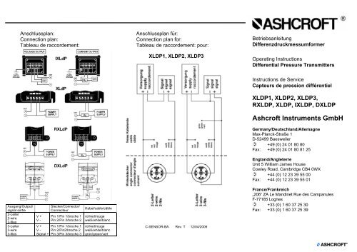
Anschlussplan:<br />
Connection plan:<br />
Tableau <strong>de</strong> raccor<strong>de</strong>ment:<br />
Anschlussplan für:<br />
Connection plan for:<br />
Tableau <strong>de</strong> raccor<strong>de</strong>ment: pour:<br />
XLDP1, XLDP2, XLDP3<br />
Betriebsanleitung<br />
Differenzdruckmessumformer<br />
Operating <strong>Instruction</strong>s<br />
Differential Pressure Transmitters<br />
<strong>Instruction</strong>s <strong>de</strong> Service<br />
Capteurs <strong>de</strong> pression différentiel<br />
XLDP1, XLDP2, XLDP3,<br />
RXLDP, XLDP, IXLDP, DXLDP<br />
<strong>Ashcroft</strong> <strong>Instruments</strong> <strong>GmbH</strong><br />
Germany/Deutschland/Allemagne<br />
Max-Planck-Straße 1<br />
D-52499 Baesweiler<br />
+49 (0) 24 01 80 80<br />
Fax: +49 (0) 24 01 80 81 25<br />
England/Angleterre<br />
Unit 5 William James House<br />
Cowley Road, Cambridge CB4 0WX<br />
+44 (0) 12 23 39 55 00<br />
Fax: +44 (0) 12 23 39 55 01<br />
Ausgang/Output/<br />
signal sortie<br />
2-Leiter<br />
2-wire<br />
2-files<br />
3-Leiter<br />
3-wire<br />
3-files<br />
V +<br />
V -<br />
V +<br />
V -<br />
Signal +<br />
Stecker/Connector/<br />
Connecteur<br />
Pin 1/Pin 1/broche 1<br />
Pin 2/Pin 2/broche 2<br />
Pin 1/Pin 1/broche 1<br />
Pin 2/Pin2/broche 2<br />
Pin 3/Pin 3/broche 3<br />
Kabel/cable/câble<br />
rot/red/rouge<br />
weiß/white/blanc<br />
rot/red/rouge<br />
weiß/white/blanc<br />
grün/green/vert<br />
C-SENSOR-BA Rev. T 12/04/2006<br />
France/Frankreich<br />
„206“ ZA Le Mandinet Rue <strong>de</strong>s Campanules<br />
F-77185 Lognes<br />
+33 (0) 1 60 37 25 30<br />
Fax: +33 (0) 1 60 37 25 39
1. Montagebedingungen<br />
- Zul. Umgebungstemperatur und Medientemperatur: -30 .. .80 °C für<br />
XLDP1uns IXLDP, an<strong>de</strong>re -20 ... 70 °C.<br />
- Nur für saubere trockene Luft und an<strong>de</strong>re nicht korrosive und nicht<br />
konduktive Gase.<br />
- Die angegebene Schutzart wird bei montiertem Steckverbin<strong>de</strong>r erreicht.<br />
Die Verwendung eines innenbelüfteten Kabels ist von Vorteil.<br />
- Die Einbaulage ist beliebig, eventuell Nullpunkt nachstellen.<br />
2. Montage<br />
- Druckanschlüsse während <strong>de</strong>r Montage gegen Verschmutzung<br />
schützen.<br />
- Abdichtung:<br />
- Geeignete Dichtmittel o<strong>de</strong>r Schläuche verwen<strong>de</strong>n, NPT- o<strong>de</strong>r Innengewin<strong>de</strong><br />
nach anwendungstechnischen Normen abdichten.<br />
Achtung !<br />
- Elektrostatische Entladungen vermei<strong>de</strong>n. Gehäuse er<strong>de</strong>n.<br />
- Druckmessumformer nur gemäß Anschlusstabelle bzw. Typenschild<br />
anschließen.<br />
- Keine Gegenstän<strong>de</strong> in die Druckkanalbohrung einführen.<br />
- Messbereich bzw. zulässigen Überdruck nicht überschreiten.<br />
Angaben in bar Prüfdruck Einseitige Überlast statisch maximal<br />
XLDP1 1,0 3,5 7,0<br />
XLDP2 0,7 1,7 1,7<br />
XLDP3 0,35 1,7 1,7<br />
IXLDP 1,0 3,5 7<br />
XLDP 0,7 1,7 1,7<br />
RXLDP 0,35 1,7 1,7<br />
DXLDP 0,7 1,7 1,7<br />
- Keinen Druckstrahl in das Gerät richten.<br />
3. Elektrischer Anschluss<br />
- Zulässige Speisespannung: 12..36 VDC (13 ...36 VDC bei XLDP2,<br />
XLDP für 4-20 mA), o<strong>de</strong>r Angaben für eigensichere Kreise beachten.<br />
- Anschluss gemäß Anschlusstabelle bzw. laut Typenschild-Angaben.<br />
4. Inbetriebnahme<br />
- Auch in Druckspitzen <strong>de</strong>n zulässigen Überdruck nicht überschreiten.<br />
- Bei extremen Bedingungen (Wasserhammer) Schutzelemente einbauen<br />
(z. B. Dämpfungselemente, Prallplatten).<br />
5. Abgleich<br />
- Der Druckmessumformer ist werksseitig abgeglichen (kalibriert).<br />
- Nullpunkt und Verstärkung können über Potentiometer nachgestellt<br />
wer<strong>de</strong>n. Das Nullpunktpotentiometer ist mit einer Markierung versehen.<br />
6. Wartung/Störung<br />
- Der Druckmessumformer ist wartungsfrei.<br />
- Im Störungsfall Verdrahtung, Spannungsversorgung und Einbau überprüfen.<br />
- Bei nicht behebbaren Störungen wen<strong>de</strong>n Sie sich bitte an unsere Nie<strong>de</strong>rlassungen<br />
und Vertretungen, die Ihnen mit Beratung und Service<br />
zur Verfügung stehen.<br />
Technische Än<strong>de</strong>rungen vorbehalten !<br />
1. Installation requirements<br />
- Ambient temperature and process temperature : -30 ... 80 °C for<br />
XLDP1and IXLDP, others -20 … 70 °C<br />
- Only for clean and dry air, and other non-corrosive and non-conductive<br />
gases.<br />
- The stated protection <strong>de</strong>grees is achieved with connector completely<br />
mounted.<br />
- Mounting position: effect negligeable (if necessary only reset zero)<br />
2. Mounting<br />
- Protect pressure ports against dirt during installation.<br />
- Sealing:<br />
- Use suitable sealants or tubes, seal NPT or female threads according<br />
existing standards.<br />
Attention !<br />
- Avoid electrostatic discharge. Earth case.<br />
- Connect wirings according connection table respectively pressure<br />
transmitter-label.<br />
- Do not insert objects into the pressure bore.<br />
- Do not exceed range or admissible overpressure.<br />
Value in bar Proof Single si<strong>de</strong>d load Max. Static load<br />
XLDP1 1,0 3,5 7,0<br />
XLDP2 0,7 1,7 1,7<br />
XLDP3 0,35 1,7 1,7<br />
IXLDP 1,0 3,5 7<br />
XLDP 0,7 1,7 1,7<br />
RXLDP 0,35 1,7 1,7<br />
DXLDP 0,7 1,7 1,7<br />
- Do not aim pressurized jets into the instrument.<br />
3. Electrical connection<br />
- Supply voltage: 12 ... 30 VDC (13 ... 36 VDC for XLDP2 and XLDP at 4-<br />
20 mA) or note ratings for intrinsically safe circuits.<br />
- Wiring according wiring table respectively pressure transmitter-label.<br />
4. Operation<br />
- Even in pressure peaks, never exceed the overpressure limit.<br />
- Take suitable precaution (e.g. pressure snubbers) un<strong>de</strong>r extreme conditions.<br />
5. Adjustment<br />
- The pressure transmitter is factory calibrated.<br />
- Zero and span can be adjust by potentiometers. The zero potentiometer<br />
is marked.<br />
6. Maintenance or <strong>de</strong>fault<br />
- The pressure transmitter is free of maintenance.<br />
- In case of any <strong>de</strong>fault check wiring, power supply and mounting.<br />
- If the <strong>de</strong>fault is not on wiring or mounting apply for assistance from<br />
ourselves or our agents. We will assist you with advice and <strong>service</strong>.<br />
Modification reserved !<br />
1. Conditions <strong>de</strong> montage<br />
- Température ambiante et process: -30 ... 80 °C pour XLDP1 et IXLDP,<br />
autres -20 ... 70 °C<br />
- Uniquement pour ais sec et propre et autres gazes non corrosifs et non<br />
conductifs.<br />
- Les <strong>de</strong>grés <strong>de</strong> protection sont atteints lorsque les connexions sont<br />
complètement installées.<br />
- Position <strong>de</strong> montage: indifférente (ci nécessaire faire la remise à zéro)<br />
2. Montage<br />
- Protéger les raccor<strong>de</strong>ments <strong>de</strong> pression contre l’encrassement pendant<br />
la montage<br />
- Etanchéité:<br />
- Utiliser joints ou tubes adapté, pour raccords NPT ou femelle suivant<br />
les normes en vigueur.<br />
Attention !<br />
- Eviter les décharges électrostatiques. Prise <strong>de</strong> terre.<br />
- Raccor<strong>de</strong>r le capteur suivant le tableau ci-contre.<br />
- Ne rien introduire dans l’orifice <strong>de</strong> passage <strong>de</strong> la pression.<br />
- Ne pas dépasser échelle mesure ou la pression maximum admissible.<br />
Pression d’une<br />
Valeurs en bar Pression max. seul coté Pression statique max.<br />
XLDP1 1,0 3,5 7,0<br />
XLDP2 0,7 1,7 1,7<br />
XLDP3 0,35 1,7 1,7<br />
IXLDP 1,0 3,5 7<br />
XLDP 0,7 1,7 1,7<br />
RXLDP 0,35 1,7 1,7<br />
DXLDP 0,7 1,7 1,7<br />
- Ne pas diriger <strong>de</strong> jets <strong>de</strong> pression dans l´instrument.<br />
3. Raccor<strong>de</strong>ment électrique<br />
- Tension d’alimentation: 12 .. .30 VCC (13 ... 36 VCC pour XLDP2 et<br />
XLDP en 4-20 mA), attention au besoins spécifiques pour sécurité intrinsèque.<br />
- Raccor<strong>de</strong>ment suivant le tableau ci - contre et les autocollants.<br />
4. Mise en <strong>service</strong><br />
- Ne jamais dépasser la surpression admissible du capteur.<br />
- Prendre les précaution nécessaires (par ex. limiteurs <strong>de</strong> pression dans<br />
cas <strong>de</strong> conditions d’utilisation extrêmes.<br />
5. Etalonnage<br />
- Le capteur est étalonné en usine.<br />
- Le zéro et la plage peuvent être réglés par <strong>de</strong>s potentiomètres. Le<br />
potentiomètre du zéro est indiqué.<br />
6. Entretien/Défectuosités<br />
- Le capteur est exempt d’entretien.<br />
- En cas d’anomalies, vérifier les fils, alimentation et la montage.<br />
- Si l’anomalie ne se situe pas au niveau <strong>de</strong>s fil ou du montage contacter<br />
nous ou l’un <strong>de</strong> nos agents. Nous vous conseillerons et vous dirigerons<br />
vers le <strong>service</strong> après-vente si nécessaire<br />
Sous réserve <strong>de</strong> modifications !