Serie UTBS - Soler & Palau Sistemas de Ventilación, SLU
Serie UTBS - Soler & Palau Sistemas de Ventilación, SLU
Serie UTBS - Soler & Palau Sistemas de Ventilación, SLU

Create successful ePaper yourself
Turn your PDF publications into a flip-book with our unique Google optimized e-Paper software.
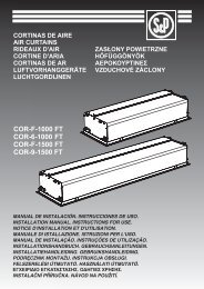
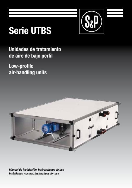
<strong>Serie</strong> <strong>UTBS</strong><br />
Unida<strong>de</strong>s <strong>de</strong> tratamiento<br />
<strong>de</strong> aire <strong>de</strong> bajo perfil<br />
Low-profile<br />
air-handling units<br />
Manual <strong>de</strong> instalación. Instrucciones <strong>de</strong> uso<br />
Installation manual. Instructions for use<br />
1
ESPAÑOL<br />
ESPAÑOL<br />
INDICE<br />
1. GENERALIDADES .................................................................3<br />
2. NORMAS DE SEGURIDAD Y MARCADO “CE” .................................................3<br />
3. NORMAS GENERALES .................................................................3<br />
4. ETIQUETADO DE LA UNIDAD ...............................................................4<br />
5. MANIPULACIÓN .................................................................5<br />
6. INSTALACIÓN .................................................................5<br />
6.1. GENERALIDADES ..............................................................5<br />
6.2. IDENTIFICACIÓN DE PARTES DEL EQUIPO ..........................................6<br />
6.3. LUGAR DE EMPLAZAMIENTO ....................................................6<br />
6.4. ESPACIO PARA MANTENIMIENTO .................................................6<br />
6.5. ENSAMBLAJE DE MÓDULOS .....................................................8<br />
6.5.1. UNIÓN DE TEJADILLOS ................................................8<br />
6.5.2. ENSAMBLAJE DE JUNTAS FLEXIBLES ....................................9<br />
6.5.3. ENSAMBLAJE DE UNIDADES EN PARALELO ...............................9<br />
6.6. CONEXIÓN ELÉCTRICA DEL EQUIPO .............................................10<br />
6.6.1. CONEXIÓN DE LOS MOTORES .........................................11<br />
6.6.2. CONEXIÓN DE LA BATERÍA ELÉCTRICA ..................................11<br />
6.7. CONEXIÓN DE SENSORES DE PRESIÓN ..........................................16<br />
6.7.1. ENSUCIAMIENTO DE FILTROS ..........................................16<br />
6.7.2. CONTROL EN VENTILADORES .................................................16<br />
6.7.2.1. CONEXIONADO DEL EQUIPO A PRESIÓN O CAUDAL CONSTANTE ...........16<br />
6.7.2.2. CONFIGURACIÓN DEL TRANSMISOR DE PRESIÓN DIFERENCIAL<br />
(TDP-S Y TDP-D) ..................................................18<br />
6.7.2.2.1. MODELO TDP-S ..........................................18<br />
6.7.2.2.2. MODELO TDP-D ..........................................19<br />
6.7.2.2.3. CALIBRACIÓN DEL TRANSMISOR DE PRESIÓN (TDP-S Y TDP-D) ..21<br />
6.7.2.3. CONFIGURACIÓN DEL VARIADOR DE FRECUENCIA .......................21<br />
6.7.2.3.1. AJUSTE DEL PUNTO DE TRABAJO ...........................21<br />
6.7.2.3.2. FUNCIONAMIENTO Y FALLOS ...............................22<br />
6.7.2.3.3. RECONFIGURACIÓN DEL VARIADOR DE FRECUENCIA ...........23<br />
6.8. CONEXIÓN DEL EQUIPO A LA RED HIDRÁULICA ....................................25<br />
6.9. CONEXIÓN DEL EQUIPO A LA RED DE CONDUCTOS ................................26<br />
6.10. RED DE DESAGÜE ...........................................................26<br />
6.11. INSTALACIÓN DE CAJAS CON COMPUERTAS .....................................27<br />
7. PROCEDIMIENTO DE PUESTA EN MARCHA .................................................27<br />
8. OPERACIONES DE EMERGENCIA .........................................................28<br />
9. MANTENIMIENTO PREVENTIVO . ..........................................................29<br />
9.1. BATERÍAS DE INTERCAMBIO TÉRMICO ...........................................29<br />
9.2. RED DE DESAGÜE ............................................................29<br />
9.3. MOTORES ................................................................29<br />
9.4. VENTILADORES ..............................................................30<br />
9.5. FILTROS ................................................................30<br />
9.5.1. SUSTITUCIÓN DE FILTRO EN EQUIPO PRINCIPAL<br />
Y RECUPERADOR PARALELO Y DE DOBLE ALTURA. .......................30<br />
9.5.2. SUSTITUCIÓN DE FILTROS EN RECUPERADORES EN LÍNEA .................31<br />
9.6. BATERÍAS ................................................................31<br />
9.7. COMPUERTAS ...............................................................31<br />
9.8. SILENCIADOR . ...............................................................32<br />
9.8.1. MÓDULO DE MEZCLAS ...............................................32<br />
9.8.2. CAJA DE MEZCLA 2 VÍAS CON BANCADA Y TEJADILLO .....................33<br />
9.9. HUMECTADOR ...............................................................33<br />
9.10. RECUPERADOR .............................................................34<br />
10. RECICLAJE ................................................................34<br />
2
1. Generalida<strong>de</strong>s<br />
• Le agra<strong>de</strong>cemos la confianza que ha <strong>de</strong>positado en nosotros mediante la compra <strong>de</strong> este<br />
aparato. Usted ha adquirido un producto <strong>de</strong> calidad que ha sido totalmente fabricado según<br />
las reglas técnicas <strong>de</strong> seguridad reconocidas y conformes a las normas <strong>de</strong> la CE.<br />
• Lea atentamente el contenido <strong>de</strong>l presente libro <strong>de</strong> instrucciones, pues contiene indicaciones<br />
importantes para su seguridad durante la instalación, el uso y el mantenimiento <strong>de</strong> este<br />
producto. Consérvelo para consultas posteriores.<br />
• Rogamos compruebe el perfecto estado <strong>de</strong>l aparato al <strong>de</strong>sembalarlo, ya que cualquier<br />
<strong>de</strong>fecto <strong>de</strong> origen que presente está amparado por la garantía S&P.<br />
• El personal responsable <strong>de</strong>l montaje, <strong>de</strong> la puesta en marcha y <strong>de</strong>l mantenimiento, <strong>de</strong>be<br />
leer estas instrucciones <strong>de</strong> uso y familiarizarse con ellas antes <strong>de</strong> empezar.<br />
ESPAÑOL<br />
2. NORMAS DE SEGURIDAD Y MARCADO “CE”<br />
• Los técnicos <strong>de</strong> S&P están firmemente comprometidos con la investigación y <strong>de</strong>sarrollo <strong>de</strong><br />
productos cada vez más eficientes y que cumplan con las normas <strong>de</strong> seguridad en vigor.<br />
• Las normas y recomendaciones que se indican a continuación, reflejan las normas vigentes,<br />
preferentemente en materia <strong>de</strong> seguridad y por lo tanto se basan principalmente en<br />
el cumplimiento <strong>de</strong> las normas <strong>de</strong> carácter general. Por consiguiente, recomendamos a<br />
todas las personas expuestas a riesgos que se atengan escrupulosamente a las normas<br />
<strong>de</strong> prevención <strong>de</strong> acci<strong>de</strong>ntes en vigor en su país<br />
• S&P queda exento <strong>de</strong> cualquier responsabilidad por eventuales daños causados a personas<br />
y objetos <strong>de</strong>rivados <strong>de</strong> la falta <strong>de</strong> cumplimiento <strong>de</strong> las normas <strong>de</strong> seguridad, así como<br />
<strong>de</strong> posibles modificaciones en el producto. El sello CE y la correspondiente <strong>de</strong>claración <strong>de</strong><br />
conformidad, atestiguan la conformidad con las normas comunitarias aplicables.<br />
3. NORMAS GENERALES<br />
• Se ha realizado el análisis <strong>de</strong> los riesgos <strong>de</strong>l producto como está previsto en la Directiva<br />
<strong>de</strong> Máquinas. Este manual contiene la información <strong>de</strong>stinada a todo el personal expuesto,<br />
con el fin <strong>de</strong> prevenir posibles daños a personas y/o objetos a causa <strong>de</strong> una <strong>de</strong>fectuosa<br />
manipulación o mantenimiento. Todas las intervenciones <strong>de</strong> mantenimiento (correctivo y<br />
preventivo) <strong>de</strong>ben ser realizadas con la máquina parada y la corriente eléctrica <strong>de</strong>sconectada.<br />
• Para evitar el peligro <strong>de</strong> posible arranque acci<strong>de</strong>ntal, ponga carteles <strong>de</strong> advertencia en el<br />
cuadro eléctrico central y en la consola <strong>de</strong> control con el siguiente mensaje:<br />
”Atención: control <strong>de</strong>sconectado para operaciones <strong>de</strong> mantenimiento”<br />
• Antes <strong>de</strong> conectar el cable <strong>de</strong> alimentación eléctrica a los motores, verifique que la tensión<br />
<strong>de</strong> línea correspon<strong>de</strong> a la indicada en la placa <strong>de</strong> características <strong>de</strong> la unidad.<br />
• Verifique periódicamente las etiquetas <strong>de</strong>l producto. Si con el paso <strong>de</strong>l tiempo son ilegibles,<br />
<strong>de</strong>ben ser sustituidas.<br />
3
4. ETIQUETADO DE LA UNIDAD<br />
ESPAÑOL<br />
• La unidad está provista <strong>de</strong> diversos pictogramas <strong>de</strong> señalización que no <strong>de</strong>ben ser eliminados.<br />
Las señales se divi<strong>de</strong>n en:<br />
Pictograma / Etiqueta<br />
Significado<br />
Señalización <strong>de</strong>l registro <strong>de</strong> acceso a<br />
los ventiladores. Indica la obligatoriedad<br />
<strong>de</strong> <strong>de</strong>sconectar el equipo y esperar,<br />
pues hay partes en movimiento y<br />
existe el peligro <strong>de</strong> enganchar alguna<br />
parte <strong>de</strong>l cuerpo.<br />
Indicación <strong>de</strong>l sentido <strong>de</strong>l aire en la<br />
unidad.<br />
Indicación <strong>de</strong> entrada y salida <strong>de</strong>l fluido<br />
<strong>de</strong>l intercambiador térmico <strong>de</strong> agua<br />
fría.<br />
Indicación <strong>de</strong> entrada y salida <strong>de</strong>l fluido<br />
<strong>de</strong>l intercambiador térmico <strong>de</strong> agua<br />
caliente.<br />
Placa <strong>de</strong> características <strong>de</strong> la unidad.<br />
En ella se indica<br />
- Mo<strong>de</strong>lo<br />
- Código<br />
- Número <strong>de</strong> serie<br />
- Año <strong>de</strong> fabricación<br />
- Potencia útil <strong>de</strong> motores instalados<br />
- Intensidad máxima absoluta <strong>de</strong>l<br />
motor (A)<br />
- Potencia batería eléctrica instalada.<br />
- Alimentación<br />
4
5. MANIPULACIÓN<br />
• A la recepción <strong>de</strong>l equipo, se <strong>de</strong>sembalará la unidad comprobando la integridad <strong>de</strong> ésta,<br />
cualquier <strong>de</strong>sperfecto pue<strong>de</strong> ser indicativo <strong>de</strong> un daño en el equipo. Se repasará y comprobará<br />
que no falte ningún elemento.<br />
• Si la unidad presenta algún daño o el envío no es completo, anotar las inci<strong>de</strong>ncias en el<br />
albarán <strong>de</strong> entrega y enviar una reclamación a la compañía que realizó el envío. Asimismo<br />
hacer constar cualquier inci<strong>de</strong>ncia a S&P.<br />
• El climatizador se suministra dividido en módulos. El traslado <strong>de</strong> cada uno <strong>de</strong> los módulos<br />
hasta su lugar <strong>de</strong> implantación <strong>de</strong>finitiva solo podrá realizarse en la posición <strong>de</strong> montaje<br />
salvo autorización expresa <strong>de</strong>l fabricante.<br />
• Los aparatos se <strong>de</strong>berán transportar con correas <strong>de</strong> elevación. El equipo posee unas cantoneras<br />
agujereadas para su carga y <strong>de</strong>scarga.<br />
ESPAÑOL<br />
6. INSTALACIÓN<br />
6.1. GENERALIDADES<br />
• El empleado encargado <strong>de</strong> la recepción <strong>de</strong>l equipo <strong>de</strong>berá asegurarse que las características<br />
<strong>de</strong>l suministro eléctrico disponible están <strong>de</strong> acuerdo con los datos eléctricos que hay<br />
en la placa <strong>de</strong> características <strong>de</strong> la unidad.<br />
• Antes <strong>de</strong> implantar el equipo en su lugar <strong>de</strong>finitivo, se comprobará que el lugar don<strong>de</strong> se<br />
va a ubicar el equipo es lo suficientemente resistente como para po<strong>de</strong>r soportar el peso <strong>de</strong><br />
éste.<br />
• No se instalarán estos equipos, bajo ningún concepto, en entornos inflamables o explosivos,<br />
en entornos cargados <strong>de</strong> vapores <strong>de</strong> aceite, <strong>de</strong> aire salino o corrosivos.<br />
• La instalación <strong>de</strong> los equipos pue<strong>de</strong> ser peligrosa, <strong>de</strong>bido al material usado, a las presiones<br />
en el sistema y a los componentes eléctricos. Es por ello que sólo personal <strong>de</strong> servicio<br />
entrenado y cualificado <strong>de</strong>be instalar, servir o reparar los equipos.<br />
• Se tendrá la precaución, cuando se hagan operaciones en el interior <strong>de</strong>l equipo, <strong>de</strong> interrumpir<br />
la corriente eléctrica en el seccionador principal, para impedir los posibles acci<strong>de</strong>ntes<br />
con las partes móviles <strong>de</strong>l equipo que puedan ponerse en marcha imprevisiblemente,<br />
así como para impedir un contacto directo o indirecto con cualquier parte activa.<br />
• En la instalación <strong>de</strong>l equipo se <strong>de</strong>berá nivelar para un buen ajuste <strong>de</strong> los diferentes módulos,<br />
un perfecto evacuado <strong>de</strong> con<strong>de</strong>nsados y una buena apertura <strong>de</strong> los registros.<br />
• Para comprobar el perfecto estado <strong>de</strong>l ventilador se revisará el centrado <strong>de</strong>l aro <strong>de</strong> aspiración<br />
haciendo girar la turbina a mano.<br />
5
6.2. IDENTIFICACIÓN DE PARTES DEL EQUIPO<br />
ESPAÑOL<br />
El módulo principal pue<strong>de</strong> estar compuesto por tres secciones diferenciadas: filtro, baterías y<br />
ventiladores, pudiendo no estar alguna <strong>de</strong> las dos primeras. En la figura siguiente se i<strong>de</strong>ntifican<br />
los componentes principales <strong>de</strong>l módulo principal.<br />
6.3. LUGAR DE EMPLAZAMIENTO<br />
• Evitar la instalación <strong>de</strong>l aparato en zonas próximas a fuentes <strong>de</strong> calor y zonas húmedas<br />
dón<strong>de</strong> la unidad pueda entrar en contacto con el agua.<br />
• Se aconseja emplazar la unidad en una ubicación dón<strong>de</strong> la instalación sea <strong>de</strong> fácil acceso.<br />
Prever un espacio suficiente para el mantenimiento, el conexionado y la evacuación <strong>de</strong><br />
con<strong>de</strong>nsados.<br />
6.4. ESPACIO PARA MANTENIMIENTO<br />
• El instalador <strong>de</strong>be prever unos espacios libres <strong>de</strong> obstrucción y po<strong>de</strong>r acce<strong>de</strong>r libremente<br />
al aparato para su mantenimiento. El espacio requerido <strong>de</strong>pen<strong>de</strong>rá <strong>de</strong>l lado <strong>de</strong> la unidad<br />
dón<strong>de</strong> se haga la extracción. El equipo está provisto <strong>de</strong> unos registros laterales para po<strong>de</strong>r<br />
acce<strong>de</strong>r a los filtros o a los ventiladores. Para extraer las baterías se <strong>de</strong>be sacar el panel<br />
lateral. Tanto los filtros como los ventiladores se pue<strong>de</strong>n extraer por cualquier lado <strong>de</strong> la<br />
unidad.<br />
6
ESPAÑOL<br />
Mo<strong>de</strong>lo A (mm) B (mm)<br />
<strong>UTBS</strong>-2 750 360<br />
<strong>UTBS</strong>-3 1100 410<br />
<strong>UTBS</strong>-5 1500 410<br />
<strong>UTBS</strong>-8 1900 500<br />
• Para el montaje en techo y suelo, se <strong>de</strong>berá suspen<strong>de</strong>r <strong>de</strong> las cuatro escuadras existentes<br />
en cada módulo como sigue:<br />
MONTAJE EN TECHO<br />
MONTAJE EN SUELO<br />
ATENCIÓN! Debido a la longitud y el peso <strong>de</strong> los aparatos, se <strong>de</strong>berá suspen<strong>de</strong>r<br />
cada módulo por separado.<br />
7
Ningún obstáculo <strong>de</strong>berá impedir o reducir el paso <strong>de</strong> aire en aspiración.<br />
POSICIÓN MONTAJE<br />
ESPAÑOL<br />
6.5. ENSAMBLAJE DE MÓDULOS<br />
Los bastidores <strong>de</strong> los módulos disponen <strong>de</strong> escuadras en las cuatro esquinas cuya función<br />
es la sujeción <strong>de</strong>l equipo al techo y la sujeción <strong>de</strong> diferentes módulos entre si. Si el equipo<br />
está formado por diferentes módulos se suministrará un kit <strong>de</strong> unión compuesto por 4 juegos<br />
<strong>de</strong> tornillos, aran<strong>de</strong>las, tuercas y junta <strong>de</strong> estanqueidad.<br />
6.5.1. UNIÓN DE TEJADILLOS<br />
Si ha pedido un climatizador para ir a la intemperie, el equipo llevará incorporado un tejadillo<br />
anti-lluvia. En caso que el climatizador esté formado por uno o más módulos, la unión <strong>de</strong> los<br />
tejadillos se <strong>de</strong>berá realizar poniendo masilla en las uniones , cómo indica la figura:<br />
8
6.5.2. ENSAMBLAJE DE JUNTAS FLEXIBLES<br />
Si ha pedido juntas flexibles en las terminaciones <strong>de</strong> las unida<strong>de</strong>s, se le suministrarán por<br />
separado.<br />
ESPAÑOL<br />
6.5.3. ENSAMBLAJE DE UNIDADES EN PARALELO<br />
Cuándo se hayan pedido equipos para instalar en paralelo, en el caso <strong>de</strong> tener módulo recuperador<br />
o módulo free-cooling, el equipo vendrá provisto <strong>de</strong> escuadras para unir los módulos.<br />
Para fijar dichas escuadras se <strong>de</strong>berá acce<strong>de</strong>r al equipo por el interior:<br />
- Situar la escuadra sobre el perfil <strong>de</strong> aluminio y atornillar con dos tornillos autotaladrantes<br />
(1)<br />
- Colocar burlete (2)<br />
- Proce<strong>de</strong>r a la unión <strong>de</strong> los módulos fijando las dos escuadras mediante un tornillo<br />
M8, aran<strong>de</strong>las y una tuerca (3)<br />
9
Ejemplo <strong>de</strong> unión <strong>de</strong> módulos en paralelo:<br />
ESPAÑOL<br />
6.6. CONEXIÓN ELÉCTRICA DEL EQUIPO<br />
• La instalación <strong>de</strong>be ser realizada por personal calificado.<br />
• Se instalarán cables cuya sección cumpla las directivas actuales e impidan un calentamiento<br />
<strong>de</strong> éstos y una caída <strong>de</strong> tensión superior a la permitida. Se cumplirá la normativa vigente<br />
y en todo momento se seguirán los criterios <strong>de</strong>l proyectista.<br />
• Antes <strong>de</strong> realizar la conexión <strong>de</strong> los cables, se comprobará que la instalación eléctrica esté<br />
<strong>de</strong>sconectada y que no haya tensión entre los cables.<br />
• Una vez instalado, el aparato <strong>de</strong>be cumplir con las Directivas siguientes:<br />
- Directiva <strong>de</strong> Baja Tension 2006/95/CE<br />
- Directiva <strong>de</strong> Máquinas 2006/42/CE<br />
- Directiva <strong>de</strong> Compatibilidad Electromegnética 2004/108/CE<br />
• Realizadas estas operaciones hay que verificar el apriete <strong>de</strong> todas las conexiones eléctricas<br />
(un cable mal apretado pue<strong>de</strong> ocasionar daños irreparables).<br />
• Verificar que la puesta a tierra se ha efectuado correctamente y que las protecciones térmicas<br />
y <strong>de</strong> sobre-intensidad han sido reguladas conforme a los valores establecidos en la<br />
placa <strong>de</strong> características.<br />
• Como medida <strong>de</strong> seguridad si el ventilador se quedara sin tensión se <strong>de</strong>berán realizar los<br />
enclavamientos necesarios para que todos los <strong>de</strong>más elementos eléctricos que<strong>de</strong>n sin<br />
tensión.<br />
10
6.6.1. CONEXIÓN DE LOS MOTORES<br />
ESPAÑOL<br />
• Para realizar el conexionado <strong>de</strong> los motores:<br />
- En los equipos la caja <strong>de</strong> conexiones <strong>de</strong> los motores está orientada hacia el lado<br />
<strong>de</strong>l registro <strong>de</strong> inspección para facilitar su acceso.<br />
• Pasar la manguera por los pasacables instalados en la unidad:<br />
6.6.2. CONEXIÓN DE LA BATERÍA ELÉCTRICA<br />
• Utilizar la batería eléctrica únicamente para recalentar el aire limpio. El ensuciamiento <strong>de</strong> las<br />
resistencias eléctricas aumenta el riesgo <strong>de</strong> incendio. Se recomienda la utilización <strong>de</strong> un<br />
filtro <strong>de</strong> aire encima <strong>de</strong> la batería.<br />
• La conexión eléctrica <strong>de</strong>berá prever un dispositivo <strong>de</strong> control <strong>de</strong>l caudal <strong>de</strong> aire. La batería<br />
<strong>de</strong>berá ponerse en marcha cuando se alcance el caudal <strong>de</strong> aire mínimo o bien cuando la<br />
velocidad <strong>de</strong>l aire <strong>de</strong>ntro <strong>de</strong> la batería sea superior a 1,5m/s.<br />
• La instalación eléctrica no <strong>de</strong>be permitir que se pueda poner en marcha la batería si el ventilador<br />
está parado. La batería eléctrica <strong>de</strong>be ponerse en marcha <strong>de</strong>spués o bien al mismo<br />
tiempo que el ventilador.<br />
• La instalación eléctrica no <strong>de</strong>be permitir que se pueda parar el ventilador cuando la batería<br />
esté en funcionamiento. El ventilador <strong>de</strong>be permanecer parado <strong>de</strong>spués <strong>de</strong>l paro y el enfriamiento<br />
<strong>de</strong> la batería.<br />
• No tocar la batería eléctrica cuando esté en funcionamiento.<br />
• En caso <strong>de</strong> que uno <strong>de</strong> los dispositivos <strong>de</strong> protección eléctrica <strong>de</strong> la instalación se accionara,<br />
<strong>de</strong>senchufar el aparato y verificar la instalación antes <strong>de</strong> ponerla en marcha <strong>de</strong> nuevo.<br />
11
En el esquema adjunto se muestra como conectar las resistencias <strong>de</strong> la batería eléctrica:<br />
Conexionado electrico BE-2 15 kw 1 etapa catalogo<br />
ESPAÑOL<br />
Conexionado electrico BE-2 7,5 kw 2 etapas catalogo<br />
12
Conexionado electrico BE-3 24 kw 1 etapa catalogo<br />
ESPAÑOL<br />
Conexionado electrico BE-3 24 kw 2 etapas catalogo<br />
13
Conexionado electrico BE-5 18 kw 2 etapas catalogo<br />
ESPAÑOL<br />
Conexionado electrico BE-5 12 kw 3 etapas catalogo<br />
14
Conexionado electrico BE-8 22,5 kw 2 etapas catalogo<br />
ESPAÑOL<br />
Conexionado electrico BE-8 15 kw 3 etapas catalogo<br />
15
6.7. CONEXIÓN DE SENSORES DE PRESIÓN<br />
ESPAÑOL<br />
6.7.1. ENSUCIAMIENTO DE FILTROS<br />
Para controlar el ensuciamiento <strong>de</strong> los filtros el equipo dispone <strong>de</strong> 2 tomas <strong>de</strong> presión a cada<br />
lado <strong>de</strong> los filtros con el fin <strong>de</strong> conectar un presostato. En el apartado 9.5. se muestra una<br />
tabla con los valores recomendados para la sustitución <strong>de</strong> los filtros.<br />
6.7.2. CONTROL EN VENTILADORES<br />
• El equipo dispone <strong>de</strong> 3 tomas <strong>de</strong> presión para controlar el ventilador a caudal constante o<br />
a presión constante. Para realizar un control a caudal constante es necesario introducir el<br />
valor “K” <strong>de</strong> la siguiente tabla:<br />
<strong>UTBS</strong>-2 K=69<br />
<strong>UTBS</strong>-3 K=84<br />
<strong>UTBS</strong>-5 K=84<br />
<strong>UTBS</strong>-8 K=104<br />
6.7.2.1 Conexionado <strong>de</strong>l equipo a presión o caudal constante<br />
16
ESPAÑOL<br />
• Comprobar que el interruptor “SW1” <strong>de</strong>l variador <strong>de</strong> frecuencia está en la posición SOURCE.<br />
ATENCIÓN: cuando se utilice un único variador <strong>de</strong> frecuencia para controlar<br />
dos motores los protectores térmicos se conectarán en serie.<br />
6.7.2.2 Configuración <strong>de</strong>l transmisor <strong>de</strong> presión diferencial<br />
(TDP-S y TDP-D)<br />
• Si se <strong>de</strong>sea configurar el equipo para realizar un control a presión constante pue<strong>de</strong>n emplearse<br />
los mo<strong>de</strong>los <strong>de</strong> transmisor <strong>de</strong> presión diferencial TDP-S y TDP-D. Si se <strong>de</strong>sea llevar<br />
a cabo un control a caudal constante únicamente se pue<strong>de</strong> utilizar el mo<strong>de</strong>lo TDP-D.<br />
El conexionado <strong>de</strong> los tubos <strong>de</strong> presión <strong>de</strong>pen<strong>de</strong>rá <strong>de</strong>l tipo <strong>de</strong> control requerido, tal y como<br />
se muestra en la siguiente figura<br />
17
ESPAÑOL<br />
Importante: el tubo <strong>de</strong> presión más alta tiene que conectarse al terminal “+” y el <strong>de</strong> presión<br />
más baja al “-“. En caso <strong>de</strong> no realizarse <strong>de</strong> esta manera la presión medida estará fuera <strong>de</strong><br />
rango y la pantalla <strong>de</strong>l transmisor parpa<strong>de</strong>ará.<br />
6.7.2.2.1 Mo<strong>de</strong>lo TDP-S<br />
18
Funcionamiento a presión constante<br />
• Situar el jumper <strong>de</strong> tipo señal <strong>de</strong> salida <strong>de</strong>l trasmisor (mA/V) en la posición <strong>de</strong> voltaje (configuración<br />
<strong>de</strong> fábrica).<br />
• Configurar el micro interruptor DIP tal y como se indica en las tablas siguientes. La selección<br />
<strong>de</strong>l rango <strong>de</strong> presión <strong>de</strong>seado se realiza mediante los interruptores DIP1, DIP2 y DIP3.<br />
Rango <strong>de</strong> presión (Pa) DIP 1 DIP 2 DIP 3<br />
-50...+50 1 1 1<br />
0...+100 0 1 1<br />
0...+150 1 0 1<br />
0...+300 0 0 1<br />
0...+500 1 1 0<br />
0...+1000 0 1 0<br />
0...+1600 1 0 0<br />
0...+2500 0 0 0<br />
ESPAÑOL<br />
Micro interruptor DIP 4/5/6 ON / OFF Observaciones<br />
DIP 4 - No utilizado<br />
DIP 5<br />
Seleccionar en función <strong>de</strong>l tiempo <strong>de</strong> amortiguación<br />
<strong>de</strong>seado: 0,4s (OFF) / 10s (ON)<br />
DIP 6 OFF Voltaje <strong>de</strong> salida mínimo 0V<br />
6.7.2.2.2 Mo<strong>de</strong>lo TDP-D<br />
19
Funcionamiento a presión constante<br />
ESPAÑOL<br />
• Situar el jumper <strong>de</strong> tipo señal <strong>de</strong> salida <strong>de</strong>l trasmisor (mA/V) en la posición <strong>de</strong> voltaje (configuración<br />
<strong>de</strong> fábrica).<br />
• Configurar el micro interruptor DIP tal y como se indica en la siguiente tabla:<br />
Micro interruptor DIP ON / OFF Observaciones<br />
DIP 1 - No utilizado<br />
DIP 2 - No utilizado<br />
DIP 3 - No utilizado<br />
DIP 4 OFF Modo presión (Pa)<br />
DIP 5<br />
Seleccionar en función <strong>de</strong>l tiempo <strong>de</strong><br />
amortiguación <strong>de</strong>seado: 0,4s (OFF) / 10s (ON)<br />
DIP 6 OFF Voltaje <strong>de</strong> salida mínimo 0V<br />
• Ajustar el rango <strong>de</strong> presión: para ello pulse el botón <strong>de</strong> “OK” y <strong>de</strong>splácese al rango <strong>de</strong>seado<br />
mediante los botones “” y “” . Finalmente vuelva a pulsar “OK” para guardar la configuración.<br />
Los rangos <strong>de</strong> presión seleccionables son los siguientes: -50...+50 Pa; 0...+100 Pa;<br />
0...+150 Pa; 0...+300 Pa; 0...+500 Pa; 0...+1000 Pa; 0...+1600 Pa; 0...+2500 Pa.<br />
Funcionamiento a caudal constante<br />
Disponible únicamente en el mo<strong>de</strong>lo TDP-D.<br />
En este modo <strong>de</strong> funcionamiento el transmisor <strong>de</strong> presión convierte la presión diferencial (∆P)<br />
a caudal (qv) mediante la siguiente ecuación:<br />
q v<br />
= k √∆ P<br />
• Situar el jumper <strong>de</strong> tipo señal <strong>de</strong> salida <strong>de</strong>l trasmisor (mA/V) en la posición <strong>de</strong> voltaje (configuración<br />
<strong>de</strong> fábrica).<br />
• Configurar el micro interruptor DIP tal y como se indica en la siguiente tabla:<br />
Micro interruptor DIP ON / OFF Observaciones<br />
DIP 1 - No utilizado<br />
DIP 2 - No utilizado<br />
DIP 3 - No utilizado<br />
DIP 4 ON Modo caudal<br />
DIP 5<br />
Seleccionar en función <strong>de</strong>l tiempo <strong>de</strong><br />
amortiguación <strong>de</strong>seado: 0,4s (OFF) / 10s (ON)<br />
DIP 6 OFF Voltaje <strong>de</strong> salida mínimo 0V<br />
20
• Ajustar el rango <strong>de</strong> caudal y el parámetro k: pulsando el botón “OK” se acce<strong>de</strong> en primer<br />
lugar a la selección <strong>de</strong>l rango <strong>de</strong> caudal. Pulsándolo nuevamente se va accediendo uno a uno<br />
a los distintos dígitos <strong>de</strong>l parámetro k, con la posibilidad <strong>de</strong> elegir o no un <strong>de</strong>cimal. Mediante<br />
los botones “” y “” se ajustan los valores <strong>de</strong>seados. Finalmente volviendo a pulsar “OK”<br />
se guarda la configuración y se sale <strong>de</strong>l menú <strong>de</strong> ajuste. Los rangos <strong>de</strong> caudal seleccionables<br />
son los siguientes: 100 m 3 /h; 300 m 3 /h; 500 m 3 /h; 1000 m 3 /h; 3000 m 3 /h; 5000 m 3 /h;<br />
9999 m 3 /h; 30 m 3 /h x 1000; 50 m 3 /h x 1000; 99,99 m 3 /h x 1000. Las unida<strong>de</strong>s m 3 /h pue<strong>de</strong>n<br />
reemplazarse por l/s.<br />
ESPAÑOL<br />
• Pegar la etiqueta adhesiva correspondiente a la unidad <strong>de</strong> medida empleada en el parámetro<br />
k ( m 3 /h, l/s, m 3 /h x 1000, l/s x 1000).<br />
6.7.2.2.3 Calibración <strong>de</strong>l transmisor <strong>de</strong> presión (TDP-S y TDP-D)<br />
Una vez realizado todo el conexionado se recomienda efectuar un calibrado a cero. Tras encen<strong>de</strong>r<br />
el equipo (se ilumina el LED ver<strong>de</strong>) espere unos instantes a que el transmisor alcance<br />
la temperatura <strong>de</strong> funcionamiento usual. A continuación pulse el botón <strong>de</strong> puesta a cero.<br />
El LED amarillo parpa<strong>de</strong>ará hasta que finalice el proceso <strong>de</strong> calibración. Para llevar a cabo<br />
correctamente la calibración la presión en los terminales + y – ha <strong>de</strong> ser la misma. Se recomienda<br />
que los tubos estén <strong>de</strong>sconectados.<br />
6.7.2.3 Configuración <strong>de</strong>l variador <strong>de</strong> frecuencia<br />
El variador <strong>de</strong> frecuencia viene pre-configurado por S&P para realizar un control a presión o<br />
caudal constante, y el único ajuste que es necesario realizar es configurar la frecuencia <strong>de</strong>l<br />
punto <strong>de</strong> trabajo <strong>de</strong>l equipo.<br />
6.7.2.3.1 Ajuste <strong>de</strong>l punto <strong>de</strong> trabajo<br />
El rango <strong>de</strong> frecuencias <strong>de</strong> funcionamiento está prefijado por <strong>de</strong>fecto entre 20Hz y 50Hz. En<br />
algunas situaciones el punto <strong>de</strong> trabajo requiere una frecuencia <strong>de</strong> salida superior a 50Hz, por<br />
lo que será necesario reconfigurar este parámetro. El reajuste es únicamente necesario<br />
si la frecuencia <strong>de</strong>l punto <strong>de</strong> trabajo es superior a 50Hz, no siéndolo cuando es inferior.<br />
Este dato pue<strong>de</strong> encontrarlo en la hoja <strong>de</strong> selección <strong>de</strong>l equipo y correspon<strong>de</strong> al punto<br />
<strong>de</strong> operación máximo <strong>de</strong>l sistema. Para ajustarlo proceda como se <strong>de</strong>talla a continuación.<br />
Para <strong>de</strong>splazarse entre los diferentes menús y entre los valores <strong>de</strong> un parámetro <strong>de</strong>ntro <strong>de</strong><br />
un menú girar la rueda. Para acce<strong>de</strong>r a un menú <strong>de</strong>terminado y para seleccionar el valor<br />
<strong>de</strong> un parámetro pulse “ENT”. Para retroce<strong>de</strong>r al menú anterior o salir <strong>de</strong> la selección <strong>de</strong> un<br />
parámetro pulse “ESC”.<br />
21
ESPAÑOL<br />
En primer lugar entre en modo programación. El variador dispone <strong>de</strong> dos modos <strong>de</strong> funcionamiento,<br />
RUN y PROGRAMACIÓN. Para pasar <strong>de</strong> uno a otro es necesario pulsar ESC durante<br />
dos segundos.<br />
• Pulse ESC durante dos segundos hasta que los leds indicadores <strong>de</strong> modo parpa<strong>de</strong>en<br />
simultáneamente.<br />
A continuación <strong>de</strong>sbloquee el variador:<br />
• Pulse “ENT” y gire la rueda hasta llegar al menú “SUP-“<br />
• Pulse “ENT” y gire la rueda hasta el parámetro “COd”<br />
• Pulse “ENT” y gire la rueda hasta que aparezca “1951”<br />
• Pulse “ENT” y gire la rueda hasta que aparezca “OFF”<br />
• Pulse “ENT” y vuelva al menú principal pulsando dos veces “ESC”<br />
Verifique si el valor <strong>de</strong>l parámetro “tFr” <strong>de</strong>l menú “drC” es igual o mayor que el valor <strong>de</strong> la<br />
frecuencia <strong>de</strong>l punto <strong>de</strong> trabajo <strong>de</strong>l equipo. De no ser así, modifique éste parámetro con un<br />
valor igual o superior al <strong>de</strong>l punto <strong>de</strong> trabajo <strong>de</strong>l equipo:<br />
• Pulse “ENT” y gire la rueda hasta llegar al menú “drC-“<br />
• Pulse “ENT” y gire la rueda hasta el parámetro “tFr”<br />
• Pulse “ENT” y gire la rueda hasta un valor igual o superior al <strong>de</strong> la frecuencia <strong>de</strong> trabajo <strong>de</strong>l<br />
equipo<br />
• Pulse “ENT” y vuelva al menú principal pulsando dos veces “ESC”<br />
A continuación introduzca el valor <strong>de</strong> la frecuencia <strong>de</strong>l punto <strong>de</strong> trabajo <strong>de</strong>l equipo en el parámetro<br />
“HSP” <strong>de</strong>l menú “Set”:<br />
• Gire la rueda hasta llegar al menú “Set-“<br />
• Pulse “ENT” y gire la rueda hasta el parámetro “HSP”<br />
• Pulse “ENT” y gire la rueda hasta introducir el valor <strong>de</strong> la frecuencia <strong>de</strong> trabajo <strong>de</strong>l<br />
equipo<br />
• Pulse “ENT” y salga <strong>de</strong>l menú <strong>de</strong> configuración pulsando tres veces “ESC”<br />
Por último vuelva a pulsar durante dos segundos “ESC” hasta que los 3 leds indicadores se<br />
iluminen <strong>de</strong> forma secuencial para volver al modo RUN (modo <strong>de</strong> funcionamiento automático<br />
<strong>de</strong>l variador <strong>de</strong> frecuencia).<br />
6.7.2.3.2 Funcionamiento y fallos<br />
Puesta en marcha <strong>de</strong>l equipo:<br />
El equipo se pone en marcha automáticamente a la puesta en tensión. La modificación <strong>de</strong>l<br />
valor <strong>de</strong> consigna se realiza mediante el parámetro rPI, accesible <strong>de</strong>s<strong>de</strong> los menús “rEF”,<br />
“Set” y submenú “-PI” <strong>de</strong>l menú “Fun”.<br />
22
Pasos a seguir en caso <strong>de</strong> fallo <strong>de</strong>l variador <strong>de</strong> frecuencia:<br />
Con el fin evitar posibles daños a personas, el rearme <strong>de</strong>l variador es manual. En caso <strong>de</strong> fallo<br />
se proce<strong>de</strong>rá como se <strong>de</strong>talla a continuación:<br />
• Desconectar el variador <strong>de</strong> la alimentación<br />
• Solucionar el problema<br />
• Volver a dar tensión al variador (el ventilador se pondrá en marcha automáticamente)<br />
6.7.2.3.3 Reconfiguración <strong>de</strong>l variador <strong>de</strong> frecuencia<br />
ESPAÑOL<br />
En caso <strong>de</strong> producirse una <strong>de</strong>sconfiguración por error <strong>de</strong>l variador <strong>de</strong> frecuencia, proceda<br />
como se <strong>de</strong>scribe a continuación.<br />
En primer lugar entre en modo programación. El variador dispone <strong>de</strong> dos modos <strong>de</strong> funcionamiento,<br />
RUN y PROGRAMACIÓN. Para pasar <strong>de</strong> uno a otro es necesario pulsar ESC durante<br />
dos segundos.<br />
• Pulse ESC durante dos segundos hasta que los leds indicadores <strong>de</strong> modo parpa<strong>de</strong>en<br />
simultáneamente.<br />
A continuación <strong>de</strong>sbloquee el variador:<br />
• Pulse “ENT” y gire la rueda hasta llegar al menú “SUP-“<br />
• Pulse “ENT” y gire la rueda hasta el parámetro “COd”<br />
• Pulse “ENT” y gire la rueda hasta que aparezca “1951”<br />
• Pulse “ENT” y gire la rueda hasta que aparezca “OFF”<br />
• Pulse “ENT” y vuelva al menú principal pulsando dos veces “ESC”<br />
Retorne a la configuración <strong>de</strong> fábrica:<br />
• Sitúese en el menú “drC” y pulse “ENT”<br />
• Desplácese hasta “CFG” y pulse “ENT”<br />
• Seleccione “Std” y pulse “ENT”<br />
• Pulse “ESC” para retroce<strong>de</strong>r y mediante la rueda <strong>de</strong>splácese hasta “FCS”<br />
• Pulse “ENT” y <strong>de</strong>splácese hasta “In1”<br />
• Pulse “ENT” y retornará a la configuración <strong>de</strong> fábrica<br />
Proceda a la reconfiguración <strong>de</strong>l variador <strong>de</strong> frecuencia. Para ello ajuste los parámetros <strong>de</strong> la<br />
siguiente tabla:<br />
Menú Parámetro Valor<br />
CtL LAC L3<br />
CtL Fr1 AI1<br />
CtL Fr2 AIU1<br />
CtL rFC LI3<br />
FLt Atr nO<br />
FLt FLr YES<br />
FLt EtF LI5<br />
FLt LEt LO<br />
drC tUn YES<br />
drC UFt nLd<br />
23
ESPAÑOL<br />
Menú Parámetro Valor<br />
drC SFr 8 kHz<br />
I-O tCC 2C<br />
I-O tCt LEL<br />
I-O rrS nO<br />
Set LSP 20 Hz<br />
FUn PSS PS2 nO<br />
FUn PSS PS4 nO<br />
FUn SAI SA2 nO<br />
FUn PI PIF AI1<br />
FUn PI rPG 0,2<br />
FUn PI rIG 0,2<br />
FUn PI PII YES<br />
FUn PI rPI 50,0<br />
FUn StC Stt nSt<br />
FUn AdC AdC nO<br />
Introduzca los valores nominales <strong>de</strong> la placa <strong>de</strong> características <strong>de</strong>l motor utilizado en los parámetros<br />
que se muestran en la tabla siguiente:<br />
ATENCIÓN: cuando se utilice un único variador <strong>de</strong> frecuencia para controlar<br />
dos motores se <strong>de</strong>berá duplicar el valor <strong>de</strong> la corriente nominal “nCr”.<br />
Menú Parámetro Observaciones<br />
drC bFr Frecuencia nominal ventilador<br />
drC UnS Tensión nominal <strong>de</strong>l motor que aparece<br />
en la placa <strong>de</strong> características<br />
drC FrS Frecuencia nominal <strong>de</strong>l motor que aparece<br />
en la placa <strong>de</strong> características<br />
drC nCr Corriente nominal <strong>de</strong>l motor que figura<br />
en la placa <strong>de</strong> características<br />
drC nSP Velocidad nominal <strong>de</strong>l motor que aparece<br />
en la placa <strong>de</strong> características<br />
drC COS Coseno <strong>de</strong>l ángulo <strong>de</strong> <strong>de</strong>sfase <strong>de</strong>l motor<br />
que figura en la placa <strong>de</strong> características<br />
Por último vuelva a pulsar durante dos segundos “ESC” hasta que los 3 leds indicadores se<br />
iluminen <strong>de</strong> forma secuencial para volver al modo RUN (modo <strong>de</strong> funcionamiento automático<br />
<strong>de</strong>l variador <strong>de</strong> frecuencia).<br />
24
6.8. CONEXIÓN DEL EQUIPO A LA RED HIDRÁULICA<br />
- Presión máxima admisible : 31,62 bar<br />
- Temperatura máxima: 150ºC<br />
• En los intercambiadores con conexiones roscadas el apriete se realizará sujetando el colector<br />
<strong>de</strong> la batería con la herramienta necesaria para impedir que se transmita el esfuerzo al<br />
colector, pues éste se podría dañar.<br />
ESPAÑOL<br />
• En la tabla siguiente se especifica una relación <strong>de</strong>l tipo <strong>de</strong> rosca para cada mo<strong>de</strong>lo <strong>de</strong> <strong>UTBS</strong>:<br />
MODELO<br />
ROSCA<br />
<strong>UTBS</strong>-2 (2,4 y 6 filas) 35x1,5 ( 1”3/8)<br />
<strong>UTBS</strong>-3 (2,4 y 6 filas) 35x1,5 ( 1”3/8)<br />
<strong>UTBS</strong>-5 (2,4 y 6 filas) 35x1,5 ( 1”3/8)<br />
<strong>UTBS</strong>-8 (2,4 y 6 filas) 42x1,5 (1”5/8)<br />
• Las baterías <strong>de</strong> agua trabajan a contracorriente <strong>de</strong>l paso <strong>de</strong>l aire para proporcionar las<br />
prestaciones correctas. De esta manera, la entrada <strong>de</strong>l fluido se <strong>de</strong>be conectar en el colector<br />
situado en el lado <strong>de</strong> la salida <strong>de</strong>l aire y la salida <strong>de</strong>l fluido en el colector situado en<br />
el lado <strong>de</strong> la entrada <strong>de</strong>l aire, como indican las siguientes figuras:<br />
25
ESPAÑOL<br />
• Se aconseja colocar elementos indispensables para el buen funcionamiento <strong>de</strong> la instalación,<br />
haciendo mención especial en los siguientes apartados:<br />
- Filtro en la entrada al equipo que retenga partículas en suspensión.<br />
- Se colocarán purgadores <strong>de</strong> aire en cada uno <strong>de</strong> los puntos altos <strong>de</strong> la instalación<br />
para mantener una buena circulación <strong>de</strong> agua.<br />
- Es aconsejable que la instalación hidráulica no se que<strong>de</strong> nunca sin agua (instalar<br />
una válvula <strong>de</strong> llenado automático, presostatos que <strong>de</strong>n señal <strong>de</strong> alarma y corten<br />
la tensión <strong>de</strong>l equipo, etc.)<br />
- Se comprobará que el caudal <strong>de</strong> agua que circula por el equipo sea el idóneo.<br />
- Se <strong>de</strong>ben instalar llaves <strong>de</strong> corte <strong>de</strong> paso total en cada una <strong>de</strong> conexiones hidráulicas,<br />
<strong>de</strong> forma tal que permitan aislar el equipo en caso <strong>de</strong> necesidad (limpieza <strong>de</strong><br />
filtros, reparaciones, sustituciones, etc.) sin obligar al vaciado <strong>de</strong> todo el circuito.<br />
- Se colocarán manguitos anti-vibratorios en la entrada y la salida <strong>de</strong>l equipo, <strong>de</strong> tal<br />
forma que no se transmitan vibraciones que provoquen la rotura <strong>de</strong> las baterías <strong>de</strong><br />
intercambio por exceso <strong>de</strong> tensiones en los circuitos.<br />
6.9. CONEXIÓN DEL EQUIPO A LA RED DE CONDUCTOS<br />
• El equipo nunca servirá como soporte o estructura portante <strong>de</strong> los conductos.<br />
• La conexión <strong>de</strong>l equipo a los conductos <strong>de</strong> aire se <strong>de</strong>be realizar mediante conexiones<br />
flexibles para evitar la transmisión <strong>de</strong> vibraciones a la instalación.<br />
• Se comprobará que la entrada y la impulsión <strong>de</strong> aire no estén obstruidas o haya algún obstáculo<br />
que impida la buena circulación <strong>de</strong> éste. Si no se reúnen estos requisitos la eficiencia<br />
<strong>de</strong>l sistema se verá afectada.<br />
6.10. RED DE DESAGÜE<br />
• Es imprescindible instalar un sifón con una diferencia <strong>de</strong> cotas superior a la presión disponible<br />
en mm.c.a. que suministra el ventilador, para facilitar el <strong>de</strong>sagüe <strong>de</strong> con<strong>de</strong>nsados <strong>de</strong><br />
la ban<strong>de</strong>ja.<br />
• La red <strong>de</strong> <strong>de</strong>sagüe tendrá una pendiente mínima <strong>de</strong> un 2 %.<br />
26
MUY IMPORTANTE:<br />
• El proceso <strong>de</strong> fabricación <strong>de</strong> los paneles incluye la impregnación con agentes químicos<br />
con un olor penetrante típico. A fin <strong>de</strong> evitar su transmisión a los locales habitados<br />
se recomienda el funcionamiento continuo <strong>de</strong> la bomba <strong>de</strong> recirculación <strong>de</strong> agua durante<br />
24 horas SIN QUE FUNCIONE EL VENTILADOR, para lavar los paneles y posteriormente<br />
evacuar el agua <strong>de</strong> lavado antes <strong>de</strong> proce<strong>de</strong>r a la puesta en marcha normal.<br />
ESPAÑOL<br />
6.11. INSTALACIÓN DE CAJAS CON COMPUERTAS<br />
• Verificar que el giro <strong>de</strong> estas se realiza suavemente y sin atascos en todo su recorrido.<br />
• En compuertas con mando manual apretar lo suficientemente el mando para impedir que<br />
la compuerta pueda cerrarse durante el funcionamiento <strong>de</strong>l equipo, impidiendo la circulación<br />
<strong>de</strong> aire.<br />
• En caso <strong>de</strong> que la caja <strong>de</strong> mezclas vaya comandada por servomotor, se proce<strong>de</strong>rá a<br />
conexionar según las instrucciones <strong>de</strong>l fabricante. Sin embargo, antes <strong>de</strong> instalar el servomotor<br />
se <strong>de</strong>ben quitar los mandos manuales <strong>de</strong> las compuertas.<br />
7. PROCEDIMIENTO DE PUESTA EN MARCHA<br />
• Antes <strong>de</strong> proce<strong>de</strong>r a la puesta en marcha se <strong>de</strong>berán cerrar todos los paneles <strong>de</strong> acceso<br />
al equipo.<br />
• Se comprobará que la toma <strong>de</strong> tierra está bien conectada.<br />
• En primer lugar se pondrá en funcionamiento la bomba <strong>de</strong> circulación <strong>de</strong> agua. Esperar<br />
varios minutos hasta comprobar que el caudal <strong>de</strong> circulación permanece constante y no<br />
hay variaciones <strong>de</strong> caudal. Comprobar que se han arrastrado las burbujas <strong>de</strong> aire hasta los<br />
puntos <strong>de</strong> purgado y que éstas se han eliminado.<br />
• Se comprobará que las presiones <strong>de</strong> la instalación no superen las permitidas por las baterías<br />
<strong>de</strong> intercambio.<br />
• Mantener al menos durante 2 horas funcionando la bomba <strong>de</strong> circulación. Desconectar<br />
la bomba y proce<strong>de</strong>r a <strong>de</strong>smontar el filtro <strong>de</strong> la instalación. Para ello cerrar las válvulas <strong>de</strong><br />
corte necesarias para impedir el vaciado <strong>de</strong>l circuito y limitar la entrada <strong>de</strong> aire al mismo.<br />
Proce<strong>de</strong>r a la limpieza <strong>de</strong>l filtro.<br />
• Se observarán <strong>de</strong>tenidamente las partículas que ha retenido el filtro, comprobando que el<br />
origen <strong>de</strong> dichas partículas no obstruirá <strong>de</strong> nuevo el filtro (es el caso <strong>de</strong> cascarilla <strong>de</strong> tuberías<br />
<strong>de</strong> hierro, <strong>de</strong>pósitos calcáreos, etc.).<br />
• Volver a colocar el filtro, purgar <strong>de</strong> nuevo la instalación y conectar <strong>de</strong> nuevo la bomba <strong>de</strong><br />
circulación. Esperar <strong>de</strong> nuevo varios minutos hasta comprobar que el caudal <strong>de</strong> circulación<br />
permanece constante y no hay variaciones <strong>de</strong> caudal. En caso <strong>de</strong> no haber una buena<br />
circulación <strong>de</strong> agua, volver a realizar las operaciones anteriormente <strong>de</strong>scritas.<br />
• Antes <strong>de</strong> poner el equipo bajo tensión comprobar que no hay ningún elemento que impida<br />
27
el giro <strong>de</strong> las compuertas reguladoras, si éstas son <strong>de</strong> actuación mediante servomotor.<br />
ESPAÑOL<br />
• Si las compuertas son <strong>de</strong> actuador manual, asegurar mediante el apriete <strong>de</strong>l mando manual<br />
que no se pue<strong>de</strong>n cerrar por la actuación <strong>de</strong>l aire o cualquier otro elemento durante el<br />
funcionamiento <strong>de</strong>l equipo.<br />
• Conectar el interruptor general <strong>de</strong> fuerza externo a la unidad, manteniendo en posición<br />
<strong>de</strong> paro el interruptor <strong>de</strong> mando <strong>de</strong> ésta. Realizado esto comprobar que la tensión en los<br />
bornes eléctricos <strong>de</strong> entrada <strong>de</strong>l equipo correspon<strong>de</strong>n con las establecidas en la placa <strong>de</strong><br />
características (la tensión mínima admitida será <strong>de</strong> un 10 % inferior a la nominal indicada<br />
en la placa <strong>de</strong> características).<br />
• No se pondrá en marcha el ventilador si la red <strong>de</strong> conductos no está completamente cerrada,<br />
pues la conexión <strong>de</strong>l ventilador sin carga pue<strong>de</strong> provocar sobre-intensida<strong>de</strong>s que<br />
podrían <strong>de</strong>teriorar el motor. Este mismo efecto se pue<strong>de</strong> producir si la presión estática<br />
solicitada es mayor que las pérdidas <strong>de</strong> carga producida en la red <strong>de</strong> conductos. Para<br />
solucionar este caso actuar sobre las compuertas <strong>de</strong> regulación <strong>de</strong> caudal cerrándolas, <strong>de</strong><br />
forma que se produzca una mayor pérdida <strong>de</strong> carga.<br />
• Conectar el interruptor <strong>de</strong> mando externo y <strong>de</strong>tenerlo instantes <strong>de</strong>spués.<br />
• Comprobar que el sentido <strong>de</strong> giro <strong>de</strong> los motores coinci<strong>de</strong> con el establecido por el fabricante<br />
(observar el sentido <strong>de</strong> giro marcado en el ventilador). Si el sentido <strong>de</strong> giro no es el<br />
correcto intercambiar dos <strong>de</strong> las fases <strong>de</strong> fuerza. Para realizar esta operación <strong>de</strong>sconectar<br />
el interruptor <strong>de</strong> mando <strong>de</strong>l equipo y el interruptor <strong>de</strong> fuerza y una vez realizado esto, intercambiar<br />
las fases.<br />
• Comprobado el sentido <strong>de</strong> giro, y si no se ha observado ningún ruido extraño, volver a<br />
conectar el equipo.<br />
• Se comprobará mediante un tacómetro las revoluciones <strong>de</strong> giro <strong>de</strong>l ventilador y <strong>de</strong>l motor.<br />
• Con el equipo en marcha comprobar las intensida<strong>de</strong>s absorbidas por cada elemento eléctrico,<br />
comprobando que la intensidad no sobrepasa los valores límites <strong>de</strong> cada uno. Se<br />
comprobará así mismo que no hay <strong>de</strong>sfases entre las intensida<strong>de</strong>s que circulan por cada<br />
línea, salvo que componentes eléctricos monofásicos lo provoquen.<br />
• Se comprobará la intensidad total absorbida por todo el equipo, comprobando también<br />
que no hay <strong>de</strong>sfases entre las corrientes <strong>de</strong> las diferentes líneas.<br />
8. OPERACIONES DE EMERGENCIA<br />
• En caso <strong>de</strong> que se observe alguna anomalía <strong>de</strong>l equipo <strong>de</strong>tener el funcionamiento <strong>de</strong>l mismo<br />
mediante el dispositivo <strong>de</strong> paro <strong>de</strong> emergencia.<br />
• Estas operaciones <strong>de</strong> emergencia serán, en general, <strong>de</strong>bidas a algún problema con el<br />
circuito eléctrico, en cuyo caso tendremos problemas con los motores, y, por tanto, tendremos<br />
que <strong>de</strong>sconectar la corriente eléctrica para localizar la avería, que podrá ser interna<br />
al equipo (cortacircuitos, etc.) o externa al mismo (problemas <strong>de</strong> suministro, variación <strong>de</strong><br />
tensión, etc.).<br />
• En caso <strong>de</strong> incendio se <strong>de</strong>be neutralizar el mismo con el uso <strong>de</strong> extintores apropiados.<br />
28
Estos extintores <strong>de</strong>ben ser a<strong>de</strong>cuados para usarlos sobre elementos eléctricos.<br />
9. MANTENIMIENTO PREVENTIVO<br />
• El Mantenimiento Preventivo es un programa <strong>de</strong> control preestablecido que se sigue periódicamente<br />
para evitar un paro <strong>de</strong>l equipo no programado.<br />
• En todo momento será aplicable el Reglamento <strong>de</strong> Instalaciones Técnicas complementarias<br />
en los Edificios en cuanto a la aplicación <strong>de</strong> normas <strong>de</strong> mantenimiento, salvo justificación<br />
técnica.<br />
• Es <strong>de</strong> vital importancia y en función <strong>de</strong> las necesida<strong>de</strong>s <strong>de</strong> funcionamiento <strong>de</strong>l equipo, realizar<br />
un listado con aquellos elementos imprescindibles para una pronta solución <strong>de</strong> averías.<br />
En función <strong>de</strong> este listado se valorará el stock necesario <strong>de</strong> repuesto para po<strong>de</strong>r realizar<br />
reparaciones rápidas.<br />
• El personal <strong>de</strong>dicado al mantenimiento <strong>de</strong>be disponer <strong>de</strong> un programa <strong>de</strong> formación específico.<br />
• Antes <strong>de</strong> empezar las operaciones <strong>de</strong> mantenimiento <strong>de</strong> la unidad <strong>de</strong>sconectar el interruptor<br />
general <strong>de</strong>l equipo. Una <strong>de</strong>scarga eléctrica pue<strong>de</strong> causar daños personales.<br />
• En estas operaciones <strong>de</strong>beremos tener en cuenta los siguientes aspectos:<br />
ESPAÑOL<br />
9.1. BATERÍAS DE INTERCAMBIO TÉRMICO<br />
• Al comenzar cada temporada (verano e invierno) comprobar que las aletas <strong>de</strong> las baterías<br />
no estén obstruidas por polvo, pelusa u otros cuerpos extraños que impidan la circulación<br />
<strong>de</strong> aire y disminuyan el rendimiento <strong>de</strong> la batería.<br />
• Limpiar con cuidado la batería con aire a presión o incluso en equipos con ban<strong>de</strong>ja <strong>de</strong><br />
recogida <strong>de</strong> con<strong>de</strong>nsados con agua a presión y <strong>de</strong>tergentes no abrasivos, para no dañar<br />
las aletas.<br />
• Peinar las aletas que lo necesiten.<br />
• Asegurarse <strong>de</strong> que no existan fugas <strong>de</strong>l fluido primario (agua o vapor) por los codos y colectores.<br />
• Si los equipos van a estar largos periodos sin funcionar y la instalación no contiene glycol,<br />
es conveniente vaciar la instalación hidráulica (se evitarán congelaciones en invierno).<br />
9.2. RED DE DESAGÜE<br />
• Comprobar mensualmente el estado <strong>de</strong> la ban<strong>de</strong>ja <strong>de</strong> recogida <strong>de</strong> con<strong>de</strong>nsados verificando<br />
su limpieza y verificando que no que<strong>de</strong> agua estancada.<br />
• Comprobar el estado <strong>de</strong>l sifón verificando que no hay obstrucciones que impidan la libre<br />
circulación <strong>de</strong>l agua <strong>de</strong> con<strong>de</strong>nsados<br />
9.3. MOTORES<br />
• Se comprobará que el consumo eléctrico no haya aumentado.<br />
• Comprobar periódicamente que las conexiones eléctricas hacen buen contacto para evitar<br />
averías.<br />
• En general, se vigilarán periódicamente los tornillos <strong>de</strong> sujeción <strong>de</strong>l ventilador, motor, ban-<br />
29
cada, los cuales podrían dar lugar a averías y ruidos si se aflojaran.<br />
9.4. VENTILADORES<br />
ESPAÑOL<br />
• Se limpiará <strong>de</strong> suciedad los álabes y ro<strong>de</strong>tes <strong>de</strong> los ventiladores trimestralmente pues esta<br />
pue<strong>de</strong> producir, a<strong>de</strong>más <strong>de</strong> una disminución <strong>de</strong> caudal un <strong>de</strong>sequilibrado y ruidos molestos.<br />
• Se comprobarán periódicamente los caudales <strong>de</strong> los ventiladores.<br />
9.5. FILTROS<br />
• Para asegurarnos la eficacia <strong>de</strong> los filtros es preciso controlar la pérdida <strong>de</strong> carga que se<br />
produce en los mismos (indicativo <strong>de</strong> su grado <strong>de</strong> suciedad). En la tabla siguiente se indican<br />
los máximos valores, recomendados, en la pérdida <strong>de</strong> carga para la sustitución <strong>de</strong> los<br />
filtros.<br />
Filtro G4 F5 F6 F7 F8 F9<br />
P. Carga<br />
150 200 200 200 225 225<br />
(Pa)<br />
• Aún no produciéndose la pérdida <strong>de</strong> carga máxima permitida los filtros se revisarán mensualmente<br />
comprobando la estanqueidad <strong>de</strong>l conjunto filtro y portafiltro.<br />
• No es recomendable el lavado <strong>de</strong> filtros, pues nunca se conseguirá la eficacia <strong>de</strong> partida y<br />
lo que se pue<strong>de</strong> producir es un <strong>de</strong>terioro <strong>de</strong> los mismos. Aunque el lavado o la aspiración<br />
en sentido contrario a la circulación habitual <strong>de</strong>l aire puedan conseguir un acabado óptimo<br />
es aconsejable tener un juego <strong>de</strong> filtros siempre como repuesto. Bajo ningún concepto se<br />
permitirá el funcionamiento <strong>de</strong>l equipo sin filtros pues esto podría afectar el ensuciamiento<br />
<strong>de</strong> elementos vitales <strong>de</strong>l equipo y, por tanto, un <strong>de</strong>terioro <strong>de</strong> los mismos y una pérdida <strong>de</strong><br />
eficiencia.<br />
9.5.1. SUSTITUCIÓN DE FILTRO EN EQUIPO PRINCIPAL Y RECUPERADOR<br />
PARALELO Y DE DOBLE ALTURA<br />
Para extraer el filtro se <strong>de</strong>be abrir el registro <strong>de</strong> inspección correspondiente y proce<strong>de</strong>r a su<br />
extracción <strong>de</strong>slizando el filtro hacia el exterior. Los filtros <strong>de</strong> alta eficacia (a partir <strong>de</strong> F6) estan<br />
provistos <strong>de</strong> un sistema <strong>de</strong> anclaje mediante manecillas. Para po<strong>de</strong>r extraer facilmente el filtro<br />
se <strong>de</strong>ben girar la manecillas superior e inferior y <strong>de</strong>slizar el filtro. Reponer el filtro y repetir la<br />
operación a la inversa. Este mismo sistema <strong>de</strong> anclaje se encuentra en los módulos <strong>de</strong> filtración<br />
y los módulos recuperadores <strong>de</strong> calor paralelos y <strong>de</strong> doble altura.<br />
30
9.5.2. SUSTITUCIÓN DE FILTROS EN RECUPERADORES EN LÍNEA<br />
Para extraer el filtro se <strong>de</strong>be abrir el registro <strong>de</strong> inspección correspondiente, <strong>de</strong>satornillando<br />
los tornillos que lo sujetan. Se liberará la palanca tirando <strong>de</strong> ella hacia abajo e inmediatamente<br />
el filtro caerá por su peso. Retirar el filtro <strong>de</strong>slizándolo hacia el exterior. Reponer el filtro y<br />
repetir la operación a la inversa.<br />
ESPAÑOL<br />
9.6. BATERÍAS<br />
Si se <strong>de</strong>tecta cualquier anomalía en las baterías y tienen que ser extraídas, <strong>de</strong>satornillar los<br />
tornillos <strong>de</strong>l panel don<strong>de</strong> van ubicadas, extraer el panel y retirar las baterías. Las baterías van<br />
instaladas con un sistema <strong>de</strong> guías que facilitan su extracción e introducción en el equipo:<br />
9.7. COMPUERTAS<br />
• Verificar que el giro <strong>de</strong> estas se realiza suavemente y sin atascos en todo su recorrido.<br />
• En compuertas con mando manual apretar lo suficientemente el mando para impedir que<br />
la compuerta pueda cerrarse durante el funcionamiento <strong>de</strong>l equipo, impidiendo la circulación<br />
<strong>de</strong> aire.<br />
31
9.8. SILENCIADORES<br />
ESPAÑOL<br />
• Para extraer el conjunto <strong>de</strong> los bafles se <strong>de</strong>be <strong>de</strong>smontar el panel lateral correspondiente,<br />
<strong>de</strong>satornillando los tornillos que lo sujetan.<br />
9.8.1. MÓDULO DE MEZCLAS<br />
• Módulo <strong>de</strong> 2 vías: Se envía siempre con una posición fija <strong>de</strong> las compuertas, si no coinci<strong>de</strong><br />
con las necesida<strong>de</strong>s <strong>de</strong> la instalación, cambiar el panel frontal tal y como se indica.<br />
• Módulo <strong>de</strong> 3 vías (A+B) (Mezcla): Cuando va intercalado entre dos módulos se tienen que<br />
quitar los paneles frontales tal y como se indica. (B)<br />
A<br />
B<br />
quitar panel<br />
quitar panel<br />
32
9.8.2. CAJA DE MEZCLA 2 VÍAS CON BANCADA Y TEJADILLO<br />
• Siempre se suministrará a izquierdas y en caso <strong>de</strong> que sea a <strong>de</strong>rechas, el cliente tendrá<br />
que cambiar <strong>de</strong> posición el panel frontal con la compuerta según imagen.<br />
ESPAÑOL<br />
9.9. HUMECTADOR<br />
• El humidificador evaporativo es una sección concebida para aumentar el contenido <strong>de</strong><br />
vapor <strong>de</strong> agua <strong>de</strong>l aire tratado por evaporación natural <strong>de</strong>l agua en fase líquida. El caudal<br />
<strong>de</strong> aire a humidificar atraviesa un panel <strong>de</strong> celulosa ondulado con impregnaciones químicas<br />
que le dan rigi<strong>de</strong>z, esponjosidad y propieda<strong>de</strong>s anti-incrustantes, que está continuamente<br />
mojado por un sistema <strong>de</strong> recirculación <strong>de</strong> agua (no suministrado).<br />
• Comprobar que la ban<strong>de</strong>ja <strong>de</strong> recogida <strong>de</strong> agua mantiene el nivel a<strong>de</strong>cuado.<br />
• Comprobar la buena distribución <strong>de</strong> agua por todos los paneles <strong>de</strong>l humectador.<br />
• Los paneles <strong>de</strong> celulosa no pue<strong>de</strong>n soportar temperaturas <strong>de</strong> aire superiores a 60ºC, temperatura<br />
a partir <strong>de</strong> la cual empieza a tostarse y existen riesgos <strong>de</strong> combustión. Asegurarse<br />
<strong>de</strong> que esto no pueda suce<strong>de</strong>r y en su caso prever un sistema <strong>de</strong> alarma si se produce<br />
este hecho.<br />
• Se comprobará que el riego <strong>de</strong> los paneles tenga un exceso <strong>de</strong> agua que cae a la ban<strong>de</strong>ja<br />
sin que rebose por las chapas <strong>de</strong> cerramiento <strong>de</strong>l sistema <strong>de</strong> riego.<br />
• Se <strong>de</strong>berá ajustar el caudal <strong>de</strong> agua <strong>de</strong> la bomba observando periódicamente el estado<br />
<strong>de</strong> los paneles (en su cara <strong>de</strong> entrada <strong>de</strong> aire). Se pue<strong>de</strong> reducir si no aparecen <strong>de</strong>pósitos<br />
minerales blanquecinos en su superficie o, por el contrario, aumentarlo si se observan <strong>de</strong>pósitos<br />
<strong>de</strong> cal.<br />
• Su vida operativa (contando con suministro <strong>de</strong> agua potable normal con valores <strong>de</strong> pH en<br />
torno a 7) <strong>de</strong>pen<strong>de</strong> fundamentalmente <strong>de</strong>l correcto funcionamiento <strong>de</strong>l sistema <strong>de</strong> purga<br />
continua y <strong>de</strong>sconcentración <strong>de</strong> sales minerales. Si no se opera a<strong>de</strong>cuadamente, los paneles<br />
habrá que sustituirles en breve plazo por bloquearse los canales <strong>de</strong> paso <strong>de</strong> aire por<br />
los <strong>de</strong>pósitos calizos.<br />
• La recuperación <strong>de</strong> los paneles pue<strong>de</strong> intentarse mediante su inmersión en una disolución<br />
<strong>de</strong> ácido acético débil (15-20%) o en vinagre <strong>de</strong> vino.<br />
• Asimismo en los periodos largos <strong>de</strong> inactividad es imprescindible vaciar y limpiar totalmente<br />
la ban<strong>de</strong>ja.<br />
33
9.10. RECUPERADOR<br />
ESPAÑOL<br />
Para extraer el recuperador se <strong>de</strong>be abrir el registro <strong>de</strong> inspección correspondiente, <strong>de</strong>satornillando<br />
los tornillos que lo sujetan. Deslizar el intercambiador para proce<strong>de</strong>r a su extracción.<br />
¡¡¡ATENCIÓN!!! Sostener con una mano el intercambiador<br />
durante esta operación para evitar<br />
su caída por gravedad (riesgo <strong>de</strong> daños en el<br />
intercambiador y riesgo <strong>de</strong> acci<strong>de</strong>nte para el<br />
técnico que realiza la operación).<br />
Para extraer el intercambiador <strong>de</strong> su ubicación,<br />
<strong>de</strong>slícelo por sus guías, tirando <strong>de</strong> los ángulos<br />
y no <strong>de</strong> las aletas <strong>de</strong>l intercambiador, para no<br />
dañarlo.<br />
Limpie el intercambiador con aire comprimido<br />
o con un aspirador y lávelo con <strong>de</strong>tergente<br />
no agresivo. El mantenimiento periódico recomendado<br />
es <strong>de</strong> una vez por cada estación en<br />
funcionamiento.<br />
10. RECICLAJE<br />
La normativa <strong>de</strong> la CEE y el compromiso que <strong>de</strong>bemos adquirir con las futuras generacio nes,<br />
nos obligan al reciclado <strong>de</strong> materiales; le rogamos que no olvi<strong>de</strong> <strong>de</strong>positar todos los elementos<br />
sobrantes <strong>de</strong>l embalaje en los correspondientes contenedores <strong>de</strong> reciclaje, así como <strong>de</strong><br />
llevar los aparatos sustituidos al Gestor <strong>de</strong> Residuos más próximos.<br />
34
ENGLISH<br />
TABLE OF CONTENTS<br />
1. OVERVIEW ................................................................36<br />
2. SAFETY STANDARDS AND “EC” MARKING ................................................36<br />
3. GENERAL STANDARDS ................................................................36<br />
4. UNIT LABELING ................................................................37<br />
5. HANDLING ................................................................37<br />
6. INSTALLATION ................................................................38<br />
6.1. OVERVIEW ................................................................38<br />
6.2.IDENTIFICATION OF PARTS OF THE UNIT ........................................38<br />
6.3. INSTALLATION SITE ..........................................................39<br />
6.4. MAINTENANCE SPACE .......................................................39<br />
6.5. ASSEMBLING THE MODULES .................................................41<br />
6.5.1. COVER SEAMS .....................................................41<br />
6.5.2. ASSEMBLING FLEXIBLE CONNECTIONS ...............................41<br />
6.5.3. ASSEMBLING UNITS SIDE BY SIDE ....................................42<br />
6.6. ELECTRICAL CONNECTION ...................................................43<br />
6.6.1. CONNECTING THE MOTORS .........................................44<br />
6.6.2. CONNECTING THE ELECTRICAL HEATER ..............................44<br />
6.7. CONNECTING THE PRESSURE SENSORS .......................................49<br />
6.7.1. DIRTY FILTERS ......................................................49<br />
6.7.2. FAN CONTROLS .....................................................49<br />
6.7.2.1. CONNECTING THE CONSTANT PRESSURE OR<br />
CONSTANT AIRFLOW EQUIPMENT ...................................49<br />
6.7.2.2. CONFIGURING THE DIFFERENTIAL PRESSURE TRANSMITTER<br />
(TDP-S & TDP-D) .................................................50<br />
6.7.2.2.1. TDP-S MODEL ............................................51<br />
6.7.2.2.2. TDP-D MODEL ............................................52<br />
6.7.2.2.3. CALIBRATION OF THE PRESSURE TRANSMITTER<br />
(TDP-S and TDP-D) ........................................54<br />
6.7.2.3. CONFIGURING THE VARIABLE FREQUENCY DRIVE .....................54<br />
6.7.2.3.1. SETTING THE WORKING POINT ..............................54<br />
6.7.2.3.2. OPERATION AND FAULTS ...................................55<br />
6.7.2.3.3. RECONFIGURING THE FREQUENCY INVERTER .................56<br />
6.8. CONNECTING THE UNIT TO THE WATER NETWORK . ............................58<br />
6.9. CONNECTING THE UNIT TO THE DUCT SYSTEM ...............................59<br />
6.10. DRAINAGE SYSTEM ........................................................59<br />
6.11.INSTALLING DAMPERS BOXES ................................................60<br />
7. START-UP PROCEDURE ...............................................................60<br />
8. EMERGENCY OPERATIONS ............................................................61<br />
9. PREVENTIVE MAINTENANCE ...........................................................61<br />
9.1. HEAT EXCHANGER COILS ....................................................62<br />
9.1.1. DX COILS ..........................................................62<br />
9.2.DRAINAGE SYSTEM ..........................................................62<br />
9.3. MOTORS ................................................................62<br />
9.4. VENTILADORES ..............................................................63<br />
9.5. FILTERS ................................................................63<br />
9.5.1. REPLACING THE FILTER IN THE MAIN UNIT<br />
AND SIDE-BY-SIDE OR STACKED RECOVERY UNIT. .....................63<br />
9.5.2. REPLACING FILTERS FOR IN-LINE RECOVERY MODULES .................64<br />
9.6. COILS ................................................................64<br />
9.7. DAMPERS ...............................................................64<br />
9.8. SILENCER ................................................................65<br />
9.8.1. MIXING MODULE ...................................................65<br />
9.8.2. MIXING BOX 2 WAY WITH BASE AND ROOF ............................66<br />
9.9. RECOVERY UNIT .....................................................66<br />
10. RECYCLING ................................................................67<br />
ENGLISH<br />
35
1. OVERVIEW<br />
• We appreciate the trust you have placed in us by purchasing this <strong>de</strong>vice. You have purchased<br />
a high-quality product that has been manufactured in strict compliance with recognized<br />
technical regulations regarding safety, and in accordance with EC standards.<br />
• Read this instruction booklet carefully, since it contains important information for your safety<br />
during the installation, use and maintenance of this product.<br />
• Keep this booklet in case you need to consult it in the future.<br />
• We ask that you make sure the equipment is in perfect condition when you unpack it, since<br />
any existing <strong>de</strong>fect is covered by the S&P warranty.<br />
ENGLISH<br />
• Technicians responsible for installing, start-up and maintenance must read the instructions<br />
and be familiar with them before starting work.<br />
2. SAFETY STANDARDS AND “EC” MARKING<br />
• S&P engineers are firmly committed to research and <strong>de</strong>velopment to achieve products with<br />
improved efficiency that complies with current safety standards.<br />
• The standards and recommendations indicated below reflect current standards in the field<br />
of safety, and therefore are based primarily on meeting standards of a general nature.<br />
Consequently, we recommend that all personnel exposed to risks adhere strictly to local<br />
regulations in force regarding hazard prevention.<br />
• S&P is in no way responsible for any damage or injury caused to persons or objects resulting<br />
from failure to comply with safety standards, and any possible modifications to the product.<br />
The EC seal and statement of conformity serve as proof of the product’s compliance<br />
with applicable European Community standards.<br />
3. GENERAL STANDARDS<br />
• Product risks have been analysed pursuant to the provisions of the Machinery Directive.<br />
This manual contains information inten<strong>de</strong>d for all personnel exposed to hazards, with the<br />
goal of preventing personal injuries or damage to objects resulting from mishandling or<br />
improper maintenance. All maintenance service work (corrective and preventive) must be<br />
performed with the equipment stopped and disconnected.<br />
• To avoid danger of possible acci<strong>de</strong>ntal start up ensure that the equipment is electrically isolated<br />
and locked. If this is not possible, warning signs should be placed on main distribution<br />
console that state:<br />
“WARNING: controls disconnected for maintenance”<br />
• Before connecting the power cable to the motors, make sure that the voltage on the line<br />
matches the voltage indicated on the unit’s i<strong>de</strong>ntification plate.<br />
36
4. UNIT LABELING<br />
• The unit comes with a variety of labels that must not be removed. Herewith sample labels<br />
and meaning:<br />
Icon / Label<br />
Meaning<br />
Signing on fan access door. Indicates<br />
that the equipment must be disconnected,<br />
followed by a waiting period,<br />
since there are moving parts that<br />
constitute danger to entry.<br />
Indicates direction of airflow in the unit.<br />
Indicates the inlet/outlet for the cold<br />
water heat exchanger.<br />
ENGLISH<br />
Indicates the inlet/outlet for the hot<br />
water heat exchanger.<br />
Unit i<strong>de</strong>ntification plate. This indicates:<br />
- Mo<strong>de</strong>l<br />
- Co<strong>de</strong><br />
- Serial number<br />
- Date of manufacture<br />
- Output power of installed motors (Kw)<br />
- Maximum absorbed current of motor (A)<br />
- Power of installed electric heater<br />
- Electrical supply<br />
5. HANDLING<br />
• When unit received, unpack and make sure the packaging is intact; any <strong>de</strong>fect may indicate<br />
damage to the equipment. Review it carefully to make sure that no parts are missing.<br />
• If there is any damage to the unit or the shipment is not complete, write down the problems<br />
on the <strong>de</strong>livery slip and send a claim to the carrier. Also report any problems to S&P.<br />
• The climate control unit is supplied in separate modules. Each module may be moved to its<br />
final point of installation only in the position which will be installed, except when expressly<br />
authorised by the manufacturer.<br />
• Components should be transported using appropriate hoist and slings. The equipment has<br />
corner lugs for loading and unloading.<br />
37
6. INSTALLATION<br />
ENGLISH<br />
6.1. OVERVIEW<br />
• The technician responsible for equipment receipt must ensure that the characteristics of the<br />
existing power supply agree with the electrical data on the unit’s i<strong>de</strong>ntification plate.<br />
• Before installing the equipment in its final position, make sure that the place where it will be<br />
located is strong enough to support its weight.<br />
• Un<strong>de</strong>r no circumstances should these units be installed in flammable or explosive environments,<br />
in environments that contain oil vapours, salt air, or corrosive environments.<br />
• Equipment installation can present hazards due to the material used, pressures in the system<br />
and the electrical components. For this reason, only trained and qualified service personnel<br />
may install service or repair the equipment.<br />
• As a precaution, when performing operations insi<strong>de</strong> the equipment, shut off the power at a<br />
main breaker. This serves to prevent any acci<strong>de</strong>nts involving the equipment’s moving parts,<br />
which can start acci<strong>de</strong>ntally, well as to prevent any direct or indirect contact with live parts.<br />
• When installing the unit, it must be levelled to allow for a good fit between the different<br />
modules, perfect con<strong>de</strong>nsate drainage and proper opening of the doors.<br />
• To test whether the fan is in perfect condition, check the centering of the intake ring by<br />
turning the impeller by hand.<br />
6.2. IDENTIFICATION OF PARTS OF THE UNIT<br />
The main module may consist of three different sections: filter, coils and fans. However, one of<br />
the first two sections may not be inclu<strong>de</strong>d. The following illustration i<strong>de</strong>ntifies the main components<br />
of the main module.<br />
38
6.3. INSTALLATION SITE<br />
• Avoid installing the unit in areas near heat sources or in damp areas where the unit might<br />
come in contact with water.<br />
• It is recommen<strong>de</strong>d that the unit be installed in a place that is easily accessible for the installation.<br />
Provi<strong>de</strong> sufficient room for maintenance, connection and drainage of con<strong>de</strong>nsate.<br />
6.4. MAINTENANCE SPACE<br />
• The installer should leave sufficient unobstructed space to allow free access to the unit for<br />
maintenance. The amount of space nee<strong>de</strong>d will <strong>de</strong>pend on which si<strong>de</strong> of the unit is performing<br />
the extraction. The unit is equipped with some si<strong>de</strong> access doors for access to the<br />
filters and fans. To remove the coils, the si<strong>de</strong> panel must be removed. Both the filters and<br />
the fans can be removed from either si<strong>de</strong> of the unit.<br />
ENGLISH<br />
Mo<strong>de</strong>l A (mm) B (mm)<br />
<strong>UTBS</strong>-2 750 360<br />
<strong>UTBS</strong>-3 1100 410<br />
<strong>UTBS</strong>-5 1500 410<br />
<strong>UTBS</strong>-8 1900 500<br />
39
• For ceiling and floor-mounted applications, the unit must be suspen<strong>de</strong>d from the four angle<br />
brackets on each module, as follows:<br />
CEILING MOUNTED<br />
FLOOR MOUNTED<br />
ENGLISH<br />
WARNING! Due to the length and weight of the units, each module must be<br />
suspen<strong>de</strong>d separately.<br />
There should be nothing blocking or restricting the intake of air.<br />
MOUNTING POSITION<br />
40
6.5. ASSEMBLING THE MODULES<br />
The module frames have mounting brackets on each corner that are used to secure the equipment<br />
to the ceiling and to join the various modules to one another. If the unit is ma<strong>de</strong> up of<br />
different modules, it will be supplied with a joining kit with 4 sets of bolts, washers, nuts and<br />
a sealing gasket.<br />
6.5.1. COVER SEAMS<br />
ENGLISH<br />
If you have or<strong>de</strong>red a climate control unit for outdoor usage, the equipment will come equipped<br />
with a rain-proof cover. If the climate control unit is ma<strong>de</strong> up of one or more modules, the<br />
seams between the covers must be sealed as shown in the illustration:<br />
6.5.2. ASSEMBLING FLEXIBLE CONNECTIONS<br />
• If you have or<strong>de</strong>red flexible connections for the ends of the units, they will be supplied separately.<br />
41
6.5.3. ASSEMBLING UNITS SIDE BY SIDE<br />
If you have or<strong>de</strong>red equipment for si<strong>de</strong>-by-si<strong>de</strong> installation of a heat recovery module or free<br />
cooling module, the equipment will be supplied with joining brackets to join the modules together.<br />
To attach these brackets, the equipment must be accessed from the insi<strong>de</strong>:<br />
- Place the bracket over the aluminium strip and tighten with the two self-drilling<br />
screws (1))<br />
- Insert packing strip (2)<br />
- Join the modules together by securing the two brackets using an M8 bolt, washers<br />
and a nut (3))<br />
ENGLISH<br />
Example of joining modules si<strong>de</strong> by si<strong>de</strong>:<br />
42
6.6. ELECTRICAL CONNECTION<br />
• Before putting the unit in place, make sure that the nominal supply voltage matches<br />
that listed on the unit’s i<strong>de</strong>ntification plate.<br />
• It should be installed with cables whose cross-section meets current regulations<br />
and prevents overheating and voltage drops that exceed permissible limits. Current<br />
regulations must be obeyed, and the <strong>de</strong>signer’s instructions must be followed at all<br />
times.<br />
• Before connecting the cables, make sure that the electricity is turned off and that<br />
there is no voltage present in any of them.<br />
• The installer must keep the following points in mind when performing the electrical<br />
connections:<br />
- An external control must be installed that operates the equipment.<br />
- An emergency shut-off switch must be installed in the most accessible place<br />
in or<strong>de</strong>r to stop the equipment in the event of a problem.<br />
- The motors must be connected following the instructions in the wiring schematics<br />
for the terminal boxes for the various motors. The equipment has<br />
glands on the si<strong>de</strong>s where the power is connected for running power cables<br />
to the motors.<br />
- A power outlet, fuse or “U” curve thermo-magnetic breaker must be installed<br />
for each fan, which will protect each power line in the even of a short circuit.<br />
- The general power line must have a fuse or “U” curve thermo-magnetic<br />
breaker that will protect the mains power in the event of a short circuit.<br />
- Interlocked contactors with a thermal relay are recommen<strong>de</strong>d for use to<br />
protect against over-current.<br />
ENGLISH<br />
• The instructions in current regulations regarding the protection of electrical lines<br />
against <strong>de</strong>fects and direct and indirect contact must be obeyed at all times.<br />
• After these steps are performed, check to make sure all electrical connections are<br />
secure (loose wiring connections can cause irreparable damage).<br />
• Check to make sure the electrical resistance between earth and any electrical terminal<br />
is greater than 1 megohms. If it is not, do not start up the unit until the electrical<br />
short has been located and repaired.<br />
• As a safety measure, if there is no power to the fan, the necessary interlocks must<br />
be performed so that all other electrical components are also <strong>de</strong>-energised.<br />
43
6.6.1. CONNECTING THE MOTORS<br />
ENGLISH<br />
• To connect the motors:<br />
- On the <strong>UTBS</strong>-2 and <strong>UTBS</strong>-3 units, the motor terminal box faces the si<strong>de</strong> with the<br />
inspection door to make it easier to access.<br />
• Run the sleeve through the cable gland installed on the unit:<br />
6.6.2. CONNECTING THE ELECTRICAL HEATER<br />
• Use the electric heater to heat clean air. Fire risk is increased when the electric heater gets<br />
dirty, therefore it is recommen<strong>de</strong>d to place an air filter before the heating element.<br />
• The electrical installer must provi<strong>de</strong> airflow control <strong>de</strong>vice, so that, the electrical heater operates<br />
when the minimum airflow is reached, or when the air speed over the heater is more<br />
than 1.5 m/s.<br />
• The electric heater should operate if the fan is off. The electrical heater should operate after,<br />
or at the same time as the fan is activated.<br />
• The fan must stay off after the stop and cooling of the coil.<br />
• Do not touch the heater when it is working.<br />
• In case that one of the control <strong>de</strong>vices was activated, switch off the unit and verify the installation<br />
before restarting.<br />
44
The attached schematic shows how to connect the resistors to the electrical heater:<br />
Conexionado Wiring electrico diagram BE-2 15 kw kW 1 etapa step catalogo<br />
STANDARD:<br />
A: HEATER ELEMENT 2,5 kW<br />
B: THERMAL PROTECTION R/A<br />
C: THERMAL PROTECTION R/M<br />
ENGLISH<br />
Sample of connection<br />
with regulator:<br />
D: CONTROL TTC-2000<br />
E: SWITCH<br />
F: CONTACTOR<br />
G: LINE PROTECTION<br />
H: DUCT SENSOR TEMPERATURE<br />
(ACCESSORIES)<br />
Conexionado Wiring electrico diagram BE-2 7,5 kw kW 2 etapas steps catalogo<br />
STANDARD:<br />
A: HEATER ELEMENT 2,5 kW<br />
B: THERMAL PROTECTION R/A<br />
C: THERMAL PROTECTION R/M<br />
Sample of connection<br />
with regulator:<br />
D: REGULATOR TTC-2000<br />
E: SWITCH<br />
F: CONTACTOR<br />
G: LINE PROTECTION<br />
H: DUCT SENSOR TEMPERATURE<br />
(ACCESSORIES)<br />
45
Conexionado<br />
Wiring<br />
electrico<br />
diagram<br />
BE-3<br />
BE-3<br />
24<br />
24<br />
kw<br />
kW 1<br />
etapa<br />
step<br />
catalogo<br />
STANDARD:<br />
A: HEATER ELEMENT 4,0 kW<br />
B: THERMAL PROTECTION R/A<br />
C: THERMAL PROTECTION R/M<br />
ENGLISH<br />
Sample of connection<br />
with regulator:<br />
D: REGULATOR TTC-40 F<br />
E: SWITCH<br />
F: CONTACTOR<br />
G: LINE PROTECTION<br />
H: DUCT SENSOR TEMPERATURE<br />
(ACCESSORIES)<br />
Conexionado<br />
Wiring<br />
electrico<br />
diagram<br />
BE-3<br />
BE-3<br />
24<br />
24<br />
kw<br />
kW<br />
2<br />
2<br />
etapas<br />
steps<br />
catalogo<br />
STANDARD:<br />
A: HEATER ELEMENT 4,0 kW<br />
B: THERMAL PROTECTION R/A<br />
C: THERMAL PROTECTION R/M<br />
Sample of connection<br />
with regulator:<br />
D: REGULATOR TTC-40 F<br />
E: SWITCH<br />
F: CONTACTOR<br />
G: LINE PROTECTION<br />
H: DUCT SENSOR TEMPERATURE<br />
(ACCESSORIES)<br />
46
Conexionado<br />
Wiring<br />
electrico<br />
diagram<br />
BE-5<br />
BE-5<br />
18<br />
18kW<br />
kw 2<br />
etapas<br />
steps<br />
catalogo<br />
STANDARD:<br />
A: HEATER ELEMENT 6,0 kW<br />
B: THERMAL PROTECTION R/A<br />
C: THERMAL PROTECTION R/M<br />
Sample of connection<br />
with regulator:<br />
ENGLISH<br />
D: REGULATOR TTC-40 F<br />
D1: REGULATOR TT-S4<br />
E: SWITCH<br />
F:CONTACTOR<br />
G: LINE PROTECTION<br />
H: DUCT SENSOR TEMPERATURE<br />
(ACCESSORIES)<br />
Wiring diagram BE-5 12 kW 3 steps<br />
Conexionado electrico BE-5 12 kw 3 etapas catalogo<br />
STANDARD:<br />
A: HEATER ELEMENT 4,0 kW<br />
B: THERMAL PROTECTION R/A<br />
C: THERMAL PROTECTION R/M<br />
Sample of connection<br />
with regulator:<br />
D: REGULATOR TTC-40 F<br />
D1: REGULATOR TT-S4<br />
E: SWITCH<br />
F:CONTACTOR<br />
G: LINE PROTECTION<br />
H: DUCT SENSOR TEMPERATURE<br />
(ACCESSORIES)<br />
47
Conexionado<br />
Wiring<br />
electrico<br />
diagram BE-8<br />
BE-5<br />
22,5<br />
18 kw<br />
kW<br />
2<br />
2<br />
etapas<br />
steps<br />
catalogo<br />
STANDARD:<br />
A: HEATER ELEMENT 6,0 kW<br />
B: THERMAL PROTECTION R/A<br />
C: THERMAL PROTECTION R/M<br />
ENGLISH<br />
Sample of connection<br />
with regulator:<br />
D: REGULATOR TTC-40 F<br />
D1: REGULATOR TT-S4<br />
E: SWITCH<br />
F:CONTACTOR<br />
G: LINE PROTECTION<br />
H: DUCT SENSOR TEMPERATURE<br />
(ACCESSORIES)<br />
Wiring diagram BE-8 15 kW 3 steps<br />
Conexionado electrico BE-5 12 kw etapas catalogo<br />
STANDARD:<br />
A: HEATER ELEMENT 4,0 kW<br />
B: THERMAL PROTECTION R/A<br />
C: THERMAL PROTECTION R/M<br />
Sample of connection<br />
with regulator:<br />
D: REGULATOR TTC-40 F<br />
D1: REGULATOR TT-S4<br />
E: SWITCH<br />
F:CONTACTOR<br />
G: LINE PROTECTION<br />
H: DUCT SENSOR TEMPERATURE<br />
(ACCESSORIES)<br />
48
6.7. CONNECTING THE PRESSURE SENSORS<br />
6.7.1. DIRTY FILTERS<br />
The equipment is equipped with 2 pressure taps on each si<strong>de</strong> of the filters so that a pressure<br />
switch can be installed to control dirt levels in the filters. Section 9.5 presents a table with the<br />
values recommen<strong>de</strong>d for filter replacement.<br />
6.7.2. FAN CONTROLS<br />
• The unit has 3 pressure taps to maintain the fan at a constant airflow or constant pressure.<br />
To be able to control the fans at constant airflow, factor K shown in the following table must<br />
be entered:<br />
<strong>UTBS</strong>-2 K=69<br />
<strong>UTBS</strong>-3 K=84<br />
<strong>UTBS</strong>-5 K=84<br />
<strong>UTBS</strong>-8 K=104<br />
ENGLISH<br />
6.7.2.1 Connecting the constant pressure or constant<br />
airflow equipment<br />
49
ENGLISH<br />
• Check that the switch “SW1” is set to SOURCE.<br />
WARNING: in cases where a single variable frequency drive is used to control two<br />
motors, the thermal protection <strong>de</strong>vices must be connected in series.<br />
6.7.2.2 Configuring the differential pressure transmitter<br />
(TDP-S & TDP-D))<br />
• If you wish to configure the equipment to operate un<strong>de</strong>r constant pressure control, you can<br />
use differential pressure transmitter mo<strong>de</strong>ls TDP-S or TDP-D. If you wish to operate with<br />
constant airflow control you must use the TDP-D mo<strong>de</strong>l.<br />
The way you connect the pressure tubes <strong>de</strong>pends on the type of control required, as<br />
shown in the diagram below:<br />
50
CONSTANT PRESSURE CONTROL<br />
Leave one of the pressure taps<br />
unconnected.<br />
CONSTANT AIRFLOW CONTROL<br />
Connect the two taps and enter the value K shown in the<br />
table above into the pressure transducer.<br />
ENGLISH<br />
Air<br />
direction<br />
Important: the upper pressure tube must be connected to the “+” terminal and the lower one<br />
to the “-“ terminal. Failing this, the pressure measured will be out of range and the transmitter<br />
screen will flash.<br />
6.7.2.2.1 TDP-S Mo<strong>de</strong>l<br />
51
Constant pressure operation<br />
• Check that the transmitter output signal type jumper (mA/V) in the voltage position (factory<br />
setting).<br />
• Configure the DIP switches as indicated in the tables below. The required pressure range is<br />
selected using the switches DIP1, DIP2 and DIP3.<br />
ENGLISH<br />
Pressure range (Pa) DIP 1 DIP 2 DIP 3<br />
-50...+50 1 1 1<br />
0...+100 0 1 1<br />
0...+150 1 0 1<br />
0...+300 0 0 1<br />
0...+500 1 1 0<br />
0...+1000 0 1 0<br />
0...+1600 1 0 0<br />
0...+2500 0 0 0<br />
DIP switch DIP 4/5/6 ON / OFF Notes<br />
DIP 4 - Not used<br />
DIP 5<br />
Select according to the required damping<br />
time: 0,4s (OFF) / 10s (ON))<br />
DIP 6 OFF Minimum output voltage 0V<br />
6.7.2.2.2 TDP-D Mo<strong>de</strong>l<br />
52
Constant pressure operation<br />
• Check that the transmitter output signal type jumper (mA/V) in the voltage position (factorysetting).<br />
• Configure the DIP switches as indicated in the table below:<br />
DIP switch ON / OFF Notes<br />
DIP 1 - Not used<br />
DIP 2 - Not used<br />
DIP 3 - Not used<br />
DIP 4 OFF Pressure mo<strong>de</strong> (Pa)<br />
DIP 5<br />
Select according to the required damping time:<br />
0,4s (OFF) / 10s (ON)<br />
DIP 6 OFF Minimum output voltage 0V<br />
ENGLISH<br />
• Set the pressure range: Press the “OK” button and move to the required range using<br />
buttons “” and “” . Finally press “OK” again to save the configuration. The pressure ranges<br />
which may be selected are as follow: -50...+50 Pa; 0...+100 Pa; 0...+150 Pa; 0...+300 Pa;<br />
0...+500 Pa; 0...+1000 Pa; 0...+1600 Pa; 0...+2500 Pa.<br />
Constant flow operation<br />
Only available with the TDP-D mo<strong>de</strong>l.<br />
In this mo<strong>de</strong> of operation the pressure transmitter converts the pressure differential (∆P) to a<br />
flow (qv) based on the following equation:<br />
q v<br />
=k √∆ P<br />
• Place the transmitter’s output signal type jumper (mA/V) in the voltage position (factory<br />
setting).<br />
• Configure the DIP switch as indicated in the table below:<br />
Microswitch DIP ON / OFF Notes<br />
DIP 1 - Not used<br />
DIP 2 - Not used<br />
DIP 3 - Not used<br />
DIP 4 ON Flow mo<strong>de</strong><br />
DIP 5<br />
Select according to the required damping time:<br />
0,4s (OFF) / 10s (ON)<br />
DIP 6 OFF Minimum output voltage 0V<br />
53
• Set the flow range and the parameter k: Press the “OK” button to access the airflow range<br />
selection. Press again to access the individual digits of the parameter k, one by one, with the<br />
option of selecting or not selecting a digit after the <strong>de</strong>cimal point. Using buttons “” y “” you<br />
can set the required values. Finally press “OK” to save the configuration and exit the settings<br />
menu. The flow ranges which may be selected are as follow: 100 m 3 /h; 300 m 3 /h; 500 m 3 /h;<br />
1000 m 3 /h; 3000 m 3 /h; 5000 m 3 /h; 9999 m 3 /h; 30 m 3 /h x 1000; 50 m 3 /h x 1000; 99,99 m 3 /h<br />
x 1000. The units m 3 /h can be changed to l/s.<br />
• Attach the adhesive label corresponding to the unit of measurement used for parameter k (<br />
m 3 /h, l/s, m 3 /h x 1000, l/s x 1000).<br />
6.7.2.2.3 Calibration of the pressure transmitter (TDP-S and TDP-D)<br />
ENGLISH<br />
Once fully connected we recommend you carry out a zero calibration: After turning on the<br />
equipment (the green LED is illuminated) wait a few moments until the transmitter reaches its<br />
normal working temperature. Then press the zero set button. The yellow LED flashes until the<br />
calibration process is complete. For a correct calibration, the pressure in the + and – terminals<br />
must be the same. It is recommen<strong>de</strong>d that the tubes are disconnected.<br />
6.7.2.3 Configuring the variable frequency drive<br />
The frequency inverter comes pre-configured by <strong>Soler</strong>&<strong>Palau</strong> to operate un<strong>de</strong>r constant pressure<br />
or constant airflow and the only setting required is to configure the <strong>de</strong>sired working point<br />
frequency.<br />
6.7.2.3.1 Setting the working point<br />
The operating frequency range is preset by <strong>de</strong>fault between 20Hz and 50Hz. In some circumstances,<br />
the working point needs an output frequency higher than 50Hz, so that it is<br />
necessary to reconfigure this parameter. Resetting this parameter is only required if the<br />
working point frequency is above 50Hz, otherwise it is not necessary. This data item can<br />
be found in the equipment selections sheet and corresponds to the system’s maximum<br />
operating point. To make the adjustment, proceed as <strong>de</strong>scribed below:<br />
To move between the various menus, and between values of a parameter within a menu, turn<br />
the wheel. To access a particular menu and to select the value of a parameter, press “ENT”.<br />
To return to the previous menu or to exit the selection of a parameter press “ESC”.<br />
54
Firstly, enter programming mo<strong>de</strong>. The inverter has two operating mo<strong>de</strong>s, RUN and PRO-<br />
GRAMMING. To move from one to the other, press ESC for two seconds.<br />
Location of the 3 Mo<strong>de</strong> Leds. Depending on how<br />
they are lit up, they indicate the selected mo<strong>de</strong>:<br />
- SEQUENTIALLY: Run mo<strong>de</strong><br />
- SIMULTANEOUSLY: Programming mo<strong>de</strong><br />
• Press ESC for two seconds until the mo<strong>de</strong> indicator LEDs flash simultaneously.<br />
Next unlock the inverter:<br />
• Press “ENT” and turn the wheel until you reach the “SUP-“ menu<br />
• Press “ENT” and turn the wheel until you reach the “COD” parameter<br />
• Press “ENT” and turn the wheel until “1951” appears<br />
• Press “ENT” and turn the wheel until “OFF” appears<br />
• Press “ENT” and return to the main menu by pressing “ESC” twice<br />
ENGLISH<br />
Check if the value of the “tFr” parameter on the “drC” menu is greater than or equal to the<br />
value of the equipment’s working point frequency. If it is not, change the parameter to a value<br />
greater than or equal to the equipment’s working point:<br />
• Press “ENT” and turn the wheel until you reach the “drC-“ menu<br />
• Press “ENT” and turn the wheel until you reach the “tFr” parameter<br />
• Press “ENT” and turn the wheel until the value is greater than or equal to the equipment’s<br />
working point frequency<br />
• Press “ENT” and return to the main menu by pressing “ESC” twice<br />
Then, enter the value of the equipment working point frequency in the “HSP” parameter of<br />
the “Set” menu::<br />
• Turn the wheel until you reach the “Set-“menu<br />
• Press “ENT” and turn the wheel until you reach the “HSP” parameter<br />
• Press “ENT” and turn the wheel until the value of the equipment working frequency<br />
has been entered<br />
• Press “ENT” and exit the configuration menu by pressing “ESC” three times<br />
Finally, again press “ESC” for two seconds until the 3 indicator LEDs light sequentially to return<br />
to RUN mo<strong>de</strong> (automatic frequency converter operation mo<strong>de</strong>).<br />
6.7.2.3.2 Operation and faults<br />
Starting up the equipment:<br />
The equipment starts up automatically when the power supply is connected. The value of the<br />
set point can be changed using the rPI parameter, which can be accessed from the “rEF”,<br />
“Set” menus and the “-PI” submenu of the “Fun” menu.<br />
55
Steps to follow in the event of a fault on the frequency inverter:<br />
To avoid possible injury to personnel, the inverter has to be reset manually. In the event of a<br />
fault, proceed as <strong>de</strong>scribed below:<br />
• Disconnect the inverter from the power supply<br />
• Solve the problem<br />
• Reconnect the power supply (the inverter will start up automatically)<br />
6.7.2.3.3 Reconfiguring the frequency inverter<br />
ENGLISH<br />
In the event that configuration settings are lost due to a frequency inverter fault, proceed as<br />
<strong>de</strong>scribed below.<br />
Firstly enter programming mo<strong>de</strong>. The inverter has two operating mo<strong>de</strong>s, RUN and PRO-<br />
GRAMMING. To move from one to the other, press ESC for two seconds.<br />
• Press ESC for two seconds until the mo<strong>de</strong> indicator LEDs flash simultaneously.<br />
Next unlock the inverter:<br />
• Press “ENT” and turn the wheel until you reach the “SUP-“menu<br />
• Press “ENT” and turn the wheel until you reach the “COd” parameter<br />
• Press “ENT” and turn the wheel until “1951” appears<br />
• Press “ENT” and turn the wheel until “OFF” appears<br />
• Press “ENT” and return to the main menu by pressing “ESC” twice<br />
Reset to factory configuration:<br />
• Go to the “drC” menu and press “ENT”<br />
• Move to “CFG” and press “ENT”<br />
• Select “Std” and press “ENT”<br />
• Press “ESC” to exit and use the wheel to move to “FCS”<br />
• Press “ENT” and move to “In1”<br />
• Press “ENT” and the inverter will be reset to the factory configuration<br />
Proceed to reconfigure the frequency inverter. To do this, set the parameters in the table<br />
below:<br />
Menu Parameter Value<br />
CtL LAC L3<br />
CtL Fr1 AI1<br />
CtL Fr2 AIU1<br />
CtL rFC LI3<br />
FLt Atr nO<br />
FLt FLr YES<br />
FLt EtF LI5<br />
FLt LEt LO<br />
drC tUn YES<br />
drC UFt nLd<br />
56
Menu Parameter Value<br />
drC SFr 8 kHz<br />
I-O tCC 2C<br />
I-O tCt LEL<br />
I-O rrS nO<br />
Set LSP 20 Hz<br />
FUn PSS PS2 nO<br />
FUn PSS PS4 nO<br />
FUn SAI SA2 nO<br />
FUn PI PIF AI1<br />
FUn PI rPG 0,2<br />
FUn PI rIG 0,2<br />
FUn PI PII YES<br />
FUn PI rPI 50,0<br />
FUn StC Stt nSt<br />
FUn AdC AdC nO<br />
ENGLISH<br />
Enter the rated values from the name plate for the motor used in the parameters shown in the<br />
table below:<br />
WARNING: where using a single frequency inverter to control two motors,<br />
double the value of the rated current “nCr”<br />
Menu Parameter Notes<br />
drC bFr Rated frequency of the fan<br />
drC UnS Rated voltage of the motor as shown<br />
on the name plate<br />
drC FrS Rated frequency of the motor as shown<br />
on the name plate<br />
drC nCr Rated current of the motor as it appears<br />
on the name plate<br />
drC nSP Rated speed of the motor as shown<br />
on the name plate<br />
drC COS Cosine of the phase offset angle of the motor<br />
as shown on the name plate<br />
Finally again press “ESC” for two seconds until the 3 indicator LEDs light sequentially to return<br />
to RUN mo<strong>de</strong> (automatic frequency inverter operation mo<strong>de</strong>).<br />
57
6.8. CONNECTING THE UNIT TO THE WATER NETWORK<br />
- Maximum pressure : 31,62 bar<br />
- Maximum temperature: 150ºC<br />
• For heat exchangers with threa<strong>de</strong>d connections, secure the coil manifold with the appropriate<br />
tool when tightening the threads. This will prevent the force from being transmitted to the<br />
manifold, which can damage it.<br />
ENGLISH<br />
• The following table gives a list of the types of thread for each <strong>UTBS</strong>:<br />
MODEL<br />
THREAD<br />
<strong>UTBS</strong>-2 (2, 4 or 6 -pipes) 35x1,5 ( 1”3/8)<br />
<strong>UTBS</strong>-3 (2, 4 or 6 -pipes) 35x1,5 ( 1”3/8)<br />
<strong>UTBS</strong>-5 (2, 4 or 6 -pipes) 35x1,5 ( 1”3/8)<br />
<strong>UTBS</strong>-8 (2, 4 or 6 -pipes) 42x1,5 (1”5/8)<br />
• The water coils must run counter to the flow of air to provi<strong>de</strong> the correct performance. This<br />
means that the fluid inlet must be connected on the manifold located on the air outlet si<strong>de</strong>,<br />
and the fluid outlet must be connected on the manifold situated on the air intake si<strong>de</strong>, as<br />
shown in the following illustrations:<br />
58
• We suggest having all the elements nee<strong>de</strong>d for the installation on hand, mentioning the<br />
following <strong>de</strong>vices in particular:<br />
- Unit intake pre-filter that traps suspen<strong>de</strong>d particulate matter.<br />
- Bleed valves should be fitted at each of the high points in the installation to maintain<br />
good water circulation.<br />
- It is recommen<strong>de</strong>d to keep water in the hydraulic system at all times (install an<br />
auto-filler valve and pressure switches that send an alarm and shut off power to<br />
the equipment, etc.)<br />
- Check to make sure that the flow of water circulating through the unit is appropriate.<br />
- Shut-off valves must be installed at each connection on the water line to allow the<br />
unit to be isolated if necessary (to clean filters, make repairs, replace parts etc.) and<br />
avoid the need to completely drain the water circuit.<br />
- Anti-vibration bellows should be installed at the inlet and outlet from the unit to<br />
prevent the transmission of vibrations that could result in damage to the heat exchanger<br />
coils due to excess stress on the circuits.<br />
ENGLISH<br />
6.9. CONNECTING THE UNIT TO THE DUCT SYSTEM<br />
• Never use the unit as a support or weight-bearing structure for ductwork.<br />
• Connect the unit to the air ducts using flexible connectors to prevent vibrations from being<br />
transmitted to the duct system.<br />
• Check to make sure air intake and flow are not being blocked and that there are no obstacles<br />
impeding good air circulation. Failure to do so will affect the efficiency of the system.<br />
6.10. DRAINAGE SYSTEM<br />
• A siphon must be installed with pressure head difference in mmWG greater than the pressure<br />
provi<strong>de</strong>d by the fan, to facilitate draining con<strong>de</strong>nsate from the tray.<br />
• The drainage system should have a minimum slope of 2%.<br />
59
VERY IMPORTANT:<br />
• The panel manufacturing process impregnates them with chemical agents that have<br />
a characteristic strong odour. To prevent this odour from being transmitted to occupied<br />
spaces, it is recommen<strong>de</strong>d that the water recirculation pump be allowed to<br />
run continuously for 24 hours WITHOUT RUNNING THE FAN to wash off the panels.<br />
Afterwards, drain the rinse water before commencing normal start-up.<br />
6.11. INSTALLING DAMPER BOXES<br />
ENGLISH<br />
• Make sure that these can be rotated with gentle pressure, with no binding anywhere in their<br />
range of motion.<br />
• For manually controlled damper boxes, tighten the control sufficiently to prevent the<br />
damper from closing while the unit is running, blocking off the circulation of air.<br />
• If the mixing box is controlled by a servomotor, connect it according to the manufacturer’s<br />
instructions. However, the lever should be removed before installing the servomotor.<br />
7. START-UP PROCEDURE<br />
• All access panels on the unit must be closed before starting.<br />
• Make sure that the earth connection is securely connected.<br />
• First turn on the water circulation pump. Wait several minutes to make sure the flow of<br />
circulation remains steady and that there is no variation in the flow. Make sure that any air<br />
bubbles have been drawn to the bleed points and that they have been bled off.<br />
• Make sure that the pressures in the unit do not exceed the maximum pressure for the exchanger<br />
coils.<br />
• Continue to run the circulation pump for at least 2 hours. Turn off the pump and then remove<br />
the filter from the unit. To do so, close the appropriate shut-off valves to prevent the<br />
water line from emptying, and to prevent air from getting in. Then clean the filter.<br />
• Take a careful look at the particles trapped in the filter. Make sure that these particles are<br />
not coming from a source that will clog the filter again (such as pipe scale from iron pipes,<br />
hard water <strong>de</strong>posits, etc.).<br />
• Re-insert the filter, bleed the air from the system and turn the circulation pump on again.<br />
Wait several more minutes to make sure that the flow of water remains steady and there is<br />
no variation in the flow. If good water circulation is not achieved, repeat the steps <strong>de</strong>scribed<br />
above.<br />
• Before turning on the power to the unit, check to make sure that nothing is hin<strong>de</strong>ring the<br />
movement of the regulator dampers if these are operated using a servomotor.<br />
• If the damper are manually operated, make sure by manually tightening the control that<br />
they cannot be closed due to the force of air or anything else while the unit is running.<br />
60
• Turn on the external main power switch to the unit, keeping the control switch in the off<br />
position. After that, check to make sure the input voltage at the unit’s electrical terminals<br />
matches the one indicated on the i<strong>de</strong>ntification plate (the minimum voltage will be 10%<br />
below the rated voltage indicated on the i<strong>de</strong>ntification plate).<br />
• Do not start up the fan if the duct network is not completely closed, since turning on the<br />
fan with no load can cause over-currents that cause wear to the motor. This can also occur<br />
if the static pressure <strong>de</strong>man<strong>de</strong>d is greater than the pressure losses that occur in the duct<br />
network. To fix this, close the flow regulator dampers so that there is a greater pressure<br />
loss.<br />
• Turn on the external control switch and stop it a few seconds later.<br />
• Make sure that the motors are rotating in the direction set by the manufacturer (note the<br />
direction of rotation marked on the fan). If the direction of rotation is incorrect, swap the<br />
power phases. To do so, disconnect the unit control switch and the main switch and then<br />
swap the phases.<br />
• Once you’ve checked the direction of rotation, if you have not noted any strange noises,<br />
you may turn the unit on again.<br />
• Test fan and motor rotation speed using a tachometer.<br />
• Make sure that the unit receives a<strong>de</strong>quate air flow, or else its performance will be seriously<br />
compromised.<br />
• With the unit running, test the current drawn by each electrical component, checking to<br />
make sure that the current does not exceed the limits for each component. Also make sure<br />
there are no phase lags between the currents circulating on each line, except when singlephase<br />
electrical components cause this.<br />
• Test the total current drawn by the unit as a whole, also checking to make sure there are no<br />
phase lags between the currents on the different lines.<br />
ENGLISH<br />
8. EMERGENCY OPERATIONS<br />
• If any problems are noted on the unit, turn it off using the emergency shut-off <strong>de</strong>vice.<br />
• These emergency operations will generally be the result of some problem with the electrical<br />
circuit, in which case you may have problems with the motors. You will therefore need to<br />
disconnect the power to locate the fault, which may be insi<strong>de</strong> the unit (short circuit) or external<br />
to it (problems with the power supply, voltage variations, etc.).<br />
• In the event of fire, it must be extinguished using suitable extinguishers. Extinguishers<br />
should be appropriate for use on electrical fires.<br />
9. PREVENTIVE MAINTENANCE<br />
• Preventive maintenance is a preset programme of checks that is followed regularly to prevent<br />
equipment breakdowns.<br />
61
• The supplemental Building Facility Technical Regulations are applicable at all times to maintenance<br />
standards, except when justified otherwise for technical reasons.<br />
• The maintenance supervisor should keep a copy of the preventive maintenance recommendations<br />
given below on file, making as many copies as nee<strong>de</strong>d for use.<br />
• According to the equipment’s operating needs, it is crucial to make a list of those elements<br />
that are nee<strong>de</strong>d to quickly resolve equipment faults. This list will serve to <strong>de</strong>termine the<br />
spare parts inventory nee<strong>de</strong>d to be able to perform repairs quickly.<br />
• A maintenance log should record each component serviced during maintenance, as well as<br />
activities performed or repairs ma<strong>de</strong>.<br />
• Maintenance staff must have access to a specific training programme.<br />
ENGLISH<br />
• Before starting maintenance operations on the unit, turn off the unit’s main switch. Electrical<br />
shock can cause personal injury.<br />
• Keep the following in mind when performing maintenance operations:<br />
9.1. WATER COILS<br />
• We recommend cleaning the coils once a year.<br />
• Don’t use abrasive cleaner.<br />
• Brush off the fins that need it.<br />
• Make sure that there is no leakage from pipework.<br />
• If the coils are not used, please drain the water to avoid damage.<br />
9.1.1 DX COILS<br />
• We recommend cleaning the coils once a year.<br />
• Don’t use the abrasive cleaner.<br />
• Make sure that there is the leakage from pipework.<br />
9.2. DRAINAGE SYSTEM<br />
• We recommend checking periodically the con<strong>de</strong>nsate drip tray and clean it.<br />
• We recommend checking the siphon.<br />
9.3. MOTORS<br />
• Check the power consumption has not increased.<br />
• Periodically check the electrical connections are making good contact; this will prevent<br />
breakdowns.<br />
• We recommend checking the fan mounting periodically.<br />
62
9.4. FANS<br />
• Every three months, clean the dirt from the fan bla<strong>de</strong>s and bearings, since dirt can not only<br />
reduce airflow but also lead to unbalanced operation and increase noise.<br />
• Periodically, test the airflow on each fan.<br />
9.5. FILTERS<br />
• To make sure that the filters are working properly, the pressure loss across the filter must<br />
be monitored precisely (since this is an indicator of dirt levels). The following table indicates<br />
the maximum recommen<strong>de</strong>d values for pressure loss before filter replacement.<br />
Filter G4 F5 F6 F7 F8 F9<br />
Pressure<br />
Loss (Pa)<br />
150 200 200 200 225 225<br />
ENGLISH<br />
• Even if the maximum pressure loss has not been reached, filters should be inspected each<br />
month to make sure that the filter and filter housing are sealed.<br />
• It is not recommen<strong>de</strong>d that filters be washed, since they will never recover their initial efficiency<br />
and doing so can produce wear on the filters. Although washing or vacuuming in<br />
the opposite direction from normal air circulation can achieve an optimal finish, it is recommen<strong>de</strong>d<br />
that you always have a set of replacement filters on hand. Un<strong>de</strong>r no circumstances<br />
should the unit be run without filters, since this can introduce dirt into vital components of<br />
the unit and lead to equipment wear and loss of efficiency.<br />
9.5.1. REPLACING THE FILTER IN THE MAIN UNIT AND SIDE-BY-SIDE<br />
OR STACKED RECOVERY UNIT.<br />
To remove the filter, open the inspection door, and remove the filter by pulling it out. For the<br />
high efficiency filters (from F6), an easy fixing system is used to assure higher tightness. Turn<br />
handle and remove the filter. This system is found on the filter modules and si<strong>de</strong>-by-si<strong>de</strong> or<br />
stacked heat recovery modules too.<br />
63
9.5.2. REPLACING FILTERS FOR IN-LINE RECOVERY MODULES<br />
To remove the filter, open the inspection door by pulling it out. Turn the handle and remove<br />
the filter.<br />
ENGLISH<br />
9.6. COILS<br />
If you <strong>de</strong>tect any problem in the coils and they need to be removed, loosen the bolts from the<br />
panel where they are located, remove the panel and extract the coils. The coils are installed in<br />
slod for easy sli<strong>de</strong> in and sli<strong>de</strong> out.<br />
9.7. DAMPERS<br />
• Make sure that the damper can open and close unrestrictedly and the (way) is unobstructed.<br />
• For manually controlled dampers fix the handle firmly to prevent the damper close while the<br />
unit is running.<br />
64
9.8. SILENCERS<br />
• To remove the baffles unscrew the corresponding si<strong>de</strong> panel.<br />
ENGLISH<br />
9.8.1. MIXING MODULE<br />
• Air 2 inlet section: Is sent with a fixed position of the dampers. If not coinci<strong>de</strong> with the needs<br />
of the installation, change the frontal panel as shown.<br />
• Air 3 inlet section (A+B): When it is installed between two modules will have to remove the<br />
front panels as shown. (B)<br />
A<br />
B<br />
remove panel<br />
remove panel<br />
65
9.8.2. MIXING BOX 2 WAY WITH BASE AND ROOF<br />
• Damper, as standard, supplied left hand. If required right hand, installer can change position<br />
of front panel as shown below.<br />
ENGLISH<br />
9.9.RECOVERY UNIT<br />
To remove the heat exchanger open the inspection door and pull it out.<br />
66
WARNING!!! Support the heat exchanger with<br />
your hand while performing this step to prevent<br />
it from falling due to its own weight (there<br />
is a risk of damage to the heat exchanger and<br />
a risk of acci<strong>de</strong>nt to the technician performing<br />
the operation).<br />
To remove the heat exchanger from its location,<br />
sli<strong>de</strong> it along its gui<strong>de</strong>s, pulling at the corners<br />
and not on the fins, in or<strong>de</strong>r to prevent damage.<br />
Clean the heat exchanger using compressed<br />
air or a vacuum cleaner and wash it using mild<br />
<strong>de</strong>tergent. It is recommen<strong>de</strong>d that periodic<br />
maintenance be performed once per season of<br />
operation.<br />
ENGLISH<br />
10. RECYCLING<br />
In accordance with EEC Standards and our responsibility for future generations, we are obliged<br />
to recycle all the materials we can. Therefore, please <strong>de</strong>posit all waste material and<br />
packaging in their corresponding recycling containers and hand in the replaced units to the<br />
nearest handler of this type of waste product.<br />
67
FRANÇAIS<br />
SOMMAIRE<br />
FRANÇAIS<br />
1. GÉNÉRALITÉS ..................................................47<br />
2. NORMES DE SÉCURITÉ ET MARQUAGE “CE” ........................47<br />
3. NORMES GÉNÉRALES ............................................47<br />
4. ÉTIQUETAGE DE L’UNITÉ ..........................................48<br />
5. MANIPULATION .................................................49<br />
6. INSTALLATION ..................................................49<br />
6.1. GÉNÉRALITÉS ..........................................49<br />
6.2. IDENTIFICATION DES COMPOSANTS .......................50<br />
6.3. EMPLACEMENT .........................................50<br />
6.4. ESPACE POUR LA MAINTENANCE ..........................50<br />
6.5. ASSEMBLAGE DES MODULES .............................52<br />
6.5.1. TOLES PARE-PLUIE ..............................52<br />
6.5.2. MONTAGE DES MANCHETTES SOUPLES ............52<br />
6.5.3. ASSEMBLAGE D’APPAREILS EN PARALLÈLE .........53<br />
6.6. RACCORDEMENT ÉLECTRIQUE ...........................54<br />
6.6.1. RACCORDEMENT AUX MOTEURS ..................54<br />
6.6.2. RACCORDEMENT DE LA BATTERIE ÉLECTRIQUE. . . . . . 55<br />
6.7. BRANCHEMENT DES CAPTEURS DE PRESSION ..............58<br />
6.7.1. FILTRES ENCRASSES ............................58<br />
6.7.2. CONTRÔLE SUR LES VENTILATEURS ...............58<br />
6.8. RACCORDEMENT DE L’UNITE AU RÉSEAU D’EAU ............59<br />
6.9. RACCORDEMENT DE L’ÉQUIPEMENT AU RÉSEAU DE CONDUITS .60<br />
6.10. RESEAU D’EVACUATION ................................60<br />
6.11.INSTALLATION DE CAISSONS DE MELANGE .................61<br />
7. MISE EN MARCHE ..............................................61<br />
8. OPÉRATIONS D’URGENCE .......................................62<br />
9. MAINTENANCE PRÉVENTIVE .....................................62<br />
9.1. BATTERIES D’ÉCHANGE THERMIQUE ......................63<br />
9.2. RÉSEAU D’ÉVACUATION .................................63<br />
9.3. MOTEURS ............................................63<br />
9.4. VENTILATEURS ........................................63<br />
9.5. FILTRES ..............................................63<br />
9.5.1. REMPLACEMENT DU FILTRE DU MODULE PRINCIPAL<br />
ET DES MODULES AVEC RÉCUPÉRATEUR DE CHALEUR ....64<br />
9.5.2. REMPLACEMENT DES FILTRES SUR<br />
LES RÉCUPÉRATEURS EN LIGNE ...................64<br />
9.6. BATTERIES .............................................65<br />
9.7. REGISTRES ............................................65<br />
9.8. HUMIDIFICATEUR .......................................65<br />
9.9. RÉCUPÉRATEUR ........................................66<br />
10. RECYCLAGE ...................................................67<br />
68
1. GÉNÉRALITÉS<br />
• Ce produit a été fabriqué en respectant <strong>de</strong> rigoureuses règles techniques <strong>de</strong> sécurité, conformément<br />
aux normes <strong>de</strong> la CE.<br />
• Avant d’installer et d’utiliser ce produit, lire attentivement ces instructions qui contiennent<br />
d’importantes indications pour votre sécurité et celle <strong>de</strong>s utilisateurs, pendant l’installation,<br />
l’utilisation et l’entretien <strong>de</strong> ce produit.<br />
• Une fois l’installation terminée, laisser ce manuel à la disposition <strong>de</strong> l’utilisateur final pour<br />
toute consultation ultérieure.<br />
• Dès réception, vérifier le parfait état <strong>de</strong> l’appareil étant donné que tout défaut d’origine est<br />
couvert par la garantie S&P.<br />
• De même, vérifier que le type du produit soit conforme à celui commandé et que les caractéristiques<br />
inscrites sur la plaque signalétique soient compatibles avec celles <strong>de</strong> l’installation<br />
• Le personnel responsable du montage, <strong>de</strong> la mise en route et <strong>de</strong> la maintenance doit lire<br />
ces instructions d’emploi avant d’entreprendre quelconque opération sur l’unité <strong>de</strong> traitement<br />
d’air.<br />
2. NORMES DE SÉCURITÉ ET MARQUAGE “CE”<br />
• Les normes et recommandations indiquées ci-après sont le reflet <strong>de</strong>s normes en vigueur,<br />
tout particulièrement pour ce qui concerne la sécurité. Nous recommandons à toutes les<br />
personnes exposées à <strong>de</strong>s risques <strong>de</strong> respecter scrupuleusement les normes <strong>de</strong> prévention<br />
<strong>de</strong>s acci<strong>de</strong>nts, en vigueur dans leur pays.<br />
• Le Groupe S&P ne pourra en aucun cas être tenue responsable <strong>de</strong>s éventuels dommages<br />
corporels ou matériels dus non-respect <strong>de</strong>s normes <strong>de</strong> sécurité ainsi que <strong>de</strong>s éventuelles<br />
modifications apportées au produit. Le marquage CE et la déclaration <strong>de</strong> conformité correspondante,<br />
attestent du respect <strong>de</strong>s normes communautaires applicables.<br />
FRANÇAIS<br />
3. NORMES GÉNÉRALES<br />
• L’analyse <strong>de</strong>s risques du produit a été effectuée comme le stipule la Directive machine.<br />
Ce manuel contient les informations <strong>de</strong>stinées à l’ensemble du personnel exposé à ces<br />
risques afin <strong>de</strong> prévenir les éventuels dommages sur les personnes et/ou objets suite à<br />
une manipulation ou opération <strong>de</strong> maintenance défectueuse. Toutes les interventions <strong>de</strong><br />
maintenance (corrective et préventive) doivent être faites machine arrêtée et alimentation<br />
électrique coupée.<br />
• Pour éviter tout risque <strong>de</strong> démarrage acci<strong>de</strong>ntel, placer sur le tableau électrique central et<br />
la console <strong>de</strong> comman<strong>de</strong>, <strong>de</strong>s affiches d’avertissement contenant les indications suivantes:<br />
”Attention : maintenance en cours, comman<strong>de</strong> débranchée”<br />
• Avant <strong>de</strong> brancher le câble d’alimentation électrique aux moteurs, vérifier que la tension du<br />
réseau correspond à celle indiquée sur la plaque caractéristique <strong>de</strong> l’unité <strong>de</strong> traitement<br />
d’air.<br />
• Vérifier régulièrement les étiquettes du produit. Ces <strong>de</strong>rnières doivent être remplacées<br />
lorsqu’elles <strong>de</strong>viennent illisibles.<br />
69
4. ÉTIQUETAGE DE L’UNITÉ<br />
• L’unité <strong>de</strong> traitement d’air est munie <strong>de</strong> divers pictogrammes <strong>de</strong> signalisation qui ne doivent<br />
pas être effacés. Ces signaux sont <strong>de</strong> plusieurs types:<br />
Pictogramme / Étiquette<br />
Signification<br />
Signalisation sur le panneau d’accès<br />
aux ventilateurs. Indique qu’il est obligatoire<br />
<strong>de</strong> débrancher et d’attendre<br />
l’arrêt <strong>de</strong>s ventilateurs pour éviter tout<br />
risque <strong>de</strong> dommage corporel. .<br />
Indication du sens du flux d’air dans la<br />
machine.<br />
Indication d’entrée et <strong>de</strong> sortie <strong>de</strong> flui<strong>de</strong><br />
<strong>de</strong> la batterie d’eau chau<strong>de</strong>.<br />
FRANÇAIS<br />
Indication d’entrée et <strong>de</strong> sortie <strong>de</strong> flui<strong>de</strong><br />
<strong>de</strong> la batterie d’eau froi<strong>de</strong>.<br />
Plaque caractéristique <strong>de</strong> l’appareil.<br />
Elle indique :<br />
- Modèle<br />
- Co<strong>de</strong><br />
- Numéro <strong>de</strong> série<br />
- Année <strong>de</strong> fabrication<br />
- Caractéristiques du ventilateur.<br />
- Caractéristiques <strong>de</strong>s batteries.<br />
70
5. MANIPULATION<br />
• Dès la réception du produit, le sortir <strong>de</strong> son emballage et vérifier son état général. Contrôler<br />
et vérifier la présence <strong>de</strong> tous les éléments.<br />
• Si l’unité est détériorée ou si l’envoi est incomplet, noter les éléments endommagés ou les<br />
pièces manquantes sur le bor<strong>de</strong>reau <strong>de</strong> livraison et déposer une réclamation auprès <strong>de</strong> la<br />
compagnie <strong>de</strong> transport. Signaler tout inci<strong>de</strong>nt à S&P.<br />
• L’unité <strong>de</strong> traitement d’air est fournie démontée en <strong>de</strong>ux modules. Le transfert <strong>de</strong> chacun<br />
<strong>de</strong>s modules sur son lieu <strong>de</strong> mise en place définitive ne pourra se faire que dans la position<br />
<strong>de</strong> montage, sauf autorisation expresse du fabricant.<br />
• Les appareils doivent être transportés avec <strong>de</strong>s élingues <strong>de</strong> levage. L’équipement est muni<br />
<strong>de</strong> cornières percées prévues pour sa manipulation.<br />
6. INSTALLATION<br />
6.1. GÉNÉRALITÉS<br />
• La personne en charge <strong>de</strong> réceptionner l’unité <strong>de</strong> traitement d’air doit vérifier que les caractéristiques<br />
du réseau électrique sont compatibles avec les valeurs indiquées sur la plaque<br />
caractéristique <strong>de</strong> l’appareil.<br />
• Avant d’installer l’unité <strong>de</strong> traitement d’air à l’emplacement prévu, s’assurer que le support<br />
est suffisamment résistant pour pouvoir supporter le poids <strong>de</strong> l’unité.<br />
• Ne pas installer l’unité <strong>de</strong> traitement d’air dans <strong>de</strong>s environnements, inflammables ou explosifs,<br />
chargés <strong>de</strong> vapeur d’huile, d’air salin ou <strong>de</strong> matières corrosives.<br />
• L’installation <strong>de</strong> ces appareils présente <strong>de</strong>s risques liés aux matériels utilisés, aux pressions<br />
dans le système et aux composants électriques. Seul du personnel technique expérimenté<br />
et dûment qualifié est habilité à l’installer, entretenir ou réparer les unités <strong>de</strong> traitement d’air.<br />
• Si <strong>de</strong>s travaux sont à effectuer sur l’appareil, couper l’alimentation électrique sur le disjoncteur<br />
principal et s’assurer que personne ne puisse le remettre en marche acci<strong>de</strong>ntellement.<br />
• Au cours <strong>de</strong> l’installation <strong>de</strong> l’unité <strong>de</strong> traitement d’air, s’assurer que les différents modules<br />
sont parfaitement <strong>de</strong> niveau et bien alignés, afin <strong>de</strong> permettre le bon écoulement <strong>de</strong>s con<strong>de</strong>nsats<br />
et l’ouverture correcte <strong>de</strong>s registres.<br />
• Vérifier que la turbine du ventilateur est bien centrée par rapport à son pavillon d’aspiration<br />
en la faisant tourner avec la main.<br />
FRANÇAIS<br />
71
6.2. IDENTIFICATION DES COMPOSANTS DE L’UNITE DE TRAITEMENT D’AIR<br />
Le module principal peut être composé <strong>de</strong> trois sections différentes : filtres, batteries et ventilateurs.<br />
L’une <strong>de</strong>s <strong>de</strong>ux premières sections peut ne pas être présente. Le schéma suivant<br />
montre les principaux composants du module principal.<br />
FRANÇAIS<br />
6.3. EMPLACEMENT<br />
• Éviter d’installer l’unité <strong>de</strong> traitement d’air dans <strong>de</strong>s zones proches <strong>de</strong> sources <strong>de</strong> chaleur<br />
et <strong>de</strong> zones humi<strong>de</strong>s où il pourrait entrer en contact avec <strong>de</strong> l’eau.<br />
• Nous conseillons <strong>de</strong> placer l’appareil dans un endroit facile d’accès. Prévoir suffisamment<br />
<strong>de</strong> place pour les travaux <strong>de</strong> maintenance, le branchement et l’évacuation <strong>de</strong>s con<strong>de</strong>nsats.<br />
6.4. ESPACE POUR LA MAINTENANCE<br />
• L’installateur doit prévoir <strong>de</strong>s espaces dépourvus d’obstacles afin <strong>de</strong> pouvoir accé<strong>de</strong>r facilement<br />
à l’appareil pour les opérations <strong>de</strong> maintenance. L’espace nécessaire dépend du<br />
côté <strong>de</strong> l’unité par lequel les batteries sont retirées. Des portes permettent d’accé<strong>de</strong>r aux<br />
filtres ou aux ventilateurs. Les filtres et les ventilateurs peuvent être démontés <strong>de</strong> n’importe<br />
quel côté <strong>de</strong> l’appareil. Les batteries sont accessibles après avoir retiré le panneau coté<br />
collecteurs<br />
72
Modèle A (mm.) B (mm.)<br />
<strong>UTBS</strong>-2 750 360<br />
<strong>UTBS</strong>-3 1100 410<br />
<strong>UTBS</strong>-5 1500 410<br />
<strong>UTBS</strong>-8 1900 500<br />
FRANÇAIS<br />
• Pour fixer l’unité <strong>de</strong> traitement d’air au plafond, utiliser les quatre équerres d’angle, prévues<br />
à cet effet sur chaque module, comme indiqué par le schéma ci-après:<br />
ATTENTION ! De par la longueur et le poids <strong>de</strong>s appareils, suspendre chaque<br />
module séparément.<br />
Aucun obstacle ne doit gêner ou empêcher la bonne circulation <strong>de</strong> l’air à l’aspiration.<br />
73
6.5. ASSEMBLAGE DES MODULES<br />
Les équerres d’angle servent aussi à unir les différents modules entre eux. Si l’appareil est<br />
composé <strong>de</strong> plusieurs modules, un kit <strong>de</strong> raccor<strong>de</strong>ment composé <strong>de</strong> 4 boulons et d’un joint<br />
d’étanchéité est fourni avec le module ajouté au module principal.<br />
6.5.1. TOLES PARE-PLUIE<br />
En cas d’installation <strong>de</strong> l’unité <strong>de</strong> traitement d’air à l’extérieur, prévoir le montage d’une tôle<br />
pare-pluie. Si l’unité est composée <strong>de</strong> plusieurs modules, utiliser un mastic adapté pour assurer<br />
l’étanchéité à la jonction <strong>de</strong>s tôles pare-pluie, comme indiqué sur la figure suivante::<br />
FRANÇAIS<br />
6.5.2. MONTAGE DES MANCHETTES SOUPLES<br />
Les manchettes souples se montent à l’aspiration et/ou au soufflage <strong>de</strong> l’unité <strong>de</strong> traitement<br />
d’air. Elles sont livrées séparément non montées. Les manchettes souples sont montées<br />
sur les modules les équerres d’angle, comme indiqué paragraphe 6.5. ASSEMBLAGE DES<br />
MODULES<br />
74
6.5.3. ASSEMBLAGE D’APPAREILS EN PARALLÈLE<br />
En cas d’utilisation d’un module <strong>de</strong> récupération <strong>de</strong> chaleur ou d’un module free-cooling,<br />
les modules principaux doivent être installés en parallèle. Les modules sont fournis avec <strong>de</strong>s<br />
équerres <strong>de</strong> fixation à monter à l’intérieur <strong>de</strong> l’unité:<br />
- Placer l’équerre sur le profil en aluminium et visser avec <strong>de</strong>ux vis auto-perceuse (1)<br />
- Placer le joint d’étanchéité (2)<br />
- Raccor<strong>de</strong>r les modules en reliant les <strong>de</strong>ux équerres par un boulon M8 (3)<br />
FRANÇAIS<br />
Exemple d’assemblage <strong>de</strong> modules en parallèle:<br />
75
6.6. RACCORDEMENT ÉLECTRIQUE DES UNITES DE TRAITEMENT D’AIR<br />
• L’installation doit être effectuée par un professionnel qualifié.<br />
• Avant <strong>de</strong> manipuler l’unité, s’assurer qu’elle est débranchée du réseau électrique, même s’il<br />
est arrêté.<br />
• S’assurer que l’installation répond aux réglementations mécaniques et électriques en vigueur<br />
dans chaque pays. Pour le raccor<strong>de</strong>ment, la ligne électrique <strong>de</strong>vra prévoir un interrupteur omnipolaire<br />
ayant une ouverture entre contacts d’au moins 3 mm, bien dimensionné par rapport<br />
à la charge et conforme aux normes en vigueurs.<br />
• Une fois mis en service, l’appareil doit répondre aux Directrices suivantes:<br />
- Directive <strong>de</strong> Basse Tension 2006/95/CE<br />
- Directive <strong>de</strong> Machines 2006/42/CE<br />
- Directive <strong>de</strong> Compatibilité Électromagnétique 2004/108/CE<br />
FRANÇAIS<br />
• Avant d’installer l’unité <strong>de</strong> traitement d’air, vérifier que la tension et la fréquence du réseau<br />
électrique sont compatibles avec les valeurs indiquées sur la plaque caractéristique <strong>de</strong> l’unité.<br />
• Utiliser <strong>de</strong>s câbles dont la section est conforme aux Directives actuelles afin d’éviter toute<br />
surchauffe et/ou chute <strong>de</strong> tension.<br />
• Les moteurs <strong>de</strong>s ventilateurs doivent être raccordés comme indiqué par les schémas <strong>de</strong> raccor<strong>de</strong>ment<br />
placé dans la boite à bornes <strong>de</strong>s moteurs. L’unité est équipée <strong>de</strong> presse-étoupes<br />
pour faire passer les câbles d’alimentation <strong>de</strong>s moteurs.<br />
• Une fois ces opérations réalisées, vérifier le serrage <strong>de</strong> tous les raccor<strong>de</strong>ments électriques.<br />
• Vérifier que la mise à la terre a été correctement effectuée et que les protections thermiques<br />
ou <strong>de</strong> surintensité ont été réglées conformément aux valeurs données sur la plaque caractéristiques.<br />
• Par mesure <strong>de</strong> sécurité, en cas <strong>de</strong> coupure <strong>de</strong> tension sur le ventilateur, prévoir le montage<br />
électrique <strong>de</strong> telle façon que tous les autres éléments électriques soient également hors tension.<br />
6.6.1. RACCORDEMENT AUX MOTEURS<br />
• Pour raccor<strong>de</strong>r les moteurs:<br />
- Sur les unités <strong>UTBS</strong>-2 et <strong>UTBS</strong>-3, la boite à bornes <strong>de</strong>s moteurs est orientée vers la<br />
porte d’accès afin d’en faciliter son raccor<strong>de</strong>ment.<br />
- Sur les unités <strong>UTBS</strong>-5 et <strong>UTBS</strong>-8, les boites à bornes sont orientés vers l’extérieur <strong>de</strong><br />
l’unité et accessibles soit par la porte d’accès soit en démontant le panneau latéral.<br />
• Passer le câble par les presse-étoupes installés sur l’appareil:<br />
76
• Enlever le couvercle <strong>de</strong> la boite à bornes et raccor<strong>de</strong>r le moteur en triangle, comme indiqué:<br />
6.6.2. RACCORDEMENT DE LA BATTERIE ÉLECTRIQUE<br />
• Utiliser la batterie électrique uniquement pour réchauffer <strong>de</strong> l’air propre. L’encrassement<br />
<strong>de</strong>s résistances électriques augmente le risque d’incendie. L’utilisation d’un filtre à air en<br />
amont <strong>de</strong> la batterie est recommandée<br />
• Le branchement électrique doit prévoir un dispositif <strong>de</strong> contrôle du débit d’air. La batterie<br />
doit être mise en marche que si le débit d’air minimal est atteint ou quand la vitesse d’air<br />
dans la batterie est supérieure à 1,5m/s.<br />
• L’installation électrique ne doit pas permettre que l’on puisse mettre en marche la batterie si<br />
le ventilateur est arrêté. La batterie électrique doit être mise en marche après ou en même<br />
temps que le ventilateur.<br />
• L’installation électrique ne doit pas permettre que l’on puisse arrêter le ventilateur quand la<br />
batterie est en fonctionnement. Le ventilateur doit être arrêté après l’arrêt et le refroidissement<br />
<strong>de</strong> la batterie.<br />
• Ne jamais toucher la batterie électrique quand elle est en fonctionnement.<br />
• Au cas où un <strong>de</strong>s dispositifs <strong>de</strong> protection électrique <strong>de</strong> l’installation s’actionnerait, débrancher<br />
l’appareil et vérifier l’installation avant <strong>de</strong> la remettre en marche.<br />
FRANÇAIS<br />
Le schéma ci-joint indique comment raccor<strong>de</strong>r les résistances <strong>de</strong> la batterie électrique:<br />
77
BATTERIE ÉLECTRIQUE À 1 ÉTAGE (15 kW)<br />
R<br />
ÉTAGE 1 (6 x 2,5 kW)<br />
BATTERIE ÉLECTRIQUE À 1 ÉTAGE (24 kW)<br />
R<br />
ÉTAGE 1 (6 x 4 kW)<br />
S<br />
S<br />
T<br />
T<br />
À raccor<strong>de</strong>r<br />
au circuit<br />
<strong>de</strong> comman<strong>de</strong><br />
À double protections thermiques 2<br />
(Réarmement manuel)<br />
À raccor<strong>de</strong>r<br />
au circuit<br />
<strong>de</strong> comman<strong>de</strong><br />
À double protections thermiques 2<br />
(Réarmement manuel)<br />
FRANÇAIS<br />
À raccor<strong>de</strong>r<br />
au circuit<br />
<strong>de</strong> comman<strong>de</strong><br />
À double protections thermiques 1<br />
(Réarmement automatique)<br />
BATTERIE ÉLECTRIQUE À 2 ÉTAGES (2 x 7,5 kW)<br />
À raccor<strong>de</strong>r<br />
au circuit<br />
<strong>de</strong> comman<strong>de</strong><br />
À double protections thermiques 1<br />
(Réarmement automatique)<br />
BATTERIE ÉLECTRIQUE À 2 ÉTAGES (2 x 12 kW)<br />
ÉTAGE 1 (3 x 2,5 kW)<br />
ÉTAGE 2 (3 x 2,5 kW)<br />
ÉTAGE 1 (3 x 4 kW)<br />
ÉTAGE 2 (3 x 4 kW)<br />
R1<br />
R2<br />
R1<br />
R2<br />
S1<br />
S2<br />
S1<br />
S2<br />
T1<br />
T2<br />
T1<br />
T2<br />
À raccor<strong>de</strong>r<br />
au circuit<br />
<strong>de</strong> comman<strong>de</strong><br />
À double protections thermiques 2<br />
(Réarmement manuel)<br />
À raccor<strong>de</strong>r<br />
au circuit<br />
<strong>de</strong> comman<strong>de</strong><br />
À double protections thermiques 2<br />
(Réarmement manuel)<br />
À raccor<strong>de</strong>r<br />
au circuit<br />
<strong>de</strong> comman<strong>de</strong><br />
À double protections thermiques 1<br />
(Réarmement automatique)<br />
À raccor<strong>de</strong>r<br />
au circuit<br />
<strong>de</strong> comman<strong>de</strong><br />
À double protections thermiques 1<br />
(Réarmement automatique)<br />
78
BATTERIE ÉLECTRIQUE À 2 ÉTAGES (2 x 18 kW)<br />
BATTERIE ÉLECTRIQUE À 2 ÉTAGES (2 x 22,5 kW)<br />
ÉTAGE 1 (3 x 6 kW)<br />
ÉTAGE 2 (3 x 6 kW)<br />
ÉTAGE 1 (3 x 7,5 kW)<br />
ÉTAGE 2 (3 x 7,5 kW)<br />
R1<br />
R2<br />
R1<br />
R2<br />
S1<br />
S2<br />
S1<br />
S2<br />
T1<br />
T2<br />
T1<br />
T2<br />
À raccor<strong>de</strong>r<br />
au circuit<br />
<strong>de</strong> comman<strong>de</strong><br />
À double protections thermiques 2<br />
(Réarmement manuel)<br />
À raccor<strong>de</strong>r<br />
au circuit<br />
<strong>de</strong> comman<strong>de</strong><br />
À double protections thermiques 2<br />
(Réarmement manuel)<br />
À raccor<strong>de</strong>r<br />
au circuit<br />
<strong>de</strong> comman<strong>de</strong><br />
À double protections thermiques 1<br />
(Réarmement automatique)<br />
BATTERIE ÉLECTRIQUE À 3 ÉTAGES (3 x 12 kW)<br />
À raccor<strong>de</strong>r<br />
au circuit<br />
<strong>de</strong> comman<strong>de</strong><br />
À double protections thermiques 1<br />
(Réarmement automatique)<br />
BATTERIE ÉLECTRIQUE À 3 ÉTAGES (3 x 15 kW)<br />
FRANÇAIS<br />
ÉTAGE 1 (3 x 4 kW) ÉTAGE 2 (3 x 4 kW) ÉTAGE 2 (3 x 4 kW)<br />
ÉTAGE 1 (3 x 5 kW) ÉTAGE 2 (3 x 5 kW) ÉTAGE 2 (3 x 5 kW)<br />
R1<br />
R2<br />
R3<br />
R1<br />
R2<br />
R3<br />
S1<br />
S2<br />
S3<br />
S1<br />
S2<br />
S3<br />
T1<br />
T2<br />
T3<br />
T1<br />
T2<br />
T3<br />
À raccor<strong>de</strong>r<br />
au circuit<br />
<strong>de</strong> comman<strong>de</strong><br />
À double protections thermiques 2<br />
(Réarmement manuel)<br />
À raccor<strong>de</strong>r<br />
au circuit<br />
<strong>de</strong> comman<strong>de</strong><br />
À double protections thermiques 2<br />
(Réarmement manuel)<br />
À raccor<strong>de</strong>r<br />
au circuit<br />
<strong>de</strong> comman<strong>de</strong><br />
À double protections thermiques 1<br />
(Réarmement automatique)<br />
À raccor<strong>de</strong>r<br />
au circuit<br />
<strong>de</strong> comman<strong>de</strong><br />
À double protections thermiques 1<br />
(Réarmement automatique)<br />
79
6.7. BRANCHEMENT DES CAPTEURS DE PRESSION<br />
6.7.1. FILTRES ENCRASSES<br />
Pour contrôler l’état d’encrassement <strong>de</strong>s filtres, l’unité dispose <strong>de</strong> 2 prises <strong>de</strong> pression en<br />
amont et en aval <strong>de</strong>s filtres à raccor<strong>de</strong>r à un pressostat. Un tableau indiquant les valeurs<br />
maximales recommandées avant un changement <strong>de</strong> filtres est donné au paragraphe 9.5.<br />
6.7.2. CONTRÔLE SUR LES VENTILATEURS<br />
• L’appareil dispose <strong>de</strong> 3 prises <strong>de</strong> pression pour utiliser le ventilateur en débit constant ou à<br />
pression constante. Pour un fonctionnement en débit constant, entrer le facteur K suivant:<br />
<strong>UTBS</strong>-2 K=69<br />
<strong>UTBS</strong>-3 K=84<br />
<strong>UTBS</strong>-5 K=84<br />
<strong>UTBS</strong>-8 K=104<br />
FRANÇAIS<br />
80
6.8. RACCORDEMENT DE L’UNITE DE TRAITEMENT D’AIR AU RÉSEAU D’EAU<br />
- Pression maximale admissible : 31,62 bar<br />
- Temperature maximale: 150ºC<br />
• Sur les batteries à raccords filetés, le serrage doit être réalisé en immobilisant le collecteur<br />
<strong>de</strong> la batterie à l’ai<strong>de</strong> <strong>de</strong> l’outil afin d’empêcher que les efforts ne soient transmis au collecteur<br />
(risque <strong>de</strong> détérioration <strong>de</strong> ce <strong>de</strong>rnier).<br />
• Le tableau ci-<strong>de</strong>ssous donne les types <strong>de</strong> filetage pour chaque modèle <strong>de</strong> batterie:<br />
MODÈLE<br />
FILETAGE<br />
<strong>UTBS</strong>-2 (2,4 et 6 rangs) 35x1,5 ( 1”3/8)<br />
<strong>UTBS</strong>-3 (2,4 et 6 rangs) 35x1,5 ( 1”3/8)<br />
<strong>UTBS</strong>-5 (2,4 et 6 rangs) 35x1,5 ( 1”3/8)<br />
<strong>UTBS</strong>-8 (2,4 et 6 rangs) 42x1,5 (1”5/8)<br />
FRANÇAIS<br />
• Les batteries à eau doivent travailler dans le sens contraire <strong>de</strong> l’écoulement d’air (contrecourant)<br />
pour donner <strong>de</strong>s performances correctes. L’entrée du flui<strong>de</strong> doit donc être raccordée<br />
au collecteur situé du côté <strong>de</strong> la sortie d’air et la sortie du flui<strong>de</strong> sur le collecteur situé<br />
du côté <strong>de</strong> l’entrée d’air, comme indiqué sur les figures suivantes:<br />
81
• Il est conseillé <strong>de</strong> mettre en place les éléments indispensables au bon fonctionnement <strong>de</strong><br />
l’installation en respectant plus particulièrement les points ci-<strong>de</strong>ssous:<br />
- Mise en place d’un filtre pour retenir les particules en suspension au niveau <strong>de</strong><br />
l’entrée du flui<strong>de</strong>.<br />
- Installation <strong>de</strong> purgeurs d’air au niveau <strong>de</strong> tous les points hauts <strong>de</strong> l’installation<br />
pour optimiser la circulation d’eau.<br />
- Ne jamais laisser l’installation hydraulique sans eau (installation d’un robinet <strong>de</strong><br />
remplissage automatique, <strong>de</strong> pressostats d’alarme coupant l’alimentation électrique<br />
<strong>de</strong> l’unité <strong>de</strong> traitement d’air, etc.)<br />
- Vérifier la conformité du débit d’eau circulant dans le circuit.<br />
- Installation d’un robinet d’arrêt sur chaque raccord hydraulique, <strong>de</strong> manière à pouvoir<br />
isoler l’équipement en cas <strong>de</strong> besoin (nettoyage <strong>de</strong>s filtres, réparations, remplacements,<br />
etc.) sans avoir à vidanger l’ensemble du circuit.<br />
- Pose <strong>de</strong> manchons antivibratoires à l’entrée et à la sortie <strong>de</strong> l’équipement, <strong>de</strong><br />
manière à éviter la transmission <strong>de</strong> vibrations pouvant provoquer la rupture <strong>de</strong>s<br />
batteries d’échange dues à un excès <strong>de</strong> contraintes dans les circuits.<br />
6.9. RACCORDEMENT DE L’ÉQUIPEMENT AU RÉSEAU DE CONDUITS<br />
• L’unité <strong>de</strong> traitement d’air ne doit jamais supporter le poids <strong>de</strong>s conduits.<br />
FRANÇAIS<br />
• Le raccor<strong>de</strong>ment <strong>de</strong> l’appareil aux conduits d’air doit se faire avec <strong>de</strong>s manchettes souples<br />
pour éviter <strong>de</strong> transmettre <strong>de</strong>s vibrations à l’installation.<br />
• Vérifiez que l’entrée et le refoulement d’air ne sont pas obstrués et qu’il n’y a pas d’obstacle<br />
empêchant la bonne circulation <strong>de</strong> l’air. Si ces conditions ne sont pas réunies, l’efficacité du<br />
système n’est pas garantie.<br />
6.10. RESEAU D’EVACUATION<br />
• Il est indispensable d’installer un siphon avec une dénivellation supérieure à la pression<br />
disponible du ventilateur (en mmCE) pour que l’évacuation <strong>de</strong>s con<strong>de</strong>nsats du bac se fasse<br />
correctement.<br />
• Le réseau d’évacuation doit prévoir une pente minimale d’environ 2 %.<br />
82
PREPARATION HUMIDIFCATEUR TRÈS IMPORTANT:<br />
• La fabrication <strong>de</strong>s panneaux comprend un processus d’imprégnation par <strong>de</strong>s agents<br />
chimiques ayant une o<strong>de</strong>ur pénétrante typique. Afin d’éviter qu’elle se transmette aux<br />
locaux, il est conseillé <strong>de</strong> faire fonctionner en continu la pompe <strong>de</strong> recirculation d’eau<br />
pendant 24 heures SANS QUE LE VENTILATEUR NE FONCTIONNE afin laver les<br />
panneaux. Evacuer l’eau <strong>de</strong> lavage avant <strong>de</strong> procé<strong>de</strong>r à la mise en marche normale.<br />
6.11. INSTALLATION DE CAISSONS DE MELANGE<br />
• Vérifier que les ventelles <strong>de</strong>s registres s’ouvrent et se ferment sans à-coups et sans gêne<br />
sur tout leur parcours.<br />
• Pour les registres à comman<strong>de</strong> manuelle, serrer correctement la comman<strong>de</strong> pour éviter<br />
que le registre se ferme en cours <strong>de</strong> fonctionnement <strong>de</strong> l’unité, perturbant la circulation <strong>de</strong><br />
l’air.<br />
• Si le caisson <strong>de</strong> mélange est commandé par servomoteur, raccor<strong>de</strong>r le servomoteur selon<br />
les instructions du fabricant.<br />
7. MISE EN MARCHE<br />
• Avant <strong>de</strong> mettre en marche l’installation, fermer tous les panneaux et portes d’accès à<br />
l’appareil.<br />
• Vérifier que la prise <strong>de</strong> terre est bien raccordée.<br />
• Mettre en fonctionnement la pompe <strong>de</strong> circulation d’eau. Patienter quelques minutes<br />
jusqu’à ce que le débit <strong>de</strong> circulation soit constant et qu’aucune variation ne soit constatée.<br />
S’assurer <strong>de</strong> l’évacuation <strong>de</strong>s bulles d’air par les purges.<br />
• S’assurer que les pressions dans les circuits d’eau ne dépassent pas les valeurs limites<br />
autorisées par les batteries.<br />
• Laisser la pompe <strong>de</strong> circulation tourner pendant au moins 2 heures. Déconnecter la pompe<br />
et démonter le filtre <strong>de</strong> l’installation. Pour cela, fermer les robinets d’arrêt nécessaires pour<br />
empêcher la vidange du circuit et limiter les entrées d’air. Nettoyer le filtre.<br />
• S’assurer que les particules retenues par le filtre ne proviennent pas d’une source entrainant<br />
systématiquement l’obstruction du filtre (copeaux <strong>de</strong>s tuyauteries en fer, dépôts<br />
calcaires, etc.).<br />
• Replacer le filtre, purger <strong>de</strong> nouveau l’installation et rebrancher la pompe <strong>de</strong> circulation. Patienter<br />
quelques minutes jusqu’à ce que le débit <strong>de</strong> circulation soit constant et qu’aucune<br />
variation ne soit constatée. Si la circulation d’eau n’est toujours pas satisfaisante, recommencer<br />
les opérations précé<strong>de</strong>mment décrites.<br />
• Avant <strong>de</strong> mettre l’équipement sous tension, vérifier qu’aucun élément ne gêne le fonctionnement<br />
les volets <strong>de</strong> réglage quand ils sont actionnés par le servomoteur.<br />
FRANÇAIS<br />
83
• Vérifier le serrage <strong>de</strong> la comman<strong>de</strong> manuel <strong>de</strong>s volets <strong>de</strong> réglage.<br />
• Mettre en marche l’unité <strong>de</strong> traitement d’air avec le marche-arrêt <strong>de</strong> l’installation et l’arrêter.<br />
• S’assurer que la turbine du ventilateur tourne dans le sens <strong>de</strong> rotation correct. Si le sens <strong>de</strong><br />
rotation n’est pas correct, inverser <strong>de</strong>ux <strong>de</strong>s phases <strong>de</strong> l’alimentation. Pour réaliser cette<br />
opération, couper au préalable l’alimentation électrique <strong>de</strong>s moteurs.<br />
• Une fois vérifié le sens <strong>de</strong> rotation, et si aucun bruit suspect n’a été détecté, rebrancher<br />
l’unité <strong>de</strong> traitement d’air.<br />
• Vérifier que le débit d’air est conforme à celui prévu pour l’appareil.<br />
• Vérifier les intensités absorbées par chaque élément électrique, en s’assurant que l’intensité<br />
ne dépasse pas les valeurs limites.<br />
• Vérifier qu’il n’y ait pas <strong>de</strong> déséquilibre important entre les phases (sauf si <strong>de</strong>s composants<br />
électriques monophasés le provoquent).<br />
• Vérifier l’intensité totale absorbée par toute l’unité <strong>de</strong> traitement d’air.<br />
8. OPÉRATIONS D’URGENCE<br />
FRANÇAIS<br />
• Si une anomalie est détectée, arrêter l’unité <strong>de</strong> traitement d’air avec le dispositif <strong>de</strong> coupure.<br />
• Les opérations d’urgence sont généralement dues à un problème sur le circuit électrique.<br />
Dans ce cas débrancher l’unité <strong>de</strong> traitement d’air du réseau électrique et vérifier toute<br />
l’installation.<br />
• En cas d’incendie, le neutraliser avec <strong>de</strong>s extincteurs appropriés. Ces extincteurs doivent<br />
être conçus pour éteindre <strong>de</strong>s incendies sur <strong>de</strong>s éléments électriques.<br />
9. MAINTENANCE PRÉVENTIVE<br />
• La Maintenance Préventive est un programme <strong>de</strong> contrôle défini à l’avance pour éviter un<br />
arrêt non programmé <strong>de</strong> l’appareil.<br />
• Il est recommandé <strong>de</strong> maintenir en stock les pièces <strong>de</strong> rechange nécessaire aux opérations<br />
<strong>de</strong> maintenance les plus courantes.<br />
• Le personnel <strong>de</strong> maintenance doit avoir suivi une formation spécifique.<br />
• Avant toute opération <strong>de</strong> maintenance sur l’unité <strong>de</strong> traitement d’air, couper l’alimentation<br />
électrique avec l’interrupteur général <strong>de</strong> l’appareil et s’assurer que personne ne puisse la<br />
remettre en marche même acci<strong>de</strong>ntellement.<br />
• Lors <strong>de</strong> ces opérations, tenir compte <strong>de</strong>s aspects suivants:<br />
84
9.1. BATTERIES D’ÉCHANGE THERMIQUE<br />
• A chaque début <strong>de</strong> saison (été et hiver), vérifier que les ailettes <strong>de</strong>s batteries ne sont pas<br />
obstruées par la poussière, par <strong>de</strong>s peluches ou par tout autre corps étranger pouvant<br />
gêner à la circulation d’air et diminuer les performances <strong>de</strong> la batterie.<br />
• Nettoyer soigneusement la batterie avec <strong>de</strong> l’air sous pression. Les batteries avec bac <strong>de</strong><br />
récupération <strong>de</strong>s con<strong>de</strong>nsats doivent être nettoyés à l’eau sous pression et avec un détergent<br />
non abrasif pour ne pas endommager les ailettes.<br />
• Brosser les ailettes si nécessaire.<br />
• S’assurer qu’il n’y a pas <strong>de</strong> fuite <strong>de</strong> flui<strong>de</strong> primaire (eau ou vapeur) au niveau <strong>de</strong>s cou<strong>de</strong>s et<br />
<strong>de</strong>s collecteurs.<br />
• Si les équipements sont amenés à ne pas fonctionner pendant une longue pério<strong>de</strong>, vidanger<br />
l’installation hydraulique afin d’éviter la congélation du liqui<strong>de</strong> en hiver.<br />
9.2. RÉSEAU D’ÉVACUATION<br />
• Contrôler l’état du bac <strong>de</strong> récupération <strong>de</strong>s con<strong>de</strong>nsats tous les mois en vérifiant son état<br />
<strong>de</strong> propreté et en s’assurant qu’il n’y a pas d’eau stagnante.<br />
• Contrôler l’état du siphon en vérifiant l’absence d’obstructions susceptibles d’empêcher la<br />
libre circulation <strong>de</strong> l’eau <strong>de</strong>s con<strong>de</strong>nsats.<br />
9.3. MOTEURS<br />
• Se comprobará que el consumo eléctrico no haya aumentado.<br />
• Comprobar periódicamente que las conexiones eléctricas hacen buen contacto para evitar<br />
averías.<br />
• En general, se vigilarán periódicamente los tornillos <strong>de</strong> sujeción <strong>de</strong>l ventilador, motor, bancada,<br />
los cuales podrían dar lugar a averías y ruidos si se aflojaran.<br />
FRANÇAIS<br />
9.4. VENTILATEURS<br />
• Nettoyer régulièrement la turbine du ventilateur pour éviter les pertes <strong>de</strong> débit, les déséquilibres<br />
et les bruits anormaux.<br />
• Vérifier régulièrement le débit du/<strong>de</strong>s ventilateur(s).<br />
9.5. FILTRES<br />
• Pour garantir l’efficacité <strong>de</strong>s filtres, il est nécessaire <strong>de</strong> contrôler leur état d’encrassement<br />
par contrôle <strong>de</strong> la perte <strong>de</strong> charge. Le tableau suivant indique les valeurs maximales <strong>de</strong><br />
perte <strong>de</strong> charge recommandées avant le remplacement <strong>de</strong>s filtres.<br />
Filtre G4 F5 F6 F7 F8 F9<br />
P. <strong>de</strong><br />
charge (Pa)<br />
150 200 200 200 225 225<br />
85
• Même si la perte <strong>de</strong> charge maximale admissible n’est pas atteinte, contrôler les filtres tous<br />
les mois en vérifiant l’étanchéité <strong>de</strong> l’ensemble filtre-porte-filtre.<br />
• Ne pas laver les filtres. Avoir toujours à disposition un jeu complet <strong>de</strong> filtres en rechange. Ne<br />
jamais faire fonctionner l’unité <strong>de</strong> traitement d’air sans filtre.<br />
9.5.1. REMPLACEMENT DU FILTRE DU MODULE PRINCIPAL ET DES MODULES<br />
AVEC RÉCUPÉRATEUR DE CHALEUR.<br />
Pour extraire le filtre, ouvrir la porte d’accès correspondante, faire pivoter les manettes supérieure<br />
et inférieure et sortir le filtre en le faisant glisser vers l’extérieur. Replacer le filtre neuf en<br />
répétant les opérations dans le sens inverse. Le même système <strong>de</strong> montage se retrouve dans<br />
le module <strong>de</strong> filtration et les modules avec récupérateur <strong>de</strong> chaleur, en parallèle et à double<br />
hauteur.<br />
FRANÇAIS<br />
9.5.2. REMPLACEMENT DES FILTRES SUR LES RÉCUPÉRATEURS EN LIGNE<br />
Pour changer le filtre, ouvrir le panneau latéral après avoir retiré les vis <strong>de</strong> fixation. Libérer le<br />
levier en l’amenant vers le bas. Retirer le filtre en le faisant glisser vers l’extérieur. Mettre le filtre<br />
neuf en place et répéter l’opération dans le sens inverse.<br />
86
9.6. BATTERIES<br />
Pour extraire les batteries, dévisser les vis du panneau latéral par lequel passent les collecteurs,<br />
et le retirer. Les batteries sont installées avec un système <strong>de</strong> glissières qui facilite leur<br />
extraction et leur insertion dans l’unité <strong>de</strong> traitement d’air.<br />
9.7. REGISTRES<br />
• Vérifier que les ventelles <strong>de</strong>s registres s’ouvrent et se ferment sans à-coups et sans gêne<br />
sur tout leur parcours. Pour les registres à comman<strong>de</strong> manuelle, serrer correctement la<br />
comman<strong>de</strong> pour éviter que le registre se ferme au cours du fonctionnement <strong>de</strong> l’unité,<br />
perturbant la circulation <strong>de</strong> l’air.<br />
FRANÇAIS<br />
9.8. HUMIDIFICATEUR<br />
• L’humidificateur à évaporation permet d’augmenter le niveau d’humidité relative <strong>de</strong> l’air<br />
traité. Le débit d’air à humidifier traverse <strong>de</strong>s panneaux en cellulose continuellement imprégnés<br />
d’eau grâce à un système <strong>de</strong> recirculation.<br />
• Vérifier que le bac <strong>de</strong> récupération d’eau conserve le niveau nécessaire.<br />
• Vérifier la bonne répartition <strong>de</strong> l’eau sur tous les panneaux en contrôlant l’ensemble <strong>de</strong>s<br />
tuyaux et vannes en PVC.<br />
• Les panneaux en cellulose ne doivent en aucun cas être exposés à <strong>de</strong>s températures d’air<br />
supérieures à 60ºC, température à partir <strong>de</strong> laquelle il existe un risque d’incendie. S’assurer<br />
qu’en aucun cas cela puisse se produire et, le cas échéant, prévoir un système d’alarme<br />
pour le prévenir.<br />
• Vérifier que l’excès d’eau passant sur les panneaux tombe correctement dans le bac sans<br />
débor<strong>de</strong>ment.<br />
• Régler le débit d’eau <strong>de</strong> la pompe en observant régulièrement l’état <strong>de</strong>s panneaux (sur<br />
la face côte entrée d’air) ; il est possible <strong>de</strong> le réduire si aucun dépôt minéral blanchâtre<br />
n’apparaît à la surface ou, au contraire, <strong>de</strong> l’augmenter si <strong>de</strong>s dépôts <strong>de</strong> calcaire sont détectés.<br />
87
• Leur durée <strong>de</strong> vie (en comptant sur une alimentation en eau potable normale avec <strong>de</strong>s<br />
valeurs <strong>de</strong> pH <strong>de</strong> 7 environ) dépend principalement du bon fonctionnement du système<br />
<strong>de</strong> purge continue pour baiser la concentration en sels minéraux. En cas <strong>de</strong> non respect<br />
<strong>de</strong> cette concentration il existe un risque d’obstruction du passage <strong>de</strong> l’air par les dépôts<br />
calcaires entrainant l’obligation <strong>de</strong> changer les panneaux.<br />
• Il est possible d’enlever en partie ce dépôt en plongeant les panneaux dans une solution<br />
d’aci<strong>de</strong> acétique <strong>de</strong> faible concentration (15-20%) ou dans du vinaigre d’alcool.<br />
Pendant les pério<strong>de</strong>s prolongées d’inactivité, il est indispensable <strong>de</strong> vi<strong>de</strong>r et nettoyer totalement<br />
le bac.<br />
9.9. RÉCUPÉRATEUR<br />
Pour extraire l’échangeur du module récupérateur, dévisser les vis <strong>de</strong> fixation et retirer le panneau<br />
latéral. Faire glisser l’échangeur vers l’extérieur.<br />
FRANÇAIS<br />
ATTENTION!!! Pendant cette opération, soutenir<br />
d’une main l’échangeur pour éviter qu’il<br />
ne tombe ce qui pourrait provoquer <strong>de</strong>s dommages<br />
aussi bien pour l’opérateur en charge<br />
<strong>de</strong> la maintenance que pour l’échangeur.<br />
Pour extraire l’échangeur <strong>de</strong> son emplacement,<br />
le faire glisser sur ses glissières en le tirant<br />
par les angles sans toucher les ailettes <strong>de</strong><br />
l’échangeur pour ne pas les endommager.<br />
Nettoyer l’échangeur à l’air comprimé ou avec<br />
un aspirateur et le laver avec un détergent non<br />
agressif. Il est recommandé <strong>de</strong> nettoyer<br />
l’échangeur au moins une fois par saison.<br />
88
10. RECYCLAGE<br />
La norme <strong>de</strong> la CE et l’engagement que nous <strong>de</strong>vons prendre par rapport aux nouvelles générations<br />
nous obligent à recycler les matériaux; nous vous prions donc <strong>de</strong> ne pas oublier <strong>de</strong><br />
déposer tous les éléments restants <strong>de</strong> l’emballage dans les containers <strong>de</strong> recyclage correspondants,<br />
et d’emporter les appareils usagés au Point <strong>de</strong> Recyclage le plus proche.<br />
Pour toute question concernant les produits S&P, veuillez vous diriger au Réseau <strong>de</strong> Service<br />
Après-vente sur le territoire ou à votre distributeur habituel pour le reste du mon<strong>de</strong>. Pour sa<br />
localisation, vous pouvez consulter la page www.solerpalau.com<br />
FRANÇAIS<br />
89
Ref.: 9023027900