WORKSHOP MANUAL - L'erreur 404 est un code d'erreur - Free
WORKSHOP MANUAL - L'erreur 404 est un code d'erreur - Free
WORKSHOP MANUAL - L'erreur 404 est un code d'erreur - Free

Create successful ePaper yourself
Turn your PDF publications into a flip-book with our unique Google optimized e-Paper software.
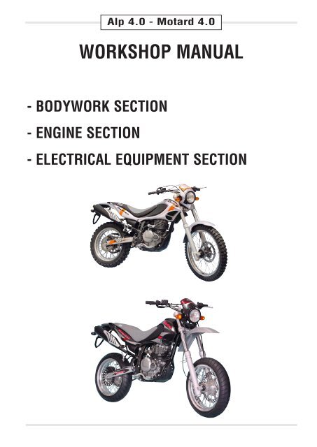
Alp 4.0 - Motard 4.0<br />
<strong>WORKSHOP</strong> <strong>MANUAL</strong><br />
- BODYWORK SECTION<br />
- ENGINE SECTION<br />
- ELECTRICAL EQUIPMENT SECTION
Alp 4.0 - Motard 4.0<br />
<strong>WORKSHOP</strong> <strong>MANUAL</strong><br />
- BODYWORK SECTION<br />
Pag. 3
SPECIFICATIONS . . . . . . . . . . . . . . . . . . . . . . . . . . . . . . . . . . . . . . . . . . . . . . . . . . . . . . . . . . . . . . . . . . . . . . .pag. 5<br />
RECOMMENDED LUBRICANTS AND FLUIDS . . . . . . . . . . . . . . . . . . . . . . . . . . . . . . . . . . . . . . . . . . . . . . . . .pag. 5<br />
SCHEDULED MAINTENANCE . . . . . . . . . . . . . . . . . . . . . . . . . . . . . . . . . . . . . . . . . . . . . . . . . . . . . . . . . . . . . .pag. 6<br />
BODYWORK . . . . . . . . . . . . . . . . . . . . . . . . . . . . . . . . . . . . . . . . . . . . . . . . . . . . . . . . . . . . . . . . . . . . . . . . . . .pag. 7<br />
Removing the saddle . . . . . . . . . . . . . . . . . . . . . . . . . . . . . . . . . . . . . . . . . . . . . . . . . . . . . . . . . . . . . . . . . .pag. 7<br />
Disassembling rear handles . . . . . . . . . . . . . . . . . . . . . . . . . . . . . . . . . . . . . . . . . . . . . . . . . . . . . . . . . . . . .pag. 7<br />
Disassembling rear tail . . . . . . . . . . . . . . . . . . . . . . . . . . . . . . . . . . . . . . . . . . . . . . . . . . . . . . . . . . . . . . . . .pag. 7<br />
Disassembling front sides . . . . . . . . . . . . . . . . . . . . . . . . . . . . . . . . . . . . . . . . . . . . . . . . . . . . . . . . . . . . . . .pag. 7<br />
Disassembling rear sides . . . . . . . . . . . . . . . . . . . . . . . . . . . . . . . . . . . . . . . . . . . . . . . . . . . . . . . . . . . . . . .pag. 8<br />
Removing the fuel tank . . . . . . . . . . . . . . . . . . . . . . . . . . . . . . . . . . . . . . . . . . . . . . . . . . . . . . . . . . . . . . . . .pag. 8<br />
Disassembling front optic support group . . . . . . . . . . . . . . . . . . . . . . . . . . . . . . . . . . . . . . . . . . . . . . . . . . . .pag. 8<br />
Removing the headlight . . . . . . . . . . . . . . . . . . . . . . . . . . . . . . . . . . . . . . . . . . . . . . . . . . . . . . . . . . . . . . . .pag. 8<br />
Removal of the fender and plate holder . . . . . . . . . . . . . . . . . . . . . . . . . . . . . . . . . . . . . . . . . . . . . . . . . . . . .pag. 8<br />
Removing the stand . . . . . . . . . . . . . . . . . . . . . . . . . . . . . . . . . . . . . . . . . . . . . . . . . . . . . . . . . . . . . . . . . . .pag. 9<br />
Removing the passenger's footr<strong>est</strong>s . . . . . . . . . . . . . . . . . . . . . . . . . . . . . . . . . . . . . . . . . . . . . . . . . . . . . . .pag. 9<br />
REMOVING AIR FILTER . . . . . . . . . . . . . . . . . . . . . . . . . . . . . . . . . . . . . . . . . . . . . . . . . . . . . . . . . . . . . . . . . .pag. 10<br />
REPLACING THE HEADLIGHT BULB . . . . . . . . . . . . . . . . . . . . . . . . . . . . . . . . . . . . . . . . . . . . . . . . . . . . . . . .pag. 11<br />
REPLACING THE REAR LIGHT BULB . . . . . . . . . . . . . . . . . . . . . . . . . . . . . . . . . . . . . . . . . . . . . . . . . . . . . . .pag. 11<br />
REPLACING THE TURN INDICATOR BULBS . . . . . . . . . . . . . . . . . . . . . . . . . . . . . . . . . . . . . . . . . . . . . . . . . .pag. 11<br />
REPLACING THE INSTRUMENT PANEL BULBS . . . . . . . . . . . . . . . . . . . . . . . . . . . . . . . . . . . . . . . . . . . . . . .pag. 11<br />
DISASSEMBLING THE FORK . . . . . . . . . . . . . . . . . . . . . . . . . . . . . . . . . . . . . . . . . . . . . . . . . . . . . . . . . . . . . .pag. 12<br />
FORK OIL . . . . . . . . . . . . . . . . . . . . . . . . . . . . . . . . . . . . . . . . . . . . . . . . . . . . . . . . . . . . . . . . . . . . . . . . . . . . .pag. 13<br />
BRAKING SYSTEM . . . . . . . . . . . . . . . . . . . . . . . . . . . . . . . . . . . . . . . . . . . . . . . . . . . . . . . . . . . . . . . . . . . . . .pag. 14<br />
Front brake . . . . . . . . . . . . . . . . . . . . . . . . . . . . . . . . . . . . . . . . . . . . . . . . . . . . . . . . . . . . . . . . . . . . . . . . . .pag. 14<br />
Rear brake . . . . . . . . . . . . . . . . . . . . . . . . . . . . . . . . . . . . . . . . . . . . . . . . . . . . . . . . . . . . . . . . . . . . . . . . . .pag. 14<br />
REPLACING THE FRONT BRAKE PADS . . . . . . . . . . . . . . . . . . . . . . . . . . . . . . . . . . . . . . . . . . . . . . . . . . . . .pag. 15<br />
ALP 4.0 front brake . . . . . . . . . . . . . . . . . . . . . . . . . . . . . . . . . . . . . . . . . . . . . . . . . . . . . . . . . . . . . . . . . . . .pag. 15<br />
MOTARD 4.0 front brake . . . . . . . . . . . . . . . . . . . . . . . . . . . . . . . . . . . . . . . . . . . . . . . . . . . . . . . . . . . . . . . .pag. 15<br />
BRAKE PUMP OIL - BLEEDING THE BRAKES . . . . . . . . . . . . . . . . . . . . . . . . . . . . . . . . . . . . . . . . . . . . . . . . .pag. 15<br />
Front brake . . . . . . . . . . . . . . . . . . . . . . . . . . . . . . . . . . . . . . . . . . . . . . . . . . . . . . . . . . . . . . . . . . . . . . . . . .pag. 15<br />
Rear brake . . . . . . . . . . . . . . . . . . . . . . . . . . . . . . . . . . . . . . . . . . . . . . . . . . . . . . . . . . . . . . . . . . . . . . . . . .pag. 15<br />
Bleeding the front brake . . . . . . . . . . . . . . . . . . . . . . . . . . . . . . . . . . . . . . . . . . . . . . . . . . . . . . . . . . . . . . . .pag. 16<br />
Bleeding the rear brake . . . . . . . . . . . . . . . . . . . . . . . . . . . . . . . . . . . . . . . . . . . . . . . . . . . . . . . . . . . . . . . . .pag. 16<br />
ADJUSTING THE BRAKES . . . . . . . . . . . . . . . . . . . . . . . . . . . . . . . . . . . . . . . . . . . . . . . . . . . . . . . . . . . . . . . .pag. 18<br />
Front brake . . . . . . . . . . . . . . . . . . . . . . . . . . . . . . . . . . . . . . . . . . . . . . . . . . . . . . . . . . . . . . . . . . . . . . . . . .pag. 18<br />
Rear brake . . . . . . . . . . . . . . . . . . . . . . . . . . . . . . . . . . . . . . . . . . . . . . . . . . . . . . . . . . . . . . . . . . . . . . . . . .pag. 18<br />
ADJUSTING THE CLUTCH . . . . . . . . . . . . . . . . . . . . . . . . . . . . . . . . . . . . . . . . . . . . . . . . . . . . . . . . . . . . . . . .pag. 18<br />
CHECKING AND ADJUSTING THE STEERING PLAY . . . . . . . . . . . . . . . . . . . . . . . . . . . . . . . . . . . . . . . . . . . .pag. 18<br />
TENSIONING THE CHAIN . . . . . . . . . . . . . . . . . . . . . . . . . . . . . . . . . . . . . . . . . . . . . . . . . . . . . . . . . . . . . . . . .pag. 19<br />
ADJUSTING THE HEADLIGHT . . . . . . . . . . . . . . . . . . . . . . . . . . . . . . . . . . . . . . . . . . . . . . . . . . . . . . . . . . . . .pag. 19<br />
Pag. 4
SPECIFICATIONS<br />
MAXIMUM LOAD<br />
rider + passenger . . . . . . . . . . . . . . . . . . . . . . .340 (kg)<br />
VEHICLE’S KERB (DRY)<br />
weight . . . . . . . . . . . . . . . . . . . . . . . . . . . . . . . .135 (kg)<br />
DIMENSIONS - ALP 4.0<br />
overall length . . . . . . . . . . . . . . . . . . . . . . . . . .2185 mm<br />
overall width . . . . . . . . . . . . . . . . . . . . . . . . . . .860 mm<br />
overall height . . . . . . . . . . . . . . . . . . . . . . . . . .1230 mm<br />
wheelbase . . . . . . . . . . . . . . . . . . . . . . . . . . . .1410 mm<br />
saddle height . . . . . . . . . . . . . . . . . . . . . . . . . . .865 mm<br />
gro<strong>un</strong>d clearance . . . . . . . . . . . . . . . . . . . . . . . .300 mm<br />
DIMENSIONS - MOTARD 4.0<br />
overall length . . . . . . . . . . . . . . . . . . . . . . . . . .2160 mm<br />
overall width . . . . . . . . . . . . . . . . . . . . . . . . . . .860 mm<br />
overall height . . . . . . . . . . . . . . . . . . . . . . . . . .1220 mm<br />
wheelbase . . . . . . . . . . . . . . . . . . . . . . . . . . . .1410 mm<br />
saddle height . . . . . . . . . . . . . . . . . . . . . . . . . . .870 mm<br />
gro<strong>un</strong>d clearance . . . . . . . . . . . . . . . . . . . . . . . .305 mm<br />
FRAME<br />
. . . . . . . . . . . . . . . .steel, double closed cradle<br />
TYRES - ALP 4.0<br />
pressure kg/cm 2 . . . . . . . . . . . . . . . . .front 1,5 / rear 1,8<br />
TYRES - MOTARD 4.0<br />
pressure kg/cm 2 . . . . . . . . . . . . . . . . .front 2,0 / rear 2,2<br />
WHEEL DIMENSION - ALP 4.0<br />
front cover . . . . . . . . . . . . . . . . . . . . . . . .(90/90-21) 54R<br />
rear cover . . . . . . . .(140/80-18) 70R o (130/80-18) 66R<br />
front rim . . . . . . . . . . . . . . . . . . . . . . . . . . . . . . .1,85x21<br />
rear rim . . . . . . . . . . . . . . . . . . . . . . . . . . . . . . .3,00x18<br />
WHEEL DIMENSION - MOTARD 4.0<br />
front cover . . . . . . . . . . . . . . . . . . . . . . .(120/70-17) 54R<br />
rear cover . . . . . . . . . . . . . . . . . . . . . . .(150/60-17) 66R<br />
front rim . . . . . . . . . . . . . . . . . . . . . . . . . . . . . . .3,50x17<br />
rear rim . . . . . . . . . . . . . . . . . . . . . . . . . . . . . . .4,25x17<br />
CAPACITIES<br />
fuel tank . . . . . . . . . . . . . . . . . . . . . . . . . . . . . . .10,5 (lt)<br />
including reserve . . . . . . . . . . . . . . . . . . . . . . . . . . .3 (lt)<br />
engine oil . . . . . . . . . . . . . . . . . . . . . . . .oil change 1,9 lt<br />
with filter replacement 2,1 lt<br />
overhaul 2,3 lt<br />
average consumption . . . . . . . . . . . . . . . . . . . .25 Km/lt<br />
FRONT SUSPENSION<br />
Hydraulic fork with Ø 46 mm rods<br />
Leg oil capacity:<br />
right . . . . . . . . . . . . . . . . . . . . . . . . . . . . . . . . . . .570 cc<br />
left . . . . . . . . . . . . . . . . . . . . . . . . . . . . . . . . . . . .570 cc<br />
oil type . . . . . . . . . . . . . . . . . . . . .LIQUI MOLY RACING<br />
SUSPENSION OIL SAE 7,5<br />
oil level . . . . . . . . . . . . . . . .180 mm from tube upper rim<br />
with a fork at the end of the stroke<br />
and without springs<br />
trail . . . . . . . . . . . . . . . . . . . . . . . . . .101 mm (ALP 4.0)<br />
58 mm (MOTARD 4.0)<br />
REAR SUSPENSION<br />
Single progressive hydraulic shock absorber<br />
shock absorber travel . . . . . . . . . . . . . .83 mm (ALP 4.0)<br />
100 mm (MOTARD 4.0)<br />
FRONT BRAKE<br />
Ø 260 mm disc brake with hydraulic control (ALP 4.0)<br />
Ø 310 mm disc brake with hydraulic control (MOTARD<br />
4.0)<br />
REAR BRAKE (ALP 4.0 - MOTARD 4.0)<br />
Ø 220 mm disc brake with hydraulic control<br />
RECOMMENDED LUBRICANTS AND FLUIDS<br />
To maximize the vehicle’s performance and ensure many<br />
years of trouble-free operation, we recommend using the<br />
following products:<br />
PRODUCT TYPE SPECIFICATIONS<br />
ENGINE OIL IP extra raid 4 SAE 15W/50<br />
alternative<br />
TAMOIL sint future moto<br />
competition<br />
BRAKE FLUID<br />
TAMOIL brake fluid DOT4<br />
FORK OIL<br />
LIQUI MOLY RACING<br />
(570 cc RH and LH) SUSPENSION OIL SAE 7,5<br />
GREASE FOR LINKAGE IP AUTOGREASE MP<br />
TAMOIL TAMLITH GREASE 2<br />
Pag. 5
SCHEDULED MAINTENANCE<br />
Scheduled maintenance operations are designed to prolong the life of your vehicle and maintain its performance, safety<br />
and value <strong>un</strong>altered over time.<br />
SCHEDULED MAINTENANCE 350 cc<br />
Interval Km 1000 4000 8000<br />
Item months 15 30 45<br />
Exhaust pipe bolts - T T<br />
Air filter - P P<br />
Valves I I I<br />
Chain tension I I I<br />
Spark plug - I S<br />
Idle speed I I I<br />
Throttle cable play I I I<br />
Clutch I I I<br />
Engine oil S S S<br />
Engine oil filter S - S<br />
Drive chain I I I<br />
clean and lubricate every 1,000 km<br />
Brakes I I I<br />
Brake lines - I I<br />
replace every 4 years<br />
Brake fluid - I I<br />
replace every 2 years<br />
Tyres - I I<br />
Steering I - I<br />
Fork - I I<br />
Rear suspension - I I<br />
Frame nuts / bolts (boards) oil tubes T T T<br />
Motor oil net filter P - P<br />
I = Check and if necessary adjust, clean, lubricate or replace.<br />
P = Clean<br />
S = Replace/renew<br />
T = Tighten<br />
NOTE: For any service requirements, please contact Betamotor’s Authorized Service Network.<br />
Pag. 6
BODYWORK<br />
To facilitate checks and operations in certain areas of the vehicle,<br />
it is essential to remove the bodywork sections as described<br />
below.<br />
Removing the saddle<br />
• Unloosen the clamping screw A and then remove the saddle<br />
by pushing it towards the rear of the vehicle so as to disengage<br />
it from the hook on the fuel tank.<br />
A<br />
Disassembling rear handles<br />
• Unscrew the two clamping screws B then remove the other<br />
clamping screw E, positioned <strong>un</strong>der the rear mudguard and<br />
thus remove the handles C.<br />
B<br />
B<br />
D<br />
C<br />
Disassembling rear tail<br />
• Remove the clamping screw F and remove the tail D.<br />
F<br />
E<br />
Disassembling front sides<br />
• Unscrew the four clamping screws G (two on each side) and<br />
remove the two screws H.<br />
• Remove the front sides, being careful to remove the left side<br />
first and then the right side.<br />
H<br />
G<br />
Pag. 7
Disassembling rear sides<br />
• Unscrew the clamping screws N, after having removed the<br />
rear handles and thus slide the sides out.<br />
N<br />
Removing the fuel tank<br />
• Remove screw I fixing the fuel tank to the frame, detach the<br />
fuel cock line and then remove the tank by pulling it towards<br />
the rear of the vehicle.<br />
I<br />
Note:<br />
The tank can be completely removed along with the front sides,<br />
removing though, the two lower screws G.<br />
Disassembling front optic support group<br />
• Detach all the electrical connections and <strong>un</strong>screw the three<br />
fixing screws L, one of which located <strong>un</strong>der the headlight.<br />
L<br />
M<br />
Removing the headlight<br />
• Remove the optic group N by <strong>un</strong>screwing the right and left<br />
screw M.<br />
N<br />
Removal of the fender and plate holder<br />
• Loosen the three screws P that secure the fender and plate<br />
holder to the <strong>un</strong>der-carriage located below.<br />
• Disconnect the electric wires of the back lights and remove<br />
the plate holder.<br />
P<br />
Pag. 8
Removing the stand<br />
• Remove the stand switch by <strong>un</strong>screwing the only fixing screw<br />
C.<br />
• Carefully remove the return stand spring D and the stand<br />
itself.<br />
• The vehicle is equipped with retrieval switch on the stand, so<br />
it will thus be necessary to secure the switch's electrical connections.<br />
C<br />
D<br />
Removing the passenger's footr<strong>est</strong>s<br />
• Loosen the two screws E shown in the figure and remove the<br />
passenger's footr<strong>est</strong> complete with the frame fixing support.<br />
E<br />
Pag. 9
REMOVING AIR FILTER<br />
Follow these steps to gain access to the air filter.<br />
A<br />
• Slightly raise the carter tank A as in figure.<br />
• Remove plastic cover E and <strong>un</strong>screwing the three fixing<br />
screws B.<br />
• Remove filter C after loosening the filter retaining cover fixing<br />
screw D.<br />
• Wash it with soap and water.<br />
• Dry the filter.<br />
• Wet the filter with filter oil and then remove the excess oil to<br />
prevent it from dripping.<br />
• If necessary clean the inside of the filter box.<br />
• Refit the filter paying special attention to the seal of the rubber<br />
gasket, previously greased so as to close better F.<br />
B<br />
NOTE:<br />
If the filter is very dirty, first wash it with petrol and then with water<br />
and soap.<br />
If the filter is damaged, replace it immediately.<br />
E<br />
WARNING: After each operation check that no object is left in<br />
the filter box.<br />
Clean the filter every time the vehicle is used over rough gro<strong>un</strong>d.<br />
D<br />
F<br />
C<br />
Pag. 10
REPLACING THE HEADLIGHT BULB<br />
• Remove the headlight rim after <strong>un</strong>screwing the three fixing<br />
screws.<br />
• Remove the three reflector fixing screws A and pull out the reflector.<br />
• Detach the bulb connector.<br />
• Rotate the bulb holder anticlockwise and extract the burnt-out<br />
bulb.<br />
• Fit a new bulb taking care not to touch the bulb to avoid impairing<br />
its f<strong>un</strong>ction. Rotate the bulb holder clockwise to the<br />
stop.<br />
• Refit the connector, the reflector, and the headlight rim by following<br />
the reverse procedure to the removal.<br />
A<br />
REPLACING THE REAR LIGHT BULB<br />
• Remove the lens after <strong>un</strong>screwing the two fixing screws B.<br />
• Replace the defective bulb.<br />
The bulbs have bayonet bases. To remove them, press them<br />
lightly, rotate them 30° anticlockwise and then extract them.<br />
B<br />
REPLACING THE TURN INDICATOR BULBS<br />
• Loosen screw A and remove the lens.<br />
• Replace the defective bulb.<br />
The bulbs have bayonet bases. To remove them, press them<br />
lightly, rotate them 30° anticlockwise and the extract them.<br />
A<br />
REPLACING THE INSTRUMENT PANEL BULBS<br />
• After having removed the small front dome, remove the bulbs<br />
from the dashboard, which have been installed by pressure<br />
with a rubber top. Just pull the bulbs downwards by the rubber<br />
bases (not the wires) and then extract the bulbs from their<br />
seats.<br />
Pag. 11
DISASSEMBLING THE FORK<br />
Disassemble the fork as shown in the figure:<br />
1 Handlebar<br />
2 Head tube nut<br />
3 Fork head<br />
4 Clevis<br />
5 Mechanical cartridge<br />
6 Dust ring<br />
7 Seal ring<br />
8 LH leg<br />
9 Spring<br />
10 LH/RH tube assembly<br />
11 RH leg<br />
12 Plug with ring<br />
13 Bearing<br />
14 Lower bearing guard<br />
15 Upper bearing guard<br />
16 Fork<br />
17 Cross w/ fork head tube<br />
16<br />
17<br />
15<br />
14<br />
12<br />
13<br />
5<br />
3<br />
4<br />
2<br />
1<br />
11<br />
10<br />
9<br />
8<br />
6<br />
7<br />
8<br />
8<br />
5<br />
Pag. 12
FORK OIL<br />
Right / left-hand rod<br />
Follow these steps to renew the oil:<br />
C<br />
1)Remove the handle-bar by <strong>un</strong>screwing the four C clamping<br />
screws of the two D stand screws.<br />
D<br />
2)Unloosen the stem clamping screws B and C.<br />
3)Remove the lower plug (hexagonal screws in the fork sheath)<br />
and upper plug A.<br />
4)Let all the oil drain from the rod.<br />
5)Retighten the inferior cap of the fork sheath.<br />
A<br />
B<br />
C<br />
6)Pour in fresh oil of the type shown in the table on page 5.<br />
7)Fit and tighten upper plug A.<br />
8)Tighten in sequence, first the B screw, then the C screw and<br />
aging the B screw.<br />
A<br />
B<br />
C<br />
Pag. 13
BRAKING SYSTEM<br />
FRONT BRAKE<br />
Check<br />
To check the wear of the front brake, visually inspect the brake<br />
pad ends by locking at the brake caliper from the front. The<br />
brake linings should be at least 2 mm thick.<br />
If the linings are thinner, replace the pads immediately.<br />
NOTE: Carry out the control procedure respecting time intervals<br />
and mileage indicated on the chart on page 6.<br />
REAR BRAKE<br />
Check<br />
To check the wear of the rear brake, visually inspect the brake<br />
pad ends by locking at the brake caliper from above. The brake<br />
linings should be at least 2 mm thick.<br />
If the linings are thinner, replace the pads immediately.<br />
NOTE: Carry out the control procedure respecting time intervals<br />
and mileage indicated on the chart on page 6.<br />
Pag. 14
REPLACING THE FRONT BRAKE PADS<br />
ALP 4.0 FRONT BRAKE<br />
A<br />
Follow these steps to replace the pads:<br />
• Loosen the two screws A and remove the brake caliper.<br />
• Loosen the two screws B.<br />
• Extract the brake pads.<br />
• To refit the parts, follow the reverse procedure, using blockage-threads<br />
on the screws A.<br />
To avoid braking problems, take special care in ensuring that the<br />
screws are refitted properly.<br />
B<br />
Whenever the brake disc is removed, apply blockage-threads to<br />
the screws when refitting.<br />
MOTARD 4.0 FRONT BRAKE<br />
Follow these steps to replace the pads:<br />
• Disassemble the pincers from the special support C by <strong>un</strong>screwing<br />
the two screws A.<br />
• Loosen the two screws B.<br />
• Extract the brake pads.<br />
• To refit the parts, follow the reverse procedure, using blockage-threads<br />
on the screws A.<br />
To avoid braking problems, take special care in ensuring that the<br />
screws are refitted properly.<br />
Whenever the brake disc is removed, apply blockage-threads to<br />
the screws when refitting.<br />
A<br />
C<br />
B<br />
BRAKE PUMPS OIL - BLEEDING THE BRAKES<br />
Front brake<br />
Check that oil is present by locking through oil level sight A.<br />
The minimum oil level should never be lower than the mark on<br />
sight A. To r<strong>est</strong>ore the oil level, loosen the two screws B, lift cover<br />
C and pour in fresh oil.<br />
Keep the motor in a stable vertical position, possibly blocking<br />
the handle-bar, so as to avoid the brake oil from spilling out.<br />
C<br />
B<br />
A<br />
Rear brake<br />
Check that oil is present by looking through reservoir D. The oil<br />
level must never be below the minimum level line in relief on<br />
container D.<br />
For r<strong>est</strong>oring the oil level proceed as follows:<br />
E<br />
• Using an appropriate wrench, <strong>un</strong>screw the oil container clamping<br />
screw.<br />
• Slide the container out of its lot.<br />
• Carefully keep the brake oil container in a vertical position and<br />
open the cap E.<br />
• Wrap it with absorbing paper as in the figure.<br />
• Proceed with topping-up<br />
D<br />
Pag. 15
WARNING:<br />
The brake liquid is highly corrosive, so be very careful not to let<br />
it drip onto the varnished parts of the vehicle.<br />
WARNING:<br />
A spongy feel of the brake lever may be due to an air bubble in<br />
the braking system, in such case it is necessary to purge the<br />
brakes (page 16/17) or revert to an authorized mechanic as<br />
soon as possible.<br />
NOTE:<br />
For information on oil renewals, please refer to the chart on page<br />
6. Use the recommended lubricants indicate at page 5.<br />
Bleeding the front brake<br />
Follow these steps to bleed the front brake circuit:<br />
A<br />
• Remove rubber cap A from valve B.<br />
• Remove the oil reservoir cap.<br />
• Insert one end of a small tube into valve B and place the other<br />
end in a container.<br />
B<br />
• Unscrew valve B (while pulling the brake lever) and then<br />
pump by repeatedly actuating the brake lever <strong>un</strong>til oil starts<br />
flowing out continuously with no air bubbles. During this operation,<br />
it is important that the lever should not be released<br />
completely and that the brake pump reservoir should be continuously<br />
refilled to make up for the oil that is flowing out.<br />
• N.B. – Do not pump oil <strong>un</strong>less the tap is closed; keep the<br />
lever down and open the vent (with the lever down); then,<br />
shut the vent and let go of the lever.<br />
• Tighten the valve and extract the tube.<br />
• Replace the cap.<br />
Bleeding the rear brake<br />
Follow these steps to bleed the rear brake circuit:<br />
• First remove the protection mask C indicated in the figure.<br />
• Remove rubber cap D.<br />
• Remove the oil reservoir cap.<br />
• Insert one end of a small tube into valve E and place the other<br />
end in a container.<br />
C<br />
Pag. 16
• Unscrew valve E (while pulling the brake lever) and then<br />
pump by repeatedly actuating the brake lever <strong>un</strong>til oil starts<br />
flowing out with no air bubbles. During this operation, please<br />
do not let lever be completely released and the brake pump<br />
reservoir should be continuously refilled to make up for the oil<br />
that is flowing out.<br />
D<br />
• N.B. – Do not pump oil <strong>un</strong>less the tap is closed; keep the<br />
lever down and open the vent (with the lever down); then,<br />
shut the vent and let go of the lever.<br />
• Tighten the valve and extract the tube.<br />
• Replace the cap.<br />
E<br />
• Replace the protection mask C.<br />
Pag. 17
ADJUSTING<br />
ADJUSTING THE BRAKES<br />
A<br />
Front brake<br />
The front brake is a hydraulically operated disc brake, and therefore<br />
requires no adjustment.<br />
B<br />
Rear brake<br />
The rear brake is a hydraulically operated disc brake. The brake<br />
pedal can be adjusted for height by means of adjusters A and B.<br />
The brake lever play should never be less than 5 mm.<br />
ADJUSTING THE CLUTCH<br />
The only operation that may be required is the adjustment of the<br />
position of clutch lever C.<br />
The adjustment is obtained by means of adjuster D.<br />
After adjusting the lever with the adjusting screw, be sure to tighten<br />
stop E so as to lock the screw in the desired position.<br />
Note:<br />
The play of the clutch should range from 1 to 2 mm.<br />
D<br />
E<br />
C<br />
CHECKING AND ADJUSTING THE STEERING PLAY<br />
Periodically check the play of the steering head tube by moving<br />
the forks backwards and forwards as shown in the figure. If any<br />
play is felt, carry out the adjustment by following these steps:<br />
• Unscrew the four screws C.<br />
• Pull out handlebar D, paying special attention to clevises E.<br />
• Loosen nut F.<br />
• Reduce the play by turning ring G.<br />
C<br />
To refit the parts, follow the reverse procedure.<br />
Note:<br />
Proper adjustment must leave no play and cause no stiffness,<br />
and allow the steering to rotate smoothly. Check the fitting direction<br />
of the clevises as it can alter the geometry of the handlebar.<br />
D<br />
E<br />
G<br />
F<br />
E<br />
Pag. 18
TENSIONING THE CHAIN<br />
To ensure the drive chain a longer life, it is advisable to periodically<br />
check its tension. Always maintain the chain clean and lubricated.<br />
If the chain play exceeds 20 mm, tension the chain by<br />
following these steps:<br />
A<br />
• Loosen the nuts on both arms of the rear fork.<br />
• Turn nut B <strong>un</strong>til the desired chain tension is obtained.<br />
B<br />
• Perform the same operation on nut B on the other side of the<br />
swing arm <strong>un</strong>til the wheel is perfectly aligned.<br />
• Clamp the co<strong>un</strong>ter-nut A on both arms of the rear fork.<br />
20 mm<br />
ADJUSTING THE HEADLIGHT<br />
• The headlight beam is adjusted manually after loosening the<br />
screws on either side of the headlight with an Allen key.<br />
• Periodically check the direction of the beam. The beam can<br />
only be adjusted vertically.<br />
• Place the vehicle on level gro<strong>un</strong>d (but not on the stand) 10<br />
metres from a vertical wall.<br />
h<br />
9/10h<br />
• Measure the height of the headlight centre above the gro<strong>un</strong>d<br />
and then draw a cross on the wall at 9/10 of the height of the<br />
headlight centre.<br />
10 m<br />
• Turn on the low beam, get on the motorbike and check that<br />
the headlight beam on the wall is slightly lower than the cross<br />
drawn previously.<br />
Pag. 19
Alp 4.0 - Motard 4.0<br />
<strong>WORKSHOP</strong> <strong>MANUAL</strong><br />
- ENGINE SECTION
TOOLING . . . . . . . . . . . . . . . . . . . . . . . . . . . . . . . . . . . . . . . . . . . . . . . . . . . . . . . . . . . . . . . . . . . . . . . . . . . . . .pag. 24<br />
ENGINE - SPECIFICATIONS . . . . . . . . . . . . . . . . . . . . . . . . . . . . . . . . . . . . . . . . . . . . . . . . . . . . . . . . . . . . . . .pag. 25<br />
MOTOR OIL AND FILTER OIL . . . . . . . . . . . . . . . . . . . . . . . . . . . . . . . . . . . . . . . . . . . . . . . . . . . . . . . . . . . . . .pag. 25<br />
Procedure for oil level check . . . . . . . . . . . . . . . . . . . . . . . . . . . . . . . . . . . . . . . . . . . . . . . . . . . . . . . . . . . . .pag. 25<br />
Oil level check . . . . . . . . . . . . . . . . . . . . . . . . . . . . . . . . . . . . . . . . . . . . . . . . . . . . . . . . . . . . . . . . . . . . . . . .pag. 26<br />
Substituting oil . . . . . . . . . . . . . . . . . . . . . . . . . . . . . . . . . . . . . . . . . . . . . . . . . . . . . . . . . . . . . . . . . . . . . . . .pag. 26<br />
Substituting oil filter . . . . . . . . . . . . . . . . . . . . . . . . . . . . . . . . . . . . . . . . . . . . . . . . . . . . . . . . . . . . . . . . . . . .pag. 27<br />
Emptying oil from the tank . . . . . . . . . . . . . . . . . . . . . . . . . . . . . . . . . . . . . . . . . . . . . . . . . . . . . . . . . . . . . . .pag. 27<br />
SPARK PLUG . . . . . . . . . . . . . . . . . . . . . . . . . . . . . . . . . . . . . . . . . . . . . . . . . . . . . . . . . . . . . . . . . . . . . . . . . . .pag. 29<br />
Carbon formation . . . . . . . . . . . . . . . . . . . . . . . . . . . . . . . . . . . . . . . . . . . . . . . . . . . . . . . . . . . . . . . . . . . . . .pag. 29<br />
Spark gap . . . . . . . . . . . . . . . . . . . . . . . . . . . . . . . . . . . . . . . . . . . . . . . . . . . . . . . . . . . . . . . . . . . . . . . . . . .pag. 29<br />
Condition of electrodes . . . . . . . . . . . . . . . . . . . . . . . . . . . . . . . . . . . . . . . . . . . . . . . . . . . . . . . . . . . . . . . . .pag. 29<br />
CARBURETTOR . . . . . . . . . . . . . . . . . . . . . . . . . . . . . . . . . . . . . . . . . . . . . . . . . . . . . . . . . . . . . . . . . . . . . . . .pag. 30<br />
CHECKING COMPRESSION . . . . . . . . . . . . . . . . . . . . . . . . . . . . . . . . . . . . . . . . . . . . . . . . . . . . . . . . . . . . . . .pag. 30<br />
Measuring compression . . . . . . . . . . . . . . . . . . . . . . . . . . . . . . . . . . . . . . . . . . . . . . . . . . . . . . . . . . . . . . . . .pag. 30<br />
CHECKING THE OIL PRESSURE . . . . . . . . . . . . . . . . . . . . . . . . . . . . . . . . . . . . . . . . . . . . . . . . . . . . . . . . . . .pag. 31<br />
Oil pressure specification . . . . . . . . . . . . . . . . . . . . . . . . . . . . . . . . . . . . . . . . . . . . . . . . . . . . . . . . . . . . . . . .pag. 31<br />
Low oil pressure . . . . . . . . . . . . . . . . . . . . . . . . . . . . . . . . . . . . . . . . . . . . . . . . . . . . . . . . . . . . . . . . . . . . . .pag. 31<br />
High oil pressure . . . . . . . . . . . . . . . . . . . . . . . . . . . . . . . . . . . . . . . . . . . . . . . . . . . . . . . . . . . . . . . . . . . . . .pag. 31<br />
Measuring the oil pressure . . . . . . . . . . . . . . . . . . . . . . . . . . . . . . . . . . . . . . . . . . . . . . . . . . . . . . . . . . . . . . .pag. 31<br />
ENGINE TIGHTENING TORQUES . . . . . . . . . . . . . . . . . . . . . . . . . . . . . . . . . . . . . . . . . . . . . . . . . . . . . . . . . . .pag. 32<br />
VALVES CLEARANCE ADJUSTMENT . . . . . . . . . . . . . . . . . . . . . . . . . . . . . . . . . . . . . . . . . . . . . . . . . . . . . . . .pag. 32<br />
CHECKING AND MAINTAINING ENGINE COMPONENTS . . . . . . . . . . . . . . . . . . . . . . . . . . . . . . . . . . . . . . . . .pag. 33<br />
MAINTAINING THE CYLINDER HEAD COVER . . . . . . . . . . . . . . . . . . . . . . . . . . . . . . . . . . . . . . . . . . . . . . .pag. 33<br />
CYLINDER HEAD COVER DISTORTION . . . . . . . . . . . . . . . . . . . . . . . . . . . . . . . . . . . . . . . . . . . . . . . . . . .pag. 33<br />
CAMSHAFT . . . . . . . . . . . . . . . . . . . . . . . . . . . . . . . . . . . . . . . . . . . . . . . . . . . . . . . . . . . . . . . . . . . . . . . . .pag. 34<br />
ROCKER ARM PIN OUTSIDE DIAMETER . . . . . . . . . . . . . . . . . . . . . . . . . . . . . . . . . . . . . . . . . . . . . . . . . .pag. 34<br />
ROCKER ARM INSIDE DIAMETER . . . . . . . . . . . . . . . . . . . . . . . . . . . . . . . . . . . . . . . . . . . . . . . . . . . . . . . .pag. 34<br />
REFITTING THE ROCKER ARMS AND THE ROCKER ARM PINS . . . . . . . . . . . . . . . . . . . . . . . . . . . . . . . .pag. 34<br />
MAINTAINING THE CYLINDER HEAD . . . . . . . . . . . . . . . . . . . . . . . . . . . . . . . . . . . . . . . . . . . . . . . . . . . . .pag. 35<br />
CYLINDER HEAD DISTORTION . . . . . . . . . . . . . . . . . . . . . . . . . . . . . . . . . . . . . . . . . . . . . . . . . . . . . . . . . .pag. 35<br />
VALVE SEALING SURFACE WEAR . . . . . . . . . . . . . . . . . . . . . . . . . . . . . . . . . . . . . . . . . . . . . . . . . . . . . . .pag. 35<br />
VALVE STEM RUN OUT . . . . . . . . . . . . . . . . . . . . . . . . . . . . . . . . . . . . . . . . . . . . . . . . . . . . . . . . . . . . . . . .pag. 35<br />
VALVE HEAD RADIAL RUNOUT . . . . . . . . . . . . . . . . . . . . . . . . . . . . . . . . . . . . . . . . . . . . . . . . . . . . . . . . . .pag. 36<br />
VALVE STEM DEFLECTION . . . . . . . . . . . . . . . . . . . . . . . . . . . . . . . . . . . . . . . . . . . . . . . . . . . . . . . . . . . . .pag. 36<br />
VALVE STEM WEAR . . . . . . . . . . . . . . . . . . . . . . . . . . . . . . . . . . . . . . . . . . . . . . . . . . . . . . . . . . . . . . . . . . .pag. 36<br />
MAINTAINING THE VALVE GUIDES . . . . . . . . . . . . . . . . . . . . . . . . . . . . . . . . . . . . . . . . . . . . . . . . . . . . . . .pag. 36<br />
VALVE SEAT WIDTH . . . . . . . . . . . . . . . . . . . . . . . . . . . . . . . . . . . . . . . . . . . . . . . . . . . . . . . . . . . . . . . . . . .pag. 38<br />
REFACING THE VALVE SEAT . . . . . . . . . . . . . . . . . . . . . . . . . . . . . . . . . . . . . . . . . . . . . . . . . . . . . . . . . . . .pag. 38<br />
CONDITION OF THE VALVE STEM END . . . . . . . . . . . . . . . . . . . . . . . . . . . . . . . . . . . . . . . . . . . . . . . . . . .pag. 40<br />
VALVE SPRING . . . . . . . . . . . . . . . . . . . . . . . . . . . . . . . . . . . . . . . . . . . . . . . . . . . . . . . . . . . . . . . . . . . . . .pag. 40<br />
REFITTING THE VALVES AND THE VALVE SPRINGS . . . . . . . . . . . . . . . . . . . . . . . . . . . . . . . . . . . . . . . . .pag. 40<br />
CAMSHAFT WEAR . . . . . . . . . . . . . . . . . . . . . . . . . . . . . . . . . . . . . . . . . . . . . . . . . . . . . . . . . . . . . . . . . . . .pag. 41<br />
CAMSHAFT JOURNAL WEAR . . . . . . . . . . . . . . . . . . . . . . . . . . . . . . . . . . . . . . . . . . . . . . . . . . . . . . . . . . .pag. 41<br />
CAMSHAFT RUNOUT . . . . . . . . . . . . . . . . . . . . . . . . . . . . . . . . . . . . . . . . . . . . . . . . . . . . . . . . . . . . . . . . . .pag. 42<br />
CYLINDER DISTORTION . . . . . . . . . . . . . . . . . . . . . . . . . . . . . . . . . . . . . . . . . . . . . . . . . . . . . . . . . . . . . . .pag. 42<br />
CYLINDER BORE . . . . . . . . . . . . . . . . . . . . . . . . . . . . . . . . . . . . . . . . . . . . . . . . . . . . . . . . . . . . . . . . . . . . .pag. 42<br />
PISTON DIAMETER . . . . . . . . . . . . . . . . . . . . . . . . . . . . . . . . . . . . . . . . . . . . . . . . . . . . . . . . . . . . . . . . . . .pag. 43<br />
CYLINDER-PISTON CLEARANCE . . . . . . . . . . . . . . . . . . . . . . . . . . . . . . . . . . . . . . . . . . . . . . . . . . . . . . . .pag. 43<br />
PISTON RING-PISTON GROOVE CLEARANCE . . . . . . . . . . . . . . . . . . . . . . . . . . . . . . . . . . . . . . . . . . . . . .pag. 43<br />
PISTON RING END GAP . . . . . . . . . . . . . . . . . . . . . . . . . . . . . . . . . . . . . . . . . . . . . . . . . . . . . . . . . . . . . . .pag. 43<br />
OVERSIZE PISTON RINGS . . . . . . . . . . . . . . . . . . . . . . . . . . . . . . . . . . . . . . . . . . . . . . . . . . . . . . . . . . . . .pag. 44<br />
PISTON PIN AND PISTON PIN BORE . . . . . . . . . . . . . . . . . . . . . . . . . . . . . . . . . . . . . . . . . . . . . . . . . . . . .pag. 44<br />
CONNECTING ROD SMALL END INSIDE DIAMETER . . . . . . . . . . . . . . . . . . . . . . . . . . . . . . . . . . . . . . . . .pag. 45<br />
CONNECTING ROD DEFLECTION AND CONNECTING ROD BIG END SIDE PLAY . . . . . . . . . . . . . . . . . .pag. 45<br />
CRANKSHAFT RUNOUT . . . . . . . . . . . . . . . . . . . . . . . . . . . . . . . . . . . . . . . . . . . . . . . . . . . . . . . . . . . . . . .pag. 45<br />
CLUTCH DRIVING PLATES . . . . . . . . . . . . . . . . . . . . . . . . . . . . . . . . . . . . . . . . . . . . . . . . . . . . . . . . . . . . .pag. 46<br />
CLUTCH DRIVEN PLATES . . . . . . . . . . . . . . . . . . . . . . . . . . . . . . . . . . . . . . . . . . . . . . . . . . . . . . . . . . . . . .pag. 46<br />
CLUTCH SPRING FREE LENGTH . . . . . . . . . . . . . . . . . . . . . . . . . . . . . . . . . . . . . . . . . . . . . . . . . . . . . . . .pag. 46<br />
STARTER COUPLING AND STARTER DRIVEN GEAR BEARING . . . . . . . . . . . . . . . . . . . . . . . . . . . . . . . . .pag. 47<br />
Starter coupling . . . . . . . . . . . . . . . . . . . . . . . . . . . . . . . . . . . . . . . . . . . . . . . . . . . . . . . . . . . . . . . . . . . .pag. 47<br />
Pag. 22
Starter driven gear bearing . . . . . . . . . . . . . . . . . . . . . . . . . . . . . . . . . . . . . . . . . . . . . . . . . . . . . . . . . . . .pag. 47<br />
Removal . . . . . . . . . . . . . . . . . . . . . . . . . . . . . . . . . . . . . . . . . . . . . . . . . . . . . . . . . . . . . . . . . . . . . . .pag. 47<br />
Refitting . . . . . . . . . . . . . . . . . . . . . . . . . . . . . . . . . . . . . . . . . . . . . . . . . . . . . . . . . . . . . . . . . . . . . . .pag. 47<br />
TRANSMISSION . . . . . . . . . . . . . . . . . . . . . . . . . . . . . . . . . . . . . . . . . . . . . . . . . . . . . . . . . . . . . . . . . . . . . .pag. 48<br />
Disassembly . . . . . . . . . . . . . . . . . . . . . . . . . . . . . . . . . . . . . . . . . . . . . . . . . . . . . . . . . . . . . . . . . . . . . . .pag. 48<br />
DRIVING SHAFT AND COUNTERSHAFT . . . . . . . . . . . . . . . . . . . . . . . . . . . . . . . . . . . . . . . . . . . . . . . . . . .pag. 49<br />
Refitting . . . . . . . . . . . . . . . . . . . . . . . . . . . . . . . . . . . . . . . . . . . . . . . . . . . . . . . . . . . . . . . . . . . . . . . . . .pag. 49<br />
FORK-GROOVE CLEARANCE . . . . . . . . . . . . . . . . . . . . . . . . . . . . . . . . . . . . . . . . . . . . . . . . . . . . . . . . . . .pag. 49<br />
CRANKCASE BEARINGS . . . . . . . . . . . . . . . . . . . . . . . . . . . . . . . . . . . . . . . . . . . . . . . . . . . . . . . . . . . . . . .pag. 50<br />
REASSEMBLING THE ENGINE . . . . . . . . . . . . . . . . . . . . . . . . . . . . . . . . . . . . . . . . . . . . . . . . . . . . . . . . . .pag. 50<br />
CRANKCASE BEARINGS . . . . . . . . . . . . . . . . . . . . . . . . . . . . . . . . . . . . . . . . . . . . . . . . . . . . . . . . . . . . . . .pag. 50<br />
OIL SEALS . . . . . . . . . . . . . . . . . . . . . . . . . . . . . . . . . . . . . . . . . . . . . . . . . . . . . . . . . . . . . . . . . . . . . . . . . .pag. 51<br />
CRANKSHAFT . . . . . . . . . . . . . . . . . . . . . . . . . . . . . . . . . . . . . . . . . . . . . . . . . . . . . . . . . . . . . . . . . . . . . . .pag. 51<br />
TRANSMISSION . . . . . . . . . . . . . . . . . . . . . . . . . . . . . . . . . . . . . . . . . . . . . . . . . . . . . . . . . . . . . . . . . . . . . .pag. 51<br />
CRANKCASE . . . . . . . . . . . . . . . . . . . . . . . . . . . . . . . . . . . . . . . . . . . . . . . . . . . . . . . . . . . . . . . . . . . . . . . .pag. 52<br />
CAM CHAIN AND PRIMARY DRIVE GEAR . . . . . . . . . . . . . . . . . . . . . . . . . . . . . . . . . . . . . . . . . . . . . . . . . .pag. 53<br />
CAM DRIVEN GEAR AND GEARSHIFT SHAFT . . . . . . . . . . . . . . . . . . . . . . . . . . . . . . . . . . . . . . . . . . . . . .pag. 53<br />
OIL PUMP . . . . . . . . . . . . . . . . . . . . . . . . . . . . . . . . . . . . . . . . . . . . . . . . . . . . . . . . . . . . . . . . . . . . . . . . . . .pag. 53<br />
CLUTCH THROW-OUT CAMSHAFT . . . . . . . . . . . . . . . . . . . . . . . . . . . . . . . . . . . . . . . . . . . . . . . . . . . . . . .pag. 54<br />
CLUTCH . . . . . . . . . . . . . . . . . . . . . . . . . . . . . . . . . . . . . . . . . . . . . . . . . . . . . . . . . . . . . . . . . . . . . . . . . . . .pag. 54<br />
OIL FILTER . . . . . . . . . . . . . . . . . . . . . . . . . . . . . . . . . . . . . . . . . . . . . . . . . . . . . . . . . . . . . . . . . . . . . . . . . .pag. 54<br />
TIMING CHAIN, STARTER GEARS AND GENERATOR . . . . . . . . . . . . . . . . . . . . . . . . . . . . . . . . . . . . . . . .pag. 54<br />
OIL RING . . . . . . . . . . . . . . . . . . . . . . . . . . . . . . . . . . . . . . . . . . . . . . . . . . . . . . . . . . . . . . . . . . . . . . . . . . .pag. 55<br />
TOP RING AND 2ND RING . . . . . . . . . . . . . . . . . . . . . . . . . . . . . . . . . . . . . . . . . . . . . . . . . . . . . . . . . . . . . .pag. 55<br />
PISTON . . . . . . . . . . . . . . . . . . . . . . . . . . . . . . . . . . . . . . . . . . . . . . . . . . . . . . . . . . . . . . . . . . . . . . . . . . . . .pag. 56<br />
CYLINDER . . . . . . . . . . . . . . . . . . . . . . . . . . . . . . . . . . . . . . . . . . . . . . . . . . . . . . . . . . . . . . . . . . . . . . . . . .pag. 56<br />
CYLINDER HEAD . . . . . . . . . . . . . . . . . . . . . . . . . . . . . . . . . . . . . . . . . . . . . . . . . . . . . . . . . . . . . . . . . . . . .pag. 56<br />
CAMSHAFT . . . . . . . . . . . . . . . . . . . . . . . . . . . . . . . . . . . . . . . . . . . . . . . . . . . . . . . . . . . . . . . . . . . . . . . . .pag. 57<br />
CYLINDER HEAD COVER . . . . . . . . . . . . . . . . . . . . . . . . . . . . . . . . . . . . . . . . . . . . . . . . . . . . . . . . . . . . . .pag. 58<br />
CHAIN TIGHTENER REGULATOR . . . . . . . . . . . . . . . . . . . . . . . . . . . . . . . . . . . . . . . . . . . . . . . . . . . . . . . .pag. 58<br />
VALVES INSPECTION COVER . . . . . . . . . . . . . . . . . . . . . . . . . . . . . . . . . . . . . . . . . . . . . . . . . . . . . . . . . . .pag. 59<br />
OIL PIPE . . . . . . . . . . . . . . . . . . . . . . . . . . . . . . . . . . . . . . . . . . . . . . . . . . . . . . . . . . . . . . . . . . . . . . . . . . . .pag. 59<br />
MAGNETO COVER . . . . . . . . . . . . . . . . . . . . . . . . . . . . . . . . . . . . . . . . . . . . . . . . . . . . . . . . . . . . . . . . . . . .pag. 60<br />
CARBURETTOR . . . . . . . . . . . . . . . . . . . . . . . . . . . . . . . . . . . . . . . . . . . . . . . . . . . . . . . . . . . . . . . . . . . . . . . .pag. 62<br />
SPECIFICATIONS . . . . . . . . . . . . . . . . . . . . . . . . . . . . . . . . . . . . . . . . . . . . . . . . . . . . . . . . . . . . . . . . . . . . .pag. 63<br />
CHECKING THE CARBURETTOR JETS . . . . . . . . . . . . . . . . . . . . . . . . . . . . . . . . . . . . . . . . . . . . . . . . . . . .pag. 64<br />
CHECKING THE NEEDLE VALVE . . . . . . . . . . . . . . . . . . . . . . . . . . . . . . . . . . . . . . . . . . . . . . . . . . . . . . . . .pag. 64<br />
ADJUSTING THE FLOAT LEVEL . . . . . . . . . . . . . . . . . . . . . . . . . . . . . . . . . . . . . . . . . . . . . . . . . . . . . . . . .pag. 64<br />
REASSEMBLY AND REINSTALLATION . . . . . . . . . . . . . . . . . . . . . . . . . . . . . . . . . . . . . . . . . . . . . . . . . . . . .pag. 64<br />
VALVE + GUIDE . . . . . . . . . . . . . . . . . . . . . . . . . . . . . . . . . . . . . . . . . . . . . . . . . . . . . . . . . . . . . . . . . . . . . .pag. 65<br />
CAMSHAFT + CYLINDER HEAD . . . . . . . . . . . . . . . . . . . . . . . . . . . . . . . . . . . . . . . . . . . . . . . . . . . . . . . . .pag. 65<br />
CYLINDER + PISTON + PISTON RING . . . . . . . . . . . . . . . . . . . . . . . . . . . . . . . . . . . . . . . . . . . . . . . . . . . . .pag. 66<br />
CYLINDER + PISTON + PISTON RING . . . . . . . . . . . . . . . . . . . . . . . . . . . . . . . . . . . . . . . . . . . . . . . . . . . . .pag. 66<br />
CONNECTING ROD + CRANKSHAFT . . . . . . . . . . . . . . . . . . . . . . . . . . . . . . . . . . . . . . . . . . . . . . . . . . . . .pag. 66<br />
OIL PUMP . . . . . . . . . . . . . . . . . . . . . . . . . . . . . . . . . . . . . . . . . . . . . . . . . . . . . . . . . . . . . . . . . . . . . . . . . . .pag. 67<br />
CLUTCH . . . . . . . . . . . . . . . . . . . . . . . . . . . . . . . . . . . . . . . . . . . . . . . . . . . . . . . . . . . . . . . . . . . . . . . . . . . .pag. 67<br />
TRANSMISSION + DRIVE CHAIN . . . . . . . . . . . . . . . . . . . . . . . . . . . . . . . . . . . . . . . . . . . . . . . . . . . . . . . . .pag. 67<br />
E2 TYPE APPROVAL . . . . . . . . . . . . . . . . . . . . . . . . . . . . . . . . . . . . . . . . . . . . . . . . . . . . . . . . . . . . . . . . . . . . .pag. 68<br />
AIS VALVE . . . . . . . . . . . . . . . . . . . . . . . . . . . . . . . . . . . . . . . . . . . . . . . . . . . . . . . . . . . . . . . . . . . . . . . . . .pag. 68<br />
Removal of the AIS valve . . . . . . . . . . . . . . . . . . . . . . . . . . . . . . . . . . . . . . . . . . . . . . . . . . . . . . . . . . . . .pag. 68<br />
ELECTRICAL DEVICES . . . . . . . . . . . . . . . . . . . . . . . . . . . . . . . . . . . . . . . . . . . . . . . . . . . . . . . . . . . . . . . .pag. 69<br />
Pag. 23
TOOLING<br />
01.00030.000<br />
Driving shaft assembly<br />
01.00031.000<br />
Tool for pressing valve springs (disassembly)<br />
01.00033.000<br />
Flywheel extractor<br />
01.00034.000<br />
Tool for central crankcases parting<br />
01.00035.000<br />
Adjustable wrench for drum stop<br />
01.00036.000<br />
Tool for valves adjustment<br />
01.00038.000<br />
Adapter for compressing valve<br />
springs<br />
Pag. 24
ENGINE - SPECIFICATIONS<br />
type . . . . . . . . . . . . . . . . . . . . . . . . . . . .SUZUKI 350 cc<br />
single-cylinder, four-stroke<br />
bore x stroke . . . . . . . . . . . . . . . . . . . . .79,0 x 71,2 mm<br />
displacement . . . . . . . . . . . . . . . . . . . . .349 cm 3 350 cc<br />
compression ratio . . . . . . . . . . . . . . . . . . . .9,5:1 350 cc<br />
carburettor . . . . . . . . . . . . .MIKUNI BST33 14D9 350 cc<br />
lubrication . . . . . . . . . . . . . . . . . . . .pressure with pump<br />
fuel system . . . . . . . . .petrol (<strong>un</strong>leaded, with a minimum<br />
octane number of 95),<br />
by carburettor<br />
cooling system . . . . . . . . . . . . . . . . . . .by air circulation<br />
clutch . . . . . . . . . . . . . . . . . . . . .multiple-disc in oil bath<br />
transmission . . . . . . . .6-speed, with constant-mesh gears<br />
Starting . . . . . . . . . . . . . . . . . . . . . . . . . . . . . . .electric<br />
Engine oil . . . . . . . . . . . . . .IP extra raid 4 SAE 15W/50<br />
. . . . . . . . . . . . . .TAMOIL sint future moto competition<br />
Engine oil capacity . . . . . . . . . . . . . . . . .oil change 1,9 lt<br />
with filter replacement 2,1 lt<br />
overhaul 2,3 lt<br />
MOTOR OIL AND FILTER OIL<br />
Motor oil level<br />
On this vehicle oil check must be carried out while the motor is<br />
hot, since the oil tank is positioned higher than the motor (see<br />
scheme).<br />
Procedure for oil level check<br />
• Verify the presence of oil inside the motor block. In order to do<br />
this, loosen the oil level inspection screw A on the motor block<br />
and verify oil draw. This way, we can be assured that there is<br />
a certain quantity of motor oil inside the motor block.<br />
A<br />
• In case there is a lack of oil drawn, proceed by topping-up the<br />
oil (1.9 lt) through the L oil filling cap (see figure).<br />
L<br />
Pag. 25
Oil level check<br />
• Start the motor r<strong>un</strong>ning and let it r<strong>un</strong> on minimum for 3 minutes.<br />
• Turn the motor off and wait one minute.<br />
• Remove the cap from the oil filling opening.<br />
• Using a clean rag, remove traces of oil from the level rod.<br />
• Holding the motor-bike in a vertical position, reinsert the level<br />
rod <strong>un</strong>til it touches the border of the oil filling opening, without,<br />
though, screwing top on.<br />
• Retrieve the oil level rod and check the oil level. The oil level<br />
indicated on the rod should be between M (MAX) and N (MIN).<br />
If the oil level should be below the N line, add new oil into the<br />
oil filling opening <strong>un</strong>til the oil level is parallel to M (MAX).<br />
WARNING:<br />
Never drive the motor-bike if the oil level of the motor is below<br />
the N line (MIN) on the level rod.<br />
Never fill up the motor with oil above the M level line (MAX).<br />
M<br />
N<br />
Substituting oil<br />
Always renew the oil when the engine is hot. To avoid burns,<br />
take care not to touch the engine and the oil.<br />
• The oil filter should be renewed at the same time as the oil.<br />
L<br />
• Put the vehicle on its stand.<br />
• Place a container <strong>un</strong>der the engine.<br />
• Unscrew filler plug L and drain plug F.<br />
• Drain all the oil from the crankcase.<br />
F<br />
Pag. 26
Substituting oil filter<br />
• Remove the oil filter cover after <strong>un</strong>screwing the three nuts G.<br />
• Remove the oil filter.<br />
G<br />
Emptying oil from the tank<br />
• Remove the four carter clamping screws at the back of the<br />
motor.<br />
• Unloosen the Q screw and let all of the oil flow out of the tank.<br />
• The first time you change the oil (see page 26), we sugg<strong>est</strong><br />
that you also clean the metal filter which is positioned on the<br />
final end of the oil tank.<br />
Q<br />
The disassembling procedure is the following:<br />
• Unloosen the tank connecting carter motor tube.<br />
• Using a monkey wrench, <strong>un</strong>screw the joint having a metal net<br />
in clockwise direction.<br />
• Clean it with a jet of air<br />
ATTENTION:<br />
Always use eye protection during this procedure.<br />
Pag. 27
• For completely emptying the oil even from the tank, remove<br />
the saddle, the front sides and the tank.<br />
• Tilt the motor-bike to the left and <strong>un</strong>screw the H screw positioned<br />
on the frame.<br />
H<br />
• Apply a rubber tube I.<br />
• Position a container at the end of the tube.<br />
I<br />
• Tilt the vehicle to the side where draining is being carried out.<br />
Assembly<br />
• Proceed by carrying out the inverse procedure to that of disassembling<br />
the metal filter and net of the oil tank.<br />
• Insert a new oil filter.<br />
• Apply a thin film of engine oil to the filter cover O-ring before<br />
insertion.<br />
• Fit the oil filter cover after fitting the spring and the O-ring, and<br />
then tighten the three fastening screws.<br />
• Reassemble the oil drainage cap, positioned on the motor carter,<br />
with the two oil drainage screws of the tank (if necessary,<br />
use new gaskets).<br />
• Pour in the necessary quantity of oil.<br />
Engine oil capacity:<br />
oil change .............................. 1.9 lt<br />
with filter replacement ............ 2.1 lt<br />
overhaul ................................. 2.3 lt<br />
• Retighten the loading cap.<br />
• Start the engine and allow it to idle for a few minutes.<br />
• Switch off the engine, wait for about a minute, and then check<br />
the level. If necessary top up without exceeding the max level.<br />
Note:<br />
Renew the oil after the first 1,000 km. Subsequent renewals<br />
should be every 4,000 km (15 months). Always use the lubricants<br />
shown on page 5. The oil filter should be replaced for the<br />
first time when the oil is first renewed, and subsequently every<br />
8,000 km (45 months).<br />
IMPORTANT:<br />
Dispose of used oil in compliance with the regulations in force.<br />
Pag. 28
SPARK PLUG<br />
• Remove the spark plug.<br />
Spark plug type: NGK CR 9EK-DENSO U27 ETR<br />
Carbon formation<br />
Check the spark plug for the presence of carbon formation. Decoke<br />
the spark plug with a spark plug cleaner or using a pointed<br />
tool with great care.<br />
Spark gap<br />
Measure the spark gap with a thickness gauge, and if necessary<br />
adjust it as described below.<br />
Spark gap<br />
Standard<br />
0,6-0,7 mm<br />
Condition of electrodes<br />
Check if the electrodes are worn or burnt. If an electrode is worn<br />
or burnt out, replace the spark plug. Also replace the spark plug<br />
if the insulator is cracked, the thread is damaged, etc.<br />
WARNING: When replacing the spark plug, carefully check the<br />
size and length of the threaded portion. Installing a spark plug<br />
with a shorter thread than required will result in carbon formation<br />
on the plug hole thread and possible damage to the engine<br />
Pag. 29
CARBURETTOR<br />
IDLE SPEED (slow r<strong>un</strong>ning adjustment)<br />
NOTE: Adjust the idle speed when the engine is hot.<br />
• Connect a revolution co<strong>un</strong>ter.<br />
• Start the engine.<br />
• Adjust the engine idle speed by means of the adjusting screw<br />
A.<br />
A<br />
Engine idle speed:<br />
1400 ± 100 rpm<br />
CHECKING COMPRESSION<br />
The compression of a cylinder is a good indicator of the condition<br />
of its interior.<br />
The decision to overhaul a cylinder often depends on the outcome<br />
of a compression t<strong>est</strong>. One of the periodic operations that<br />
every dealer should record is precisely the cylinder compression<br />
check, which should be performed each time a vehicle is serviced.<br />
The right compression is 9.5.<br />
Low compression can be due to any of the following conditions:<br />
• Cylinder wall is worn out.<br />
• Piston or piston rings are worn out.<br />
• Piston rings have stuck in grooves.<br />
• Valves are improperly fitted.<br />
• Cylinder head gasket is broken or defective.<br />
Measuring compression<br />
NOTES:<br />
• Before measuring engine compression, ensure that the cylinder<br />
head locknuts are tightened with the prescribed torque<br />
and that the valves are properly adjusted.<br />
• Warm up the engine by allowing it to idle before conducting<br />
the t<strong>est</strong>.<br />
• Ensure that the battery is fully charged.<br />
Remove the necessary parts and measure the compression by<br />
following these steps:<br />
• Remove the spark plug.<br />
• Fit the compression gauge in the plug hole taking care to ensure<br />
proper seal.<br />
• Hold the throttle twist grip in full-throttle position.<br />
• Using the starter motor, make the engine turn for a few seconds<br />
and record the maximum gauge reading as the compression<br />
of the cylinder.<br />
Pag. 30
CHECKING THE OIL PRESSURE<br />
Periodically check the oil pressure to roughly judge the condition<br />
of the moving parts<br />
Oil pressure specification<br />
More than 40 kPa (0,40 kg/cm 2 )<br />
a 3000 rpm, oil temperature 60°C<br />
Less than 140 kPa (1,40 kg/cm 2 )<br />
A higher or lower pressure than specified may be due to the following<br />
causes:<br />
Low oil pressure<br />
• Oil filter is clogged.<br />
• Oil is leaking from oil gallery.<br />
• O-ring is damaged.<br />
• Oil pump is faulty.<br />
• Combination of the above causes.<br />
1<br />
High oil pressure<br />
• Oil viscosity is excessive.<br />
• Oil gallery is clogged.<br />
• Combination of the above causes.<br />
Measuring the oil pressure<br />
Follow these steps:<br />
• Remove the plug from the main oil duct 1.<br />
• Connect a revolution co<strong>un</strong>ter 2.<br />
• Fit the oil pressure gauge in the position shown in the figure.<br />
• Warm up the engine as follows:<br />
summer, 10 minutes at 2,000 rpm<br />
winter, 20 minutes at 2,000 rpm<br />
• Rev up to 3,000 rpm (measured with the revolution co<strong>un</strong>ter),<br />
and check the reading of the oil pressure gauge.<br />
2<br />
Pag. 31
ENGINE TIGHTENING TORQUES<br />
DESCRIPTION N·m Kg-m<br />
Cylinder head cover bolt 8-12 0,8-1,2<br />
Camshaft gear bolt 14-16 1,4-1,6<br />
Cylinder head nut 35-40 3,5-4,0<br />
Cylinder base nut 23-27 2,3-2,7<br />
Clutch drum nut 50 5,0<br />
Automatic chain tightener nut 7-9 0,7-0,9<br />
Flywheel nut 120-140 12,0-14,0<br />
Central crankcase bolts 9-13 0,9-1,3<br />
Engine pinion nut 60-80 6,0-8,0<br />
Flywheel and clutch cover bolts 9-13 0,9-1,3<br />
Cable wire on starter motor 9-13 0,9-1,3<br />
Starter motor bolt 9-13 0,9-1,3<br />
Oil drain plug 15 1,5<br />
Oil filter cover screws 9-13 0,9-1,3<br />
Gear lever 9-13 0,9-1,3<br />
Primary nut 40-60 4,0-6,0<br />
VALVES CLEARANCE ADJUSTMENT<br />
An excessive clearance of the intake and exhaust valves may<br />
result in the engine poor performance.<br />
Follow the steps below to adjust the valves clearance:<br />
NOTE: Adjust the valves clearance with the engine cold and<br />
with the piston at the top dead center (TDC).<br />
• Remove the frame covers, seat, fuel tank and ignition coil.<br />
• Remove the spark plug and valve inspection caps, intake and<br />
exhaust.<br />
NOTE: Before adjusting the valve clearance, check or adjust the<br />
de-compression lever clearance.<br />
Valve clearance specifications<br />
IN.: 0.05 - 0.10 mm (0.002 - 0.004 in)<br />
EX.: 0.08 - 0.13 mm (0.003 - 0.005 in)<br />
Pag. 32
• Remove the T.D.C. inspection plug (1) and magneto cover'<br />
cap (2) on the magneto cover.<br />
• Turn the crankshaft co<strong>un</strong>terclockwise with the box wrench to<br />
set the piston at T.D.C. on the compression stroke. (Turn the<br />
crankshaft <strong>un</strong>til the engraved line (3) on the magneto rotor is<br />
aligned with the center of hole on the magneto cover.)<br />
• lnsert the thickness gauge into the clearance between the<br />
valve stem end and the adjusting screw on the rocker arm.<br />
• If clearance is off the specificailon, bring it into the specified<br />
range with the special tool.<br />
01.00036.000: Valve adjust driver<br />
• Securely tighten the lock nut after adjustment is completed.<br />
WARNING: Both right and left valve clearances, should be as<br />
closely set as possible.<br />
NOTE: Make sure to re-check the de-compression lever play, after<br />
valve clearance adjustment is made.<br />
• Reinstall the removed parts and add engine oil.<br />
CHECKING AND MAINTAINING ENGINE COMPONENTS<br />
WARNING: To ensure proper refitting, clearly identify the positions<br />
of the engine components, and separate them into two<br />
groups “Intake” and “Exhaust”.<br />
MAINTAINING THE CYLINDER HEAD COVER<br />
• Unscrew the rocker arm pin fastening bolts.<br />
• Pull out the intake and exhaust rocker arm pins.<br />
CYLINDER HEAD COVER DISTORTION<br />
Remove the sealing material from the mating surface of the<br />
cylinder head cover. Place the cover on a surface plate and<br />
check its distortion with a thickness gauge. Take measurements<br />
at the points shown in the figure.<br />
Service limit: 0.05 mm<br />
If the distortion exceeds the limit, replace the cylinder head cover.<br />
Pag. 33
CAMSHAFT<br />
In case of anomalous noises or vibrations caused by the engine<br />
power decrease, check the eccentricity and wear of the<br />
camshafts and of the main journals. Any of these malconditions<br />
could be caused by a worn camshaft.<br />
Intake open (before<br />
the top dead<br />
center)<br />
TDC<br />
Exhaust closed<br />
(after the top dead<br />
center)<br />
Intake closed<br />
(after the bottom<br />
dead center)<br />
BDC<br />
Exhaust open<br />
(before the bottom<br />
dead center)<br />
ROCKER ARM PIN OUTSIDE DIAMETER<br />
Measure the diameter of the rocker arm pin with a micrometer.<br />
Standard diameter: 11.973-11.984 mm<br />
ROCKER ARM INSIDE DIAMETER<br />
Measure the rocker arm inside diameter and check the wear of<br />
the camshaft contact area.<br />
Standard diameter: 12.000-12.018 mm<br />
REFITTING THE ROCKER ARMS AND THE ROCKER<br />
ARM PINS<br />
• Apply engine oil over the rocker arm pins.<br />
• Fit the rocker arms and the pins.<br />
WARNING: To avoid oil leakages, fit a new O-ring on each rocker<br />
arm pin.<br />
• Tighten the rocker arm pin fastening bolts with the prescribed<br />
torque.<br />
Fastening bolt: 25-30 N·m (2.5-3.0 kg·m)<br />
WARNING: To avoid oil leakages, fit a new gasket on each fastening<br />
bolt.<br />
Pag. 34
MAINTAINING THE CYLINDER HEAD<br />
• Remove the timing chain tensioner.<br />
• Compress the valve springs using the specially designed tool.<br />
• Remove the cotter halves from the valve stem.<br />
• Remove the valve spring retainer.<br />
• Remove the valve springs (inner and outer).<br />
• Remove the valve from the opposite side.<br />
• Remove the valve stem gasket using a pair of long-nose pliers.<br />
• Remove the valve spring seat.<br />
CYLINDER HEAD DISTORTION<br />
Decoke the combustion chamber.<br />
Check the gasketed surface of the cylinder head for signs of distortion.<br />
Use a straightedge and a thickness gauge to measure<br />
the clearance at the points shown in the figure. If the maximum<br />
clearance at any position exceeds the specified limit, replace the<br />
cylinder head.<br />
Service limit: 0.05 mm<br />
VALVE SEALING SURFACE WEAR<br />
Measure thickness (T) and, if it has reached the service limit, replace<br />
the valve.<br />
NOTE: Visually check the wear of the sealing surface of each<br />
valve. Replace the valve if it is abnormally worn.<br />
Service limit: 0.5 mm<br />
VALVE STEM RUNOUT<br />
Support the valve with V-blocks as shown in the figure and<br />
check the r<strong>un</strong>out with a dial gauge.<br />
Replace the valve if the r<strong>un</strong>out exceeds the specified limit.<br />
Service limit: 0.05 mm<br />
Pag. 35
VALVE HEAD RADIAL RUNOUT<br />
Place the dial gauge at right angles to the valve head and measure<br />
the radial r<strong>un</strong>out.<br />
If it exceeds the specified limit, replace the valve.<br />
Service limit: 0.03 mm<br />
VALVE STEM DEFLECTION<br />
Lift the valve about 10 mm above the valve seat. Position the dial<br />
gauge as shown in the figure and measure the valve stem deflection<br />
in two directions perpendicular. If the deflection exceeds<br />
the specified limit (see below), it will be necessary to determine<br />
whether the valve or the guide needs to be replaced.<br />
Service limit<br />
Intake and exhaust valves: 0.35 mm<br />
VALVE STEM WEAR<br />
Measure the valve stem with a micrometer. If the valve stem has<br />
reached the wear limit and the clearance is fo<strong>un</strong>d to be in excess<br />
of the specified limit, replace the valve. If, on the other<br />
hand, stem wear is within the limit, replace the guide. Check the<br />
clearance again after replacing the valve or the guide.<br />
Valve stem outside diameter<br />
IN.: 4.975-4.990 mm<br />
EX.: 4.955-4.970 mm<br />
MAINTAINING THE VALVE GUIDES<br />
• Remove the valve guide with the specially designed tool.<br />
Pag. 36
• Grind the valve guide holes in the cylinder head using 10.8<br />
mm reamer (1) fitted with handle (2).<br />
1<br />
2<br />
• Fit a seal ring to each valve. Always discard the removed seal<br />
rings and valve guides and use new rings and guides.<br />
• Oil the valve guides and drive them into their holes using the<br />
specially designed guide fitting tool (3) and the related accessory<br />
(4).<br />
3<br />
4<br />
• After fitting the valve guides, grind the guide holes with 5.0<br />
mm reamer (5) fitted with handle (6). Remember to clean and<br />
oil the guides after the reaming.<br />
6<br />
5<br />
• Fit valve spring seat (7) taking care not to mistake the lower<br />
seat for spring retainer (8).<br />
7 8<br />
Pag. 37
• Oil the valve stem gasket and press it in with the tip of a finger.<br />
WARNING: Never reuse used oil seals.<br />
VALVE SEAT WIDTH<br />
Coat the valve seat evenly with Prussian blue. Fit the valve and<br />
tap the seat with the valve while rotating it to obtain a clear impression<br />
of the seating area. During the operation, hold the<br />
valve head with the valve lapper.<br />
The coloured circular impression left on the valve surface must<br />
be continuous, without any breaks. In addition, the width of the<br />
coloured ring, which visually represents the "width" of the seat,<br />
must be in the range specified below.<br />
Standard valve seat width (W): 0.9-1.1 mm<br />
If either requirement is not met, reface the seat by proceeding<br />
as detailed below.<br />
REFACING THE VALVE SEAT<br />
The seats for the intake and exhaust valves are machined to two<br />
different angles: 15° and 45°.<br />
INTAKE SIDE EXHAUST SIDE<br />
45° N-116 o N-122 N-116 o N-122<br />
15° N-116 o N-121 N-116 o N-121<br />
Valve seat<br />
Pag. 38
NOTE: Check the valve seat sealing surface after each cut.<br />
1. Insert guide solid (1) with a slight rotation. Push the guide solid<br />
all the way in and then fit the 45° cutter with the related attachment<br />
and the T-handle.<br />
2. Using the 45° cutter, decoke and clean up the valve seat with<br />
one or two turns.<br />
3. Measure the seat width according to the previously described<br />
procedure. If the seat is pitted or burnt, give it another pass<br />
with the 45° cutter.<br />
1<br />
WARNING: Avoid cutting the valve seat more than strictly necessary.<br />
Excessive cutting may bring the valve stem too close to<br />
the rocker arm, thereby altering the valve contact angle.<br />
4. After obtaining the desired valve seat position and width, carefully<br />
remove any burrs with the 45° cutter. DO NOT use any<br />
lapping compo<strong>un</strong>ds after the final cut. The valve seat should<br />
have a velvety smooth finish, not a polished and shiny appearance.<br />
This will provide a soft surface for the final seating<br />
of the valve, which will occur during the first few seconds of<br />
engine operation.<br />
5. Clean and fit the cylinder head and valve components. Fill the<br />
intake and exhaust ports with petrol and check that there are<br />
no leaks. If any leakage is fo<strong>un</strong>d, check the valve seat and the<br />
valve seating area for burrs or other factors that may prevent<br />
the valve from sealing properly.<br />
WARNING: Always handle petrol with the utmost care.<br />
Mating surface too narrow and too<br />
low on the valve<br />
If the mating surface is too low or too narrow, use a<br />
45° miller to move it upwards or to enlarge it.<br />
NOTE: After reassembling the engine, be sure to adjust the play<br />
of the valve.<br />
Mating surface too large and too<br />
high on the valve<br />
If the mating surface is too high or too large, use a 15°<br />
miller to move it downwards or to reduce it.<br />
Pag. 39
CONDITION OF THE VALVE STEM END<br />
Check the surface of the valve stem end for signs of pitting or<br />
wear. The valve stem end can be refaced on condition that<br />
length (1) is not less than 1.8 mm, in which case the valve<br />
should be replaced. After installing the refaced valve, check that<br />
surface (2) of the valve stem end projects above cotter halves<br />
(3).<br />
VALVE SPRING<br />
Check the strength of the springs by measuring their free length<br />
and the force required to compress them. If the free length is<br />
less than the limit specified below, or if the force required for<br />
compression is not in the specified range, replace both the inner<br />
and the outer spring.<br />
Valve spring free length<br />
Service limit<br />
INNER: 35.0 mm<br />
OUTER: 37.8 mm<br />
Standard valve spring tension<br />
INNER: 5.3-6.5 kg / 28.0 mm<br />
OUTER: 13.1-15.1 kg / 31.5 mm<br />
5.3-6.5 kg<br />
28.0 mm<br />
REFITTING THE VALVES AND THE VALVE SPRINGS<br />
• Fit the valves after applying engine oil over the whole length<br />
and circumference of their stems, without any breaks.<br />
Oil the lip of the stem oil seal.<br />
Pag. 40
WARNING: While inserting the valve, take care not to damage<br />
the lip of the stem oil seal.<br />
• Fit the valve springs taking care to insert small-pitch end (1)<br />
first, which will r<strong>est</strong> upon the valve head. Both the inner and<br />
the outer spring have a variable pitch decreasing from top to<br />
bottom as shown in the figure.<br />
Towards<br />
cylinder head<br />
• Apply a spring retainer, compress the springs with a valve<br />
spring compressor and then fit the cotter halves on the stem<br />
end.<br />
CAMSHAFT WEAR<br />
Cam wear often results in mistiming of the valve gear and loss<br />
of power.<br />
The cam wear limit is measured with a micrometer and is expressed<br />
by referring to height (H) of the intake and exhaust<br />
cams.<br />
Replace the camshaft if it is worn beyond the acceptable limit.<br />
Cam height (H)<br />
Intake cam:<br />
Service limit<br />
Exhaust cam:<br />
33.13 mm<br />
33.16 mm<br />
CAMSHAFT JOURNAL WEAR<br />
To check the wear of a camshaft journal, measure the oil passage<br />
gap with the camshaft in place. Use plastigauge to verify if<br />
the gap is within the limits specified below.<br />
Camshaft journal oil passage gap<br />
Service limit: 0.150 mm<br />
• Uniformly tighten the cylinder head cover bolts with the prescribed<br />
torque following a crosswise pattern.<br />
Cylinder head cover bolts<br />
Tightening torque: 8-12 N·m (0.8-1.2 kg-m)<br />
Pag. 41
NOTE: To correctly measure the oil passage gap with the plastigauge,<br />
remove all the gaskets from the mating surfaces of the<br />
cylinder head and cylinder head cover.<br />
If the camshaft journal oil passage gap exceeds the prescribed<br />
limit, measure the outside diameter of the camshaft.<br />
Replace the cylinder head or the camshaft if the gap is not as<br />
specified.<br />
Outside diameter of camshaft pin:<br />
- R.H. SIDE: 21.959-21.980 mm<br />
- L.H. SIDE: 17.466-17.484 mm<br />
CAMSHAFT RUNOUT<br />
Measure the r<strong>un</strong>out with a dial gauge and replace the camshaft<br />
if the measurement exceeds the specified limit.<br />
Service limit: 0.10 mm<br />
CYLINDER DISTORTION<br />
Check the gasketed surface of the cylinder for signs of distortion.<br />
Use a straightedge and a thickness gauge to measure the<br />
clearance at the points shown in the figure. If the maximum<br />
clearance measured at any position exceeds the specified limit,<br />
replace the cylinder.<br />
Service limit: 0.05 mm<br />
CYLINDER BORE<br />
Measure the cylinder inside diameter at six points.<br />
If even one measurement exceeds the prescribed limit, overhaul<br />
the cylinder and replace the piston with an oversize. Alternatively,<br />
replace the cylinder.<br />
Service limit:<br />
79.075 mm<br />
Pag. 42
PISTON DIAMETER<br />
Using a micrometer, measure the outside diameter of the piston<br />
15 mm from the base as shown in the figure. If the diameter is<br />
less than the specified limit, replace the piston.<br />
Service limit: 78.880 mm<br />
Piston oversize: 0.5-1.0 mm<br />
CYLINDER-PISTON CLEARANCE<br />
After completing the previously described measurements, if the<br />
cylinder/piston clearance exceeds the specified limit, overhaul<br />
the cylinder and use an oversize piston, or replace the cylinder<br />
and the piston.<br />
Service limit: 0.120 mm<br />
15 mm<br />
PISTON RING-PISTON GROOVE CLEARANCE<br />
Using a thickness gauge, measure the side clearance of the 1st<br />
and 2nd piston rings. If even one of the two clearances exceeds<br />
the specified limit, replace both the piston and the piston rings.<br />
Piston ring/groove clearance<br />
Service limit<br />
1st: 0.18 mm<br />
2nd: 0.15 mm<br />
Standard groove<br />
width<br />
1st and 2nd: 1.01-1.03 mm<br />
Oil:<br />
2.01-2.03 mm<br />
Piston ring standard<br />
thickness<br />
1st and 2nd: 0.97-0.99 mm<br />
NOTE: Decoke the piston crown with a soft-metal scraper.<br />
Clean the piston grooves using the same method.<br />
PISTON RING END GAP<br />
Before fitting the piston rings, measure the end gap of each of<br />
them with a vernier caliper.<br />
Then fit the ring in the cylinder and measure its end gap with a<br />
thickness gauge.<br />
If the end gap exceeds the specified limit, replace the ring.<br />
Piston ring end gap<br />
Service limit<br />
1st and 2nd: 0.7 mm<br />
Pag. 43
OVERSIZE PISTON RINGS<br />
• Oversize piston rings<br />
The following two types of oversize rings are used. The rings<br />
are identified by the numerical <strong>code</strong>s shown at the right.<br />
1st and 2nd ring<br />
0.5 mm: 50<br />
1.0 mm: 100<br />
0.5 mm oversize<br />
• Oversize scraper ring<br />
The following two types of oversize rings are used. The rings<br />
are identified as follows:<br />
1.0 mm oversize<br />
Scraper ring<br />
0.5 mm: Red paint<br />
1.0 mm: Yellow paint<br />
Scraper ring<br />
spacer<br />
• Oversize side ring<br />
The side ring is not identified by numbers or marks. It is therefore<br />
necessary to measure its outside diameter to identify it.<br />
Paint<br />
PISTON PIN AND PISTON PIN BORE<br />
Using a caliper gauge, measure the inside diameter of the piston<br />
pin bore and then, using a micrometer, measure the outside<br />
diameter of the pis-ton pin. If the difference between the two<br />
measurements exceeds the specified limit, replace the piston<br />
and the piston pin.<br />
Piston pin bore<br />
Service limit:<br />
20.030 mm<br />
Piston pin outside diameter<br />
Service limit: 19.980 mm<br />
Pag. 44
CONNECTING ROD SMALL END INSIDE DIAMETER<br />
Measure the connecting rod small end inside diameter with a<br />
caliper gauge.<br />
Service limit:<br />
20.040 mm<br />
If the small end inside diameter exceeds the specified limit, replace<br />
the connecting rod.<br />
CONNECTING ROD DEFLECTION AND CONNECTING<br />
ROD BIG END SIDE PLAY<br />
The wear of the connecting rod big end can be judged by checking<br />
the movement of the small end. This method also provides<br />
an indication of the wear of the different parts of the connecting<br />
rod big end.<br />
Service limit: 3.0 mm<br />
Push the big end to one side and measure the side clearance<br />
with a thickness gauge.<br />
Standard clearance: 0.10-0.55 mm<br />
Service limit: 1.00 mm<br />
If the measurement exceeds the prescribed limit, replace the<br />
crankshaft assembly or r<strong>est</strong>ore the correct deflection and side<br />
clearance by replacing the worn-out parts (connecting rod, big<br />
end bearing, crankpin, etc.).<br />
CRANKSHAFT RUNOUT<br />
R<strong>est</strong> the crankshaft journals on V-blocks as shown in the figure.<br />
Position the dial gauge as indicated, then slowly turn the crankshaft<br />
and read the r<strong>un</strong>out on the dial.<br />
Reface or replace the crankshaft if the r<strong>un</strong>out exceeds the specified<br />
limit.<br />
Service limit: 0.05 mm<br />
Pag. 45
CLUTCH DRIVING PLATES<br />
Measure the thickness of each driving plate with a vernier<br />
caliper. Replace the plates that have reached the wear limit.<br />
Standard thickness: 2.72-2.88 mm<br />
Service limit: 2.42 mm<br />
Measuring thickness<br />
CLUTCH DRIVEN PLATES<br />
Check for possible distortion of the driven plates by measuring<br />
each plate with a thickness gauge. Replace any plates that exceed<br />
the specified limit.<br />
Service limit: 0.1 mm<br />
Measuring distortion<br />
CLUTCH SPRING FREE LENGTH<br />
Using a vernier caliper, measure the free length and elastic<br />
force of each clutch spiral spring. Replace any springs that do<br />
not comply with the specified limit.<br />
Service limit: 29.5 mm<br />
Measuring clutch springs<br />
Pag. 46
STARTER COUPLING AND STARTER DRIVEN GEAR<br />
BEARING<br />
Starter coupling<br />
Fit the starter driven gear on the starter coupling and then rotate<br />
the driven gear with the fingers to check if the coupling can<br />
move freely. The gear rotates in only one direction. If considerable<br />
resistance is felt while rotating the driven gear, check if the<br />
starter coupling is damaged or if the contact surface between<br />
the driven gear and the starter coupling is worn or damaged.<br />
Replace any damaged components.<br />
Starter driven gear bearing<br />
Fit the starter driven gear on the crankshaft and manually rotate<br />
the gear to check if the gear bearing can rotate freely with<br />
no abnormal noise.<br />
If the bearing is damaged, replace it with a new one.<br />
Removal<br />
• Remove the magneto rotor assembly with the special tool.<br />
09930-34912: Rotor remover<br />
WARNING: Do not hit the rotor with a hammer.<br />
Refitting<br />
• Apply THREAD LOCK SUPER "1303" to the bolts and tighten<br />
them to the specified torque.<br />
99000-32030: THREAD LOCK SUPER "1303"<br />
Tightening torque: 26 N m (2.6 kg-m, 19.0 Ib-ft)<br />
Pag. 47
TRANSMISSION<br />
Disassembly<br />
• Disassemble the gears as shown in the figure.<br />
(1) Low driven gear<br />
(2) Top driven gear<br />
(3) 4th driven gear<br />
(4) 3rd driven gear<br />
(5) 5th driven gear<br />
(6) 2nd driven gear<br />
(7) Driveshaft<br />
(8) Co<strong>un</strong>tershaft/Low drive gear<br />
(9) Top driven gear<br />
(10) 4th/3rd drive gear<br />
(11) 5th drive gear<br />
(12) 2nd drive gear<br />
Pag. 48
DRIVING SHAFT AND COUNTERSHAFT<br />
Refitting<br />
Refit the driving shaft and the co<strong>un</strong>tershaft by following the reverse<br />
procedure to the removal.<br />
NOTE: Always use new circlips.<br />
NOTE: Before fitting the gears, cover the driving shaft and the<br />
co<strong>un</strong>tershaft with a film of engine oil.<br />
WARNING:<br />
* Never reuse used circlips. After removing a circlip from a<br />
shaft, discard it and replace it with a new one.<br />
* When fitting a new circlip, take care not to part its ends more<br />
than is necessary to fit it on the shaft.<br />
* After fitting a circlip, always ensure that it is firmly and fully<br />
seated in its groove.<br />
Thrust<br />
• When fitting a new circlip, pay attention to its direction. Fit it so<br />
that the thrust side is positioned as shown in the figure.<br />
Breather side<br />
FORK-GROOVE CLEARANCE<br />
Using a thickness gauge, measure the clearance between the<br />
gearchange fork and the groove in the gear.<br />
The clearance of the three forks plays an important role in ensuring<br />
smooth and reliable gear changing.<br />
Standard fork-groove<br />
clearance: 0.10-0.30 mm<br />
Service limit: 0.50 mm<br />
If the measured clearance exceeds the prescribed limit, replace<br />
the fork, the gear or both.<br />
Checking clearance<br />
Standard gearchange fork groove width<br />
Standard: 5.0-5.1 mm<br />
Measuring groove width<br />
Pag. 49
Standard gearchange fork thickness<br />
Standard: 4.8-4.9 mm<br />
Measuring thickness<br />
CRANKCASE BEARINGS<br />
Manually check the clearance of the bearings installed in the left<br />
and right crankcase halves. Rotate the inner race of each bearing<br />
with the fingers to detect any abnormal noise or stickiness.<br />
Replace the bearing in case of anomalies.<br />
Clearance<br />
Clearance<br />
REASSEMBLING THE ENGINE<br />
The engine is reassembled by following the disassembling procedure<br />
in reverse order. However, a number of operations require<br />
special instructions or precautions.<br />
NOTE: Before reassembly, apply engine oil over all movable<br />
parts.<br />
CRANKCASE BEARINGS<br />
• Fit the bearings in the crankcase using the specially designed<br />
tools.<br />
• Fit the bearing retainers.<br />
NOTE: Apply a small quantity of THREAD LOCK SUPER “1322”<br />
over the bearing fixing screws.<br />
Pag. 50
OIL SEALS<br />
• Fit the oil seals on the crankcase with a suitable drift.<br />
• Apply SUZUKI SUPER GREASE “A” to the oil seal lips..<br />
CRANKSHAFT<br />
• When refitting the crankshaft, determine the distance between<br />
the webs by referring to the figure at the right.<br />
Standard distance between webs: 60.0 ± 0.1 mm<br />
• To install the crankshaft in the crankcase, pull the left end of<br />
the crankshaft into the left crankcase half by using the specially<br />
designed tools.<br />
WARNING: To avoid altering the crankshaft alignment, do not fit<br />
the crankshaft into the crankcase by hitting it with a plastic mallet.<br />
TRANSMISSION<br />
• Fit the co<strong>un</strong>tershaft and driving shaft assemblies in the left<br />
crankcase half.<br />
Pag. 51
• After installing the co<strong>un</strong>tershaft assembly and driveshaft assembly<br />
into the left crankcase, fit the gearshift forks (1), (2)<br />
and (3) into the gearshift fork grooves.<br />
1) For 4th driven gear (No. 1)<br />
2) For Top driven gear (No. 2)<br />
3) For 3rd driven gear (No. 3)<br />
NOTE: Three kinds of georshift forks, (1), (2) and (3) are used.<br />
They reassemble each other very closely in external appearance<br />
and configuration.<br />
Carefully examine the illustration for correct installing positions<br />
and directions.<br />
CRANKCASE<br />
When reassembling the crankcase pay attention to the following<br />
points:<br />
• Remove sealant material on the mating surfaces of right and<br />
left halves of crankcase and thoroughly remove oil stains.<br />
• Fit the new O-ring (1) and dowel pins (2) on the left half as<br />
shown in Fig.<br />
• Apply engine oil to the conrod big end of the crankshaft and<br />
all parts of the transmission gears.<br />
• Apply SUZUKI BOND No. 1207B/1215 <strong>un</strong>iformly to the mating<br />
surface of the right and left crankcases as shown in the illustration,<br />
and assemble the cases within few minutes.<br />
• Tighten the crankcase bolts to the specified torque.<br />
LEFT CARTER<br />
RIGHT CARTER<br />
Tightening torque: 9 - 13 N m (0.9-1.3 kg-m, 6.5-9.5 lb-ft)<br />
• After the crankcase bolts have been tightened, check if crankshaft,<br />
co<strong>un</strong>tershaft and driveshaft rotate smoothly.<br />
• If a large resistance is felt to rotation, try to free the shafts by<br />
tapping the shafts with a plastic hammer.<br />
Pag. 52
CAM CHAIN AND PRIMARY DRIVE GEAR<br />
• Engage the cam chain to the sprocket.<br />
• Install the key (1) to the crankshaft.<br />
• When installing the primary drive gear, align the key (1) with<br />
the groove of gear.<br />
• Tighten the primary drive gear nut to the specified torque with<br />
the special tool.<br />
Tightening torque: 60 - 80 N m<br />
(6.0 - 8.0 kg-m, 43.5 - 58.0 lb-ft)<br />
NOTE: This nut has left-hand thread.<br />
CAM DRIVEN GEAR AND GEARSHIFT SHAFT<br />
• Install the spacer (2) onto the gearshift cam.<br />
• Apply a small quantity of THREAD LOCK SUPER ''1303" to<br />
the gearshift stopper bolt and tighten it to the specified torque.<br />
99000-32030: THREAD LOCK SUPER ''1303''<br />
Tightening torque: 15 - 23 N m (1.5-2.3 kg-m, 11.0-16.5 Ib-ft)<br />
• Install the gearshift pawls into the cam driven gear. The large<br />
shoulder (C) must face to the outside as shown in the illustration.<br />
• Apply a small quantity of THREAD LOCK SUPER "1303/<br />
1322” to the cam pawel lifer securing screws and cam driven<br />
gear securing bolt (2).<br />
Tightening torque<br />
Bolt (2): 8 - 1 2 N-m (0.8 - 1.2 kg-m, 6.0 - 8.5 Ib-ft)<br />
Tightening torque: 19 N·m (1.9 kg-m)<br />
OIL PUMP<br />
• Before fitting the oil pump, apply engine oil over the sliding<br />
surfaces of its body, outer and inner rotors and shaft.<br />
• Apply a small quantity of THREAD LOCK SUPER “1322” over<br />
the oil pump fixing screws.<br />
• Tighten the oil pump fixing screws.<br />
• Fit the oil pump driven gear with the circlip.<br />
Pag. 53
CLUTCH THROW-OUT CAMSHAFT<br />
• Fit the clutch throw-out camshaft, the washer and the oil seal.<br />
• Fit the oil seal retaining spring.<br />
WARNING: To prevent oil leakage, use a new oil seal.<br />
CLUTCH<br />
• After installing the primary driven gear assembly and clutch<br />
sleeve hub onto the co<strong>un</strong>tershaft, tighten the clutch sleeve<br />
hub nut to the specified torque with the special tool and torque<br />
wrench.<br />
Tightening torque: 40-60 N-m<br />
(4.0 - 6.0 kg-m, 29.0 - 43.5 Ib-ft)<br />
• After tightening the clutch sleeve hub nut, be sure to lock the<br />
nut by firmly bending the tongue of the lock washer.<br />
• Tighten the clutch spring mo<strong>un</strong>ting bolts diagonally with the<br />
special tool.<br />
OIL FILTER<br />
• Before installing the oil filter, check to be sure that the O-rings,<br />
(1) and (2), and spring (3) are installed correctly.<br />
WARNING: Replace the O-rings, with new ones to prevent oil<br />
leakage.<br />
TIMING CHAIN, STARTER GEARS AND GENERATOR<br />
• Fit the timing chain on the valve gear sprocket.<br />
• Fit the starter driven gear.<br />
• Fit the starter idler gear, the shaft and the spacer.<br />
• Degrease the tapered portion of the crankshaft and the generator rotor.<br />
• Insert the key in the related slot on the crankshaft and then fit the generator rotor.<br />
• Apply a small quantity of THREAD LOCK SUPER “1303” over the threaded part of the rotor nut.<br />
• Tighten the generator rotor nut using the specific tool and a torque spanner.<br />
• Fit the dowel bolt, a new gasket and the generator cover.<br />
• Tighten the generator cover bolts.<br />
WARNING: To avoid oil leakage, use a new O-ring.<br />
Pag. 54
OIL RING<br />
Install the spacer (2) into the oil ring groove first. Then install<br />
both side rails (3), one on each side of the spacer. The spacer<br />
and side rails do not have a specific top or bottom when they are<br />
new. When reassembling used parts, install them in their original<br />
place and direction.<br />
TOP RING AND 2ND RING<br />
Top ring and 2nd ring differ in the shape of ring face. Top and<br />
2nd rings have the letter "R'' and ''RN'' marked on the top.<br />
Top ring: "R" mark<br />
2nd ring: "RN" mark<br />
NOTE: Be sure to bring the marked side to top when fitting them<br />
to the piston.<br />
• Position the ring gaps as shown in the figure.<br />
Before inserting the piston into the cylinder, ensure that the<br />
ring gaps are properly positioned.<br />
• 2 nd ring<br />
• lower side<br />
ring<br />
EXHAUST<br />
• top side ring<br />
INTAKE<br />
• 1 st ring<br />
• spacer<br />
Pag. 55
PISTON<br />
Follow these steps:<br />
• Apply a small quantity of SUZUKI MOLY PASTE over the piston<br />
pin.<br />
• Place a clean rag over the cylinder base to prevent the piston<br />
pin circlips from falling into the crankcase.<br />
• When fitting the piston, turn arrow mark (1) on the piston head<br />
to exhaust side.<br />
• Fit the piston pin circlips with long-nose pliers.<br />
WARNING: Bent circlips are a source or trouble. Always use<br />
new circlips.<br />
CYLINDER<br />
Before installing the cylinder, oil the connecting rod big and<br />
small ends and the piston sliding surface.<br />
• Fit the dowel pins and a new gasket.<br />
WARNING: To avoid oil leakage, use a new gasket.<br />
• Insert the piston into the cylinder while holding the piston rings<br />
in position.<br />
NOTE: When installing the cylinder, keep the timing chain taut.<br />
Make sure the timing chain is not caught between the chain driving<br />
sprocket and the crankcase when the crankshaft is turned.<br />
The lower end of the timing chain guide must be properly inserted<br />
into the specially designed slideway cast in the<br />
crankcase.<br />
CYLINDER HEAD<br />
• Fit the dowel pins and a new gasket.<br />
WARNING: To avoid oil leakage, use a new cylinder head gasket.<br />
• With the head snugly seated on the cylinder, secure it by tightening<br />
the bolts diagonally. Tighten each bolt to the specified<br />
torque.<br />
Tightening torque: 35 - 40 N-m (3.5 - 4.0 kg-m, 25.5 - 29.0 Ibft)<br />
Pag. 56
• After tightening the upper part of the cylinder head nuts, tighten<br />
the lower part of the cylinder head nuts and the cylinder<br />
base nuts with the prescribed torque.<br />
Tightening torque: 23-27 N·m (2.3-2.7 kg-m)<br />
CAMSHAFT<br />
• Align the symbol “T”1 on the magneto flywheel with index 2<br />
marked on the crankcase.<br />
WARNING: Take care not to turn the driving shaft <strong>un</strong>less the<br />
timing chain is lifted, as the chain may get stuck between the engine<br />
crankcase and the gear wheel.<br />
NOTE: Grease the dowel of the timing chain gear wheel, and<br />
then fit the dowel on the camshaft.<br />
• Fit the half-moon in the groove on the cylinder head.<br />
• Assemble the camshaft.<br />
• Align the 2 lines engraved on the camshaft so that they are<br />
parallel with the cylinder head plane.<br />
• Fit the chain on the gear wheel so that pin 1 is positioned onto<br />
the cylinder head plane, as shown in the figure.<br />
NOTE: Do not turn the generator rotor during this operation.<br />
Turn the gear wheel when it is not correctly positioned. When fitting<br />
the camshaft in the gear wheel, take care not to move the<br />
dowel to prevent it from falling inside the crankcase.<br />
• Assemble the lock washer 3 as to cover the dowel<br />
• Apply THREAD LOCK SUPER “1303” to the gear wheel bolts<br />
and then tighten the bolts.<br />
Tightening torque: 14-16 N·m (1.4-1.6 kg-m)<br />
• Resolutely bend upwards the washer tab as to lock the bolts.<br />
• Apply engine oil to the camshaft pins and cam surfaces.<br />
Pag. 57
CYLINDER HEAD COVER<br />
• Carefully clean the mating surfaces of the cylinder head and<br />
cover.<br />
• Assemble the two dowels on the cylinder head side.<br />
• Apply an even layer of SUZUKI BOND n.1207B to the mating<br />
surface of the head cover.<br />
• Fit the four gaskets 1 and tighten the screws in increasing order<br />
from 1 to 12 as shown in the figure, at the prescribed<br />
torque.<br />
WARNING: fit a new gasket to avoid oil leaks.<br />
NOTE: When tightening the head cover bolts, make sure the<br />
piston is at the top dead center of the compression stroke.<br />
Tightening torque: 8-12 N·m (0.8-1.2 kg-m)<br />
CHAIN TIGHTENER REGULATOR<br />
• Install the chain tightener regulator following the steps below.<br />
• Apply SUZUKI MOLY PASTE to push rod 2.<br />
• Release the mechanism of catch 3 and thoroughly push the<br />
push rod 2 before assembling the mechanism.<br />
• Fit a new gasket and the chain tightener regulator on the cylinder<br />
block, lock it with screws 4 and 5 shown in the figure, at<br />
the prescribed torque.<br />
Tightening torque:<br />
Screw 4 8-12 N·m (0.8-1.2 kg-m)<br />
Screw 5 9-13 N·m (0.9-1.3 kg-m)<br />
WARNING: always use new gaskets and oil seals to avoid oil<br />
leaks.<br />
Pag. 58
• Insert the spring in the chain tightener. Tighten screw 1 at the<br />
prescribed torque.<br />
Tightening torque: 7-9 N·m (0.7-0.9 kg-m)<br />
VALVES INSPECTION COVER<br />
• Smear the gaskets with grease before assembling the valve<br />
inspection covers.<br />
WARNING: Replace the gaskets with new ones everytime this<br />
component is disassembled.<br />
OIL PIPE<br />
• Set the oil pipe (2) to the cushion, and bend the clamp as<br />
shown in the illustration.<br />
(3): Clamp<br />
(4): Cushion<br />
(5): Slit of cushion<br />
• Tighten the <strong>un</strong>ion bolts (6) to the specified torque.<br />
Tightening torque: 18 - 23 N-m<br />
(1.8 - 2.3 kg-m, 13.0 - 16.5 Ib-ft)<br />
WARNING: When tightening the <strong>un</strong>ion bolts, use the stoppers<br />
(5 mm and 9 mm) as shown in the illustration.<br />
WARNING: Use new gaskets (7) to prevent oil leakage.<br />
Pag. 59
MAGNETO COVER<br />
• Install the stator, clamp pick-up coil and grommet correctly<br />
(Refer to page 7-10).<br />
• Fit the two dowels and the new gasket.<br />
• Fit the new gaskets 1 on the magneto cover, as shown in the<br />
figure.<br />
Pag. 60
CARBURETTOR<br />
(1) Carburettor cruiser 350 cc<br />
(2) Spring<br />
(3) Diaphragm cover<br />
(4) Valve<br />
(5) Diaphragm<br />
(6) Float<br />
(7) Spray nozzle<br />
(8) Main jet<br />
(9) Needle valve<br />
(10) Valve assembly<br />
(11) Knob assembly<br />
(12) Idling jet<br />
(13) Air jet 1.2 min<br />
(14) Air jet 0.6 max<br />
(15) Fuel screw<br />
Pag. 62
SPECIFICATIONS<br />
DESCRIPTION<br />
SPECIFICATIONS<br />
Carburettor type<br />
MIKUNI BST33<br />
Diameter<br />
33 mm<br />
Identification number<br />
14D9<br />
Idle speed<br />
1500 ± 100 rpm<br />
Float level<br />
14.2 ± 1 mm<br />
Main jet (G.M.) 127.5<br />
Main air jet (G.A.M.) 0.6<br />
Needle valve (S.V.) 5 CD 27 4 th notch<br />
Spray nozzle (P.) 5-Ø 185<br />
Throttle valve (V.A.F.) 115<br />
Idling jet (G.M.) 37.5<br />
Starting jet (G.S.) 42.5<br />
Idle speed screw (V.M.) about 5.5 turns from fully screwed position<br />
Throttle cable play<br />
3 mm<br />
Main air jet 1.2<br />
Spray nozzle 584-05<br />
Fuel screw<br />
2-2.5 turns from fully screwed position<br />
Pag. 63
CHECKING THE CARBURETTOR JETS<br />
Check the following parts for damage or obstructions:<br />
* Idling jet * Needle valve<br />
* Main jet * Starting jet<br />
* Main air jet * Gasket and O-ring<br />
* Idling air jet * Throttle valve pin oil seal<br />
* Needle jet bleeder hole * Diaphragm<br />
* Float * Idle speed and by-pass outlet holes<br />
CHECKING THE NEEDLE VALVE<br />
If any foreign bodies are jammed between the valve seat and<br />
the needle, the fuel supply will continue <strong>un</strong>til the petrol eventually<br />
overflows. A similar problem will also occur if the valve seat<br />
and the needle are worn beyond acceptable limits. Conversely,<br />
if the needle gets jammed, petrol will no longer flow into the float<br />
chamber.<br />
Clean the float chamber and the float parts with petrol. If the<br />
needle is worn as shown in the figure, replace it together with<br />
the valve seat. Clean the mixing chamber fuel passage with a<br />
compressed air jet.<br />
ADJUSTING THE FLOAT LEVEL<br />
To check the float level, turn the carburettor body upside-down<br />
and, keeping the float arm free, measure height (A) with a<br />
gauge, with the float arm slightly touching the needle valve.<br />
Bend tab (1) <strong>un</strong>til height (A) reaches the measured level.<br />
Float level (A): 14.2 ± 1.0 mm<br />
REASSEMBLY AND REINSTALLATION<br />
Reassemble and reinstall the carburettor assembly by following<br />
the disassembly and removing procedures in reverse order.<br />
Pay attention to the following:<br />
• Position the throttle valve so that its upper edge (1) touches<br />
the more advanced by-pass (2). This is obtained by turning<br />
the throttle valve setscrew.<br />
• Adjust the following parts to specification:<br />
* Engine idle speed<br />
* Throttle cable play<br />
Pag. 64
VALVE + GUIDE<br />
Measurements in mm<br />
ITEM STANDARD LIMIT<br />
Valve diameter Intake 30.6 -<br />
Exhaust 27.0 -<br />
Valve height Intake 8.0 -<br />
Exhaust 8.0 -<br />
Valve play (cold engine) Intake 0.05-0.10 -<br />
Exhaust 0.08-0.13 -<br />
Valve guide and valve stem play Intake 0.010-0.037 0.35<br />
Exhaust 0.030-0.057 0.35<br />
Valve stem deflection Intake and exhaust 0.35 -<br />
Valve guide inside diameter Intake and exhaust 5.000-5.012 -<br />
Valve guide outside diameter Intake 4.975-4.990 -<br />
Exhaust 4.955-4.970 -<br />
Valve head thickness Intake and exhaust 0.5 -<br />
Valve stem length Intake and exhaust 1.8 -<br />
Valve seat width Intake and exhaust 0.9-1.1 -<br />
Valve head radial r<strong>un</strong>out Intake and exhaust 0.03 -<br />
Valve spring free length Inside 35.0 mm -<br />
(intake and exhaust) Outside 37.8 mm -<br />
Valve spring tension Inside 5.3-6.5 kg<br />
(intake and exhaust) 28.0 mm -<br />
Outside 13.1-15.1 kg -<br />
with length 31.5 mm<br />
CAMSHAFT + CYLINDER HEAD<br />
Measurements in mm<br />
ITEM STANDARD LIMIT<br />
Cam height Intake 33.430-33.470 33.13<br />
Exhaust 33.460-33.500 33.16<br />
Shaft journal bearing play RH 0.032-0.066 0.150<br />
LH 0.028-0.059 0.150<br />
Shaft journal holder inside diameter RH 22.012-22.065 -<br />
LH 17.512-17.525<br />
Shaft journal outside diameter RH 21.959-21.980 -<br />
LH 17.466-17.484<br />
Camshaft maximum travel Intake and exhaust - -<br />
Rocker arm inside diameter Intake and exhaust 12.000 - 12.018 -<br />
Rocker arm outside diameter Intake and exhaust 11.973 - 11.984 -<br />
Cylinder head distortion - 0.05<br />
Cylinder head cover distortion - 0.05<br />
Pag. 65
CYLINDER + PISTON + PISTON RING<br />
Measurements in mm<br />
ITEM STANDARD LIMIT<br />
Compression pressure 9.5 : 1 -<br />
Cylinder/piston clearance 0.055-0.065 0.120<br />
Cylinder bore 79.000-79.015 79.075<br />
Piston diameter 78.880 78.880<br />
1 measurement at 15 mm from the skirt end<br />
Cylinder distortion - 0.05<br />
Distance free end piston 1° R 10.2 8.2<br />
ring “FREE” 2° R 11.1 8.9<br />
Distance end piston 1° 0.15-0.30 0.70<br />
ring (IN THE CYLINDER) 2° 0.35-0.50 0.70<br />
Piston ring groove width 1° - 0.18<br />
2° - 0.15<br />
CYLINDER + PISTON + PISTON RING<br />
Measurements in mm<br />
ITEM STANDARD LIMIT<br />
Piston ring groove width 1° 1.01 - 1.03 -<br />
2° 1.01 - 1.03 -<br />
Scraper ring 2.01 - 2.03 -<br />
Piston ring thickness 1° 0.97 - 0.99 -<br />
2° 0.97 - 0.99 -<br />
Piston pin bore 20.002-20.008 20.030<br />
Piston pin outside diameter 19.996-20.000 19.980<br />
CONNECTING ROD + CRANKSHAFT<br />
Measurements in mm<br />
ITEM STANDARD LIMIT<br />
Connecting rod small end inside diameter 20.006-20.014 20.040<br />
Connecting rod distortion - 3.0<br />
Connecting rod big end side play 0.10 - 0.55 1.00<br />
Connecting rod big end width 21.95-22.00 -<br />
Distance between crank arm and crank 60.0±0.1 -<br />
Crankshaft maximum travel - 0.05<br />
Pag. 66
OIL PUMP<br />
Measurements in mm<br />
ITEM STANDARD LIMIT<br />
Oil pump reduction ratio 1.590-35/22 -<br />
Oil pressure (at 60° C) at 3000 rpm over 0.4 kg/cm 2 -<br />
below 1.4 kg/cm 2 -<br />
CLUTCH<br />
Measurements in mm<br />
ITEM STANDARD LIMIT<br />
Clutch lever play 10 - 15 -<br />
Clutch throw-out screw 1/4 of a turn backwards -<br />
Driving plate thickness 2.72 - 2.88 2.42<br />
Driven plate distortion - 0.10<br />
Clutch spring free length - 29.5<br />
TRANSMISSION + DRIVE CHAIN<br />
Measurements in mm<br />
ITEM STANDARD LIMIT<br />
Primary reduction ratio 2.818 (22/62) -<br />
Final reduction ratio 2.750 (16/44) -<br />
Gear ratio 1° 2.500 (12/30) -<br />
2° 1.733 (15/26) -<br />
3° 1.333 (18/24) -<br />
4° 1.111 (18/20) -<br />
5° 0.952 (21/20) -<br />
6° 0.826 (23/19) -<br />
Clearance between gearchange 0.10 - 0.30 0.5<br />
fork and groove<br />
Gearchange fork<br />
groove width 5.0-5.1 -<br />
Gearchange fork thickness<br />
4.8-4.9 -<br />
Co<strong>un</strong>tershaft length -<br />
(1 st to 2 nd gear)<br />
Drive chain Type REGINA DERVIO 135 ORC-122 MG.C/PITCH -<br />
Pitch 122 links 20 links<br />
length 5/8-1/4 319.4<br />
Drive chain play 20 -<br />
Pag. 67
E2 TYPE APPROVAL<br />
Both models (ALP 4.0 and MOTARD 4.0) are also available as<br />
E2 type approved models, the only difference being in the silencer<br />
(an internal catalyst has been added) and the AIS valve, including<br />
its intake/valve and valve/silencer connection pipes, as<br />
needed to flow fresh air into the catalyst.<br />
AIS VALVE<br />
It is called AIS valve and is an air inflow system that completes<br />
the combustion of that part of <strong>un</strong>-burnt hydrocarbons that are<br />
the by-product of the thermodynamic cycle.<br />
This produces a “cleaner” process and therefore less polluting<br />
emissions.<br />
Removal of the AIS valve<br />
The removal procedure is the following:<br />
• disconnect the intake/valve connection pipe<br />
• disconnect the valve/silencer connection pipe<br />
• remove the 3 fixing screws of the valve.<br />
Pag. 68
ELECTRICAL DEVICES<br />
Remove the saddle by sliding it backwards after turning the<br />
fixing screw 1/4 of a turn anticlockwise.<br />
WARNING:<br />
To avoid damaging the electrical equipment, never disconnect<br />
the cables while the engine is r<strong>un</strong>ning.<br />
STAND RELAY A<br />
FUSE B - two 20A<br />
A<br />
B<br />
C<br />
E<br />
WARNING:<br />
Before replacing the blown fuse, trace and eliminate the failure<br />
that caused the blowing. Never replace a fuse with a different<br />
material (e.g. a length of wire).<br />
Check the fuse in case of starting and lighting problems.<br />
G<br />
H<br />
F<br />
D<br />
FLASHER UNIT C<br />
ELECTRONIC CONTROL UNIT D<br />
STARTING RELAY E<br />
VOLTAGE REGULATOR F<br />
NOTES ON THE BATTERY G<br />
Insert the new battery in the specially designed compartment<br />
<strong>un</strong>der the saddle (see photo) tightening it with the H equipment<br />
elastic.<br />
Connect the black cable terminal to the negative (-) and the red<br />
cable to the positive (+) inserting the red cap protection.<br />
Reassemble the saddle.<br />
HV COIL - STARTING DEVICE<br />
In order to have access to these components, it is necessary to<br />
remove the saddle, the front sides and the tank (see pages 7-8).<br />
Pag. 69
Alp 4.0 - Motard 4.0<br />
<strong>WORKSHOP</strong> <strong>MANUAL</strong><br />
- ELECTRICAL EQUIPMENT SECTION
WIRING DIAGRAM 350 CC (applicable to ALP 4.0 from chassis n°501 and MOTARD 4.0 from chassis n°101)) . . . . . . . . . .pag. 74<br />
Key to devices . . . . . . . . . . . . . . . . . . . . . . . . . . . . . . . . . . . . . . . . . . . . . . . . . . . . . . . . . . . . . . . . . . . . . . . .pag. 75<br />
WIRING DIAGRAM 350 CC (applicable to ALP 4.0 up to chassis n°500 and MOTARD 4.0 up to chassis n°100) . . . . . . . . . .pag. 76<br />
Key to devices . . . . . . . . . . . . . . . . . . . . . . . . . . . . . . . . . . . . . . . . . . . . . . . . . . . . . . . . . . . . . . . . . . . . . . . .pag. 77<br />
ELECTRICAL EQUIPMENT . . . . . . . . . . . . . . . . . . . . . . . . . . . . . . . . . . . . . . . . . . . . . . . . . . . . . . . . . . . . . . . .pag. 78<br />
Regulator type SH 535C . . . . . . . . . . . . . . . . . . . . . . . . . . . . . . . . . . . . . . . . . . . . . . . . . . . . . . . . . . . . . . . .pag. 78<br />
Electronic starting device MGT006 type . . . . . . . . . . . . . . . . . . . . . . . . . . . . . . . . . . . . . . . . . . . . . . . . . . . . .pag. 78<br />
Flywheel . . . . . . . . . . . . . . . . . . . . . . . . . . . . . . . . . . . . . . . . . . . . . . . . . . . . . . . . . . . . . . . . . . . . . . . . . . . .pag. 79<br />
HV coil type F6T535 . . . . . . . . . . . . . . . . . . . . . . . . . . . . . . . . . . . . . . . . . . . . . . . . . . . . . . . . . . . . . . . . . . .pag. 79<br />
Pag. 73
WIRING DIAGRAM 350 CC<br />
(APPLICABLE TO ALP 4.0 FROM CHASSIS NO. 501 AND MOTARD 4.0 FROM CHASSIS NO. 101)<br />
KEY TO COLOURS: Bi = White - Ve = Green - Ma = Brown - Vi = Purple - Bl = Blue - Ne = Black - Gi =<br />
Yellow - Rs = Red - Ar = Orange - Az = Sky-blue - Ro = Pink- Gr = Grey.<br />
Pag. 74
1) RIGHT-HAND FRONT TURN INDICATOR (12V-<br />
10W BULB)<br />
2) FRONT BRAKE LIGHT BUTTON<br />
3) RIGHT-HAND CONTROL SET<br />
4) ENGINE STOP BUTTON<br />
5) START BUTTON<br />
6) TURN INDICATOR WARNING LIGHT<br />
7) NEUTRAL WARNING LIGHT<br />
8) 2 x INSTRUMENT PANEL LIGHTING BULB<br />
9) HIGH BEAM WARNING LIGHT<br />
10) LIGHTS-ON WARNING LIGHT<br />
11) FUEL RESERVE WARNING LIGHT<br />
12) INSTRUMENT PANEL, 7 x 12V-1.2W BULB<br />
13) HORN BUTTON<br />
14) LIGHTS SELECTOR SWITCH<br />
15) PASSING<br />
16) TURN INDICATOR SWITCH<br />
17) LEFT-HAND CONTROL SET<br />
18) CLUTCH BUTTON<br />
19) LEFT-HAND FRONT TURN INDICATOR (12V -<br />
10W BULB)<br />
20) 12V DC REGULATOR<br />
21) STARTING RELAY<br />
22) ENGINE EARTH CONNECTION<br />
23) STARTER MOTOR<br />
24) DIODE GROUP<br />
25) HV COIL<br />
26) CONDENSER<br />
WIRING DIAGRAM - KEY TO DEVICES<br />
27) 12V-7Ah SEALED BATTERY<br />
28) ENGINE EARTH CONNECTION - BATTERY<br />
29) LEFT-HAND REAR TURN INDICATOR (12V-<br />
10W BULB)<br />
30) NUMBER-PLATE LIGHT (12V-5W BULB)<br />
31) REAR LIGHT (12V-5/21W BULB)<br />
32) RIGHT-HAND REAR TURN INDICATOR (12V-<br />
10W BULB)<br />
33) FLASHER UNIT<br />
34) FUEL SUPPLY SENSOR<br />
35) THROTTLE<br />
36) FUEL INDICATOR DELAY SIGNAL<br />
37) REAR BRAKE LIGHT BUTTON<br />
38) 20A FUSE (+ 1 20A SPARE FUSE)<br />
39) 12V HORN<br />
40) BLACK CABLE KNOT<br />
41) GEAR SENSOR<br />
42) NEUTRAL POSITION SWITCH<br />
43) SIDE STAND<br />
44) PICK-UP<br />
45) GENERATOR<br />
46) ELECTRONIC CONTROL UNIT<br />
47) STAND RELAY<br />
48) IGNITION SWITCH<br />
49) HEADLIGHT WITH 12V-5.60W BULB AND 12V-<br />
5W PARKING LIGHT BULB<br />
Pag. 75
WIRING DIAGRAM 350 CC<br />
(APPLICABLE TO ALP 4.0 UP TO CHASSIS NO. 500 AND MOTARD 4.0 UP TO CHASSIS NO. 100)<br />
KEY TO COLOURS: Bi = White - Ve = Green - Ma = Brown - Vi = Purple - Bl = Blue - Ne = Black - Gi =<br />
Yellow - Rs = Red - Ar = Orange - Az = Sky-blue - Ro = Pink- Gr = Grey.<br />
Pag. 76
1) RIGHT-HAND FRONT TURN INDICATOR (12V-<br />
10W BULB)<br />
2) FRONT BRAKE LIGHT BUTTON<br />
3) RIGHT-HAND CONTROL SET<br />
4) ENGINE STOP BUTTON<br />
5) START BUTTON<br />
6) TURN INDICATOR WARNING LIGHT<br />
7) NEUTRAL WARNING LIGHT<br />
8) 2 x INSTRUMENT PANEL LIGHTING BULB<br />
9) HIGH BEAM WARNING LIGHT<br />
10) LIGHTS-ON WARNING LIGHT<br />
11) FUEL RESERVE WARNING LIGHT<br />
12) INSTRUMENT PANEL, 7 x 12V-1.2W BULB<br />
13) HORN BUTTON<br />
14) LIGHTS SELECTOR SWITCH<br />
15) PASSING<br />
16) TURN INDICATOR SWITCH<br />
17) LEFT-HAND CONTROL SET<br />
18) CLUTCH BUTTON<br />
19) LEFT-HAND FRONT TURN INDICATOR (12V -<br />
10W BULB)<br />
20) 12V DC REGULATOR<br />
21) STARTING RELAY<br />
22) ENGINE EARTH CONNECTION<br />
23) STARTER MOTOR<br />
24) DIODE GROUP<br />
25) HV COIL<br />
26) CONDENSER<br />
WIRING DIAGRAM - KEY TO DEVICES<br />
27) 12V-7Ah SEALED BATTERY<br />
28) ENGINE EARTH CONNECTION - BATTERY<br />
29) LEFT-HAND REAR TURN INDICATOR (12V-<br />
10W BULB)<br />
30) NUMBER-PLATE LIGHT (12V-5W BULB)<br />
31) REAR LIGHT (12V-5/21W BULB)<br />
32) RIGHT-HAND REAR TURN INDICATOR (12V-<br />
10W BULB)<br />
33) FLASHER UNIT<br />
34) FUEL SUPPLY SENSOR<br />
35) THROTTLE<br />
36) FUEL INDICATOR DELAY SIGNAL<br />
37) REAR BRAKE LIGHT BUTTON<br />
38) 20A FUSE (+ 1 20A SPARE FUSE)<br />
39) 20A FUSE<br />
40) BLACK CABLE KNOT<br />
41) GEAR SENSOR<br />
42) NEUTRAL POSITION SWITCH<br />
43) SIDE STAND<br />
44) PICK-UP<br />
45) GENERATOR<br />
46) ELECTRONIC CONTROL UNIT<br />
47) STAND RELAY<br />
48) IGNITION SWITCH<br />
49) HEADLIGHT WITH 12V-5.60W BULB AND 12V-<br />
5W PARKING LIGHT BULB<br />
50) 12V HORN<br />
Pag. 77
ELECTRICAL EQUIPMENT<br />
To check the various electrical components, conduct the t<strong>est</strong>s as<br />
shown below using a digital multimeter.<br />
Regulator type SH 535C<br />
Black prod<br />
1 2 3 4 5 6<br />
1 ∞ ∞ ∞ ∞<br />
CONNECTORS SEEN FROM THE SOCKET SIDE<br />
1<br />
3 2<br />
Red prod<br />
2<br />
3 ∞ ∞ ∞ ∞<br />
4 ∞ ∞ ∞ ∞<br />
5 ∞ ∞ ∞ ∞<br />
6 ∞ ∞ ∞ ∞<br />
Electronic starting device MGT006 type<br />
Black prod<br />
Red prod<br />
1 2 3 5 6 7 8 9 10 11 12 13 14 15<br />
1 ∞ ∞ ∞ ∞ ∞ ∞ ∞ 10K 0,01 0,01 10K ∞∞<br />
2 ∞ ∞ ∞ ∞ ∞ ∞ ∞∞ ∞ ∞ ∞ ∞ ∞<br />
3 ∞ ∞ ∞ ∞ ∞ ∞ ∞∞ ∞ ∞ ∞ ∞ ∞<br />
5 ∞ ∞ ∞ 9K 7K 7K ∞∞ ∞∞ ∞ ∞∞<br />
6 ∞ ∞ ∞ 9K 9K 9K ∞∞ ∞∞ ∞ ∞∞<br />
7 ∞ ∞ ∞ 7K 9K 7K ∞∞ ∞∞ ∞ ∞∞<br />
8 ∞ ∞ ∞ 7K 9K 7K ∞∞ ∞∞ ∞ ∞∞<br />
9 ∞ ∞ ∞ ∞ ∞ ∞ ∞ ∞ ∞ ∞ ∞ ∞ ∞<br />
10 10K ∞ ∞ ∞ ∞ ∞ ∞ ∞ 10K 10K 20K ∞∞<br />
11 0,01 ∞ ∞ ∞ ∞ ∞ ∞ ∞∞ ∞ ∞ ∞ ∞<br />
12 0,01 ∞ ∞ ∞ ∞ ∞ ∞ ∞ 10K 0,01 10K ∞∞<br />
13 10K ∞ ∞ ∞ ∞ ∞ ∞ ∞ 20K 10K 10K ∞∞<br />
14 ∞ ∞ ∞ ∞ ∞ ∞ ∞ ∞∞ ∞ ∞ ∞ ∞<br />
15 ∞ ∞ ∞ ∞ ∞ ∞ ∞ ∞∞ ∞ ∞ ∞ ∞<br />
Instrument for measuring resistances up to 20,000 Ω<br />
∞ = This refers to the indication given by the t<strong>est</strong>er<br />
when terminals are open<br />
∞ = Variable<br />
1 = Red<br />
2 =<br />
3 = White/Black<br />
4 = Yellow<br />
5 = Yellow<br />
6 = Yellow<br />
Instrument for measuring resistances up to 20,000 Ω<br />
∞ = This refers to the indication given by the t<strong>est</strong>er<br />
when terminals are open<br />
∞ = Variable<br />
CONNECTORS SEEN FROM THE<br />
SOCKET SIDE<br />
CDI<br />
1 = White/Black<br />
2 = Yellow/Black<br />
3 = Sky-Blue/White<br />
5 = Sky-Blue/Red<br />
6 = White/Red<br />
7 = Green/Blue<br />
8 = Red/Black<br />
9 = Green/Red<br />
10 = Yellow<br />
11 = Grey<br />
12 = Blue<br />
13 = Green<br />
14 = White<br />
15 = Brown<br />
Tolerance<br />
± 10% excluded ∞<br />
4<br />
6 5<br />
1 2 3<br />
14<br />
15<br />
9<br />
5<br />
6<br />
8 7<br />
11 10<br />
12 13<br />
Pag. 78
Flywheel<br />
CONNECTORS SEEN FROM THE SOCKET SIDE<br />
Black prod<br />
Red prod<br />
1 2 3 4 5 6 7 8 9<br />
1 490 ∞ ∞ ∞ ∞ ∞ ∞ ∞<br />
2 490 ∞ ∞ ∞ ∞ ∞ ∞ ∞<br />
3 ∞ ∞ 490 ∞ ∞ ∞ ∞ ∞<br />
4 ∞ ∞ 490 ∞ ∞ ∞ ∞ ∞<br />
5 ∞ ∞ ∞ ∞ 480 ∞ ∞ ∞<br />
6 ∞ ∞ ∞ ∞ 480 ∞ ∞ ∞<br />
7 ∞ ∞ ∞ ∞ ∞ ∞ 0,05 0,05<br />
8 ∞ ∞ ∞ ∞ ∞ ∞ 0,05 0,05<br />
9 ∞ ∞ ∞ ∞ ∞ ∞ 0,05 0,05<br />
1 = Yellow<br />
2 = Grey<br />
3 = Green<br />
4 = Blue<br />
5 = White<br />
6 = Brown<br />
7 = Yellow<br />
8 = Yellow<br />
9 = Yellow<br />
5<br />
6<br />
1 2<br />
3 4<br />
9 7<br />
8<br />
Instrument for measuring resistances up to 20,000 Ω<br />
∞ = This refers to the indication given by the t<strong>est</strong>er<br />
when terminals are open<br />
Tolerance<br />
± 10%<br />
HV coil type F6T535<br />
Black prod<br />
1 2 3<br />
1 3<br />
Red prod<br />
1 0,05 ● 6K ✱<br />
2 0,05 ● 6K ✱<br />
2<br />
3 6K ✱ 6K ✱<br />
●<br />
= Instrument for measuring resistances up to 200 Ω<br />
✱<br />
= Instrument for measuring resistances up to 20,000 Ω<br />
∞ = This refers to the indication given by the t<strong>est</strong>er<br />
when terminals are open<br />
N.B. The measure on point 3 must be taken without the plug cap. The plug cap, in the in-built resistor configuration, has<br />
a resistance of 6KW ± 10%, measured between the AT wire coupling and the plug coupling.<br />
Pag. 79
Alp 4.0 - Motard 4.0<br />
MANUEL D’ATELIER<br />
- SECTION CARROSSERIE<br />
- SECTION MOTEUR<br />
- SECTION EQUIPEMENT ELECTRIQUE
Alp 4.0 - Motard 4.0<br />
MANUEL D’ATELIER<br />
- SECTION CARROSSERIE<br />
Pag. 3
CARACTERISTIQUES TECHNIQUES . . . . . . . . . . . . . . . . . . . . . . . . . . . . . . . . . . . . . . . . . . . . . . . . . . . . . . . .pag. 5<br />
LUBRIFIANTS ET LIQUIDES CONSEILLES . . . . . . . . . . . . . . . . . . . . . . . . . . . . . . . . . . . . . . . . . . . . . . . . . . .pag. 5<br />
ENTRETIEN PROGRAMMÉ . . . . . . . . . . . . . . . . . . . . . . . . . . . . . . . . . . . . . . . . . . . . . . . . . . . . . . . . . . . . . . .pag. 6<br />
CARROSSERIE . . . . . . . . . . . . . . . . . . . . . . . . . . . . . . . . . . . . . . . . . . . . . . . . . . . . . . . . . . . . . . . . . . . . . . . . .pag. 7<br />
Dépose de la selle . . . . . . . . . . . . . . . . . . . . . . . . . . . . . . . . . . . . . . . . . . . . . . . . . . . . . . . . . . . . . . . . . . . .pag. 7<br />
Démontage des poignées postérieures . . . . . . . . . . . . . . . . . . . . . . . . . . . . . . . . . . . . . . . . . . . . . . . . . . . . .pag. 7<br />
Démontage queue postérieure . . . . . . . . . . . . . . . . . . . . . . . . . . . . . . . . . . . . . . . . . . . . . . . . . . . . . . . . . . .pag. 7<br />
Démontage des flancs antérieurs . . . . . . . . . . . . . . . . . . . . . . . . . . . . . . . . . . . . . . . . . . . . . . . . . . . . . . . . .pag. 7<br />
Démontage des flancs postérieure . . . . . . . . . . . . . . . . . . . . . . . . . . . . . . . . . . . . . . . . . . . . . . . . . . . . . . . .pag. 8<br />
Dépose du réservoir à carburant . . . . . . . . . . . . . . . . . . . . . . . . . . . . . . . . . . . . . . . . . . . . . . . . . . . . . . . . . .pag. 8<br />
Démontage du support du groupe optique antérieur . . . . . . . . . . . . . . . . . . . . . . . . . . . . . . . . . . . . . . . . . . .pag. 8<br />
Dépose de l’optique avant . . . . . . . . . . . . . . . . . . . . . . . . . . . . . . . . . . . . . . . . . . . . . . . . . . . . . . . . . . . . . . .pag. 8<br />
Démontage aile et porte-plaque . . . . . . . . . . . . . . . . . . . . . . . . . . . . . . . . . . . . . . . . . . . . . . . . . . . . . . . . . .pag. 8<br />
Démontage de la béquille . . . . . . . . . . . . . . . . . . . . . . . . . . . . . . . . . . . . . . . . . . . . . . . . . . . . . . . . . . . . . . .pag. 9<br />
Démontage des cale-pieds passager . . . . . . . . . . . . . . . . . . . . . . . . . . . . . . . . . . . . . . . . . . . . . . . . . . . . . .pag. 9<br />
DEMONTAGE FILTRE À AIR . . . . . . . . . . . . . . . . . . . . . . . . . . . . . . . . . . . . . . . . . . . . . . . . . . . . . . . . . . . . . . .pag. 10<br />
REMPLACEMENT DE L’AMPOULE DU PHARE AVANT . . . . . . . . . . . . . . . . . . . . . . . . . . . . . . . . . . . . . . . . . .pag. 11<br />
REMPLACEMENT DE L’AMPOULE DU PHARE ARRIÈRE . . . . . . . . . . . . . . . . . . . . . . . . . . . . . . . . . . . . . . . .pag. 11<br />
REMPLACEMENT DES AMPOULES DES CLIGNOTANTS . . . . . . . . . . . . . . . . . . . . . . . . . . . . . . . . . . . . . . . .pag. 11<br />
REMPLACEMENT DES AMPOULES DU TABLEAU DE BORD . . . . . . . . . . . . . . . . . . . . . . . . . . . . . . . . . . . . .pag. 11<br />
DEMONTAGE DE LA FOURCHE . . . . . . . . . . . . . . . . . . . . . . . . . . . . . . . . . . . . . . . . . . . . . . . . . . . . . . . . . . . .pag. 12<br />
HUILE DE FOURCHE . . . . . . . . . . . . . . . . . . . . . . . . . . . . . . . . . . . . . . . . . . . . . . . . . . . . . . . . . . . . . . . . . . . .pag. 13<br />
INSTALLATION DE FREINAGE . . . . . . . . . . . . . . . . . . . . . . . . . . . . . . . . . . . . . . . . . . . . . . . . . . . . . . . . . . . . .pag. 14<br />
Frein avant . . . . . . . . . . . . . . . . . . . . . . . . . . . . . . . . . . . . . . . . . . . . . . . . . . . . . . . . . . . . . . . . . . . . . . . . . .pag. 14<br />
Frein arriére . . . . . . . . . . . . . . . . . . . . . . . . . . . . . . . . . . . . . . . . . . . . . . . . . . . . . . . . . . . . . . . . . . . . . . . . .pag. 14<br />
REMPLACEMENT DES PLAQUETTES DE FREIN AVANT . . . . . . . . . . . . . . . . . . . . . . . . . . . . . . . . . . . . . . . .pag. 15<br />
Frein avant pour ALP 4.0 . . . . . . . . . . . . . . . . . . . . . . . . . . . . . . . . . . . . . . . . . . . . . . . . . . . . . . . . . . . . . . .pag. 15<br />
Frein avant pour MOTARD 4.0 . . . . . . . . . . . . . . . . . . . . . . . . . . . . . . . . . . . . . . . . . . . . . . . . . . . . . . . . . . .pag. 15<br />
LIQUIDE DE FREIN, PURGE DU CIRCUIT . . . . . . . . . . . . . . . . . . . . . . . . . . . . . . . . . . . . . . . . . . . . . . . . . . . .pag. 15<br />
Frein avant . . . . . . . . . . . . . . . . . . . . . . . . . . . . . . . . . . . . . . . . . . . . . . . . . . . . . . . . . . . . . . . . . . . . . . . . . .pag. 15<br />
Frein arriére . . . . . . . . . . . . . . . . . . . . . . . . . . . . . . . . . . . . . . . . . . . . . . . . . . . . . . . . . . . . . . . . . . . . . . . . .pag. 15<br />
Purge du frein avant . . . . . . . . . . . . . . . . . . . . . . . . . . . . . . . . . . . . . . . . . . . . . . . . . . . . . . . . . . . . . . . . . . .pag. 16<br />
Purge du frein arrière . . . . . . . . . . . . . . . . . . . . . . . . . . . . . . . . . . . . . . . . . . . . . . . . . . . . . . . . . . . . . . . . . .pag. 16<br />
RÉGLAGE DES FREINS . . . . . . . . . . . . . . . . . . . . . . . . . . . . . . . . . . . . . . . . . . . . . . . . . . . . . . . . . . . . . . . . . .pag. 18<br />
Frein avant . . . . . . . . . . . . . . . . . . . . . . . . . . . . . . . . . . . . . . . . . . . . . . . . . . . . . . . . . . . . . . . . . . . . . . . . . .pag. 18<br />
Frein arriére . . . . . . . . . . . . . . . . . . . . . . . . . . . . . . . . . . . . . . . . . . . . . . . . . . . . . . . . . . . . . . . . . . . . . . . . .pag. 18<br />
RÉGLAGE DE L’EMBRAYAGE . . . . . . . . . . . . . . . . . . . . . . . . . . . . . . . . . . . . . . . . . . . . . . . . . . . . . . . . . . . . . .pag. 18<br />
CONTRÔLE ET RÉGLAGE DU JEU A LA DIRECTION . . . . . . . . . . . . . . . . . . . . . . . . . . . . . . . . . . . . . . . . . . .pag. 18<br />
TENSION DE LA CHAÎNE . . . . . . . . . . . . . . . . . . . . . . . . . . . . . . . . . . . . . . . . . . . . . . . . . . . . . . . . . . . . . . . . .pag. 19<br />
FAISCEAU LUMINEUX . . . . . . . . . . . . . . . . . . . . . . . . . . . . . . . . . . . . . . . . . . . . . . . . . . . . . . . . . . . . . . . . . . .pag. 19<br />
Pag. 4
CARACTÉRISTIQUES TECHNIQUES<br />
CHARGE MAXIMUM<br />
conducteur + passager . . . . . . . . . . . . . . . . . . .340 (kg)<br />
POIDS DU VÉHICULE<br />
En ordre de marche (à sec) . . . . . . . . . . . . . . . .135 (kg)<br />
DIMENSIONS - ALP 4.0<br />
longueur hors tout . . . . . . . . . . . . . . . . . . . . . .2185 mm<br />
largeur hors tout . . . . . . . . . . . . . . . . . . . . . . . .860 mm<br />
hauteur hors tout . . . . . . . . . . . . . . . . . . . . . . .1230 mm<br />
empattement . . . . . . . . . . . . . . . . . . . . . . . . . .1410 mm<br />
hauteur de selle . . . . . . . . . . . . . . . . . . . . . . . . .865 mm<br />
garde au sol . . . . . . . . . . . . . . . . . . . . . . . . . . .300 mm<br />
DIMENSIONS - MOTARD 4.0<br />
longueur hors tout . . . . . . . . . . . . . . . . . . . . . .2160 mm<br />
largeur hors tout . . . . . . . . . . . . . . . . . . . . . . . .860 mm<br />
hauteur hors tout . . . . . . . . . . . . . . . . . . . . . . .1220 mm<br />
empattement . . . . . . . . . . . . . . . . . . . . . . . . . .1410 mm<br />
hauteur de selle . . . . . . . . . . . . . . . . . . . . . . . . .870 mm<br />
garde au sol . . . . . . . . . . . . . . . . . . . . . . . . . . .305 mm<br />
CADRE . . . . . . . . . . . .en acier à double berceau fermé<br />
PNEUMATIQUES - ALP 4.0<br />
pression kg/cm 2 . . . . . . . . . . . . . . . . .ant. 1,5 / post. 1,8<br />
PNEUMATIQUES - MOTARD 4.0<br />
pression kg/cm 2 . . . . . . . . . . . . . . . . .ant. 2,0 / post. 2,2<br />
DIMENSION ROUES - ALP 4.0<br />
pneumatique avant . . . . . . . . . . . . . . . . .(90/90-21) 54R<br />
pneumatique arrière .(140/80-18) 70R o (130/80-18) 66R<br />
jante avant . . . . . . . . . . . . . . . . . . . . . . . . . . . . .1,85x21<br />
jante arrière . . . . . . . . . . . . . . . . . . . . . . . . . . . .3,00x18<br />
DIMENSION ROUES - MOTARD 4.0<br />
pneumatique avant . . . . . . . . . . . . . . . .(120/70-17) 54R<br />
pneumatique arrière . . . . . . . . . . . . . . .(150/60-17) 66R<br />
jante avant . . . . . . . . . . . . . . . . . . . . . . . . . . . . .3,50x17<br />
jante arrière . . . . . . . . . . . . . . . . . . . . . . . . . . . .4,25x17<br />
CONTENANCES<br />
réservoir à carburant . . . . . . . . . . . . . . . . . . . . .10,5 (lt)<br />
dont réserve . . . . . . . . . . . . . . . . . . . . . . . . . . . . . .3 (lt)<br />
huile moteur . . . . . . . . . . . . . . . . . . .vidange seule 1,9 lt<br />
avec remplacement filtre 2,1 lt<br />
révision 2,3 lt<br />
consommation moyenne . . . . . . . . . . . . . . . . . .25 Km/lt<br />
SUSPENSION AVANT<br />
fourche hydraulique avec tubes de Ø 46 mm<br />
contenance en huile par tube:<br />
droit . . . . . . . . . . . . . . . . . . . . . . . . . . . . . . . . . . .570 cc<br />
gauche . . . . . . . . . . . . . . . . . . . . . . . . . . . . . . . . .570 cc<br />
type d’huile . . . . . . . . . . . . . . . . . .LIQUI MOLY RACING<br />
SUSPENSION OIL SAE 7,5<br />
niveau d’huile . . . . . . . . . . . .180 mm du bord supérieur<br />
avec fourchette à fin de course et sans ressort<br />
avant course . . . . . . . . . . . . . . . . . . .101 mm (ALP 4.0)<br />
58 mm (MOTARD 4.0)<br />
SUSPENSION ARRIÈRE<br />
mono-amortisseur hydraulique progressif<br />
course amortisseur . . . . . . . . . . . . . . . .83 mm (ALP 4.0)<br />
100 mm (MOTARD 4.0)<br />
FREIN AVANT<br />
à disque Ø 260 mm à commande hydraulique (ALP 4.0)<br />
à disque Ø 310 mm à commande hydraulique (MOTARD<br />
4.0)<br />
FREIN ARRIÈRE (ALP 4.0 - MOTARD 4.0)<br />
à disque Ø 220 mm à commande hydraulique<br />
LUBRIFIANTS ET LIQUIDES CONSEILLES<br />
Pour <strong>un</strong> meilleur fonctionnement et <strong>un</strong>e plus grande longévité<br />
de la moto, il <strong>est</strong> recommandé d’utiliser de préférence<br />
les produits du tableau:<br />
TYPE DE PRODUIT CARACTÉRISTIQUES<br />
HUILE MOTEUR IP extra raid 4 SAE 15W/50<br />
alternatif<br />
TAMOIL sint future moto<br />
competition<br />
LIQUIDE DE FREINS TAMOIL brake fluid DOT4<br />
HUILE DE FOURCHE LIQUI MOLY RACING<br />
(570 cc D. et G.) SUSPENSION OIL SAE 7,5<br />
GRAISSE<br />
IP AUTOGREASE MP<br />
POUR TIRANTS TAMOIL TAMLITH GREASE 2<br />
Pag. 5
ENTRETIEN PROGRAMMÉ<br />
Le respect du programme d’entretien assure durée de vie, maintien des performances, fiabilité et valeur à votre<br />
scooter.<br />
ENTRETIEN PROGRAMMÉ 350 cc<br />
Intervalle Km 1000 4000 8000<br />
Composant Mois 15 30 45<br />
Boulons tuyau d’échappement - T T<br />
Filtre à air - P P<br />
Soupapes I I I<br />
Tension de la chaîne I I I<br />
Bougie - I S<br />
Régime du ralenti I I I<br />
Jeu au câble d’accélérateur I I I<br />
Embrayage I I I<br />
Huile moteur S S S<br />
Filtre à huile moteur S - S<br />
Chaîne de transmission I I I<br />
nettoyer et lubrifier tous les 1.000 km<br />
Frein I I I<br />
Canalisation de frein - I I<br />
remplacer tous les 4 ans<br />
Liquide de frein - I I<br />
remplacer tous les 2 ans<br />
Pneumatique - I I<br />
Direction I - I<br />
Fourche - I I<br />
Suspension arrière - I I<br />
Boulons / écrous (pose-pieds) et tube huil T T T<br />
Filtre à résille huile moteur P - P<br />
I = Inspection et réglage, propreté, lubrification ou remplacement selon nécessités<br />
P = Nettoyage<br />
S = Remplacement<br />
T = Serrage<br />
AVERTISSEMENT: En cas d’intervention à effectuer sur la moto, s’adresser au réseau d’Assistance Agréé Betamotor.<br />
Pag. 6
CARROSSERIE<br />
Pour effectuer en toute commodité, les contrôles ou les interventions<br />
dans certaines zones du véhicule, il <strong>est</strong> indispensable<br />
de démonter les parties qui composent la carrosserie de la manière<br />
suivante:<br />
A<br />
Dépose de la selle<br />
• Dévisser la vis de fixation A et retirer la selle en la tirant vers<br />
la partie arrière de manière à la dégager du crochet placé sur<br />
le réservoir.<br />
Démontage des poignées postérieures<br />
• Dévisser les deux vis de fixation B, ensuite retirer les vis E de<br />
fixation situées sous le garde-boue postérieur, puis retirer les<br />
poignées C.<br />
B<br />
B<br />
D<br />
C<br />
Démontage queue postérieure<br />
• Retirer la vis F de fixation et ôter la queue D.<br />
F<br />
E<br />
Démontage des flancs antérieurs<br />
• Dévisser les quatre vis G de fixation (deux par coté) et retirer<br />
les deux vis H.<br />
• Retirer les flancs antérieurs, en prêtant attention à extraire<br />
d’abord la partie gauche suivie de la partie droite.<br />
H<br />
G<br />
Pag. 7
Démontage des flancs postérieure<br />
• Dévisser les vis de fixation N, après avoir retiré les poignées<br />
postérieures et ensuite défiler les flancs.<br />
N<br />
Dépose du réservoir à carburant<br />
• Dévisser la vis I de fixation au cadre, débrancher le tuyau du<br />
robinet à carburant et retirer le réservoir en le tirant vers l’arrière.<br />
I<br />
Nota:<br />
Le réservoir peut se retirer complet des flancs antérieurs, en retirant<br />
alors les deux vis G inférieures.<br />
Démontage du support du groupe optique antérieur<br />
• Débrancher toutes les connexions électriques et dévisser les<br />
trois vis L de fixation, l’<strong>un</strong>e desquelles se trouve directement<br />
sous l’optique.<br />
L<br />
M<br />
Dépose de l’optique avant<br />
• Enlever le groupe optique N dévissant les vis M droite et gauche.<br />
N<br />
Démontage aile et porte-plaque<br />
• Dévisser les trois vis P de serrage de l’aile et du porte-plaque<br />
au châssis positionnées dans la partie au-dessous du châssis.<br />
• Déconnecter la connexion électrique des feux arrière et lever<br />
le porte-plaque.<br />
P<br />
Pag. 8
Démontage de la béquille<br />
• Déposer le contacteur de béquille en dévissant la seule vis de<br />
fixation C.<br />
• Enlever faisant attention le ressort de rappel D de la béquille<br />
et la béquille ellemême.<br />
• Le véhicule <strong>est</strong> doté d’<strong>un</strong> interrupteur de rattrapage sur la béquille,<br />
il sera donc nécessaire d’effectuer <strong>un</strong> pontage entre les<br />
connexions électriques de l’interrupteur.<br />
C<br />
D<br />
Démontage des cale-pieds passager<br />
• Dévisser les deux vis E indiquées sur la figure et déposer le<br />
cale-pied passager avec le support d’ancrage sur cadre.<br />
E<br />
Pag. 9
DEMONTAGE FILTRE À AIR<br />
Pour accéder au filtre, il faut:<br />
A<br />
• Relever légèrement le flanc postérieur gauche A, comme sur<br />
la photo.<br />
• Déposer le couvercle en plastique E en dévissant les 3 vis de<br />
fixation B.<br />
• Retirer le filtre C après avoir desserré la vis de fixation D du<br />
couvercle de maintien.<br />
• Le laver avec eau et savon.<br />
• Le sécher.<br />
• L’humecter d’huile pour filtre, en éliminant l’excédent de manière<br />
à ce qu’il ne goutte pas.<br />
• Si nécessaire, nettoyer également l’intérieur du boîtier.<br />
• Remonter l’ensemble en veillant à la fermeture hermétique du<br />
joint en caoutchouc, précédemment graissé pour améliorer la<br />
fermeture F.<br />
B<br />
NOTE:<br />
Dans le cas où le filtre serait trop sale, le laver d’abord à l’essence<br />
puis à l’eau et savon.<br />
Si le filtre <strong>est</strong> endommagé, procéder immédiatement à son remplacement.<br />
E<br />
ATTENTION: Après chaque intervention, contrôler qu’auc<strong>un</strong><br />
objet n’<strong>est</strong> r<strong>est</strong>é à l’intérieur du boîtier.<br />
D<br />
Nettoyer le filtre toutes les fois que le véhicule <strong>est</strong> utilisé en toutterrain.<br />
F<br />
C<br />
Pag. 10
REMPLACEMENT DE L’AMPOULE DU PHARE AVANT<br />
• Retirer les trois vis de fixation et le rebord du phare.<br />
• Retirer les trois vis A qui fixent la parabole et extraire celle-ci.<br />
• Débrancher le connecteur de l’ampoule.<br />
• Dévisser le bloc de l’ampoule et l’extraire.<br />
• Introduire <strong>un</strong>e ampoule neuve en ayant soin de ne pas toucher<br />
le verre pour ne pas compromettre son fonctionnement<br />
et visser le bloc à fond.<br />
• Rebrancher le connecteur, la parabole et le rebord du phare<br />
en procédant dans l’ordre inverse à celui du démontage.<br />
A<br />
REMPLACEMENT DE L’AMPOULE DU PHARE ARRIÈRE<br />
• Retirer les deux vis B de fixation et le cabochon.<br />
• Remplacer l’ampoule défectueuse.<br />
Les ampoules ont <strong>un</strong> culot à baïonnettes, et ainsi pour les retirer<br />
il suffit de les presser légèrement, de les tourner dans le<br />
sens contraire des aiguilles d’<strong>un</strong>e montre pour 30 ° et ensuite<br />
de les extraire.<br />
B<br />
REMPLACEMENT DES AMPOULES DES CLIGNOTANTS<br />
• Dévisser la vis A et enlever le cabochon.<br />
• Remplacer l’ampoule défectueuse.<br />
Les ampoules ont <strong>un</strong> culot à baïonnettes, et ainsi pour les retirer<br />
il suffit de les presser légèrement, de les tourner dans le<br />
sens contraire des aiguilles d’<strong>un</strong>e montre pour 30 ° et ensuite<br />
de les extraire.<br />
A<br />
REMPLACEMENT DES AMPOULES DU TABLEAU DE BORD<br />
• Après avoir retiré le cache bombé antérieur, enlever les lampes<br />
du tableau de bords, qui sont montées par pression sur<br />
<strong>un</strong> caoutchouc. Il suffit de tirer vers le bas en exerçant la force<br />
sur le caoutchouc et non pas sur les fils. Extraire ensuite<br />
les ampoules de leur siège.<br />
Pag. 11
DEMONTAGE DE LA FOURCHE<br />
Démonter les composants de la fourche comme indiqué sur la figure:<br />
1 Guidon<br />
2 Ecrou colonne de direction<br />
3 Té supérieur de fourche<br />
4 Cavalier<br />
5 Cartouche d’amortissement<br />
6 Joint poussière<br />
7 Joint d’étanchéité<br />
8 Tube G.<br />
9 Ressort<br />
10 Tube complet<br />
11 Tube D.<br />
12 Bouchon avec bague<br />
13 Roulement<br />
14 Protection paliers inférieure<br />
15 Protection paliers supérieure<br />
16 Fourche<br />
17 Té inférieur et colonne de direction<br />
16<br />
17<br />
15<br />
14<br />
12<br />
13<br />
5<br />
3<br />
4<br />
2<br />
1<br />
11<br />
10<br />
9<br />
8<br />
6<br />
7<br />
8<br />
8<br />
5<br />
Pag. 12
HUILE DE FOURCHE<br />
Tube droit /gauche<br />
Pour le remplacement, procéder de la manière suivante:<br />
C<br />
1) Retirer le guidon, en dévissant les quatre vis de fixage C des<br />
deux cavaliers D.<br />
D<br />
2) Desserrer les vis B et C de fixation de la tige.<br />
3) Retirer le bouchon inférieur (vis allen dans le fourreau de la<br />
fourche) ainsi que le bouchon supérieur A.<br />
4) Attendre l’écoulement total de l’huile du tube.<br />
5) Revisser le bouchon inférieur du fourreau de la fourche.<br />
A<br />
B<br />
C<br />
6) Verser l’huile indiquée au tableau à page 5.<br />
7) Revisser le bouchon supérieur A.<br />
8) Serrer en séquence d’abord la vis B, puis la vis C, puis à nouveau<br />
la vis B.<br />
A<br />
B<br />
C<br />
Pag. 13
INSTALLATION DE FREINAGE<br />
FREIN AVANT<br />
Contrôle<br />
Pour vérifier l’état d’usure du frein avant , il suffit de regarder<br />
l’étrier par l’avant, là où il <strong>est</strong> possible d’entrevoir les extrémités<br />
des deux plaquettes qui doivent présenter au moins 2 mm de<br />
garniture. Dans le cas où la couche serait inférieure, procéder<br />
immédiatement à leur remplacement.<br />
NOTE:<br />
Effectuer le contrôle en respectant les temps et les kilométrages<br />
indiqués dans le tableau page 6.<br />
FREIN ARRIÈRE<br />
Contrôle<br />
Pour vérifier l’usure du frein arrière, il suffit de regarder l’étrier<br />
par le haut d’où l’on voit l’extrémité des deux plaquettes qui dovent<br />
présenter au moins 2 mm de garniture. Dans le cas où la<br />
couche serait inférieure, procéder immédiatement à leur remplacement.<br />
NOTE:<br />
Effectuer le contrôle en respectant les temps et les kilométrages<br />
indiqués dans le tableau page 6.<br />
Pag. 14
REMPLACEMENT DES PLAQUETTES DE FREIN AVANT<br />
FREIN AVANT POUR ALP 4.0<br />
A<br />
Pour le remplacement, il faut procéder de la manière suivante:<br />
• Démonter l’étrier en dévissant les deux vis A.<br />
• Dévisser les deux vis B.<br />
• Extraire les plaquettes.<br />
• Pour le remontage, procéder en sens inverse, les freine-filetage<br />
sur les vis A.<br />
Veiller à effectuer correctement le remontage des vis pour éviter<br />
les problèmes de freinage.<br />
B<br />
En cas de dépose du disque de frein, appliquer des frein-filets<br />
sur les vis au moment du remontage.<br />
FREIN AVANT POUR MOTARD 4.0<br />
Pour le remplacement, il faut procéder de la manière suivante:<br />
• Démonter la pince du support spécial C, dévissant les deux<br />
vis A.<br />
• Dévisser les deux vis B.<br />
• Extraire les plaquettes.<br />
• Pour le remontage, procéder en sens inverse, en utilisant des<br />
freine-filetage sur les vis A.<br />
Veiller à effectuer correctement le remontage des vis pour éviter<br />
les problèmes de freinage.<br />
En cas de dépose du disque de frein, appliquer des frein-filets<br />
sur les vis au moment du remontage.<br />
A<br />
C<br />
B<br />
LIQUIDE DE FREIN, PURGE DU CIRCUIT<br />
Frein avant<br />
Contrôler par le voyant de niveau A, la présence de liquide. Le<br />
niveau minimum de liquide ne doit jamais être en dessous du<br />
repère sur le témoin A. Pour rétablir le niveau, faire l’appoint<br />
après avoir dévissé les deux vis B et soulevé le bouchon C.<br />
Maintenir stable et verticale la moto, si possible bloquer le<br />
guidon, afin d’éviter de faire déborder l’huile des freins.<br />
C<br />
A<br />
B<br />
Frein arrière<br />
Contrôler à travers le réservoir D, la présence de liquide.<br />
Le niveau de liquide ne doit jamais être inférieur à l’encoche de<br />
minimum en relief sur le réservoir D. Pour rétablir le niveau,<br />
procéder comme suit:<br />
• Utilisant <strong>un</strong>e clé appropriée dévisser la vis de fixation du<br />
réservoir de liquide.<br />
• Défiler le réservoir de liquide de son siége.<br />
• Ouvrir le bouchon E en faisant attention de maintenir en position<br />
verticale le réservoir de liquide.<br />
• L’envelopper de papier absorbant (voir photo)<br />
• Procéder à l’appoint.<br />
E<br />
D<br />
Pag. 15
ATTENTION:<br />
Le liquide pour freins <strong>est</strong> hautement corrosif, faire donc très attention<br />
à ne pas faire tomber la moindre goutte sur les parties<br />
peintes du véhicule.<br />
ATTENTION:<br />
En cas de faible résistance du levier de frein, l’anomalie peut<br />
être causée par <strong>un</strong>e bulle d’air dans le circuit de freinage, dans<br />
ce cas il <strong>est</strong> nécessaire d’effectuer l<strong>un</strong>e purge du circuit de freinage<br />
ou de s’adresser au plus vite à <strong>un</strong> garage agrée.<br />
NOTA:<br />
Pour les vidanges, respecter le tableau à page 6 et utiliser les<br />
lubrifiants conseillésà page 5.<br />
Purge du frein avant<br />
Pour la purge de l’air du circuit de frein avant, procéder ainsi:<br />
A<br />
• Retirer le cabochon en caoutchouc A de la valve B.<br />
• Ouvrir le bouchon du réservoir de liquide.<br />
• Enfiler l’extrémité d’<strong>un</strong> tuyau dans la valve B et l’autre dans <strong>un</strong><br />
récipient.<br />
B<br />
• Dévisser la valve B (avec le levier de frein tiré) et pomper avec<br />
le levier de frein jusqu’à obtenir <strong>un</strong> écoulement continu de<br />
liquide, sans vides d’air. Au cours de cette opération, il <strong>est</strong><br />
important de ne pas relâcher complètement le levier, approvisionner<br />
le réservoir de manière continue pour compenser le<br />
liquide qui s’écoule.<br />
• N.B. - Pomper seulement avec soupape fermée, appuyer<br />
sur le levier et ouvrir le reniflard (avec levier tiré); par la<br />
suite, fermer le reniflard et relâcher le levier.<br />
• Serrer la valve, retirer le tuyau.<br />
• Remettre le cabochon.<br />
Purge du frein arrière<br />
Pour la purge de l’air du circuit du frein arrière, procéder ainsi:<br />
• Retirer d’abord le carter de protection C, indiqué sur la photo.<br />
• Retirer le cabochon en caoutchouc D.<br />
• Ouvrir le bouchon du réservoir.<br />
• Enfiler l’extrémité d’<strong>un</strong> tuyau dans la valve E et l’autre dans <strong>un</strong><br />
récipient.<br />
C<br />
Pag. 16
• Dévisser la valve E (avec le levier de frein tiré) et pomper avec<br />
le levier de frein jusqu’à obtenir <strong>un</strong> écoulement continu de<br />
liquide, sans vides d’air. Au cours de cette opération, il <strong>est</strong><br />
important de ne pas relâcher complètement le levier, approvisionner<br />
le réservoir de manière continue pour compenser le<br />
liquide qui s’écoule.<br />
D<br />
• N.B. - Pomper seulement avec soupape fermée, appuyer<br />
sur le levier et ouvrir le reniflard (avec levier tiré); par la<br />
suite, fermer le reniflard et relâcher le levier.<br />
• Serrer la valve, retirer le tuyau.<br />
• Remettre le cabochon.<br />
E<br />
• Remettre le carter de protection C.<br />
Pag. 17
REGLAGES<br />
RÉGLAGE DES FREINS<br />
A<br />
Frein avant<br />
Le frein avant <strong>est</strong> du type à disque à commande hydraulique, il<br />
n’y a donc pas de réglages prévus.<br />
B<br />
Frein arrière<br />
Le frein arrière <strong>est</strong> du type à disque à commande hydraulique.<br />
Il <strong>est</strong> possible de modifier la position de la pédale en hauteur en<br />
intervenant sur les réglages A et B.<br />
Maintenir <strong>un</strong> jeu minimum de 5 mm sur le levier.<br />
RÉGLAGE DE L’EMBRAYAGE<br />
La seule opération à effectuer sur l’embrayage <strong>est</strong> le réglage de<br />
la position du levier C.<br />
Pour effectuer ce réglage, agir sur le pommeau D.<br />
A la fin du réglage sur le pommeau, il faut serrer le contre-écrou<br />
E de manière à bloquer le pommeau dans la position voulue.<br />
Note:<br />
L’embrayage doit avoir <strong>un</strong> jeu compris entre 1 mm et 2 mm.<br />
D<br />
E<br />
C<br />
CONTRÔLE ET RÉGLAGE DU JEU A LA DIRECTION<br />
Vérifier périodiquement le jeu à la direction en faisant jouer la<br />
fourche en avant et en arrière comme le montre la figure.<br />
En cas de jeu, procéder au réglage en opérant de la manière<br />
suivante:<br />
• Dévisser les 4 vis C.<br />
• Extraire le guidon D en faisant attention aux cavaliers E.<br />
• Desserrer l’écrou F.<br />
• Compenser le jeu en intervenant sur l’écrou à créneau G.<br />
C<br />
Pour le blocage, procéder de manière inverse.<br />
Note:<br />
Un réglage correct en plus de ne pas laisser de jeu, ne doit pas<br />
provoquer de durcissement ou de points durs à la rotation du<br />
guidon. Vérifier le sens de montage des cavaliers qui peut<br />
modifier l’assise du guidon.<br />
D<br />
E<br />
G<br />
F<br />
E<br />
Pag. 18
TENSION DE LA CHAÎNE<br />
Pour <strong>un</strong>e plus longue durée de la chaîne de transmission, il <strong>est</strong><br />
préférable de contrôler fréquemment sa tension.<br />
Toujours la maintenir propre et lubrifiée.<br />
Si la flèche de la chaîne dépasse 20 mm, il faut la tendre.<br />
A<br />
• Desserrer les écrous sur les deux bras de la fourche<br />
postérieure.<br />
• Agir sur l’écrou B jusqu’à arriver à la tension désirée de la<br />
chaîne.<br />
B<br />
• Procéder de manière analogue en agissant sur l’écrou B situé<br />
sur l’autre bras de la fourche jusqu’à obtenir l’alignement<br />
parfait de la roue.<br />
• Serrer le contre-écrou A sur les deux bras de la fourche<br />
postérieure.<br />
20 mm<br />
FAISCEAU LUMINEUX<br />
• Le réglage du faisceau lumineux se fait manuellement après<br />
avoir dévissé les vis Allen qui se trouve sur les côtés de<br />
l’optique.<br />
• L’orientation du faisceau lumineux doit être vérifiée fréquemment.<br />
Le réglage <strong>est</strong> <strong>un</strong>iquement vertical.<br />
• Mettre le véhicule au plat (mais pas sur la béquille) à 10 m<br />
d’<strong>un</strong>e paroi verticale.<br />
• Mesurer la hauteur du centre du projecteur au sol et la reporter<br />
avec <strong>un</strong>e croix sur le mur à 9/10 de la hauteur du phare.<br />
• Allumer le feu de croisement, s’asseoir sur la moto et vérifier<br />
que le faisceau lumineux projeté sur la paroi soit légèrement<br />
en dessous du repère tracé sur le mur.<br />
h<br />
9/10h<br />
10 m<br />
Pag. 19
Alp 4.0 - Motard 4.0<br />
MANUEL D’ATELIER<br />
- SECTION MOTEUR
EQUIPEMENT . . . . . . . . . . . . . . . . . . . . . . . . . . . . . . . . . . . . . . . . . . . . . . . . . . . . . . . . . . . . . . . . . . . . . . . . . .pag. 24<br />
MOTEUR - CARACTÉRISTIQUES TECHNIQUES . . . . . . . . . . . . . . . . . . . . . . . . . . . . . . . . . . . . . . . . . . . . . . .pag. 25<br />
HUILE MOTEUR Y FILTRE A HUILE . . . . . . . . . . . . . . . . . . . . . . . . . . . . . . . . . . . . . . . . . . . . . . . . . . . . . . . . .pag. 25<br />
Procédure contrôle niveau d’huile . . . . . . . . . . . . . . . . . . . . . . . . . . . . . . . . . . . . . . . . . . . . . . . . . . . . . . . . .pag. 25<br />
Contrôle niveau d’huile . . . . . . . . . . . . . . . . . . . . . . . . . . . . . . . . . . . . . . . . . . . . . . . . . . . . . . . . . . . . . . . . .pag. 26<br />
Substitution huile . . . . . . . . . . . . . . . . . . . . . . . . . . . . . . . . . . . . . . . . . . . . . . . . . . . . . . . . . . . . . . . . . . . . . .pag. 26<br />
Substitution filtre à huile . . . . . . . . . . . . . . . . . . . . . . . . . . . . . . . . . . . . . . . . . . . . . . . . . . . . . . . . . . . . . . . . .pag. 27<br />
Vidange huile du réservoir . . . . . . . . . . . . . . . . . . . . . . . . . . . . . . . . . . . . . . . . . . . . . . . . . . . . . . . . . . . . . . .pag. 27<br />
BOUGIES . . . . . . . . . . . . . . . . . . . . . . . . . . . . . . . . . . . . . . . . . . . . . . . . . . . . . . . . . . . . . . . . . . . . . . . . . . . . . .pag. 29<br />
Depots de calamine . . . . . . . . . . . . . . . . . . . . . . . . . . . . . . . . . . . . . . . . . . . . . . . . . . . . . . . . . . . . . . . . . . . .pag. 29<br />
Ecartement des electrodes . . . . . . . . . . . . . . . . . . . . . . . . . . . . . . . . . . . . . . . . . . . . . . . . . . . . . . . . . . . . . .pag. 29<br />
Etat des electrodes . . . . . . . . . . . . . . . . . . . . . . . . . . . . . . . . . . . . . . . . . . . . . . . . . . . . . . . . . . . . . . . . . . . .pag. 29<br />
CARBURATEUR . . . . . . . . . . . . . . . . . . . . . . . . . . . . . . . . . . . . . . . . . . . . . . . . . . . . . . . . . . . . . . . . . . . . . . . . .pag. 30<br />
VERIFICATION DE LA COMPRESSION . . . . . . . . . . . . . . . . . . . . . . . . . . . . . . . . . . . . . . . . . . . . . . . . . . . . . . .pag. 30<br />
Mesure de la compression . . . . . . . . . . . . . . . . . . . . . . . . . . . . . . . . . . . . . . . . . . . . . . . . . . . . . . . . . . . . . . .pag. 30<br />
VERIFICATION DE LA PRESSION D'HUILE . . . . . . . . . . . . . . . . . . . . . . . . . . . . . . . . . . . . . . . . . . . . . . . . . . . .pag. 31<br />
Valeurs de pression d'huile . . . . . . . . . . . . . . . . . . . . . . . . . . . . . . . . . . . . . . . . . . . . . . . . . . . . . . . . . . . . . .pag. 31<br />
Pression d'huile insuffisante . . . . . . . . . . . . . . . . . . . . . . . . . . . . . . . . . . . . . . . . . . . . . . . . . . . . . . . . . . . . . .pag. 31<br />
Pression d'huile excessive . . . . . . . . . . . . . . . . . . . . . . . . . . . . . . . . . . . . . . . . . . . . . . . . . . . . . . . . . . . . . . .pag. 31<br />
Mesure de la pression d'huile . . . . . . . . . . . . . . . . . . . . . . . . . . . . . . . . . . . . . . . . . . . . . . . . . . . . . . . . . . . .pag. 31<br />
COUPLE DE SERRAGE MOTEUR . . . . . . . . . . . . . . . . . . . . . . . . . . . . . . . . . . . . . . . . . . . . . . . . . . . . . . . . . . .pag. 32<br />
RÈGLAGE DU JEU DES SOUPAPES . . . . . . . . . . . . . . . . . . . . . . . . . . . . . . . . . . . . . . . . . . . . . . . . . . . . . . . .pag. 32<br />
CONTROLE ET ENTRETIEN DES COMPOSANTS MOTEUR . . . . . . . . . . . . . . . . . . . . . . . . . . . . . . . . . . . . . . . .pag. 33<br />
ENTRETIEN DU COUVRE-CULASSE . . . . . . . . . . . . . . . . . . . . . . . . . . . . . . . . . . . . . . . . . . . . . . . . . . . . . .pag. 33<br />
DEFAUT DE PLANEITE DU COUVRE-CULASSE . . . . . . . . . . . . . . . . . . . . . . . . . . . . . . . . . . . . . . . . . . . . .pag. 33<br />
ARBRE A CAMES . . . . . . . . . . . . . . . . . . . . . . . . . . . . . . . . . . . . . . . . . . . . . . . . . . . . . . . . . . . . . . . . . . . . .pag. 34<br />
DIAMETRE DES AXES DES CULBUTEURS . . . . . . . . . . . . . . . . . . . . . . . . . . . . . . . . . . . . . . . . . . . . . . . . .pag. 34<br />
ALESAGE DU CULBUTEUR . . . . . . . . . . . . . . . . . . . . . . . . . . . . . . . . . . . . . . . . . . . . . . . . . . . . . . . . . . . . .pag. 34<br />
REMONTAGE DES CULBUTEURS ET DES AXES DES CULBUTEURS . . . . . . . . . . . . . . . . . . . . . . . . . . . .pag. 34<br />
ENTRETIEN DE LA CULASSE . . . . . . . . . . . . . . . . . . . . . . . . . . . . . . . . . . . . . . . . . . . . . . . . . . . . . . . . . . .pag. 35<br />
DEFAUT DE PLANEITE DE LA CULASSE . . . . . . . . . . . . . . . . . . . . . . . . . . . . . . . . . . . . . . . . . . . . . . . . . .pag. 35<br />
USURE DES TETES . . . . . . . . . . . . . . . . . . . . . . . . . . . . . . . . . . . . . . . . . . . . . . . . . . . . . . . . . . . . . . . . . . .pag. 35<br />
FAUX-ROND DE QUEUES . . . . . . . . . . . . . . . . . . . . . . . . . . . . . . . . . . . . . . . . . . . . . . . . . . . . . . . . . . . . . .pag. 35<br />
FAUX-ROND DE TETE . . . . . . . . . . . . . . . . . . . . . . . . . . . . . . . . . . . . . . . . . . . . . . . . . . . . . . . . . . . . . . . . .pag. 36<br />
DEBATTEMENT DE LA QUEUE . . . . . . . . . . . . . . . . . . . . . . . . . . . . . . . . . . . . . . . . . . . . . . . . . . . . . . . . . .pag. 36<br />
USURE DE LA QUEUE DE SOUPAPE . . . . . . . . . . . . . . . . . . . . . . . . . . . . . . . . . . . . . . . . . . . . . . . . . . . . .pag. 36<br />
ENTRETIEN DES GUIDES . . . . . . . . . . . . . . . . . . . . . . . . . . . . . . . . . . . . . . . . . . . . . . . . . . . . . . . . . . . . . .pag. 36<br />
LARGEUR DES SIEGES DE SOUPAPE . . . . . . . . . . . . . . . . . . . . . . . . . . . . . . . . . . . . . . . . . . . . . . . . . . . .pag. 38<br />
RECTIFICATION DU SIEGE DE SOUPAPE . . . . . . . . . . . . . . . . . . . . . . . . . . . . . . . . . . . . . . . . . . . . . . . . .pag. 38<br />
ÉTAT DE L’EXTRÉMITÉ DE LA QUEUE DE SOUPAPE . . . . . . . . . . . . . . . . . . . . . . . . . . . . . . . . . . . . . . . . .pag. 40<br />
RESSORT DE SOUPAPE . . . . . . . . . . . . . . . . . . . . . . . . . . . . . . . . . . . . . . . . . . . . . . . . . . . . . . . . . . . . . . .pag. 40<br />
REMONTAGE DES SOUPAPES ET RESSORTS DE SOUPAPES . . . . . . . . . . . . . . . . . . . . . . . . . . . . . . . . .pag. 40<br />
USURE DES CAMES . . . . . . . . . . . . . . . . . . . . . . . . . . . . . . . . . . . . . . . . . . . . . . . . . . . . . . . . . . . . . . . . . .pag. 41<br />
USURE DES TOURILLONS D’ARBRE A CAMES . . . . . . . . . . . . . . . . . . . . . . . . . . . . . . . . . . . . . . . . . . . . .pag. 41<br />
FAUX-ROND D’ARBRE A CAMES . . . . . . . . . . . . . . . . . . . . . . . . . . . . . . . . . . . . . . . . . . . . . . . . . . . . . . . . .pag. 42<br />
DÉFORMATION DU PLAN DE JOINT DU CYLINDRE . . . . . . . . . . . . . . . . . . . . . . . . . . . . . . . . . . . . . . . . . .pag. 42<br />
ALÉSAGE DU CYLINDRE . . . . . . . . . . . . . . . . . . . . . . . . . . . . . . . . . . . . . . . . . . . . . . . . . . . . . . . . . . . . . . .pag. 42<br />
DIAMÈTRE DU PISTON . . . . . . . . . . . . . . . . . . . . . . . . . . . . . . . . . . . . . . . . . . . . . . . . . . . . . . . . . . . . . . . .pag. 43<br />
JEU CYLINDRE-PISTON . . . . . . . . . . . . . . . . . . . . . . . . . . . . . . . . . . . . . . . . . . . . . . . . . . . . . . . . . . . . . . . .pag. 43<br />
JEU SEGMENT-GORGE . . . . . . . . . . . . . . . . . . . . . . . . . . . . . . . . . . . . . . . . . . . . . . . . . . . . . . . . . . . . . . . .pag. 43<br />
JEU A LA COUPE . . . . . . . . . . . . . . . . . . . . . . . . . . . . . . . . . . . . . . . . . . . . . . . . . . . . . . . . . . . . . . . . . . . . .pag. 43<br />
SEGMENTS MAJORES . . . . . . . . . . . . . . . . . . . . . . . . . . . . . . . . . . . . . . . . . . . . . . . . . . . . . . . . . . . . . . . .pag. 44<br />
AXE DE PISTON ET TROU D’AXE . . . . . . . . . . . . . . . . . . . . . . . . . . . . . . . . . . . . . . . . . . . . . . . . . . . . . . . .pag. 44<br />
ALÉSAGE DU PIED DE BIELLE . . . . . . . . . . . . . . . . . . . . . . . . . . . . . . . . . . . . . . . . . . . . . . . . . . . . . . . . . .pag. 45<br />
DÉBATTEMENT LATÉRAL DE LA BIELLE ET JEU LATÉRAL A LA TÊTE DE BIELLE . . . . . . . . . . . . . . . . . .pag. 45<br />
FAUX-ROND DE VILEBREQUIN . . . . . . . . . . . . . . . . . . . . . . . . . . . . . . . . . . . . . . . . . . . . . . . . . . . . . . . . . .pag. 45<br />
DISQUES GARNIS D’EMBRAYAGE . . . . . . . . . . . . . . . . . . . . . . . . . . . . . . . . . . . . . . . . . . . . . . . . . . . . . . .pag. 46<br />
DISQUES LISSES . . . . . . . . . . . . . . . . . . . . . . . . . . . . . . . . . . . . . . . . . . . . . . . . . . . . . . . . . . . . . . . . . . . .pag. 46<br />
LONGUEUR LIBRE DES RESSORTS D’EMBRAYAGE . . . . . . . . . . . . . . . . . . . . . . . . . . . . . . . . . . . . . . . . .pag. 46<br />
ROUE LIBRE ET ROULEMENT ROUE LIBRE DE DÉMARRAGE . . . . . . . . . . . . . . . . . . . . . . . . . . . . . . . . .pag. 47<br />
Roue libre . . . . . . . . . . . . . . . . . . . . . . . . . . . . . . . . . . . . . . . . . . . . . . . . . . . . . . . . . . . . . . . . . . . . . . . .pag. 47<br />
Pag. 22
Roulement pignon roue libre . . . . . . . . . . . . . . . . . . . . . . . . . . . . . . . . . . . . . . . . . . . . . . . . . . . . . . . . . . .pag. 47<br />
Demontage . . . . . . . . . . . . . . . . . . . . . . . . . . . . . . . . . . . . . . . . . . . . . . . . . . . . . . . . . . . . . . . . . . . . .pag. 47<br />
Remontage . . . . . . . . . . . . . . . . . . . . . . . . . . . . . . . . . . . . . . . . . . . . . . . . . . . . . . . . . . . . . . . . . . . . .pag. 47<br />
BOITE DE VITESSES . . . . . . . . . . . . . . . . . . . . . . . . . . . . . . . . . . . . . . . . . . . . . . . . . . . . . . . . . . . . . . . . . .pag. 48<br />
Demontage . . . . . . . . . . . . . . . . . . . . . . . . . . . . . . . . . . . . . . . . . . . . . . . . . . . . . . . . . . . . . . . . . . . . . . .pag. 48<br />
ARBRE PRIMAIRE ET ARBRE SECONDAIRE . . . . . . . . . . . . . . . . . . . . . . . . . . . . . . . . . . . . . . . . . . . . . . .pag. 49<br />
Remontage . . . . . . . . . . . . . . . . . . . . . . . . . . . . . . . . . . . . . . . . . . . . . . . . . . . . . . . . . . . . . . . . . . . . . . .pag. 49<br />
JEU FOURCHETTE-GORGE . . . . . . . . . . . . . . . . . . . . . . . . . . . . . . . . . . . . . . . . . . . . . . . . . . . . . . . . . . . .pag. 49<br />
ROULEMENTS SUR CARTER . . . . . . . . . . . . . . . . . . . . . . . . . . . . . . . . . . . . . . . . . . . . . . . . . . . . . . . . . . .pag. 50<br />
REMONTAGE DU MOTEUR . . . . . . . . . . . . . . . . . . . . . . . . . . . . . . . . . . . . . . . . . . . . . . . . . . . . . . . . . . . . .pag. 50<br />
ROULEMENTS SUR CARTER . . . . . . . . . . . . . . . . . . . . . . . . . . . . . . . . . . . . . . . . . . . . . . . . . . . . . . . . . . .pag. 50<br />
JOINTS A LÈVRES . . . . . . . . . . . . . . . . . . . . . . . . . . . . . . . . . . . . . . . . . . . . . . . . . . . . . . . . . . . . . . . . . . . .pag. 51<br />
VILEBREQUIN . . . . . . . . . . . . . . . . . . . . . . . . . . . . . . . . . . . . . . . . . . . . . . . . . . . . . . . . . . . . . . . . . . . . . . .pag. 51<br />
BOÎTE DE VITESSE . . . . . . . . . . . . . . . . . . . . . . . . . . . . . . . . . . . . . . . . . . . . . . . . . . . . . . . . . . . . . . . . . . .pag. 51<br />
CARTER . . . . . . . . . . . . . . . . . . . . . . . . . . . . . . . . . . . . . . . . . . . . . . . . . . . . . . . . . . . . . . . . . . . . . . . . . . .pag. 52<br />
CHAÎNE DE LA CAME ET ENGRENAGE CONDUCTEUR PRIMAIRE . . . . . . . . . . . . . . . . . . . . . . . . . . . . . .pag. 53<br />
ENGRENAGE ENTRAINE DE LA CAME ET ARBRE DE LA BOITE DE VITESSE . . . . . . . . . . . . . . . . . . . . .pag. 53<br />
POMPE A HUILE . . . . . . . . . . . . . . . . . . . . . . . . . . . . . . . . . . . . . . . . . . . . . . . . . . . . . . . . . . . . . . . . . . . . . .pag. 53<br />
ARBRE A CAMES DISPOSITIF DE DÉBRAYAGE . . . . . . . . . . . . . . . . . . . . . . . . . . . . . . . . . . . . . . . . . . . . .pag. 54<br />
EMBRAYAGE . . . . . . . . . . . . . . . . . . . . . . . . . . . . . . . . . . . . . . . . . . . . . . . . . . . . . . . . . . . . . . . . . . . . . . . .pag. 54<br />
FILTRE A HUILE . . . . . . . . . . . . . . . . . . . . . . . . . . . . . . . . . . . . . . . . . . . . . . . . . . . . . . . . . . . . . . . . . . . . . .pag. 54<br />
CHAÎNE DE DISTRIBUTION, PIGNONS DE DÉMARRAGE ET GÉNÉRATEUR . . . . . . . . . . . . . . . . . . . . . . .pag. 54<br />
JOINT RACLEUR . . . . . . . . . . . . . . . . . . . . . . . . . . . . . . . . . . . . . . . . . . . . . . . . . . . . . . . . . . . . . . . . . . . . .pag. 55<br />
ANNEAU SUPERIEUR ET DEUXIEME ANNEAU . . . . . . . . . . . . . . . . . . . . . . . . . . . . . . . . . . . . . . . . . . . . .pag. 55<br />
PISTON . . . . . . . . . . . . . . . . . . . . . . . . . . . . . . . . . . . . . . . . . . . . . . . . . . . . . . . . . . . . . . . . . . . . . . . . . . . . .pag. 56<br />
CYLINDRE . . . . . . . . . . . . . . . . . . . . . . . . . . . . . . . . . . . . . . . . . . . . . . . . . . . . . . . . . . . . . . . . . . . . . . . . . .pag. 56<br />
CULASSE . . . . . . . . . . . . . . . . . . . . . . . . . . . . . . . . . . . . . . . . . . . . . . . . . . . . . . . . . . . . . . . . . . . . . . . . . . .pag. 56<br />
ARBRE A CAMES . . . . . . . . . . . . . . . . . . . . . . . . . . . . . . . . . . . . . . . . . . . . . . . . . . . . . . . . . . . . . . . . . . . . .pag. 57<br />
COUVRE-CULASSE . . . . . . . . . . . . . . . . . . . . . . . . . . . . . . . . . . . . . . . . . . . . . . . . . . . . . . . . . . . . . . . . . . .pag. 58<br />
REGULATEUR TENDEUR DE CHAINE . . . . . . . . . . . . . . . . . . . . . . . . . . . . . . . . . . . . . . . . . . . . . . . . . . . . .pag. 58<br />
COUVERCLE D’INSPECTION DES SOUPAPES . . . . . . . . . . . . . . . . . . . . . . . . . . . . . . . . . . . . . . . . . . . . . .pag. 59<br />
DURITE D’HUILE . . . . . . . . . . . . . . . . . . . . . . . . . . . . . . . . . . . . . . . . . . . . . . . . . . . . . . . . . . . . . . . . . . . . .pag. 59<br />
PROTECTION MAGNETIQUE . . . . . . . . . . . . . . . . . . . . . . . . . . . . . . . . . . . . . . . . . . . . . . . . . . . . . . . . . . . .pag. 60<br />
CARBURATEUR . . . . . . . . . . . . . . . . . . . . . . . . . . . . . . . . . . . . . . . . . . . . . . . . . . . . . . . . . . . . . . . . . . . . . . . . .pag. 62<br />
CARACTÉRISTIQUES TECHNIQUES . . . . . . . . . . . . . . . . . . . . . . . . . . . . . . . . . . . . . . . . . . . . . . . . . . . . . .pag. 63<br />
CONTRÔLE DES GICLEURS DU CARBURATEUR . . . . . . . . . . . . . . . . . . . . . . . . . . . . . . . . . . . . . . . . . . . .pag. 64<br />
CONTRÔLE DU POINTEAU . . . . . . . . . . . . . . . . . . . . . . . . . . . . . . . . . . . . . . . . . . . . . . . . . . . . . . . . . . . . .pag. 64<br />
RÉGLAGE DU NIVEAU DU FLOTTEUR . . . . . . . . . . . . . . . . . . . . . . . . . . . . . . . . . . . . . . . . . . . . . . . . . . . .pag. 64<br />
ASSEMBLAGE ET POSE . . . . . . . . . . . . . . . . . . . . . . . . . . . . . . . . . . . . . . . . . . . . . . . . . . . . . . . . . . . . . . .pag. 64<br />
SOUPAPE + GUIDE . . . . . . . . . . . . . . . . . . . . . . . . . . . . . . . . . . . . . . . . . . . . . . . . . . . . . . . . . . . . . . . . . . .pag. 65<br />
ARBRE A CAMES + CULASSE . . . . . . . . . . . . . . . . . . . . . . . . . . . . . . . . . . . . . . . . . . . . . . . . . . . . . . . . . . .pag. 65<br />
CYLINDRE + PISTON + SEGMENT . . . . . . . . . . . . . . . . . . . . . . . . . . . . . . . . . . . . . . . . . . . . . . . . . . . . . . .pag. 66<br />
CYLINDRE + PISTON + SEGMENT . . . . . . . . . . . . . . . . . . . . . . . . . . . . . . . . . . . . . . . . . . . . . . . . . . . . . . .pag. 66<br />
EMBIELLAGE . . . . . . . . . . . . . . . . . . . . . . . . . . . . . . . . . . . . . . . . . . . . . . . . . . . . . . . . . . . . . . . . . . . . . . . .pag. 66<br />
POMPE A HUILE . . . . . . . . . . . . . . . . . . . . . . . . . . . . . . . . . . . . . . . . . . . . . . . . . . . . . . . . . . . . . . . . . . . . . .pag. 67<br />
EMBRAYAGE . . . . . . . . . . . . . . . . . . . . . . . . . . . . . . . . . . . . . . . . . . . . . . . . . . . . . . . . . . . . . . . . . . . . . . . .pag. 67<br />
BOÎTE DE VITESSES + CHAÎNE DE TRANSMISSION . . . . . . . . . . . . . . . . . . . . . . . . . . . . . . . . . . . . . . . . .pag. 67<br />
HOMOLOGATION E2 . . . . . . . . . . . . . . . . . . . . . . . . . . . . . . . . . . . . . . . . . . . . . . . . . . . . . . . . . . . . . . . . . . . . .pag. 68<br />
SOUPAPE AIS . . . . . . . . . . . . . . . . . . . . . . . . . . . . . . . . . . . . . . . . . . . . . . . . . . . . . . . . . . . . . . . . . . . . . . . .pag. 68<br />
Démontage de la soupape AIS . . . . . . . . . . . . . . . . . . . . . . . . . . . . . . . . . . . . . . . . . . . . . . . . . . . . . . . . .pag. 68<br />
ÉQUIPEMENT ÉLECTRIQUE . . . . . . . . . . . . . . . . . . . . . . . . . . . . . . . . . . . . . . . . . . . . . . . . . . . . . . . . . . . .pag. 69<br />
Pag. 23
EQUIPEMENT<br />
01.00030.000<br />
Montage de l’arbre moteur<br />
01.00031.000<br />
Outil pour écraser les ressorts des<br />
soupapes (démontage)<br />
01.00033.000<br />
Outil extracteur du volant<br />
01.00034.000<br />
Outil pour la séparation des carters<br />
centraux<br />
01.00035.000<br />
Clé réglable pour le blocage du tambour<br />
01.00036.000<br />
Outil pour le réglage des soupapes<br />
01.00038.000<br />
Adaptateur pour comprimer les ressorts<br />
des soupapes<br />
Pag. 24
MOTEUR - CARACTÉRISTIQUES TECHNIQUES<br />
type . . . . . . . . . . . . . . . . . . . . . . . . . . . .SUZUKI 350 cc<br />
monocylindre à quatre temps<br />
alésage x course . . . . . . . . . . . . . . . . . .79,0 x 71,2 mm<br />
cylindrée (cm 3 ) . . . . . . . . . . . . . . . . . . . .349 cm 3 350 cc<br />
rapport de compression . . . . . . . . . . . . . . . .9,5:1 350 cc<br />
carburateur . . . . . . . . . . . .MIKUNI BST33 14D9 350 cc<br />
graissage . . . . . . . . . . . . . . . . . . . . . . .forcé par pompe<br />
alimentation . . . . . . . . . . . . .à essence (indice d'octane<br />
minimum 95 sans plomb)<br />
par carburateur<br />
refroidissement . . . . . . . . . . . . . . . .par circulation d'aire<br />
embrayage . . . . . . . . . . . . . . .multidisque à bain d'huile<br />
boîte de vitesses . . . . . . . . . . . .6 vitesses avec pignons<br />
en prise costante 350 cc<br />
Démarrage . . . . . . . . . . . . . . . . . . . . . . . . . . .électrique<br />
Huile moteur . . . . . . . . . . . .IP extra raid 4 SAE 15W/50<br />
. . . . . . . . . . . . . .TAMOIL sint future moto competition<br />
Quantité d’huile moteur . . . . . . . . . .vidange seule 1,9 lt<br />
avec remplacement filtre 2,1 lt<br />
révision 2,3 lt<br />
HUILE MOTEUR Y FILTRE A HUILE<br />
Niveau huile moteur<br />
Sur ce véhicule le contrôle de l’huile doit être effectué à moteur<br />
chaud car le réservoir d’huile <strong>est</strong> situé en haut par rapport au<br />
moteur (voir schéma).<br />
Procédure contrôle niveau d’huile<br />
• Vérifier la présence d’huile à l’intérieur du bloc-moteur, pour<br />
ce faire desserrer la vis de la jauge du niveau d’huile<br />
bloc-moteur A et vérifier la présence d’<strong>un</strong>e ligne d’huile.<br />
De cette manière nous nous assurons qu’il y a bien <strong>un</strong>e<br />
certaine quantité d’huile moteur dans le bloc moteur.<br />
A<br />
• En cas d’absence de ligne d’huile, procéder au remplissage<br />
de l’huile (1,9 lit ) par le bouchon de chargement d’huile L (voir<br />
photo).<br />
L<br />
Pag. 25
Contrôle niveau d’huile<br />
• Allumer le moteur et le faire tourner au minimum pour trois<br />
minutes.<br />
• Eteindre le moteur et attendre <strong>un</strong>e minute.<br />
• Retirer le bouchon de l’embout de remplissement d’huile.<br />
• Avec <strong>un</strong> linge propre nettoyer les traces d’huile sur la tige de<br />
la jauge.<br />
• Prenant garde de laisser la moto verticale, réinsérer la jauge<br />
jusqu’à toucher le col de l’embout de remplissement d’huile,<br />
mais sans revisser le bouchon.<br />
• Retirer la jauge et contrôler le niveau d’huile.<br />
Le niveau indiqué sur la tige doit se situer entre M (MAX) et N<br />
(MIN). Si le niveau d’huile <strong>est</strong> au dessous de N, faire l’appoint<br />
par l’embout jusqu’à atteindre le niveau M.<br />
AVERTISSEMENT:<br />
Ne jamais conduire la moto si le niveau d’huile <strong>est</strong> au dessous<br />
du niveau N (MIN) sur la tige de la jauge.<br />
Ne jamais remplir le moteur d’huile au-delà du niveau M (MAX).<br />
M<br />
N<br />
Substitution huile<br />
Toujours faire la vidange à moteur chaud en veillant à ne pas<br />
toucher le moteur ni l’huile sous peine de brûlures.<br />
• Le remplacement du filtre à huile doit avoir lieu en même<br />
temps que la vidange.<br />
• Mettre la moto sur béquille.<br />
• Placer <strong>un</strong> récipient sous le moteur.<br />
L<br />
• Dévisser le bouchon de remplissage L et le bouchon de<br />
vidange F.<br />
• Vidanger complètement le carter.<br />
F<br />
Pag. 26
Substitution filtre à huile<br />
• Retirer le couvercle du filtre à huile en dévissant les trois<br />
écrous G.<br />
• Retirer le filtre à huile.<br />
G<br />
Vidange huile du réservoir<br />
• Enlever les 4 vis de fixation carter postérieur moteur.<br />
• Dévisser la vis Q et faire s’écouler toute l’huile du réservoir.<br />
• Il <strong>est</strong> conseillé – au premier changement d’huile – d’effectuer<br />
aussi le nettoyage du filtre métallique situé sur la partie finale<br />
du réservoir d’huile.<br />
Q<br />
La procédure de démontage <strong>est</strong> la suivante:<br />
• Dévisser la gaine du tube de raccord réservoir carter moteur.<br />
• Utilisant <strong>un</strong>e clé anglaise, dévisser dans le sens horaire le<br />
raccord, doté d’<strong>un</strong>e résille métallique.<br />
• Nettoyer avec jet d’air.<br />
ATTENTION:<br />
Utiliser toujours <strong>un</strong>e protection pour les yeux durant cette<br />
opération.<br />
Pag. 27
• Pour la vidange totale de l’huile y compris du réservoir, retirer<br />
la selle, les flancs antérieurs, et le réservoir.<br />
• Incliner la moto sur le coté gauche et dévisser la vis H située<br />
sur le cadre.<br />
H<br />
• Appliquer <strong>un</strong> tube de caoutchouc I.<br />
• Positionner <strong>un</strong> réceptacle au bout du tube.<br />
I<br />
• Incliner le véhicule du coté ou <strong>est</strong> effectué la vidange.<br />
Montage<br />
• Procéder en sens inverse du démontage du filtre à résille<br />
métallique du réservoir d’huile.<br />
• Insérer <strong>un</strong> nouveau filtre à huile.<br />
• Appliquer <strong>un</strong>e légère couche d’huile moteur sur le joint torique<br />
avant l’introduction.<br />
• Remettre le couvercle du filtre à huile après montage du<br />
ressort et du joint torique et serrer les 3 vis de fixation.<br />
• Remonter le bouchon de déchargement d’huile, situé sur le<br />
carter moteur, avec les deux vis de déchargement d’huile du<br />
réservoir (si nécessaire utiliser de nouveaux joints).<br />
• Introduire la juste quantité d’huile.<br />
Quantité d’huile moteur:<br />
vidange seule .......................... 1,9 lt<br />
avec changement de filtre ....... 2,1 lt<br />
révision .................................... 2,3 lt<br />
• Revisser le bouchon de rechargement.<br />
• Démarrer le moteur en laissant tourner quelques minutes<br />
avant de le couper.<br />
• Couper le moteur et attendre quelques minutes, puis<br />
contrôler le niveau et éventuellement faire l’appoint sans<br />
jamais dépasser le niveau maximum.<br />
Note:<br />
lorsque les 1000 premiers kilomètre de parcours ont été effectués,<br />
vidanger l’huile moteur. Les vidanges suivantes<br />
s’effectuent tous les 4000 km (15 mois), en utilisant les lubrifiants<br />
conseillés à page 5. Pour le filtre à huile en revanche, le<br />
premier changement a lieu en même temps que la vidange.<br />
Les remplacements suivants tous les 8000 km (45 mois).<br />
AVERTISSEMENT:<br />
Evacuer l’huile usée dans le respect des normes en vigueur.<br />
Pag. 28
BOUGIES<br />
• Démonter la bougie.<br />
Type de bougie : NGK CR 9EK-DENSO U27 ETR<br />
Depots de calamine<br />
Contrôler la présence éventuelle de dépôts de calamine sur la<br />
bougie. Décalaminer la bougie avec <strong>un</strong>e brosse à bougie ou, en<br />
prenant des précautions, avec <strong>un</strong> outil pointu.<br />
Ecartement des electrodes<br />
Mesurer l’écartement des électrodes avec <strong>un</strong>e cale d’épaisseur<br />
et, en cas de nécessité, régler de la manière indiquées ensuite.<br />
Ecartement des électrodes<br />
Standard<br />
0,6-0,7 mm<br />
Etat des electrodes<br />
Contrôler si les électrodes présentent des traces d’usure ou de<br />
brûlure. Si <strong>un</strong>e électrode <strong>est</strong> excessivement usée ou brûlée,<br />
remplacer la bougie. Remplacer également la bougie si la porcelaine<br />
<strong>est</strong> ébréchée, le filet détérioré, etc.<br />
ATTENTION : En cas de remplacement de la bougie, vérifier attentivement<br />
le format et la longueur du filetage. Avec <strong>un</strong>e bougie<br />
ayant <strong>un</strong> culot plus court que celui prévu, c’<strong>est</strong> le taraudage<br />
qui se calamine avec pour conséquence des dommages éventuels<br />
au moteur.<br />
Pag. 29
CARBURATEUR<br />
REGIME DU RALENTI (réglage du ralenti)<br />
NOTE: A effectuer moteur chaud.<br />
• Brancher <strong>un</strong> compte-tours.<br />
• Démarrer le moteur.<br />
• Agir par l’intermédiaire de la vis de réglage A en étalonnant le<br />
minimum du moteur.<br />
A<br />
Régime ralenti moteur:<br />
1400 ± 100 tr/mn<br />
VERIFICATION DE LA COMPRESSION<br />
La compression d'<strong>un</strong> cylindre <strong>est</strong> <strong>un</strong> bon indicateur de son état<br />
intérieur.<br />
La décision de réviser <strong>un</strong> cylindre dépend du résultat d'<strong>un</strong> t<strong>est</strong><br />
de compression. Parmi les interventions courantes que chaque<br />
concessionnaire devrait enregistrer, il y a justement le contrôle<br />
de la compression des cylindres, qui devrait être effectué toutes<br />
les fois que le véhicule <strong>est</strong> soumis aux opérations d'entretien.<br />
La compression correcte <strong>est</strong> 9,5.<br />
Une compression réduite peut être le résultat des problèmes<br />
suivants:<br />
• Superficie de l'alésage excessivement usée.<br />
• Piston ou segments usés.<br />
• Adhérence des segments dans les gorges.<br />
• Montage erroné des soupapes.<br />
• Joint de culasse détérioré ou défectueux.<br />
Mesure de la compression<br />
NOTE:<br />
• Avant de procéder à la mesure de la compression, vérifier le<br />
couple de serrage des écrous de la culasse et le réglage du<br />
jeu aux soupapes.<br />
• Faire tourner le moteur au ralenti pour le mettre en température<br />
avant d'effectuer l'essai.<br />
• Vérifier que la batterie <strong>est</strong> complètement chargée.<br />
Déposer les pièces nécessaires et contrôler la compression de<br />
la manière suivante:<br />
• Démonter la bougie.<br />
• Brancher le compressiomètre sur le siège de bougie et contrôler<br />
l'étanchéité du raccord.<br />
• Tenir la poignée de l'accélérateur en position plein gaz.<br />
• Faire tourner le moteur pendant quelques secondes en actionnant<br />
le démarreur et enregistrer la valeur de compression<br />
maximum indiquée par l'instrument.<br />
Pag. 30
VERIFICATION DE LA PRESSION D'HUILE<br />
La vérification périodique de la pression d'huile moteur fournit<br />
<strong>un</strong>e indication de l'état des parties en mouvement.<br />
Valeurs de pression d'huile<br />
Supérieure à 40 kPa (0,40 kg/cm 2 )<br />
à 3000 tr/mn et huile à 60°C<br />
Inférieure à 140 kPa (1,40 kg/cm 2 )<br />
Une pression d’huile inférieure ou supérieure aux valeurs préconisées<br />
peut être due aux causes suivantes:<br />
Pression d'huile insuffisante<br />
• Filtre à huile obstrué<br />
• Fuite d'huile par le passage d'huile<br />
• Joint torique endommagé<br />
• Pompe à huile défectueuse<br />
• Une combinaison de plusieurs de ces causes.<br />
1<br />
Pression d'huile excessive<br />
• Huile d'<strong>un</strong>e viscosité trop haute<br />
• Passage d'huile obstrué<br />
• Une combinaison de plusieurs de ces causes.<br />
Mesure de la pression d'huile<br />
Contrôler la pression de l'huile en respectant la procédure suivante:<br />
• Retirer le bouchon du conduit d'huile principal 1.<br />
• Monter le manomètre d'huile.<br />
• Chauffer le moteur de la manière suivante:<br />
• En été: - 10 mn à 2000 tr/mn<br />
hiver: -20 mn à 2000 tr/mn<br />
• Accélérer ensuite jusqu'à 3000 tr/mn et lire l'indication de la<br />
pression sur le manomètre d'huile.<br />
2<br />
Pag. 31
COUPLE DE SERRAGE MOTEUR<br />
DESCRIPTION N·m Kg-m<br />
Fixations du couvre-culasse 8-12 0,8-1,2<br />
Boulon pignon d'arbre à cames 14-16 1,4-1,6<br />
Ecrou culasse 35-40 3,5-4,0<br />
Ecrou embase cylindre 23-27 2,3-2,7<br />
Écrou de fixation de sécurité du tambour de l’embrayage 50 5,0<br />
Écrou galopin automatique 7-9 0,7-0,9<br />
Ecrou volant 120-140 12,0-14,0<br />
Boulons carter centrale 9-13 0,9-1,3<br />
Écrou pignon moteur 60-80 6,0-8,0<br />
Boulon couvercle volant et embrayage 9-13 0,9-1,3<br />
Fil câble sur démarreur 9-13 0,9-1,3<br />
Boulon démarreur 9-13 0,9-1,3<br />
Bouchon de vidange 15 1,5<br />
Vis couvercle filtre à huile 9-13 0,9-1,3<br />
Levier de vitesse 9-13 0,9-1,3<br />
Ecrou primaire 40-60 4,0-6,0<br />
RÈGLAGE DU JEU DES SOUPAPES<br />
Un jeu excessif sur les soupapes d’admission et d’échappement<br />
peut compromettre les performances du moteur.<br />
La procédure pour régler le jeu des soupapes <strong>est</strong> la suivante:<br />
NOTE: Le réglage du jeu des soupapes doit être effectué avec<br />
le moteur froid et avec le piston au point mort supérieur (PMS).<br />
• Enlever le cache du cadre, le siège, le réservoir du combustible<br />
et la bobine d’allumage.<br />
• Enlever la bougie et les bouchons d’inspection de la soupape,<br />
admission et échappement.<br />
NOTE: avant de régler le jeu de la soupape, contrôler et régler<br />
le jeu du levier de décompression<br />
Spécifications du jeu de la soupape:<br />
ADMISSION: 0.05 - 0.10 mm (0.002 - 0.004 in)<br />
ÉCHAPPEMENT: 0.08 - 0.13 mm (0.003 - 0.005 in)<br />
Pag. 32
• Enlever le bouchon d’inspection du PMS (1) et le bouchon (2)<br />
sur la protection de l’aimant.<br />
• Tourner l’arbre à coudes en sens inverse horaire en utilisant<br />
la clé pour vis à six pans creux, en positionnant le piston au<br />
PMS durant la phase de compression (tourner l’arbre à<br />
coudes de façon à aligner la rainure (3) sur le rotor de l’aimant<br />
sur le trou de la protection de l’aimant).<br />
• Introduire l’épaisseurmètre entre l’extrémité de la queue de la<br />
soupape et la vis de réglage sur le culbuteur<br />
• Si les valeurs ne correspondent pas aux spécifications, régler<br />
avec l’outil spécifique.<br />
01.00036.000: Guide de réglage de la soupape<br />
• Serrer le contre-écrou au terme du réglage.<br />
ATTENTION: le jeu de la soupape gauche doit être le plus similaire<br />
possible à celui de la soupape gauche.<br />
NOTE: Recontrôler le jeu du levier de décompression après le<br />
réglage du jeu de la soupape<br />
• Assembler les pièces démontées précédemment et ajouter de<br />
l’huile moteur.<br />
CONTROLE ET ENTRETIEN DES COMPOSANTS<br />
MOTEUR<br />
ATTENTION: Identifier clairement la position de chac<strong>un</strong> des<br />
composants et les subdiviser en deux groupes séparés "Admission"<br />
et "Echappement" de manière à assurer la bonne mise en<br />
place de chaque pièce au remontage.<br />
ENTRETIEN DU COUVRE-CULASSE<br />
• Dévisser les boulons de fixation des axes des culbuteurs.<br />
• Extraire les axes des culbuteurs d'admission et d'échappement.<br />
DEFAUT DE PLANEITE DU COUVRE-CULASSE<br />
Après avoir enlevé les r<strong>est</strong>es de joints sur la portée du couvreculasse,<br />
placer celui-ci sur <strong>un</strong> plan d'appui et contrôler le défaut<br />
de planéité avec <strong>un</strong> calibre d’épaisseur. Effectuer la mesure aux<br />
endroit indiqués sur la figure.<br />
Limite tolérance: 0,05 mm<br />
Si le défaut de planéité <strong>est</strong> supérieur à la tolérance, remplacer<br />
le couvre-culasse.<br />
Pag. 33
ARBRE A CAMES<br />
En cas de bruits anormaux ou de vibrations causées par <strong>un</strong>e<br />
baisse de puissance du moteur, vérifier le décentrage et l’usure<br />
des arbres à cames et des tourillons. Les dysfonctionnements<br />
cités pourraient être provoqués par l’usure de l’arbre à cames.<br />
Échappement fermé<br />
(après le point<br />
mort supérieur)<br />
PMS<br />
Admission ouverte<br />
(avant le point<br />
mort supérieur)<br />
Admission fermée<br />
(après le<br />
point mort inférieur)<br />
PMI<br />
Échappement<br />
ouvert (avant le<br />
point mort inférieur)<br />
DIAMETRE DES AXES DES CULBUTEURS<br />
Mesurer le diamètre de l'axe de culbuteur avec <strong>un</strong> micromètre.<br />
Standard: 11,973-11,984 mm<br />
ALESAGE DU CULBUTEUR<br />
Pendant le contrôle, mesurer l'alésage du culbuteur et l'usure de<br />
la portée sur l'arbre à cames.<br />
Standard: 12,000-12,018 mm<br />
REMONTAGE DES CULBUTEURS ET DES AXES DES<br />
CULBUTEURS<br />
• Appliquer de l'huile moteur sur les axes des culbuteurs.<br />
• Monter les culbuteurs et les axes.<br />
ATTENTION: Pour éviter les fuites d'huile, monter <strong>un</strong> joint torique<br />
sur chaque axe de culbuteur.<br />
• Serrer les boulons de fixation des axes des culbuteurs au<br />
couple prescrit.<br />
Boulon de fixation: 25÷30 N·m (2,5÷30 kg-m)<br />
ATTENTION: Pour éviter les fuites d'huile, monter <strong>un</strong> nouveau<br />
joint sur chac<strong>un</strong> des boulons de fixation.<br />
Pag. 34
ENTRETIEN DE LA CULASSE<br />
• Déposer le tendeur de chaîne de distribution.<br />
• Comprimer les ressorts des soupapes au moyen du compresseur.<br />
• Retirer les demi-clavettes sur les queues de soupape.<br />
• Enlever l’arrêt des ressorts de la soupape.<br />
• Retirer les coupelles des ressorts de soupape (intérieure et<br />
extérieure).<br />
• Déposer la soupape du côté opposé.<br />
• Retirer le joint de la queue de soupape en utilisant <strong>un</strong>e paire<br />
de pinces à bec long.<br />
• Retirer le siège du ressort de soupape.<br />
DEFAUT DE PLANEITE DE LA CULASSE<br />
Décalaminer la chambre de combustion.<br />
Contrôler le plan de joint de la culasse m<strong>un</strong>i du joint pour détecter<br />
les défauts éventuels. Dans ce but, utiliser <strong>un</strong>e règle et<br />
<strong>un</strong>e cale d'épaisseur pour mesurer la hauteur sur différents<br />
points comme indiqué sur la figure. Si la hauteur maximum relevée<br />
sur l'<strong>un</strong> quelconque des points dépasse la limite prescrite,<br />
remplacer la culasse.<br />
Limite tolérance: 0,05 mm<br />
USURE DES TETES<br />
Mesurer l'épaisseur de rebord (T) et, si la tolérance <strong>est</strong> dépassée,<br />
remplacer la soupape.<br />
NOTE: Contrôler à vue l'épaisseur de rebord de tête de chaque<br />
soupape. Remplacer la soupape en cas d'usure anormale.<br />
Limite tolérance: 0,5 mm<br />
FAUX-ROND DE QUEUES<br />
Poser la soupape sur des supports en V é comme indiqué sur<br />
la figure, contrôler le faux-rond avec comparateur à cadran.<br />
Remplacer la soupape si la valeur relevée dépasse la limite indiquée.<br />
Limite tolérance: 0,05 mm<br />
Pag. 35
FAUX-ROND DE TETE<br />
Disposer le comparateur à cadran de manière perpendiculaire à<br />
la tête de soupape et mesurer le faux-rond.<br />
Remplacer la soupape si la valeur enregistrée dépasse la limite<br />
tolérée.<br />
Limite tolérance: 0,03 mm<br />
DEBATTEMENT DE LA QUEUE<br />
Soulever la soupape d’environ 10 mm par rapport à son siège.<br />
Mettre en place le comparateur à cadran comme indiqué sur la<br />
figure et mesurer le débattement de la queue de soupape dans<br />
deux directions perpendiculaires. Si le débattement mesuré dépasse<br />
la tolérance (voir ci-dessous), il faut déterminer si c’<strong>est</strong> la<br />
soupape ou le guide qui doit être remplacé.<br />
Limite tolérance<br />
Soupape d’admission et d’échappement : 0,35 mm<br />
USURE DE LA QUEUE DE SOUPAPE<br />
Mesurer la queue de soupape avec <strong>un</strong> micromètre. Si la queue<br />
a atteint l’usure limite et si le jeu <strong>est</strong> supérieur à la tolérance,<br />
remplacer la soupape. Si au contraire, l’usure de la queue ne<br />
dépasse pas les limites, remplacer le guide. Après avoir remplacé<br />
la soupape ou le guide, vérifier de nouveau le jeu.<br />
Diamètre de la queue de soupape<br />
ADM.: 4,975-4,990 mm<br />
ECH.: 4,955-4,970 mm<br />
ENTRETIEN DES GUIDES<br />
• Démonter le guide de soupape à l’aide de l’outil spécial.<br />
Pag. 36
• Réaléser les guides dans la culasse en utilisant <strong>un</strong> alésoir de<br />
10,8 mm (1) m<strong>un</strong>i de la poignée (2).<br />
1<br />
2<br />
• Monter <strong>un</strong>e bague d’étanchéité sur chaque soupape. Utiliser<br />
toujours des joints et des guides neufs et jeter les joints et les<br />
guides démontés.<br />
• Huiler les guides de soupapes et les enfiler dans les sièges en<br />
utilisant l’outil de montage spécial (3) et l’accessoire (4).<br />
3<br />
4<br />
• Après avoir démonté les guides des soupapes, rectifier les<br />
trous des guides avec l’alésoir de 5,0 mm (5) m<strong>un</strong>i de la poignée<br />
(6). Après l’alésage, ne pas oublier de nettoyer et d’huiler<br />
les guides.<br />
6<br />
5<br />
• Monter la coupelle inférieure (7) en veillant à ne pas l’intervertir<br />
avec la coupelle supérieure (8).<br />
7 8<br />
Pag. 37
• Huiler le joint de la queue de soupape et l’enfoncer en poussant<br />
avec le doigt.<br />
ATTENTION: Ne pas réutiliser de joints à lèvre usés.<br />
LARGEUR DES SIEGES DE SOUPAPE<br />
Recouvrir <strong>un</strong>iformément le siège de soupape avec du bleu de<br />
Prusse. Introduire la soupape et battre sur le siège avec la soupape<br />
tout en imprimant à la soupape <strong>un</strong> mouvement de rotation<br />
pour obtenir <strong>un</strong>e empreinte claire de la portée sur le siège. Pendant<br />
l’opération, tenir la tête de la soupape au moyen de l’outil<br />
à roder.<br />
L’empreinte colorée circulaire qui r<strong>est</strong>e sur la superficie de la<br />
soupape doit être continue sans interruptions. De plus, la largeur<br />
de l’anneau de couleur qui représente visuellement la largeur<br />
du siège ne doit pas sortir des limites indiquées ci-dessous.<br />
Largeur du siège de soupape<br />
Standard (W): 0,9-1,1 mm<br />
Si l’<strong>un</strong>e des deux conditions n’<strong>est</strong> pas remplie, procéder à la<br />
rectification du siège de soupape comme décrit à la suite.<br />
RECTIFICATION DU SIEGE DE SOUPAPE<br />
Les sièges des soupapes, d’admission et d’échappement sont<br />
usinés avec des angles différents : 15° et 45°.<br />
COTE ADMISSION COTE ECHAPPEMENT<br />
45° N-116 o N-122 N-116 o N-122<br />
15° N-116 o N-121 N-116 o N-121<br />
Siege de soupape<br />
Pag. 38
NOTE: La portée du siège doit être contrôlée après chaque fraisage.<br />
1. Introduire le guide (1) avec <strong>un</strong>e légère rotation. Le pousser à<br />
fond puis monter la fraise à 45° avec l’accessoire et le<br />
manche en Té.<br />
2. Utiliser la fraise à 45° pour enlever les dépôts de calamine<br />
puis nettoyer à nouveau le siège de soupape par <strong>un</strong> ou deux<br />
tours.<br />
3. Mesurer la largeur du siège en suivant le procédé décrit précédemment.<br />
Si le siège <strong>est</strong> grêlé ou brûlé, il faut continuer<br />
avec la fraise à 45°.<br />
1<br />
ATTENTION: Fraiser le siège de soupape seulement du strict<br />
nécessaire. Dans le cas contraire, il pourrait y avoir <strong>un</strong> rapprochement<br />
excessif de la queue de soupape par rapport au culbuteur<br />
entraînant <strong>un</strong>e altération de l’angle de contact de la soupape.<br />
4. Une fois que la position et la largeur de siège désirées ont été<br />
obtenues, retirer avec précautions les éventuels bavures causées<br />
par la fraise à 45°. Ne pas utiliser de pâte à roder après<br />
le dernier fraisage. Le siège de soupape doit présenter <strong>un</strong>e finition<br />
<strong>un</strong>iforme et veloutée, et non pas <strong>un</strong>e superficie lisse et<br />
brillante. De cette manière la surface obtenue <strong>est</strong> suffisamment<br />
malléable pour permettre le tassement définitif de la<br />
soupape qui se produit dans les premières secondes de fonctionnement<br />
du moteur.<br />
5. Nettoyer et monter les composants de la culasse et de la soupape.<br />
Remplir d’essence les conduits d’admission et d’échappement<br />
pour détecter les fuites éventuelles. En cas de fuites,<br />
inspecter le siège et la surface de contact de la soupape pour<br />
voir s’il y a des bavures ou autres irrégularités susceptibles de<br />
compromettre l’étanchéité de la soupape.<br />
Surface de contact trop étroite et<br />
trop basse sur la soupape.<br />
Si la surface de contact <strong>est</strong> trop basse ou <strong>est</strong> trop<br />
étroite, utiliser la fraise à 45° pour la déplacer vers le<br />
haut ou l’élargir.<br />
ATTENTION: Toujours manipuler l’essence avec <strong>un</strong> maximum<br />
de prudence.<br />
NOTE: Après avoir remonté le moteur, il <strong>est</strong> impératif de régler<br />
le jeu de la soupape.<br />
Surface de contact trop large et trop<br />
haute sur la soupape<br />
Si la surface de contact <strong>est</strong> déplacée trop haut sur la<br />
soupape ou si sa largeur <strong>est</strong> excessive, l’abaisser ou<br />
la resserrer avec la fraise à 15°.<br />
Pag. 39
ÉTAT DE L’EXTRÉMITÉ DE LA QUEUE DE SOUPAPE<br />
Contrôler la surface de l’extrémité de la queue de soupape pour<br />
déceler le signes de grêlage et d’usure éventuels. L’extrémité de<br />
la queue de soupape peut se rectifier à condition que la longueur<br />
(1) ne descende pas en dessous de 1,8 mm, dans ce cas<br />
là, il faut remplacer la soupape. Après montage de la soupape<br />
rectifiée, vérifier que la superficie (2) de l’extrémité de la queue<br />
se trouve au dessus des demi-clavettes (3).<br />
RESSORT DE SOUPAPE<br />
Contrôler la force des ressorts en mesurant la longueur libre et<br />
la force nécessaire à les comprimer. Si la longueur libre <strong>est</strong> inférieure<br />
à la tolérance indiquée ci-dessous ou si la force mesurée<br />
ne rentre pas dans les limites prescrites, remplacer en<br />
couple le ressort intérieur et le ressort extérieur.<br />
Longueur libre ressort de soupape<br />
Limite tolérance<br />
INTÉRIEUR : 35,0 mm<br />
EXTÉRIEUR : 37,8 mm<br />
Tension ressort de soupape standard<br />
INTÉRIEUR : 5,3-6,5 kg / 28,0 mm<br />
EXTÉRIEUR : 13,1-15,1 kg / 31,5 mm<br />
5,3-6,5 kg<br />
28,0 mm<br />
REMONTAGE DES SOUPAPES ET RESSORTS DE SOU-<br />
PAPES<br />
• Monter les soupapes après avoir appliqué de l’huile moteur<br />
sur toute la circonférence et la longueur de la queue sans interruption.<br />
Huiler la lèvre du joint de la queue.<br />
Pag. 40
ATTENTION: Pendant la mise en place de la soupape, attention<br />
à ne pas endommager le joint sur la queue.<br />
• Monter les ressort de la soupape en introduisant en premier le<br />
côté avec les spires plus serrées (1) qui vient en appui sur la<br />
tête de soupape. Les deux ressorts, intérieur et extérieur, ont<br />
des spires plus ou moins serrées : le pas diminue du haut vers<br />
le bas comme le montre la figure.<br />
Envers<br />
la tête<br />
• Appliquer <strong>un</strong>e coupelle, comprimer les ressort avec <strong>un</strong> outil<br />
spécial pour les ressorts de soupapes et monter les demi-clavettes<br />
sur l’extrémité de la queue.<br />
USURE DES CAMES<br />
L’usure des cames provoque souvent des décalages de la distribution<br />
qui entraînent des pertes de puissance.<br />
L’usure limite des cames se mesure avec <strong>un</strong> micromètre et s’exprime<br />
par rapport à la hauteur (H) des cames d’admission et<br />
d’échappement.<br />
Remplacer l’arbre à cames si l’usure limite <strong>est</strong> dépassée.<br />
Hauteur de came (H)<br />
Came d’admission<br />
Limite tolérance<br />
Came d’échappement<br />
33,13 mm<br />
33,16 mm<br />
USURE DES TOURILLONS D’ARBRE A CAMES<br />
Pour déterminer le degré d’usure d’<strong>un</strong> tourillon de l’arbre à<br />
cames, mesurer la hauteur du passage d’huile avec l’arbre monté.<br />
Utiliser du plastigage pour vérifier si le jeu rentre dans les tolérances<br />
indiquées.<br />
Hauteur du passage d’huile au tourillon<br />
Limite tolérance : 0,150 mm<br />
• Serrer <strong>un</strong>iformément au couple prescrit et en diagonale, les<br />
boulons du couvre-culasse.<br />
Boulon couvre-culasse<br />
Couple de serrage : 8-12 N·m (0,8-1,2 kg-m)<br />
Pag. 41
NOTE: Pour mesurer correctement le jeu avec le plastigage, il<br />
<strong>est</strong> nécessaire de retirer tous les joints des surfaces d’accouplement<br />
entre la culasse et le couvre-culasse.<br />
Si le jeu au tourillon de l’arbre à cames dépasse la limite de tolérance,<br />
mesurer le diamètre extérieur de l’arbre à cames.<br />
Remplacer la culasse ou l’arbre à cames si le jeu n’<strong>est</strong> pas celui<br />
prescrit.<br />
Diamètre extérieur de l’axe de l’arbre à cames:<br />
- COTE DROIT: 21,959-21,980 mm<br />
- COTE GAUCHE: 17,466-17,484 mm<br />
FAUX-ROND D’ARBRE A CAMES<br />
Mesurer le faux-rond de l’arbre à cames avec <strong>un</strong> comparateur à<br />
cadran et remplacer l’arbre à cames si la mesure relevée dépasse<br />
la tolérance.<br />
Limite tolérance : 0,10 mm<br />
DÉFORMATION DU PLAN DE JOINT DU CYLINDRE<br />
Contrôler le plan de joint du cylindre m<strong>un</strong>i du joint pour détecter<br />
les déformations éventuelles. Utiliser <strong>un</strong>e règle et <strong>un</strong> calibre<br />
d’épaisseur pour mesurer la hauteur à différents endroits comme<br />
indiqué sur la figure. Si l’<strong>un</strong>e des mesures dépasse la limite<br />
prescrite, remplacer le cylindre.<br />
Limite tolérance : 0,05 mm<br />
ALÉSAGE DU CYLINDRE<br />
Mesurer l’alésage du cylindre selon six axes.<br />
Si même <strong>un</strong>e seule des mesures dépasse la limite prescrite, réaléser<br />
le cylindre et remplacer le piston par <strong>un</strong> de cote majorée.<br />
Autrement, remplacer le cylindre.<br />
Limite tolérance : 79,075 mm<br />
Pag. 42
DIAMÈTRE DU PISTON<br />
Al’aide d’<strong>un</strong> micromètre, mesurer le diamètre du piston à 15<br />
mm de sa base comme le montre la figure. Si la mesure relevée<br />
<strong>est</strong> inférieure à la tolérance, remplacer le piston.<br />
Limite tolérance : 78,880 mm<br />
Majorations piston : 0,5-1,0 mm<br />
JEU CYLINDRE-PISTON<br />
Une fois les mesures effectuées, au cas où le jeu cylindre-piston<br />
serait supérieur à la limite prescrite, réaléser le cylindre et<br />
utiliser <strong>un</strong> piston en cote majorée, ou bien procéder au remplacement<br />
du cylindre et du piston.<br />
Limite tolérance : 0,120 mm<br />
15 mm<br />
JEU SEGMENT-GORGE<br />
Al’aide d’<strong>un</strong>e cale d’épaisseur, mesurer le jeu latéral dans la<br />
gorge du 1° et du 2° segments de piston. Si l’<strong>un</strong>e des mesures<br />
dépasse la tolérance, remplacer le piston et les segments.<br />
Jeu dans la gorge<br />
Limite tolérance<br />
1°: 0,18 mm<br />
2°: 0,15 mm<br />
Largeur des gorges<br />
Standard<br />
1° et 2°:1,01-1,03 mm<br />
Huile: 2,01-2,03 mm<br />
Epaisseur des segments de piston<br />
Standard<br />
1° et 2°: 0,97-0,99 mm<br />
NOTE: A l’aide d’<strong>un</strong> racloir en métal, décalaminer la calotte du<br />
piston. Nettoyer les gorges de manière analogue.<br />
JEU A LA COUPE<br />
Avant de monter les segments, mesurer l’écartement au repos<br />
des becs avec <strong>un</strong> pied à coulisse.<br />
Monter les segments dans le cylindre et mesurer à nouveau le<br />
jeu à la coupe avec <strong>un</strong>e cale d’épaisseur.<br />
Si l’écartement des becs d’<strong>un</strong> segment sort des tolérances, le<br />
remplacer.<br />
Jeu à la coupe segments montés<br />
Limite tolérance<br />
1° et 2°: 0,7 mm<br />
Pag. 43
SEGMENTS MAJORES<br />
• Segments majorés<br />
Il existe deux type de segments majorés, distingués par des<br />
<strong>code</strong>s indiqués ci-contre :<br />
1° et 2° segment<br />
0,5 mm: 50<br />
1,0 mm: 100<br />
Major. 0,5 mm<br />
• Segment racleur<br />
On utilise les deux types suivants de segments majorés, distingués<br />
de la manière suivante :<br />
Segment racleur d’huile<br />
0,5 mm: Peinture rouge<br />
1,0 mm: Peinture ja<strong>un</strong>e<br />
• Anneau latéral majoré<br />
L’anneau latéral n’<strong>est</strong> différencié par auc<strong>un</strong> <strong>code</strong>. Il <strong>est</strong> donc<br />
nécessaire de mesurer le diamètre extérieur pour l’identifier.<br />
Major. 1,0 mm<br />
Entretoise<br />
segment racleur<br />
Peinture<br />
AXE DE PISTON ET TROU D’AXE<br />
Mesurer l’alésage du trou d’axe de piston avec <strong>un</strong> comparateur<br />
fixe. Mesurer ensuite le diamètre de l’axe à l’aide d’<strong>un</strong> micromètre.<br />
Si la différence entre les deux mesures dépasse la limite<br />
de tolérance, remplacer piston et axe.<br />
Trou d’axe<br />
Limite tolérance : 20,030 mm<br />
Diamètre extérieur axe<br />
Limite tolérance : 19,980 mm<br />
Pag. 44
ALÉSAGE DU PIED DE BIELLE<br />
Mesure l’alésage du pied de bielle avec <strong>un</strong> comparateur fixe.<br />
Limite tolérance :<br />
20,040 mm<br />
Si l’alésage dépasse la limite indiquée, remplacer la bielle.<br />
DÉBATTEMENT LATÉRAL DE LA BIELLE ET JEU LATÉ-<br />
RAL A LA TÊTE DE BIELLE<br />
L’usure de la tête de bielle peut s’évaluer en vérifiant le débattement<br />
du pied de bielle. Avec cette méthode, il <strong>est</strong> également<br />
possible d’évaluer l’usure des différentes parties de la tête de<br />
bielle.<br />
Limite tolérance : 3,0 mm<br />
Pousser latéralement la tête de bielle et mesurer le jeu latéral<br />
avec <strong>un</strong>e cale d’épaisseur.<br />
Standard : 0,10-0,55 mm<br />
Limite tolérance : 1,00 mm<br />
Si la mesure <strong>est</strong> supérieure à la tolérance, remplacer le groupe<br />
vilebrequin et ramener le débattement et le jeu latéral dans les<br />
limites en remplaçant les parties usées (bielle, roulement tête de<br />
bielle, maneton de bielle, etc.).<br />
FAUX-ROND DE VILEBREQUIN<br />
Appuyer les tourillons du vilebrequin sur des blocs en Vé comme<br />
l’illustre la figure.<br />
Placer comme indiqué, le comparateur à cadran, tourner lentement<br />
le vilebrequin et mesurer le faux-rond sur le cadran.<br />
Rectifier ou remplacer le vilebrequin si le faux-rond <strong>est</strong> supérieur<br />
à la tolérance indiquée.<br />
Limite tolérance : 0,05 mm<br />
Pag. 45
DISQUES GARNIS D’EMBRAYAGE<br />
Mesurer l’épaisseur de chaque disque garni de l’embrayage à<br />
l’aide d’<strong>un</strong> pied à coulisse. Remplacer les disques qui ont atteint<br />
la limite d’usure.<br />
Standard<br />
Epaisseur : 2,72-2,88 mm<br />
Limite tolérance<br />
Epaisseur : 2,42 mm<br />
Mesurer l’épaisseur<br />
DISQUES LISSES<br />
Contrôler la planéité de chac<strong>un</strong> des disque lisses avec <strong>un</strong>e cale<br />
d’épaisseur. Remplacer les disques qui ne sont pas<br />
conformes à la limite prescrite.<br />
Limite tolérance : 0,1 mm<br />
Contrôle planéité<br />
LONGUEUR LIBRE DES RESSORTS D’EMBRAYAGE<br />
Mesurer la longueur libre de chac<strong>un</strong> des ressorts hélicoïdaux de<br />
l’embrayage avec <strong>un</strong> pied à coulisse en vérifiant également la<br />
force élastique. Remplacer chaque ressort non conforme à la tolérance<br />
prescrite.<br />
Limite tolérance : 29,5 mm<br />
Mesure ressort d’embrayage<br />
Pag. 46
ROUE LIBRE ET ROULEMENT ROUE LIBRE DE DÉ-<br />
MARRAGE<br />
Roue libre<br />
Monter le pignon sur la roue libre et faire tourner le pignon avec<br />
les doigts pour vérifier qu’il tourne librement. Le pignon tourne<br />
dans <strong>un</strong>e seule direction. En cas de résistance forte à la rotation,<br />
vérifier si la roue libre <strong>est</strong> détériorée ou si la surface de<br />
contact entre le pignon et la roue libre <strong>est</strong> usée ou endommagée.<br />
Remplacer les pièces endommagées.<br />
Roulement pignon roue libre<br />
Monter le pignon de roue libre sur le vilebrequin et le faire<br />
tourner à la main pour contrôler si le roulement tourne librement<br />
et ne fait pas de bruit anormal.<br />
Si le roulement <strong>est</strong> endommagé, le remplacer.<br />
Demontage<br />
• Enlever le groupe du rotor de l’aimant avec l’outil spécifique.<br />
09930-34912: outil pour démonter le rotor<br />
ATTENTION: ne pas utiliser <strong>un</strong> marteau pour le démontage du<br />
rotor<br />
Remontage<br />
• Appliquer du LOCK SUPER "1303" pour le blocage du filet sur<br />
les écrous et serrer au couple préconisé.<br />
99000-32030: FRENAFILETTI LOCK SUPER "1303"<br />
Couple de serrage: 26 N m (2.6 kg-m, 19.0 Ib-ft)<br />
Pag. 47
BOITE DE VITESSES<br />
Demontage<br />
• Démonter les pignons de la boîte de vitesses comme indiqué<br />
sur la figure.<br />
(1) Engrenage entraîné de la première<br />
(2) Engrenage entraîné de la vitesse la plus élevée<br />
(3) Engrenage entraîné quatrième vitesse<br />
(4) Engrenage entraîné troisième vitesse<br />
(5) Engrenage entraîné cinquième vitesse<br />
(6) Engrenage entraîné deuxième vitesse<br />
(7) Arbre moteur<br />
(8) Arbre secondaire/Engrenage conducteur de<br />
la première<br />
(9) Engrenage conducteur vitesse la plus élevée<br />
(10) Engrenage conducteur quatrième/troisième<br />
vitesse<br />
(11) Engrenage conducteur cinquième vitesse<br />
(12) Engrenage conducteur deuxième vitesse<br />
Pag. 48
ARBRE PRIMAIRE ET ARBRE SECONDAIRE<br />
Remontage<br />
Remonter l’arbre primaire et l’arbre secondaire dans le sens inverse<br />
du démontage. Faire particulièrement attention aux points<br />
suivants:<br />
NOTE: Toujours utiliser des circlips neufs.<br />
NOTE: Avant de monter les pignons, recouvrir l’arbre primaire et<br />
l’arbre secondaire d’<strong>un</strong>e fine couche d’huile moteur.<br />
ATTENTION:<br />
* Ne jamais réutiliser les circlips usés. Une fois déposé de son<br />
arbre, <strong>un</strong> circlip doit être jeté et remplacé par <strong>un</strong> neuf.<br />
* Au montage d’<strong>un</strong> circlip neuf, attention à ne pas écarter les<br />
becs plus du nécessaire à son introduction sur l’arbre.<br />
* Après montage d’<strong>un</strong> circlip, toujours vérifier qu’il <strong>est</strong> parfaitement<br />
en place dans son siège.<br />
* Au montage d’<strong>un</strong> circlip neuf, attention au sens de montage.<br />
Monter le circlip de manière à ce que le côté sur lequel s’exerce<br />
la poussée soit positionné comme indiqué sur la figure.<br />
Poussée<br />
Côté évent<br />
JEU FOURCHETTE-GORGE<br />
Al’aide d’<strong>un</strong> calibre d’épaisseur, mesurer le jeu entre la fourchette<br />
et la gorge dans le pignon.<br />
Le jeu des trois fourchettes <strong>est</strong> important pour la fluidité et la<br />
précision des changements de vitesse.<br />
Jeu fourchette-gorge<br />
Standard : 0,10-0,30 mm<br />
Limite tolérance : 0,50 mm<br />
Si le jeu mesuré dépasse les limites prescrites, remplacer la<br />
fourchette, le pignon ou les deux.<br />
Contrôle du jeu<br />
Largeur de gorge fourchette sélection<br />
Standard: 5,0-5,1 mm<br />
Contrôle largeur de gorge<br />
Pag. 49
Epaisseur fourchette sélection<br />
Standard : 4,8-4,9 mm<br />
Mesure épaisseur<br />
ROULEMENTS SUR CARTER<br />
Vérifier manuellement le jeu des roulements du carter montés<br />
dans les demi-carters droit et gauche. Tourner la piste intérieure<br />
de chaque roulement avec les doigts pour détecter le bruit ou<br />
les points durs éventuels. Remplacer le roulement en cas d’anomalie.<br />
Jeu<br />
Jeu<br />
REMONTAGE DU MOTEUR<br />
Le remontage du moteur s’effectue en suivant le procédé inverse<br />
du démontage. Certaines opérations nécessitent des indications<br />
et des précautions particulières.<br />
NOTE: Avant le remontage, appliquer de l’huile moteur sur<br />
toutes les parties mobiles.<br />
ROULEMENTS SUR CARTER<br />
• Monter les roulements sur le carter en se servant des outils spéciaux.<br />
• Monter les bagues de maintien.<br />
NOTE: Appliquer <strong>un</strong>e petite quantité de THREAD LOCK SU-<br />
PER "1322" sur les vis de fixation des roulements.<br />
Pag. 50
JOINTS A LÈVRES<br />
• Monter les joints à lèvre sur le carter avec <strong>un</strong> poussoir adéquat.<br />
• Appliquer SUZUKI SUPER GREASE "A" sur les lèvres des<br />
joints.<br />
VILEBREQUIN<br />
• Au moment du montage de l’arbre, déterminer l’écartement<br />
des masses comme le montre la figure à droite.<br />
Ecartement standard des masses : 60,0 ± 0,1 mm<br />
• Pour monter le vilebrequin dans le carter, il <strong>est</strong> nécessaire<br />
d’introduire la queue gauche dans le demi-carter en se servant<br />
des outils spéciaux.<br />
ATTENTION: Ne pas introduire le vilebrequin dans le carter en<br />
frappant avec <strong>un</strong> maillet. Toujours utiliser l’outil spécial pour ne<br />
pas fausser le vilebrequin.<br />
BOÎTE DE VITESSE<br />
• Monter les arbres secondaire et primaire dans le demi-carter<br />
gauche.<br />
Pag. 51
• Après avoir positionné le groupe de l’arbre secondaire et le<br />
groupe de l’arbre moteur dans le carter de gauche, monter les<br />
fourches de la boîte de vitesse (1), (2) et (3) dans les rainures<br />
correspondantes.<br />
1) Pour engrenage entraîné quatrième vitesse (1)<br />
2) Pour engrenage entraîné vitesse la plus élevée (2)<br />
3) Pour engrenage conducteur troisième vitesse (3)<br />
NOTE: On utilise trois types de fourches différentes pour la boîte<br />
de vitesse, (1), (2) et (3), montées de façon à former <strong>un</strong> seul<br />
bloc.<br />
Examiner attentivement les figures en vérifiant que les positions<br />
et les directions sont correctes.<br />
CARTER<br />
Suivre attentivement les instructions suivantes pour le remontage<br />
du carter:<br />
• Éliminer le matériau d’étanchéité sur les surfaces d’accouplement<br />
du demi-carter droit et gauche, nettoyer minutieusement<br />
toutes les taches d’huile.<br />
• Monter le joint torique (1) et les axes de référence (2) neufs<br />
sur le demi-carter gauche, d’après la Fig.<br />
• Appliquer de l’huile moteur sur la tête de bielle de l’arbre à<br />
coudes et sur toutes les pièces de l’engrenage de la boîte de<br />
vitesse.<br />
• Appliquer SUZUKI BOND N.1 207B/12 15 sur la surface d’accouplement<br />
du carter droit et gauche d’après la figure, et effectuer<br />
le montage en quelques minutes.<br />
• Serrer les écrous au couple préconisé.<br />
CARTER GAUCHE<br />
CARTER DROIT<br />
Couple de serrage : 9 - 13 N m (0.9-1.3 kg-m, 6.5-9.5 lb-ft)<br />
• Après avoir serré les écrous, vérifier que l’arbre à coudes,<br />
l’arbre secondaire et l’arbre moteur tournent bien.<br />
• Si on sent <strong>un</strong>e légère résistance, essayer de libérer les arbres<br />
en les frappant délicatement avec <strong>un</strong> marteau en plastique.<br />
Pag. 52
CHAÎNE DE LA CAME ET ENGRENAGE CONDUCTEUR<br />
PRIMAIRE<br />
• Monter la chaîne sur le pignon.<br />
• Monter la clé (1) sur l’arbre à coudes.<br />
• Lors du montage de l’engrenage conducteur primaire, aligner<br />
la clé (1) sur la rainure de l’engrenage.<br />
• Serrer l’écrou au couple préconisé avec l’outil spécifique.<br />
Couple de serrage : 60 - 80 N m<br />
(6.0 - 8.0 kg-m, 43.5 - 58.0 lb-ft)<br />
NOTE: l’écrou a <strong>un</strong> filetage à gauche.<br />
ENGRENAGE ENTRAINE DE LA CAME ET ARBRE DE<br />
LA BOITE DE VITESSE<br />
• Monter l’entretoise (2) sur la came de la boîte de vitesse.<br />
• Appliquer <strong>un</strong>e quantité limitée de LOCK SUPER "1303" pour<br />
le blocage des filets sur le boulon de blocage de la boîte de<br />
vitesse et serrer au couple préconisé.<br />
99000-32030: FRENAFILETTI LOCK SUPER ''1303''<br />
Couple de serrage : 15 - 23 N m (1.5-2.3 kg-m, 11.0-16.5 Ib-ft)<br />
• Monter les ergots d’arrêt de la boîte de vitesse dans l’engrenage<br />
entraîné de la came. L’épaulement de grande dimension<br />
(C) doit être tourné vers l’extérieur d’après la figure.<br />
• Appliquer <strong>un</strong>e quantité limitée de LOCK SUPER "1303/1322"<br />
pour le blocage des filets sur l’ergot d’arrêt qui fixe les vis et<br />
le boulon de blocage de l’engrenage entraîné de la came (2).<br />
Couple de serrage du boulon<br />
Bolt (2): 8 - 12 N-m (0.8 - 1.2 kg-m, 6.0 - 8.5 Ib-ft)<br />
Couple de serrage : 19 N·m (1,9 kg-m)<br />
POMPE A HUILE<br />
• Avant de monter la pompe à huile, appliquer de l’huile moteur<br />
sur les superficies de coulissement du corps, du rotor extérieur,<br />
du rotor intérieur et de l’arbre.<br />
• Appliquer <strong>un</strong>e petite quantité de THREAD LOCK SUPER<br />
"1322" sur les vis de montage de la pompe à huile.<br />
• Serrer les vis de montage de la pompe.<br />
• Monter le pignon mené de la pompe à huile avec la bague<br />
d’arrêt.<br />
Pag. 53
ARBRE A CAMES DISPOSITIF DE DÉBRAYAGE<br />
• Monter l’arbre à cames du dispositif de débrayage, la rondelle<br />
et le joint à lèvre.<br />
• Mettre en place la vis d’arrêt du joint.<br />
ATTENTION: Pour empêcher les fuites d’huiles, utiliser <strong>un</strong> joint<br />
à lèvre neuf.<br />
EMBRAYAGE<br />
• Après avoir installé sur l’arbre secondaire le groupe de l’engrenage<br />
entraîné primaire et le moyeu du manchon de l’embrayage,<br />
serrer l’écrou correspondant au couple préconisé<br />
avec l’outil spécifique et la clé torsiométrique.<br />
Couple de serrage : 40-60 N-m<br />
(4.0 - 6.0 kg-m, 29.0 - 43.5 Ib-ft)<br />
• Après avoir serré l’écrou, s’assurer qu’il <strong>est</strong> solidement bloqué<br />
en pliant la languette de la rondelle de sécurité.<br />
• Serrer en diagonale les boulons de blocage du ressort de<br />
l’embrayage, avec l’outil spécifique.<br />
FILTRE A HUILE<br />
• Avant de monter le filtre à huile, vérifier que les joints toriques<br />
(1) et (2), et le ressort (3) sont correctement montés.<br />
ATTENTION: monter des joints toriques neufs pour empêcher<br />
les fuites d’huile.<br />
CHAÎNE DE DISTRIBUTION, PIGNONS DE DÉMARRAGE ET GÉNÉRATEUR<br />
• Monter la chaîne de distribution sur la roue dentée de la distribution.<br />
• Monter la roue libre de démarrage.<br />
• Monter le pignon relais du démarrage, l’arbre et l’entretoise.<br />
• Dégraisser la partie fuselée du vilebrequin et le rotor d’alternateur.<br />
• Introduire la clavette dans la rainure sur le vilebrequin puis monter le rotor d’alternateur.<br />
• Appliquer <strong>un</strong>e petite quantité de THREAD LOCK SUPER "1303" sur la partie filetée de l’écrou du rotor.<br />
• Serrer l’écrou du rotor du générateur en utilisant l’outil spécial et <strong>un</strong>e clé torsiométrique.<br />
• Monter les pions de centrage, <strong>un</strong> joint neuf et le couvercle d’alternateur.<br />
• Serrer les boulons du couvercle d’alternateur.<br />
ATTENTION: Pour éviter les fuites d’huile, utiliser <strong>un</strong> joint torique neuf.<br />
Pag. 54
JOINT RACLEUR<br />
Tout d’abord, monter le entretoise (2) dans la rainure du joint racleur.<br />
Ensuite, monter les deux guides latéraux (3) sur chaque<br />
côté de l’entretoise. L’entretoise et les guides latéraux n’ont pas<br />
de partie supérieure ou inférieure spécifique quand ils sont<br />
neufs. Lors du remontage des pièces usées, les repositionner<br />
dans leur position et leur direction d’origine.<br />
ANNEAU SUPERIEUR ET DEUXIEME ANNEAU<br />
L’anneau supérieur et le deuxième anneau diffèrent dans la forme<br />
de la face de l’anneau même. Sur la partie supérieure des<br />
anneaux supérieurs et des deuxièmes anneaux sont poinçonnées<br />
les lettres "R" et "RN".<br />
Anneau supérieur: "R"<br />
Deuxième anneau: "RN"<br />
NOTE: s’assurer que le côté poinçonné <strong>est</strong> tourné vers le haut<br />
au moment du montage sur le piston.<br />
• Tiercer les segments comme le montre la figure.<br />
Avant d’introduire le piston dans le cylindre, vérifier que la<br />
coupe des segments <strong>est</strong> orientée correctement.<br />
• 2° segment<br />
• Anneau lat.<br />
inférieur<br />
SC.<br />
• Anneau lat.<br />
supérieur<br />
• 1° Segment<br />
• Entretoise<br />
AS.<br />
Pag. 55
PISTON<br />
Au montage du piston, adopter les mesures suivantes :<br />
• Appliquer <strong>un</strong>e petite quantité de SUZUKI MOLY PASTE sur<br />
l’axe de piston.<br />
• Mettre <strong>un</strong> chiffon propre sur la base du cylindre pour empêcher<br />
que les circlips de l’axe tombent dans le carter-moteur.<br />
• Lors du montage du piston, positionner la flèche (1) sur le la<br />
tête du piston vers le côté de l’échappement.<br />
• Monter les arrêtoirs de l’axe avec les pinces à aiguille.<br />
ATTENTION: Les circlips usés ou tordus sont <strong>un</strong>e source de<br />
problèmes. Toujours en monter des neufs.<br />
CYLINDRE<br />
Avant de procéder au montage du cylindre, huiler la culasse et<br />
le pied de bielle ainsi que la portée du piston.<br />
• Monter les pions de centrage et <strong>un</strong> nouveau joint.<br />
ATTENTION: Pour éviter les fuites d’huile, utiliser <strong>un</strong> nouveau<br />
joint.<br />
• Introduire le piston dans le cylindre en tenant les segments en<br />
position.<br />
NOTE: Pendant la pose du cylindre, tenir la chaîne de distribution<br />
bien tendue. La chaîne de distribution ne doit pas se coincer<br />
entre le pignon d’entraînement de la chaîne et le carter lorsqu’on<br />
fait tourner le vilebrequin. L’extrémité inférieur du guide de<br />
la chaîne de distribution doit être correctement introduit dans le<br />
guide en fusion sur le carter.<br />
CULASSE<br />
• Monter les pions de centrage et <strong>un</strong> nouveau joint.<br />
ATTENTION: Pour éviter les fuites de gaz, utiliser <strong>un</strong> joint de<br />
culasse neuf.<br />
• Après avoir placé la tête sur le cylindre, la bloquer en serrant<br />
les écrous en diagonale. Serrer les boulons au couple spécifique.<br />
Couple de serrage: 35 - 40 N-m (3.5 - 4.0 kg-m, 25.5 - 29.0 Ibft)<br />
Pag. 56
• Après avoir serré la partie supérieure des écrous de culasse,<br />
serrer au couple prescrit la partie inférieure des écrous de culasse<br />
et les écrous de l’embase.<br />
Couple de serrage : 23-27 N·m (2,3-2,7 kg-m)<br />
ARBRE A CAMES<br />
• Aligner le symbole “T”1 sur le volant magnétique avec l’indice<br />
2 marqué sur le carter.<br />
ATTENTION: Si on fait tourner l’arbre moteur sans tirer la chaîne<br />
de la distribution vers le haut, cette dernière va se coincer<br />
entre le carter du moteur et la roue dentée de la chaîne même.<br />
NOTE: Graisser la douille de positionnement du pignon de chaîne<br />
de distribution et monter la douille sur l’arbre à cames.<br />
• Monter la demi-l<strong>un</strong>e dans la gorge sur la tête du cylindre.<br />
• Monter l’arbre à cames.<br />
• Aligner les lignes 2 gravées sur l’arbre à cames pour qu’il soit<br />
parallèle au plan de la tête du cylindre.<br />
• Monter la chaîne sur la roue dentée pour que l’axe 1 soit positionné<br />
au-dessus du plan de la tête du cylindre d’après la figure.<br />
NOTE: Ne pas tourner le rotor du générateur durant l’opération.<br />
Tourner la roue dentée quand elle n’<strong>est</strong> pas correctement positionnée.<br />
Durant le montage de l’arbre à cames dans la roue<br />
dentée veiller à ne pas déplacer la cheville de référence, car elle<br />
risquerait de tomber dans le carter.<br />
• Monter la rondelle de sûreté de manière à couvrir la douille.<br />
• Appliquer THREAD LOCK SUPER " 1303 " aux boulons du pignon<br />
de distribution et serrer les boulons.<br />
Couple de serrage : 14-16 N·m (1,4-1,6 kg-m)<br />
• Plier avec décision vers le haut la languette de la rondelle<br />
pour bloquer les boulons.<br />
• Appliquer de l’huile moteur sur les axes de l’arbre à cames et<br />
à la surface des cames.<br />
Pag. 57
COUVRE-CULASSE<br />
• Eliminer complètement l’huile sur les superficies d’accouplement<br />
de la culasse et du couvre-culasse.<br />
• Monter les deux pions de centrage sur le côté de la culasse.<br />
• Appliquer <strong>un</strong>iformément SUZUKI BOND n. 1207B sur la portée<br />
du couvre-culasse.<br />
• Monter les quatre joints 1 et serrer les vis dans l’ordre croissant<br />
de 1 à 12 d’après la figure, au couple préconisé.<br />
ATTENTION: Pour empêcher les fuites d’huile, utiliser <strong>un</strong> joint<br />
neuf.<br />
NOTE: Au moment du serrage des boulons du couvre culasse,<br />
le piston doit se trouver au PMH du temps de compression.<br />
Couple de serrage: 8-12 N·m (0,8-1,2 kg-m)<br />
REGULATEUR TENDEUR DE CHAINE<br />
• Installer le régulateur tendeur de chaîne en suivant la procédure<br />
indiquée ci-dessous.<br />
• Appliquer SUZUKI MOLY PASTE sur la tige de poussée 2.<br />
• Débloquer le mécanisme de la dent d’arrêt 3 et pousser la tige<br />
de poussée 2 à fond avant de monter le mécanisme.<br />
• Monter <strong>un</strong> nouveau joint et le régulateur tendeur de chaîne<br />
sur le bloc du cylindre en le bloquant avec les deux vis 4 et 5<br />
d’après la figure au couple indiqué.<br />
Couple de serrage:<br />
vis 4 8-12 N·m (0,8-1,2 kg-m)<br />
vis 5 9-13 N·m (0,9-1,3 kg-m)<br />
ATTENTION: Toujours utiliser des joints et des déflecteurs<br />
d’huile neufs pour prévenir toute fuite d’huile.<br />
Pag. 58
• Monter le ressort dans le tendeur de chaîne et visser la vis 1<br />
au couple indiqué.<br />
Couple de serrage: 7-9 N·m (0,7-0,9 kg-m)<br />
COUVERCLE D’INSPECTION DES SOUPAPES<br />
• Avant de monter les couvercles d’inspection des soupapes<br />
couvrir de graisse les joints correspondants.<br />
ATTENTION: Remplacer les joints respectifs par deux joints<br />
neufs à chaque démontage du composant.<br />
DURITE D’HUILE<br />
• Positionner la durite d’huile (2) sur l’amortisseur, plier l’arrêt<br />
d’après la figure.<br />
(3): Arrêt<br />
(4): Amortisseur<br />
(5): Entaille amortisseur<br />
• Serrer les boulons du raccord (6) au couple préconisé.<br />
Couple de serrage: 18 - 23 N-m<br />
(1.8 - 2.3 kg-m, 13.0 - 16.5 Ib-ft)<br />
ATTENTION: au moment du serrage des boulons, utiliser des<br />
bouchons (5 mm et 9 mm) d’après la figure.<br />
ATTENTION: monter des joints neufs (7) pour empêcher les<br />
fuites d’huile.<br />
Pag. 59
PROTECTION MAGNETIQUE<br />
• Monter le stator, bloquer attentivement la bobine pick-up et<br />
l’anneau d’étanchéité (se reporter à la page 7-10).<br />
• Positionner les deux chevilles de centrage et le nouveau joint.<br />
• Positionner les nouveaux joints 1 sur le couvercle magnétique<br />
d’après la figure.<br />
Pag. 60
CARBURATEUR<br />
(1) Carburateur cruiser 350 cc<br />
(2) Ressort<br />
(3) Couvercle diaphragme<br />
(4) Soupape<br />
(5) Diaphragme<br />
(6) Flotteur<br />
(7) Pulvérisateur<br />
(8) Jet maximum<br />
(9) Aiguille soupape<br />
(10) Soupape complète<br />
(11) Poignée complète<br />
(12) Gicleur ralenti<br />
(13) Gicleur air 1,2 min<br />
(14) Gicleur air 0,6 max<br />
(15) Vis essence<br />
Pag. 62
CARACTÉRISTIQUES TECHNIQUES<br />
DESCRIPTION<br />
CARACTÉRISTIQUES<br />
Type carburateur<br />
MIKUNI BST33<br />
Diamètre<br />
33 mm<br />
N° d’identification 14D9<br />
Ralenti<br />
1400 ± 100 tr/mn<br />
Niveau de flotteur<br />
14,2 ± 1 mm<br />
Gicleur principal (G.M.) 127,5<br />
Gicleur d’air principal (G.A.M.) 0,6<br />
Aiguille soupape (S.V.) 5 CD 27 4 a cran<br />
Pulvérisateur (P.) 5-Ø 185<br />
Papillon (V.A.F.) 115<br />
Gicleur du ralenti (G.M.) 37,5<br />
Gicleur de starter (G.S.) 42,5<br />
Vis du ralenti (V.M.) Environ 5,5 tours entièrement vissée<br />
Jeu au câble d’accélérateur<br />
3 mm<br />
Gicleur d’air principal 1,2<br />
Pulvérisateur 584-05<br />
Vis essence<br />
2-2,5 tours entièrement vissée<br />
Pag. 63
CONTRÔLE DES GICLEURS DU CARBURATEUR<br />
Contrôler les pièces suivantes pour détecter les dommages ou obstructions éventuelles.<br />
* Gicleur du ralenti * Pointeau<br />
* Gicleur principal * Gicleur de starter<br />
* Gicleur d’air principal * Joint et joint torique<br />
* Gicleur d’air du ralenti * Joint à lèvre avec papillon<br />
* Trou de purge gicleur de ralenti * Diaphragme<br />
* Flotteur * Trous de sortie ralenti et by pass<br />
CONTRÔLE DU POINTEAU<br />
Dans le cas où des corps étrangers r<strong>est</strong>ent coincés dans le siège<br />
du pointeau, l’essence continue à affluer jusqu’à déborder. Si<br />
le siège du pointeau et le pointeau sont usés au delà des limites<br />
tolérés, on aura <strong>un</strong> problème analogue. Vice-versa, si le pointeau<br />
se bloque, l’essence n’arrive plus dans la cuve.<br />
Nettoyer la cuve et les parties du flotteur à l’essence. Si le pointeau<br />
<strong>est</strong> usé comme sur la figure, le remplacer en même temps<br />
que le siège. Nettoyer le passage de carburant de la chambre<br />
de carburation à la soufflette.<br />
RÉGLAGE DU NIVEAU DU FLOTTEUR<br />
Pour contrôler le niveau du flotteur, renverser le corps de carburateur<br />
et, en laissant le bras du flotteur libre, mesurer avec <strong>un</strong><br />
calibre la hauteur (A) avec le bras du flotteur qui touche à peine<br />
le pointeau. Plier la languette (1) jusqu’à amener la hauteur (A)<br />
au niveau mesuré.<br />
Niveau du flotteur (A): 14,2 ± 1,0 mm<br />
ASSEMBLAGE ET POSE<br />
Réassembler et reposer le carburateur en effectuant les opérations<br />
de démontage et de dépose dans l’ordre inverse.<br />
• Disposer le papillon de manière à ce que le bord supérieur (1)<br />
touche le by pass le plus avancé (2). Ceci s’obtient en agissant<br />
sur la vis de maintien du papillon.<br />
• Faire les réglages suivants en respectant les valeurs du<br />
constructeur :<br />
* Régime du ralenti<br />
* Jeu au câble d’accélérateur<br />
Pag. 64
SOUPAPE + GUIDE<br />
Unité de mesure en mm<br />
DESCRIPTION STANDARD LIMITE<br />
Diamètre soupape Admission 30,6 -<br />
Echappement 27,0 -<br />
Hauteur soupape Admission 8,0 -<br />
Echappement 8,0 -<br />
Jeu soupape (à froid) Admission 0,05-0,10 -<br />
Echappement 0,08-0,13 -<br />
Jeu guide et queue de soupape Admission 0,010-0,037 0,35<br />
Echappement 0,030-0,057 0,35<br />
Débattement queue de soupape Adm. et éch. 0,35 -<br />
Alésage guide de soupape Adm. et éch. 5,000-5,012 -<br />
Diamètre extérieur guide de soupape Admission 4,975-4,990 -<br />
Echappement 4,955-4,970 -<br />
Epaisseur rebord de tête Adm. et éch. 0,5 -<br />
Longueur extrémité de queue Adm. et éch. 1,8 -<br />
Largeur de siège Adm. et éch. 0,9-1,1 -<br />
Faux-rond tête de soupape Adm. et éch. 0,03 -<br />
Longueur libre ressort Interne 35,0 mm -<br />
(adm. et éch.) Externe 37,8 mm -<br />
Tension ressort Interne 5,3-6,5 kg<br />
(adm. et éch.) 28,0 mm -<br />
Externe 13,1-15,1 kg -<br />
avec longueur 31,5 mm<br />
ARBRE A CAMES + CULASSE<br />
Unité de mesure en mm<br />
DESCRIPTION STANDARD LIMITE<br />
Hauteur de came Admission 33,430-33,470 33,13<br />
Echappement 33,460-33,500 33,16<br />
Jeu au palier DROIT 0,032-0,066 0,150<br />
GAUCHE 0,028-0,059 0,150<br />
Alésage palier de l’arbre DROIT 22,012-22,065 -<br />
GAUCHE 17,512-17,525<br />
Diamètre du tourillon de l’arbre DROIT 21,959-21,980 -<br />
GAUCHE 17,466-17,484<br />
Faux-rond arbre à cames Adm. et éch. - -<br />
Alésage culbuteur Adm. et éch. 12,000 - 12,018 -<br />
Diamètre axe de culbuteur Adm. et éch. 11,973 - 11,984 -<br />
Défaut de planéité culasse - 0,05<br />
Défaut de planéité couvre- - 0,05<br />
culasse<br />
Pag. 65
CYLINDRE + PISTON + SEGMENT<br />
Unité de mesure en mm<br />
DESCRIPTION STANDARD LIMITE<br />
Pression de compression 9,5 : 1 -<br />
Jeu piston-cylindre 0,055-0,065 0,120<br />
Alésage cylindre 79,000-79,015 79,075<br />
Diamètre piston 78,880 78,880<br />
1 Mesure à 15 mm de l’extrémité de la jupe<br />
Défaut de planéité bloc-cylindre - 0,05<br />
Jeu au bec au repos des 1° R 10,2 8,2<br />
segments “LIBRE” 2° R 11,1 8,9<br />
Jeu au bec au repos des 1° 0,15-0,30 0,70<br />
segments (DANS LE CYLINDRE) 2° 0,35-0,50 0,70<br />
Largeur de gorge 1° - 0,18<br />
2° - 0,15<br />
CYLINDRE + PISTON + SEGMENT<br />
Unité de mesure en mm<br />
DESCRIPTION STANDARD LIMITE<br />
Largeur de gorge 1° 1,01 - 1,03 -<br />
2° 1,01 - 1,03 -<br />
Racleur d’huile 2,01 - 2,03 -<br />
Epaisseur segment 1° 0,97 - 0,99 -<br />
2° 0,97 - 0,99 -<br />
Alésage trou d’axe 20,002-20,008 20,030<br />
Diamètre axe de piston 19,996-20,000 19,980<br />
EMBIELLAGE<br />
Unité de mesure en mm<br />
DESCRIPTION STANDARD LIMITE<br />
Alésage pied de bielle 20,006-20,014 20,040<br />
Déformation bielle - 3,0<br />
Jeu latéral tête de bielle 0,10 - 0,55 1,00<br />
Largeur tête de bielle 21,95-22,00 -<br />
Largeur entre le bras 60,0±0,1 -<br />
de la manivelle et la manivelle<br />
Faux-rond maximum - 0,05<br />
Pag. 66
POMPE A HUILE<br />
Unité de mesure en mm<br />
DESCRIPTION STANDARD LIMITE<br />
Rapport de démultiplication pompe à huile 1,590-35/22 -<br />
Pression d’huile (à 60 °C) à 3000 tr/mn plus de 0,4 kg/cm 2 -<br />
inférieur 1,4 kg/cm 2 -<br />
EMBRAYAGE<br />
Unité de mesure en mm<br />
DESCRIPTION STANDARD LIMITE<br />
Garde au levier 10 - 15 -<br />
Vis débrayage 1 /4 de tour en arrière -<br />
Epaisseur disque garni 2,72 - 2,88 2,42<br />
Voile disque lisse - 0,10<br />
Longueur libre ressort - 29,5<br />
BOÎTE DE VITESSES + CHAÎNE DE TRANSMISSION<br />
Unité de mesure en mm<br />
DESCRIPTION STANDARD LIMITE<br />
Rapport de démultiplication primaire 2,818 (22/62) -<br />
Rapport de démultiplication finale 2,750 (16/44) -<br />
Rapport de transmission 1° 2,500 (12/30) -<br />
2° 1,733 (15/26) -<br />
3° 1,333 (18/24) -<br />
4° 1,111 (18/20) -<br />
5° 0,952 (21/20) -<br />
6° 0,826 (23/19) -<br />
Jeu fourchette et gorge 0,10 - 0,30 0,5<br />
Largeur de gorge fourchette<br />
de sélection 5,0-5,1 -<br />
Epaisseur fourchette de sélection<br />
4,8-4,9 -<br />
Longueur arbre secondaire -<br />
(de la 1° à la 2°)<br />
Chaîne de transmission Type REGINA DERVIO 135 ORC-122 MG.C JOINT -<br />
Longueur 122 maillons 20 maillons<br />
du pas 5/8-1/4 319,4<br />
Jeu chaîne de transmission 20 -<br />
Pag. 67
HOMOLOGATION E2<br />
Les deux modèles (ALP 4.0 et MOTARD 4.0) sont disponibles<br />
même avec homologation E2 et ils diffèrent de l’homologation<br />
précédente quant au pot d’échappement (<strong>un</strong> catalyseur intérieur<br />
à été inséré) et à la soupape AIS avec les relatifs tubes de jonction<br />
aspiration-soupape et soupape-pot d’échappement, nécessaires<br />
à injecter l’air frais à l’intérieur du catalyseur.<br />
SOUPAPE AIS<br />
La soupape AIS <strong>est</strong> <strong>un</strong> système d’injection d’air qui permet d’achever<br />
la combustion d’hydrocarbures non brûlés, à savoir le résidu<br />
du cycle thermodynamique.<br />
De cette façon on obtient <strong>un</strong> procédé plus “propre” et, par conséquent,<br />
des émissions polluantes réduites.<br />
Démontage de la soupape AIS<br />
La procédure de démontage <strong>est</strong> la suivante:<br />
• détacher le tube de jonction aspiration-soupape;<br />
• détacher le tube de jonction soupape-pot d’échappement;<br />
• lever les 3 vis de serrage de la soupape.<br />
Pag. 68
ÉQUIPEMENT ÉLECTRIQUE<br />
Déposer la selle, en tournant la vis de blocage de 1/4 de tour<br />
dans le sens inverse des aiguilles d’<strong>un</strong>e montre et en la faisant<br />
glisser vers l’arrière.<br />
ATTENTION:<br />
Pour éviter des dommages au circuit électrique, ne jamais<br />
débrancher les câbles avec le moteur en route.<br />
RELAIS BÉQUILLE A<br />
A<br />
B<br />
C<br />
E<br />
FUSIBLE B - deux de 20A<br />
ATTENTION:<br />
Avant de remplacer le fusible grillé, trouver et éliminer la panne<br />
qui en a provoqué la fusion. Ne jamais chercher à remplacer <strong>un</strong><br />
fusible par <strong>un</strong> autre matériau (par exemple <strong>un</strong> bout de fil électrique).<br />
Vérifier le fusible pour les problèmes de démarrage et<br />
d’éclairage.<br />
G<br />
H<br />
F<br />
D<br />
CENTRALE CLIGNOTANTE C<br />
BOÎTIER D’ALLUMAGE D<br />
RELAIS DU DÉMARREUR E<br />
RÉGULATEUR DE TENSION F<br />
NOTES CONCERNANT LA BATTERIE G<br />
Mettre la batterie en place dans le logement prévu sous la selle<br />
(position comme sur photo) et la fixer avec l’élastique fourni H.<br />
Relier le bout du câble de couleur noire au pole négatif ( - ) et le<br />
câble de couleur rouge au pole positif ( + ) en insérant le<br />
capuchon rouge de protection.<br />
Remonter la selle.<br />
BOBINE H.T. - DISPOSITIF DE DÉMARRAGE<br />
Pour accéder à ces composants, il <strong>est</strong> nécessaire de déposer la<br />
selle, les flancs antérieurs et le réservoir (voir page 7-8).<br />
Pag. 69
Alp 4.0 - Motard 4.0<br />
MANUEL D’ATELIER<br />
- SECTION EQUIPEMENT ELECTRIQUE
SCHÉMA ÉLECTRIQUE 350 cc (valable pour ALP 4.0 a partir du chassis n°501 et MOTARD 4.0 a partir du chassis n°101) . . .pag. 74<br />
Légende des dispositifs . . . . . . . . . . . . . . . . . . . . . . . . . . . . . . . . . . . . . . . . . . . . . . . . . . . . . . . . . . . . . . . . .pag. 75<br />
SCHÉMA ÉLECTRIQUE 350 cc (valable pour ALP 4.0 jusqu'au chassis n°500 et MOTARD 4.0 jusqu'au chassis n°100) . . . . . .pag. 76<br />
Légende des dispositifs . . . . . . . . . . . . . . . . . . . . . . . . . . . . . . . . . . . . . . . . . . . . . . . . . . . . . . . . . . . . . . . . .pag. 77<br />
CIRCUIT ÉLECTRIQUE . . . . . . . . . . . . . . . . . . . . . . . . . . . . . . . . . . . . . . . . . . . . . . . . . . . . . . . . . . . . . . . . . . .pag. 78<br />
Régulateur type SH 535C . . . . . . . . . . . . . . . . . . . . . . . . . . . . . . . . . . . . . . . . . . . . . . . . . . . . . . . . . . . . . . .pag. 78<br />
Dispositif d’allumage Type MGT006 . . . . . . . . . . . . . . . . . . . . . . . . . . . . . . . . . . . . . . . . . . . . . . . . . . . . . . . .pag. 78<br />
Volant . . . . . . . . . . . . . . . . . . . . . . . . . . . . . . . . . . . . . . . . . . . . . . . . . . . . . . . . . . . . . . . . . . . . . . . . . . . . . .pag. 79<br />
Bobine H.T. type F6T535 . . . . . . . . . . . . . . . . . . . . . . . . . . . . . . . . . . . . . . . . . . . . . . . . . . . . . . . . . . . . . . . .pag. 79<br />
Pag. 73
SCHÉMA ÉLECTRIQUE 350 CC<br />
(VALABLE POUR ALP 4.0 A PARTIR DU CHASSIS N.501 ET MOTARD 4.0 A PARTIR DU CHASSIS N.101)<br />
LÉGENDE DES COULEURS: Bi = Blanc - Ve = Vert - Ma = Marron - Vi = Violet - Bl = Bleu - Ne = Noir - Gi<br />
= Ja<strong>un</strong>e - Rs = Rouge - Ar = Orange - Az = Bleu ciel - Ro = Rose - Gr = Gris.<br />
Pag. 74
1) CLIGNOTANT AVANT DROIT (AMPOULE 12V-<br />
10W)<br />
2) CONTACTEUR DE STOP AVANT<br />
3) GROUPE COMMANDE DROITE<br />
4) COUPE-CIRCUIT<br />
5) BOUTON DU DÉMARREUR<br />
6) TÉMOIN CLIGNOTANTS<br />
7) TÉMOIN DE POINT MORT<br />
8) N°2 AMPOULES ÉCLAIRAGE TABLEAU DE BORD<br />
9) VOYANT PLEIN PHARE<br />
10) VOYANT ÉCLAIRAGE<br />
11) TEMOIN DE RESERVE DE CARBURANT<br />
12) TABLEAU DE BORD 7 AMPOULES DE 12V - 1,2W<br />
13) BOUTON DE KLAXON<br />
14) INVERSEUR CODE/PHARE<br />
15) PASSING<br />
16) COMMUTATEUR DES CLIGNOTANTS<br />
17) GROUPE COMMANDE GAUCHE<br />
18) CONTACTEUR D’EMBRAYAGE<br />
19) CLIGNOTANT AVANT GAUCHE (AMPOULE 12V<br />
- 10W)<br />
20) RÉGULATEUR 12V CC<br />
21) TELÉRUPTEUR DU DÉMARREUR<br />
22) MASSE MOTEUR<br />
23) DÉMARREUR<br />
24) GROUPE DIODES<br />
25) BOBINE H.T.<br />
26) CONDENSATEUR<br />
SCHÉMA ÉLECTRIQUE - LÉGENDE DES DISPOSITIFS<br />
27) BATTERIE HERMÉTIQUE 12V-7AH<br />
28) MASSE MOTEUR - BATTERIE<br />
29) CLIGNOTANT ARRIÈRE GAUCHE (AMPOULE<br />
12V-10W)<br />
30) ÉCLAIREUR (AMPOULE 12V-5W)<br />
31) FEU ARRIÈRE (AMPOULE 12V-5/21W)<br />
32) CLIGNOTANT ARRIÈRE DROIT (AMPOULE<br />
12V-10W)<br />
33) CENTRALE CLIGNOTANTE<br />
34) SENSEUR DE RÉSERVE CARBURANT<br />
35) PAPILLON<br />
36) RETARDEMENT VOYANT CARBURANT<br />
37) CONTACTEUR DE STOP ARRIÈRE<br />
38) FUSIBLE 20A (+1 FUSIBLE 20A DE SECOURS)<br />
39) KLAXON 12V<br />
40) NOEUD CÂBLES NOIRS<br />
41) CAPTEUR CHANGEMENT DE VITESSE<br />
42) CONTACTEUR DE POINT MORT<br />
43) BÉQUILLE LATÉRALE<br />
44) PICK-UP<br />
45) ALTERNATEUR<br />
46) BOÎTIER ÉLECTRONIQUE<br />
47) RELAIS BÉQUILLE<br />
48) CONTACTEUR PRINCIPAL À CLÉ<br />
49) PROJECTEUR AVEC AMPOULE 12V-55/60W<br />
ET FEU DE POSITION 12V-5W<br />
Pag. 75
SCHÉMA ÉLECTRIQUE 350 CC<br />
(VALABLE POUR ALP 4.0 JUSQU’AU CHASSIS N.500 ET MOTARD 4.0 JUSQU’AU CHASSIS N.100)<br />
LÉGENDE DES COULEURS: Bi = Blanc - Ve = Vert - Ma = Marron - Vi = Violet - Bl = Bleu - Ne = Noir - Gi<br />
= Ja<strong>un</strong>e - Rs = Rouge - Ar = Orange - Az = Bleu ciel - Ro = Rose - Gr = Gris.<br />
Pag. 76
SCHÉMA ÉLECTRIQUE - LÉGENDE DES DISPOSITIFS<br />
1) CLIGNOTANT AVANT DROIT (AMPOULE 12V-<br />
10W)<br />
2) CONTACTEUR DE STOP AVANT<br />
3) GROUPE COMMANDE DROITE<br />
4) COUPE-CIRCUIT<br />
5) BOUTON DU DÉMARREUR<br />
6) TÉMOIN CLIGNOTANTS<br />
7) TÉMOIN DE POINT MORT<br />
8) N°2 AMPOULES ÉCLAIRAGE TABLEAU DE BORD<br />
9) VOYANT PLEIN PHARE<br />
10) VOYANT ÉCLAIRAGE<br />
11) TEMOIN DE RESERVE DE CARBURANT<br />
12) TABLEAU DE BORD 7 AMPOULES DE 12V - 1,2W<br />
13) BOUTON DE KLAXON<br />
14) INVERSEUR CODE/PHARE<br />
15) PASSING<br />
16) COMMUTATEUR DES CLIGNOTANTS<br />
17) GROUPE COMMANDE GAUCHE<br />
18) CONTACTEUR D’EMBRAYAGE<br />
19) CLIGNOTANT AVANT GAUCHE (AMPOULE 12V<br />
- 10W)<br />
20) RÉGULATEUR 12V CC<br />
21) TELÉRUPTEUR DU DÉMARREUR<br />
22) MASSE MOTEUR<br />
23) DÉMARREUR<br />
24) GROUPE DIODES<br />
25) BOBINE H.T.<br />
26) CONDENSATEUR<br />
27) BATTERIE HERMÉTIQUE 12V-7AH<br />
28) MASSE MOTEUR - BATTERIE<br />
29) CLIGNOTANT ARRIÈRE GAUCHE (AMPOULE<br />
12V-10W)<br />
30) ÉCLAIREUR (AMPOULE 12V-5W)<br />
31) FEU ARRIÈRE (AMPOULE 12V-5/21W)<br />
32) CLIGNOTANT ARRIÈRE DROIT (AMPOULE<br />
12V-10W)<br />
33) CENTRALE CLIGNOTANTE<br />
34) SENSEUR DE RÉSERVE CARBURANT<br />
35) PAPILLON<br />
36) RETARDEMENT VOYANT CARBURANT<br />
37) CONTACTEUR DE STOP ARRIÈRE<br />
38) FUSIBLE 20A (+1 FUSIBLE 20A DE SECOURS)<br />
39) FUSIBLE 20A<br />
40) NOEUD CÂBLES NOIRS<br />
41) CAPTEUR CHANGEMENT DE VITESSE<br />
42) CONTACTEUR DE POINT MORT<br />
43) BÉQUILLE LATÉRALE<br />
44) PICK-UP<br />
45) ALTERNATEUR<br />
46) BOÎTIER ÉLECTRONIQUE<br />
47) RELAIS BÉQUILLE<br />
48) CONTACTEUR PRINCIPAL À CLÉ<br />
49) PROJECTEUR AVEC AMPOULE 12V-55/60W<br />
ET FEU DE POSITION 12V-5W<br />
50) KLAXON 12V<br />
Pag. 77
CIRCUIT ÉLECTRIQUE<br />
Pour vérifier les différents composants électriques, effectuer les<br />
t<strong>est</strong>s suivants comme indiqué ci-dessous en utlisant <strong>un</strong> t<strong>est</strong>eur digital:<br />
Régulateur type SH 535C<br />
LES CONNECTEUR VUS DU CÔTÉ DE L'INSERTION<br />
1<br />
Borne rouge<br />
Dispositif d’allumage Type MGT006<br />
Borne noire<br />
Borne rouge<br />
Borne noire<br />
1 2 3 4 5 6<br />
1 ∞ ∞ ∞ ∞<br />
2<br />
3 ∞ ∞ ∞ ∞<br />
4 ∞ ∞ ∞ ∞<br />
5 ∞ ∞ ∞ ∞<br />
Ohmmètre pour mesures de résistance jusqu’à 20.000 Ω<br />
∞ Correspond à l’indication que fournit le t<strong>est</strong>eur lorque les<br />
terminaux sont ouverts<br />
∞ = Variable<br />
1 = Rouge<br />
2 =<br />
3 = Blanc/Noir<br />
4 = Ja<strong>un</strong>e<br />
5 = Ja<strong>un</strong>e<br />
6 = Ja<strong>un</strong>e<br />
6 ∞ ∞ ∞ ∞<br />
Ohmmètre pour mesures de résistance jusqu’à<br />
20.000 Ω<br />
∞ = Correspond à l’indication que fournit le t<strong>est</strong>eur<br />
lorque les terminaux sont ouverts<br />
∞ = Variable<br />
1 2 3 5 6 7 8 9 10 11 12 13 14 15<br />
1 ∞ ∞ ∞ ∞ ∞ ∞ ∞ 10K 0,01 0,01 10K ∞∞<br />
2 ∞ ∞ ∞ ∞ ∞ ∞ ∞∞ ∞ ∞ ∞ ∞ ∞<br />
3 ∞ ∞ ∞ ∞ ∞ ∞ ∞∞ ∞ ∞ ∞ ∞ ∞<br />
5 ∞ ∞ ∞ 9K 7K 7K ∞∞ ∞∞ ∞ ∞∞<br />
6 ∞ ∞ ∞ 9K 9K 9K ∞∞ ∞∞ ∞ ∞∞<br />
7 ∞ ∞ ∞ 7K 9K 7K ∞∞ ∞∞ ∞ ∞∞<br />
8 ∞ ∞ ∞ 7K 9K 7K ∞∞ ∞∞ ∞ ∞∞<br />
9 ∞ ∞ ∞ ∞ ∞ ∞ ∞ ∞ ∞ ∞ ∞ ∞ ∞<br />
10 10K ∞ ∞ ∞ ∞ ∞ ∞ ∞ 10K 10K 20K ∞∞<br />
11 0,01 ∞ ∞ ∞ ∞ ∞ ∞ ∞∞ ∞ ∞ ∞ ∞<br />
12 0,01 ∞ ∞ ∞ ∞ ∞ ∞ ∞ 10K 0,01 10K ∞∞<br />
13 10K ∞ ∞ ∞ ∞ ∞ ∞ ∞ 20K 10K 10K ∞∞<br />
14 ∞ ∞ ∞ ∞ ∞ ∞ ∞ ∞∞ ∞ ∞ ∞ ∞<br />
15 ∞ ∞ ∞ ∞ ∞ ∞ ∞ ∞∞ ∞ ∞ ∞ ∞<br />
CDI<br />
3<br />
2<br />
4<br />
6 5<br />
LES CONNECTEUR VUS DU CÔTÉ<br />
DE L'INSERTION<br />
1 = Blanc/Noir<br />
2 = Ja<strong>un</strong>e/Noir<br />
3 = Bleu ciel/Blanc<br />
5 = Bleu ciel/Rouge<br />
6 = Blanc /Rouge<br />
7 = Vert/Bleu<br />
8 = Rouge/Noir<br />
9 = Vert/Rouge<br />
10 = Ja<strong>un</strong>e<br />
11 = Gris<br />
12 = Bleu<br />
13 = Vert<br />
14 = Blanc<br />
15 = Marron<br />
Tolérance<br />
± 10% exclu ∞<br />
1 2 3<br />
14<br />
15<br />
9<br />
5<br />
6<br />
8 7<br />
11 10<br />
12 13<br />
Pag. 78
Volant<br />
LES CONNECTEUR VUS DU CÔTÉ DE L'INSERTION<br />
Borne noire<br />
Borne rouge<br />
1 2 3 4 5 6 7 8 9<br />
1 490 ∞ ∞ ∞ ∞ ∞ ∞ ∞<br />
2 490 ∞ ∞ ∞ ∞ ∞ ∞ ∞<br />
3 ∞ ∞ 490 ∞ ∞ ∞ ∞ ∞<br />
4 ∞ ∞ 490 ∞ ∞ ∞ ∞ ∞<br />
5 ∞ ∞ ∞ ∞ 480 ∞ ∞ ∞<br />
6 ∞ ∞ ∞ ∞ 480 ∞ ∞ ∞<br />
7 ∞ ∞ ∞ ∞ ∞ ∞ 0,05 0,05<br />
8 ∞ ∞ ∞ ∞ ∞ ∞ 0,05 0,05<br />
9 ∞ ∞ ∞ ∞ ∞ ∞ 0,05 0,05<br />
1 = Ja<strong>un</strong>e<br />
2 = Gris<br />
3 = Vert<br />
4 = Bleu<br />
5 = Blanc<br />
6 = Marron<br />
7 = Ja<strong>un</strong>e<br />
8 = Ja<strong>un</strong>e<br />
9 = Ja<strong>un</strong>e<br />
5<br />
6<br />
1 2<br />
3 4<br />
9 7<br />
8<br />
Ohmmètre pour mesures de résistance jusqu’à 20.000 Ω<br />
∞ = Correspond à l’indication que fournit le t<strong>est</strong>eur lorque les<br />
terminaux sont ouverts<br />
Tolérance<br />
± 10%<br />
Bobine H.T. type F6T535<br />
Borne noire<br />
1 2 3<br />
1 3<br />
Borne rouge<br />
1 0,05 ● 6K ✱<br />
2 0,05 ● 6K ✱<br />
3 6K ✱ 6K ✱<br />
2<br />
●<br />
= Ohmmètre pour mesures de résistance jusqu’à 200 Ω<br />
✱<br />
= Ohmmètre pour mesures de résistance jusqu’à 20.000 Ω<br />
∞ = Correspond à l’indication que fournit le t<strong>est</strong>eur lorque les<br />
terminaux sont ouverts<br />
N.B. La mesure sur le point 3 doit être effectuée sans coiffe bougie.<br />
La coiffe bougie, dans la version avec résisteur incorporé, a <strong>un</strong>e résistance, mesurée entre l’injonction câble AT et l’injonction<br />
bougie, de 6KW ± 10%.<br />
Pag. 79
Alp 4.0 - Motard 4.0<br />
WERKSTATTHANDBUCH<br />
- KAROSSERIE<br />
- MOTOR<br />
- ELEKTRISCHE ANLAGE
Alp 4.0 - Motard 4.0<br />
WERKSTATTHANDBUCH<br />
- KAROSSERIE<br />
Pag. 3
TECHNISCHE ANGABEN . . . . . . . . . . . . . . . . . . . . . . . . . . . . . . . . . . . . . . . . . . . . . . . . . . . . . . . . . . . . . . . . .pag. 5<br />
EMPFOHLENE SCHMIERMITTEL UND FLÜSSIGKEITEN . . . . . . . . . . . . . . . . . . . . . . . . . . . . . . . . . . . . . . . . .pag. 5<br />
WARTUNGSPROGRAMM . . . . . . . . . . . . . . . . . . . . . . . . . . . . . . . . . . . . . . . . . . . . . . . . . . . . . . . . . . . . . . . .pag. 6<br />
KAROSSERIE . . . . . . . . . . . . . . . . . . . . . . . . . . . . . . . . . . . . . . . . . . . . . . . . . . . . . . . . . . . . . . . . . . . . . . . . . .pag. 7<br />
Ausbau der Sitzbank . . . . . . . . . . . . . . . . . . . . . . . . . . . . . . . . . . . . . . . . . . . . . . . . . . . . . . . . . . . . . . . . . . .pag. 7<br />
Ausbau der hinteren Griffe . . . . . . . . . . . . . . . . . . . . . . . . . . . . . . . . . . . . . . . . . . . . . . . . . . . . . . . . . . . . . .pag. 7<br />
Ausbau des Heckteils . . . . . . . . . . . . . . . . . . . . . . . . . . . . . . . . . . . . . . . . . . . . . . . . . . . . . . . . . . . . . . . . . .pag. 7<br />
Ausbau der vorderen Seitenteile . . . . . . . . . . . . . . . . . . . . . . . . . . . . . . . . . . . . . . . . . . . . . . . . . . . . . . . . . .pag. 7<br />
Ausbau der hinteren Seitenteile . . . . . . . . . . . . . . . . . . . . . . . . . . . . . . . . . . . . . . . . . . . . . . . . . . . . . . . . . .pag. 8<br />
Ausbau Benzintank . . . . . . . . . . . . . . . . . . . . . . . . . . . . . . . . . . . . . . . . . . . . . . . . . . . . . . . . . . . . . . . . . . . .pag. 8<br />
Ausbau der Scheinwerferhalter<strong>un</strong>g . . . . . . . . . . . . . . . . . . . . . . . . . . . . . . . . . . . . . . . . . . . . . . . . . . . . . . . .pag. 8<br />
Ausbau des Scheinwerfers . . . . . . . . . . . . . . . . . . . . . . . . . . . . . . . . . . . . . . . . . . . . . . . . . . . . . . . . . . . . . .pag. 8<br />
Ausbau Kotflügel <strong>un</strong>d Nummernschildhalter . . . . . . . . . . . . . . . . . . . . . . . . . . . . . . . . . . . . . . . . . . . . . . . . .pag. 8<br />
Ausbau Ständer . . . . . . . . . . . . . . . . . . . . . . . . . . . . . . . . . . . . . . . . . . . . . . . . . . . . . . . . . . . . . . . . . . . . . .pag. 9<br />
Ausbau Beifahrer-Fußrasten . . . . . . . . . . . . . . . . . . . . . . . . . . . . . . . . . . . . . . . . . . . . . . . . . . . . . . . . . . . . .pag. 9<br />
AUSBAU LUFTFILTER . . . . . . . . . . . . . . . . . . . . . . . . . . . . . . . . . . . . . . . . . . . . . . . . . . . . . . . . . . . . . . . . . . .pag. 10<br />
AUSWECHSELN DER SCHEINWERFERLAMPEN . . . . . . . . . . . . . . . . . . . . . . . . . . . . . . . . . . . . . . . . . . . . . .pag. 11<br />
AUSWECHSELN DER RÜCKLICHTLAMPE . . . . . . . . . . . . . . . . . . . . . . . . . . . . . . . . . . . . . . . . . . . . . . . . . . . .pag. 11<br />
AUSWECHSELN DER BLINKERLAMPEN . . . . . . . . . . . . . . . . . . . . . . . . . . . . . . . . . . . . . . . . . . . . . . . . . . . . .pag. 11<br />
AUSWECHSELN DER ARMATURENBRETTLAMPEN . . . . . . . . . . . . . . . . . . . . . . . . . . . . . . . . . . . . . . . . . . . .pag. 11<br />
AUSBAU RADGABEL . . . . . . . . . . . . . . . . . . . . . . . . . . . . . . . . . . . . . . . . . . . . . . . . . . . . . . . . . . . . . . . . . . . .pag. 12<br />
GABELÖL . . . . . . . . . . . . . . . . . . . . . . . . . . . . . . . . . . . . . . . . . . . . . . . . . . . . . . . . . . . . . . . . . . . . . . . . . . . . .pag. 13<br />
BREMSANLAGE . . . . . . . . . . . . . . . . . . . . . . . . . . . . . . . . . . . . . . . . . . . . . . . . . . . . . . . . . . . . . . . . . . . . . . . .pag. 14<br />
Vorderradbremse . . . . . . . . . . . . . . . . . . . . . . . . . . . . . . . . . . . . . . . . . . . . . . . . . . . . . . . . . . . . . . . . . . . . .pag. 14<br />
Hinterradbremse . . . . . . . . . . . . . . . . . . . . . . . . . . . . . . . . . . . . . . . . . . . . . . . . . . . . . . . . . . . . . . . . . . . . . .pag. 14<br />
AUSWECHSELN DER BREMSBELÄGE AN DER VORDERRADBREMSE . . . . . . . . . . . . . . . . . . . . . . . . . . . . .pag. 15<br />
Vorderradbremse für ALP 4.0 . . . . . . . . . . . . . . . . . . . . . . . . . . . . . . . . . . . . . . . . . . . . . . . . . . . . . . . . . . . .pag. 15<br />
Vorderradbremse für MOTARD 4.0 . . . . . . . . . . . . . . . . . . . . . . . . . . . . . . . . . . . . . . . . . . . . . . . . . . . . . . . .pag. 15<br />
BREMSFLÜSSIGKEIT, ENTLÜFTEN DER BREMSEN . . . . . . . . . . . . . . . . . . . . . . . . . . . . . . . . . . . . . . . . . . . .pag. 15<br />
Vorderradbremse . . . . . . . . . . . . . . . . . . . . . . . . . . . . . . . . . . . . . . . . . . . . . . . . . . . . . . . . . . . . . . . . . . . .pag. 15<br />
Hinterradbremse . . . . . . . . . . . . . . . . . . . . . . . . . . . . . . . . . . . . . . . . . . . . . . . . . . . . . . . . . . . . . . . . . . . . . .pag. 15<br />
Entlüften der Vorderradbremse . . . . . . . . . . . . . . . . . . . . . . . . . . . . . . . . . . . . . . . . . . . . . . . . . . . . . . . . . . .pag. 16<br />
Entlüften der Hinterradbremse . . . . . . . . . . . . . . . . . . . . . . . . . . . . . . . . . . . . . . . . . . . . . . . . . . . . . . . . . . .pag. 16<br />
EINSTELLUNG DER BREMSEN . . . . . . . . . . . . . . . . . . . . . . . . . . . . . . . . . . . . . . . . . . . . . . . . . . . . . . . . . . . .pag. 18<br />
Vorderradbremse . . . . . . . . . . . . . . . . . . . . . . . . . . . . . . . . . . . . . . . . . . . . . . . . . . . . . . . . . . . . . . . . . . . . .pag. 18<br />
Hinterradbremse . . . . . . . . . . . . . . . . . . . . . . . . . . . . . . . . . . . . . . . . . . . . . . . . . . . . . . . . . . . . . . . . . . . . . .pag. 18<br />
EINSTELLUNG DER KUPPLUNG . . . . . . . . . . . . . . . . . . . . . . . . . . . . . . . . . . . . . . . . . . . . . . . . . . . . . . . . . . .pag. 18<br />
KONTROLLE UND EINSTELLUNG LENKERSPIEL . . . . . . . . . . . . . . . . . . . . . . . . . . . . . . . . . . . . . . . . . . . . . .pag. 18<br />
SPANNEN DER KETTE . . . . . . . . . . . . . . . . . . . . . . . . . . . . . . . . . . . . . . . . . . . . . . . . . . . . . . . . . . . . . . . . . . .pag. 19<br />
EINSTELLUNG DES SCHEINWERFERS . . . . . . . . . . . . . . . . . . . . . . . . . . . . . . . . . . . . . . . . . . . . . . . . . . . . . .pag. 19<br />
Pag. 4
TECHNISCHE ANGABEN<br />
MAXIMALE ZULADUNG<br />
Fahrer + Beifahrer . . . . . . . . . . . . . . . . . . . . . . .340 (kg)<br />
FAHRZEUGGEWICHT<br />
Fahrbereit (leer) . . . . . . . . . . . . . . . . . . . . . . . . .135 (kg)<br />
FAHRZEUGMAßE - ALP 4.0<br />
Gesamtlänge . . . . . . . . . . . . . . . . . . . . . . . . . .2185 mm<br />
Gesamtbreite . . . . . . . . . . . . . . . . . . . . . . . . . . .860 mm<br />
Gesamthöhe . . . . . . . . . . . . . . . . . . . . . . . . . .1230 mm<br />
Radstand . . . . . . . . . . . . . . . . . . . . . . . . . . . . .1410 mm<br />
Sattelhöhe . . . . . . . . . . . . . . . . . . . . . . . . . . . . .865 mm<br />
Bodenfreiheit . . . . . . . . . . . . . . . . . . . . . . . . . . .300 mm<br />
FAHRZEUGMAßE - MOTARD 4.0<br />
Gesamtlänge . . . . . . . . . . . . . . . . . . . . . . . . . .2160 mm<br />
Gesamtbreite . . . . . . . . . . . . . . . . . . . . . . . . . . .860 mm<br />
Gesamthöhe . . . . . . . . . . . . . . . . . . . . . . . . . .1220 mm<br />
Radstand . . . . . . . . . . . . . . . . . . . . . . . . . . . . .1410 mm<br />
Sattelhöhe . . . . . . . . . . . . . . . . . . . . . . . . . . . . .870 mm<br />
Bodenfreiheit . . . . . . . . . . . . . . . . . . . . . . . . . . .305 mm<br />
RAHMEN . . . .geschlossener doppelter Stahlrohrrahmen<br />
REIFEN - ALP 4.0<br />
Reifendruck kg/cm 2 . . . . . . . . . . . .vorne 1,5 / hinten 1,8<br />
REIFEN - MOTARD 4.0<br />
Reifendruck kg/cm 2 . . . . . . . . . . . .vorne 2,0 / hinten 2,2<br />
RADMAßE - ALP 4.0<br />
Vorderradreifen . . . . . . . . . . . . . . . . . . . .(90/90-21) 54R<br />
Hinterradreifen . . . . .(140/80-18) 70R o (130/80-18) 66R<br />
Vordere Radfelge . . . . . . . . . . . . . . . . . . . . . . . .1,85x21<br />
Hintere Radfelge . . . . . . . . . . . . . . . . . . . . . . . .3,00x18<br />
RADMAßE - MOTARD 4.0<br />
Vorderradreifen . . . . . . . . . . . . . . . . . . .(120/70-17) 54R<br />
Hinterradreifen . . . . . . . . . . . . . . . . . . .(150/60-17) 66R<br />
Vordere Radfelge . . . . . . . . . . . . . . . . . . . . . . . .3,50x17<br />
Hintere Radfelge . . . . . . . . . . . . . . . . . . . . . . . .4,25x17<br />
FASSUNGSVERMÖGEN<br />
Benzintank . . . . . . . . . . . . . . . . . . . . . . . . . . . . .10,5 (lt)<br />
davon Reserve . . . . . . . . . . . . . . . . . . . . . . . . . . . .3 (lt)<br />
Motorölmenge . . . . . . . . . . . . . . . . . . . .Ölwechsel 1,9 lt<br />
Öl- <strong>un</strong>d Filterwechsel 2,1 lt<br />
Motorrevision 2,3 lt<br />
Durchschnittsverbrauch . . . . . . . . . . . . . . . . . . .25 Km/lt<br />
VORDERRADAUFHÄNGUNG<br />
Hydraulische Teleskopgabel Schaftdurchmesser Ø 46 mm<br />
Ölmenge in den Gabelbeinen:<br />
rechts . . . . . . . . . . . . . . . . . . . . . . . . . . . . . . . . .570 cc<br />
links . . . . . . . . . . . . . . . . . . . . . . . . . . . . . . . . . . .570 cc<br />
Öltyp . . . . . . . . . . . . . . . . . . . . . .LIQUI MOLY RACING<br />
SUSPENSION OIL SAE 7,5<br />
Ölstand . . . . . . . . . .bei 180 mm <strong>un</strong>ter dem oberen Rand<br />
mit Gabel mit Anschlag <strong>un</strong>d ohne Feder<br />
Vorlauf . . . . . . . . . . . . . . . . . . . . . . . .101 mm (ALP 4.0)<br />
58 mm (MOTARD 4.0)<br />
HINTERRADAUFHÄNGUNG<br />
Progressiver hydraulischer Einzelstoßdämpfer<br />
Stoßdämpferhub . . . . . . . . . . . . . . . . .83 mm (ALP 4.0)<br />
100 mm (MOTARD 4.0)<br />
VORDERRADBREMSE<br />
Hydraulische Scheibenbremse mit Scheibe Ø 260 mm<br />
(ALP 4.0)<br />
Hydraulische Scheibenbremse mit Scheibe Ø 310 mm<br />
(MOTARD 4.0)<br />
HINTERRADBREMSE (ALP 4.0 - MOTARD 4.0)<br />
Hydraulische Scheibenbremse mit Scheibe Ø 220 mm<br />
EMPFOHLENE SCHMIERMITTEL UND FLÜSSIG-<br />
KEITEN<br />
Für einen besseren Betrieb <strong>un</strong>d längere Haltbarkeit des<br />
Fahrzeugs empfehlen wir Ihnen die in der nachstehenden<br />
Tabelle aufgeführten Produkte zu verwenden:<br />
PRODUKTTYP<br />
TECHNISCHE ANGABEN<br />
MOTORÖL IP extra raid 4 SAE 15W/50<br />
wechsel<br />
TAMOIL sint future moto<br />
competition<br />
BREMSFLÜSSIGKEIT TAMOIL brake fluid DOT4<br />
GABELÖL<br />
LIQUI MOLY RACING<br />
(570 cc rechts <strong>un</strong>d links) SUSPENSION OIL SAE 7,5<br />
FETT FÜR ZÜGE IP AUTOGREASE MP<br />
TAMOIL TAMLITH GREASE 2<br />
Pag. 5
WARTUNGSPROGRAMM<br />
Die Einhalt<strong>un</strong>g des Wart<strong>un</strong>gsprogramms garantiert Ihrem Roller eine längere Haltbarkeit, gleichbleibende Leist<strong>un</strong>g <strong>un</strong>d<br />
Sicherheit.<br />
WARTUNGSPROGRAMM 350CC<br />
Abstand Km 1000 4000 8000<br />
Angabe Monate 15 30 45<br />
Bolzen Auspuffrohr - T T<br />
Luftfilter - P P<br />
Ventile I I I<br />
Kettenspann<strong>un</strong>g I I I<br />
Zündkerze - I S<br />
Leerlaufeinstell<strong>un</strong>g I I I<br />
Spiel Gaszug I I I<br />
Kuppl<strong>un</strong>g I I I<br />
Motoröl S S S<br />
Ölfilter S - S<br />
Antriebskette I I I<br />
Alle 1.000 km reinigen <strong>un</strong>d schmieren<br />
Bremsen I I I<br />
Bremsleit<strong>un</strong>gen - I I<br />
Alle 4 Jahre austauschen<br />
Bremsflüssigkeit - I I<br />
Alle 2 Jahre austauschen<br />
Reifen - I I<br />
Lenk<strong>un</strong>g I - I<br />
Gabel - I I<br />
Hinterradaufhäng<strong>un</strong>g - I I<br />
Bolzen / Schrauben am Rahmen (Fußrasten) <strong>un</strong>d Ölleit<strong>un</strong>gen T T T<br />
Motoröl-Netzfilter P - P<br />
I = Inspektion <strong>un</strong>d Einstell<strong>un</strong>g, Reinig<strong>un</strong>g, Schmieren oder Austausch je nach Anforder<strong>un</strong>g<br />
P = Reinig<strong>un</strong>g<br />
S = Austausch/ Wechsel<br />
T = F<strong>est</strong>ziehen<br />
HINWEIS: Wenden Sie sich für Arbeiten am Motorrad an das BETAMOTOR-K<strong>un</strong>dendienstnetz.<br />
Pag. 6
KAROSSERIE<br />
Um Kontrollen oder andere Arbeiten an einigen Fahrzeugbereichen<br />
leicht ausführen zu können, müssen Karosserie- <strong>un</strong>d<br />
andere Fahrzeugteile ausgebaut werden.<br />
A<br />
Ausbau der Sitzbank<br />
• Die Bef<strong>est</strong>ig<strong>un</strong>gsschraube A abschrauben <strong>un</strong>d die Sitzbank<br />
zum Ausbau nach hinten herausziehen, so dass sie sich aus<br />
dem Haken am Tank löst.<br />
Ausbau der hinteren Griffe<br />
• Die zwei Bef<strong>est</strong>ig<strong>un</strong>gsschrauben B abschrauben, anschließend<br />
die Bef<strong>est</strong>ig<strong>un</strong>gsschrauben E <strong>un</strong>ter dem hinteren<br />
Kotflügel entfernen <strong>un</strong>d dann die Griffe C abmontieren.<br />
B<br />
B<br />
D<br />
C<br />
Ausbau des Heckteils<br />
• Die Bef<strong>est</strong>ig<strong>un</strong>gsschraube F abschrauben <strong>un</strong>d das Heckteil D<br />
abmontieren.<br />
F<br />
E<br />
Ausbau der vorderen Seitenteile<br />
• Die vier Bef<strong>est</strong>ig<strong>un</strong>gsschrauben G (zwei auf jeder Seite)<br />
abschrauben <strong>un</strong>d die beiden Schrauben H entfernen.<br />
• Die vorderen Seitenteile abmontieren. Darauf achten, dass<br />
zuerst die linke Seite <strong>un</strong>d dann die rechte Seite<br />
herausgezogen wird.<br />
H<br />
G<br />
Pag. 7
Ausbau der hinteren Seitenteile<br />
• Zuerst die hinteren Griffe abmontieren, dann die Bef<strong>est</strong>ig<strong>un</strong>gsschraube<br />
N abschrauben <strong>un</strong>d schließlich die Seitenteile<br />
herausziehen.<br />
N<br />
Ausbau Benzintank<br />
• Die Bef<strong>est</strong>ig<strong>un</strong>gsschraube I am Rahmen lösen, die Leit<strong>un</strong>g<br />
vom Benzinhahn abnehmen <strong>un</strong>d den Benzintank durch<br />
Ziehennach hinten ausbauen.<br />
I<br />
Anmerk<strong>un</strong>g:<br />
Der Tank kann komplett mit den vorderen Seitenteilen<br />
ausgebaut werden. Dazu müssen allerdings die beiden <strong>un</strong>teren<br />
Schrauben G abgeschraubt werden.<br />
Ausbau der Scheinwerferhalter<strong>un</strong>g<br />
• Alle elektrischen Anschlüsse trennen <strong>un</strong>d die drei<br />
Bef<strong>est</strong>ig<strong>un</strong>gsschrauben L abschrauben; eine der drei<br />
Schrauben befindet sich <strong>un</strong>terhalb des Scheinwerfers.<br />
L<br />
M<br />
Ausbau des Scheinwerfers<br />
• Zum Ausbau des Scheinwerfers N die Schrauben M auf der<br />
rechten <strong>un</strong>d linken Seite abschrauben.<br />
N<br />
Ausbau Kotflügel <strong>un</strong>d Nummernschildhalter<br />
• Die drei Bef<strong>est</strong>ig<strong>un</strong>gsschrauben P des Kotflügels <strong>un</strong>d des<br />
Nummernschildhalters am Rahmen <strong>un</strong>ter dem Kotflügel abschrauben.<br />
• Die elektrischen Anschlüsse am Rücklicht trennen <strong>un</strong>d den<br />
Nummernschildhalter abmontieren.<br />
P<br />
Pag. 8
Ausbau Ständer<br />
• Die Bef<strong>est</strong>ig<strong>un</strong>gsschraube C des Ständerschalters abschrauben<br />
<strong>un</strong>d den Schalter entfernen.<br />
• Beim Ausbau auf die Ständer-Rückholfeder D <strong>un</strong>d den<br />
Ständer selbst achten.<br />
• Das Fahrzeug ist mit einem Startfreigabeschalter am Ständer<br />
ausg<strong>est</strong>attet, die Schalterkontakte müssen daher überbrückt<br />
werden.<br />
C<br />
D<br />
Ausbau Beifahrer-Fußrasten<br />
• Die beiden in der Abbild<strong>un</strong>g gezeigten Bef<strong>est</strong>ig<strong>un</strong>gsschrauben<br />
E abschrauben <strong>un</strong>d die Beifahrer-Fußrasten zusammen<br />
mit der Halter<strong>un</strong>g vom Rahmen abbauen.<br />
E<br />
Pag. 9
AUSBAU LUFTFILTER<br />
Um an den Luftfilter gelangen zu können, wie folgt vorgehen:<br />
A<br />
• Das hintere linke Seitenteil A wie in der Abbild<strong>un</strong>g gezeigt<br />
leicht anheben.<br />
• Die 3 Bef<strong>est</strong>ig<strong>un</strong>gsschrauben B abschrauben <strong>un</strong>d die Plastikverkleid<strong>un</strong>g<br />
E abmontieren.<br />
• Die Bef<strong>est</strong>ig<strong>un</strong>gsschraube D des Filterdeckels abschrauben<br />
<strong>un</strong>d den Filter C ausbauen.<br />
• Den Filter mit Wasser <strong>un</strong>d Seife waschen.<br />
• Trocknen.<br />
• Mit Filteröl tränken <strong>un</strong>d überschüssiges Öl ausdrücken.<br />
• Gegebenenfalls auch das Innere des Filtergehäuses reinigen.<br />
• Beim Wiederanbau muss besonders auf die hermetische<br />
Abdicht<strong>un</strong>g der Gummidicht<strong>un</strong>g geachtet werden. Diese muss<br />
für eine bessere Abdicht<strong>un</strong>g F vorher eingefettet werden.<br />
B<br />
Anmerk<strong>un</strong>g:<br />
Ein stark verschmutzter Filter muss z<strong>un</strong>ächst mit Waschbenzin<br />
gereinigt <strong>un</strong>d anschließend mit Wasser <strong>un</strong>d Seife gewaschen<br />
werden.<br />
Ein beschädigter Filter muß sofort ausgewechselt werden.<br />
E<br />
ACHTUNG: Nach jeder Filterreinig<strong>un</strong>g darauf achten, dass<br />
keine Gegenstände im Filtergehäuse vergessen worden sind.<br />
Der Filter muß nach jedem Geländeeinsatz des Fahrzeugs<br />
gereinigt werden.<br />
D<br />
F<br />
C<br />
Pag. 10
AUSWECHSELN DER SCHEINWERFERLAMPEN<br />
• Die drei Bef<strong>est</strong>ig<strong>un</strong>gsschrauben abschrauben <strong>un</strong>d den<br />
Scheinwerferrahmen abbauen.<br />
• Die drei Bef<strong>est</strong>ig<strong>un</strong>gsschrauben A des Parabolspiegel lösen<br />
<strong>un</strong>d den Parabolspiegel ausbauen.<br />
• Den Kabelanschluß von der Lampe abziehen.<br />
• Die Lampe gegen den Uhrzeigersinn drehen <strong>un</strong>d die<br />
durchgebrannte Lampe herausziehen.<br />
• Eine neue Lampe einsetzen. Darauf achten, dass dabei das<br />
Lampenglas nicht mit den bloßen Fingern berührt wird.<br />
Die Lampe bis zum Anschlag in Uhrzeigersinn drehen.<br />
• Den Kabelstecker wieder aufstecken, den Parabolspiegel <strong>un</strong>d<br />
den Scheinwerferrahmen wieder einbauen. In umgekehrter<br />
Reihenfolge wie beim Ausbau vorgehen.<br />
A<br />
AUSWECHSELN DER RÜCKLICHTLAMPE<br />
• Die beiden Bef<strong>est</strong>ig<strong>un</strong>gsschrauben B abschrauben <strong>un</strong>d das<br />
Rücklichtglas entfernen.<br />
• Die defekte Lampe auswechseln. Die Lampen haben einen<br />
Bajonettverschluß. Die Lampe zum Ausbau leicht drükken,<br />
um 30° gegen den Uhrzeigersinn drehen <strong>un</strong>d dann<br />
herausziehen.<br />
B<br />
AUSWECHSELN DER BLINKERLAMPEN<br />
• Die Schraube A abschrauben <strong>un</strong>d das Blinkerglas entfernen.<br />
• Die defekte Lampe auswechseln. Die Lampen haben einen<br />
Bajonettverschluß. Die Lampe zum Ausbau leicht drükken,<br />
um 30° gegen den Uhrzeigersinn drehen <strong>un</strong>d dann<br />
herausziehen.<br />
A<br />
AUSWECHSELN DER ARMATURENBRETTLAMPEN<br />
• Nach Ausbau der Sportscheibe die Lampen, die mit einem<br />
Gummi <strong>un</strong>ter Druck eingesetzt sind, aus dem Armaturenbrett<br />
ausbauen. Zum Ausbau kräftig am Gummi (nicht an den<br />
Kabeln) ziehen. Anschließend die Lampen aus ihrem Sitz<br />
nehmen.<br />
Pag. 11
AUSBAU RADGABEL<br />
Die Gabel wie in der Abbild<strong>un</strong>g gezeigt in ihre Bauteile zerlegen:<br />
1 Lenker<br />
2 Lenkrohrmutter<br />
3 Gabelkopf<br />
4 Bügelbolzen<br />
5 Mechanischer Einsatz<br />
6 Staubschutzring<br />
7 Dicht<strong>un</strong>gsring<br />
8 Linkes Gabelbein<br />
9 Feder<br />
10 Rohr komplett<br />
11 Rechtes Gabelbein<br />
12 Verschluss mit Ring<br />
13 Lager<br />
14 Schutzabdeck<strong>un</strong>g <strong>un</strong>tere Lager<br />
15 Schutzabdeck<strong>un</strong>g obere Lager<br />
17<br />
15<br />
14<br />
13<br />
1<br />
16 Radgabel<br />
17 Zapfenkreuz Lenkrohr Gabel<br />
16<br />
12<br />
5<br />
3<br />
4<br />
2<br />
11<br />
10<br />
9<br />
8<br />
6<br />
7<br />
8<br />
8<br />
5<br />
Pag. 12
GABELÖL<br />
Rechter / Linker Gabelschaft<br />
Zum Austausch des Gabelöls wie folgt vorgehen:<br />
C<br />
1) Die vier Bef<strong>est</strong>ig<strong>un</strong>gsschrauben C der beiden Bügelschrauben<br />
D abschrauben <strong>un</strong>d den Lenker entfernen.<br />
D<br />
2) Die Bef<strong>est</strong>ig<strong>un</strong>gsschrauben des Gabelschafts B <strong>un</strong>d C lösen.<br />
3) Die <strong>un</strong>tere Verschlussschraube (Inbusschraube in der<br />
Gabelhülse) <strong>un</strong>d die obere Verschlussschraube A<br />
abschrauben.<br />
4) Das Gabelöl vollständig ausfließen lassen.<br />
5) Die <strong>un</strong>tere Verschlussschraube in der Gabelhülse wieder<br />
f<strong>est</strong>schrauben.<br />
A<br />
B<br />
C<br />
6) Das in der Tabelle auf Seite 5 angegebenen Gabelöl<br />
einfüllen.<br />
7) Den oberen Verschluß A wieder schließen.<br />
8) In der angegebenen Reihenfolge f<strong>est</strong>ziehen: zuerst die<br />
Schraube B, dann die Schraube C <strong>un</strong>d die neue Schraube B.<br />
A<br />
B<br />
C<br />
Pag. 13
BREMSANLAGE<br />
Vorderradbremse<br />
Kontrolle<br />
Um den Verschleißzustand der Vorderradbremse zu überprüfen,<br />
reicht es aus den Bremssattel von der Vorderseite her zu<br />
betrachten. Von dort aus sieht man die beiden Bremsbeläge, die<br />
eine Belagstärke von mind<strong>est</strong>ens 2 mm haben müssen.<br />
Bei geringerer Belagstärke müssen die Bremsbeläge sofort<br />
ausgewechselt werden.<br />
Anmerk<strong>un</strong>g:<br />
Für die Kontrolle müssen die auf Seite 6 angegebenen<br />
Zeitabstände <strong>un</strong>d Kilometerleist<strong>un</strong>gen beachtet werden.<br />
Hinterradbremse<br />
Kontrolle<br />
Um den Verschleißzustand der Vorderradbremse zu überprüfen,<br />
reicht es aus den Bremssattel von der oben her zu<br />
betrachten. Von dort aus sieht man die beiden Bremsbeläge, die<br />
eine Belagstärke von mind<strong>est</strong>ens 2 mm haben müssen. Bei<br />
geringerer Belagstärke müssen die Bremsbeläge sofort<br />
ausgewechselt werden.<br />
Anmerk<strong>un</strong>g:<br />
Für die Kontrolle müssen die auf Seite 6 angegebenen<br />
Zeitabstände <strong>un</strong>d Kilometerleist<strong>un</strong>gen beachtet werden.<br />
Pag. 14
AUSWECHSELN DER BREMSBELÄGE AN DER<br />
VORDERRADBREMSE<br />
Vorderradbremse für ALP 4.0<br />
Zum Auswechseln der Bremsbeläge wie folgt vorgehen:<br />
• Die beiden Schrauben A abschrauben <strong>un</strong>d den Bremssattel<br />
entfernen.<br />
• Die zwei Bef<strong>est</strong>ig<strong>un</strong>gsschrauben B abschrauben.<br />
• Die Bremsbeläge herausziehen.<br />
• Zum Wiedereinbau in umgekehrter Reihenfolge vorgehen,<br />
dabei muss Gewind<strong>est</strong>oppmittel an den Schrauben A<br />
angebracht werden.<br />
Um Schwierigkeiten beim Bremsen zu vermeiden, muss besonders<br />
auf das richtige.<br />
Anbringen der Schrauben geachtet werden. Nach einem Ausbau<br />
der Bremsscheibe muss Gewind<strong>est</strong>oppmittel an den Schrauben<br />
angebracht werden.<br />
A<br />
B<br />
Vorderradbremse für MOTARD 4.0<br />
Zum Auswechseln der Bremsbeläge wie folgt vorgehen:<br />
• Die beiden Schrauben A abschrauben <strong>un</strong>d den Bremssattel<br />
von der Spezialhalter<strong>un</strong>g C abmontieren.<br />
• Die zwei Bef<strong>est</strong>ig<strong>un</strong>gsschrauben B abschrauben.<br />
• Die Bremsbeläge herausziehen.<br />
• Zum Wiedereinbau in umgekehrter Reihenfolge vorgehen,<br />
dabei muss Gewind<strong>est</strong>oppmittel an den Schrauben A<br />
angebracht werden.<br />
Um Schwierigkeiten beim Bremsen zu vermeiden, muss besonders<br />
auf das richtige.<br />
Anbringen der Schrauben geachtet werden. Nach einem Ausbau<br />
der Bremsscheibe muss Gewind<strong>est</strong>oppmittel an den Schrauben<br />
angebracht werden.<br />
A<br />
C<br />
B<br />
BREMSFLÜSSIGKEIT, ENTLÜFTEN DER BREMSEN<br />
Vorderradbremse<br />
Den Bremsflüssigkeit am Kontrollfenster A überprüfen.<br />
Der Bremsflüssigkeitsstand darf nie <strong>un</strong>ter die entsprechende<br />
Markier<strong>un</strong>g am Kontrollfenster A abfallen. Zum Nachfüllen der<br />
Bremsflüssigkeit die beiden Schrauben B lösen, den Deckel C<br />
anheben <strong>un</strong>d die Bremsflüssigkeit einfüllen.<br />
Das Fahrzeug f<strong>est</strong> <strong>un</strong>d senkrecht halten, möglichst den Lenker<br />
blockieren, um zu vermeiden, dass Bremsflüssigkeit austritt.<br />
C<br />
A<br />
B<br />
Hinterradbremse<br />
Den Bremsflüssigkeitsstand am Bremsflüssigkeitsbehälter D<br />
überprüfen. Der Bremsflüssigkeitsstand darf nie <strong>un</strong>ter die<br />
Markier<strong>un</strong>g des Mind<strong>est</strong>stands am Bremsflüssigkeitsbehälter D<br />
abfallen. Gegebenenfalls den Bremsflüssigkeitsstand wie folgt<br />
auffüllen:<br />
• Mit einem geeigneten Schlüssel die Bef<strong>est</strong>ig<strong>un</strong>gsschraube<br />
des Bremsflüssigkeitsbehälters abschrauben.<br />
• Den Bremsflüssigkeitsbehälter aus seinem Sitz herausziehen.<br />
• Den Deckel E öffnen. Dabei darauf achten, dass der Bremsflüssigkeitsbehälter<br />
senkrecht gehalten wird.<br />
• Wie in der Abbild<strong>un</strong>g gezeigt in saugfähiges Papier wickeln.<br />
• Die Bremsflüssigkeit nachfüllen.<br />
E<br />
D<br />
Pag. 15
ACHTUNG:<br />
Die Bremsflüssigkeit ist stark ätzend. Unbedingt darauf achten,<br />
dass keine Bremsflüssigkeit auf lackierte Fahrzeugteile tropft.<br />
ACHTUNG:<br />
Gibt der Bremshebel bei Betätig<strong>un</strong>g nach, können sich Luftblasen<br />
im Bremskreislauf befinden. In diesem Fall müssen die<br />
Bremsen entlüftet werden (Seite 106/107), oder wenden Sie<br />
sich so bald wie möglich an eine Vertragswerkstatt.<br />
ANMERKUNG:<br />
Zum Wechseln der Bremsflüssigkeit bitte die Angaben in der<br />
Tabelle aus Seite 6 einhalten. Die in der Tabelle auf Seite 5<br />
angegebenen Schmiermittel <strong>un</strong>d Flüssigkeiten verwenden.<br />
Entlüften der Vorderradbremse<br />
Zum Entlüften der Vorderradbremse wie folgt vorgehen:<br />
A<br />
• Die Gummikappe A vom Entlüft<strong>un</strong>gsventil B abnehmen.<br />
• Den Deckel vom Bremsflüssigkeitsbehälter abnehmen.<br />
• Einen Schlauch auf das Entlüft<strong>un</strong>gsventil B aufsetzen, das<br />
andere Schlauchende in einen Behälter leiten.<br />
B<br />
• Das Ventil B (bei gezogenem Bremshebel) losschrauben <strong>un</strong>d<br />
mit dem Bremshebel solange pumpen, bis nur noch<br />
Bremsflüssigkeit ohne Luftblasen austritt. Wichtig, bei dieser<br />
Arbeit den Bremshebel niemals vollständig loslassen <strong>un</strong>d<br />
ständig Bremsflüssigkeit nachfüllen, um die austretende<br />
Bremsflüssigkeit zu ersetzen.<br />
• ANMERKUNG: Nur bei geschlossenem Ventil pumpen.<br />
Den Hebel gedrückt halten <strong>un</strong>d die Entlüft<strong>un</strong>g öffnen (bei<br />
gezogenen Hebel), anschließend die Entlüft<strong>un</strong>g schließen<br />
<strong>un</strong>d dann den Hebel wieder loslassen.<br />
• Das Entlüft<strong>un</strong>gsventil wieder f<strong>est</strong>schrauben <strong>un</strong>d den<br />
Schlauch abnehmen.<br />
• Die Gummikappe wieder aufsetzen.<br />
Entlüften der Hinterradbremse<br />
Zum Entlüften der Hinterradbremse wie folgt vorgehen:<br />
• Als erstes die in der Abbild<strong>un</strong>g gezeigte Schutzmaske C<br />
abmontieren.<br />
• Die Gummikappe D.<br />
• Den Deckel vom Bremsflüssigkeitsbehälter abnehmen.<br />
• Einen Schlauch auf das Entlüft<strong>un</strong>gsventil E aufsetzen, das andere<br />
Schlauchende in einen Behälter leiten.<br />
C<br />
Pag. 16
• Das Ventil E (bei gezogenem Bremshebel) losschrauben <strong>un</strong>d<br />
mit dem Bremshebel solange pumpen, bis nur noch<br />
Bremsflüssigkeit ohne Luftblasen austritt. Wichtig, bei dieser<br />
Arbeit den Bremshebel niemals vollständig loslassen <strong>un</strong>d<br />
ständig Bremsflüssigkeit nachfüllen, um die austretende<br />
Bremsflüssigkeit zu ersetzen.<br />
D<br />
• ANMERKUNG: Nur bei geschlossenem Ventil pumpen.<br />
Den Hebel gedrückt halten <strong>un</strong>d die Entlüft<strong>un</strong>g öffnen (bei<br />
gezogenen Hebel), anschließend die Entlüft<strong>un</strong>g schließen<br />
<strong>un</strong>d dann den Hebel wieder loslassen.<br />
• Das Entlüft<strong>un</strong>gsventil wieder f<strong>est</strong>schrauben <strong>un</strong>d den<br />
Schlauch abnehmen.<br />
E<br />
• Die Gummikappe wieder aufsetzen.<br />
• Die Schutzmaske C wieder anbringen.<br />
Pag. 17
EINSTELLUNGEN<br />
EINSTELLUNG DER BREMSEN<br />
A<br />
Vorderradbremse<br />
Die Vorderradbremse ist eine Scheibenbremse mit hydraulischer<br />
Betätig<strong>un</strong>g für die keinerlei Einstell<strong>un</strong>gsarbeiten benötigt<br />
werden.<br />
B<br />
Hinterradbremse<br />
Die Hinterradbremse ist eine Scheibenbremse mit hydraulischer<br />
Betätig<strong>un</strong>g, an der keine Einstell<strong>un</strong>gen vorgenommen werden<br />
müssen. Die Stell<strong>un</strong>g des Bremspedals kann über die Einstellvorricht<strong>un</strong>gen<br />
A <strong>un</strong>d B eing<strong>est</strong>ellt werden.<br />
Das Bremspedal sollte ein Spiel von 5 mm haben.<br />
EINSTELLUNG DER KUPPLUNG<br />
Die einzige Einstell<strong>un</strong>g an der Kuppl<strong>un</strong>g ist die Einstell<strong>un</strong>g der<br />
Position des Kuppl<strong>un</strong>gshebels C.<br />
Diese Einstell<strong>un</strong>g erfolgt über die Einstellvorricht<strong>un</strong>g D.<br />
Bei Verstellen der Einstellschraube muß nach erfolgter Einstell<strong>un</strong>g<br />
<strong>un</strong>bedingt die Kontermutter E in der gewünschten Stell<strong>un</strong>g<br />
f<strong>est</strong>gezogen werden.<br />
Anmerk<strong>un</strong>g:<br />
Der Kuppl<strong>un</strong>gshebel muß ein Spiel zwischen 1 <strong>un</strong>d 2 mm<br />
haben.<br />
D<br />
E<br />
C<br />
KONTROLLE UND EINSTELLUNG LENKERSPIEL<br />
Das Spiel am Lenkrohr regelmäßig überprüfen.<br />
Dazu das Vorderrad bremsen <strong>un</strong>d das Fahrzeug wie in der<br />
Abbild<strong>un</strong>g gezeigt nach vorne <strong>un</strong>d hinten bewegen.<br />
Wird ein Spiel am Lenkrohr f<strong>est</strong>g<strong>est</strong>ellt, muß wie folgt<br />
vorgegangen werden:<br />
• Die vier Schrauben C abschrauben.<br />
• Den Lenker D herausziehen. Dabei besonders auf die<br />
Bügelschrauben E achten.<br />
• Die Mutter F lösen.<br />
• Das Spiel über die Nutmutter G einstellen.<br />
C<br />
Zum Bef<strong>est</strong>igen in umgekehrter Reihenfolge vorgehen.<br />
Anmerk<strong>un</strong>g:<br />
Ist die Einstell<strong>un</strong>g richtig ausgeführt worden, ist das Spiel<br />
vollständig beseitigt, das Drehen des Lenkers erfolgt leichtgängig<br />
<strong>un</strong>d gleichmäßig. Die Einbaustell<strong>un</strong>g der Bügelschrauben<br />
überprüfen, da diese die Lenkereinstell<strong>un</strong>g ändern können.<br />
D<br />
E<br />
G<br />
F<br />
E<br />
Pag. 18
SPANNEN DER KETTE<br />
Damit die Antriebskette länger hält, muß die Kettenspann<strong>un</strong>g in<br />
regelmäßigen Abständen überprüft werden.<br />
Die Kette stets sauber halten <strong>un</strong>d schmieren.<br />
Hängt die Kette mehr als 20 mm durch, muß die Kette gespannt<br />
werden.<br />
A<br />
• Die Muttern auf beiden Seiten der hinteren Schwinge lösen.<br />
• Die Mutter B soweit drehen, bis die gewünschte Kettenspann<strong>un</strong>g<br />
erzielt ist.<br />
B<br />
• Den gleichen Arbeitsschritt an der Mutter B auf der anderen<br />
Seite der Gabel ausführen, so dass das Rad perfekt<br />
ausgerichtet wird.<br />
• Die Kontermutter A an beiden Armen der hinteren Schwinge<br />
f<strong>est</strong>ziehen.<br />
20 mm<br />
EINSTELLUNG DES SCHEINWERFERS<br />
• Die Einstell<strong>un</strong>g des Scheinwerfers erfolgt von Hand, nachdem<br />
die beiden Inbusschrauben an den Scheinwerferseiten gelöst<br />
wurden.<br />
• Der Scheinwerfer muß in regelmäßigen Abständen eing<strong>est</strong>e lt<br />
werden. Der Scheinwerfer kann nur in der Höhe verstellt<br />
werden.<br />
h<br />
9/10h<br />
• Das Fahrzeug in einem Abstand von 10 auf einem ebenen<br />
Untergr<strong>un</strong>d vor eine Wand stellen (nicht auf den Ständer stellen).<br />
10 m<br />
• Den Abstand der Scheinwerfermitte vom Boden messen <strong>un</strong>d<br />
die Wand in einem Abstand von 9/10 des gemessenen<br />
Wertes markieren.<br />
• Das Fahrlicht einschalten, sich auf das Motorrad setzen <strong>un</strong>d<br />
überprüfen, dass sich der Scheinwerferstrahl knapp <strong>un</strong>terhalb<br />
der Wandmarkier<strong>un</strong>g befindet.<br />
Pag. 19
Alp 4.0 - Motard 4.0<br />
WERKSTATTHANDBUCH<br />
- MOTOR
WERKZEUGAUSSTATTUNG . . . . . . . . . . . . . . . . . . . . . . . . . . . . . . . . . . . . . . . . . . . . . . . . . . . . . . . . . . . . . . .pag. 24<br />
MOTOR - TECHNISCHE ANGABEN . . . . . . . . . . . . . . . . . . . . . . . . . . . . . . . . . . . . . . . . . . . . . . . . . . . . . . . . . .pag. 25<br />
MOTOROL UND OLFILTERS . . . . . . . . . . . . . . . . . . . . . . . . . . . . . . . . . . . . . . . . . . . . . . . . . . . . . . . . . . . . . . .pag. 25<br />
Vorgehensweise zur Ölkontrolle . . . . . . . . . . . . . . . . . . . . . . . . . . . . . . . . . . . . . . . . . . . . . . . . . . . . . . . . . . .pag. 25<br />
Kontrolle Motorölstand . . . . . . . . . . . . . . . . . . . . . . . . . . . . . . . . . . . . . . . . . . . . . . . . . . . . . . . . . . . . . . . . . .pag. 26<br />
Wechsel von motoröl . . . . . . . . . . . . . . . . . . . . . . . . . . . . . . . . . . . . . . . . . . . . . . . . . . . . . . . . . . . . . . . . . . .pag. 26<br />
Wechseln des Ölfilters . . . . . . . . . . . . . . . . . . . . . . . . . . . . . . . . . . . . . . . . . . . . . . . . . . . . . . . . . . . . . . . . . .pag. 27<br />
Das Öl aus dem Tank ablassen . . . . . . . . . . . . . . . . . . . . . . . . . . . . . . . . . . . . . . . . . . . . . . . . . . . . . . . . . . .pag. 27<br />
ZÜNDKERZE . . . . . . . . . . . . . . . . . . . . . . . . . . . . . . . . . . . . . . . . . . . . . . . . . . . . . . . . . . . . . . . . . . . . . . . . . . .pag. 29<br />
Schlackebild<strong>un</strong>g . . . . . . . . . . . . . . . . . . . . . . . . . . . . . . . . . . . . . . . . . . . . . . . . . . . . . . . . . . . . . . . . . . . . . .pag. 29<br />
Elektrodenabstand . . . . . . . . . . . . . . . . . . . . . . . . . . . . . . . . . . . . . . . . . . . . . . . . . . . . . . . . . . . . . . . . . . . . .pag. 29<br />
Elektrodenzustand . . . . . . . . . . . . . . . . . . . . . . . . . . . . . . . . . . . . . . . . . . . . . . . . . . . . . . . . . . . . . . . . . . . . .pag. 29<br />
VERGASER . . . . . . . . . . . . . . . . . . . . . . . . . . . . . . . . . . . . . . . . . . . . . . . . . . . . . . . . . . . . . . . . . . . . . . . . . . . .pag. 30<br />
VERDICHTUNG PRÜFEN . . . . . . . . . . . . . . . . . . . . . . . . . . . . . . . . . . . . . . . . . . . . . . . . . . . . . . . . . . . . . . . . .pag. 30<br />
Verdicht<strong>un</strong>g messen . . . . . . . . . . . . . . . . . . . . . . . . . . . . . . . . . . . . . . . . . . . . . . . . . . . . . . . . . . . . . . . . . . .pag. 30<br />
ÖLDRUCK PRÜFEN . . . . . . . . . . . . . . . . . . . . . . . . . . . . . . . . . . . . . . . . . . . . . . . . . . . . . . . . . . . . . . . . . . . . .pag. 31<br />
ÖLDRUCKWERTE . . . . . . . . . . . . . . . . . . . . . . . . . . . . . . . . . . . . . . . . . . . . . . . . . . . . . . . . . . . . . . . . . . . .pag. 31<br />
UNZUREICHENDER ÖLDRUCK . . . . . . . . . . . . . . . . . . . . . . . . . . . . . . . . . . . . . . . . . . . . . . . . . . . . . . . . . .pag. 31<br />
ZU HOHER ÖLDRUCK . . . . . . . . . . . . . . . . . . . . . . . . . . . . . . . . . . . . . . . . . . . . . . . . . . . . . . . . . . . . . . . . .pag. 31<br />
ÖLDRUCK MESSEN . . . . . . . . . . . . . . . . . . . . . . . . . . . . . . . . . . . . . . . . . . . . . . . . . . . . . . . . . . . . . . . . . . .pag. 31<br />
DREHMOMENT-RICHTWERTE MOTOR . . . . . . . . . . . . . . . . . . . . . . . . . . . . . . . . . . . . . . . . . . . . . . . . . . . . . .pag. 32<br />
EINSTELLUNG VENTILSPIEL . . . . . . . . . . . . . . . . . . . . . . . . . . . . . . . . . . . . . . . . . . . . . . . . . . . . . . . . . . . . . .pag. 32<br />
KONTROLLE UND WARTUNG MOTORBAUTEILE . . . . . . . . . . . . . . . . . . . . . . . . . . . . . . . . . . . . . . . . . . . . . . . .pag. 33<br />
WARTUNG ZYLINDERKOPFDECKEL . . . . . . . . . . . . . . . . . . . . . . . . . . . . . . . . . . . . . . . . . . . . . . . . . . . . . .pag. 33<br />
VERFORMUNG ZYLINDERKOPFDECKEL . . . . . . . . . . . . . . . . . . . . . . . . . . . . . . . . . . . . . . . . . . . . . . . . . .pag. 33<br />
NOCKENWELLE . . . . . . . . . . . . . . . . . . . . . . . . . . . . . . . . . . . . . . . . . . . . . . . . . . . . . . . . . . . . . . . . . . . . . .pag. 34<br />
AUSSENDURCHMESSER SCHWINGHEBELWELLE . . . . . . . . . . . . . . . . . . . . . . . . . . . . . . . . . . . . . . . . . .pag. 34<br />
INNENDURCHMESSER SCHWINGHEBEL . . . . . . . . . . . . . . . . . . . . . . . . . . . . . . . . . . . . . . . . . . . . . . . . . .pag. 34<br />
WIEDEREINBAU SCHWINGHEBEL UND SCHWINGHEBELWELLE . . . . . . . . . . . . . . . . . . . . . . . . . . . . . . .pag. 34<br />
WARTUNG ZYLINDERKOPF . . . . . . . . . . . . . . . . . . . . . . . . . . . . . . . . . . . . . . . . . . . . . . . . . . . . . . . . . . . .pag. 35<br />
VERFORMUNG ZYLINDERKOPF . . . . . . . . . . . . . . . . . . . . . . . . . . . . . . . . . . . . . . . . . . . . . . . . . . . . . . . . .pag. 35<br />
VERSCHLEIß DICHTUNGSFLÄCHE AM VENTIL . . . . . . . . . . . . . . . . . . . . . . . . . . . . . . . . . . . . . . . . . . . . .pag. 35<br />
RADIALSCHLAG AM VENTILSCHAFT . . . . . . . . . . . . . . . . . . . . . . . . . . . . . . . . . . . . . . . . . . . . . . . . . . . . .pag. 35<br />
AUSSENMITTIGKEIT VENTILKOPF . . . . . . . . . . . . . . . . . . . . . . . . . . . . . . . . . . . . . . . . . . . . . . . . . . . . . . .pag. 36<br />
ABWEICHUNG AM VENTILSCHAFT . . . . . . . . . . . . . . . . . . . . . . . . . . . . . . . . . . . . . . . . . . . . . . . . . . . . . . .pag. 36<br />
VERSCHLEISS VENTILSCHAFT . . . . . . . . . . . . . . . . . . . . . . . . . . . . . . . . . . . . . . . . . . . . . . . . . . . . . . . . .pag. 36<br />
WARTUNG VENTILFÜHRUNGEN . . . . . . . . . . . . . . . . . . . . . . . . . . . . . . . . . . . . . . . . . . . . . . . . . . . . . . . . .pag. 36<br />
BREITE VENTILSITZ . . . . . . . . . . . . . . . . . . . . . . . . . . . . . . . . . . . . . . . . . . . . . . . . . . . . . . . . . . . . . . . . . .pag. 38<br />
VENTILSITZ AUSSCHLEIFEN . . . . . . . . . . . . . . . . . . . . . . . . . . . . . . . . . . . . . . . . . . . . . . . . . . . . . . . . . . . .pag. 38<br />
ZUSTAND VENTILSCHAFTENDE . . . . . . . . . . . . . . . . . . . . . . . . . . . . . . . . . . . . . . . . . . . . . . . . . . . . . . . . .pag. 40<br />
VENTILFEDER . . . . . . . . . . . . . . . . . . . . . . . . . . . . . . . . . . . . . . . . . . . . . . . . . . . . . . . . . . . . . . . . . . . . . . .pag. 40<br />
WIEDEREINBAU VENTILE UND VENTILFEDERN . . . . . . . . . . . . . . . . . . . . . . . . . . . . . . . . . . . . . . . . . . . .pag. 40<br />
VERSCHLEISS NOCKENWELLE VENTILSTEUERUNG . . . . . . . . . . . . . . . . . . . . . . . . . . . . . . . . . . . . . . . .pag. 41<br />
ABNUTZUNG LAGERZAPFEN NOCKENWELLE . . . . . . . . . . . . . . . . . . . . . . . . . . . . . . . . . . . . . . . . . . . . .pag. 41<br />
RADIALSCHLAG NOCKENWELLE . . . . . . . . . . . . . . . . . . . . . . . . . . . . . . . . . . . . . . . . . . . . . . . . . . . . . . . .pag. 42<br />
VERFORMUNG DES ZYLINDERS . . . . . . . . . . . . . . . . . . . . . . . . . . . . . . . . . . . . . . . . . . . . . . . . . . . . . . . .pag. 42<br />
ZYLINDERBOHRUNG . . . . . . . . . . . . . . . . . . . . . . . . . . . . . . . . . . . . . . . . . . . . . . . . . . . . . . . . . . . . . . . . . .pag. 42<br />
KOLBENDURCHMESSER . . . . . . . . . . . . . . . . . . . . . . . . . . . . . . . . . . . . . . . . . . . . . . . . . . . . . . . . . . . . . .pag. 43<br />
EINBAUSPIEL ZYLINDER – KOLBEN . . . . . . . . . . . . . . . . . . . . . . . . . . . . . . . . . . . . . . . . . . . . . . . . . . . . . .pag. 43<br />
SPIEL KOLBENRING - KOLBENRINGNUT . . . . . . . . . . . . . . . . . . . . . . . . . . . . . . . . . . . . . . . . . . . . . . . . . .pag. 43<br />
ABSTAND KOLBENRINGSTÖßE . . . . . . . . . . . . . . . . . . . . . . . . . . . . . . . . . . . . . . . . . . . . . . . . . . . . . . . . .pag. 43<br />
KOLBENRINGE MIT ÜBERMAß . . . . . . . . . . . . . . . . . . . . . . . . . . . . . . . . . . . . . . . . . . . . . . . . . . . . . . . . . .pag. 44<br />
KOLBENBOLZEN UND BOHRUNG KOLBENBOLZEN . . . . . . . . . . . . . . . . . . . . . . . . . . . . . . . . . . . . . . . . .pag. 44<br />
INNENDURCHMESSER PLEUELKOPF . . . . . . . . . . . . . . . . . . . . . . . . . . . . . . . . . . . . . . . . . . . . . . . . . . . .pag. 45<br />
ABWEICHUNG PLEUEL UND SEITLICHES SPIEL PLEUELFUSS . . . . . . . . . . . . . . . . . . . . . . . . . . . . . . . .pag. 45<br />
RADIALSCHLAG KURBELWELLE . . . . . . . . . . . . . . . . . . . . . . . . . . . . . . . . . . . . . . . . . . . . . . . . . . . . . . . . .pag. 45<br />
FÜHRUNGSSCHEIBEN KUPPLUNG . . . . . . . . . . . . . . . . . . . . . . . . . . . . . . . . . . . . . . . . . . . . . . . . . . . . . .pag. 46<br />
GEFÜHRTE KUPPLUNGSSCHEIBEN . . . . . . . . . . . . . . . . . . . . . . . . . . . . . . . . . . . . . . . . . . . . . . . . . . . . . .pag. 46<br />
FREIE LÄNGE DER KUPPLUNGSFEDERN . . . . . . . . . . . . . . . . . . . . . . . . . . . . . . . . . . . . . . . . . . . . . . . . .pag. 46<br />
ANLASSERKUPPLUNG UND LAGER GEFÜHRTES ANLASSERZAHNRAD . . . . . . . . . . . . . . . . . . . . . . . . .pag. 47<br />
Anlasserkuppl<strong>un</strong>g . . . . . . . . . . . . . . . . . . . . . . . . . . . . . . . . . . . . . . . . . . . . . . . . . . . . . . . . . . . . . . . . . . .pag. 47<br />
Pag. 22
LAGER GEFÜHRTES ANLASSERZAHNRAD . . . . . . . . . . . . . . . . . . . . . . . . . . . . . . . . . . . . . . . . . . . . . .pag. 47<br />
Ausbau . . . . . . . . . . . . . . . . . . . . . . . . . . . . . . . . . . . . . . . . . . . . . . . . . . . . . . . . . . . . . . . . . . . . . . . .pag. 47<br />
Wiedereinbau . . . . . . . . . . . . . . . . . . . . . . . . . . . . . . . . . . . . . . . . . . . . . . . . . . . . . . . . . . . . . . . . . . .pag. 47<br />
GETRIEBE . . . . . . . . . . . . . . . . . . . . . . . . . . . . . . . . . . . . . . . . . . . . . . . . . . . . . . . . . . . . . . . . . . . . . . . . . .pag. 48<br />
Zerlegen . . . . . . . . . . . . . . . . . . . . . . . . . . . . . . . . . . . . . . . . . . . . . . . . . . . . . . . . . . . . . . . . . . . . . . . . . .pag. 48<br />
HAUPTANTRIEBSWELLE UND VORGELEGEWELLE . . . . . . . . . . . . . . . . . . . . . . . . . . . . . . . . . . . . . . . . .pag. 49<br />
Zusammenbau . . . . . . . . . . . . . . . . . . . . . . . . . . . . . . . . . . . . . . . . . . . . . . . . . . . . . . . . . . . . . . . . . . . . .pag. 49<br />
SPIEL SCHALTGABEL – NUT . . . . . . . . . . . . . . . . . . . . . . . . . . . . . . . . . . . . . . . . . . . . . . . . . . . . . . . . . . . .pag. 49<br />
LAGER IM MOTORGEHÄUSE . . . . . . . . . . . . . . . . . . . . . . . . . . . . . . . . . . . . . . . . . . . . . . . . . . . . . . . . . . .pag. 50<br />
ZUSAMMENBAU DES MOTORS . . . . . . . . . . . . . . . . . . . . . . . . . . . . . . . . . . . . . . . . . . . . . . . . . . . . . . . . .pag. 50<br />
LAGER IM MOTORGEHÄUSE . . . . . . . . . . . . . . . . . . . . . . . . . . . . . . . . . . . . . . . . . . . . . . . . . . . . . . . . . . .pag. 50<br />
ÖLDICHTRINGE . . . . . . . . . . . . . . . . . . . . . . . . . . . . . . . . . . . . . . . . . . . . . . . . . . . . . . . . . . . . . . . . . . . . . .pag. 51<br />
KURBELWELLE . . . . . . . . . . . . . . . . . . . . . . . . . . . . . . . . . . . . . . . . . . . . . . . . . . . . . . . . . . . . . . . . . . . . . .pag. 51<br />
GETRIEBE . . . . . . . . . . . . . . . . . . . . . . . . . . . . . . . . . . . . . . . . . . . . . . . . . . . . . . . . . . . . . . . . . . . . . . . . . .pag. 51<br />
MOTORGEHÄUSE . . . . . . . . . . . . . . . . . . . . . . . . . . . . . . . . . . . . . . . . . . . . . . . . . . . . . . . . . . . . . . . . . . . .pag. 52<br />
NOCKENWELLENKETTE UND HAUPT-ANTRIEBSZAHNRAD . . . . . . . . . . . . . . . . . . . . . . . . . . . . . . . . . . .pag. 53<br />
GEFÜHRTES NOCKENWELLENZAHNRAD UND SCHALTWELLE . . . . . . . . . . . . . . . . . . . . . . . . . . . . . . . .pag. 53<br />
ÖLPUMPE . . . . . . . . . . . . . . . . . . . . . . . . . . . . . . . . . . . . . . . . . . . . . . . . . . . . . . . . . . . . . . . . . . . . . . . . . .pag. 53<br />
NOCKENWELLE KUPPLUNGS-AUSRÜCKVORRICHTUNG . . . . . . . . . . . . . . . . . . . . . . . . . . . . . . . . . . . . .pag. 54<br />
KUPPLUNG . . . . . . . . . . . . . . . . . . . . . . . . . . . . . . . . . . . . . . . . . . . . . . . . . . . . . . . . . . . . . . . . . . . . . . . . .pag. 54<br />
ÖLFILTER . . . . . . . . . . . . . . . . . . . . . . . . . . . . . . . . . . . . . . . . . . . . . . . . . . . . . . . . . . . . . . . . . . . . . . . . . . .pag. 54<br />
VENTILSTEUERKETTE, ANLASSERZAHNRAD UND LICHTMASCHINE . . . . . . . . . . . . . . . . . . . . . . . . . . .pag. 54<br />
ÖLABSTREIFER . . . . . . . . . . . . . . . . . . . . . . . . . . . . . . . . . . . . . . . . . . . . . . . . . . . . . . . . . . . . . . . . . . . . . .pag. 55<br />
OBERER KOLBENRING UND ZWEITER KOLBENRING . . . . . . . . . . . . . . . . . . . . . . . . . . . . . . . . . . . . . . . .pag. 55<br />
KOLBEN . . . . . . . . . . . . . . . . . . . . . . . . . . . . . . . . . . . . . . . . . . . . . . . . . . . . . . . . . . . . . . . . . . . . . . . . . . . .pag. 56<br />
ZYLINDER . . . . . . . . . . . . . . . . . . . . . . . . . . . . . . . . . . . . . . . . . . . . . . . . . . . . . . . . . . . . . . . . . . . . . . . . . .pag. 56<br />
ZYLINDERKOPF . . . . . . . . . . . . . . . . . . . . . . . . . . . . . . . . . . . . . . . . . . . . . . . . . . . . . . . . . . . . . . . . . . . . . .pag. 56<br />
NOCKENWELLE . . . . . . . . . . . . . . . . . . . . . . . . . . . . . . . . . . . . . . . . . . . . . . . . . . . . . . . . . . . . . . . . . . . . . .pag. 57<br />
ZYLINDERKOPFDECKEL . . . . . . . . . . . . . . . . . . . . . . . . . . . . . . . . . . . . . . . . . . . . . . . . . . . . . . . . . . . . . . .pag. 58<br />
KETTENSPANNER . . . . . . . . . . . . . . . . . . . . . . . . . . . . . . . . . . . . . . . . . . . . . . . . . . . . . . . . . . . . . . . . . . . .pag. 58<br />
VENTIL-INSPEKTIONSDECKEL . . . . . . . . . . . . . . . . . . . . . . . . . . . . . . . . . . . . . . . . . . . . . . . . . . . . . . . . . .pag. 59<br />
ÖLLEITUNG . . . . . . . . . . . . . . . . . . . . . . . . . . . . . . . . . . . . . . . . . . . . . . . . . . . . . . . . . . . . . . . . . . . . . . . . .pag. 59<br />
MAGNETABDECKUNG . . . . . . . . . . . . . . . . . . . . . . . . . . . . . . . . . . . . . . . . . . . . . . . . . . . . . . . . . . . . . . . . .pag. 60<br />
VERGASER . . . . . . . . . . . . . . . . . . . . . . . . . . . . . . . . . . . . . . . . . . . . . . . . . . . . . . . . . . . . . . . . . . . . . . . . . . . .pag. 62<br />
TECHNISCHE ANGABEN . . . . . . . . . . . . . . . . . . . . . . . . . . . . . . . . . . . . . . . . . . . . . . . . . . . . . . . . . . . . . . .pag. 63<br />
VERGASERDÜSEN PRÜFEN . . . . . . . . . . . . . . . . . . . . . . . . . . . . . . . . . . . . . . . . . . . . . . . . . . . . . . . . . . . .pag. 64<br />
NADELVENTIL PRÜFEN . . . . . . . . . . . . . . . . . . . . . . . . . . . . . . . . . . . . . . . . . . . . . . . . . . . . . . . . . . . . . . . .pag. 64<br />
EINSTELLUNG VERGASERSTAND . . . . . . . . . . . . . . . . . . . . . . . . . . . . . . . . . . . . . . . . . . . . . . . . . . . . . . .pag. 64<br />
ZUSAMMENSETZEN UND WIEDEREINBAU . . . . . . . . . . . . . . . . . . . . . . . . . . . . . . . . . . . . . . . . . . . . . . . .pag. 64<br />
VENTILE + VENTILFÜHRUNGEN . . . . . . . . . . . . . . . . . . . . . . . . . . . . . . . . . . . . . . . . . . . . . . . . . . . . . . . . .pag. 65<br />
NOCKENWELLE + ZYLINDERKOPF . . . . . . . . . . . . . . . . . . . . . . . . . . . . . . . . . . . . . . . . . . . . . . . . . . . . . . .pag. 65<br />
ZYLINDER + KOLBEN + KOLBENRINGE . . . . . . . . . . . . . . . . . . . . . . . . . . . . . . . . . . . . . . . . . . . . . . . . . . .pag. 66<br />
ZYLINDER + KOLBEN + KOLBENRINGE . . . . . . . . . . . . . . . . . . . . . . . . . . . . . . . . . . . . . . . . . . . . . . . . . . .pag. 66<br />
PLEUEL + KURBELWELLE . . . . . . . . . . . . . . . . . . . . . . . . . . . . . . . . . . . . . . . . . . . . . . . . . . . . . . . . . . . . . .pag. 66<br />
ÖLPUMPE . . . . . . . . . . . . . . . . . . . . . . . . . . . . . . . . . . . . . . . . . . . . . . . . . . . . . . . . . . . . . . . . . . . . . . . . . .pag. 67<br />
KUPPLUNG . . . . . . . . . . . . . . . . . . . . . . . . . . . . . . . . . . . . . . . . . . . . . . . . . . . . . . . . . . . . . . . . . . . . . . . . .pag. 67<br />
GETRIEBE UND ANTRIEBSKETTE . . . . . . . . . . . . . . . . . . . . . . . . . . . . . . . . . . . . . . . . . . . . . . . . . . . . . . .pag. 67<br />
E2-ZULASSUNG . . . . . . . . . . . . . . . . . . . . . . . . . . . . . . . . . . . . . . . . . . . . . . . . . . . . . . . . . . . . . . . . . . . . . . . .pag. 68<br />
AIS-VENTIL . . . . . . . . . . . . . . . . . . . . . . . . . . . . . . . . . . . . . . . . . . . . . . . . . . . . . . . . . . . . . . . . . . . . . . . . . .pag. 68<br />
Ausbau des AIS-Ventils . . . . . . . . . . . . . . . . . . . . . . . . . . . . . . . . . . . . . . . . . . . . . . . . . . . . . . . . . . . . . .pag. 68<br />
ELEKTRISCHE ANLAGE . . . . . . . . . . . . . . . . . . . . . . . . . . . . . . . . . . . . . . . . . . . . . . . . . . . . . . . . . . . . . . . .pag. 69<br />
Pag. 23
WERKZEUGAUSSTATTUNG<br />
01.00030.000<br />
Einbau Kurbelwelle<br />
01.00031.000<br />
Werkzeug zum Zusammendrücken<br />
der Ventilfedern (Ausbau)<br />
01.00033.000<br />
Werkzeug zum Ausziehen des<br />
Schw<strong>un</strong>grads<br />
01.00034.000<br />
Werkzeug zum Trennen der mittleren<br />
Gehäusehälften<br />
01.00035.000<br />
Verstellbarer Schlüssel zum<br />
Blockieren der kleinen Trommel<br />
01.00036.000<br />
Werkzeug zur Ventilseinstell<strong>un</strong>g<br />
01.00038.000<br />
Adapter zum Zusammendrücken<br />
der Ventilfedern<br />
Pag. 24
MOTOR - TECHNISCHE ANGABEN<br />
Typ . . . . . . . . . . . . . . . . . . . . . . . . . . . .SUZUKI 350 cc<br />
Einzylinder-Viertaktmotor<br />
Bohr<strong>un</strong>g x Hub . . . . . . . . . . . . . . . . . . . .79,0 x 71,2 mm<br />
Hubraum . . . . . . . . . . . . . . . . . . . . . . . .349 cm 3 350 cc<br />
Verdicht<strong>un</strong>gsverhältnis . . . . . . . . . . . . . . . .9,5:1 350 cc<br />
Vergaser . . . . . . . . . . . . . .MIKUNI BST33 14D9 350 cc<br />
Schmier<strong>un</strong>g . . . . . . . . . . . . .Schmierkreislauf mit Pumpe<br />
Gemischversorg<strong>un</strong>g . . . . . . . . . . . . . . . . . . . .Mit Benzin<br />
(bleifrei Mind<strong>est</strong>oktanzahl 95)<br />
über Vergaser<br />
Kühl<strong>un</strong>g . . . . . . . . . . . . . . . . . . . . . . . . . . . .Luftkühl<strong>un</strong>g<br />
Kuppl<strong>un</strong>g . . . . . . . . . . .Mehrscheibenkuppl<strong>un</strong>g in Ölbad<br />
Getriebe . . . . . . . . .Ständig greifendes 6-Gang-Getriebe<br />
Starten . . . . . . . . . . . . . . . . . . . . . .Elektrischer Anlasser<br />
Motoröl . . . . . . . . . . . . . . . .IP extra raid 4 SAE 15W/50<br />
. . . . . . . . . . . . . .TAMOIL sint future moto competition<br />
Fass<strong>un</strong>gsvermögen Motoröl . . . . . . . . . .Ölwechsel 1,9 lt<br />
Öl- <strong>un</strong>d Filterwechsel 2,1 lt<br />
Motorrevision 2,3 lt<br />
MOTOROL UND OLFILTERS<br />
Motorölstand<br />
Bei diesem Fahrzeug muss die Kontrolle des Motorölstands bei<br />
warmem Motor vorgenommen werden, weil sich der Öltank<br />
oberhalb des Motors befindet (siehe Abbild<strong>un</strong>g).<br />
Vorgehensweise zur Ölkontrolle<br />
• Prüfen, ob Öl im Motorblock ist. Dazu die Ölstand-Kontrollschraube<br />
A am Motorblock lösen <strong>un</strong>d prüfen, ob Öl austritt.<br />
Auf diese Weise wird sicherg<strong>est</strong>ellt, dass sich im Motorblock<br />
eine b<strong>est</strong>immte Menge Öl befindet.<br />
A<br />
• Tritt kein Öl aus, muss Öl (1,9 l) durch die Öl-Einfüllschraube<br />
L (siehe Abbild<strong>un</strong>g) nachgefüllt werden.<br />
L<br />
Pag. 25
Kontrolle Motorölstand<br />
• Den Motor starten <strong>un</strong>d drei Minuten im Leerlauf laufen lassen.<br />
• Den Motor abstellen <strong>un</strong>d eine Minute warten.<br />
• Den Deckel vom Öl-Einfüllstutzen abnehmen.<br />
• Mit einem sauberen Lappen das Öl vom Messstab abwischen.<br />
• Das Motorrad senkrecht halten, den Messstab soweit<br />
einführen, bis das Gewinde am Öl-Einfüllstutzen erreicht ist,<br />
den Deckel jedoch nicht f<strong>est</strong>schrauben.<br />
• Den Ölmessstab herausziehen <strong>un</strong>d den Ölstand prüfen. Der<br />
am Messstab angezeigte Ölstand muss sich zwischen M<br />
(MAX) <strong>un</strong>d N (MIN) befinden. Liegt der Ölstand <strong>un</strong>terhalb der<br />
Linie N, muss soviel Frischöl durch den Stutzen eingefüllt<br />
werden, bis der Ölstand die Linie M erreicht.<br />
HINWEIS:<br />
Das Motorrad nie fahren, wenn der Motorölstand <strong>un</strong>ter die Linie<br />
N (MIN) am Messstab ges<strong>un</strong>ken ist.<br />
Beim Auffüllen des Motoröls nie die Linie M (MAX)<br />
überschreiten.<br />
M<br />
N<br />
Wechsel von motoröl<br />
Das Motoröl muß bei warmem Motor gewechselt werden. Beim<br />
Ölwechsel den Motor nicht berühren, Verbrenn<strong>un</strong>gsgefahr.<br />
• Der Ölfilter muss bei jedem zweiten Ölwechsel ausgewechselt<br />
werden.<br />
• Das Motorrad auf den Ständer stellen.<br />
• Einen Behälter zum Auffangen des Altöls <strong>un</strong>ter dem Motor<br />
aufstellen.<br />
L<br />
• Die Einfüllschraube L <strong>un</strong>d die Ablaßschraube F abschrauben.<br />
• Das Öl vollständig aus dem Gehäuse abfließen lassen.<br />
F<br />
Pag. 26
Wechseln des Ölfilters<br />
• Die drei Bef<strong>est</strong>ig<strong>un</strong>gsmuttern G am Filterdeckel lösen <strong>un</strong>d den<br />
Ölfilterdeckel entfernen.<br />
• Den Ölfilter ausbauen.<br />
G<br />
Das Öl aus dem Tank ablassen<br />
• Die 4 Bef<strong>est</strong>ig<strong>un</strong>gsschrauben am hinteren Motorgehäuse<br />
entfernen.<br />
• Die Schraube Q abschrauben <strong>un</strong>d das gesamte Öl aus dem<br />
Tank ausfließen lassen.<br />
• Beim ersten Ölwechsel (siehe Seite 26) sollte auch der<br />
Metallfilter am Endteil des Tanks gereinigt werden.<br />
Q<br />
Zum Ausbau wie folgt vorgehen:<br />
• Die Schelle an der Verbind<strong>un</strong>gsleit<strong>un</strong>g Tank Motorgehäuse<br />
abschrauben.<br />
• Mit einem verstellbaren Schraubenschlüssel den mit einem<br />
Metallnetz ausg<strong>est</strong>atteten Anschluss in Uhrzeigersinn<br />
abschrauben.<br />
• Mit einem Pressluftstrahl reinigen.<br />
ACHTUNG:<br />
Bei dieser Arbeit muss eine Schutzbrille getragen werden.<br />
Pag. 27
• Für ein vollständiges Ablassen des Öls auch aus dem Tank,<br />
die Sitzbank , die vorderen Seitenteile <strong>un</strong>d den Tank<br />
abmontieren.<br />
• Das Motorrad auf die linke Seite neigen <strong>un</strong>d die Schraube H<br />
am Rahmen abschrauben.<br />
H<br />
• Einen Gummischlauch I anbringen.<br />
• Am Schlauchende einen Auffangbehälter aufstellen.<br />
• Das Fahrzeug auf die Seite neigen, auf der das Öl<br />
abgelassen werden soll.<br />
I<br />
Einbau<br />
• Beim Einbau in umgekehrter Reihenfolge wie beim Ausbau<br />
des Metall-Netzfilters am Öltank vorgehen.<br />
• Einen neuen Ölfilter einsetzen.<br />
• Die Feder <strong>un</strong>d den O-Ring anbringen <strong>un</strong>d den Filterdeckel mit<br />
den drei Muttern bef<strong>est</strong>igen.<br />
• Die Feder <strong>un</strong>d den O-Ring anbringen, den Ölfilterdeckel<br />
einsetzen <strong>un</strong>d die drei Bef<strong>est</strong>ig<strong>un</strong>gsschrauben f<strong>est</strong>ziehen.<br />
• Die Öl-Ablassschraube, zusammen mit den beiden Ablassschrauben<br />
am Tank, wieder am Motorgehäuse anbringen<br />
(gegebenenfalls neue Dicht<strong>un</strong>gen verwenden).<br />
• Die richtige Ölmenge einfüllen.<br />
Benötigte Ölmenge:<br />
Ölwechsel ............................................................................1,9 lt<br />
Öl- <strong>un</strong>d Filterwechsel ...........................................................2,1 lt<br />
Motorrevision .......................................................................2,3 lt<br />
• Die Öl-Einfüllschraube f<strong>est</strong>schrauben..<br />
• Den Motor starten <strong>un</strong>d einige Minuten laufen lassen.<br />
• Den Motor wieder abstellen <strong>un</strong>d <strong>un</strong>gefähr eine Minute warten,<br />
anschließend den Ölstand überprüfen <strong>un</strong>d gegebenenfalls<br />
etwas Motoröl nachfüllen, die Markier<strong>un</strong>g MAX darf nie überschritten<br />
werden.<br />
Anmerk<strong>un</strong>g:<br />
Nach den ersten 1.000 gefahrenen Kilometern muss das<br />
Motoröl gewechselt werden. Anschließend muss das Motoröl<br />
alle 4.000 km (15 Monate), dabei ausschließlich die auf Seite<br />
5 angegebenen Schmiermittel verwenden.<br />
Der Ölfilter muss beim ersten Ölwechsel <strong>un</strong>d anschließend alle<br />
8000 km (45 Monate) gewechselt werden.<br />
HINWEIS:<br />
Das Altöl muß entsprechend der gesetzlichen Umweltvorschriften<br />
entsorgt werden.<br />
Pag. 28
ZÜNDKERZE<br />
• Die Zündkerze ausbauen.<br />
Zündkerzentyp: NGK CR 9EK-DENSO U27 ETR<br />
Schlackebild<strong>un</strong>g<br />
Die Zündkerze auf Schlackebild<strong>un</strong>g überprüfen.<br />
Die Schlacke mit einem Reinig<strong>un</strong>gsgerät für Zündkerzen oder<br />
vorsichtig mit einem spitzen Werkzeug reinigen.<br />
Elektrodenabstand<br />
Den Elektrodenabstand mit einer Zündkerzenlehre messen <strong>un</strong>d<br />
gegebenenfalls entsprechend der angegebenen Werte einstellen.<br />
Elektrodenabstand<br />
Standard<br />
0,6-0,7 mm<br />
Elektrodenzustand<br />
Die Elektroden auf Spuren von Verschleiß <strong>un</strong>d Überhitz<strong>un</strong>g<br />
überprüfen. Bei starkem Verschleiß oder Überhitz<strong>un</strong>g muss die<br />
Zündkerze ausgewechselt werden. Bei beschädigtem Isolierteil,<br />
Schäden am Gewinde usw. ebenfalls die Zündkerze auswechseln.<br />
ACHTUNG: Beim Wechseln der Zündkerze sorgfältig das Gewindeformat<br />
<strong>un</strong>d die Gewindelänge überprüfen. Beim Einbau einer<br />
Zündkerze mit einem kürzerem als dem vorgeschriebenem<br />
Gewinde bildet sich Schlacke am Gewinde der Kerzenbohr<strong>un</strong>g.<br />
Der Motor kann beschädigt werden.<br />
Pag. 29
VERGASER<br />
LEERLAUFDREHZAHL (Leerlaufeinstell<strong>un</strong>g)<br />
ANMERKUNG: Die Einstell<strong>un</strong>g muss bei warmem Motor ausgeführt<br />
werden.<br />
• Einen Drehzahlmesser anschließen.<br />
• Den Motor starten.<br />
• Über die Einstellschraube A den Leerlauf einstellen.<br />
A<br />
Leerlaufdrehzahl:<br />
1400 ± 100 U/min<br />
VERDICHTUNG PRÜFEN<br />
Die Verdicht<strong>un</strong>g eines Zylinders ist eine gute Anzeige für seinen<br />
Zustand im Inneren.<br />
Die Entscheid<strong>un</strong>g einen Zylinder zu überholen hängt oft vom<br />
Prüfergebnis der Verdicht<strong>un</strong>g ab. Eine der regelmäßigen Wart<strong>un</strong>gsarbeiten<br />
die vom Vertraghändler registriert werden sollten,<br />
ist die Kompressionsprüf<strong>un</strong>g. Diese Prüf<strong>un</strong>g sollte bei jeder<br />
Wart<strong>un</strong>gsarbeit vorgenommen werden.<br />
Der Standard-Verdicht<strong>un</strong>gswert beträgt 9,5.<br />
Eine zu niedrige Verdicht<strong>un</strong>g kann folgende Probleme anzeigen:<br />
• Stark verschlissene Zylinder-Innenwand.<br />
• Verschlissener Kolben oder Kolbenringe.<br />
• In den Kolbenringnuten verklebte Kolbenringe.<br />
• Falscher Einbau der Ventile.<br />
• Beschädigte Zylinderkopfdicht<strong>un</strong>g.<br />
Verdicht<strong>un</strong>g messen<br />
ANMERKUNG:<br />
• Vorm Messen der Verdicht<strong>un</strong>g überprüfen, ob die Zylinderkopfbef<strong>est</strong>ig<strong>un</strong>gen<br />
mit dem vorgeschriebenen Drehmoment<br />
f<strong>est</strong>gezogen <strong>un</strong>d die Ventile richtig eing<strong>est</strong>ellt sind.<br />
• Vor der Überprüf<strong>un</strong>g den Motor im Leerlauf auf Betriebstemperatur<br />
bringen.<br />
• Sicherstellen, das die Batterie voll geladen ist.<br />
Die entsprechenden Bauteile ausbauen <strong>un</strong>d die Kompression<br />
wie folgt überprüfen:<br />
• Die Zündkerze ausbauen.<br />
• Das Kompressions-Messgerät in der Kerzenöffn<strong>un</strong>g anbringen.<br />
Sicherstellen, dass es beim Einsetzen richtig abschließt.<br />
• Den Gasgriff auf Vollgas halten.<br />
• Den Motor einige Male durch Betätigen des Startschalters<br />
drehen lassen. Als Verdicht<strong>un</strong>gswert gilt der größte am Messgerät<br />
angezeigte Wert.<br />
Pag. 30
ÖLDRUCK PRÜFEN<br />
Die regelmäßige Überprüf<strong>un</strong>g des Öldrucks gibt Hinweise auf<br />
den Zustand der beweglichen Teile.<br />
ÖLDRUCKWERTE<br />
Mehr als 40 kPa (0,40 kg/ cm 2 )<br />
Weniger als 140 kPa (1,40 kg/ cm 2 )<br />
Bei 3000 U/min <strong>un</strong>d Öltemperatur von 60°C<br />
Ein niedriger bzw. höherer Öldruck kann durch folgende Ursachen<br />
bedingt sein:<br />
UNZUREICHENDER ÖLDRUCK<br />
• Ölfilter verstopft<br />
• Ölleck aus den Ölleit<strong>un</strong>gen<br />
• O-Ring beschädigt<br />
• Ölpumpe defekt<br />
• Eine Kombination aus den o. a. Ursachen<br />
1<br />
ZU HOHER ÖLDRUCK<br />
• Einsatz eines Öls mit zu hoher Viskosität<br />
• Ölleit<strong>un</strong>g verstopft<br />
• Eine Kombination aus den o. a. Ursachen<br />
ÖLDRUCK MESSEN<br />
Beim Messen des Öldrucks wie folgt vorgehen:<br />
• Den Verschluss von der Haupt-Ölleit<strong>un</strong>g 1 abnehmen.<br />
• Das Ölmanometer wie in der Abbild<strong>un</strong>g gezeigt anschließen.<br />
• Den Motor wie folgt warmlaufen lassen:<br />
• Sommer: - 10 Minuten bei 2000 U/min.<br />
Winter: - 20 Minuten bei 2000 U/min.<br />
• Anschließend den Motor auf 3000 U/min beschle<strong>un</strong>igen, dabei<br />
die Drehzahl am Drehzahlmesser kontrollieren, <strong>un</strong>d den<br />
Öldruckwert am Manometer ablesen.<br />
2<br />
Pag. 31
DREHMOMENT-RICHTWERTE MOTOR<br />
BESCHREIBUNG N·m Kg-m<br />
Schraubbolzen Zylinderkopf 8-12 0,8-1,2<br />
Schraubbolzen Zahnrad Nockenwelle 14-16 1,4-1,6<br />
Mutter Zylinderkopf 35-40 3,5-4,0<br />
Mutter Zylinderfuß 23-27 2,3-2,7<br />
Schraubbolzen Kuppl<strong>un</strong>gsbef<strong>est</strong>ig<strong>un</strong>g 50 5,0<br />
Mutter automatischer Kettenspanner 7-9 0,7-0,9<br />
Mutter Schw<strong>un</strong>grad/ Rotor 120-140 12,0-14,0<br />
Schraubbolzen mittleres Gehäuse 9-13 0,9-1,3<br />
Mutter Motorritzel 60-80 6,0-8,0<br />
Schraubbolzen Lichtmaschinen- <strong>un</strong>d Kuppl<strong>un</strong>gsdeckel 9-13 0,9-1,3<br />
Kabel zum Anlassermotor 9-13 0,9-1,3<br />
Schraubbolzen Anlassermotor 9-13 0,9-1,3<br />
Ölablassschraube 15 1,5<br />
Schrauben am Ölfilterdeckel 9-13 0,9-1,3<br />
Schalthebel 9-13 0,9-1,3<br />
Mutter Hauptantriebswelle 40-60 4,0-6,0<br />
EINSTELLUNG VENTILSPIEL<br />
Ein zu großes Spiel am Einlass- oder Auslassventil kann sich<br />
auf die Motorleist<strong>un</strong>g auswirken.<br />
Zur Ventileinstell<strong>un</strong>g wie folgt vorgehen:<br />
ANMERKUNG: Die Ventileinstell<strong>un</strong>g muss bei kaltem Motor <strong>un</strong>d<br />
Kolben am oberen Totp<strong>un</strong>kt (OT) vorgenommen werden.<br />
• Die Rahmenverkleid<strong>un</strong>g, die Sitzbank, den Benzintank <strong>un</strong>d<br />
die Zündspule abbauen.<br />
• Die Zündspule <strong>un</strong>d die Ventil-Inspektionsklappen am Einlass<strong>un</strong>d<br />
Auslassventil ausbauen.<br />
ANMERKUNG: Vor der Ventileinstell<strong>un</strong>g das Spiel des Dekompressionshebels<br />
kontrollieren <strong>un</strong>d einstellen.<br />
Standard-Ventilspiel:<br />
EINLASS: 0.05 - 0.10 mm (0.002 - 0.004 in)<br />
AUSLASS: 0.08 - 0.13 mm (0.003 - 0.005 in)<br />
Pag. 32
• Den OT-Inspektionsdeckel (1) <strong>un</strong>d den Deckel (2) an der Magnetabdeck<strong>un</strong>g<br />
abnehmen.<br />
• Die Kurbelwelle mit einem Rohrschlüssel gegen den Uhrzeigersinn<br />
drehen. Dabei muss der Kolben auf OT während der<br />
Verdicht<strong>un</strong>gsphase g<strong>est</strong>ellt werden (die Kurbelwelle soweit<br />
drehen, bis die Nut (3) am Magnetrotor auf die Öffn<strong>un</strong>g an der<br />
Magnetabdeck<strong>un</strong>g ausgerichtet ist).<br />
• Die Blattlehre zwischen den Ventilschaft <strong>un</strong>d der Einstellschraube<br />
am Schwinghebel einführen.<br />
• Weichen die gemessenen Werte von den angegebenen Werten<br />
ab, muss das Ventilspiel mit dem Spezialwerkzeug eing<strong>est</strong>ellt<br />
werden.<br />
01.00036.000: Werkzeug zur Ventilseinstell<strong>un</strong>g<br />
• Nach der Einstell<strong>un</strong>g die Kontermutter f<strong>est</strong>ziehen.<br />
ACHTUNG: Das Spiel am linken <strong>un</strong>d rechten Ventil muss so<br />
gleich wie möglich eing<strong>est</strong>ellt werden.<br />
ANMERKUNG: Nach Einstellen des Ventilspiels erneut das<br />
Spiel am Dekompressionshebel überprüfen.<br />
• Die vorher abmontierten Bauteile wieder anbringen <strong>un</strong>d Motoröl<br />
auffüllen.<br />
KONTROLLE UND WARTUNG MOTORBAUTEILE<br />
ACHTUNG: Die Einbaustell<strong>un</strong>g jedes Bauteils muss klar gekennzeichnet<br />
werden. Die Bauteile in zwei Gruppen "Einlass"<br />
<strong>un</strong>d "Auslass" <strong>un</strong>terteilen, so dass die einzelnen Bauteile beim<br />
Zusammensetzen wieder richtig eingebaut werden können.<br />
WARTUNG ZYLINDERKOPFDECKEL<br />
• Die Bef<strong>est</strong>ig<strong>un</strong>gsbolzen der Schwinghebelwelle abschrauben.<br />
• Die Schwinghebelwelle am Einlass <strong>un</strong>d am Auslass herausziehen.<br />
VERFORMUNG ZYLINDERKOPFDECKEL<br />
Z<strong>un</strong>ächst alle Dicht<strong>un</strong>gsr<strong>est</strong>e von der Passfläche am Zylinderkopfdeckel<br />
entfernen. Den Zylinderkopfdeckel auf eine ebene<br />
Unterlage legen <strong>un</strong>d die eventuelle Verform<strong>un</strong>g mit einer Fühlerlehre<br />
überprüfen. Die Mess<strong>un</strong>gen an den in der Abbild<strong>un</strong>g gezeigten<br />
Stellen ausführen.<br />
Grenzwert: 0,05 mm<br />
Werden größere Werte f<strong>est</strong>g<strong>est</strong>ellt, muss der Zylinderkopf ausgewechselt<br />
werden.<br />
Pag. 33
NOCKENWELLE<br />
Bei <strong>un</strong>gewöhnlicher Geräuschentwickl<strong>un</strong>g oder durch Leist<strong>un</strong>gsabfall<br />
bedingten Schwing<strong>un</strong>gen muss die Zentrier<strong>un</strong>g<br />
<strong>un</strong>d der Verschleiß der Nockenwellen <strong>un</strong>d der Lagerzapfen<br />
überprüft werden. Die genannten Stör<strong>un</strong>gen können durch einen<br />
Verschleiß der Nockenwelle verursacht sein.<br />
Offener Einlass<br />
(vor OT)<br />
OT<br />
Geschlossener<br />
Auslass (nach<br />
OT)<br />
Geschlossener<br />
Einlass (nach<br />
UT)<br />
UT<br />
Offener Auslass<br />
(vor UT)<br />
AUSSENDURCHMESSER SCHWINGHEBELWELLE<br />
Den Außendurchmesser der Schwinghebelwelle mit einem Mikrometer<br />
messen.<br />
Standardwert: 11,973-11,984 mm<br />
INNENDURCHMESSER SCHWINGHEBEL<br />
Während der Kontrolle des Schwinghebels den Innendurchmesser<br />
am Schwinghebel messen <strong>un</strong>d die Kontaktfläche mit der<br />
Nockenwelle auf Verschleiß überprüfen.<br />
Standardwert: 12,000-12,018 mm<br />
WIEDEREINBAU SCHWINGHEBEL UND SCHWINGHE-<br />
BELWELLE<br />
• Motoröl an den Schwinghebelwellen auftragen.<br />
• Die Schwinghebel <strong>un</strong>d Schwinghebelwellen einbauen.<br />
ACHTUNG: Um Öllecks zu vermeiden an jeder Schwinghebelwelle<br />
einen neuen O-Ring anbringen.<br />
• Die Bef<strong>est</strong>ig<strong>un</strong>gsbolzen der Schwinghebelwellen mit dem vorgeschriebenen<br />
Drehmoment f<strong>est</strong>ziehen.<br />
Bef<strong>est</strong>ig<strong>un</strong>gsbolzen Schwinghebelwelle: 25÷30 N·m (2,5÷30<br />
kg-m)<br />
ACHTUNG: Um Öllecks zu vermeiden an jedem Bef<strong>est</strong>ig<strong>un</strong>gsbolzen<br />
eine neue Dicht<strong>un</strong>g anbringen.<br />
Pag. 34
WARTUNG ZYLINDERKOPF<br />
• Den Kettenspanner der Ventilsteuerkette ausbauen.<br />
• Die Ventilfedern mit dem entsprechenden Werkzeug zusammendrücken.<br />
• Die Halbkegel vom Ventilschaft abnehmen.<br />
• Den Sicher<strong>un</strong>gsring der Ventilfedern entfernen.<br />
• Die Ventilfedern (innen <strong>un</strong>d außen) ausbauen.<br />
• Das Ventil von der gegenüberliegenden Seite ausbauen.<br />
• Mit einer Schnabelzange die Dicht<strong>un</strong>g vom Ventilschaft abnehmen.<br />
• Den Sitz der Ventilfeder entfernen.<br />
VERFORMUNG ZYLINDERKOPF<br />
Die Schlacke aus der Brennkammer entfernen.<br />
Den Zylinderkopf mit Dicht<strong>un</strong>g auf eventuelle Verform<strong>un</strong>g überprüfen.<br />
Die Kontrolle wird mit einer Richtlatte an verschiednen<br />
Stellen (siehe Abbild<strong>un</strong>g) ausgeführt. Wird bei der Kontrolle ein<br />
Spalt mit größerem als dem angegebenen Wert f<strong>est</strong>g<strong>est</strong>ellt,<br />
muss der Zylinderkopf ausgetauscht werden.<br />
Grenzwert: 0,05 mm<br />
VERSCHLEIß DICHTUNGSFLÄCHE AM VENTIL<br />
Die Breite (T) der Dicht<strong>un</strong>gsfläche messen. Wird ein geringeren<br />
als der angegebene Wert gemessen, muss das Ventil ausgetauscht<br />
werden.<br />
ANMERKUNG: Durch Sichtkontrolle die Dicht<strong>un</strong>gsfläche am<br />
Ventil auf Verschleiß überprüfen. Bei starkem Verschleiß muss<br />
das Ventils ausgewechselt werden.<br />
Grenzwert: 0,5 mm<br />
RADIALSCHLAG AM VENTILSCHAFT<br />
Wie in der Abbild<strong>un</strong>g gezeigt das Ventil auf V-förmige Blöcke legen<br />
<strong>un</strong>d den Radialschlag der Ventilschäfte mit einer Messuhr<br />
prüfen.<br />
Wird ein größerer als der angegebene Wert gemessen, muss<br />
das Ventil ausgetauscht werden.<br />
Grenzwert: 0,05 mm<br />
Pag. 35
AUSSENMITTIGKEIT VENTILKOPF<br />
Die Messuhr senkrecht zum Ventilkopf anbringen <strong>un</strong>d die<br />
Außenmittigkeit messen.<br />
Wird ein größerer als der angegebene Wert gemessen, muss<br />
das Ventil ausgetauscht werden.<br />
Grenzwert: 0,03 mm<br />
ABWEICHUNG AM VENTILSCHAFT<br />
Das Ventil etwa 10 mm aus seinem Sitz anheben. Die Messuhr<br />
wie in der Abbild<strong>un</strong>g gezeigt anbringen <strong>un</strong>d die Abweich<strong>un</strong>g am<br />
Ventilschaft in den beiden senkrecht zueinander liegenden<br />
Richt<strong>un</strong>gen messen. Übersteigt der Messwert den angegebenen<br />
Grenzwert (siehe <strong>un</strong>ten), muss f<strong>est</strong>gelegt werden, on das<br />
Ventil oder die Ventilführ<strong>un</strong>g ausgewechselt werden müssen.<br />
Grenzwert<br />
Einlass- <strong>un</strong>d Auslassventil: 0,35 mm<br />
VERSCHLEISS VENTILSCHAFT<br />
Den Ventilschaft mit einem Mikrometer messen. Hat der Ventilschaft<br />
den Verschleiß-Grenzwert erreicht oder wird ein größeres<br />
als das zulässige Spiel gemessen, muss das Ventil ausgetauscht<br />
werden. Liegt der Verschleiß innerhalb des angegebenen<br />
Grenzwertes, muss die Ventilsführ<strong>un</strong>g ausgetauscht werden.<br />
Nach Austausch von Ventil bzw. Ventilführ<strong>un</strong>g erneut das<br />
Spiel messen.<br />
Außendurchmesser Ventilschaft<br />
Einlass: 4,975-4,990 mm<br />
Auslass: 4,955-4,970 mm<br />
WARTUNG VENTILFÜHRUNGEN<br />
• Die Ventilführ<strong>un</strong>g mit dem entsprechenden Werkzeug ausbauen.<br />
Pag. 36
• Die Ventilführ<strong>un</strong>gen im Zylinderkopf mit einer Reibahle (10,8<br />
mm) (1) mit Handgriff (2) ausschleifen.<br />
1<br />
2<br />
• Einen Dicht<strong>un</strong>g ring an jedem Ventil anbringen. Stets neue<br />
Dicht<strong>un</strong>gsringe <strong>un</strong>d Ventilführ<strong>un</strong>gen verwenden. Die alten<br />
Dicht<strong>un</strong>gsringe <strong>un</strong>d Ventilsführ<strong>un</strong>gen bereits beim Ausbau<br />
wegwerfen.<br />
4<br />
• Die neuen Ventilführ<strong>un</strong>gen ölen <strong>un</strong>d mit dem entsprechenden<br />
Einbauwerkzeug (3) plus Zubehör (4) in die jeweiligen Bohr<strong>un</strong>gen<br />
einsetzen.<br />
3<br />
• Nach Einbau der Ventilführ<strong>un</strong>gen die Führ<strong>un</strong>gsbohr<strong>un</strong>gen mit<br />
einer Reibahle (5,0 mm) (5) mit Handgriff (6) ausschleifen.<br />
Nach dem Ausschleifen nicht vergessen die Führ<strong>un</strong>gen zu reinigen<br />
<strong>un</strong>d zu ölen.<br />
6<br />
5<br />
• Den Federteller (7) einbauen. Darauf achten, dass der <strong>un</strong>tere<br />
Federteller nicht mit dem Sicher<strong>un</strong>gsring der Feder (8) vertauscht<br />
wird.<br />
7 8<br />
Pag. 37
• Die Dicht<strong>un</strong>g des Ventilschafts ölen <strong>un</strong>d die Dicht<strong>un</strong>g durch<br />
Fingerdruck einsetzen.<br />
ACHTUNG: Niemals bereits benutzte Öldichtring erneut verwenden.<br />
BREITE VENTILSITZ<br />
Den gesamten Ventilsitz gleichmäßig mit Preußischblau einstreichen.<br />
Das Ventil einsetzen <strong>un</strong>d leicht <strong>un</strong>ter Dreh<strong>un</strong>g auf den<br />
Ventilsitz aufschlagen lassen, um einen deutlichen Abdruck der<br />
Berühr<strong>un</strong>gsfläche zwischen Ventil7 Ventilsitz zu erhalten. Bei<br />
dieser Arbeit muss der Ventilkopf mit dem Ventil-Schleifgerät gehalten<br />
werden.<br />
Der farbige Abdruck am Ventil muss gleichmäßig <strong>un</strong>d ohne Unterbrech<strong>un</strong>gen<br />
um den gesamten Umfang laufen. Die Breite des<br />
Abdrucks muss innerhalb der nachstehend angegebenen Werte<br />
liegen.<br />
Breite Ventilsitz<br />
Standardwert (W): 0,9-1,1 mm<br />
Wenn auch nur eine der angegebenen Voraussetz<strong>un</strong>gen nicht<br />
eingehalten wird, muss der Ventilsitz wie nachstehend beschrieben<br />
ausgeschliffen werden.<br />
VENTILSITZ AUSSCHLEIFEN<br />
Die Ventilsitz am Einlass <strong>un</strong>d am Auslass sind mit zwei <strong>un</strong>terschiedlichen<br />
Winkeln bearbeitet: 15° <strong>un</strong>d 45°.<br />
SEITE EINLASS SEITE AUSLASS<br />
45° N-116 o N-122 N-116 o N-122<br />
15° N-116 o N-121 N-116 o N-121<br />
Ventilsitz<br />
Pag. 38
ANMERKUNG: Nach jedem Schleifdurchgang muss die Dicht<strong>un</strong>gsfläche<br />
am Ventil überprüft werden.<br />
1. Den Führ<strong>un</strong>gs-Drehkörper (1) <strong>un</strong>ter leichter Dreh<strong>un</strong>g bis zum<br />
Anschlag einsetzen. Anschließend die 45°-Fräse mit dem<br />
entsprechenden Zubehör <strong>un</strong>d Handgriff anbringen.<br />
2. Mit der 45°-Fräse die Schlacker<strong>est</strong>e beseitigen <strong>un</strong>d den Ventilsitz<br />
mit einer oder zwei Umdreh<strong>un</strong>gen reinigen.<br />
3. Die Breite des Ventilsitzes wie oben beschrieben messen.<br />
Bei vernarbtem oder verbrannten Ventilsitz müssen weitere<br />
Schleifgänge mit der 45°-Fräse durchgeführt werden.<br />
1<br />
ACHTUNG: Den Ventilsitz so wenig wie möglich ausschleifen.<br />
Andernfalls könnte der Ventilschaft zu stark an den Schwinghebel<br />
angenährt <strong>un</strong>d damit der richtige Berühr<strong>un</strong>gswinkel des Ventils<br />
verfälscht werden.<br />
4. Sind die gewünschte Position <strong>un</strong>d Breite des Ventilsitzes erhalten,<br />
müssen eventuelle Grate entfernt werden, die sich<br />
während der Bearbeit<strong>un</strong>g mit der 45°-Fräse gebildet haben.<br />
NIEMALS Schleifpaste nach dem letzten Schleifdurchgang<br />
verwenden. Die Endbearbeit<strong>un</strong>g des Ventilsitzes muss gleichmäßig<br />
<strong>un</strong>d leicht matt sein. Der Ventilsitz darf nicht glatt <strong>un</strong>d<br />
glänzend sein. Auf diese Weise wird eine Passfläche erhalten,<br />
die sich gut für das endgültige Einpassen/ Einlaufen des Ventils<br />
während der ersten Betriebsek<strong>un</strong>den des Motors eignet.<br />
5. Die Bauteile des Zylinderkopfs <strong>un</strong>d des Ventils reinigen <strong>un</strong>d<br />
einbauen. Die Einlass- <strong>un</strong>d Auslassöffn<strong>un</strong>gen mit Benzin füllen,<br />
um eventuelle Lecks f<strong>est</strong>stellen zu können. Werden<br />
Lecks f<strong>est</strong>g<strong>est</strong>ellt, muss die entsprechende Berühr<strong>un</strong>gsfläche<br />
auf Grate oder andere Unregelmäßigkeiten überprüft werden,<br />
die die Ventildichtigkeit beeinträchtigen.<br />
Zu schmale <strong>un</strong>d zu niedrig am Ventil<br />
sitzende Passfläche<br />
Ist die Passfläche zu niedrig oder zu schmal, eine 45°-<br />
Fräse zum Verschieben nach oben oder zum Verbreitern<br />
der Passfläche verwenden.<br />
ACHTUNG: Vorsicht beim Umgang mit Benzin.<br />
ANMERKUNG: Nach Wiedereinbau des Motors <strong>un</strong>bedingt das<br />
Ventilspiel einstellen.<br />
Zu breite <strong>un</strong>d zu hoch am Ventil sitzende<br />
Passfläche<br />
Ist die Passfläche zu hoch oder zu breit, eine 15°-Fräse<br />
zum Verschieben nach <strong>un</strong>ten oder zum Verschmälern<br />
der Passfläche verwenden.<br />
Pag. 39
ZUSTAND VENTILSCHAFTENDE<br />
Die Oberfläche am Ende des Ventilschafts auf kleine Dellen <strong>un</strong>d<br />
Verschleiß überprüfen. Das Ende des Ventilschafts kann <strong>un</strong>ter<br />
der Beding<strong>un</strong>g geschliffen werden, dass die Länge (1) nicht weniger<br />
als 1,8 mm beträgt. Andernfalls muss das Ventil ausgetauscht<br />
werden. Nach Einbau des geschliffenen Ventils überprüfen,<br />
dass sich die Oberfläche (2) am Ende des Ventilschafts<br />
oberhalb der Halbkegel (3) befindet.<br />
VENTILFEDER<br />
Die Federkraft durch Messen der freien Federlänge <strong>un</strong>d der<br />
zum Zusammendrücken benötigten Kraft überprüfen. Ist die<br />
freie Federlänge kleiner als der nachstehend angegebenen<br />
Wert oder liegt die zum Zusammendrücken benötigte Kraft nicht<br />
innerhalb der angegebenen Werte, müssen die innere <strong>un</strong>d<br />
äußere Federn paarweise ausgetauscht werden.<br />
Freie Federlänge<br />
Grenzwert<br />
INNEN: 35,0 mm<br />
AUSSEN: 37,8 mm<br />
Ventilfederspann<strong>un</strong>g Standardwert<br />
INNEN: 5,3-6,5 kg / 28,0 mm<br />
AUSSEN: 13,1-15,1 kg / 31,5 mm<br />
5,3-6,5 kg<br />
28,0 mm<br />
WIEDEREINBAU VENTILE UND VENTILFEDERN<br />
• Motoröl gleichmäßig auf dem gesamten Ventilschaft anbringen<br />
<strong>un</strong>d die Ventile einbauen.<br />
Die Lippen des Öldichtrings am Ventilschaft ölen.<br />
Pag. 40
ACHTUNG: Bei Einsetzen des Ventils darauf achten, dass der<br />
Öldichtring am Ventilschaft nicht beschädigt wird.<br />
• Beim Einbau der Ventilfedern darauf achten, dass das Teil mit<br />
den enger liegenden Wind<strong>un</strong>gen (1) so eingebaut wird, dass<br />
er auf dem Ventilkopf aufliegt. Sowohl die innere als auch die<br />
äußere Ventilfeder haben <strong>un</strong>terschiedlich eng liegende Federwind<strong>un</strong>gen:<br />
Von oben nach <strong>un</strong>ten gesehen (siehe Abbild<strong>un</strong>g)<br />
liegen die einzelnen Wind<strong>un</strong>gen immer dichter beieinander.<br />
Richt<strong>un</strong>g<br />
Ventilkopf<br />
• Eine Haltevorricht<strong>un</strong>g für Federn anbringen <strong>un</strong>d die Feder mit<br />
der Spannvorricht<strong>un</strong>g zusammendrücken. Die Halbkegel am<br />
Ende des Ventilschafts anbringen.<br />
VERSCHLEISS NOCKENWELLE VENTILSTEUERUNG<br />
Ein Verschleiß an den Nocken führt meistens zu einer Phasenverstell<strong>un</strong>g<br />
der Ventilsteuer<strong>un</strong>g <strong>un</strong>d damit zu einem Leist<strong>un</strong>gsverlust<br />
des Fahrzeugs.<br />
Der Grenzwert für den Nockenverschleiß wird mit einem Mikrometer<br />
gemessen. Als Wert wird die Nockenhöhe (H) sowohl an<br />
der Nocke für das Einlass- wie für das Auslassventil gemessen.<br />
Die Nockenwelle muss ausgewechselt werden, wenn der Verschleiß<br />
größer als der angegebenen Grenzwert ist.<br />
Nockenhöhe (H)<br />
Nocke am Einlassventil: 33,13 mm<br />
Grenzwert<br />
Nocke am Auslassventil: 33,16 mm<br />
ABNUTZUNG LAGERZAPFEN NOCKENWELLE<br />
Um den Abnutz<strong>un</strong>gszustand der Lagerzapfen an der Nockenwelle<br />
zu prüfen, muss die Öffn<strong>un</strong>g für den Öldurchlass bei eingebauter<br />
Nockenwelle gemessen werden. Zur Überprüf<strong>un</strong>g, ob<br />
der Öldurchlass innerhalb der nachstehend angegebenen Werte<br />
liegt, einen Plastigauge-Streifen benutzen.<br />
Öl-Durchlass am Lagerzapfen Nockenwelle:<br />
Grenzwert: 0,150 mm<br />
• Die Schraubbolzen am Zylinderkopf kreuzweise mit dem vorgeschriebenen<br />
Drehmoment f<strong>est</strong>ziehen.<br />
Schraubbolzen am Zylinderkopf<br />
Drehmoment: 8-12 N·m (0,8-1,2 kg-m)<br />
Pag. 41
ANMERKUNG: Um den Öldurchlass mit dem Plastigauge-Streifen<br />
richtig messen zu können, müssen alle Dicht<strong>un</strong>gen von der<br />
Passfläche am Zylinderkopf <strong>un</strong>d vom Zylinderkopfdeckel entfernt<br />
werden.<br />
Ist der gemessene Wert für den Öldurchlass am Lagerzapfen<br />
der Nockenwelle größer als der angegebene Grenzwert, muss<br />
der Außendurchmesser der Nockenwelle gemessen werden.<br />
Entspricht der gemessene Wert für den Öldurchlass nicht dem<br />
angegebenen Wert müssen der Zylinderkopf oder die Nockenwelle<br />
ausgetauscht werden.<br />
Außendurchmesser Lagerzapfen der Nockenwelle:<br />
- RECHTE SEITE: 21,959-21,980 mm<br />
- LINKE SEITE: 17,466-17,484 mm<br />
RADIALSCHLAG NOCKENWELLE<br />
Den Radialschlag der Nockenwelle mit einer Messuhr prüfen.<br />
Wird ein größerer als der angegeben Wert gemessen, muss die<br />
Nockenwelle ausgetauscht werden.<br />
Grenzwert: 0,10 mm<br />
VERFORMUNG DES ZYLINDERS<br />
Die Oberfläche des Zylinders mit eingebauter Dicht<strong>un</strong>g überprüfen.<br />
Mit einem Messstab <strong>un</strong>d einer Fühlerlehre den Luftspat<br />
wie in der Abbild<strong>un</strong>g gezeigt an mehreren Stellen messen. Der<br />
Zylinder muss ausgetauscht werden, wenn das Messergebnis<br />
auch nur an einer Stelle größer als der angegebene Grenzwert<br />
ist.<br />
Grenzwert: 0,05 mm<br />
ZYLINDERBOHRUNG<br />
Den Innendurchmesser des Zylinders an sechs Stellen messen.<br />
Auch wenn nur ein Messergebnis größer als der angegebene<br />
Grenzwert ist, muss der Zylinder überholt <strong>un</strong>d ein Kolben mit<br />
Übermaß eingebaut werden. Alternativ kann auch der Zylinder<br />
ausgewechselt werden.<br />
Grenzwert: 79,075 mm<br />
Pag. 42
KOLBENDURCHMESSER<br />
Mit einem Mikrometer in einem Abstand von 15 mm vom Kolbenfuß<br />
(siehe Abbild<strong>un</strong>g) den Außendurchmesser des Kolbens<br />
überprüfen. Ist das Messergebniskleiner als der angegebene<br />
Grenzwert, muss der Kolben ausgewechselt werden.<br />
Grenzwert: 78,880 mm<br />
Kolben-Übermaße: 0,5-1,0 mm<br />
EINBAUSPIEL ZYLINDER – KOLBEN<br />
Die o. a. Mess<strong>un</strong>gen ausführen. Ist das Einbauspiel größer als<br />
der angegeben Grenzwert, muss der Zylinder überholt <strong>un</strong>d ein<br />
Kolben mit Übermaß eingebaut werden. Eine andere Lös<strong>un</strong>g ist<br />
der Austausch von Zylinder <strong>un</strong>d Kolben.<br />
Grenzwert: 0,120 mm<br />
15 mm<br />
SPIEL KOLBENRING – KOLBENRINGNUT<br />
Mit einer Blattlehre das Einbauspiel zwischen 1. <strong>un</strong>d 2. Kolbenring<br />
<strong>un</strong>d Kolbenringnut messen. Übersteigt eines der Messergebnisse<br />
den angegebenen Wert, müssen sowohl der Kolben<br />
als auch die Kolbenringe ausgewechselt werden.<br />
Einbauspiel Kolbenring/ Kolbenringnut<br />
Grenzwert<br />
1.: 0,18 mm<br />
2.: 0,15 mm<br />
Breite Kolbenringnut<br />
Standard<br />
1. <strong>un</strong>d 2.:1,01-1,03 mm<br />
Ölabstreifer: 2,01-2,03 mm<br />
Stärke Kolbenring<br />
Standard<br />
1. <strong>un</strong>d 2.:0,97-0,99 mm<br />
ANMERKUNG: Der Kolbenkranz <strong>un</strong>d die Kolbenringnuten können<br />
mit einem Schaber aus Weichmetall gereinigt werden.<br />
ABSTAND KOLBENRINGSTÖßE<br />
Vorm Einbau der Kolbenringe muss der Abstand der Kolbenringstöße<br />
mit einer Schublehre gemessen werden. Anschließend<br />
den Kolbenring einbauen <strong>un</strong>d den Abstand der Kolbenringstöße<br />
beim eingebauten Kolbenring mit einer Blattlehre<br />
messen. Bei zu großem Abstand muss der Kolbenring ausgetauscht<br />
werden.<br />
Abstand Kolbenringstoß eingebaut<br />
Grenzwert<br />
1. <strong>un</strong>d 2.: 0,7 mm<br />
Pag. 43
KOLBENRINGE MIT ÜBERMAß<br />
• Kolbenringe mit Übermaßi<br />
Es werden zwei Arten von Kolbenringen mit Übermaß verwendet,<br />
die wie seitlich abgebildet mit Kennziffern gekennzeichnet<br />
sind:<br />
1. <strong>un</strong>d 2. Kolbenring<br />
0,5 mm: 50<br />
1,0 mm: 100<br />
Übermaß 0,5 mm<br />
• Ölabstreifer mit Übermaß<br />
Es werden zwei Arten von Kolbenringen/ Ölabstreifern mit<br />
Übermaß verwendet, die wie seitlich abgebildet mit Kennziffern<br />
gekennzeichnet sind:<br />
Ölabstreifer<br />
0,5 mm: roter Lack<br />
1,0 mm: gelber Lack<br />
Übermaß 1,0 mm<br />
Ölabstreifer<br />
• Seitlicher Ring mit Übermaß<br />
Der seitliche Ring ist nicht durch Kennziffern oder Markier<strong>un</strong>gen<br />
gekennzeichnet.<br />
Zur Identifizier<strong>un</strong>g muss daher der Außendurchmesser gemessen<br />
werden.<br />
Lack<br />
KOLBENBOLZEN UND BOHRUNG KOLBENBOLZEN<br />
Mit einem Innenmikrometer den Innendurchmesser der Bohr<strong>un</strong>g<br />
des Kolbenbolzens <strong>un</strong>d anschließend mit einem Mikrometer<br />
den Außendurchmesser der Kolbenbolzens messen. Übersteigt<br />
die Differenz dieser beiden Werte den angegebenen<br />
Grenzwert, müssen sowohl der Kolben als auch der Kolbenbolzen<br />
ersetzt werden.<br />
Innendurchmesser Bohr<strong>un</strong>g Kolbenbolzen<br />
Grenzwert: 20,030 mm<br />
Außendurchmesser Kolbenbolzen<br />
Grenzwert: 19,980 mm<br />
Pag. 44
INNENDURCHMESSER PLEUELKOPF<br />
Mit einem Innenmikrometer den Innendurchmesser des Pleuelkopfes<br />
messen.<br />
Grenzwert: 20,040 mm<br />
Ist der gemessene Wert größer als der angegebene Grenzwert,<br />
muss das Pleuel ausgetauscht werden.<br />
ABWEICHUNG PLEUEL UND SEITLICHES SPIEL PLEU-<br />
ELFUSS<br />
Der Verschleiß des Pleuelfußes kann durch Bewegen des Pleuelkopfes<br />
ermittelt werden. Auf diese Weise kann auch der Verschleiß<br />
der einzelnen Teile des Pleuelfußes abgeschätzt werden.<br />
Grenzwert: 3,0 mm<br />
Den Pleuelfuß zur Seite drücken <strong>un</strong>d das seitliche Spiel am<br />
Pleuelfuß mit einer Fühlerlehre messen.<br />
Standardwert: 0,10-0,55 mm<br />
Grenzwert: 1,00 mm<br />
Ist der gemessene Wert größer als der angegebene Grenzwert,<br />
muss die Kurbelwelle ausgetauscht oder die Abweich<strong>un</strong>g <strong>un</strong>d<br />
das seitliche Spiel durch Austausch der verschlissenen Teile<br />
(Pleuel, Pleuelfußlager, Pleuelzapfen, usw.) innerhalb der angegebenen<br />
Grenzwerte gebracht werden.<br />
RADIALSCHLAG KURBELWELLE<br />
Die beiden Lagerzapfen der Kurbelwelle wie in der Abbild<strong>un</strong>g<br />
gezeigt auf V-förmige Blöcke auflegen.<br />
Die Messuhr wie angegeben anbringen, die Kurbelwelle langsam<br />
drehen <strong>un</strong>d den Radialschlag an der Messuhr ablesen.<br />
Ist der gemessene Wert für den Radialschlag größer als der angegebene<br />
Grenzwert, muss die Kurbelwelle gerichtet werden.<br />
Grenzwert: 0,05 mm<br />
Pag. 45
FÜHRUNGSSCHEIBEN KUPPLUNG<br />
Die Stärke jeder einzelnen Führ<strong>un</strong>gsscheibe mit einer Schublehre<br />
messen. Kuppl<strong>un</strong>gsscheiben, die den Grenzwert erreicht<br />
haben, müssen ausgetauscht werden.<br />
Standardwert<br />
Stärke: 2,72-2,88 mm<br />
Grenzwert<br />
Stärke: 2,42 mm<br />
Messen der Stärke<br />
GEFÜHRTE KUPPLUNGSSCHEIBEN<br />
Mit einer Schublehre wie in der Abbild<strong>un</strong>g gezeigt jede einzelne<br />
geführte Kuppl<strong>un</strong>gsscheibe auf Verform<strong>un</strong>g überprüfen. Kuppl<strong>un</strong>gsscheiben,<br />
die den angegebenen Grenzwert überschreiten,<br />
müssen ausgetauscht werden.<br />
Grenzwert: 0,1 mm<br />
Messen der Stärke<br />
FREIE LÄNGE DER KUPPLUNGSFEDERN<br />
Die freie Länge jeder einzelnen Kuppl<strong>un</strong>gsfeder mit einer<br />
Schublehre messen. Gleichzeitig auch die Spannkraft prüfen.<br />
Alle Federn, die nicht den angegebenen Grenzwerten entsprechen,<br />
müssen ausgetauscht werden.<br />
Grenzwert: 29,5 mm<br />
Messen der Kuppl<strong>un</strong>gsfeder<br />
Pag. 46
ANLASSERKUPPLUNG UND LAGER GEFÜHRTES AN-<br />
LASSERZAHNRAD<br />
Anlasserkuppl<strong>un</strong>g<br />
Das geführte Anlasserzahnrad an der Anlasserkuppl<strong>un</strong>g anbringen.<br />
Um ein leichtgängiges Laufen des Zahnrad zu prüfen, das<br />
geführte Zahnrad mit den Fingern drehen. Das Zahnrad kann<br />
nur in eine Richt<strong>un</strong>g gedreht werden. Lässt sich das Zahnrad<br />
nur sehr schwer drehen, überprüfen, ob die Anlasserkuppl<strong>un</strong>g<br />
beschädigt ist oder ob die Kontaktfläche zwischen dem geführten<br />
Zahnrad <strong>un</strong>d der Anlasserkuppl<strong>un</strong>g verschlissen oder beschädigt<br />
ist.<br />
Beschädigte Bauteile austauschen.<br />
LAGER GEFÜHRTES ANLASSERZAHNRAD<br />
Das geführte Anlasserzahnrad an der Kurbelwelle anbringen<br />
<strong>un</strong>d das Zahnrad von Hand drehen, um zu überprüfen, ob sich<br />
das Lager leicht <strong>un</strong>d ohne anormale Geräuschentwickl<strong>un</strong>g drehen<br />
lässt.<br />
Ein beschädigtes Lager muss ersetzt werden.<br />
Ausbau<br />
• Die Magnet-Rotor-Einheit mit dem angegebenen Spezialwerkzeug<br />
ausbauen.<br />
09930-34912: Werkzeug zum Rotorausbau<br />
ACHTUNG: Nie einem Hammer zum Ausbau des Rotors verwenden.<br />
Wiedereinbau<br />
• Gewind<strong>est</strong>opmittel LOCK SUPER "1303" an den Muttern anbringen<br />
<strong>un</strong>d mit dem vorgeschriebenen Drehmoment f<strong>est</strong>ziehen.<br />
99000-32030: GEWINDESTOPMITTEL LOCK SUPER "1303"<br />
Drehmoment-Richtwert: 26 N m (2.6 kg-m, 19.0 Ib-ft)<br />
Pag. 47
GETRIEBE<br />
Zerlegen<br />
• Die Zahnräder des Getriebes wie in der Abbild<strong>un</strong>g gezeigt<br />
zerlegen.<br />
(1) Geführtes Zahnrad 1. Gang<br />
(2) Geführtes Zahnrad höchster Gang<br />
(3) Geführtes Zahnrad 4. Gang<br />
(4) Geführtes Zahnrad 3. Gang<br />
(5) Geführtes Zahnrad 5. Gang<br />
(6) Geführtes Zahnrad 2. Gang<br />
(7) Antriebswelle<br />
(8) Vorgelegewelle/ Treibendes Zahnrad 1.<br />
Gang<br />
(9) Treibendes Zahnrad höchster Gang<br />
(10) Treibendes Zahnrad 4./ 3. Gang<br />
(11) Treibendes Zahnrad 5. Gang<br />
(12) Treibendes Zahnrad 2. Gang<br />
Pag. 48
HAUPTANTRIEBSWELLE UND VORGELEGEWELLE<br />
Zusammenbau<br />
Beim Zusammenbau von Hauptantriebswelle <strong>un</strong>d Vorgelegewelle<br />
in umgekehrter Reihenfolge wie beim Zerlegen vorgehen.<br />
ANMERKUNG: Stets neue Sprengringe verwenden.<br />
ANMERKUNG: Vorm Einbau der Zahnräder die Hauptantriebswelle<br />
<strong>un</strong>d die Vorgelegewelle mit einer dünnen Schicht Motoröl<br />
schmieren.<br />
ACHTUNG:<br />
* Niemals bereits benutzte Sprengringe wiederverwenden.<br />
Nach dem Abbau von der Welle muss der Sprengring weggeworfen<br />
<strong>un</strong>d durch einen neuen ersetzt werden.<br />
* Beim Einbau eines Sprengrings auf die Welle darauf achten,<br />
dass die beiden Ringstöße nicht weiter als nötig auseinandergebogen<br />
werden.<br />
* Nach Einbau eines Sprengrings stets überprüfen, ob er komplett<br />
<strong>un</strong>d f<strong>est</strong> in seiner Nut sitzt.<br />
Druck<br />
• Beim Einbau des Sprengrings auf die richtige Einbaustell<strong>un</strong>g<br />
achten. Den Sprengring so einbauen, dass die Druckseite wie<br />
in der Abbild<strong>un</strong>g gezeigt angebracht ist.<br />
Luftseite<br />
SPIEL SCHALTGABEL – NUT<br />
Mit einer Fühlerlehre das Spiel zwischen der Schaltgabel <strong>un</strong>d<br />
der Nut am Zahnrad prüfen.<br />
Das Spiel an den drei Gabeln ist für ein leichtes <strong>un</strong>d präzises<br />
Schalten von gr<strong>un</strong>dlegender Bedeut<strong>un</strong>g.<br />
Spiel Schaltgabel – Nut<br />
Standardwert: 0,10-0,30 mm<br />
Grenzwert: 0,50 mm<br />
Wird ein größerer als der angegebenen Wert gemessen, muss<br />
die Gabel, das Zahnrad oder beide zusammen ausgewechselt<br />
werden.<br />
Spiel prüfen<br />
Breite Schaltgabelnut<br />
Standardwert: 5,0-5,1 mm<br />
Nutbreite messen<br />
Pag. 49
Breite Schaltgabel<br />
Standardwert: 4,8-4,9 mm<br />
Messen der Stärke<br />
LAGER IM MOTORGEHÄUSE<br />
Von Hand das Spiel der in der linken <strong>un</strong>d rechten Gehäusehälfte<br />
eingebauten Lager prüfen. Den inneren Lagerring mit den<br />
Fingern drehen <strong>un</strong>d dabei auf Geräuschentwickl<strong>un</strong>g <strong>un</strong>d Klemmen<br />
überprüfen. Gegebenenfalls das entsprechende Lager<br />
austauschen.<br />
Spiel<br />
Spiel<br />
ZUSAMMENBAU DES MOTORS<br />
Der Zusammenbau des Motors erfolgt in umgekehrter Reihenfolge<br />
wie das Zerlegen. Für einige Arbeitsschritte gibt es jedoch<br />
besondere Hinweise/ Anleit<strong>un</strong>gen <strong>un</strong>d Vorsichtsmaßnahmen.<br />
ANMERKUNG: Vorm Wiedereinbau Motoröl an allen beweglichen<br />
Teilen anbringen.<br />
LAGER IM MOTORGEHÄUSE<br />
• Die Lager mit den entsprechenden Werkzeugen in die Gehäusehälften<br />
einbauen.<br />
• Die Sicher<strong>un</strong>gsringe der Lager anbringen.<br />
ANMERKUNG: An den Bef<strong>est</strong>ig<strong>un</strong>gsschrauben der Lager etwas<br />
THREAD LOCK SUPER "1322" anbringen.<br />
Pag. 50
ÖLDICHTRINGE<br />
• Die Öldichtringe mit einem geeigneten Schlagdorn in das<br />
Gehäuse einbauen.<br />
• An den Lippen der Öldichtringe SUZUKI SUPER GREASE "A"<br />
auftragen.<br />
KURBELWELLE<br />
• Bei Wiedereinbau darauf achten, dass der Abstand der Wangen<br />
dem in der Abbild<strong>un</strong>g angegebenen Wert entspricht.<br />
Standardwert Wangenabstand: 60,0 ± 0,1 mm<br />
• Beim Wiedereinbau muss das linke Ende der Kurbelwelle mit<br />
dem entsprechenden Werkzeug in die linke Gehäusewelle<br />
eingesetzt werden. Um die Flucht der nicht zu ändern, zum<br />
Einbau ausschließlich das spezifische Werkzeug verwenden.<br />
ACHTUNG: Die Kurbelwelle nie mit Hammerschlägen in das<br />
Gehäuse einsetzen. Um die Kurbelwelle nicht zu beschädigen<br />
(verbiegen), stets das angegebene Spezialwerkzeug verwenden.<br />
GETRIEBE<br />
• Die Baugruppe Vorgelegewelle <strong>un</strong>d die Baugruppe Kurbelwelle<br />
in die linke Gehäusehälfte einbauen.<br />
Pag. 51
• Nach Einsetzen der Vorgelegewelle <strong>un</strong>d der Antriebswelle in<br />
die linke Gehäusehälfte, die Schaltgabeln (1), (2) <strong>un</strong>d (3) in<br />
die jeweiligen Nuten einsetzen.<br />
1)Für geführtes Zahnrad 4. Gang (N. 1)<br />
2)Für geführtes Zahnrad höchster Gang (N. 2)<br />
3)Für geführtes Zahnrad 3. Gang (N. 3)<br />
ANMERKUNG: Die drei verschiedenen Schaltgabeln werden so<br />
eingebaut (1), (2) <strong>un</strong>d (3), dass sie zusammen eine gemeinsame<br />
Einheit bilden.<br />
Unter Bezug auf die Abbild<strong>un</strong>gen aufmerksam die Position <strong>un</strong>d<br />
die Ausricht<strong>un</strong>g überprüfen.<br />
MOTORGEHÄUSE<br />
Beim Zusammenbau des Motorgehäuses auf folgendes achten:<br />
• Alle Dicht<strong>un</strong>gsr<strong>est</strong>e von den Passflächen der beiden Gehäusehälften<br />
entfernen <strong>un</strong>d alle Ölflecken beseitigen.<br />
• Den O-Ring (1) <strong>un</strong>d die neuen Zentrierstifte (2) in die linke<br />
Gehäusehälfte einbauen (siehe Abbild<strong>un</strong>g).<br />
• Motoröl am Pleuelfuß an der Kurbelwelle <strong>un</strong>d an allen Zahnrädern<br />
des Getriebes anbringen.<br />
• Auf die Passfläche der rechten <strong>un</strong>d linken Gehäusehälfte<br />
gleichmäßig SUZUKI BOND nr. 1207B/12 15 auftragen (siehe<br />
Abbild<strong>un</strong>g) <strong>un</strong>d die beiden Gehäusehälften innerhalb weniger<br />
Minuten zusammensetzen.<br />
• Die Muttern mit dem vorgeschriebenen Drehmoment f<strong>est</strong>ziehen.<br />
Drehmoment: 9 - 13 N m (0.9-1.3 kg-m, 6.5-9.5 lb-ft)<br />
• Nach dem F<strong>est</strong>ziehen der Verbind<strong>un</strong>gsbolzen der Gehäusehälften<br />
überprüfen, ob sich die Kurbelwelle, die Hauptantriebswelle<br />
<strong>un</strong>d die Vorgelegewelle ohne Klemmen drehen<br />
lassen.<br />
• Lassen sich die Wellen nur schwer drehen, kann versucht<br />
werden die einzelnen Wellen durch leichte Schläge mit einem<br />
Plastikhammer zu lösen<br />
LINKE<br />
GEHÄUSEHÄLFTE<br />
RECHTE<br />
GEHÄUSEHÄLFTE<br />
Pag. 52
NOCKENWELLENKETTE UND HAUPT-ANTRIEBSZAHN-<br />
RAD<br />
• Die Kette in das Kettenzahnrad einlegen.<br />
• Den Keil (1) an der Kurbelwelle anbringen.<br />
• Beim Einbau des Haupt-Antriebszahnrads den Keil (1) auf die<br />
Nut am Zahnrad ausrichten.<br />
• Die Mutter mit dem Spezialwerkzeug mit dem angegebenen<br />
Drehmoment f<strong>est</strong>ziehen.<br />
Drehmoment: 60 - 80 N m<br />
(6.0 - 8.0 kg-m, 43.5 - 58.0 lb-ft)<br />
ANMERKUNG: Die Mutter hat ein Linksgewinde.<br />
GEFÜHRTES NOCKENWELLENZAHNRAD UND<br />
SCHALTWELLE<br />
• Den Abstandhalter (2) an der Schaltnocke anbringen.<br />
• Eine kleine Menge Gewind<strong>est</strong>opmittel LOCK SUPER "1303"<br />
an den Bef<strong>est</strong>ig<strong>un</strong>gsschrauben des Getriebes anbringen <strong>un</strong>d<br />
mit dem vorgeschriebenen Drehmoment f<strong>est</strong>ziehen.<br />
99000-32030: GEWINDESTOPMITTEL LOCK SUPER "1303"<br />
Drehmoment: 15 - 23 N m (1.5-2.3 kg-m, 11.0-16.5 Ib-ft)<br />
• Die Schalt-Mitnehmer in das geführte Nockenzahnrad installieren.<br />
Die breite Wange (C) muss wie in der Abbild<strong>un</strong>g gezeigt<br />
nach außen zeigen.<br />
• Etwas LOCK SUPER "1303/ 1322" an den Schalt-Mitnehmern<br />
<strong>un</strong>d den Bef<strong>est</strong>ig<strong>un</strong>gsschrauben des geführten Nockenzahnrads<br />
(2) anbringen <strong>un</strong>d diese f<strong>est</strong>ziehen.<br />
Drehmoment Bef<strong>est</strong>ig<strong>un</strong>gsschrauben (2): 8 - 12 N-m (0.8 -<br />
1.2 kg-m, 6.0 - 8.5 Ib-ft)<br />
Drehmoment: 19 N·m (1,9 kg-m)<br />
ÖLPUMPE<br />
• Vorm Einbau der Ölpumpe Motoröl auf die Laufflächen am<br />
Gehäuse, am äußeren <strong>un</strong>d inneren Rotor sowie an der Welle<br />
auftragen.<br />
• An den Schrauben der Ölpumpe etwas THREAD LOCK SU-<br />
PER "1322" anbringen.<br />
• Die Einbauschrauben der Ölpumpe f<strong>est</strong>ziehen.<br />
• Das geführte Ölpumpen-Zahnrad mit dem Sicher<strong>un</strong>gsring sichern.<br />
Pag. 53
NOCKENWELLE KUPPLUNGS-AUSRÜCKVORRICH-<br />
TUNG<br />
• Die Nockenwelle der Kuppl<strong>un</strong>gs-Ausrückvorricht<strong>un</strong>g, die Unterlegscheibe<br />
<strong>un</strong>d den Öldichtring einbauen.<br />
• Die Bef<strong>est</strong>ig<strong>un</strong>gsschraube des Öldichtrings einsetzen.<br />
ACHTUNG: Um Öllecks zu vermeiden, stets neue Öldichtringe<br />
verwenden.<br />
KUPPLUNG<br />
• Nach dem Einbau der Vorgelegewelle, der geführten Haupt-<br />
Zahnradeinheit <strong>un</strong>d der Kuppl<strong>un</strong>gsnabe die entsprechende<br />
Mutter mit dem Spezialwerkzeug <strong>un</strong>d einem Drehmomentschlüssel<br />
f<strong>est</strong>ziehen.<br />
Drehmoment: 40-60 N-m<br />
(4.0 - 6.0 kg-m, 29.0 - 43.5 Ib-ft)<br />
• Nach Anziehen der Mutter sicherstellen, dass sie richtig f<strong>est</strong>gezogen<br />
ist <strong>un</strong>d die Z<strong>un</strong>ge an der Sicher<strong>un</strong>gs-Unterlegscheibe<br />
umbiegen.<br />
• Die Schraubbolzen der Kuppl<strong>un</strong>gsfeder mit dem entsprechenden<br />
Werkzeug diagonal f<strong>est</strong>ziehen.<br />
ÖLFILTER<br />
• Vorm Einbau des Ölfilters prüfen, dass die O-Ringe (1) <strong>un</strong>d (2)<br />
<strong>un</strong>d die Feder (3) richtig eingesetzt sind.<br />
ACHTUNG: Um ein Austreten von Öl zu verhindern, stets neue<br />
O-Ringe verwenden.<br />
VENTILSTEUERKETTE, ANLASSERZAHNRAD UND LICHTMASCHINE<br />
• Die Ventilsteuerkette am Zahnrad der Ventilsteuer<strong>un</strong>g anbringen.<br />
• Das geführte Anlasser-Zahnrad einbauen.<br />
• Das Anlasser-Zwischenrad, die Welle <strong>un</strong>d den Abstandhalter einbauen.<br />
• Den r<strong>un</strong>den Teil der Kurbelwelle <strong>un</strong>d den Lichtmaschinenrotor entfetten.<br />
• Den Keil in die Nut an der Kurbelwelle einsetzen <strong>un</strong>d anschließend den Lichtmaschinenrotor einbauen.<br />
• Etwas THREAD LOCK SUPER "1303" am Gewinde der Rotormutter anbringen.<br />
• Die Mutter des Lichtmaschinenrotors mit dem Spezialwerkzeug <strong>un</strong>d einem Drehmomentschlüssel f<strong>est</strong>ziehen.<br />
• Den Zentrierstift, eine neue Dicht<strong>un</strong>g <strong>un</strong>d den Lichtmaschinendeckel einbauen.<br />
• Die Schrauben des Lichtmaschinendeckels f<strong>est</strong>ziehen.<br />
ACHTUNG: Um Öllecks zu vermeiden stets einen neuen O-Ring verwenden.<br />
Pag. 54
ÖLABSTREIFER<br />
Als erstes den Abstandhalter (2) in die Nut des Ölabstreifers einsetzen.<br />
Anschließend die beiden seitlichen Führ<strong>un</strong>gen (3) an<br />
den beiden Seiten des Abstandhalters einsetzen. Der neue Abstandhalter<br />
<strong>un</strong>d die neuen seitlichen Führ<strong>un</strong>gen haben keine<br />
b<strong>est</strong>immte Ober- oder Unterseite. Beim Wiedereinbau bereits<br />
benutzter Teile muss allerdings <strong>un</strong>bedingt darauf geachtet werden,<br />
dass diese in der ursprünglichen Einbauricht<strong>un</strong>g wieder<br />
eingesetzt werden.<br />
OBERER KOLBENRING UND ZWEITER KOLBENRING<br />
Der obere Kolbenring <strong>un</strong>d der zweite Kolbenring haben einen<br />
<strong>un</strong>terschiedlichen Querschnitt. Auf dem oberen <strong>un</strong>d auf dem<br />
zweiten Kolbenring sind die Buchstaben "R" <strong>un</strong>d "RN" eing<strong>est</strong>anzt.<br />
Oberer Kolbenring: "R"<br />
Zweiter Kolbenring: "RN"<br />
ANMERKUNG: Beim Einbau der Kolbenringe an den Kolben<br />
darauf achten, dass die Seite mit dem aufgedruckten Buchstaben<br />
nach oben weist.<br />
• Die Kolbenringstöße der drei Kolbenringe müssen wie in der<br />
Abbild<strong>un</strong>g gezeigt ausgerichtet werden.<br />
Vorm Einsetzen des Kolbens überprüfen, dass die Kolbenringstöße<br />
richtig ausgerichtet sind.<br />
• 2. Kolbenring<br />
• Seitlicher <strong>un</strong>terer<br />
Kolbenring<br />
Auslass<br />
• Seitlicher oberer<br />
Kolbenring<br />
• 1. Kolbenring<br />
• Abstandhalter<br />
Einlass<br />
Pag. 55
KOLBEN<br />
Beim Einbau des Kolbens folgendes beachten:<br />
• Etwas SUZUKI MOLY PASTE am Kolbenbolzen anbringen.<br />
• Die Öffn<strong>un</strong>g am Zylinderfuß mit einem sauberen Lappen verschließen,<br />
um zu vermeiden, dass die Sicher<strong>un</strong>gsringe des<br />
Kolbenbolzens in das Motorgehäuse fallen.<br />
• Beim Einbau des Kolbens muss der Pfeil (1) am Kolbenhimmel<br />
auf die Auslassseite weisen.<br />
• Die Sicher<strong>un</strong>gsringe des Kolbenbolzens mit einer Spitzzange<br />
anbringen.<br />
ACHTUNG: Verbogene Sicher<strong>un</strong>gsringe sind Stör<strong>un</strong>gsursachen.<br />
Stets neue Sicher<strong>un</strong>gsringe verwenden.<br />
ZYLINDER<br />
Vorm Einbau des Zylinders den Pleuelkopf <strong>un</strong>d Pleuelfuß sowie<br />
die Lauffläche des Kolbens ölen.<br />
• Die Zentrierstifte <strong>un</strong>d eine neue Dicht<strong>un</strong>g einbauen.<br />
ACHTUNG: Um Öllecks zu vermeiden stets eine neue Dicht<strong>un</strong>g<br />
verwenden.<br />
• Den Kolben in den Zylinder einsetzen. Dabei müssen die Kolbenringe<br />
in ihrer Einbaustell<strong>un</strong>g f<strong>est</strong>gehalten werden.<br />
ANMERKUNG: Beim Einbau des Zylinders muss die Ventilsteuerkette<br />
gut f<strong>est</strong>gehalten werden. Die Ventilsteuerkette darf nicht<br />
zwischen Kettenzahnrad <strong>un</strong>d dem Gehäuse einklemmen, wenn<br />
die Kurbelwelle gedreht wird. Das <strong>un</strong>tere Ende der Kettenführ<strong>un</strong>g<br />
muss richtig in die Führ<strong>un</strong>g im Gehäuse eingesetzt werden.<br />
ZYLINDERKOPF<br />
• Die Zentrierstifte <strong>un</strong>d eine neue Dicht<strong>un</strong>g einbauen.<br />
ACHTUNG: Um Undichtigkeiten zu vermeiden stets eine neue<br />
Zylinderkopfdicht<strong>un</strong>g verwenden.<br />
• Den Zylinderkopf auf den Zylinder setzen <strong>un</strong>d anschließend<br />
die Muttern kreuzweise f<strong>est</strong>ziehen. Die Muttern mit dem vorgeschriebenen<br />
Drehmoment f<strong>est</strong>ziehen.<br />
Drehmoment: 35 - 40 N-m (3.5 - 4.0 kg-m, 25.5 - 29.0 Ib-ft)<br />
Pag. 56
• Zuerst die oberen Muttern am Zylinderkopf f<strong>est</strong>ziehen <strong>un</strong>d<br />
anschließend die <strong>un</strong>teren Muttern am Zylinderkopf <strong>un</strong>d die<br />
Muttern am Zylinderfuß mit dem vorgeschriebenen Drehmoment<br />
f<strong>est</strong>ziehen.<br />
Drehmoment: 23-27 N·m (2,3-2,7 kg-m)<br />
NOCKENWELLE<br />
• Das Zeichen "T1" am Schw<strong>un</strong>gmagnetzünder auf die Markier<strong>un</strong>g<br />
2 am Gehäuse ausrichten.<br />
ACHTUNG: Wird die Kurbelwelle gedreht ohne dass die Ventilsteuerkette<br />
dabei angehoben wird, verklemmt sich die Ventilsteuerkette<br />
zwischen Motorgehäuse <strong>un</strong>d Kettenzahnrad.<br />
ANMERKUNG: Den Markier<strong>un</strong>gsstift des Zahnrads der Ventilsteuerkette<br />
fetten <strong>un</strong>d an der Nockenwelle anbringen.<br />
• Den Halbmond in die Nut am Zylinderkopf einsetzen.<br />
• Die Nockenwelle einbauen.<br />
• Die beiden auf der Nockenwelle eingekerbten Linien parallel<br />
zur Zylinderkopfebene ausrichten.<br />
• Die Kette so am Zahnrad anbringen, dass sich der Stift 1 wie<br />
in der Abbild<strong>un</strong>g gezeigt oberhalb der Zylinderkopfebene befindet.<br />
ANMERKUNG: Der Lichtmaschinenrotor darf während dieser<br />
Arbeit nicht gedreht werden. Das Zahnrad drehen, falls dieses<br />
nicht richtig ausgerichtet ist. Beim Einsetzen der Nockenwelle in<br />
das Zahnrad darauf achten, dass der Markier<strong>un</strong>gsstift nicht<br />
gelöst wird <strong>un</strong>d in das Motorgehäuse fällt.<br />
• Die Sicher<strong>un</strong>gs-Unterlegscheibe 3 so einbauen, dass der<br />
Markier<strong>un</strong>gsstift verdeckt wird.<br />
• Etwas THREAD LOCK SUPER "1303" an den Schrauben des<br />
Zahnrads der Ventilsteuerkette anbringen <strong>un</strong>d die Schrauben<br />
f<strong>est</strong>ziehen.<br />
Drehmoment: 14-16 N·m (1,4-1,6 kg-m)<br />
• Die Sicher<strong>un</strong>gsz<strong>un</strong>ge der Unterlegscheibe kräftig nach oben<br />
biegen, so dass die Schrauben blockiert sind.<br />
• Motoröl an den Lagerzapfen der Nockenwelle <strong>un</strong>d an den<br />
Nocken anbringen.<br />
Pag. 57
ZYLINDERKOPFDECKEL<br />
• Öl- <strong>un</strong>d Fettr<strong>est</strong>e vollständig von der Passfläche Zylinderkopf/<br />
Zylinderkopfdeckel entfernen.<br />
• Die beiden Zentrierstifte auf der Zylinderkopfseite anbringen.<br />
• An der Passfläche des Zylinderkopfdeckels gleichmäßig SU-<br />
ZUKI BOND nr. 1207B auftragen.<br />
• Die vier Dicht<strong>un</strong>gen 1 anbringen <strong>un</strong>d die Schrauben in der angegebenen<br />
Reihenfolge von 1 – 12 wie in der Abbild<strong>un</strong>g gezeigt<br />
mit dem vorgeschriebenen Drehmoment f<strong>est</strong>ziehen.<br />
ACHTUNG: Um Öllecks zu vermeiden stets eine neue Dicht<strong>un</strong>g<br />
verwenden.<br />
ANMERKUNG: Beim F<strong>est</strong>ziehen der Schraubbolzen am Zylinderkopfdeckel<br />
muss sich der Kolben in Verdicht<strong>un</strong>gsphase am<br />
oberen Totp<strong>un</strong>kt (OT) befinden.<br />
Drehmoment: 8-12 N·m (0,8-1,2 kg-m)<br />
KETTENSPANNER<br />
• Den Kettenspanner wie nachstehend beschrieben einbauen.<br />
• Am Druckstab 2 SUZUKI MOLY PASTE anbringen.<br />
• Den Sperrzahnmechanismus 3 lösen <strong>un</strong>d den Druckstab 2<br />
vorm Einbau des Mechanismus bis zum Anschlag nach vorne<br />
drücken.<br />
• Eine neue Dicht<strong>un</strong>g einbauen <strong>un</strong>d den Kettenspanner am Zylinderkopf<br />
anbringen <strong>un</strong>d mit den beiden Schrauben 4 <strong>un</strong>d 5<br />
wie in der Abbild<strong>un</strong>g gezeigt mit dem vorgeschriebenen<br />
Drehmoment bef<strong>est</strong>igen.<br />
Drehmoment:<br />
Schraube 4 8-12 N·m (0,8-1,2 kg-m)<br />
Schraube 5 9-13 N·m (0,9-1,3 kg-m)<br />
ACHTUNG: Um Ölverlust zu vermeiden stets neue Dicht<strong>un</strong>gen<br />
<strong>un</strong>d Öldichtringe verwenden.<br />
Pag. 58
• Die Feder in den Kettenspanner einsetzen <strong>un</strong>d die Schraube<br />
1 mit dem vorgeschriebenen Drehmoment f<strong>est</strong>ziehen.<br />
Drehmoment: 7-9 N·m (0,7-0,9 kg-m)<br />
VENTIL-INSPEKTIONSDECKEL<br />
• Vorm Einbau der Ventil-Inspektionsdeckel Öl auf den Dicht<strong>un</strong>gen<br />
anbringen.<br />
ACHTUNG: Die beiden Dicht<strong>un</strong>gen müssen bei jedem Ausbau<br />
des Bauteils durch neue ersetzt werden.<br />
ÖLLEITUNG<br />
• Die Ölleit<strong>un</strong>g (2) am Stoßdämpfer anbringen. Den Sicher<strong>un</strong>gsring<br />
wie in der Abbild<strong>un</strong>g gezeigt umbiegen.<br />
(3): Sicher<strong>un</strong>gsring<br />
(4): Stoßdämpfer<br />
(5): Einschnitt am Stoßdämpfer<br />
• Die Schrauben am Anschluss (6) mit dem vorgeschriebenen<br />
Drehmoment f<strong>est</strong>ziehen.<br />
Drehmoment: 18 - 23 N-m<br />
(1.8 - 2.3 kg-m, 13.0 - 16.5 Ib-ft)<br />
ACHTUNG: Beim F<strong>est</strong>ziehen der Schrauben wie in der Abbild<strong>un</strong>g<br />
gezeigt Verschlüsse (5 mm <strong>un</strong>d 9 mm) verwenden.<br />
ACHTUNG: Um ein Austreten von Öl zu vermeiden, neue Dicht<strong>un</strong>gen<br />
(7) verwenden.<br />
Pag. 59
MAGNETABDECKUNG<br />
• Den Stator einbauen, die Pick-up-Spule <strong>un</strong>d den Dicht<strong>un</strong>gsring<br />
richtig f<strong>est</strong>ziehen (siehe Seite 7 – 10).<br />
• Die beiden Zentrierstifte <strong>un</strong>d die neue Dicht<strong>un</strong>g anbringen.<br />
• Die neue Dicht<strong>un</strong>g 1 wie in der Abbild<strong>un</strong>g gezeigt an der Magnetabdeck<strong>un</strong>g<br />
anbringen.<br />
Pag. 60
VERGASER<br />
(1) Vergaser Cruiser 350 cm 3<br />
(2) Feder<br />
(3) Membrandeckel<br />
(4) Ventil<br />
(5) Membran<br />
(6) Schwimmer<br />
(7) Zerstäuber<br />
(8) Hauptdüse<br />
(9) Nadelventil<br />
(10) Komplettes Ventil<br />
(11) Komplette Rändelschraube<br />
(12) Leerlaufdüse<br />
(13) Luftdüse 1,2 min<br />
(14) Luftdüse 0,6 min<br />
(15) Gemischschraube<br />
Pag. 62
TECHNISCHE ANGABEN<br />
BEZEICHNUNG<br />
TECHNISCHE DATEN<br />
Bauart Vergaser<br />
MIKUNI BST33<br />
Durchmesser<br />
33 mm<br />
Kennziffer<br />
14D9<br />
Leerlauf<br />
1400 ± 100 U/min<br />
Schwimmerstand<br />
14,2 ± 1 mm<br />
Hauptdüse (G.M.) 127,5<br />
Haupt-Luftdüse (G.A.M.) 0,6<br />
Nadelventil (S.V.) 5 CD 27 4. Kerbe<br />
Zerstäuber (P.) 5-Ø 185<br />
Drosselventil (V.A.F.) 115<br />
Leerlaufdüse (G.M.) 37,5<br />
Starterdüse (G.S.) 42,5<br />
Leerlauf-Einstellschraube (V.M.) 5,5 Umdreh<strong>un</strong>gen von vollständig geschlossen<br />
Spiel Gaszug<br />
3 mm<br />
Haupt-Luftdüse 1,2<br />
Zerstäuber 584-05<br />
Gemischschraube<br />
2-2,5 Umdreh<strong>un</strong>gen von vollständig geschlossen<br />
Pag. 63
VERGASERDÜSEN PRÜFEN<br />
Folgende Bauteile auf Beschädig<strong>un</strong>g oder Verstopf<strong>un</strong>g überprüfen:<br />
* Leerlaufdüse * Nadelventil<br />
* Hauptdüse * Starterdüse<br />
* Haupt-Luftdüse * Dicht<strong>un</strong>g <strong>un</strong>d O-Ring<br />
* Leerlauf-Luftdüse * Öldichtring Zapfen Drosselklappe<br />
* Spülbohr<strong>un</strong>g Düsennadel * Membran<br />
* Schwimmer * Ausgänge Leerlauf <strong>un</strong>d By-Pass<br />
NADELVENTIL PRÜFEN<br />
Verklemmen sich Fremdkörper zwischen Ventilsitz <strong>un</strong>d Nadel,<br />
fließt Benzin bis zum Überlaufen aus. Sind der Ventilsitz <strong>un</strong>d die<br />
Nadel übermäßig verschlissen, tritt das gleiche Problem auf. Ist<br />
die Nadel hingegen verklemmt, kann kein Benzin in die Vergaserwanne<br />
gelangen. Die Vergaserwanne <strong>un</strong>d die Schwimmerteile<br />
mit Benzin reinigen. Ist die Nadel soweit verschlissen wie<br />
in der Abbild<strong>un</strong>g gezeigt, muss die Nadel zusammen mit dem<br />
Ventilsitz ausgewechselt werden. Die Benzinleit<strong>un</strong>g in die<br />
Brennkammer mit Druckluft durchblasen.<br />
EINSTELLUNG VERGASERSTAND<br />
Zur Kontrolle des Schwimmerstand muss der Vergaser auf den<br />
Kopf g<strong>est</strong>ellt werden. Der Schwimmerarm muss dabei frei sein.<br />
Mit einer Lehre die Höhe (A) messen, wenn der Schwimmerarm<br />
leicht das Nadelventil berührt. Die Z<strong>un</strong>ge (1) soweit umbiegen,<br />
dass der gemessene Wert auf den angegebenen Wert für den<br />
Schwimmerstand eing<strong>est</strong>ellt wird.<br />
Schwimmerstand (A): 14,2 ± 1,0 mm<br />
ZUSAMMENSETZEN UND WIEDEREINBAU<br />
Zum Zusammensetzen <strong>un</strong>d Wiedereinbau des Vergaser in umgekehrter<br />
Reihenfolge wie beim Ausbau vorgehen.<br />
Auf folgende P<strong>un</strong>kte achten:<br />
• Die Drosselklappe so anbringen, dass der obere Rand (1) den<br />
am weit<strong>est</strong>en vorstehenden By-Pass (2) berührt. Diese Einstell<strong>un</strong>g<br />
erfolgt über die Bef<strong>est</strong>ig<strong>un</strong>gsschraube der Drosselklappe.<br />
• Folgende Bauteile entsprechend der technischen Angaben<br />
einstellen:<br />
* Leerlaufdrehzahl<br />
* Spiel Gaszug<br />
Pag. 64
VENTILE + VENTILFÜHRUNGEN<br />
Maßangaben in mm<br />
ANGABEN STANDARDWERT GRENZWERT<br />
Ventildurchmesser Einlass 30,6 -<br />
Auslass 27,0 -<br />
Ventilhöhe Einlass 8,0 -<br />
Auslass 8,0 -<br />
Ventilspiel (kalt) Einlass 0,05-0,10 -<br />
Auslass 0,08-0,13 -<br />
Einbauspiel Ventilführ<strong>un</strong>g/ Ventilschaft Einlass 0,010-0,037 0,35<br />
Auslass 0,030-0,057 0,35<br />
Abweich<strong>un</strong>g Ventilschaft Einlass <strong>un</strong>d Auslass 0,35 -<br />
Innendurchmesser Ventilführ<strong>un</strong>g Einlass <strong>un</strong>d Auslass 5,000-5,012 -<br />
Außendurchmesser Ventilführ<strong>un</strong>g Einlass 4,975-4,990 -<br />
Auslass 4,955-4,970 -<br />
Stärke Ventilkopf Einlass <strong>un</strong>d Auslass 0,5 -<br />
Länge Ventilschaft Einlass <strong>un</strong>d Auslass 1,8 -<br />
Breite Ventilsitz Einlass <strong>un</strong>d Auslass 0,9-1,1 -<br />
Schlag Ventilkopf Einlass <strong>un</strong>d Auslass 0,03 -<br />
Freie Länge innere Feder Innen 35,0 mm -<br />
(Einlass <strong>un</strong>d Auslass) Außen 37,8 mm -<br />
Ventilfederspann<strong>un</strong>g Innen 5,3-6,5 kg<br />
(Einlass <strong>un</strong>d Auslass) 28,0 mm -<br />
Außen 13,1-15,1 kg -<br />
bei Länge von 31,5 mm<br />
NOCKENWELLE + ZYLINDERKOPF<br />
Maßangaben in mm<br />
ANGABEN STANDARDWERT GRENZWERT<br />
Nockenhöhe Einlass 33,430-33,470 33,13<br />
Auslass 33,460-33,500 33,16<br />
Spiel Lager Lagerzapfen Nockenwelle RECHTS 0,032-0,066 0,150<br />
LINKS 0,028-0,059 0,150<br />
Innendurchmesser Öffn<strong>un</strong>g Lagerzapfen RECHTS 22,012-22,065 -<br />
Nockenwelle LINKS 17,512-17,525<br />
Außendurchmesser Lagerzapfen RECHTS 21,959-21,980 -<br />
Nockenwelle LINKS 17,466-17,484<br />
Max. Lauf Nockenwelle Einlass <strong>un</strong>d Auslass - -<br />
Innendurchmesser Schwinghebel Einlass <strong>un</strong>d Auslass 12,000 - 12,018 -<br />
Außendurchmesser Schwinghebelwelle Einlass <strong>un</strong>d Auslass 11,973 - 11,984 -<br />
Verform<strong>un</strong>g Zylinderkopf - 0,05<br />
Verform<strong>un</strong>g Zylinderkopfdeckel - 0,05<br />
Pag. 65
ZYLINDER + KOLBEN + KOLBENRINGE<br />
Maßangaben in mm<br />
ANGABEN STANDARDWERT GRENZWERT<br />
Kompressionsdruck 9,5 : 1 -<br />
Einbauspiel Kolben <strong>un</strong>d Zylinder 0,055-0,065 0,120<br />
Zylinderbohr<strong>un</strong>g 79,000-79,015 79,075<br />
Kolbendurchmesser 78,880 78,880<br />
1 Mess<strong>un</strong>g im Abstand von 15 mm vom Kolbenhimmel<br />
Verform<strong>un</strong>g Zylinder - 0,05<br />
Abstand Kolbenringstöße 1° R 10,2 8,2<br />
bei "FREIEM" Kolbenring 2° R 11,1 8,9<br />
Abstand Kolbenringstöße 1° 0,15-0,30 0,70<br />
(IM ZYLINDER) 2° 0,35-0,50 0,70<br />
Breite Kolbenringnut 1° - 0,18<br />
2° - 0,15<br />
ZYLINDER + KOLBEN + KOLBENRINGE<br />
Maßangaben in mm<br />
ANGABEN STANDARDWERT GRENZWERT<br />
Breite Kolbenringnut 1° 1,01 - 1,03 -<br />
2° 1,01 - 1,03 -<br />
Ölabstreife 2,01 - 2,03 -<br />
Stärke Kolbenring 1° 0,97 - 0,99 -<br />
2° 0,97 - 0,99 -<br />
Bohr<strong>un</strong>g Kolbenbolzen 20,002-20,008 20,030<br />
Außendurchmesser Kolbenbolzen 19,996-20,000 19,980<br />
PLEUEL + KURBELWELLE<br />
Maßangaben in mm<br />
ANGABEN STANDARDWERT GRENZWERT<br />
Innendurchmesser Pleuelkopf 20,006-20,014 20,040<br />
Verform<strong>un</strong>g Pleuel - 3,0<br />
Seitliches Spiel Pleuelfuß 0,10 - 0,55 1,00<br />
Breite Pleuelfuß 21,95-22,00 -<br />
Breite zwischen Kurbelarm 60,0±0,1 -<br />
<strong>un</strong>d Kurbel<br />
Max. Lauf Kurbelwelle - 0,05<br />
Pag. 66
ÖLPUMPE<br />
Maßangaben in mm<br />
ANGABEN STANDARDWERT GRENZWERT<br />
Untersetz<strong>un</strong>gsverhältnis Ölpumpe 1,590-35/22 -<br />
Öldruck (bei 60°C) bei 3000 U/min Mehr als 0,4 kg/cm 2 -<br />
Weniger als 1,4 kg/cm 2 -<br />
KUPPLUNG<br />
Maßangaben in mm<br />
ANGABEN STANDARDWERT GRENZWERT<br />
Spiel Kuppl<strong>un</strong>gshebel 10 - 15 -<br />
Schraube Kuppl<strong>un</strong>gs-Ausrückvorricht<strong>un</strong>g 1 /4 Umdreh<strong>un</strong>g zurück -<br />
Stärke Führ<strong>un</strong>gsscheibe 2,72 - 2,88 2,42<br />
Verform<strong>un</strong>g geführte Scheibe - 0,10<br />
Freie Länge Kuppl<strong>un</strong>gsfeder - 29,5<br />
GETRIEBE UND ANTRIEBSKETTE<br />
Maßangaben in mm<br />
ANGABEN STANDARDWERT GRENZWERT<br />
Übersetz<strong>un</strong>gsverhältnis 2,818 (22/62) -<br />
Hauptantriebswelle<br />
Endübersetz<strong>un</strong>g 2,750 (16/44) -<br />
Übersetz<strong>un</strong>gsverhältnis 1° 2,500 (12/30) -<br />
2° 1,733 (15/26) -<br />
3° 1,333 (18/24) -<br />
4° 1,111 (18/20) -<br />
5° 0,952 (21/20) -<br />
6° 0,826 (23/19) -<br />
Spiel zwischen Schaltgabel <strong>un</strong>d Nut 0,10 - 0,30 0,5<br />
Breite Schaltgabelnute 5,0-5,1 -<br />
Stärke Schaltgabel 4,8-4,9 -<br />
Länge Vorgelegewelle -<br />
(vom 1. zum 2.)<br />
Antriebskette Typ REGINA DERVIO 135 ORC-122 MIT KETTENSCHLOSS -<br />
Länge 122 Glieder 20 Glieder<br />
Kettenteil<strong>un</strong>g 5/8-1/4 319,4<br />
Spiel Antriebskette 20 -<br />
Pag. 67
E2-ZULASSUNG<br />
Beide Modelle (ALP 4.0 <strong>un</strong>d MOTARD 4.0) sind auch mit E2-Zulass<strong>un</strong>g<br />
erhältlich. Diese <strong>un</strong>terscheiden sich von der vorherigen<br />
Zulass<strong>un</strong>g durch einen anderen Auspuff (es wurde ein interner<br />
Katalysator eingebaut) <strong>un</strong>d das AIS-Ventil mit den zugehörigen<br />
Verbind<strong>un</strong>gsleit<strong>un</strong>gen Ansaug<strong>un</strong>g – Ventil <strong>un</strong>d Ventil – Auspuff,<br />
die benötigt werden, um Frischluft zum Katalysator zu leiten.<br />
AIS-VENTIL<br />
Das AIS-System ist ein System zur Luftzuleit<strong>un</strong>g, das eine vollständige<br />
Verbrenn<strong>un</strong>g der <strong>un</strong>verbrannten Kohlenwasserstoffe,<br />
die sich als Rückstand beim thermodynamischen Zyklus gebildet<br />
haben, ermöglicht.<br />
Dadurch entsteht ein „saubererer“ Prozess <strong>un</strong>d man erhält gleichzeitig<br />
eine geringere Schadstoffemission.<br />
Ausbau des AIS-Ventils<br />
Zum Ausbau wie folgt vorgehen:<br />
• Die Verbind<strong>un</strong>gsleit<strong>un</strong>g Ansaug<strong>un</strong>g – Ventil trennen.<br />
• Die Verbind<strong>un</strong>gsleit<strong>un</strong>g Ventil - Auspuff trennen.<br />
• Die 3 Bef<strong>est</strong>ig<strong>un</strong>gsschrauben des Ventils entfernen.<br />
Pag. 68
ELEKTRISCHE ANLAGE<br />
Zum Austausch der Batterie die Bef<strong>est</strong>ig<strong>un</strong>gsschraube an der<br />
Sitzbank um 1/4 Umdreh<strong>un</strong>g gegen den Uhrzeigersinn drehen<br />
<strong>un</strong>d dann die Sitzbank nach hinten verschieben.<br />
ACHTUNG:<br />
Um Schäden an der elektrischen Anlage zu vermeiden, niemals<br />
die Kabel bei laufendem Motor abnehmen.<br />
RELAIS SEITENSTÄNDER A<br />
A<br />
B<br />
C<br />
E<br />
SICHERUNG B - 2 STCK. 20A-SICHERUNGEN<br />
ACHTUNG:<br />
Vorm Austausch einer durchgebrannten Sicher<strong>un</strong>g muß z<strong>un</strong>ächst<br />
die Ursache gef<strong>un</strong>den <strong>un</strong>d beseitigt werden, die zum<br />
Durchbrennen geführt hat. Bei durchgebrannten Sicher<strong>un</strong>g den<br />
Stromkreis nie mit anderen Materialien überbrükken (z. B. mit<br />
einem Stück Draht).<br />
Bei Startschwierigkeiten <strong>un</strong>d Problemen mit der Beleucht<strong>un</strong>g<br />
muß die Sicher<strong>un</strong>g überprüft werden.<br />
G<br />
H<br />
F<br />
D<br />
BLINKGEBER C<br />
ZÜNDBOX D<br />
ANLASSERRELAIS E<br />
GLEICHSTROMREGLER F<br />
HINWEISE ZUR BATTERIE G<br />
Die Batterie in das entsprechende Fach <strong>un</strong>ter der Sitzbank einsetzen<br />
(Position wie im Foto) <strong>un</strong>d mit dem mitgelieferten Gummiriemen<br />
H bef<strong>est</strong>igen.<br />
Das schwarze Kabel am Minuspol (-) <strong>un</strong>d das rote Kabel am<br />
Pluspol (+) zusammen mit der roten Schutzkappe anbringen.<br />
Die Sitzbank wieder anbringen.<br />
ZÜNDSPULE - ANLASSERMOTOR<br />
Um an diese Bauteile gelangen zu können muss die Sitzbank,<br />
die vorderen Seitenteile <strong>un</strong>d der Tank ausgebaut werden (siehe<br />
Seite 7-8).<br />
Pag. 69
Alp 4.0 - Motard 4.0<br />
WERKSTATTHANDBUCH<br />
- ELEKTRISCHE ANLAGE
ELEKTRISCHER SCHALTPLAN 350 cc (gilt fur ALP 4.0 ab rahmennummer 501 <strong>un</strong>d MOTARD 4.0 ab rahmennummer 101) . . .pag. 74<br />
ZEICHENERKLÄRUNG BAUTEILE . . . . . . . . . . . . . . . . . . . . . . . . . . . . . . . . . . . . . . . . . . . . . . . . . . . . . . . .pag. 75<br />
ELEKTRISCHER SCHALTPLAN 350 cc (gilt fur ALP 4.0 bis rahmennummer 500 <strong>un</strong>d MOTARD 4.0 bis rahmennummer 100) . .pag. 76<br />
ZEICHENERKLÄRUNG BAUTEILE . . . . . . . . . . . . . . . . . . . . . . . . . . . . . . . . . . . . . . . . . . . . . . . . . . . . . . . .pag. 77<br />
ELEKTRISCHE ANLAGE . . . . . . . . . . . . . . . . . . . . . . . . . . . . . . . . . . . . . . . . . . . . . . . . . . . . . . . . . . . . . . . . . .pag. 78<br />
Gleichstromregler SH 535C . . . . . . . . . . . . . . . . . . . . . . . . . . . . . . . . . . . . . . . . . . . . . . . . . . . . . . . . . . . . . .pag. 78<br />
Zündelektronik Typ MGT006 . . . . . . . . . . . . . . . . . . . . . . . . . . . . . . . . . . . . . . . . . . . . . . . . . . . . . . . . . . . . .pag. 78<br />
Schw<strong>un</strong>grad . . . . . . . . . . . . . . . . . . . . . . . . . . . . . . . . . . . . . . . . . . . . . . . . . . . . . . . . . . . . . . . . . . . . . . . . . .pag. 79<br />
Zündspule Typ F6T535 . . . . . . . . . . . . . . . . . . . . . . . . . . . . . . . . . . . . . . . . . . . . . . . . . . . . . . . . . . . . . . . . .pag. 79<br />
Pag. 73
ELEKTRISCHER SCHALTPLAN 350 CC<br />
(GILT FÜR ALP 4.0 AB RAHMENNUMMER 501 UND MOTARD 4.0 AB RAHMENNUMMER 101)<br />
FARBERKLÄRUNG: Bi = Weiß - Ve = Grün - Ma = Bra<strong>un</strong> - Vi = Violett - Bl = Blau - Ne = Schwarz - Gi = Gelb<br />
- Rs = Rot - Ar = Orange - Az = Hellblau - Ro = Rosa - Gr = Grau.<br />
Pag. 74
ELEKTRISCHER SCHALTPLAN – ZEICHENERKLÄRUNG BAUTEILE<br />
1) VORDERER RECHTER BLINKER (BIRNE 12V -<br />
10W)<br />
2) VORDERER BREMSLICHTSCHALTER<br />
3) RECHTE EINHEIT BEDIENUNGSELEMENTE<br />
4) SCHALTER ZUM ABSTELLEN DES MOTORS<br />
5) ANLASSERSCHALTER<br />
6) BLINKERKONTROLLE<br />
7) LEERLAUF-KONTROLLEUCHTE<br />
8) LAMPEN ARMATURENBRETTBELEUCHTUNG<br />
9) FERNLICHTKONTROLLE<br />
10) LICHTKONTROLLE<br />
11) BENZINRESERVEKONTROLLE<br />
12) ARMATURENBRETT 7 LAMPEN 12V - 1,2W<br />
13) HUPENSCHALTER<br />
14) LICHT-WECHSELSCHALTER<br />
15) PASSING<br />
16) BLINKERSCHALTER<br />
17) LINKE EINHEIT BEDIENUNGSELEMENTE<br />
18) KUPPLUNGSSCHALTER<br />
19) VORDERER LINKER BLINKER (BIRNE 12V -<br />
10W)<br />
20) GLEICHSTROMREGLER 12V<br />
21) ANLASSER-FERNRELAIS<br />
22) MASSE MOTOR<br />
23) ANLASSERMOTOR<br />
24) DIODENEINHEIT<br />
25) ZÜNDSPULE<br />
26) KONDENSATOR<br />
27) WARTUNGSFREIE BATTERIE 12V-7AH<br />
28) MASSA MOTORE - BATTERIE<br />
29) HINTERER LINKER BLINKER (BIRNE 12V -<br />
10W)<br />
30) NUMMERNSCHILDBELEUCHTUNG (LAMPE 12V-5W)<br />
31) RÜCKLICHT (LAMPE 12V - 5/21W)<br />
32) HINTERER RECHTER BLINKER (BIRNE 12V -<br />
10W)<br />
33) BLINKGEBER<br />
34) SENSOR BENZINRESERVE<br />
35) DROSSELVENTIL<br />
36) SIGNALVERZÖGERER BENZINKONTROLLE<br />
37) HINTERER BREMSLICHTSCHALTER<br />
38) SICHERUNG 20A (+1 20A-ERATZSICHERUNG)<br />
39) HUPE 12V<br />
40) KNOTENPUNKT SCHWARZE KABEL<br />
41) SCHALTSENSOR<br />
42) LEERLAUFSCHALTER<br />
43) SEITENSTÄNDER<br />
44) PICK-UP<br />
45) LICHTMASCHINE<br />
46) ZÜNDBOX<br />
47) RELAIS STÄNDER<br />
48) ZÜNDSCHLOß<br />
49) SCHEINWERFER MIT LAMPE 12V - 55/60W<br />
UND STANDLICHT 12V - 5W<br />
Pag. 75
ELEKTRISCHER SCHALTPLAN 350 CC<br />
(GILT FÜR ALP 4.0 BIS RAHMENNUMMER 500 UND MOTARD 4.0 BIS RAHMENNUMMER 100)<br />
FARBERKLÄRUNG: Bi = Weiß - Ve = Grün - Ma = Bra<strong>un</strong> - Vi = Violett - Bl = Blau - Ne = Schwarz - Gi = Gelb<br />
- Rs = Rot - Ar = Orange - Az = Hellblau - Ro = Rosa - Gr = Grau.<br />
Pag. 76
ELEKTRISCHER SCHALTPLAN – ZEICHENERKLÄRUNG BAUTEILE<br />
1) VORDERER RECHTER BLINKER (BIRNE 12V -<br />
10W)<br />
2) VORDERER BREMSLICHTSCHALTER<br />
3) RECHTE EINHEIT BEDIENUNGSELEMENTE<br />
4) SCHALTER ZUM ABSTELLEN DES MOTORS<br />
5) ANLASSERSCHALTER<br />
6) BLINKERKONTROLLE<br />
7) LEERLAUF-KONTROLLEUCHTE<br />
8) LAMPEN ARMATURENBRETTBELEUCHTUNG<br />
9) FERNLICHTKONTROLLE<br />
10) LICHTKONTROLLE<br />
11) BENZINRESERVEKONTROLLE<br />
12) ARMATURENBRETT 7 LAMPEN 12V - 1,2W<br />
13) HUPENSCHALTER<br />
14) LICHT-WECHSELSCHALTER<br />
15) PASSING<br />
16) BLINKERSCHALTER<br />
17) LINKE EINHEIT BEDIENUNGSELEMENTE<br />
18) KUPPLUNGSSCHALTER<br />
19) VORDERER LINKER BLINKER (BIRNE 12V -<br />
10W)<br />
20) GLEICHSTROMREGLER 12V<br />
21) ANLASSER-FERNRELAIS<br />
22) MASSE MOTOR<br />
23) ANLASSERMOTOR<br />
24) DIODENEINHEIT<br />
25) ZÜNDSPULE<br />
26) KONDENSATOR<br />
27) WARTUNGSFREIE BATTERIE 12V-7AH<br />
28) MASSA MOTORE - BATTERIE<br />
29) HINTERER LINKER BLINKER (BIRNE 12V -<br />
10W)<br />
30) NUMMERNSCHILDBELEUCHTUNG (LAMPE 12V-5W)<br />
31) RÜCKLICHT (LAMPE 12V - 5/21W)<br />
32) HINTERER RECHTER BLINKER (BIRNE 12V -<br />
10W)<br />
33) BLINKGEBER<br />
34) SENSOR BENZINRESERVE<br />
35) DROSSELVENTIL<br />
36) SIGNALVERZÖGERER BENZINKONTROLLE<br />
37) HINTERER BREMSLICHTSCHALTER<br />
38) SICHERUNG 20A (+1 20A-ERATZSICHERUNG)<br />
39) SICHERUNG 20A<br />
40) KNOTENPUNKT SCHWARZE KABEL<br />
41) SCHALTSENSOR<br />
42) LEERLAUFSCHALTER<br />
43) SEITENSTÄNDER<br />
44) PICK-UP<br />
45) LICHTMASCHINE<br />
46) ZÜNDBOX<br />
47) RELAIS STÄNDER<br />
48) ZÜNDSCHLOß<br />
49) SCHEINWERFER MIT LAMPE 12V - 55/60W<br />
UND STANDLICHT 12V - 5W<br />
50) HUPE 12V<br />
Pag. 77
ELEKTRISCHE ANLAGE<br />
Zum Überprüfen der einzelnen Bauteile der elektrischen Anlage<br />
müssen folgende Kontrollen mit einem elektrischen T<strong>est</strong>er<br />
durchgeführt werden:<br />
Gleichstromregler SH 535C<br />
Schwarze Spitze<br />
1 2 3 4 5 6<br />
1 ∞ ∞ ∞ ∞<br />
BLICK AUF DIE STECKVERBINDER ANSCHLUSSSEITE<br />
1<br />
3 2<br />
Rote Spitze<br />
Zündelektronik Typ MGT006<br />
Rote Spitze<br />
2<br />
3 ∞ ∞ ∞ ∞<br />
4 ∞ ∞ ∞ ∞<br />
5 ∞ ∞ ∞ ∞<br />
6 ∞ ∞ ∞ ∞<br />
Schwarze Spitze<br />
1 2 3 5 6 7 8 9 10 11 12 13 14 15<br />
1 ∞ ∞ ∞ ∞ ∞ ∞ ∞ 10K 0,01 0,01 10K ∞∞<br />
2 ∞ ∞ ∞ ∞ ∞ ∞ ∞∞ ∞ ∞ ∞ ∞ ∞<br />
3 ∞ ∞ ∞ ∞ ∞ ∞ ∞∞ ∞ ∞ ∞ ∞ ∞<br />
5 ∞ ∞ ∞ 9K 7K 7K ∞∞ ∞∞ ∞ ∞∞<br />
6 ∞ ∞ ∞ 9K 9K 9K ∞∞ ∞∞ ∞ ∞∞<br />
7 ∞ ∞ ∞ 7K 9K 7K ∞∞ ∞∞ ∞ ∞∞<br />
8 ∞ ∞ ∞ 7K 9K 7K ∞∞ ∞∞ ∞ ∞∞<br />
9 ∞ ∞ ∞ ∞ ∞ ∞ ∞ ∞ ∞ ∞ ∞ ∞ ∞<br />
10 10K ∞ ∞ ∞ ∞ ∞ ∞ ∞ 10K 10K 20K ∞∞<br />
11 0,01 ∞ ∞ ∞ ∞ ∞ ∞ ∞∞ ∞ ∞ ∞ ∞<br />
12 0,01 ∞ ∞ ∞ ∞ ∞ ∞ ∞ 10K 0,01 10K ∞∞<br />
13 10K ∞ ∞ ∞ ∞ ∞ ∞ ∞ 20K 10K 10K ∞∞<br />
14 ∞ ∞ ∞ ∞ ∞ ∞ ∞ ∞∞ ∞ ∞ ∞ ∞<br />
15 ∞ ∞ ∞ ∞ ∞ ∞ ∞ ∞∞ ∞ ∞ ∞ ∞<br />
Instrument zur Widerstandsmess<strong>un</strong>g bis 20.000 Ω<br />
∞ = Anzeige am T<strong>est</strong>er bei <strong>un</strong>terbrochenem Stromkreis<br />
∞ = Unb<strong>est</strong>andig<br />
CDI<br />
4<br />
6 5<br />
1 = Rot<br />
2 =<br />
3 = Weiß/Schwarz<br />
4 = Gelb<br />
5 = Gelb<br />
6 = Gelb<br />
Instrument zur Widerstandsmess<strong>un</strong>g bis 20.000 Ω<br />
∞ = Anzeige am T<strong>est</strong>er bei <strong>un</strong>terbrochenem Stromkreis<br />
∞ = Unb<strong>est</strong>andig<br />
BLICK AUF DIE STECKVERBINDER<br />
ANSCHLUSSSEITE<br />
1 = Weiß/Schwarz<br />
2 = Gelb/Schwarz<br />
3 = Hellblau/Weiß<br />
5 = Hellblau/Rot<br />
6 = Weiß/Rot<br />
7 = Grün/Blau<br />
8 = Rot/Schwarz<br />
9 = Grün/Rot<br />
10 = Gelb<br />
11 = Grau<br />
12 = Blau<br />
13 = Grün<br />
14 = Weiß<br />
15 = Bra<strong>un</strong><br />
Toleranz<br />
± 10% ausgeschlossen ∞<br />
1 2 3<br />
14<br />
15<br />
9<br />
5<br />
6<br />
8 7<br />
11 10<br />
12 13<br />
Pag. 78
Schw<strong>un</strong>grad<br />
BLICK AUF DIE STECKVERBINDER ANSCHLUSSSEITE<br />
Schwarze Spitze<br />
Rote Spitze<br />
1 2 3 4 5 6 7 8 9<br />
1 490 ∞ ∞ ∞ ∞ ∞ ∞ ∞<br />
2 490 ∞ ∞ ∞ ∞ ∞ ∞ ∞<br />
3 ∞ ∞ 490 ∞ ∞ ∞ ∞ ∞<br />
4 ∞ ∞ 490 ∞ ∞ ∞ ∞ ∞<br />
5 ∞ ∞ ∞ ∞ 480 ∞ ∞ ∞<br />
6 ∞ ∞ ∞ ∞ 480 ∞ ∞ ∞<br />
7 ∞ ∞ ∞ ∞ ∞ ∞ 0,05 0,05<br />
8 ∞ ∞ ∞ ∞ ∞ ∞ 0,05 0,05<br />
9 ∞ ∞ ∞ ∞ ∞ ∞ 0,05 0,05<br />
1 = Gelb<br />
2 = Grau<br />
3 = Grün<br />
4 = Blau<br />
5 = Weiß<br />
6 = Bra<strong>un</strong><br />
7 = Gelb<br />
8 = Gelb<br />
9 = Gelb<br />
5<br />
6<br />
1 2<br />
3 4<br />
9 7<br />
8<br />
Instrument zur Widerstandsmess<strong>un</strong>g bis 20.000 Ω<br />
∞ = Anzeige am T<strong>est</strong>er bei <strong>un</strong>terbrochenem Stromkreis<br />
Toleranz<br />
± 10%<br />
Zündspule Typ F6T535<br />
Schwarze Spitze<br />
1 2 3<br />
1 3<br />
Rote Spitze<br />
1 0,05 ● 6K ✱<br />
2 0,05 ● 6K ✱<br />
2<br />
3 6K ✱ 6K ✱<br />
●<br />
= Instrument zur Widerstandsmess<strong>un</strong>g bis 200 Ω<br />
✱<br />
= Instrument zur Widerstandsmess<strong>un</strong>g bis 20.000 Ω<br />
∞ = Anzeige am T<strong>est</strong>er bei <strong>un</strong>terbrochenem Stromkreis<br />
ANMERKUNG: Die Mess<strong>un</strong>g an P<strong>un</strong>kt 3 muss ohne Kerzenstecker vorgenommen werden.<br />
Der Kerzenstecker mit eingebautem Widerstand hat einen Widerstand von 6KW ± 10%, der zwischen dem Anschluss des<br />
Zündkabels <strong>un</strong>d dem Anschluss der Zündkerze gemessen wird.<br />
Pag. 79
Alp 4.0 - Motard 4.0<br />
<strong>MANUAL</strong> DE TALLERES<br />
- SECCION CARROCERIA<br />
- SECCION MOTOR<br />
- SECCION INSTALACION ELECTRICA
Alp 4.0 - Motard 4.0<br />
<strong>MANUAL</strong> DE TALLERES<br />
- SECCION CARROCERIA<br />
Pag. 3
DATOS TECNICOS . . . . . . . . . . . . . . . . . . . . . . . . . . . . . . . . . . . . . . . . . . . . . . . . . . . . . . . . . . . . . . . . . . . . . .pag. 5<br />
LUBRICANTES Y LIQUIDOS ACONSEJADOS . . . . . . . . . . . . . . . . . . . . . . . . . . . . . . . . . . . . . . . . . . . . . . . . .pag. 5<br />
MANUTENCION PROGRAMADA . . . . . . . . . . . . . . . . . . . . . . . . . . . . . . . . . . . . . . . . . . . . . . . . . . . . . . . . . . .pag. 6<br />
CARROCERIA . . . . . . . . . . . . . . . . . . . . . . . . . . . . . . . . . . . . . . . . . . . . . . . . . . . . . . . . . . . . . . . . . . . . . . . . . .pag. 7<br />
Desmontaje del sillín . . . . . . . . . . . . . . . . . . . . . . . . . . . . . . . . . . . . . . . . . . . . . . . . . . . . . . . . . . . . . . . . . . .pag. 7<br />
Desmontaje manijas posteriores . . . . . . . . . . . . . . . . . . . . . . . . . . . . . . . . . . . . . . . . . . . . . . . . . . . . . . . . . .pag. 7<br />
Desmontaje cola trasera . . . . . . . . . . . . . . . . . . . . . . . . . . . . . . . . . . . . . . . . . . . . . . . . . . . . . . . . . . . . . . . .pag. 7<br />
Desmontar los paneles laterales delanteros . . . . . . . . . . . . . . . . . . . . . . . . . . . . . . . . . . . . . . . . . . . . . . . . .pag. 7<br />
Desmontaje paneles laterales traseros . . . . . . . . . . . . . . . . . . . . . . . . . . . . . . . . . . . . . . . . . . . . . . . . . . . . .pag. 8<br />
Desmontaje del depósito de gasolina . . . . . . . . . . . . . . . . . . . . . . . . . . . . . . . . . . . . . . . . . . . . . . . . . . . . . .pag. 8<br />
Desmontaje soporte grupo óptico delantero . . . . . . . . . . . . . . . . . . . . . . . . . . . . . . . . . . . . . . . . . . . . . . . . .pag. 8<br />
Desmontaje del grupo optico delantero . . . . . . . . . . . . . . . . . . . . . . . . . . . . . . . . . . . . . . . . . . . . . . . . . . . . .pag. 8<br />
Desmontaje del guardabarros y del porta-matrícula . . . . . . . . . . . . . . . . . . . . . . . . . . . . . . . . . . . . . . . . . . . .pag. 8<br />
Desmontaje del caballete . . . . . . . . . . . . . . . . . . . . . . . . . . . . . . . . . . . . . . . . . . . . . . . . . . . . . . . . . . . . . . .pag. 9<br />
Desmontaje <strong>est</strong>ribo pasajero . . . . . . . . . . . . . . . . . . . . . . . . . . . . . . . . . . . . . . . . . . . . . . . . . . . . . . . . . . . . .pag. 9<br />
DESMONTAJE FILTRO DE AIRE . . . . . . . . . . . . . . . . . . . . . . . . . . . . . . . . . . . . . . . . . . . . . . . . . . . . . . . . . . . .pag. 10<br />
SUSTITUCION LAMPARA DEL FARO DELANTERO . . . . . . . . . . . . . . . . . . . . . . . . . . . . . . . . . . . . . . . . . . . . .pag. 11<br />
SUSTITUCION BOMBILLA DEL PILOTO TRASERO . . . . . . . . . . . . . . . . . . . . . . . . . . . . . . . . . . . . . . . . . . . . .pag. 11<br />
SUSTITUCION BOMBILLAS INDICADORES DE DIRECCION . . . . . . . . . . . . . . . . . . . . . . . . . . . . . . . . . . . . . .pag. 11<br />
SUSTITUCION BOMBILLAS TABLERO . . . . . . . . . . . . . . . . . . . . . . . . . . . . . . . . . . . . . . . . . . . . . . . . . . . . . . .pag. 11<br />
DESMONTAJE DE LA HORQUILLA . . . . . . . . . . . . . . . . . . . . . . . . . . . . . . . . . . . . . . . . . . . . . . . . . . . . . . . . . .pag. 12<br />
ACEITE HORQUILLAS . . . . . . . . . . . . . . . . . . . . . . . . . . . . . . . . . . . . . . . . . . . . . . . . . . . . . . . . . . . . . . . . . . .pag. 13<br />
CIRCUITO DE FRENOS . . . . . . . . . . . . . . . . . . . . . . . . . . . . . . . . . . . . . . . . . . . . . . . . . . . . . . . . . . . . . . . . . .pag. 14<br />
Freno delantero . . . . . . . . . . . . . . . . . . . . . . . . . . . . . . . . . . . . . . . . . . . . . . . . . . . . . . . . . . . . . . . . . . . . . .pag. 14<br />
Freno trasero . . . . . . . . . . . . . . . . . . . . . . . . . . . . . . . . . . . . . . . . . . . . . . . . . . . . . . . . . . . . . . . . . . . . . . . .pag. 14<br />
SUSTITUCION PASTILLAS FRENO DELANTERO . . . . . . . . . . . . . . . . . . . . . . . . . . . . . . . . . . . . . . . . . . . . . .pag. 15<br />
Freno delantero per ALP 4.0 . . . . . . . . . . . . . . . . . . . . . . . . . . . . . . . . . . . . . . . . . . . . . . . . . . . . . . . . . . . . .pag. 15<br />
Freno delantero per MOTARD 4.0 . . . . . . . . . . . . . . . . . . . . . . . . . . . . . . . . . . . . . . . . . . . . . . . . . . . . . . . . .pag. 15<br />
ACEITE BOMBA FRENOS, ESPURGO FRENOS . . . . . . . . . . . . . . . . . . . . . . . . . . . . . . . . . . . . . . . . . . . . . . .pag. 15<br />
Freno delantero . . . . . . . . . . . . . . . . . . . . . . . . . . . . . . . . . . . . . . . . . . . . . . . . . . . . . . . . . . . . . . . . . . . . . .pag. 15<br />
Freno trasero . . . . . . . . . . . . . . . . . . . . . . . . . . . . . . . . . . . . . . . . . . . . . . . . . . . . . . . . . . . . . . . . . . . . . . . .pag. 15<br />
Espurgo freno delantero . . . . . . . . . . . . . . . . . . . . . . . . . . . . . . . . . . . . . . . . . . . . . . . . . . . . . . . . . . . . . . . .pag. 16<br />
Espurgo freno trasero . . . . . . . . . . . . . . . . . . . . . . . . . . . . . . . . . . . . . . . . . . . . . . . . . . . . . . . . . . . . . . . . . .pag. 16<br />
REGULACION FRENOS . . . . . . . . . . . . . . . . . . . . . . . . . . . . . . . . . . . . . . . . . . . . . . . . . . . . . . . . . . . . . . . . . .pag. 18<br />
Freno delantero . . . . . . . . . . . . . . . . . . . . . . . . . . . . . . . . . . . . . . . . . . . . . . . . . . . . . . . . . . . . . . . . . . . . . .pag. 18<br />
Freno trasero . . . . . . . . . . . . . . . . . . . . . . . . . . . . . . . . . . . . . . . . . . . . . . . . . . . . . . . . . . . . . . . . . . . . . . . .pag. 18<br />
REGULACION DEL EMBRAGUE . . . . . . . . . . . . . . . . . . . . . . . . . . . . . . . . . . . . . . . . . . . . . . . . . . . . . . . . . . . .pag. 18<br />
COMPROBACION Y REGULACION DEL JUEGO DE LA DIRECCION . . . . . . . . . . . . . . . . . . . . . . . . . . . . . . . .pag. 18<br />
TENSIONAMIENTO CADENA . . . . . . . . . . . . . . . . . . . . . . . . . . . . . . . . . . . . . . . . . . . . . . . . . . . . . . . . . . . . . .pag. 19<br />
HAZ LUMINOSO . . . . . . . . . . . . . . . . . . . . . . . . . . . . . . . . . . . . . . . . . . . . . . . . . . . . . . . . . . . . . . . . . . . . . . . .pag. 19<br />
Pag. 4
DATOS TECNICOS<br />
CARGA MAXIMA<br />
conductor + pasajero . . . . . . . . . . . . . . . . . . . . .340 (kg)<br />
PESO DEL VEHICULO<br />
Peso total en vacío (en seco) . . . . . . . . . . . . . .135 (kg)<br />
DIMENSIONES - ALP 4.0<br />
longitud total . . . . . . . . . . . . . . . . . . . . . . . . . .2185 mm<br />
anchura total . . . . . . . . . . . . . . . . . . . . . . . . . . .860 mm<br />
altura total . . . . . . . . . . . . . . . . . . . . . . . . . . . .1230 mm<br />
distancia entre ejes . . . . . . . . . . . . . . . . . . . . .1410 mm<br />
altura sillín . . . . . . . . . . . . . . . . . . . . . . . . . . . . .865 mm<br />
distancia al terreno . . . . . . . . . . . . . . . . . . . . . .300 mm<br />
DIMENSIONES - MOTARD 4.0<br />
longitud total . . . . . . . . . . . . . . . . . . . . . . . . . .2160 mm<br />
anchura total . . . . . . . . . . . . . . . . . . . . . . . . . . .860 mm<br />
altura total . . . . . . . . . . . . . . . . . . . . . . . . . . . .1220 mm<br />
distancia entre ejes . . . . . . . . . . . . . . . . . . . . .1410 mm<br />
altura sillín . . . . . . . . . . . . . . . . . . . . . . . . . . . . .870 mm<br />
distancia al terreno . . . . . . . . . . . . . . . . . . . . . .305 mm<br />
BASTIDOR . . . . . . . . . .de acero de doble c<strong>un</strong>a cerrada<br />
NEUMATICOS - ALP 4.0<br />
presión kg/cm 2 . . . . . . . . . . . . . . . . . .del. 1,5 / tras. 1,8<br />
NEUMATICOS - MOTARD 4.0<br />
presión kg/cm 2 . . . . . . . . . . . . . . . . . .del. 2,0 / tras. 2,2<br />
DIMENSIONES RUEDAS - ALP 4.0<br />
neumático delantero . . . . . . . . . . . . . . . .(90/90-21) 54R<br />
neumático trasero . .(140/80-18) 70R o (130/80-18) 66R<br />
llanta delantera . . . . . . . . . . . . . . . . . . . . . . . . .1,85x21<br />
llanta trasera . . . . . . . . . . . . . . . . . . . . . . . . . . .3,00x18<br />
DIMENSIONES RUEDAS - MOTARD 4.0<br />
neumático delantero . . . . . . . . . . . . . . .(120/70-17) 54R<br />
neumático trasero . . . . . . . . . . . . . . . . .(150/60-17) 66R<br />
llanta delantera . . . . . . . . . . . . . . . . . . . . . . . . .3,50x17<br />
llanta trasera . . . . . . . . . . . . . . . . . . . . . . . . . . .4,25x17<br />
CAPACIDAD DE LLENADO<br />
tanque combustible . . . . . . . . . . . . . . . . . . . . . .10,5 (lt)<br />
de los cuales lts. de reserva . . . . . . . . . . . . . . . . . .3 (lt)<br />
aceite motor . . . . . . . . . . . . . . . .cambio de aceite 1,9 lt<br />
con cambio filtro 2,1 lt<br />
revisión 2,3 lt<br />
consumo promedio . . . . . . . . . . . . . . . . . . . . . .25 Km/lt<br />
SUSPENSION DELANTERA<br />
horquilla hidráulica con barras de Ø 46 mm<br />
Contenido de aceite:<br />
derecho . . . . . . . . . . . . . . . . . . . . . . . . . . . . . . . .570 cc<br />
izquierdo . . . . . . . . . . . . . . . . . . . . . . . . . . . . . . .570 cc<br />
Tipo de aceite . . . . . . . . . . . . . . . .LIQUI MOLY RACING<br />
SUSPENSION OIL SAE 7,5<br />
Nivel del aceite . . . . . .180 mm de la referencia superior<br />
horquilla baja (a fin de carrera) y sin muelle<br />
antecarrera . . . . . . . . . . . . . . . . . . . .101 mm (ALP 4.0)<br />
58 mm (MOTARD 4.0)<br />
SUSPENSION TRASERA<br />
monoamortiguador hidráulico progresivo<br />
carrera amortiguador . . . . . . . . . . . . . .83 mm (ALP 4.0)<br />
100 mm (MOTARD 4.0)<br />
FRENO DELANTERO<br />
de disco Ø 260 mm con mando hidráulico (ALP 4.0)<br />
de disco Ø 310 mm con mando hidráulico (MOTARD 4.0)<br />
FRENO TRASERO (ALP 4.0 - MOTARD 4.0)<br />
de disco Ø 220 mm con mando hidráulico<br />
LUBRICANTES Y LIQUIDOS ACONSEJADOS<br />
Para conseguir <strong>un</strong> f<strong>un</strong>cionamiento mejor y alargar la vida<br />
del vehículo recomendamos utilizar preferiblemente los<br />
productos indicados en la tabla:<br />
TIPO DE PRODUCTO ESPECIFICACIONES TECNICAS<br />
ACEITE MOTOR IP extra raid 4 SAE 15W/50<br />
alternativo<br />
TAMOIL sint future moto<br />
competition<br />
ACEITE FRENOS TAMOIL brake fluid DOT4<br />
ACEITE PARA HORQUILLA LIQUI MOLY RACING<br />
(470 cc DR y IZ) SUSPENSION OIL SAE 7,5<br />
GRASA<br />
IP AUTOGREASE MP<br />
PARA VARILLAJE TAMOIL TAMLITH GREASE 2<br />
Pag. 5
MANUTENCIÓN PROGRAMADA<br />
Realizar la manutención programada garantiza larga vida, conservación inalterado del rendimiento, de la seguridad y del<br />
valor del vehículo.<br />
MANUTENCIÓN PROGRAMADA 350 CC<br />
Intervalo Km 1000 4000 8000<br />
Operación Meses 15 30 45<br />
Pernos tubo de escape - T T<br />
Filtro aire - P P<br />
Válvulas I I I<br />
Tensionamiento cadena I I I<br />
Bujía - I S<br />
Ralentí I I I<br />
Juego cable acelerador I I I<br />
Embrague I I I<br />
Aceite motor S S S<br />
Filtro aceite motor S - S<br />
Cadena transmisión I I I<br />
limpiar y lubricar a cada 1.000 km<br />
Frenos I I I<br />
Tubos del freno - I I<br />
sustituir cada 4 años<br />
Líquido freno - I I<br />
sustituir cada 2 años<br />
Peumáticos - I I<br />
Sirección I - I<br />
Forquilla - I I<br />
Suspensión trasera - I I<br />
Pernos / tuercas bastidos (<strong>est</strong>ribos reposapiés) y tubos de aceite T T T<br />
Filtro de red aceite motor P - P<br />
I = Inspección y regulación, limpieza, lubricación o sustitución en base a las exigencias<br />
P = Limpieza<br />
S = Sustitución<br />
T = Apriete<br />
ADVERTENCIA: En caso de intervenciones en la moto dirigirse a la cadena de Asistencia Autorizada Betamotor.<br />
Pag. 6
CARROCERIA<br />
Para realizar mas facilmente comprobaciones o intervenciones<br />
en alg<strong>un</strong>as zonas del vehículo, es indispensable desmontar las<br />
partes que componen la carrocería de la siguiente manera:<br />
A<br />
Desmontaje del sillín<br />
• D<strong>est</strong>ornillar el tornillo de fijación A y extraer el sillín<br />
desplazandola hacia la parte trasera de manera que salga del<br />
gancho colocado en el depósito gasolina.<br />
Desmontaje manijas posteriores<br />
• Desenroscar los dos tornillos B de fijación, luego, quitar los<br />
tornillos E de fijación ubicados debajo del guardabarros<br />
trasero, y luego quitar las manijas C.<br />
B<br />
B<br />
D<br />
C<br />
Desmontaje cola trasera<br />
• Montar nuevamente el tornillo F de fijación y quitar la cola D.<br />
F<br />
E<br />
Desmontar los paneles laterales delanteros<br />
• Desenroscar los cuatro tornillos G de fijación (dos por cada<br />
lado) y quitar los dos tornillos H.<br />
• Desmontar los paneles laterales delanteros teniendo cuidado<br />
en quitar antes la parte izquierda y luego la derecha.<br />
H<br />
G<br />
Pag. 7
Desmontaje paneles laterales traseros<br />
• Desenroscar los tornillos N de fijación después de haber<br />
quitado las manijas traseras y luego extraer los laterales.<br />
N<br />
Desmontaje del depósito de gasolina<br />
• Desenroscar el tornillo I de fijación al bastidor, quitar el tubo<br />
del grifo del combustible y sacar el depósito extrayendolo<br />
hacia atras.<br />
I<br />
Nota:<br />
El deposito se puede extraer con el panel lateral delantero, quitando<br />
antes los dos tornillos G inferiores.<br />
Desmontaje soporte grupo óptico delantero<br />
• Desconectar todas las conexiones eléctricas y d<strong>est</strong>ornillar los<br />
tres tornillos L de fijación, <strong>un</strong>a de las cuales colocada debajo<br />
del mismo grupo optico.<br />
L<br />
M<br />
Desmontaje del grupo optico delantero<br />
• Quitar el grupo óptico N desenroscando los tornillos M<br />
derecho e izquierdo.<br />
N<br />
Desmontaje del guardabarros y del porta-matrícula<br />
• D<strong>est</strong>ornillar los 3 tornillos (P) que fijan el guardabarros y el<br />
porta-matrícula al chasis y que se encuentran en la parte inferior<br />
de éste.<br />
• Desconectar los cables del circuito de luces posteriores y retirar<br />
el porta-matrícula.<br />
P<br />
Pag. 8
Desmontaje del caballete<br />
• Quitar el interruptor del caballete d<strong>est</strong>ornillando el <strong>un</strong>ico<br />
tornillo de fijación C.<br />
• Pr<strong>est</strong>ando atención quitar el muelle D de retorno del caballete<br />
y el mismo caballete.<br />
• El vehículo <strong>est</strong>á equipado con <strong>un</strong> interruptor de recuperación<br />
del caballete, será por lo tanto realizar <strong>un</strong> "puente" en las<br />
conexiones eléctricas del interruptor.<br />
C<br />
D<br />
Desmontaje <strong>est</strong>ribo pasajero<br />
• D<strong>est</strong>ornillar los dos tornillos E indicados en la figura y sacar el<br />
<strong>est</strong>ribo pasajero completo de soporte fijación al bastidor.<br />
E<br />
Pag. 9
DESMONTAJE FILTRO DE AIRE<br />
Para acceder al filtro es necesario:<br />
A<br />
• Levantar apenas el panel lateral izquierdo trasero A, como en<br />
la figura.<br />
• Quitar la cobertura de plastico E d<strong>est</strong>ornillando los 3 tornillos<br />
de fijación B.<br />
• Quitar el filtro C d<strong>est</strong>ornillando el tornillo de fijación D de la<br />
tapa sujeción filtro.<br />
• Lavarlo con agua y jabón.<br />
• Secarlo.<br />
• Empaparlo en aceite para filtros y eliminar el aceite en<br />
exceso de manera que no gotee.<br />
• Si fuera necesario limpiar también la parte interior de la caja<br />
del filtro.<br />
• Proceder al montaje pr<strong>est</strong>ando atención al perfecto cerrado<br />
hermético del empaque de goma, engrasado antes para<br />
mejorar el cierre F.<br />
B<br />
Nota:<br />
En el caso que el filtro se encuentre muy sucio lavarlo antes con<br />
gasolina y después con agua y jabón.<br />
En el caso que el filtro <strong>est</strong>é dañado sustituirlo.<br />
E<br />
ATENCION: Después de cada intervención verificar que no<br />
haya quedado ningún objeto en el interior de la caja.<br />
Efectuar la limpieza del filtro cada vez que el vehículo se utilice<br />
en todo terreno.<br />
D<br />
F<br />
C<br />
Pag. 10
SUSTITUCION LAMPARA DEL FARO DELANTERO<br />
• Quitar los tres tornillos de fijación y el marco del faro.<br />
• Quitar los tres tornillos A que fijan la parábola y extraerla.<br />
• Extraer el conector de la lámpara.<br />
• En sentido contrario a las agujas del reloj y extraer la<br />
lámpara quemada.<br />
• Introducir <strong>un</strong>a lámpara nueva teniendo cuidado en no tocar la<br />
ampolla para evitar comprometer la eficacia y girarla en<br />
sentido de las agujas del reloj hasta el tope.<br />
• Volver a montar el conector, la parábola y el marco del faro<br />
procediendo de manera contraria al desmontaje.<br />
A<br />
SUSTITUCION BOMBILLA DEL PILOTO TRASERO<br />
• Quitar los dos tornillos de fijación B y el transparente.<br />
• Sustituir la bombilla defectuosa.<br />
Las bombillas tienen <strong>un</strong> injerto de bayoneta, por lo tanto para<br />
quitarla es suficiente empujar levemente, girar en sentido<br />
contrario a las agujas del reloj por 30° y luego extraerlas.<br />
B<br />
SUSTITUCION BOMBILLAS INDICADORES DE DIRECCION<br />
• D<strong>est</strong>ornillar el tornillo A y quitar el transparente.<br />
• Sustituir la bombilla defectuosa.<br />
Las bombillas tienen <strong>un</strong> injerto de bayoneta, por lo tanto para<br />
quitarla es suficiente empujar levemente, girar en sentido<br />
contrario a las agujas del reloj por 30° y luego extraerlas.<br />
A<br />
SUSTITUCION BOMBILLAS TABLERO<br />
• Después de haber desmontado el parabrisas delantero,<br />
quitar todas las bombillas que se encuentran en el tablero<br />
montadas a presión a través de <strong>un</strong>a goma. Es suficiente<br />
tirarlas hacia abajo ejerciendo la fuerza sobre la goma y no<br />
sobre los cables y luego extraer las bombillas de sus<br />
alojamientos.<br />
Pag. 11
DESMONTAJE DE LA HORQUILLA<br />
Desmontar los componentes de la horquilla como indicado en la figura:<br />
1 Manillar<br />
2 Tuerca tubo<br />
3 Cabeza de la horquilla<br />
4 Perno en U<br />
5 Cartucho mecánico<br />
6 Retén guardapolvo<br />
7 Anillo aislador<br />
8 Pata izquierda<br />
9 Muelle<br />
10 Tubo completo<br />
11 Pata derecha<br />
12 Tapón con anillo<br />
13 Cojinete<br />
14 Protección inferior cojinetes<br />
15 Protección superior cojinetes<br />
16 Horquilla<br />
17 Travesaño completo/tubo horquilla<br />
16<br />
17<br />
15<br />
14<br />
12<br />
13<br />
5<br />
3<br />
4<br />
2<br />
1<br />
11<br />
10<br />
9<br />
8<br />
6<br />
7<br />
8<br />
8<br />
5<br />
Pag. 12
ACEITE HORQUILLAS<br />
Barra derecha / izquierda<br />
Para la sustitución proceder de la siguiente manera:<br />
C<br />
1) Quitar el manillar desenroscando los cuatro tornillos C de<br />
fijación de los dos pernos en U D.<br />
D<br />
2) Aflojar los tornillos B y C de apriete de la barra.<br />
3) Quitar el tapón inferior (tornillo de exágono en la botella de la<br />
horquilla) y el tapón superior A.<br />
4) Esperar que la barra se vacie completamente.<br />
5) Volver a montar el tapón inferior de la botella de la horquilla.<br />
A<br />
B<br />
C<br />
6) Introducir aceite indicado en la tabla en pag. 5.<br />
7) Volever a enroscar el tapón superior A.<br />
8) Apretar en secuencia, primero el tornillo B, luego el tornillo C<br />
y nuevamente el tornillo B.<br />
A<br />
B<br />
C<br />
Pag. 13
CIRCUITO DE FRENOS<br />
FRENO DELANTERO<br />
Comprobación<br />
Para verificar el <strong>est</strong>ado de desgaste del freno delantero es<br />
suficiente revisar la pinza la la parte delantera por donde es<br />
posible ver las pastillas, las cuales deberán tener <strong>un</strong> espesor de<br />
2 mm de ferodo. En el caso que el espesor fuera inferior<br />
proceder inmediatamente a su sustitución.<br />
Nota:<br />
Efectuar el control respetando los tiempos y los kilometrajes<br />
indicados en la tabla en pag. 6.<br />
FRENO TRASERO<br />
Comprobación<br />
Para verificar el <strong>est</strong>ado de desgaste del freno trasero es<br />
suficiente revisar la pinza por la parte superior por donde es<br />
posible ver las pastillas, las cuales deberán tener <strong>un</strong> espesor de<br />
2 mm de ferodo. En el caso que el espesor fuera inferior<br />
proceder inmediatamente a su sustitución.<br />
Nota:<br />
Efectuar el control respetando los tiempos y los kilometrajes<br />
indicados en la tabla en pag. 6.<br />
Pag. 14
SUSTITUCION PASTILLAS FRENO DELANTERO<br />
FRENO DELANTERO POR ALP 4.0<br />
Para la sustitución es necesario proceder de la siguiente manera:<br />
• Desmontar la pinza d<strong>est</strong>ornillando los dos tornillos A<br />
• Desenroscar los dos tornillos B.<br />
• Extraer las pastillas.<br />
• Para el montaje proceder de manera contraria, colocando<br />
bloqueador de roscas en los tornillos A.<br />
Pr<strong>est</strong>ar mucha atención al correcto montaje de los tornillos<br />
para evitar problemas de frenada.<br />
En el caso se tenga que desmontar el disco freno, en el<br />
montaje aplicar bloqueador de roscas a los tornillos.<br />
FRENO DELANTERO POR MOTARD 4.0<br />
Para la sustitución es necesario proceder de la siguiente<br />
manera:<br />
• Desmontar la pinza del soporte especial C, desenroscando<br />
los dos tornillos A.<br />
• Desenroscar los dos tornillos B.<br />
• Extraer las pastillas.<br />
• Para el montaje proceder de manera contraria, colocando<br />
bloqueador de roscas en los tornillos A.<br />
A<br />
A<br />
B<br />
B<br />
Pr<strong>est</strong>ar mucha atención al correcto montaje de los tornillos<br />
para evitar problemas de frenada.<br />
En el caso se tenga que desmontar el disco freno, en el montaje<br />
aplicar bloqueador de roscas a los tornillos.<br />
C<br />
ACEITE BOMBA FRENOS, ESPURGO FRENOS<br />
Freno delantero<br />
Controlar a traves de la mirilla el nivel A la presencia de aceite.<br />
El nivel mínimo del aceite no debe ser n<strong>un</strong>ca inferior a la<br />
referencia marcada en la mirilla A. Para r<strong>est</strong>ablecer el nivel<br />
proceder al llenado d<strong>est</strong>ornillando los dos tornillos B levantando<br />
la tapa C y colocar el aceite. Mantener la moto en posición<br />
vertical y <strong>est</strong>able, posiblemente bloquear el manillar, para evitar<br />
que salga líquido de frenos.<br />
C<br />
A<br />
B<br />
Freno trasero<br />
Verificar la existencia de aceite en el contenedor D. El nivel del<br />
aceite no debe ser n<strong>un</strong>ca inferior a la marca del nivel mínimo en<br />
relieve en el contenedor D. Para r<strong>est</strong>ablecer el nivel proceder<br />
como descrito:<br />
• Utilizando <strong>un</strong>a llave adapta, desenroscar el tornillo de fijación<br />
del contenedor del aceite.<br />
• Extraer el contenedor de aceite de su alojamiento.<br />
• Abrir la tapa E pr<strong>est</strong>ando atención en mantener en posición<br />
vertical el contenedor del líquido de frenos.<br />
• Envolver con papel absorbente como mu<strong>est</strong>ra la figura.<br />
• Proceder con el llenado.<br />
E<br />
D<br />
Pag. 15
ATENCION:<br />
El líquido para frenos es muy corrosivo, por lo tanto tener<br />
cuidado en no dejar caer gotas sobre las partes pintadas del<br />
vehículo.<br />
ATENCION:<br />
En el caso que se notara <strong>un</strong>a escasa resistencia accionando la<br />
palanca del freno, el defecto podría ser provocado por <strong>un</strong>a<br />
burbuja de aire en el circuito, en ese caso es necesario realizar<br />
la purga de los frenos (pág. 16/17) o dirigirse lo antes posible a<br />
<strong>un</strong> taller autorizado.<br />
NOTA:<br />
Para la sustitución seguir la tabla a pag. 6 utilizando los lubricantes<br />
aconsejados en pag. 5.<br />
Espurgo freno delantero<br />
Para quitar aire del circuito del freno delantero proceder de la<br />
siguiente manera:<br />
• Quitar el capuchón de goma A de la válvula B.<br />
A<br />
• Abrir el tapón del recipiente de aceite.<br />
• Introducir <strong>un</strong>a extremidad de <strong>un</strong> tubo en la válvula B y la otra<br />
en el interior de <strong>un</strong> contenedor.<br />
B<br />
• D<strong>est</strong>ornillar la válvula B (con palanca del freno tirada) y<br />
bombear con la palanca del freno hasta que salga aceite sin<br />
burbujas de aire; durante ésta operación es importante no<br />
soltar completamente la palanca, rellenar continuamente el<br />
recipiente del aceite de la bomba del freno para compensar el<br />
aceite salido.<br />
• N.B.: Bombear sólo con la válvula cerrada, manteniendo<br />
la palanca presionada y abriendo el venteo (con palanca<br />
traccionada). Cerrar luego el venteo y soltar la palanca.<br />
• Apretar la válvula y extraer el tubo.<br />
• Volver a colocar el capuchón.<br />
Espurgo freno trasero<br />
Para quitar aire del circuito del freno trasero proceder de la<br />
siguiente manera:<br />
• Quitar antes la protección C indicada en la figura.<br />
• Quitar el capuchón de goma D.<br />
• Abrir la tapa del recipiente de aceite.<br />
• Introducir <strong>un</strong>a extremidad de <strong>un</strong> tubo en la válvula E y la otra<br />
en el interior de <strong>un</strong> contenedor.<br />
C<br />
Pag. 16
• D<strong>est</strong>ornillar la válvula E (con palanca del freno tirada) y<br />
bombear con la palanca del freno hasta que salga aceite sin<br />
burbujas de aire; durante ésta operación es importante no<br />
soltar completamente la palanca, rellenar continuamente el<br />
recipiente del aceite de la bomba del freno para compensar el<br />
aceite salido.<br />
D<br />
• N.B.: Bombear sólo con la válvula cerrada, manteniendo<br />
la palanca presionada y abriendo el venteo (con palanca<br />
traccionada). Cerrar luego el venteo y soltar la palanca.<br />
• Apretar la válvula y extraer el tubo.<br />
• Volver a colocar el capuchón.<br />
E<br />
• Montar nuevamente la protección C.<br />
Pag. 17
REGULACION FRENOS<br />
Freno delantero<br />
A<br />
El freno delantero es de disco con mando hidráulico por lo<br />
tanto no necesita regulaciones.<br />
B<br />
Freno trasero<br />
El freno trasero es de disco con mandohidráulico.<br />
Es posible variar la posición del pedal en altura interviniendo en<br />
los reguladores A y B.<br />
Mantener <strong>un</strong> juego mínimo de 5 mm en la palanca.<br />
REGULACION DEL EMBRAGUE<br />
La única operación que se efectúa en el embrague es es la<br />
regulación de la palanca C.<br />
Para efectuar ésta regulación actuar en el regulador D.<br />
En el caso se efectúe la regulación en el tornillo de regulación<br />
es importante <strong>un</strong>a vez terminada la operación apretar la tuerca<br />
E de manera que el tornillo de regulación se quede en la<br />
posición deseada.<br />
Nota:<br />
El embrague debe tener <strong>un</strong> juego comprendido entre 1 mm y 2<br />
mm.<br />
D<br />
E<br />
C<br />
COMPROBACION Y REGULACION DEL JUEGO DE LA<br />
DIRECCION<br />
Verificar periodicaménte el juego en el tubo de la dirección<br />
moviendo hacia adelante y hacia atras la horquilla como<br />
mostramos en la figura.<br />
En el caso se note juego, proceder a la regulación actuando de<br />
la siguiente manera:<br />
• D<strong>est</strong>ornillar los 4 tornillos C.<br />
• Extraer el manillar D, poniendo mucha atención en los pernos<br />
a U E.<br />
• Aflojar la tuerca F.<br />
• Recuperar el juego por medio de la tuerca G.<br />
C<br />
Para bloquearlo proceder de manera contaria.<br />
Nota:<br />
Una correcta regulación, además de no dejar juego, no debe<br />
provocar endurecimiento o irregularidad durante la rotación del<br />
manillar; verificar el sentido de montaje de los pernos a U que<br />
puede variar la posición del manillar.<br />
D<br />
E<br />
G<br />
F<br />
E<br />
Pag. 18
TENSIONAMIENTO CADENA<br />
Para <strong>un</strong>a mas larga vida de la cadenade transmisión es<br />
oport<strong>un</strong>o controlar periodicaménte su tensión.<br />
Mantenerla siempre limpia, eliminando todo r<strong>est</strong>o de suciedad<br />
que pudiera depositarse, y debidamente lubricada.<br />
Si el juego de la cadena supera los 20 mm proceder al tensionamiento.<br />
A<br />
• Aflojar las tuercas en ambos brazos de la horquilla trasera.<br />
• Actuar en la tuerca B hasta obtener la tensión de la cadena<br />
deseada.<br />
B<br />
• Proceder de la misma manera actuando en la tuerca B<br />
colocada en el otro brazo de la horquilla hasta obtener la<br />
perfecta alineación de la rueda.<br />
• Apretar la contratuerca A en ambos brazos de la horquilla<br />
trasera.<br />
20 mm<br />
HAZ LUMINOSO<br />
• La regulación del haz luminoso se realiza manualménte<br />
después de haber d<strong>est</strong>ornillado con <strong>un</strong>a llave Allen el tornillo<br />
ubicado en los lados del grupo optico.<br />
• La orientación del haz luminoso debe ser verificado<br />
periodicaménte. La regulación es solo vertical.<br />
• Colocar el vehículo (en plano pero no sobre el caballete) a 10<br />
metros de <strong>un</strong>a pared vertical.<br />
• Medir la altura del centro del proyector al suelo y llevar con<br />
<strong>un</strong>a cruz en la pared a 9/10 de la altura del faro.<br />
• Encender la luz de cruce, sentarse en la moto y verificar que<br />
el haz luminoso proyectado en la pared <strong>est</strong>é poco debajo de<br />
la cruz colocada en la pared.<br />
h<br />
9/10h<br />
10 m<br />
Pag. 19
Alp 4.0 - Motard 4.0<br />
<strong>MANUAL</strong> DE TALLERES<br />
- SECCION MOTOR
HERRAMIENTAS . . . . . . . . . . . . . . . . . . . . . . . . . . . . . . . . . . . . . . . . . . . . . . . . . . . . . . . . . . . . . . . . . . . . . . . .pag. 24<br />
MOTOR - DATOS TECNICOS . . . . . . . . . . . . . . . . . . . . . . . . . . . . . . . . . . . . . . . . . . . . . . . . . . . . . . . . . . . . . .pag. 25<br />
ACEITE MOTOR Y FILTRO DE ACEITE . . . . . . . . . . . . . . . . . . . . . . . . . . . . . . . . . . . . . . . . . . . . . . . . . . . . . . .pag. 25<br />
Procedimiento comprobación nivel aceite . . . . . . . . . . . . . . . . . . . . . . . . . . . . . . . . . . . . . . . . . . . . . . . . . . .pag. 25<br />
Comprobación del nivel del aceite . . . . . . . . . . . . . . . . . . . . . . . . . . . . . . . . . . . . . . . . . . . . . . . . . . . . . . . . .pag. 26<br />
Sustitución aceite . . . . . . . . . . . . . . . . . . . . . . . . . . . . . . . . . . . . . . . . . . . . . . . . . . . . . . . . . . . . . . . . . . . . .pag. 26<br />
Cambio del filtro de aceite . . . . . . . . . . . . . . . . . . . . . . . . . . . . . . . . . . . . . . . . . . . . . . . . . . . . . . . . . . . . . . .pag. 27<br />
Vaciado del aceite del deposito . . . . . . . . . . . . . . . . . . . . . . . . . . . . . . . . . . . . . . . . . . . . . . . . . . . . . . . . . . .pag. 27<br />
BUJIA . . . . . . . . . . . . . . . . . . . . . . . . . . . . . . . . . . . . . . . . . . . . . . . . . . . . . . . . . . . . . . . . . . . . . . . . . . . . . .pag. 29<br />
Incrustacion de carbonilla . . . . . . . . . . . . . . . . . . . . . . . . . . . . . . . . . . . . . . . . . . . . . . . . . . . . . . . . . . . . . . .pag. 29<br />
Distancia entre electrodos . . . . . . . . . . . . . . . . . . . . . . . . . . . . . . . . . . . . . . . . . . . . . . . . . . . . . . . . . . . . . . .pag. 29<br />
Condiciones de los electrodos . . . . . . . . . . . . . . . . . . . . . . . . . . . . . . . . . . . . . . . . . . . . . . . . . . . . . . . . . . . .pag. 29<br />
CARBURADOR . . . . . . . . . . . . . . . . . . . . . . . . . . . . . . . . . . . . . . . . . . . . . . . . . . . . . . . . . . . . . . . . . . . . . . . . .pag. 30<br />
COMPROBACION DE LA COMPRESION . . . . . . . . . . . . . . . . . . . . . . . . . . . . . . . . . . . . . . . . . . . . . . . . . . . . .pag. 30<br />
Medicion de la compresion . . . . . . . . . . . . . . . . . . . . . . . . . . . . . . . . . . . . . . . . . . . . . . . . . . . . . . . . . . . . . .pag. 30<br />
COMPROBACION PRESION DEL ACEITE . . . . . . . . . . . . . . . . . . . . . . . . . . . . . . . . . . . . . . . . . . . . . . . . . . . .pag. 31<br />
Valores presion del aceite . . . . . . . . . . . . . . . . . . . . . . . . . . . . . . . . . . . . . . . . . . . . . . . . . . . . . . . . . . . . . . .pag. 31<br />
Presion del aceite insuficiente . . . . . . . . . . . . . . . . . . . . . . . . . . . . . . . . . . . . . . . . . . . . . . . . . . . . . . . . . . . .pag. 31<br />
Eccesiva presion del aceite . . . . . . . . . . . . . . . . . . . . . . . . . . . . . . . . . . . . . . . . . . . . . . . . . . . . . . . . . . . . . .pag. 31<br />
Medicion de la presion del aceite . . . . . . . . . . . . . . . . . . . . . . . . . . . . . . . . . . . . . . . . . . . . . . . . . . . . . . . . . .pag. 31<br />
PARES DE APRIETE DEL MOTOR . . . . . . . . . . . . . . . . . . . . . . . . . . . . . . . . . . . . . . . . . . . . . . . . . . . . . . . . . .pag. 32<br />
REGULACIÓN JUEGO VÁLVULAS . . . . . . . . . . . . . . . . . . . . . . . . . . . . . . . . . . . . . . . . . . . . . . . . . . . . . . . . . .pag. 32<br />
VERIFICACION Y MANUTENCION COMPONENTES DEL MOTOR . . . . . . . . . . . . . . . . . . . . . . . . . . . . . . . . . . .pag. 33<br />
MANUTENCION TAPA CULATA CILINDRO . . . . . . . . . . . . . . . . . . . . . . . . . . . . . . . . . . . . . . . . . . . . . . . . . .pag. 33<br />
DEFORMACION TAPA CULATA CILINDRO . . . . . . . . . . . . . . . . . . . . . . . . . . . . . . . . . . . . . . . . . . . . . . . . . .pag. 33<br />
ÁRBOL DE LEVAS . . . . . . . . . . . . . . . . . . . . . . . . . . . . . . . . . . . . . . . . . . . . . . . . . . . . . . . . . . . . . . . . . . . .pag. 34<br />
DIAMETRO EXTERIOR PASADOR BALANCIN . . . . . . . . . . . . . . . . . . . . . . . . . . . . . . . . . . . . . . . . . . . . . . .pag. 34<br />
DIAMETRO INTERIOR DEL BALANCIN . . . . . . . . . . . . . . . . . . . . . . . . . . . . . . . . . . . . . . . . . . . . . . . . . . . .pag. 34<br />
MONTAJE BALANCINES Y PASADORES DE LOS BALANCINES . . . . . . . . . . . . . . . . . . . . . . . . . . . . . . . . .pag. 34<br />
MANUTENCION CULATA . . . . . . . . . . . . . . . . . . . . . . . . . . . . . . . . . . . . . . . . . . . . . . . . . . . . . . . . . . . . . . .pag. 35<br />
DEFORMACIÓN CULATA CILINDRO . . . . . . . . . . . . . . . . . . . . . . . . . . . . . . . . . . . . . . . . . . . . . . . . . . . . . .pag. 35<br />
DESGASTE DE LA SUPERFICIE DE ASIENTO DE LA VALVULA . . . . . . . . . . . . . . . . . . . . . . . . . . . . . . . . .pag. 35<br />
EXCENTRICIDAD DEL VASTAGO DE LA VALVULA . . . . . . . . . . . . . . . . . . . . . . . . . . . . . . . . . . . . . . . . . . .pag. 35<br />
EXCENTRICIDAD CABEZA DE LA VALVULA . . . . . . . . . . . . . . . . . . . . . . . . . . . . . . . . . . . . . . . . . . . . . . . .pag. 36<br />
DESVIACION DEL VASTAGO DE LA VALVULA . . . . . . . . . . . . . . . . . . . . . . . . . . . . . . . . . . . . . . . . . . . . . . .pag. 36<br />
DESGASTE VASTAGO DE LA VALVULA . . . . . . . . . . . . . . . . . . . . . . . . . . . . . . . . . . . . . . . . . . . . . . . . . . . .pag. 36<br />
MANUTENCION GUÍA VALVULAS . . . . . . . . . . . . . . . . . . . . . . . . . . . . . . . . . . . . . . . . . . . . . . . . . . . . . . . .pag. 36<br />
ANCHURA ASIENTO VALVULA . . . . . . . . . . . . . . . . . . . . . . . . . . . . . . . . . . . . . . . . . . . . . . . . . . . . . . . . . . .pag. 38<br />
RECTIFICA DEL ASIENTO DE LA VALVULA . . . . . . . . . . . . . . . . . . . . . . . . . . . . . . . . . . . . . . . . . . . . . . . . .pag. 3<br />
CONDICIONES DE LA COLA DE LA VALVULA . . . . . . . . . . . . . . . . . . . . . . . . . . . . . . . . . . . . . . . . . . . . . . .pag. 40<br />
MUELLE VALVULA . . . . . . . . . . . . . . . . . . . . . . . . . . . . . . . . . . . . . . . . . . . . . . . . . . . . . . . . . . . . . . . . . . . .pag. 40<br />
MONTAJE VALVULAS Y MUELLES . . . . . . . . . . . . . . . . . . . . . . . . . . . . . . . . . . . . . . . . . . . . . . . . . . . . . . . .pag. 40<br />
DESGASTE CAMA ARBOL DE LA DISTRIBUCION . . . . . . . . . . . . . . . . . . . . . . . . . . . . . . . . . . . . . . . . . . . .pag. 41<br />
DESGASTE GORRONES EJE DE LEVAS . . . . . . . . . . . . . . . . . . . . . . . . . . . . . . . . . . . . . . . . . . . . . . . . . . .pag. 41<br />
EXCENTRICIDAD DEL ARBOL DE LEVAS . . . . . . . . . . . . . . . . . . . . . . . . . . . . . . . . . . . . . . . . . . . . . . . . . .pag. 42<br />
DEFORMACION DEL CILINDRO . . . . . . . . . . . . . . . . . . . . . . . . . . . . . . . . . . . . . . . . . . . . . . . . . . . . . . . . . .pag. 42<br />
RECTIFICACION DEL CILINDRO . . . . . . . . . . . . . . . . . . . . . . . . . . . . . . . . . . . . . . . . . . . . . . . . . . . . . . . . .pag. 42<br />
DIAMETRO DEL PISTON . . . . . . . . . . . . . . . . . . . . . . . . . . . . . . . . . . . . . . . . . . . . . . . . . . . . . . . . . . . . . . .pag. 43<br />
JUEGO ENTRE CILINDRO Y PISTON . . . . . . . . . . . . . . . . . . . . . . . . . . . . . . . . . . . . . . . . . . . . . . . . . . . . .pag. 43<br />
JUEGO ENTRE SEGMENTO Y RANURA . . . . . . . . . . . . . . . . . . . . . . . . . . . . . . . . . . . . . . . . . . . . . . . . . . .pag. 43<br />
DISTANCIA ENTRE LAS EXTREMIDADES DE LOS AROS . . . . . . . . . . . . . . . . . . . . . . . . . . . . . . . . . . . . . .pag. 43<br />
AROS AUMENTADOS . . . . . . . . . . . . . . . . . . . . . . . . . . . . . . . . . . . . . . . . . . . . . . . . . . . . . . . . . . . . . . . . . .pag. 44<br />
BULON Y ORIFICIO BULON . . . . . . . . . . . . . . . . . . . . . . . . . . . . . . . . . . . . . . . . . . . . . . . . . . . . . . . . . . . . .pag. 44<br />
DIAMETRO INTERIOR DEL PIE DE BIELA . . . . . . . . . . . . . . . . . . . . . . . . . . . . . . . . . . . . . . . . . . . . . . . . . .pag. 45<br />
DESVIACION BIELA Y JUEGO LATERAL CABEZA DE BIELA . . . . . . . . . . . . . . . . . . . . . . . . . . . . . . . . . . .pag. 45<br />
EXCENTRICIDAD DEL CIGÜEÑAL . . . . . . . . . . . . . . . . . . . . . . . . . . . . . . . . . . . . . . . . . . . . . . . . . . . . . . . .pag. 45<br />
DISCOS CONDUCTORES DEL EMBRAGUE . . . . . . . . . . . . . . . . . . . . . . . . . . . . . . . . . . . . . . . . . . . . . . . .pag. 46<br />
DISCOS CONDUCIDOS DEL EMBRAGUE . . . . . . . . . . . . . . . . . . . . . . . . . . . . . . . . . . . . . . . . . . . . . . . . . .pag. 46<br />
LONGITUD LIBRE DELMUELLE DEL EMBRAGUE . . . . . . . . . . . . . . . . . . . . . . . . . . . . . . . . . . . . . . . . . . . .pag. 46<br />
ACOPLE ARRANQUE Y COJINETE ENGRANAJE CONDUCIDO DE ARRANQUE . . . . . . . . . . . . . . . . . . . .pag. 47<br />
Acople arranque . . . . . . . . . . . . . . . . . . . . . . . . . . . . . . . . . . . . . . . . . . . . . . . . . . . . . . . . . . . . . . . . . . . .pag. 47<br />
Pag. 22
Cojinete engranaje conducido de arranque . . . . . . . . . . . . . . . . . . . . . . . . . . . . . . . . . . . . . . . . . . . . . . . .pag. 47<br />
Desmontaje . . . . . . . . . . . . . . . . . . . . . . . . . . . . . . . . . . . . . . . . . . . . . . . . . . . . . . . . . . . . . . . . . . . . .pag. 47<br />
Montaje . . . . . . . . . . . . . . . . . . . . . . . . . . . . . . . . . . . . . . . . . . . . . . . . . . . . . . . . . . . . . . . . . . . . . . . .pag. 47<br />
CAMBIO . . . . . . . . . . . . . . . . . . . . . . . . . . . . . . . . . . . . . . . . . . . . . . . . . . . . . . . . . . . . . . . . . . . . . . . . . . . .pag. 48<br />
Desmontaje . . . . . . . . . . . . . . . . . . . . . . . . . . . . . . . . . . . . . . . . . . . . . . . . . . . . . . . . . . . . . . . . . . . . . . .pag. 48<br />
ARBOL SECUNDARIO Y EJE INTERMEDIARIO . . . . . . . . . . . . . . . . . . . . . . . . . . . . . . . . . . . . . . . . . . . . . .pag. 49<br />
Montaje . . . . . . . . . . . . . . . . . . . . . . . . . . . . . . . . . . . . . . . . . . . . . . . . . . . . . . . . . . . . . . . . . . . . . . . . . .pag. 49<br />
JUEGO HORQUILLA-RANURA . . . . . . . . . . . . . . . . . . . . . . . . . . . . . . . . . . . . . . . . . . . . . . . . . . . . . . . . . . .pag. 49<br />
COJINETES CARTER . . . . . . . . . . . . . . . . . . . . . . . . . . . . . . . . . . . . . . . . . . . . . . . . . . . . . . . . . . . . . . . . . .pag. 50<br />
MONTAJE DEL MOTOR . . . . . . . . . . . . . . . . . . . . . . . . . . . . . . . . . . . . . . . . . . . . . . . . . . . . . . . . . . . . . . . .pag. 50<br />
COJINETES DEL CARTER . . . . . . . . . . . . . . . . . . . . . . . . . . . . . . . . . . . . . . . . . . . . . . . . . . . . . . . . . . . . . .pag. 50<br />
RETENEDORES DE ACEITE . . . . . . . . . . . . . . . . . . . . . . . . . . . . . . . . . . . . . . . . . . . . . . . . . . . . . . . . . . . .pag. 51<br />
CIGÜEÑAL . . . . . . . . . . . . . . . . . . . . . . . . . . . . . . . . . . . . . . . . . . . . . . . . . . . . . . . . . . . . . . . . . . . . . . . . . .pag. 51<br />
CAMBIO . . . . . . . . . . . . . . . . . . . . . . . . . . . . . . . . . . . . . . . . . . . . . . . . . . . . . . . . . . . . . . . . . . . . . . . . . . . .pag. 51<br />
CÁRTER . . . . . . . . . . . . . . . . . . . . . . . . . . . . . . . . . . . . . . . . . . . . . . . . . . . . . . . . . . . . . . . . . . . . . . . . . . . .pag. 52<br />
CADENA DE LA LEVA Y ENGRANAJE CONDUCTOR PRIMARIO . . . . . . . . . . . . . . . . . . . . . . . . . . . . . . . .pag. 53<br />
ENGRANAJE CONDUCIDO LEVA Y ÁRBOL DEL CAMBIO . . . . . . . . . . . . . . . . . . . . . . . . . . . . . . . . . . . . . .pag. 53<br />
BOMBA DEL ACEITE . . . . . . . . . . . . . . . . . . . . . . . . . . . . . . . . . . . . . . . . . . . . . . . . . . . . . . . . . . . . . . . . . .pag. 53<br />
ARBOL DE LEVAS DISPOSITIVO EMBRAGUE . . . . . . . . . . . . . . . . . . . . . . . . . . . . . . . . . . . . . . . . . . . . . .pag. 54<br />
EMBRAGUE . . . . . . . . . . . . . . . . . . . . . . . . . . . . . . . . . . . . . . . . . . . . . . . . . . . . . . . . . . . . . . . . . . . . . . . . .pag. 54<br />
FILTRO ACEITE . . . . . . . . . . . . . . . . . . . . . . . . . . . . . . . . . . . . . . . . . . . . . . . . . . . . . . . . . . . . . . . . . . . . . .pag. 54<br />
CADENA DE LA DISTRIBUCION, ENGRANAJES DE ARRANQUE Y GENERADOR . . . . . . . . . . . . . . . . . . .pag. 54<br />
ARO RASCA-ACEITE . . . . . . . . . . . . . . . . . . . . . . . . . . . . . . . . . . . . . . . . . . . . . . . . . . . . . . . . . . . . . . . . . .pag. 55<br />
ARO SUPERIOR Y SEGUNDO ARO . . . . . . . . . . . . . . . . . . . . . . . . . . . . . . . . . . . . . . . . . . . . . . . . . . . . . . .pag. 55<br />
PISTON . . . . . . . . . . . . . . . . . . . . . . . . . . . . . . . . . . . . . . . . . . . . . . . . . . . . . . . . . . . . . . . . . . . . . . . . . . . .pag. 56<br />
CILINDRO . . . . . . . . . . . . . . . . . . . . . . . . . . . . . . . . . . . . . . . . . . . . . . . . . . . . . . . . . . . . . . . . . . . . . . . . . .pag. 56<br />
CULATA . . . . . . . . . . . . . . . . . . . . . . . . . . . . . . . . . . . . . . . . . . . . . . . . . . . . . . . . . . . . . . . . . . . . . . . . . . . .pag. 56<br />
ÁRBOL DE LEVAS . . . . . . . . . . . . . . . . . . . . . . . . . . . . . . . . . . . . . . . . . . . . . . . . . . . . . . . . . . . . . . . . . . . .pag. 57<br />
TAPA CULATA CILINDRO . . . . . . . . . . . . . . . . . . . . . . . . . . . . . . . . . . . . . . . . . . . . . . . . . . . . . . . . . . . . . . .pag. 58<br />
REGULADOR TENSOR DE CADENA . . . . . . . . . . . . . . . . . . . . . . . . . . . . . . . . . . . . . . . . . . . . . . . . . . . . . .pag. 58<br />
TAPA INSPECCIÓN VÁLVULAS . . . . . . . . . . . . . . . . . . . . . . . . . . . . . . . . . . . . . . . . . . . . . . . . . . . . . . . . . .pag. 59<br />
TUBO ACEITE . . . . . . . . . . . . . . . . . . . . . . . . . . . . . . . . . . . . . . . . . . . . . . . . . . . . . . . . . . . . . . . . . . . . . . .pag. 59<br />
TAPA MAGNETO . . . . . . . . . . . . . . . . . . . . . . . . . . . . . . . . . . . . . . . . . . . . . . . . . . . . . . . . . . . . . . . . . . . . . .pag. 60<br />
CARBURADOR . . . . . . . . . . . . . . . . . . . . . . . . . . . . . . . . . . . . . . . . . . . . . . . . . . . . . . . . . . . . . . . . . . . . . . . . .pag. 62<br />
DATOS TECNICOS . . . . . . . . . . . . . . . . . . . . . . . . . . . . . . . . . . . . . . . . . . . . . . . . . . . . . . . . . . . . . . . . . . . .pag. 63<br />
COMPROBACION SURTIDORES CARBURADOR . . . . . . . . . . . . . . . . . . . . . . . . . . . . . . . . . . . . . . . . . . . .pag. 64<br />
COMPROBACION VALVULA DE AGUJA . . . . . . . . . . . . . . . . . . . . . . . . . . . . . . . . . . . . . . . . . . . . . . . . . . . .pag. 64<br />
REGULACION NIVEL DEL FLOTADOR . . . . . . . . . . . . . . . . . . . . . . . . . . . . . . . . . . . . . . . . . . . . . . . . . . . . .pag. 64<br />
MONTAJE E INSTALACION . . . . . . . . . . . . . . . . . . . . . . . . . . . . . . . . . . . . . . . . . . . . . . . . . . . . . . . . . . . . .pag. 64<br />
VALVULA + GUIA . . . . . . . . . . . . . . . . . . . . . . . . . . . . . . . . . . . . . . . . . . . . . . . . . . . . . . . . . . . . . . . . . . . . .pag. 65<br />
ARBOL DE LEVAS + CULATA . . . . . . . . . . . . . . . . . . . . . . . . . . . . . . . . . . . . . . . . . . . . . . . . . . . . . . . . . . . .pag. 65<br />
CILINDRO + PISTON + AROS . . . . . . . . . . . . . . . . . . . . . . . . . . . . . . . . . . . . . . . . . . . . . . . . . . . . . . . . . . .pag. 66<br />
CILINDRO + PISTON + AROS . . . . . . . . . . . . . . . . . . . . . . . . . . . . . . . . . . . . . . . . . . . . . . . . . . . . . . . . . . .pag. 66<br />
BIELA + CIGÜEÑAL . . . . . . . . . . . . . . . . . . . . . . . . . . . . . . . . . . . . . . . . . . . . . . . . . . . . . . . . . . . . . . . . . . .pag. 66<br />
BOMBA DEL ACEITE . . . . . . . . . . . . . . . . . . . . . . . . . . . . . . . . . . . . . . . . . . . . . . . . . . . . . . . . . . . . . . . . . .pag. 67<br />
EMBRAGUE . . . . . . . . . . . . . . . . . . . . . . . . . . . . . . . . . . . . . . . . . . . . . . . . . . . . . . . . . . . . . . . . . . . . . . . . .pag. 67<br />
CAMBIO + CADENA DE TRANSMISION . . . . . . . . . . . . . . . . . . . . . . . . . . . . . . . . . . . . . . . . . . . . . . . . . . . .pag. 67<br />
HOMOLOGACIÓN E2 . . . . . . . . . . . . . . . . . . . . . . . . . . . . . . . . . . . . . . . . . . . . . . . . . . . . . . . . . . . . . . . . . . . .pag. 68<br />
VÁLVULA AIS . . . . . . . . . . . . . . . . . . . . . . . . . . . . . . . . . . . . . . . . . . . . . . . . . . . . . . . . . . . . . . . . . . . . . . . .pag. 68<br />
Desmontaje de la válvula AIS . . . . . . . . . . . . . . . . . . . . . . . . . . . . . . . . . . . . . . . . . . . . . . . . . . . . . . . . . .pag. 68<br />
DISPOSITIVOS ELECTRICOS . . . . . . . . . . . . . . . . . . . . . . . . . . . . . . . . . . . . . . . . . . . . . . . . . . . . . . . . . . .pag. 69<br />
Pag. 23
HERRAMIENTAS<br />
01.00030.000<br />
Montaje cigüeñal<br />
01.00031.000<br />
Herramienta para comprimir muelles<br />
válvulas (desmontaje)<br />
01.00033.000<br />
Herramienta extractor volante<br />
01.00034.000<br />
Herramienta para división cárter<br />
central<br />
01.00035.000<br />
Llave regulable para bloqueo tambor<br />
01.00036.000<br />
Herramienta para regulación válvulas<br />
01.00038.000<br />
Adaptador para comprimir muelles<br />
válvulas<br />
Pag. 24
MOTOR - DATOS TECNICOS<br />
tipo . . . . . . . . . . . . . . . . . . . . . . . . . . . .SUZUKI 350 cc<br />
monocilíndrico de cuatro tiempos<br />
diámetro X carrera . . . . . . . . . . . . . . . . .79,0 x 71,2 mm<br />
cilindrada . . . . . . . . . . . . . . . . . . . . . . . .349 cm 3 350 cc<br />
relación de compresión . . . . . . . . . . . . . . . .9,5:1 350 cc<br />
carburador . . . . . . . . . . . . .MIKUNI BST33 14D9 350 cc<br />
lubricación . . . . . . . . . . . . . . . . . . . .forzada por bomba<br />
alimentación . . . . . . . . . . .a de gasolina (con número de<br />
octanos mínimo 95 sin plomo)<br />
por medio de carburador<br />
refrigeración . . . . . . . . . . . . . . . . . . . .circulación de aire<br />
embrague . . . . . . . . . . . .multidisco empapado en aceite<br />
cambio . .6 velocidades con engranaje constante 350 cc<br />
Arranque . . . . . . . . . . . . . . . . . . . . . . . . . . . . . .eléctrico<br />
Aceite motor . . . . . . . . . . . .IP extra raid 4 SAE 15W/50<br />
. . . . . . . . . . . . . .TAMOIL sint future moto competition<br />
Cantidad aceite en el motor . . . . .cambio de aceite 1,9 lt<br />
con cambio filtro 2,1 lt<br />
revisión 2,3 lt<br />
ACEITE MOTOR Y FILTRO DE ACEITE<br />
Nivel del aceite en el motor<br />
En <strong>est</strong>e vehículo, la comprobación del aceite se debe realizar<br />
con el motor caliente, pu<strong>est</strong>o que el deposito de aceite se<br />
encuentra ubicado más arriba del motor (ver esquema).<br />
Procedimiento comprobación nivel aceite<br />
• Comprobar que haya aceite en el interior del bloque motor.<br />
Para poder realizar <strong>est</strong>a operación aflojar el tornillo de<br />
inspección del nivel del aceite del bloque del motor A y<br />
comprobar que salga aceite.<br />
De <strong>est</strong>a manera nos aseguramos que en el interior del bloque<br />
motor haya <strong>un</strong>a determinada cantidad de aceite.<br />
A<br />
• En el caso que no salga aceite, proceder con el llenado (1,9<br />
litros) a través de la tapa de llenado L (ver figura).<br />
L<br />
Pag. 25
Comprobación del nivel del aceite<br />
• Poner en marcha el motor y dejarlo girar en ralentí por <strong>un</strong>os<br />
tres minutos.<br />
• Apagar el motor y esperar <strong>un</strong> minuto.<br />
• Quitar la tapa de la boca de llenado de aceite.<br />
• Con <strong>un</strong> paño limpio quitar los r<strong>est</strong>os de aceite de la varilla de<br />
nivel.<br />
• Con la motocicleta en posición vertical, introducir nuevamente<br />
la varilla hasta que la rosca toque la boca de llenado de<br />
aceite, sin enroscar la tapa.<br />
• Extraer la varilla y comprobar el nivel del aceite.<br />
El nivel indicado en la varilla debe <strong>est</strong>ar comprendido entre M<br />
(MAX) y N (MIN). Si el nivel del aceite se encuentra por<br />
debajo de la línea N, añadir aceite nuevo por la boca de<br />
llenado hasta alcanzar el nivel M.<br />
ADVERTENCIA:<br />
No usar n<strong>un</strong>ca la motocicleta si el nivel del aceite del motor se<br />
encuentra por debajo de la línea N (MIN) de la varilla de nivel.<br />
No llenar n<strong>un</strong>ca el motor de aceite por encima de la línea del<br />
nivel M (MAX).<br />
M<br />
N<br />
Sustitución aceite<br />
Efectuar siempre la sustitución del aceite con el motor caliente,<br />
pr<strong>est</strong>ando atención en no tocar el motor y el mismo aceite para<br />
evitar quemaduras.<br />
L<br />
• El filtro de aceite debe reemplazarse por <strong>un</strong>o nuevo cada 2<br />
cambios de aceite.<br />
• Colocar la moto sobre el caballete.<br />
• Colocar <strong>un</strong> contenedor debajo del motor.<br />
• D<strong>est</strong>ornillar el tapón de llenado L y de vaciado F.<br />
• Vaciar completamente el carter.<br />
F<br />
Pag. 26
Cambio del filtro de aceite<br />
• Quitar la tapa del filtro aceite d<strong>est</strong>ornillando las 3 tuercas de<br />
fijación G.<br />
• Quitar el filtro aceite.<br />
G<br />
Vaciado del aceite del deposito<br />
• Quitar los 4 tornillos de fijación cárter trasero motor.<br />
• Quitar el tornillo Q y dejar salir todo el aceite del deposito.<br />
• Se recomienda, al primer cambio de aceite (ver pág. 26), limpiar<br />
también el filtro de metal ubicado en la parte inferior del<br />
deposito del aceite.<br />
Q<br />
El procedimiento para el desmontaje es el siguiente:<br />
• Desenroscar la abrazadera del tubo de <strong>un</strong>ión del deposito<br />
cárter motor.<br />
• Con <strong>un</strong>a llave inglesa, desenroscar en el sentido de las<br />
agujas del reloj la <strong>un</strong>ión con red metálica.<br />
• Limpiar con <strong>un</strong> chorro de aire.<br />
ATENCION:<br />
Protegerse siempre los ojos durante <strong>est</strong>a operación.<br />
Pag. 27
• Para el vaciado total del deposito de aceite, quitar el sillín, los<br />
paneles laterales delanteros y el deposito.<br />
• Inclinar la moto hacia el lado izquierdo y desenroscar el tornillo<br />
H ubicada en el bastidor.<br />
H<br />
• Colocar el tubo de goma I.<br />
• Colocar <strong>un</strong> recipiente en la extremidad del tubo.<br />
• Inclinar el vehículo del lado de la salida del aceite.<br />
I<br />
Montaje<br />
• Proceder en secuencia contraria al desmontaje del filtro de<br />
red de metal del deposito de aceite.<br />
• Introducir <strong>un</strong> filtro de aceite nuevo.<br />
• Colocar <strong>un</strong> poco de aceite en el Oring de la tapa filtro antes<br />
de introducirlo.<br />
• Colocar la tapa del filtro después de haber montado muelle y<br />
Oring y apretar los tres tornillos de fijación.<br />
• Montar nuevamente el tapón de drenaje del aceite ubicado en<br />
el cárter motor, con los dos tornillos de vaciado del deposito<br />
(si fuese necesario utilizar j<strong>un</strong>tas nuevas).<br />
• Introducir la correcta cantidad de aceite.<br />
Cantidad aceite motor:<br />
cambio aceite .........................1,9 lt<br />
con cambio filtro .....................2,1 lt<br />
revisión .................................. 2,3 lt<br />
• Enroscar nuevamente la tapa de llenado.<br />
• Arrancar el motor dejandolo girar por alg<strong>un</strong>os minutos antes<br />
de apagarlo.<br />
• Apagar el motor y esperar <strong>un</strong> minuto luego verificar el nivel y<br />
eventualmente hechar mas aceite sin sobrepasar el nivel<br />
max.<br />
Nota:<br />
Después de los primeros 1000 kms de recorrido sustituir el<br />
aceite del motor. Las sustituciones siguientes deberán<br />
realizarse a cada 4000 kms (15 meses), utilizando lubricantes<br />
aconsejados en pag. 5. En cambio para el filtro de aceite la primera<br />
sustitución se debe realizar j<strong>un</strong>to al aceite motor, las siguientes<br />
cada 8000 kms (45 meses).<br />
ADVERTENCIA:<br />
Eliminar el aceite usado respetando las normas vigentes.<br />
Pag. 28
BUJIA<br />
• Desmontar la bujía.<br />
Tipo de bujía: NGK CR 9EK-DENSO U27 ETR<br />
Incrustacion de carbonilla<br />
Verificar la presencia de carbonilla en la bujía.<br />
Quitar la carbonilla con <strong>un</strong> aparato para limpiar bujías o utilizando<br />
con prudencia <strong>un</strong> p<strong>un</strong>zón con p<strong>un</strong>ta.<br />
Distancia entre electrodos<br />
Medir la distancia entre los electrodos con <strong>un</strong>a galga de espesores<br />
y si es necesario regularla como indicado a continuación.<br />
Distancia eléctrodos bujía<br />
Estándard<br />
0,6-0,7 mm<br />
Condiciones de los electrodos<br />
Verificar que los eléctrodos no presenten señales de desgaste<br />
o quemaduras. Si <strong>un</strong> eléctrodo se encuentra muy gastado o<br />
quemado cambiar la bujía. Se debe cambiar la bujía también si<br />
el aislante <strong>est</strong>á roto, la rosca <strong>est</strong>á dañada, etc.<br />
ATENCIÓN: Cuando se cambia <strong>un</strong>a bujía controlar atentaménte<br />
la forma y la longitud de la parte roscada. Colocando <strong>un</strong>a bujía<br />
con la parte roscada mas corta de lo normal tendremos incrustaciones<br />
en la rosca del orificio de la bujía con consiguiente<br />
posibles daños en el motor.<br />
Pag. 29
CARBURADOR<br />
REGIMEN MINIMO (regulación ralentí)<br />
NOTA: Realizar la regulación con el motor caliente.<br />
• Conectar <strong>un</strong> cuenta revoluciones.<br />
• Arrancar el motor.<br />
• Actuar mediante el tornillo de regulación A ajustando el ralentí<br />
del motor.<br />
A<br />
Regimen mínimo del motor:<br />
1400 ± 100 giros/minuto<br />
COMPROBACION DE LA COMPRESION<br />
La compresión de <strong>un</strong> cilindro es <strong>un</strong> buen indicador de las condiciones<br />
del mismo en su interior.<br />
La decisión de revisionar <strong>un</strong> cilindro depende por lo general del<br />
resultado de la prueba de la compresión. Entre las intervenciones<br />
periódicas que cada concesionario tendría que realizar <strong>est</strong>á<br />
justaménte la comprobación de la compresión de los cilíndros,<br />
la cual debería ser realizada cada vez que el al vehículo<br />
se le realiza el mantenimiento.<br />
La compresión correcta es 9,5.<br />
Una compresión reducida podría ser el indicador de los siguientes<br />
problemas:<br />
• Superficie de las paredes del cilindro muy desgastadas.<br />
• Pistón o aros desgastados.<br />
• Pegamiento de los aros en las ranuras del pistón.<br />
• Errado montaje de las válvulas.<br />
• J<strong>un</strong>ta de la culata rota o de todas maneras defectuosa.<br />
Medicion de la compresion<br />
NOTAS:<br />
• Antes de iniciar la medición de la compresión verificar que las<br />
tuercas de fijación de la culata <strong>est</strong>én apretadas con el par de<br />
apriete prescrito y que las válvulas <strong>est</strong>én reguladas correctaménte.<br />
• Dejar girar el motor en ralentí para que alcance la temperatura<br />
antes de empezar la prueba.<br />
• Cerciorarse que la batería <strong>est</strong>é completamente cargada.<br />
Quitar las piezas necesarias y comprobar la compresión de la<br />
siguiente manera:<br />
• Desmontar la bujía.<br />
• Introducir el medidor de la compresión en el orificio de la bujía<br />
comprobando la <strong>est</strong>anqueidad en el acople.<br />
• Mantener el puño del acelerador en posición de máxima aceleración.<br />
• Dejar girar el motor por alg<strong>un</strong>os seg<strong>un</strong>dos accionando el<br />
arranque y anotar el valor máximo marcado por el medidor<br />
como valor de compresión del cilindro.<br />
Pag. 30
COMPROBACION PRESION DEL ACEITE<br />
La comprobación periódica de la presión del aceite del motor da<br />
<strong>un</strong>a indicación de las condiciones de las partes en movimiento.<br />
Valores presion del aceite<br />
Superior a 40 kPa (0,40 kg/cm 2 )<br />
a 3000 giros/min con temperatura del aceite de 60°C<br />
Inferior a 140 kPa (1,40 kg/cm 2 )<br />
Una presión del aceite inferior o superior a los valores prescritos<br />
puede ser provocado por los siguientes motivos:<br />
Presion del aceite insuficiente<br />
• Filtro del aceite obstruido<br />
• Pèrdida de aceite por el pase del aceite<br />
• O-ring dañado<br />
• Bomba del aceite defectuosa<br />
• Una combinación de las causas mencionadas<br />
1<br />
Eccesiva presion del aceite<br />
• Utilización de aceite excesivaménte viscoso<br />
• Pase del aceite atascado<br />
• Una combinación de las causas mencionadas<br />
Medicion de la presion del aceite<br />
Comprobar la presión del aceite respetando el siguiente procedimiento:<br />
• Quitar el tapón del conducto principal del aceite 1.<br />
• Montar el manómetro del aceite.<br />
• Calentar el motor de la siguiente manera:<br />
• Verano: – 10 minutos a 2000 giros/min.<br />
Invierno: – 20 minutos a 2000 giros/min.<br />
• Acelerar entonces hasta 3000 giros/min y leer la indicación de<br />
la presión en el manómetro aceite.<br />
2<br />
Pag. 31
PARES DE APRIETE DEL MOTOR<br />
DESCRIPCION N·m Kg-m<br />
Fijaciones tapa culata 8-12 0,8-1,2<br />
Perno engranaje árbol de levas 14-16 1,4-1,6<br />
Tuerca culata 35-40 3,5-4,0<br />
Tuerca base cilindro 23-27 2,3-2,7<br />
Tuerca fijación seguridad tambor embrague 50 5,0<br />
Tuerca tensor de cadena automático 7-9 0,7-0,9<br />
Tuerca generador 120-140 12,0-14,0<br />
Bulones cárter central 9-13 0,9-1,3<br />
Tuerca piñón motor 60-80 6,0-8,0<br />
Perno tapa generador y embrague 9-13 0,9-1,3<br />
Cable al motor de arranque 9-13 0,9-1,3<br />
Perno motor de arranque 9-13 0,9-1,3<br />
Tapón de vaciado del aceite 15 1,5<br />
Tornillos tapa filtro aceite 9-13 0,9-1,3<br />
Palanca cambio 9-13 0,9-1,3<br />
Tuerca primaria 40-60 4,0-6,0<br />
REGULACIÓN JUEGO VÁLVULAS<br />
Un excesivo juego en las válvulas de admisión y de escape<br />
puede perjudicar las pr<strong>est</strong>aciones del motor.<br />
El procedimiento para regular el juego válvulas es el siguiente:<br />
NOTA: La regulación del juego válvulas se debe efectuar con el<br />
motor frío y con el pistón en el p<strong>un</strong>to muerto superior (PMS).<br />
• Quitar el cubre-chasis, sillín, depósito del combustible y bobina<br />
de encendido.<br />
• Quitar la bujía y los tapones de inspección válvula, admisión<br />
y escape.<br />
NOTA: antes de regular el juego válvulas, controlar y regular el<br />
juego de la palanca de descompresión.<br />
Valores juego válvulas:<br />
ADMISIÓN: 0.05 - 0.10 mm (0.002 - 0.004 in)<br />
ESCAPE: 0.08 - 0.13 mm (0.003 - 0.005 in)<br />
Pag. 32
• Quitar el tapón de inspección del PMS (1) y el tapón (2) sobre<br />
la tapa de la magneto.<br />
• Girar el cigüeñal en sentido contrario a las agujas del reloj<br />
usando la llave de tubo, colocando el pistón al PMS durante<br />
la fase de compresión (girar el cigüeñal hasta alinear la ranura<br />
(3) sobre el rotor magneto con el orificio presente sobre la<br />
tapa de la magneto).<br />
• Introducir el calibre de espesores en el espacio entre el extremo<br />
de la varilla de la válvula y el tornillo de regulación sobre<br />
el balancín.<br />
• Si los valores no son los especificados, efectuar la regulación<br />
usando la herramienta específica.<br />
01.00036.000: Guía regulación válvula<br />
• Apretar la contratuerca después de haber ultimado la regulación.<br />
ATENCIÓN: El juego de la válvula izquierda y derecha debe ser<br />
lo más igual posible.<br />
NOTA: Controlar el juego de la palanca de descompresión después<br />
de haber regulado el juego válvulas.<br />
• Montar las piezas anteriormente desmontadas y añadir aceite<br />
motor.<br />
VERIFICACION Y MANUTENCION COMPONENTES DEL<br />
MOTOR<br />
ATENCIÓN: Identificar claraménte la posición de cada <strong>un</strong>o de<br />
los componentes y dividirlos en dos grupos separados “Ademisión”<br />
y “Escape” de manera que permita <strong>un</strong>a correcta colocación<br />
de cada pieza en el momento del montaje.<br />
MANUTENCION TAPA CULATA CILINDRO<br />
• D<strong>est</strong>ornillar los pernos de fijación de los pasadores de los balancines.<br />
• Extraer los pasadores de los balancines de admisión y escape.<br />
DEFORMACION TAPA CULATA CILINDRO<br />
Después de haber quitado el material de sellado de la superficie<br />
de acople de la tapa de la culata, colocar la tapa sobre <strong>un</strong><br />
plano y comprobar la deformación con <strong>un</strong>a galga de espesor.<br />
Medir en los p<strong>un</strong>tos indicados en la figura.<br />
Límite de servicio: 0,05 mm<br />
Si la deformación es superior al límite especificado, substituir la<br />
tapa de la culata.<br />
Pag. 33
ÁRBOL DE LEVAS<br />
En caso de ruidos anormales o vibraciones causadas por <strong>un</strong>a<br />
disminución de potencia del motor, verificar el descentrado y el<br />
desgaste de los árboles de levas y de los pasadores principales.<br />
El mal f<strong>un</strong>cionamiento indicado podría ser causado por el<br />
desgaste del árbol de levas.<br />
Admisión abierta<br />
(antes del p<strong>un</strong>to<br />
muerto superior)<br />
PMS<br />
Escape cerrado<br />
(después del<br />
p<strong>un</strong>to muerto<br />
superior)<br />
Admisión cerrada<br />
(después del<br />
p<strong>un</strong>to muerto inferior)<br />
PMI<br />
Escape abierto<br />
(antes del p<strong>un</strong>to<br />
muerto<br />
inferior)<br />
DIAMETRO EXTERIOR PASADOR BALANCIN<br />
Medir el diámetro del pasador del balancín con <strong>un</strong> micrómetro.<br />
Estandard: 11,973-11,984 mm<br />
DIAMETRO INTERIOR DEL BALANCIN<br />
Durante el control del balancín, medir el diámetro interior del<br />
mismo balancín y las condiciones de desgaste de la superficie<br />
de contacto con el árbol de levas.<br />
Estandard: 12,000-12,018 mm<br />
MONTAJE BALANCINES Y PASADORES DE LOS BA-<br />
LANCINES<br />
• Colocar aceite motor a los pasadores de los balancines.<br />
• Montar los balancines y los pasadores.<br />
ATENCIÓN: Para evitar pérdidas de aceite motor montar <strong>un</strong> O-<br />
ring nuevo en cada pasador de los balancínes.<br />
• Apretar los tornillos de fijación de los pasadores de los balancines<br />
al par prescrito.<br />
Perno de fijación: 25÷30 N·m (2,5÷30 kg-m)<br />
ATENCIÓN: Para evitar pérdidas de aceite montar <strong>un</strong>a j<strong>un</strong>ta<br />
nueva en cada perno de fijación.<br />
Pag. 34
MANUTENCION CULATA<br />
• Quitar el tensionador de cadena de la distribución.<br />
• Comprimir los muelles de la válvula con el compresor apropiado.<br />
• Quitar los semiconos de los vástagos de la válvula.<br />
• Quitar el sujetador de los muelles de la válvula.<br />
• Desmontar los muelles de la válvula (interna y externa).<br />
• Desmontar la válvula por el lado opu<strong>est</strong>o.<br />
• Quitar la j<strong>un</strong>ta del vástago de la válvula utilizando <strong>un</strong>as pinzas<br />
con pico largo.<br />
• Quitar el asiento del muelle de la válvula.<br />
DEFORMACIÓN CULATA CILINDRO<br />
Disincrustar la cámara de combustión.<br />
Comprobar la superficie de la culata con su empaque para detectar<br />
eventuales deformaciones. Para realizar ésta operación<br />
utilizar <strong>un</strong>a regla y <strong>un</strong>a galga de espesores y medir la luz en varios<br />
p<strong>un</strong>tos como indicado en la figura. Si la luz máxima detectada<br />
en <strong>un</strong>a posición cualquiera de la regla supera el límite<br />
prescrito sostituir la culata.<br />
Límite de servicio: 0,05 mm<br />
DESGASTE DE LA SUPERFICIE DE ASIENTO DE LA<br />
VALVULA<br />
Medir el espesor (T) y, en el caso que éste se encuentre en el<br />
límite de servicio, substituir la válvula.<br />
NOTA: Controlar a vista el desgaste de la superficie de asiento<br />
de cada válvula. Substituir la válvula en el caso de desgaste<br />
anormal<br />
Límite de servicio: 0,5 mm<br />
EXCENTRICIDAD DEL VASTAGO DE LA VALVULA<br />
Sosteniendo la válvula con bloques en V como indicado en la figura,<br />
comprobar la excentricidad con <strong>un</strong> comparador con cuadrante.<br />
Cambiar la válvula si el valor encontrado supera el límite indicado.<br />
Límite de servicio: 0,05 mm<br />
Pag. 35
EXCENTRICIDAD CABEZA DE LA VALVULA<br />
Colocar el comparador con cuadrante perpendicularménte a la<br />
cabeza de la válvula y medir la excentricidad.<br />
Substituir la válvula si el valor encontrado supera el límite permitido.<br />
Límite de servicio: 0,03 mm<br />
DESVIACION DEL VASTAGO DE LA VALVULA<br />
Levantar la válvula por <strong>un</strong>os 10 mm respecto a su asiento. Colocar<br />
el comparador con cuadrante como indicado en la figura y<br />
medir la desviación del vástago de la válvula en dos direcciones<br />
perpendiculares entre ellos. Si la desviación medida supera el<br />
límite permitido (ver a continuación), será necesario determinar<br />
si se debe cambiar la válvula o la guía de la válvula.<br />
Límite de servicio<br />
Válvula de admisión y escape: 0,35 mm<br />
DESGASTE VASTAGO DE LA VALVULA<br />
Medir el vástago de la válvula con <strong>un</strong> mricrómetro. Si el vástago<br />
ha alcanzado el límite de desgaste y el juego es superior al<br />
límite permitido, cambiar la válvula. Si en cambio el desgaste<br />
del vástago se encuentra dentro del límite, substituir la guía de<br />
la válvula. Después de haber substituido la válvula o la guía de<br />
la válvula comprobar nuevaménte el juego.<br />
Diámetro exterior vástago válvula<br />
AD.: 4,975-4,990 mm<br />
ES.: 4,955-4,970 mm<br />
MANUTENCION GUÍA VALVULAS<br />
• Desmontar la guía de la válvula con el útil correspondiente.<br />
Pag. 36
• Esmerilar los taladros de las guías de las válvulas en la culata<br />
utilizando <strong>un</strong> esmerilador de 10,8 mm (1) provisto de su<br />
empuñadura (2).<br />
1<br />
2<br />
• Montar <strong>un</strong> anillo retenedor en cada válvula. Usar siempre anillos<br />
retenedores y guías de válvulas nuevas, deshechar los<br />
anillos y las guías extraidas en el desmontaje.<br />
• Lubricar con aceite las guías de las válvulas y encajarlas en<br />
los agujeros utilizando el útil especíal para montar guías (3) y<br />
del relativo accesorio (4).<br />
3<br />
4<br />
• Después de haber montado las guías de las válvulas esmerilar<br />
los taladros de guías con <strong>un</strong>a esmeriladora de 5,0 mm (5)<br />
provisto de empuñadura (6). Después de la esmeriladura no<br />
olvidar limpiar y lubricar con aceite las guías.<br />
6<br />
5<br />
• Montar los asientos de los muelles de las válvulas (7) pr<strong>est</strong>ando<br />
atención no conf<strong>un</strong>dir el asiento inferior con la sujeción<br />
del muelle (8).<br />
7 8<br />
Pag. 37
• Lubricar con aceite la j<strong>un</strong>ta del vástago de la válvula e introducir<br />
con presión la j<strong>un</strong>ta con la p<strong>un</strong>ta de <strong>un</strong> dedo.<br />
ATENCIÓN: No utilizar retenedores de aceite usados.<br />
ANCHURA ASIENTO VALVULA<br />
Cubrir de manera <strong>un</strong>iforme el asiento de la válvula con azul de<br />
Prusia. Introducir la válvula y golpear en el asiento con la misma<br />
válvula dando al mismo tiempo <strong>un</strong> movimiento rotatorio a la<br />
válvula para obtener <strong>un</strong>a huella clara de su contacto con el<br />
asiento. Durante ésta operación sujetar la cabeza de la válvula<br />
con la pulidora para válvulas.<br />
La huella pintada circular que queda en la superficie de la válvula<br />
debe ser continua y sin interrupciones. Además la anchura<br />
del anillo de color, que representa a vista la “anchura” del asiento,<br />
tiene que quedar dentro de los límites mencionados a continuación.<br />
Anchura asiento de la válvula<br />
Estandard (W): 0,9-1,1 mm<br />
Si a<strong>un</strong>que <strong>un</strong>a sola de las condiciones no fuese satisfactoria,<br />
proceder a rectificar los asientos de la válvula como descrito a<br />
continuación.<br />
RECTIFICA DEL ASIENTO DE LA VALVULA<br />
El asiento de las válvulas, sea de admisión que de escape, han<br />
sido mecanizadas con dos ángulos diferentes: 15° y 45°.<br />
LADO ADMISION LADO ESCAPE<br />
45° N-116 o N-122 N-116 o N-122<br />
15° N-116 o N-121 N-116 o N-121<br />
Asiento de la válvula<br />
Pag. 38
NOTA: La superficie de <strong>est</strong>anqueidad del asiento de la válvula<br />
debe ser controlada después de cada rectificación.<br />
1. Introducir el útil guía (1) con <strong>un</strong>a ligera rotación. Empujar hacia<br />
el fondo el útil, luego instalar la rectificadora a 45° con el<br />
relativo accesorio y la empuñadura de T.<br />
2. Usando la rectificadora a 45° quitar la carbonilla y limpiar el<br />
asiento de la válvula con <strong>un</strong>a o dos vueltas.<br />
3. Medir la anchura del asiento siguiendo el procedimiento descrito<br />
anteriormente. Si el asiento tiene picaduras o <strong>est</strong>á quemado<br />
será necesario continuar sucesivaménte con la rectificadora<br />
a 45°.<br />
1<br />
ATENCIÓN: Rectificar el asiento de la válvula solo lo necesario.<br />
En caso contrario podriamos tener <strong>un</strong> excesivo acercamiénto<br />
del vástago de la válvula al balancín con consiguiente alteración<br />
del correcto ángulo del contacto de la válvula.<br />
4. Una vez obtenido la posición y la anchura del asiento deseado<br />
quitar con cuidado eventuales rebabas originadas por los<br />
maquinados anteriores por medio de la rectificadora a 45°.<br />
NO usar pasta de esmeril después de la última operación de<br />
fresado. El asiento de la válvula tiene que presentar <strong>un</strong> acabado<br />
<strong>un</strong>iforme y terciopelado, con <strong>un</strong>a superficie brillante. De<br />
ésta manera obtendremos <strong>un</strong>a superficie dúctil para el as<strong>est</strong>amiento<br />
definitivo de la válvula que se verificará en los primeros<br />
seg<strong>un</strong>dos de f<strong>un</strong>cionamiénto del motor.<br />
5. Limpiar y montar los componentes de la culata y de la válvula.<br />
Llenar con gasolina los conductos de admisión y escape<br />
para detectar eventuales pérdidas. En caso de pérdidas verificar<br />
el asiento en la superficie de contacto de la válvula para<br />
detectar eventuales rebabas u otras irregularidades que puedan<br />
comprometer la <strong>est</strong>anqueidad de la misma válvula.<br />
Superficie de contacto muy <strong>est</strong>recha<br />
y muy por debajo en la válvula<br />
Si la superficie de contacto se encuentra muy abajo o<br />
es muy <strong>est</strong>recha, usar la rectificadora a 45° para desplazarla<br />
mas arriba o agrandarla.<br />
ATENCIÓN: Manipular siempre la gasolina con la máxima prudencia.<br />
NOTA: Después de haber montado el motor es necesario regular<br />
el juego de las válvulas.<br />
Superficie de contacto muy ancha y<br />
muy arriba sobre la válvula.<br />
Si la superficie de contacto se encuentra muy arriba<br />
en la válvula o si es muy ancha, bajarla o reducirla utilizando<br />
<strong>un</strong>a rectificadora a 15°.<br />
Pag. 39
CONDICIONES DE LA COLA DE LA VALVULA<br />
Controlar la superficie de la cola de la válvula para verificar la<br />
presencia de picaduras o señales de desgaste. La cola de la<br />
válvula puede ser rectificada siempre que su longitud (1) no sea<br />
inferior a 1,8 mm, en tal caso, la válvula deberá ser cambiada.<br />
Una vez instalada la válvula rectificada, comprobar que la superficie<br />
(2) de la cola se encuentre por fuera de los semiconos<br />
(3).<br />
MUELLE VALVULA<br />
Controlar la fuerza de los muelles midiendo la longitud libre y<br />
verificar la fuerza necesaria para comprimirlas. Si la longitud libre<br />
resultara inferior a los límites mencionados a continuación o<br />
si la fuerza no se encuentra en los límites prescritos cambiar<br />
ambos muelles, el interior y el exterior.<br />
Longitud libre del muelle válvula<br />
Límite de servicio<br />
INTERIOR: 35,0 mm<br />
EXTERIOR: 37,8 mm<br />
Presión muelle válvula Estandard<br />
INTERIOR: 5,3-6,5 kg / 28,0 mm<br />
EXTERIOR: 13,1-15,1 kg / 31,5 mm<br />
5,3-6,5 kg<br />
28,0 mm<br />
MONTAJE VALVULAS Y MUELLES<br />
• Montar las válvulas después de haber colocado aceite motor<br />
en toda la circ<strong>un</strong>ferencia y la longitud del vástago, sin interrupciones.<br />
Lubricar con aceite el borde del retenedor de aceite del vástago.<br />
Pag. 40
ATENCIÓN: Durante la introducción de la válvula tener cuidado<br />
en no dañar el borde del retén de aceite del vástago.<br />
• Montar los muelles de la válvula pr<strong>est</strong>ando atención en introducir<br />
primero la zona de acumulación de espiras (1) la cual se<br />
apoyará en la cabeza de la válvula. Los dos muelles, el interior<br />
y el exterior son de paso variable: el paso disminuye desde<br />
arriba hacia abajo como mu<strong>est</strong>ra la figura.<br />
Hacia<br />
la cabeza<br />
• Colocar <strong>un</strong> platillo, comprimir los muelles con <strong>un</strong> compresor<br />
de muelles y montar los semiconos en la extremidad del vástago.<br />
DESGASTE CAMA ARBOL DE LA DISTRIBUCION<br />
El desgaste de la cama provoca de manera frecuente alteraciones<br />
en la fase de la distribución y por lo tanto pérdida de potencia.<br />
El límite de desgaste de las camas se mide con el micrómetro<br />
y se indica en relación a la altura (H) de las camas sea de admisión<br />
sea de escape.<br />
Substituir el árbol de levas si el mismo resultara desgastado<br />
mas del límite permitido.<br />
Altura cama (H)<br />
Cama de aspiración:<br />
Límite de servicio<br />
Cama de escape:<br />
33,13 mm<br />
33,16 mm<br />
DESGASTE GORRONES EJE DE LEVAS<br />
Para conocer el desgaste de los gorrones del eje de levas medir<br />
la luz para el pase del aceite con el eje de levas montado.<br />
Usar galgas de plástico para verificar si la luz se encuentra dentro<br />
los límites que presentamos a continuación.<br />
Luz pase aceite garrones árbol de levas<br />
Límite de servicio: 0,150 mm<br />
• Apretar de manera <strong>un</strong>iforme al par prescrito y de forma cruzada<br />
los pernos de la tapa de la culata.<br />
Pernos tapa culata cilindro<br />
Par de apriete: 8-12 N·m (0,8-1,2 kg-m)<br />
Pag. 41
NOTA: Para medir correctamente el pase del aceite con las galgas<br />
de plástico es necesario quitar todas las j<strong>un</strong>tas de la superficie<br />
de montaje de la culata y de la tapa de la culata.<br />
Si la luz de pase del aceite en los garrones del eje de levas es<br />
mayor del límite prescrito, medir el diámetro exterior del eje de<br />
levas.<br />
Substituir la culata o el eje de levas si la luz no es la prescrita.<br />
Diámetro exterior garrones árbol de levas:<br />
- LADO DERECHO: 21,959-21,980 mm<br />
- LADO IZQUIERDO: 17,466-17,484 mm<br />
EXCENTRICIDAD DEL ARBOL DE LEVAS<br />
Medir la excentricidad con <strong>un</strong> comparador con cuadrante y cambiar<br />
el árbol de levas si las medidas encontradas son mayores<br />
del límite permitido.<br />
Límite de servicio: 0,10 mm<br />
DEFORMACION DEL CILINDRO<br />
Comprobar la superficie del cilindro con su empaque para verificar<br />
eventuales deformaciones. Utilizar <strong>un</strong>a regla y <strong>un</strong>a galga<br />
para medir la luz en distintos p<strong>un</strong>tos como mu<strong>est</strong>ra la figura. Si<br />
los valores máximos encontrados en cualquiera de las posiciones<br />
de la regla es mayor del límite prescrito, substituir el cilindro.<br />
Límite de servicio: 0,05 mm<br />
RECTIFICACION DEL CILINDRO<br />
Medir el diámetro interior del cilindro en seis p<strong>un</strong>tos.<br />
Si a<strong>un</strong>que <strong>un</strong>a sola de las medidas supere el límite prescrito revisionar<br />
el cilindro y cambiar el pistón con <strong>un</strong> aumento. Como<br />
alternativa, cambiar el cilindro.<br />
Límite de servicio: 79,075 mm<br />
Pag. 42
DIAMETRO DEL PISTON<br />
Utilizando <strong>un</strong> micrómetro medir el diámetro exterior del pistón a<br />
12 mm de la base como mu<strong>est</strong>ra la figura. Si la medida es inferior<br />
al límite prescrito substituir el pistón.<br />
Límite de servicio: 78,880 mm<br />
Aumento del pistón: 0,5-1,0 mm<br />
JUEGO ENTRE CILINDRO Y PISTON<br />
Comprobar las medidas como descrito anteriormente, en el caso<br />
el juego resultara superior al límite prescrito, revisionar el cilindro<br />
y utilizar <strong>un</strong> pistón primer aumento, de lo contrario proceder<br />
con la substitución del cilindro y pistón.<br />
Límite de servicio: 0,120 mm<br />
15 mm<br />
JUEGO ENTRE SEGMENTO Y RANURA<br />
Utilizando <strong>un</strong>a galga de espesores medir el juego lateral del 1°<br />
y del 2° aro del pistón. Si a<strong>un</strong>que <strong>un</strong>a sola de las medidas supere<br />
la tolerancia permitida substituir el pistón y los aros.<br />
Juego segmento-ranura<br />
Límite de servicio<br />
1°: 0,18 mm<br />
2°: 0,15 mm<br />
Anchura ranura del pistón<br />
Estandard<br />
1° y 2°: 1,01-1,03 mm<br />
Aceite: 2,01-2,03 mm<br />
Espesor aros pistón<br />
Estandard<br />
1° y 2°: 0,97-0,99 mm<br />
NOTA: Con <strong>un</strong>a rasqueta de metal blando disincrustar la corona<br />
del pistón. Limpiar las ranuras del pistón procediendo de la<br />
misma manera.<br />
DISTANCIA ENTRE LAS EXTREMIDADES DE LOS<br />
AROS<br />
Antes de montar los aros medir la distancia entre las extremidades<br />
con <strong>un</strong> calibre.<br />
Montar los aros en el cilindro y medir nuevamente la distancia<br />
entre las extremidades con <strong>un</strong>a galga de espesores.<br />
Si la distancia entre las extremidades de <strong>un</strong> aro supera el límite<br />
permitido, cambiarlo.<br />
Distancia extremos segmentos montados<br />
Límite de servicio:<br />
1° y 2°: 0,7 mm<br />
Pag. 43
AROS AUMENTADOS<br />
• Aros aumentados<br />
Se usan los siguientes tipos de aumento en los aros, identificados<br />
por los códigos numéricos indicados al lado:<br />
1° y 2° aro<br />
0,5 mm: 50<br />
1,0 mm: 100<br />
Aumento 0,5 mm<br />
• Aro rascador de aceite aumentado<br />
Se usan los siguientes tipos de aumentos de los aros, marcados<br />
como indicado a continuación:<br />
Aro rascador de aceite<br />
0,5 mm: Pintura roja<br />
1,0 mm: Pintura amarilla<br />
• Aro lateral aumentado<br />
El anillo lateral no <strong>est</strong>á identificado por números o marcas.<br />
Por lo tanto es necesario medir el diámetro exterior para identificarlo.<br />
Aumento 1,0 mm<br />
Distanciador rascador<br />
de aceite<br />
Pintura<br />
BULON Y ORIFICIO BULON<br />
Medir el diámetro del orificio del bulón con <strong>un</strong> calibre fijo. Medir<br />
luego el diámetro exterior del bulón utilizando <strong>un</strong> micrómetro. Si<br />
la diferencia entre las dos medidas supera el límite permitido<br />
cambiar el pistón y el bulón.<br />
Orificio del bulón<br />
Límite de servicio:20,030 mm<br />
Diámetro exterior del bulón<br />
Límite de servicio:19,980 mm<br />
Pag. 44
DIAMETRO INTERIOR DEL PIE DE BIELA<br />
Medir el diámetro interior del pié de biela con <strong>un</strong> calibre fijo.<br />
Límite de servicio: 20,040 mm<br />
Si el diámetro interior del pié de biela supera el límite prescrito<br />
cambiar la biela.<br />
DESVIACION BIELA Y JUEGO LATERAL CABEZA DE<br />
BIELA<br />
El desgaste de la cabeza de biela se puede determinar comprobando<br />
el movimiento lateral del piè de biela. Con éste sistema<br />
es posible también apreciar el desgaste de todas las partes<br />
de la cabeza de la biela.<br />
Límite de servicio: 3,0 mm<br />
Empujar hacia <strong>un</strong> lado la cabeza de la biela y medir el juego lateral<br />
con <strong>un</strong>a galga de espesor.<br />
Estandard: 0,10-0,55 mm<br />
Límite de servicio: 1,00 mm<br />
Si la medida es superior al límite permitido, cambiar el cigüeñal<br />
completo o r<strong>est</strong>ablecer la desviación y el juego lateral dentro del<br />
límite cambiando las partes desgastadas (biela, cojinete cabeza<br />
de biela, pasador de la biela, etc.).<br />
EXCENTRICIDAD DEL CIGÜEÑAL<br />
Apoyar los dos garrones del cigüeñal sobre bloques en V como<br />
mu<strong>est</strong>ra la figura.<br />
Colocar el comparador con cuadrante como indicado, hacer girar<br />
lentamente el cigüeñal y leer la excentricidad en el cuadrante.<br />
Rectificar o cambiar el cigüeñal si la excentricidad es superior al<br />
límite permitido.<br />
Límite de servicio: 0,05 mm<br />
Pag. 45
DISCOS CONDUCTORES DEL EMBRAGUE<br />
Medir el espesor de cada <strong>un</strong>o de los discos conductores del embrague<br />
con <strong>un</strong> calibre. Cambiar los discos que hayan alcanzado<br />
el límite de desgaste.<br />
Estandard<br />
Espesor: 2,72-2,88 mm<br />
Límite de servicio<br />
Espesor: 2,42 mm<br />
Medición espesor<br />
DISCOS CONDUCIDOS DEL EMBRAGUE<br />
Medir con <strong>un</strong>a galaga de espesor cada <strong>un</strong>o de los discos conducidos<br />
del embrague para detectar eventuales deformaciones.<br />
Substituir los discos que no resulten conformes al límite prescrito.<br />
Límite de servicio: 0,1 mm<br />
Medición deformación<br />
LONGITUD LIBRE DELMUELLE DEL EMBRAGUE<br />
Medir la longitud libre de cada <strong>un</strong>o de los muelles elicoidales del<br />
embrague con <strong>un</strong> calibre comprobando también la fuerza elástica.<br />
Cambiar cada muelle que no resulte conforme al límite<br />
prescrito.<br />
Límite de servicio: 29,5 mm<br />
Medición muelle embrague<br />
Pag. 46
ACOPLE ARRANQUE Y COJINETE ENGRANAJE CON-<br />
DUCIDO DE ARRANQUE<br />
Acople arranque<br />
Montar el engranaje conducido del arranque en el acople del<br />
arranque y girar el engranaje conducido con los dedos para verificar<br />
que el acople se mueva sin dificultad. El engranaje gira en<br />
<strong>un</strong>a sola dirección. Si se encuentra <strong>un</strong>a resistencia a la rotación,<br />
verificar que el acople de arranque no <strong>est</strong>é dañado o si la<br />
superficie de contacto entre el engranaje conducido y el acople<br />
de arranque <strong>est</strong>á desgastado o dañado.<br />
Substituir las piezas dañadas.<br />
Cojinete engranaje conducido de arranque<br />
Montar el engranaje conducido del arranque en el cigüeñal y<br />
girar manualmente el engranaje para verificar que el cojinete<br />
del engranaje gire libremente y no tenga rumorosidad anormal.<br />
Si el cojinete <strong>est</strong>á nañado substituirlo.<br />
Desmontaje<br />
• Sacar el grupo rotor magneto usando la herramienta específica.<br />
09930-34912: herramienta para extracción rotor<br />
ATENCIÓN: no usar <strong>un</strong> martillo para la extracción del rotor.<br />
Montaje<br />
• Aplicar sellador para roscas LOCK SUPER “1303” sobre las<br />
tuercas y apretar al par <strong>est</strong>ablecido.<br />
99000-32030: SELLADOR PARA ROSCAS LOCK SUPER<br />
“1303”<br />
Par de apriete: 26 N m (2.6 kg-m, 19.0 Ib-ft)<br />
Pag. 47
CAMBIO<br />
Desmontaje<br />
• Desmontar los engranajes del cambio como indicado en la figura.<br />
(1) Engranaje conducido de la primera<br />
(2) Engranaje conducido marcha más alta<br />
(3) Engranaje conducido cuarta velocidad<br />
(4) Engranaje conducido tercera velocidad<br />
(5) Engranaje conducido quinta velocidad<br />
(6) Engranaje conducido seg<strong>un</strong>da velocidad<br />
(7) Cigüeñal<br />
(8) Eje sec<strong>un</strong>dario/ engranaje conductor de la primera<br />
(9) Engranaje conductor marcha más elevada<br />
(10) Engranaje conductor cuarta/tercera velocidad<br />
(11) Engranaje conductor quinta velocidad<br />
(12) Engranaje conductor seg<strong>un</strong>da velocidad<br />
Pag. 48
ARBOL SECUNDARIO Y EJE INTERMEDIARIO<br />
Montaje<br />
Montar el árbol sec<strong>un</strong>dario y el eje intermediario en sentido contrario<br />
al desmontaje. Pr<strong>est</strong>ar atención a los siguientes p<strong>un</strong>tos:<br />
NOTA: Usar siempre clips de sujeción nuevos.<br />
NOTA: Antes de montar los engranajes lubricar muy bien el árbol<br />
sec<strong>un</strong>dario y el intermediario con aceite de motor.<br />
ATENCIÓN:<br />
* No utilizar n<strong>un</strong>ca clips de sujeción usados. Una vez extraido<br />
del árbol donde <strong>est</strong>aba montado, el clip debe ser dehechado<br />
y substituido por otro nuevo.<br />
* Durante el montaje de <strong>un</strong> clip de sujeción nuevo tener cuidado<br />
en no abrir mas de lo necesario sus extremidades para introducirlo<br />
en el eje.<br />
* Después de haber montado <strong>un</strong> clip de sujeción verificar siempre<br />
que <strong>est</strong>é completamente y muy bien introducido en su alojamiento.<br />
• Durante el montaje de <strong>un</strong> clip de sujeción nuevo pr<strong>est</strong>ar mucha<br />
atención en la dirección del clip. Montar el clip de manera<br />
que el lado por donde se produce la mayor presión <strong>est</strong>é colocado<br />
como mu<strong>est</strong>ra la figura.<br />
Presión<br />
Lado desfogue<br />
JUEGO HORQUILLA-RANURA<br />
Utilizando <strong>un</strong>a galaga de espesores medir el juego entre horquilla<br />
del cambio y la ranura del engranaje.<br />
El juego de las tres horquillas es importante para obtener <strong>un</strong>a<br />
fluidez y precisión en el cambio de marcha.<br />
Juego horquilla-ranura<br />
Estandard: 0,10-0,30 mm<br />
Límite de servicio: 0,50 mm<br />
Si el juego encontrado supera los límites prescritos cambiar la<br />
horquilla, el engranaje o ambos.<br />
Comprobación del juego<br />
Anchura ranura horquilla cambio<br />
Estandard: 5,0-5,1 mm<br />
Medición anchura ranura<br />
Pag. 49
Espesor horquilla cambio<br />
Estandard: 4,8-4,9 mm<br />
Medición espesor<br />
COJINETES CARTER<br />
Comprobar manualménte el juego de los cojinetes del carter<br />
instalados en el semicarter derecho e izquierdo. Hacer girar con<br />
los dedos el anillo interior de cada cojinete para verificar eventuales<br />
rumorosidades o anomalias en la rotación. Substituir el<br />
cojinete en caso de defectuosidad.<br />
Juego<br />
Juego<br />
MONTAJE DEL MOTOR<br />
El montaje del motor se efectúa siguiendo el procedimiento contrario<br />
al desmontaje. Alg<strong>un</strong>as operaciones necesitan de todas<br />
maneras indicaciones y precauciones particulares.<br />
NOTA: Antes del montaje aplicar aceite motor en todas las partes<br />
móviles.<br />
COJINETES DEL CARTER<br />
• Montar los cojinetes en el carter utilizando el utillaje específico.<br />
• Montar los anillos de retención cojinetes.<br />
NOTA: Colocar <strong>un</strong>a cantidad pequeña de THREAD LOCK SU-<br />
PER “1322” en los tornillos de fijación de los cojinetes.<br />
Pag. 50
RETENEDORES DE ACEITE<br />
• Montar los retenedores en el carter con <strong>un</strong> p<strong>un</strong>zón adecuado.<br />
• Aplicar SUZUKI SUPER GREASE “A” en los bordes de los retenedores.<br />
CIGÜEÑAL<br />
• Durante el montaje del cigüeñal <strong>est</strong>ablecer la distancia entre<br />
los dos contrapesos tomando como referencia la figura a la<br />
derecha.<br />
Anchura <strong>est</strong>andard entre los contrapesos: 60,0 ± 0,1 mm<br />
• Para montar el cigüeñal en el carter es necesario tirar por la<br />
extremidad izquierda del cigüeñal en el semicarter izquierdo<br />
usando el utillaje específico.<br />
ATENCIÓN: No introducir el cigüeñal en el carter golpeandolo<br />
con <strong>un</strong> martillo de plástico. Utilizar siempre el utillaje específico<br />
para no perjudicar la alineación del cigüeñal.<br />
CAMBIO<br />
• Montar el conj<strong>un</strong>to árbol intermediario y el grupo árbol sec<strong>un</strong>dario<br />
en el semicarter izquierdo.<br />
Pag. 51
• Después de haber colocado el grupo eje sec<strong>un</strong>dario y el grupo<br />
cigüeñal en el cárter izquierdo, montar las horquillas del<br />
cambio (1) , (2) y (3) en las respectivas ranuras.<br />
1) Para engranaje conducido cuarta velocidad (N.1)<br />
2) Para engranaje conducido marcha más alta (N.2)<br />
3) Para engranaje conductor tercera velocidad (N.3)<br />
NOTA: Se han empleado tres diferentes horquillas del cambio<br />
(1), (2) y (3), montadas de manera que forman <strong>un</strong> único bloque.<br />
Examinar atentamente las figuras verificando que las posiciones<br />
y las direcciones sean las correctas.<br />
CÁRTER<br />
Seguir atentamente las siguientes instrucciones para el montaje<br />
del cárter:<br />
• Eliminar el material de sellado presente sobre las superficies<br />
de acoplamiento del semicárter derecho e izquierdo, limpiar<br />
cuidadosamente todas las manchas de aceite.<br />
• Montar el O-ring (1) y los gorrones (2) nuevos sobre el semicárter<br />
izquierdo, tal como se indica en la Fig.<br />
• Aplicar aceite motor sobre la cabeza de la biela del cigüeñal<br />
y sobre todas las partes del engranaje del cambio.<br />
• Aplicar SUZUKI BOND N.1 207B/12 15 sobre la superficie de<br />
acoplamiento del cárter derecho e izquierdo tal como se<br />
mu<strong>est</strong>ra en la figura, y efectuar el montaje en pocos minutos.<br />
• Apretar las tuercas al par prescrito.<br />
CÁRTER IZQUIERDO<br />
CÁRTER DERECHO<br />
Par de apriete: 9 - 13 N m (0.9-1.3 kg-m, 6.5-9.5 lb-ft)<br />
• Después de haber efectuado el apriete de las tuercas, verificar<br />
que el cigüeñal y el eje sec<strong>un</strong>dario giren bien.<br />
• Si se advierte <strong>un</strong>a cierta resistencia, intentar liberar el cigüeñal<br />
y el eje sec<strong>un</strong>dario golpeándolos delicadamente con <strong>un</strong><br />
martillo de plástico.<br />
Pag. 52
CADENA DE LA LEVA Y ENGRANAJE CONDUCTOR<br />
PRIMARIO<br />
• Introducir la cadena en la corona.<br />
• Montar la llave (1) sobre el cigüeñal.<br />
• Durante el montaje del engranaje conductor primario, alinear<br />
la llave (1) con la ranura del engranaje.<br />
• Apretar la tuerca al par prescrito usando la herramienta específica.<br />
Par de apriete: 60 - 80 N m<br />
(6.0 - 8.0 kg-m, 43.5 - 58.0 lb-ft)<br />
NOTA: La tuerca tiene <strong>un</strong> enroscado hacia izquierdas.<br />
ENGRANAJE CONDUCIDO LEVA Y ÁRBOL DEL CAM-<br />
BIO<br />
• Montar el distanciador (2) sobre la leva del cambio de marcha.<br />
• Aplicar <strong>un</strong>a pequeña cantidad de sellador para roscas LOCK<br />
SUPER “1303” sobre el bulón de bloqueo del cambio y apretar<br />
al par prescrito.<br />
99000-32030: SELLADOR PARA ROSCAS LOCK SUPER<br />
“1303”<br />
Par de apriete: 15 - 23 N m (1.5-2.3 kg-m, 11.0-16.5 Ib-ft)<br />
• Montar los trinquetes de bloqueo del cambio en el engranaje<br />
conducido de la leva. El tope grande (C) debe <strong>est</strong>ar dirigido<br />
hacia el exterior tal como se mu<strong>est</strong>ra en la figura.<br />
• Aplicar <strong>un</strong>a pequeña cantidad de sellador para roscas LOCK<br />
SUPER “1303/1322” sobre el trinquete que fija los tornillos y<br />
el bulón de bloqueo del engranaje conducido leva (2).<br />
Par de apriete bulón<br />
Bolt (2): 8 -12 Nm (0.8 - 1.2 kgm, 6.0 - 8.5 Ib-ft)<br />
Par de apriete: 19 N·m (1.9 kg-m)<br />
BOMBA DEL ACEITE<br />
• Antes de montar la bomba del aceite colocar aceite motor en<br />
las superficies de deslizamiento del cuerpo, del rotor exterior,<br />
del interior y del eje.<br />
• Colocar <strong>un</strong>a pequeña cantidad de THREAD LOCK SUPER<br />
“1322” en los tornillos de montaje de la bomba del aceite.<br />
• Apretar los tornillos de montaje de la bomba.<br />
• Montar el engranaje conducido de la bomba del aceite con el<br />
anillo sujetador.<br />
Pag. 53
ARBOL DE LEVAS DISPOSITIVO EMBRAGUE<br />
• Montar el árbol de levas del dispositivo embrague, la arandela<br />
y el retenedor de aceite.<br />
• Introducir el tornillo de sujeción del retenedor de aceite.<br />
ATENCIÓN: Para evitar perdidas de aceite usar <strong>un</strong> retenedor<br />
de aceite nuevo.<br />
EMBRAGUE<br />
• Después de haber instalado el grupo engranaje conducido<br />
primario y el cubo manguito embrague sobre el eje sec<strong>un</strong>dario,<br />
apretar la relativa tuerca al par prescrito usando la herramienta<br />
específica y la llave torsiométrica.<br />
Par de apriete: 40-60 N-m<br />
(4.0 - 6.0 kg-m, 29.0 - 43.5 Ib-ft)<br />
• Después de haber apretado la tuerca, asegurarse que <strong>est</strong>é<br />
bloqueada firmemente doblando la lengüeta de la arandela de<br />
seguridad.<br />
• Apretar los bulones de bloqueo muelle embrague diagonalmente,<br />
usando la herramienta específica.<br />
FILTRO ACEITE<br />
• Antes de montar el filtro del aceite, comprobar que los O-ring<br />
(1) y (2), y el muelle (3) <strong>est</strong>én montados correctamente.<br />
ATENCIÓN: montar O-ring nuevos para evitar pérdidas de aceite.<br />
CADENA DE LA DISTRIBUCION, ENGRANAJES DE ARRANQUE Y GENERADOR<br />
• Montar la cadena de la distribución en la rueda dentada de la distribución.<br />
• Montar el engranaje conducido del arranque.<br />
• Montar el engranaje intermedio del arranque, el eje y el distanciador.<br />
• Desengrasar la parte ahusada del cigüeñal y el rotor del generador.<br />
• Introducir la chaveta en la ranura del cigüeñal y luego montar el rotor del generador.<br />
• Aplicar <strong>un</strong>a cantidad pequeña de THREAD LOCK SUPER “1303” en la parte roscada de la turca del rotor.<br />
• Apretar la tuerca del rotor del generador usando la herramienta específica y <strong>un</strong>a llave torsiométrica.<br />
• Montar el pasador de centraje, <strong>un</strong> empaque nuevo y la tapa del generador.<br />
• Apretar los bulones de la tapa del generador.<br />
ATENCIÓN: Para evitar pérdidas de aceite usar <strong>un</strong> O-ring nuevo.<br />
Pag. 54
ARO RASCA-ACEITE<br />
Introducir el distanciador (2) en la ranura del aro rasca-aceite.<br />
Montar ambas guías laterales (3) sobre cada lado del distanciador.<br />
El distanciador y las guías laterales no tienen <strong>un</strong>a parte<br />
superior o inferior específica cuando son nuevos. Cuando se<br />
montan las piezas usadas, procurar montarlas en la posición y<br />
dirección originales.<br />
ARO SUPERIOR Y SEGUNDO ARO<br />
El aro superior y el seg<strong>un</strong>do aro se diferencian en la forma de<br />
la cara del aro. En la parte superior de los aros superiores y seg<strong>un</strong>dos<br />
<strong>est</strong>án grabadas las letras “R” y “RN”.<br />
Aro superior: “R”<br />
Seg<strong>un</strong>do aro: “RN”<br />
NOTA: asegurarse que el lado grabado <strong>est</strong>é dirigido hacia arriba<br />
en el momento del montaje sobre el pistón.<br />
• Colocar los espacios entre los extremos de los tres aros como<br />
indicado en la figura.<br />
Antes de introducir el pistón en el cilindro verificar que los espacios<br />
entre las extremidades de los aros se encuentren<br />
orientados correctaménte..<br />
• 2° aro<br />
• Aro lat. Inferior<br />
ES.<br />
• Aro lat. superior<br />
• 1° aro<br />
• Distanciador<br />
AD.<br />
Pag. 55
PISTON<br />
En el montaje del piston adoptar las siguientes precauciones:<br />
• Aplicar <strong>un</strong>a pequeña cantidad de SUZUKI MOLY PASTE en el<br />
bulón.<br />
• Colocar <strong>un</strong> trapo limpio en la base del cilindro para impedir<br />
que los clips de sujeción del bulón caigan dentro del carter.<br />
• Durante el montaje del pistón, colocar la flecha (1) sobre la<br />
cabeza del pistón hacia el lado de escape.<br />
• Montar los clips de sujeción del bulón usando pinzas y aguja.<br />
ATENCIÓN: Los aros del pistón, si doblados, pueden provocar<br />
problemas. Usar siempre aros nuevos.<br />
CILINDRO<br />
Antes de montar el cilindro, lubricar con aceite la cabeza, el pié<br />
de biela además de la superficie de deslizamiento del pistón.<br />
• Montar los pasadores de centraje y <strong>un</strong>a nueva j<strong>un</strong>ta.<br />
ATENCIÓN: Para evitar pérdidas de aceite usar <strong>un</strong>a j<strong>un</strong>ta nueva.<br />
• Introducir el pistón en el cilindro manteniendo en sus posición<br />
los aros.<br />
NOTA: Durante la instalación del cilindro, sostener la cadena de<br />
la distribución bien tensionada. La cadena de la distribución no<br />
se debe encajarse entre la rueda dentada conductora de la misma<br />
cadena y el carter cuando hacemos girar el cigüeñal. La extremidad<br />
inferior de la guía de la cadena de la distribución debe<br />
<strong>est</strong>ar correctaménte introducida en su alojamiento f<strong>un</strong>dido en el<br />
carter.<br />
CULATA<br />
• Montar los pasadores de centraje y <strong>un</strong>a j<strong>un</strong>ta nueva.<br />
ATENCIÓN: Para evitar pérdida de gases usar <strong>un</strong>a j<strong>un</strong>ta nueva<br />
para la culata.<br />
• Después de haber colocado la culata sobre el cilindro, bloquearla<br />
apretando las tuercas diagonalmente. Apretar los bulones<br />
al par prescrito.<br />
Par de apriete: 35 - 40 N-m (3.5 - 4.0 kg-m, 25.5 - 29.0 Ib-ft)<br />
Pag. 56
• Después de haber apretado la parte superior de las tuercas<br />
de la culata apretar al par prescrito la parte inferior de las tuercas<br />
de la culata y las tuercas en la base del cilindro.<br />
Par de apriete: 23-27 N·m (2.3-2.7 kg-m)<br />
ÁRBOL DE LEVAS<br />
• Alinear el símbolo “T”1 sobre el volante magneto con la referencia<br />
2 marcada sobre el cárter.<br />
ATENCIÓN: Si el cigüeñal se hace girar sin <strong>est</strong>irar hacia arriba<br />
la cadena de la distribución, <strong>est</strong>a última quedará obstaculizada<br />
entre el cárter motor y la rueda dentada de la cadena.<br />
NOTA: Engrasar el pasador de referencia de la rueda dentada<br />
de la cadena de la distribución y montar el pasador sobre el árbol<br />
de levas.<br />
• Montar el sujetador en la ranura sobre la culata del cilindro.<br />
• Montar el árbol de levas.<br />
• Alinear las líneas 2 grabadas sobre el árbol de levas de manera<br />
que resulten paralelas al plano de la culata del cilindro.<br />
• Montar la cadena sobre la rueda dentada de manera que el<br />
perno 1 <strong>est</strong>é colocado sobre el plano de la culata del cilindro<br />
tal como se indica en la figura.<br />
NOTA: No girar el rotor del generador durante la operación. Girar<br />
la rueda dentada cuando no <strong>est</strong>á correctamente colocada.<br />
Durante la introducción del árbol de levas en la rueda dentada<br />
pr<strong>est</strong>ar atención a no mover el pasador de referencia, que podría<br />
caer en el cárter.<br />
• Montar la arandela de seguridad 3 de manera que cubra el<br />
pasador de referencia.<br />
• Aplicar THREAD LOCK SUPER “1303” a los bulones de la<br />
rueda dentada de la distribución y apretar los bulones.<br />
Par de apriete: 14-16 N·m (1.4-1.6 kg-m)<br />
• Doblar con fuerza hacia arriba la lengüeta de la arandela para<br />
bloquear los bulones.<br />
• Aplicar aceite motor a los pernos del árbol de levas y a las superficies<br />
de las levas.<br />
Pag. 57
TAPA CULATA CILINDRO<br />
• Eliminar completamente el aceite de las superficies de acoplamiento<br />
de la culata cilindro y de la tapa.<br />
• Montar los dos pasadores de centrado sobre el lado de la culata<br />
cilindro.<br />
• Aplicar <strong>un</strong>iformemente SUZUKI BOND n. 1207B a la superficie<br />
de acoplamiento de la tapa culata.<br />
• Montar las cuatro j<strong>un</strong>tas 1 y apretar los tornillos en orden creciente<br />
de 1 a 12 indicado en la figura al par prescrito.<br />
ATENCIÓN: Para evitar pérdidas de aceite usar <strong>un</strong>a j<strong>un</strong>ta nueva.<br />
NOTA: Al momento del apriete de los bulones de la tapa culata,<br />
el pistón debe encontrarse al p<strong>un</strong>to muerto superior de la fase<br />
de compresión.<br />
Par de apriete: 8-12 N·m (0.8-1.2 kg-m)<br />
REGULADOR TENSOR DE CADENA<br />
• Instalar el regulador tensor de cadena siguiendo el procedimiento<br />
a continuación indicado.<br />
• Aplicar SUZUKI MOLY PASTE sobre la varilla de empuje 2.<br />
• Desbloquear el mecanismo del diente de retención 3 y empujar<br />
la varilla de empuje 2 a tope antes de montar el mecanismo.<br />
• Montar <strong>un</strong>a nueva j<strong>un</strong>ta y el regulador tensor de cadena sobre<br />
el bloque del cilindro bloqueándolo con los dos tornillos 4<br />
y 5 tal como se mu<strong>est</strong>ra en la figura al par indicado.<br />
Par de apriete:<br />
Tornillo 4 8-12 N·m (0.8-1.2 kg-m)<br />
Tornillo 5 9-13 N·m (0.9-1.3 kg-m)<br />
ATENCIÓN: Usar siempre j<strong>un</strong>tas y retenes de aceite nuevos<br />
para evitar eventuales pérdidas de aceite.<br />
Pag. 58
• Introducir el muelle en el tensor de cadena y apretar el tornillo<br />
1 al par indicado.<br />
Par de apriete: 7-9 N·m (0.7-0.9 kg-m)<br />
TAPA INSPECCIÓN VÁLVULAS<br />
• Antes de montar las tapas de inspección válvulas, engrasar<br />
las respectivas j<strong>un</strong>tas.<br />
ATENCIÓN: Sustituir las respectivas j<strong>un</strong>tas con otras dos nuevas<br />
a cada desmontaje del componente.<br />
TUBO ACEITE<br />
• Colocar el tubo del aceite (2) sobre el amortiguador, doblar el<br />
sujetador tal como se indica en la figura.<br />
(3): Sujetador<br />
(4): Amortiguador<br />
(5): Entalle amortiguador<br />
• Apretar los bulones del empalme (6) al par prescrito.<br />
Par de apriete: 18 - 23 N-m<br />
(1.8 - 2.3 kg-m, 13.0 - 16.5 Ib-ft)<br />
ATENCIÓN: al momento del apriete de los bulones, usar tapones<br />
(5 mm y 9 mm) tal como se ilustra en la figura.<br />
ATENCIÓN: montar j<strong>un</strong>tas nuevas (7) para evitar pérdidas de<br />
aceite..<br />
Pag. 59
TAPA MAGNETO<br />
• Montar el <strong>est</strong>ator, bloquear cuidadosamente la bobina pick-up<br />
y el anillo de retención (tomar como referencia la página 7-<br />
10).<br />
• Colocar los dos pasadores de centrado y la nueva j<strong>un</strong>ta.<br />
• Colocar las nuevas j<strong>un</strong>tas 1 sobre la tapa magneto tal como<br />
se mu<strong>est</strong>ra en la figura.<br />
Pag. 60
CARBURADOR<br />
(1) Carburador cruiser 350 cc<br />
(2) Muelle<br />
(3) Tapa diafragma<br />
(4) Válvula<br />
(5) Diafragma<br />
(6) Flotador<br />
(7) Pulverizador<br />
(8) Surtidor máximo<br />
(9) Aguja válvula<br />
(10) Válvula completa<br />
(11) Puño completo<br />
(12) Surtidor mínimo<br />
(13) Surtidor aire 1,2 min.<br />
(14) Surtidor aire 0,6 max.<br />
(15) Tornillo gasolina<br />
Pag. 62
DATOS TECNICOS<br />
DESCRIPCION<br />
CARACTERISTICAS<br />
Tipo de carburador<br />
MIKUNI BST33<br />
Diámetro<br />
33 mm<br />
N° de identificación 14D9<br />
Ralentí<br />
1400 ± 100 giros/min<br />
Nivel flotador<br />
14,2 ± 1 mm<br />
Surtidor de alta (G.M.) 127,5<br />
Surtidor aire alta (G.A.M.) 0,6<br />
Aguja válvula (S.V.) 5 CD 27 4 a muesca<br />
Pulverizador (P.) 5-Ø 185<br />
Válvula de mariposa (V.A.F.) 115<br />
Surtidor ralentí (G.M.) 37,5<br />
Surtidor <strong>est</strong>arter (G.S.) 42,5<br />
Tornillo ralentí (V.M.) Aproximadamente 5,5 vueltas completamente enroscado<br />
Juego transmisión acelerador<br />
3 mm<br />
Surtidor aire alta 1,2<br />
Pulverizador 584-05<br />
Tornillo gasolina<br />
2-2,5 vueltas completamente enroscado<br />
Pag. 63
COMPROBACION SURTIDORES CARBURADOR<br />
Controlar las siguientes piezas para detectar eventuales daños u obstrucciones.<br />
* Surtidor ralentí *Válvula de aguja<br />
* Surtidor de alta * Surtidor <strong>est</strong>arter<br />
* Surtidor aire max. * J<strong>un</strong>ta y O-ring<br />
* Surtidor aire min * Retendor perno válvula de mariposa<br />
* Orificio espurgo surtidor de aguja * Diafragma<br />
* Flotador * Orificios de salida y by-pass<br />
COMPROBACION VALVULA DE AGUJA<br />
En el caso que entre el asiento de la válvula y la aguja se queden<br />
trabados cuerpos extraneos, la gasolina seguirá saliendo<br />
hasta derramarse. Si el asiento de la válvula y la aguja <strong>est</strong>án<br />
desgastados mas de el límite aceptable tendremos el mismo<br />
problema. Por lo contrario, si la aguja se traba, la gasolina no<br />
entrará en la cuba. Limpiar con gasolina la cuba y las partes del<br />
flotador. Si la aguja <strong>est</strong>á gastada como indicado en la figura,<br />
substituirlo j<strong>un</strong>to con el asiento de la válvula. Limpiar con aire<br />
comprimido el paso del combustible de la cámara de carburación.<br />
REGULACION NIVEL DEL FLOTADOR<br />
Para controlar el nivel del flotador, volcar el cuerpo del carburadory,<br />
dejando libre el brazo del flotador, medir con <strong>un</strong> calibre la<br />
altura (A) con el brazo del flotador que toca apenas la válvula y<br />
la aguja. Doblar la lengueta (1) hasta llevar la altura (A) al nivel<br />
medido.<br />
Nivel del flotador (A): 14,2 ± 1,0 mm<br />
MONTAJE E INSTALACION<br />
Montar e instalar el conj<strong>un</strong>to carburador siguiendo el procedimiento<br />
del desmontaje y extracción de manera contraria.<br />
Pr<strong>est</strong>ar atención en los siguientes p<strong>un</strong>tos:<br />
• Disporre la valvola a farfalla in modo che il suo bordo superiore<br />
(1) tocchi il by-pass più avanzato (2). Ciò si ottiene agendo<br />
sulla vite di fermo della valvola a farfalla.<br />
• Regular las siguientes piezas según especificaciones:<br />
* Ralentí del motor<br />
* Juego transmisión del acelerador.<br />
Pag. 64
VALVULA + GUIA<br />
Unidad de medida en mm<br />
DENOMINACION ESTANDARD LIMITE<br />
Diámetro válvula Admisión 30,6 -<br />
Escape 27,0 -<br />
Altura válvula Admisión 8,0 -<br />
Escape 8,0 -<br />
Juego válvula (frio) Admisión 0,05-0,10 -<br />
Escape 0,08-0,13 -<br />
Juego guía válvula y vástago válvula Admisión 0,010-0,037 0,35<br />
Escape 0,030-0,057 0,35<br />
Desviación vástago válvula Admisióne y Escape 0,35 -<br />
Diámetro interior guía válvula Admisióne y Escape 5,000-5,012 -<br />
Diámetro exterior guía válvula Admisión 4,975-4,990 -<br />
Escape 4,955-4,970 -<br />
Espesor cabeza válvula Admisióne y Escape 0,5 -<br />
Longitud vástago válvula Admisióne y Escape 1,8 -<br />
Anchura asiento válvula Admisióne y Escape 0,9-1,1 -<br />
Excentricidad cabeza válvula Admisióne y Escape 0,03 -<br />
Longitud libre muelle válvula Interior 35,0 mm -<br />
(admisión y escape) Exterior 37,8 mm -<br />
Presión muelle válvula Interior 5,3-6,5 kg<br />
(admisión y escape) 28,0 mm -<br />
Exterior 13,1-15,1 kg -<br />
con longitud 31,5 mm<br />
ARBOL DE LEVAS + CULATA<br />
Unidad de medida en mm<br />
DENOMINACION ESTANDARD LIMITE<br />
Altura cama Admisión 33,430-33,470 33,13<br />
Escape 33,460-33,500 33,16<br />
Juego del cojinete del DER. 0,032-0,066 0,150<br />
pasador del cigüeñal IZQ. 0,028-0,059 0,150<br />
Diámetro interior del DER. 22,012-22,065 -<br />
porta pasador cigüeñal IZQ. 17,512-17,525<br />
Diámetro exterior del DER. 21,959-21,980 -<br />
pasador del cigüeñal IZQ. 17,466-17,484<br />
Carrera max. árbol de levas Admisióne y Escape - -<br />
Diámetro interior balancines Admisióne y Escape 12,000 - 12,018 -<br />
Diámetro exterior eje balancines Admisióne y Escape 11,973 - 11,984 -<br />
Deformación cabeza cilindro - 0,05<br />
Deformación tapa cabeza del - 0,05<br />
cilindro<br />
Pag. 65
CILINDRO + PISTON + AROS<br />
Unidad de medida en mm<br />
DENOMINACION ESTANDARD LIMITE<br />
Relación de compresión 9,5 : 1 -<br />
Jeugo entre pistón y cilindro 0,055-0,065 0,120<br />
Alessaggio cilindro 79,000-79,015 79,075<br />
Diámetro cilindro 78,880 78,880<br />
1 Medición a 15 mm desde el extremo del faldón<br />
Deformación cilindro - 0,05<br />
Distancia extremos libre 1° R 10,2 8,2<br />
aro del pistón “LIBRE” 2° R 11,1 8,9<br />
Distancia extremos 1° 0,15-0,30 0,70<br />
aro del pistón (EN EL CILINDRO) 2° 0,35-0,50 0,70<br />
Anchura ranura aro 1° - 0,18<br />
2° - 0,15<br />
CILINDRO + PISTON + AROS<br />
Unidad de medida en mm<br />
DENOMINACION ESTANDARD LIMITE<br />
Anchura ranura aro 1° 1,01 - 1,03 -<br />
2° 1,01 - 1,03 -<br />
Rascador de aceite 2,01 - 2,03 -<br />
Espesor aro 1° 0,97 - 0,99 -<br />
2° 0,97 - 0,99 -<br />
Orificio pistón 20,002-20,008 20,030<br />
Diámetro exterior bulón 19,996-20,000 19,980<br />
BIELA + CIGÜEÑAL<br />
Unidad de medida en mm<br />
DENOMINACION ESTANDARD LIMITE<br />
Diámetro interior pié de biela 20,006-20,014 20,040<br />
Deformación biela - 3,0<br />
Juego lateral cabeza de biela 0,10 - 0,55 1,00<br />
Anchura cabeza de biela 21,95-22,00 -<br />
Anchura entre brazo de 60,0±0,1 -<br />
manivela y manivela<br />
Carrera max. cigüeñal - 0,05<br />
Pag. 66
BOMBA DEL ACEITE<br />
Unidad de medida en mm<br />
DENOMINACION ESTANDARD LIMITE<br />
Relación de reducción bomba del aceite 1,590-35/22 -<br />
Presión aceite (a 60°C) a 3000 r.p.m. Superior a 0,4 kg/cm 2 -<br />
Inferior 1,4 kg/cm 2 -<br />
EMBRAGUE<br />
Unidad de medida en mm<br />
DENOMINACION ESTANDARD LIMITE<br />
Juego palanca embrague 10 - 15 -<br />
Tornillo desengrane embrague 1 /4 de vuelta atras -<br />
Espesor disco conductor 2,72 - 2,88 2,42<br />
Deformación disco conducido - 0,10<br />
Longitud libre muelle embrague - 29,5<br />
CAMBIO + CADENA DE TRANSMISION<br />
Unidad de medida en mm<br />
DENOMINACION ESTANDARD LIMITE<br />
Relación de reducción primario 2,818 (22/62) -<br />
Relación de reducción final 2,750 (16/44) -<br />
Relación de transmisión 1° 2,500 (12/30) -<br />
2° 1,733 (15/26) -<br />
3° 1,333 (18/24) -<br />
4° 1,111 (18/20) -<br />
5° 0,952 (21/20) -<br />
6° 0,826 (23/19) -<br />
Juego entre horquilla del 0,10 - 0,30 0,5<br />
cambio y ranura<br />
Anchura ranura horquilla<br />
accionamiento cambio 5,0-5,1 -<br />
Espesor de la horquilla<br />
accionamiento cambio 4,8-4,9 -<br />
Longitud eje intermediario -<br />
(de la 1° a la 2°)<br />
Cadena de transmisión Tipo REGINA DERVIO 135 ORC-122 MG.C/j<strong>un</strong>ta -<br />
Longitud 122 mallas 20 mallas<br />
paso 5/8-1/4 319,4<br />
Juego cadena de transmisión 20 -<br />
Pag. 67
HOMOLOGACIÓN E2<br />
Ambos modelos (ALP 4.0 y MOTARD 4.0) se encuentran también<br />
disponibles con homologación E2 y difieren de la homologación<br />
anterior en lo referente al tubo de escape (se ha instalado<br />
<strong>un</strong> catalizador interno) y a la válvula AIS con sus respectivos<br />
tubos de conexión aspiración-válvula y válvula-tubo de<br />
escape, necesarios para transportar aire fresco dentro del catalizador.<br />
VÁLVULA AIS<br />
Se llama AIS y es <strong>un</strong> sistema de admisión de aire que permite<br />
completar la combustión de la parte de hidrocarburos residuos<br />
del ciclo termodinámico que no han participado en la combustión.<br />
Se logra así <strong>un</strong> proceso más “limpio” y con <strong>un</strong>a menor concentración<br />
de contaminantes en los gases emitidos.<br />
Desmontaje de la válvula AIS<br />
Deben seguirse los pasos descritos a continuación para desmontar<br />
la válvula:<br />
• desconectar el tubo de conexión aspiración-válvula.<br />
• desconectar el tubo de conexión válvula-tubo de escape.<br />
• extraer los 3 tornillos que fijan la válvula.<br />
Pag. 68
DISPOSITIVOS ELECTRICOS<br />
Quitar el sillín girando el tornillo de bloquéo de 1/4 de giro en<br />
sentido contrario a las agujas del reloj y deslizandola hacia<br />
atras.<br />
ATENCION:<br />
Para evitar dañar la instalación eléctrica no desconectar n<strong>un</strong>ca<br />
cables con el motor en marcha.<br />
RELE’ CABALLETE A<br />
A<br />
B<br />
C<br />
E<br />
FUSIBLE B - dos de 20A<br />
ATENCION:<br />
Antes de sustituir el fusible quemado, buscar y eliminar el daño<br />
que ha provocado la quemadura. No intentar n<strong>un</strong>ca sustituir el<br />
fusible utilizando otro tipo de material (por ejemplo <strong>un</strong> trozo de<br />
cable eléctrico).<br />
Controlar el fusible por problemas de arranque y de luces.<br />
G<br />
H<br />
F<br />
D<br />
INTERMITENCIA C<br />
CENTRALITA DE ARRANQUE D<br />
RELE’ DE ARRANQUE E<br />
REGULADOR DE TENSION F<br />
NOTA RELATIVA A LA BATERIA G<br />
Introducir la batería en su alojamiento (posición como en la<br />
foto) fijandola con el elástico de equipamiento H.<br />
Conectar al terminal del cable de color negro al negativo (-) y el<br />
cable de color rojo al positivo (+) y colocar el capuchón rojo de<br />
protección.<br />
Montar nuevamente el sillín.<br />
BOBINA A.T. – MOTOR DE ARRANQUE<br />
Para acceder a <strong>est</strong>os componentes es necesario desmontar el<br />
sillín, los paneles laterales anteriores y el deposito (ver pág. 7-<br />
8).<br />
Pag. 69
Alp 4.0 - Motard 4.0<br />
<strong>MANUAL</strong> DE TALLERES<br />
- SECCION INSTALACION ELECTRICA
ESQUEMA ELECTRICO 350 cc (valido para ALP 4.0 a partir de chasis n°501 y MOTARD 4.0 a partir de chasis n°101) . .pag. 74<br />
Leyenda dispositivos . . . . . . . . . . . . . . . . . . . . . . . . . . . . . . . . . . . . . . . . . . . . . . . . . . . . . . . . . . . . . . . . . . .pag. 75<br />
ESQUEMA ELECTRICO 350 cc (valido para ALP 4.0 hasta chasis n°500 y MOTARD 4.0 hasta chasis n°100) . . . . . . . .pag. 76<br />
Leyenda dispositivos . . . . . . . . . . . . . . . . . . . . . . . . . . . . . . . . . . . . . . . . . . . . . . . . . . . . . . . . . . . . . . . . . . .pag. 77<br />
INSTALACION ELECTRICA . . . . . . . . . . . . . . . . . . . . . . . . . . . . . . . . . . . . . . . . . . . . . . . . . . . . . . . . . . . . . . . .pag. 78<br />
Regulador tipo SH 535C . . . . . . . . . . . . . . . . . . . . . . . . . . . . . . . . . . . . . . . . . . . . . . . . . . . . . . . . . . . . . . . .pag. 78<br />
Dispositivo encendido electrónico tipo MGT006 . . . . . . . . . . . . . . . . . . . . . . . . . . . . . . . . . . . . . . . . . . . . . . .pag. 78<br />
Volante . . . . . . . . . . . . . . . . . . . . . . . . . . . . . . . . . . . . . . . . . . . . . . . . . . . . . . . . . . . . . . . . . . . . . . . . . . . . .pag. 79<br />
Bobina A.T. tipo F6T535 . . . . . . . . . . . . . . . . . . . . . . . . . . . . . . . . . . . . . . . . . . . . . . . . . . . . . . . . . . . . . . . .pag. 79<br />
Pag. 73
ESQUEMA ELECTRICO 350 CC<br />
(VÁLIDO PARA ALP 4.0 A PARTIR DE CHASIS Nº 501 Y MOTARD 4.0 A PARTIR DE CHASIS Nº 101)<br />
COLORES: Bi = Blanco - Ve = Verde - Ma = Marrón - Vi = Violeta - Bl = Azul - Ne = Negro - Gi = Amarillo -<br />
Rs = Rojo - Ar = Naranja - Az = Cel<strong>est</strong>e - Ro = Rosa - Gr = Gris<br />
Pag. 74
1) INDICADOR DE DIRECCION DERECHO (BOM-<br />
BILLO 12V-10W)<br />
2) PULSADOR STOP DELANTERO<br />
3) GRUPO MANDOS DERECHO<br />
4) PARADA MOTOR<br />
5) PULSADOR ARRANQUE<br />
6) TESTIGO INDICADORES DE DIRECCION<br />
7) TESTIGO NEUTRO<br />
8) N° 2 BOMBILLOS ILUMINACION INSTRUMENTO<br />
9) TESTIGO LUZ DE CARRETERA<br />
10) TESTIGO LUCES<br />
11) TESTIGO RESERVA COMBUSTIBLE<br />
12) TABLERO N°7 BOMBILLOS 12V-1,2W<br />
13) PULSADOR CLACSON<br />
14) CONMUTADOR LUCES<br />
15) PASSING<br />
16) CONMUTADOR INDICADORES DE DIRECCION<br />
17) GRUPO MANDO IZQUIERDO<br />
18) PULSADOR EMBRAGUE<br />
19) INDICADOR DELANTERO IZQUIERDO (BOMBIL-<br />
LO 12V - 10W)<br />
20) REGULADOR 12V CC<br />
21) TELERRUPTOR DE ARRANQUE<br />
22) MASA MOTOR<br />
23) MOTOR DE ARRANQUE<br />
24) GRUPO DIODOS<br />
25) BOBINA A.T.<br />
26) CONDENSADOR<br />
ESQUEMA ELECTRICO - LEYENDA DISPOSITIVOS<br />
27) BATERIA HERMETICA 12V-9Ah<br />
28) MASA MOTOR - BATERIA<br />
29) INDICADOR TRASERO IZQUIERDO (BOMBIL-<br />
LO 12V - 10W)<br />
30) LUZ PLACA (BOMBILLO 12V-5W)<br />
31) PILOTO TRASERO (BOMBILLO 12V-5/21W)<br />
32) INDICADOR TRASERO DERECHO (BOMBILLO<br />
12V - 10W)<br />
33) INTERMITENCIA<br />
34) SENSOR RESERVA CARBURANTE<br />
35) MARIPOSA<br />
36) RETARDADOR SEÑAL LUZ TESTIGO CARBU-<br />
RANTE<br />
37) PULSADOR STOP TRASERO<br />
38) FUSIBLE 20A (+1 FUSIBLE 20A DE RECAMBIO)<br />
39) CLACSON 12V<br />
40) NUDO CABLES NEGROS<br />
41) SENSOR CAMBIO<br />
42) INTERRUPTOR POSICION NEUTRO<br />
43) CABALLETE LATERAL<br />
44) PICK-UP<br />
45) GENERADOR<br />
46) CENTRALITA ELECTRONICA<br />
47) RELE CABALLETE<br />
48) CONMUTADOR DE LLAVE<br />
49) PROYECTOR CON BOMBILLO 12V-55/60W Y<br />
LUZ DE POSICION 12V-5W)<br />
Pag. 75
ESQUEMA ELECTRICO 350 CC<br />
(VÁLIDO PARA ALP 4.0 HASTA CHASIS Nº 500 Y MOTARD 4.0 HASTA CHASIS Nº 100)<br />
COLORES: Bi = Blanco - Ve = Verde - Ma = Marrón - Vi = Violeta - Bl = Azul - Ne = Negro - Gi = Amarillo<br />
- Rs = Rojo - Ar = Naranja - Az = Cel<strong>est</strong>e - Ro = Rosa - Gr = Gris<br />
Pag. 76
1) INDICADOR DE DIRECCION DERECHO (BOM-<br />
BILLO 12V-10W)<br />
2) PULSADOR STOP DELANTERO<br />
3) GRUPO MANDOS DERECHO<br />
4) PARADA MOTOR<br />
5) PULSADOR ARRANQUE<br />
6) TESTIGO INDICADORES DE DIRECCION<br />
7) TESTIGO NEUTRO<br />
8) N° 2 BOMBILLOS ILUMINACION INSTRUMENTO<br />
9) TESTIGO LUZ DE CARRETERA<br />
10) TESTIGO LUCES<br />
11) TESTIGO RESERVA COMBUSTIBLE<br />
12) TABLERO N°7 BOMBILLOS 12V-1,2W<br />
13) PULSADOR CLACSON<br />
14) CONMUTADOR LUCES<br />
15) PASSING<br />
16) CONMUTADOR INDICADORES DE DIRECCION<br />
17) GRUPO MANDO IZQUIERDO<br />
18) PULSADOR EMBRAGUE<br />
19) INDICADOR DELANTERO IZQUIERDO (BOMBIL-<br />
LO 12V - 10W)<br />
20) REGULADOR 12V CC<br />
21) TELERRUPTOR DE ARRANQUE<br />
22) MASA MOTOR<br />
23) MOTOR DE ARRANQUE<br />
24) GRUPO DIODOS<br />
25) BOBINA A.T.<br />
26) CONDENSADOR<br />
ESQUEMA ELECTRICO - LEYENDA DISPOSITIVOS<br />
27) BATERIA HERMETICA 12V-9Ah<br />
28) MASA MOTOR - BATERIA<br />
29) INDICADOR TRASERO IZQUIERDO (BOMBIL-<br />
LO 12V - 10W)<br />
30) LUZ PLACA (BOMBILLO 12V-5W)<br />
31) PILOTO TRASERO (BOMBILLO 12V-5/21W)<br />
32) INDICADOR TRASERO DERECHO (BOMBILLO<br />
12V - 10W)<br />
33) INTERMITENCIA<br />
34) SENSOR RESERVA CARBURANTE<br />
35) MARIPOSA<br />
36) RETARDADOR SEÑAL LUZ TESTIGO CARBU-<br />
RANTE<br />
37) PULSADOR STOP TRASERO<br />
38) FUSIBLE 20A (+1 FUSIBLE 20A DE RECAMBIO)<br />
39) FUSIBLE 20A<br />
40) NUDO CABLES NEGROS<br />
41) SENSOR CAMBIO<br />
42) INTERRUPTOR POSICION NEUTRO<br />
43) CABALLETE LATERAL<br />
44) PICK-UP<br />
45) GENERADOR<br />
46) CENTRALITA ELECTRONICA<br />
47) RELE CABALLETE<br />
48) CONMUTADOR DE LLAVE<br />
49) PROYECTOR CON BOMBILLO 12V-55/60W Y<br />
LUZ DE POSICION 12V-5W)<br />
50) CLACSON 12V<br />
Pag. 77
INSTALACION ELECTRICA<br />
Para efectuar las comprobaciones en los componentes eléctricos<br />
como indicado a continuaciónusar <strong>un</strong> t<strong>est</strong>er digital:<br />
Regulador tipo SH 535C<br />
Clavija de contacto negra<br />
1 2 3 4 5 6<br />
1 ∞ ∞ ∞ ∞<br />
VISTAS CONECTORES LADO CONEXIÓN<br />
1<br />
3 2<br />
Clavija de contacto roja<br />
Dispositivo encendido electrónico tipo MGT006<br />
Clavija de contacto negra<br />
Clavija de contacto roja<br />
2<br />
3 ∞ ∞ ∞ ∞<br />
4 ∞ ∞ ∞ ∞<br />
5 ∞ ∞ ∞ ∞<br />
6 ∞ ∞ ∞ ∞<br />
1 2 3 5 6 7 8 9 10 11 12 13 14 15<br />
1 ∞ ∞ ∞ ∞ ∞ ∞ ∞ 10K 0,01 0,01 10K ∞∞<br />
2 ∞ ∞ ∞ ∞ ∞ ∞ ∞∞ ∞ ∞ ∞ ∞ ∞<br />
3 ∞ ∞ ∞ ∞ ∞ ∞ ∞∞ ∞ ∞ ∞ ∞ ∞<br />
5 ∞ ∞ ∞ 9K 7K 7K ∞∞ ∞∞ ∞ ∞∞<br />
6 ∞ ∞ ∞ 9K 9K 9K ∞∞ ∞∞ ∞ ∞∞<br />
7 ∞ ∞ ∞ 7K 9K 7K ∞∞ ∞∞ ∞ ∞∞<br />
8 ∞ ∞ ∞ 7K 9K 7K ∞∞ ∞∞ ∞ ∞∞<br />
9 ∞ ∞ ∞ ∞ ∞ ∞ ∞ ∞ ∞ ∞ ∞ ∞ ∞<br />
10 10K ∞ ∞ ∞ ∞ ∞ ∞ ∞ 10K 10K 20K ∞∞<br />
11 0,01 ∞ ∞ ∞ ∞ ∞ ∞ ∞∞ ∞ ∞ ∞ ∞<br />
12 0,01 ∞ ∞ ∞ ∞ ∞ ∞ ∞ 10K 0,01 10K ∞∞<br />
13 10K ∞ ∞ ∞ ∞ ∞ ∞ ∞ 20K 10K 10K ∞∞<br />
14 ∞ ∞ ∞ ∞ ∞ ∞ ∞ ∞∞ ∞ ∞ ∞ ∞<br />
15 ∞ ∞ ∞ ∞ ∞ ∞ ∞ ∞∞ ∞ ∞ ∞ ∞<br />
Instrumento para medir hasta 20000 Ω<br />
∞ = Corresponde a la indicación que proporciona el t<strong>est</strong>er<br />
cuando los terminales <strong>est</strong>án abiertos<br />
∞ = Variable<br />
CDI<br />
4<br />
6 5<br />
1 = Rojo<br />
2 =<br />
3 = Blanco/Negro<br />
4 = Amarillo<br />
5 = Amarillo<br />
6 = Amarillo<br />
Instrumento para medir resistencias hasta 20.000 Ω<br />
∞ = Corresponde a la indicación que proporciona el<br />
t<strong>est</strong>er cuando los terminales <strong>est</strong>án abiertos<br />
∞ = Variable<br />
VISTAS CONECTORES LADO<br />
CONEXIÓN<br />
1 = Blanco/Negro<br />
2 = Amarillo/Negro<br />
3 = Cel<strong>est</strong>e/Blanco<br />
5 = Cel<strong>est</strong>e/Rojo<br />
6 = Blanco/Rojo<br />
7 = Verde/Azul<br />
8 = Rojo/Negro<br />
9 = Verde/Rojo<br />
10 = Amarillo<br />
11 = Gris<br />
12 = Azul<br />
13 = Verde<br />
14 = Blanco<br />
15 = Marrón<br />
Tolerancia<br />
± 10% excluso ∞<br />
1 2 3<br />
14<br />
15<br />
9<br />
5<br />
6<br />
8 7<br />
11 10<br />
12 13<br />
Pag. 78
Volante<br />
VISTAS CONECTORES LADO CONEXIÓN<br />
Clavija de contacto negra<br />
Clavija de contacto roja<br />
1 2 3 4 5 6 7 8 9<br />
1 490 ∞ ∞ ∞ ∞ ∞ ∞ ∞<br />
2 490 ∞ ∞ ∞ ∞ ∞ ∞ ∞<br />
3 ∞ ∞ 490 ∞ ∞ ∞ ∞ ∞<br />
4 ∞ ∞ 490 ∞ ∞ ∞ ∞ ∞<br />
5 ∞ ∞ ∞ ∞ 480 ∞ ∞ ∞<br />
6 ∞ ∞ ∞ ∞ 480 ∞ ∞ ∞<br />
7 ∞ ∞ ∞ ∞ ∞ ∞ 0,05 0,05<br />
8 ∞ ∞ ∞ ∞ ∞ ∞ 0,05 0,05<br />
9 ∞ ∞ ∞ ∞ ∞ ∞ 0,05 0,05<br />
1 = Amarillo<br />
2 = Amarillo<br />
3 = Verde<br />
4 = Azul<br />
5 = Blanco<br />
6 = Marrón<br />
7 = Amarillo<br />
8 = Amarillo<br />
9 = Amarillo<br />
5<br />
6<br />
1 2<br />
3 4<br />
9 7<br />
8<br />
Instrumento para medir hasta 20000 Ω<br />
∞ = Corresponde a la indicación que proporciona el t<strong>est</strong>er<br />
cuando los terminales <strong>est</strong>án abiertos<br />
Tolerancia<br />
± 10%<br />
Bobina A.T. tipo F6T535<br />
Clavija de contacto roja<br />
Clavija de contacto negra<br />
1 2 3<br />
1 0,05 ● 6K ✱<br />
2 0,05 ● 6K ✱<br />
3 6K ✱ 6K ✱<br />
1 3<br />
2<br />
●<br />
= Instrumento para medir hasta 200 Ω<br />
✱<br />
= Instrumento para medir hasta 20000 Ω<br />
∞ = Corresponde a la indicación que proporciona el t<strong>est</strong>er<br />
cuando los terminales <strong>est</strong>án abiertos<br />
N.B. La medición en el p<strong>un</strong>to 3 debe efectuarse sin capuchón de bujía.<br />
En la configuración con resistor incorporado, el capuchón de bujía tiene <strong>un</strong>a resistencia de 6 kW ± 10% medida entre la<br />
acometida del cable de AT y la conexión de la bujía.<br />
Pag. 79