VRC 420 BEDIENUNGS- UND MONTAGEANLEITUNG ... - Vaillant
VRC 420 BEDIENUNGS- UND MONTAGEANLEITUNG ... - Vaillant
VRC 420 BEDIENUNGS- UND MONTAGEANLEITUNG ... - Vaillant

You also want an ePaper? Increase the reach of your titles
YUMPU automatically turns print PDFs into web optimized ePapers that Google loves.
<strong>BEDIENUNGS</strong>- <strong>UND</strong> <strong>MONTAGEANLEITUNG</strong><br />
OPERATING AND INSTALLATION INSTRUCTIONS<br />
INSTRUCTIONS DE MONTAGE ET MANUEL D'UTILISATION<br />
°C<br />
<strong>VRC</strong> <strong>420</strong><br />
-2<br />
-1<br />
0<br />
+1<br />
+2<br />
Sa - 15°C<br />
Party<br />
-3<br />
+3<br />
<strong>VRC</strong>-VCC
DE GB FR<br />
Verehrte Kundin, geehrter Kunde!<br />
Mit dem <strong>Vaillant</strong> Regelgerät <strong>VRC</strong> <strong>420</strong><br />
haben Sie ein Spitzenprodukt aus dem<br />
Hause <strong>Vaillant</strong> erworben. Um alle<br />
Vorteile des Gerätes richtig nutzen zu<br />
können, nehmen Sie sich ruhig ein paar<br />
Minuten Zeit und lesen Sie diese<br />
Bedienungsanleitung. Sie ist nicht<br />
kompliziert und gibt Ihnen nützliche Tips<br />
und Tricks.<br />
Bitte bewahren Sie diese Anleitung<br />
sorgfältig auf und geben Sie sie einem<br />
evt. Nachbesitzer weiter.<br />
Zu Ihrer Sicherheit!<br />
Alle Arbeiten am Gerät selbst und am<br />
Gesamtsystem dürfen nur autorisierte<br />
Fachleute durchführen!<br />
Bitte bedenken Sie, daß bei nicht<br />
fachgerecht ausgeführten Arbeiten<br />
Gefahr für Leib und Leben bestehen<br />
kann.<br />
TIPPS!<br />
●<br />
●<br />
Beachten Sie die werkseitigen Einstellungen<br />
auf Seite 22. Sind Sie<br />
damit zufrieden, brauchen Sie keine<br />
weiteren Einstellungen vorzunehmen.<br />
Nehmen Sie bei allen Einstellvorgängen<br />
die Ausklappseiten am<br />
Anfang und am Ende dieser Anleitung<br />
zu Hilfe.<br />
Dear customer!<br />
By choosing the <strong>VRC</strong> <strong>420</strong> thermostat you<br />
have bought a high quality product from<br />
<strong>Vaillant</strong>. In order to familiarise yourself<br />
with all aspects of this thermostat it is<br />
recommended that you take some time<br />
and carefully read this instruction<br />
manual. It is easy to understand and will<br />
give you many useful hints.<br />
Please keep the manual in a safe place<br />
and make sure that handed over to<br />
possible next owners of the control.<br />
For your safety!<br />
All repairs on the thermostat itself and<br />
your overall system should always be<br />
carried out by authorised professionals<br />
only!<br />
Please take into consideration that nonprofessional<br />
interference with the<br />
appliance could threaten lives.<br />
Hints!<br />
● Please note the list of settings which<br />
have been already programmed into<br />
the thermostat on page 14. If you are<br />
happy with these settings no further<br />
programming is necessary.<br />
● Refer to the folded pages at the<br />
beginning and the end of this manual<br />
for re-programming the thermostat.<br />
Chère cliente, cher client!<br />
Avec le régulateur <strong>VRC</strong> <strong>420</strong> de <strong>Vaillant</strong>,<br />
vous venez d'acquérir un produit haut de<br />
gamme. Pour pouvoir profiter au<br />
maximum de tous les avantages de<br />
l'appareil, n'hésitez pas à réserver<br />
quelques minutes à la lecture de ce mode<br />
d'emploi. Il n'est pas compliqué et vous<br />
fournit des "tuyaux" bien utiles.<br />
Conservez soigneusement ce document<br />
et donnez-le, le cas échéant, au<br />
propriétaire ultérieur.<br />
Pour votre sécurité!<br />
Sur l'appareil lui-même et sur l'ensemble<br />
du système, les travaux ne doivent être<br />
réalisés que par des spécialistes<br />
qualifiés!<br />
Risques corporels graves si les travaux ne<br />
sont pas effectués selon les règles.<br />
QUELQUES "TUYAUX"<br />
●<br />
●<br />
Examinez les réglages effectués par le<br />
constructeur (page 16). S’ils vous<br />
conviennent, vous n'avez pas besoin<br />
d’en effectuer d'autres.<br />
Lors de tous les réglages, aidez-vous<br />
des rabats du début et de la fin de ce<br />
mode d'emploi.<br />
2
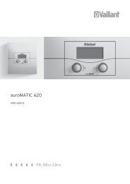
Auf Seite 82 finden Sie eine Übersicht<br />
über die Bedienelemente unter dem<br />
Gerätedeckel (5)<br />
DE GB FR<br />
See page 82 for an overview of the<br />
operating elements located under the<br />
cover panel (5)<br />
En page 82, vous trouverez un<br />
récapitulatif des organes de commande<br />
sous le couvercle de l'appareil (5)<br />
7 5 G 6<br />
H<br />
°C<br />
°C<br />
-1<br />
0<br />
+1<br />
Sa - 15°C<br />
Party Sa - 15°C<br />
Party<br />
-2<br />
+2<br />
-3<br />
+3<br />
<strong>VRC</strong>-VCC<br />
1<br />
2<br />
A B C D E F<br />
<strong>VRC</strong>-VC2_001/0<br />
3
Bedienelemente<br />
1 Tag-Temperaturwähler<br />
zur Einstellung der gewünschten Raumtemperatur.<br />
2 Partytaste/einmaliges Laden des Speichers<br />
zur vorübergehenden Abschaltung des Heizprogramms<br />
oder zum einmaligen Aufheizen des Speicherwassers.<br />
5 Gerätedeckel<br />
6 Display<br />
Das Display gibt Auskunft über Uhrzeit und Wochentag<br />
sowie über Status und Betriebsart des Reglers.<br />
7 Betriebsartenschalter<br />
Stellung „Programm“<br />
In dieser Stellung wird die Raumtemperatur vom<br />
eingegeben Programm geregelt.<br />
Stellung „Heizen“<br />
In dieser Stellung wird die Raumtemperatur ständig nach<br />
der Temperatur geregelt, die am Tag-Temperaturwähler (1)<br />
eingestellt ist.<br />
Stellung „Absenken“ .<br />
In dieser Stellung wird die Raumtemperatur ständig nach<br />
der Absenk-Temperatur (Nacht-Temperatur) geregelt.<br />
☞ Heizkreise:<br />
Tragen Sie hier bitte ein welche Räume über die beiden<br />
Heizkreise (HK) geregelt werden:<br />
HK1:<br />
DE<br />
Display, Übersicht<br />
A Wochentag<br />
B Statusanzeige:<br />
Heizbetrieb Das Gerät befindet sich im Heizbetrieb.<br />
Warmwasser Das Gerät befindet sich im Warmwasserbetrieb.<br />
Party Das Gerät befindet sich im Party-Betrieb<br />
(siehe Seite 10).<br />
Die Anzeige „Heizbetrieb“ wird überdeckt,<br />
weil in dieser Betriebart Heizung und<br />
Warmwasser zur Verfügung stehen.<br />
1x Ladung Das Gerät lädt den Warmwasserspeicher<br />
einmalig auf (siehe Seite 11).<br />
Urlaub Das Ferienprogramm ist aktiv.(s. Seite 36)<br />
Fehlermeldungen (siehe Seite 48)<br />
Störung Das Heizgerät hat eine Störung<br />
Verbindung Die Datenübertragung vom Regler zum<br />
Heizgerät ist gestört.<br />
HK2 VT Sensor Die Verbindung zum Vorlauftemperatursensor<br />
ist gestört.<br />
Wartung Das Heizgerät muß gewartet werden.<br />
C Außentemperatur<br />
D Betriebsart „Absenken“<br />
E Betriebsart „Heizen“<br />
F Betriebsart „Programm“<br />
G Aktuelle Uhrzeit<br />
H Aktuelle Temperatur (Anzeige nur bei Wandmontage)<br />
HK2:<br />
4
DE GB FR<br />
INHALT<br />
Seite<br />
Bedienungsanleitung . . . . . . . .3<br />
1 Geräteübersicht . . . . . . . . . . . . .3,82<br />
1 Gerätebeschreibung . . . . . . . . . . . . .8<br />
2 Bedienung . . . . . . . . . . . . . . . . . . .9<br />
2.1 Raumtemperatur einstellen . . . . . .9<br />
2.2 Lüften . . . . . . . . . . . . . . . . . . .10<br />
2.3 Partyfunktion einschalten . . . . . .10<br />
2.4 Speicher einmalig aufheizen . . . .11<br />
3 Energiespartipps . . . . . . . . . . . . . .12<br />
4 Grundeinstellungen . . . . . . . . . . . .13<br />
4.1 Betriebsart wählen . . . . . . . . . .13<br />
4.2 Landessprache wählen . . . . . . .14<br />
4.3 Uhrzeit/Wochentag einstellen . . .16<br />
4.4 Absenktemperatur einstellen . . . .18<br />
4.5 Heizkurve einstellen . . . . . . . . .20<br />
5 Zeitprogramme . . . . . . . . . . . . . .22<br />
5.1 Werkseitige Einstellungen . . . . . .22<br />
5.2 Übersicht . . . . . . . . . . . . . . . . .24<br />
5.3 Heizkreis wählen . . . . . . . . . . .26<br />
5.4 Heizzeiten einstellen . . . . . . . . .26<br />
5.5 Warmwasserzeiten einstellen . . .34<br />
5.6 Zirkulationszeiten einstellen . . . .35<br />
5.7 Ferienprogramm aktivieren . . . . .36<br />
6 Sonderfunktionen . . . . . . . . . . . . . .38<br />
7 Info-Anzeige . . . . . . . . . . . . . . . . .47<br />
8 Fehlermeldungen . . . . . . . . . . . . . .48<br />
9 Frostschutz . . . . . . . . . . . . . . . . . .49<br />
10 Datenübertragung . . . . . . . . . . . .49<br />
11 Telefonfernschaltung . . . . . . . . . . .50<br />
12 Werkseinstellung . . . . . . . . . . . . .50<br />
13 Werksgarantie . . . . . . . . . . . . . . .51<br />
Montageanleitung . . . . . . . . .53<br />
CONTENTS<br />
Page<br />
Operating instructions . . . . . . .3<br />
1 Thermostat overview . . . . . . . . .3, 82<br />
1 Description of the appliance . . . . . . .8<br />
2 Operation . . . . . . . . . . . . . . . . . . . .9<br />
2.1 Adjusting day temperature . . . . . .9<br />
2.2 Ventilation . . . . . . . . . . . . . . . .10<br />
2.3 Override mode . . . . . . . . . . . . .10<br />
2.4 One-off heating up of tank . . . .11<br />
3 Energy saving hints . . . . . . . . . . . .12<br />
4 Basic settings . . . . . . . . . . . . . . . .13<br />
4.1 Choose operating mode . . . . . .13<br />
4.2 Choose a language . . . . . . . . .14<br />
4.3 Date & time setting . . . . . . . . . .16<br />
4.4 Adjusting night temperature . . . .18<br />
4.5 Setting the heating curve . . . . . .20<br />
5 Heating periods . . . . . . . . . . . . . .22<br />
5.1 Pre-set values . . . . . . . . . . . . . .22<br />
5.2 Overview . . . . . . . . . . . . . . . .24<br />
5.3 Selection of heating circuit . . . . .26<br />
5.4 Programming heating periods . . .26<br />
5.5 Set hot water supply periods . . . .34<br />
5.6 Set circulating periods . . . . . . . .35<br />
5.7 Holiday program . . . . . . . . . . .36<br />
6 Special functions . . . . . . . . . . . . . .38<br />
7 Display of information . . . . . . . . . .47<br />
8 Error messages . . . . . . . . . . . . . . .48<br />
9 Frost Protection . . . . . . . . . . . . . . .49<br />
10 Data transfer . . . . . . . . . . . . . . . .49<br />
11 Remote control . . . . . . . . . . . . . . .50<br />
12 Factory-adjusted elements . . . . . . .50<br />
13 Manufacturer’s Warranty . . . . . . .51<br />
Installation instructions . . . . .53<br />
TABLE DES MATIERES<br />
Page<br />
Mode d'emploi . . . . . . . . . . . .3<br />
1 Vue d’ensemble de l'appareil . . .3, 82<br />
1 Description de l'appareil . . . . . . . . .8<br />
2 Commande . . . . . . . . . . . . . . . . . . .9<br />
2.1 Réglage de la température jour . . .9<br />
2.2 Ventilation/aération local . . . . . .10<br />
2.3 Touche party . . . . . . . . . . . . . .10<br />
2.4 Réchauffage prioritaire du ballon .11<br />
3 Quelques "tuyaux" pour vos<br />
économies d'énergie . . . . . . . . . . .12<br />
4 Pour effectuer les réglages de base .12<br />
4.1 Choix du mode de fonctionnement13<br />
4.2 Choix de la langue . . . . . . . . . .14<br />
4.3 Réglage de l'heure et du jour . . .16<br />
4.4 Réglage de la temp. nocturne . . .18<br />
4.5 Réglage de la courbe de chauffe .20<br />
5 Les périodes de chauffage . . . . . . .22<br />
5.1 Réglages du constructeur . . . . . .22<br />
5.2 Présentation générale . . . . . . . .24<br />
5.3 Choisir le circuit de chauffage . .26<br />
5.4 Programmer les périodes de<br />
chauffage . . . . . . . . . . . . . . . . . .26<br />
5.5 Régler les périodes d’ ECS . . . . .34<br />
5.6 Régler les périodes de recyclage .35<br />
5.7 Programme de congés . . . . . . . .36<br />
6 Fonctions spéciales . . . . . . . . . . . . .38<br />
7 Affichage d'informations . . . . . . . .47<br />
8 Messages d'erreur . . . . . . . . . . . . .48<br />
9 Protection contre le gel . . . . . . . . . .49<br />
10 Transfert de données . . . . . . . . . .49<br />
11 Commande à distance . . . . . . . . .50<br />
12 Réglage usine . . . . . . . . . . . . . . .50<br />
13 Garantie usine . . . . . . . . . . . . . . .51<br />
Instructions de montage . . . . .53<br />
5
Operating elements<br />
1 Day temperature selector<br />
for adjusting to required room temperature.<br />
2 Override/one-off filling of tank<br />
for temporary deactivation of heating program or for oneoff<br />
heating up of tank water (Domestic hot water for VUW<br />
combination boilers only in GB).<br />
5 Device cover<br />
6 Display<br />
The display shows the time and day, along with controller<br />
mode and status information<br />
7 Operating mode switch<br />
”Program“ setting<br />
In this setting, the room temperature is controlled by the<br />
pre-set program.<br />
“Heating“ setting<br />
In this setting, the room temperature is permanently<br />
controlled according to the temperature pre-selected on the<br />
day-temperature selector (1).<br />
“Reduce“ setting<br />
In this setting, the room temperature is permanently<br />
controlled according to the reduced (night) temperature.<br />
☞ Heating circuits:<br />
Please indicate at this point which rooms are to be<br />
controlled via the two heating circuits (HC):<br />
HC1:<br />
HC2:<br />
6<br />
GB<br />
Display, Overview<br />
A Day of the week<br />
B Status indicator<br />
Heating on The appliance is in heating mode.<br />
Hot water The appliance is in hot water mode.<br />
Party The appliance is in party (override) mode<br />
(see page 10).<br />
The “Heating mode“ display message is<br />
blocked-out as heating and hot water are<br />
both available in this operating mode.<br />
DHW Boost The appliance fills the hot-water tank on a<br />
single occasion (see page 11).The<br />
appliance activates the warmstart of the<br />
Aqua-Comfort system. (ecoMax 800 only)<br />
Holiday The holiday program is active (see p. 36).<br />
Error messages (see page 48)<br />
Appl. Fault There is heating system fault.<br />
Conn. Fault Data transfer from the controller to the<br />
heating unit has been interrupted.<br />
CH2 Fault The connection to the flow temperature is<br />
malfunctioning.<br />
Maintenance The heating appliance must be serviced.<br />
(only available with compatible boiler and<br />
electronics; not available in GB)<br />
C Outside temperature<br />
D Operating mode "Night setting”<br />
E Operating mode "Heating”<br />
F Operating mode "Program”<br />
G Actual time<br />
H Actual temperature<br />
(only shown on wall-mounted version)
Organes de commande<br />
1 Sélecteur de température jour<br />
pour le réglage de la température ambiante souhaitée.<br />
2 Touche party/Remplissage exceptionnel du ballon<br />
Pour une déconnexion provisoire du programme de<br />
chauffage ou pour le chauffage unique de l'eau du ballon.<br />
5 Couvercle de l'appareil<br />
6 Ecran<br />
7 Commutateur de mode de fonctionnement<br />
POSITION „Programme“<br />
Dans cette position, la température ambiante est régulée<br />
par le programme entré.<br />
POSITION „Chauffage“<br />
Dans cette position, la température ambiante est réglée<br />
constamment en fonction de celle qui est paramétrée sur le<br />
sélecteur de température jour (1).<br />
POSITION „Abaisser“ .<br />
Dans cette position, la température ambiante est réglée<br />
constamment en fonction de la température de baisse<br />
(température de nuit).<br />
☞ Circuits de chauffage:<br />
Veuillez entrer les pièces qui doivent être régulées par les<br />
deux circuits de chauffage (CC):<br />
CC1:<br />
CC2:<br />
FR<br />
Vue d’ensemble de l'écran<br />
A Jour<br />
B Affichages d’état<br />
Fonct. chauff L'appareil se trouve en mode chauffage.<br />
Chauffe eau L'appareil se trouve en mode chauffe eau.<br />
Party<br />
L'appareil se trouve en mode Party<br />
(voir page 10).<br />
L'affichage „mode chauffage“ est<br />
recouvert, car dans ce mode, le<br />
chauffage et l'eau chaude sont<br />
disponibles.<br />
1x charg. accu L'appareil charge exceptionnellement le<br />
ballon d'eau chaude (voir page 11).<br />
Congés Le programme de congés est actif (voir<br />
page 36)<br />
Messages d'erreur (voir page 48)<br />
Dérangement L'appareil de chauffage a une panne<br />
Défaut Conn° La transmission de données entre le<br />
régulateur et l'appareil de chauffage est<br />
perturbée<br />
Cons adm. CC2 La connexion avec la sonde de<br />
température départ est perturbée.<br />
Maintenance L'appareil de chauffage a besoin d'une<br />
révision.<br />
C Température nocturne réglée<br />
D Mode de fonctionnement "Abaisser"<br />
E Mode de fonctionnement "Chauffer"<br />
F Mode de fonctionnement "Programme"<br />
G Heure actuelle<br />
H Température actuelle<br />
(Affichage uniquement en fixation murale)<br />
7
DE GB FR<br />
1 Gerätebeschreibung<br />
1 Device description<br />
Das Regelgerät ermöglicht die witterungsgeführte<br />
Vorlauftemperatur-Regelung<br />
zweier Heizkreise, eines Brennerkreises<br />
und eines Mischerkreises z. B. für die<br />
Fußbodenheizung. Darüber hinaus kann<br />
es die Warmwasserbereitung und eine<br />
Zirkulationspumpe steuern.<br />
Der Außentemperaturfühler mißt ständig<br />
die aktuelle Außentemperatur. Das Regelgerät<br />
sorgt dafür, dass die eingestellte<br />
Raumtemperatur - bei voll geöffneten<br />
Thermostatventilen - erreicht wird. Hierfür<br />
muß das Heizgerät eine bestimmte Vorlauftemperatur<br />
bereitstellen.<br />
Sobald der Regler angeschlossen ist und<br />
die Uhrzeit eingestellt ist, führt er ein<br />
sinnvolles Heizprogramm durch. Hierfür<br />
muß der Betriebsartenschalter (7, vordere<br />
Klappseite) in der Stellung „Programm“<br />
stehen.<br />
Ausführung mit DCF-Empfänger<br />
Der im Lieferumfang enthaltene DCF-<br />
Empfänger empfängt ein Funkuhr-Zeitsignal<br />
und stellt es Ihrem Regelgerät zur<br />
Verfügung. Die Uhrzeit Ihres Reglers stellt<br />
sich automatisch ein, die Umstellung von<br />
Sommer- auf Winterzeit und umgekehrt<br />
entfällt. Eine manuelle Einstellung der<br />
Uhrzeit ist nur erforderlich, wenn der<br />
Funkempfänger kein Zeitsignal erhält (vgl.<br />
Uhrzeit und Wochentag einstellen).<br />
8<br />
The control device permits weatheractivated<br />
adjustment of the flow<br />
temperature control system, two heating<br />
circuits, one burner circuit and one mixer<br />
circuit (e.g. for under-floor heating). It can<br />
also control the hot water supply and a<br />
circulation pump.<br />
The outdoor-temperature sensor constantly<br />
monitors the exterior temperature. The<br />
control system ensures that the pre-set<br />
room temperature is achieved (with the<br />
thermostat valves fully open). The heating<br />
system must be adjusted to a specific flow<br />
temperature setting in this case.<br />
Once the controller is connected and the<br />
timer set, it efficiently runs the heating<br />
program. Note that the operating mode<br />
switch (7, on front-panel side) should be<br />
set to the “Program“ position.<br />
Configuration with DCF receiver<br />
(not currently available in the UK)<br />
The DCF receiver supplied with the<br />
system captures the timer transmitter<br />
signal, making it available to your control<br />
system. The clock-time of your control<br />
system is set automatically, without any<br />
need to readjust from summer to winter<br />
time or vice versa. Manual adjustment of<br />
the clock is only required if the receiver<br />
fails to capture a timer signal (cf. time<br />
and day adjustment).<br />
1 Description de l'appareil<br />
La régulation permet de réguler la<br />
température départ en fonction de la<br />
température extérieure de deux circuits de<br />
chauffage, d'un circuit brûleur et d'un<br />
circuit vanne de mélange pour chauffage<br />
par le sol par exemple. Il peut commander<br />
en plus la préparation de l'eau<br />
chaude et une pompe de recyclage.<br />
La sonde de température extérieure mesure<br />
constamment la température extérieure.<br />
L'appareil de réglage veille à ce<br />
que la température ambiante paramétrée<br />
soit maintenue – si les vannes thermostatiques<br />
sont ouvertes entièrement. Pour ce<br />
faire, le régulateur doit présenter une<br />
certaine température départ. Dés que le<br />
régulateur est raccordé et que l'heure est<br />
réglée, il exécute un programme de<br />
chauffage approprié. Il faut pour ce faire<br />
que l'interrupteur de sélection de mode<br />
de service (7, clapet frontal) se trouve en<br />
position „Programme“ .<br />
Version avec récepteur DCF (pas pour la France)<br />
Le récepteur DCF fourni dans l'étendue de<br />
fourniture reçoit un signal radio de temps<br />
et le transmet à l'appareil de réglage.<br />
L'horloge de votre régulateur se met automatiquement<br />
à l'heure et le passage<br />
heure d'été heure d'hiver se fait automatiquement.<br />
Un réglage manuel de l'horloge<br />
n'est nécessaire que si le récepteur<br />
radio ne reçoit aucun signal temps (voir<br />
réglage de la date et de l'heure).
2 Bedienung<br />
DE GB FR<br />
Damit Ihr Heizgerät optimal arbeitet,<br />
stellen Sie den Betriebsartenschalter (7,<br />
vordere Klappseite) auf „Programm“ .<br />
2.1 Raumtemperatur einstellen<br />
Mit dem Tag-Temperaturwähler (1,<br />
vordere Klappseite) können Sie die<br />
Raumtemperatur Ihren individuellen<br />
Bedürfnissen anpassen. Position „•“<br />
entspricht einer gewünschten Raumtemperatur<br />
von ca. 20 °C. Jeder Skalenpunkt<br />
bedeutet eine Temperaturveränderung<br />
um etwa 2,5 °C.<br />
● Raumtemperatur „Erhöhen“<br />
Drehen Sie den Tag-Temperaturwähler<br />
nach rechts.<br />
● Raumtemperatur „Senken“<br />
Drehen Sie den Tag-Temperaturwähler<br />
nach links.<br />
Diese Temperaturregelung ist nur aktiv,<br />
wenn die Betriebsart oder<br />
eingestellt ist.<br />
2 Operation<br />
In order to ensure optimum operation of<br />
your heating appliance, set the mode<br />
switch (7, on front-panel side) to<br />
“Program“ .<br />
2.1 Adjusting day temperature<br />
With the day temperature selector<br />
(1,front folding page) you can adjust the<br />
room temperature to individual needs.<br />
Position “•“ is set to approx. 20 °C.<br />
Each point on the scale corresponds to a<br />
temperature-change of about 2.5 °C.<br />
● “To increase“ temperature<br />
Turn the day temperature selector<br />
to the right.<br />
● “To decrease“ temperature<br />
Turn the day temperature selector<br />
to the left.<br />
The temperature can only be adjusted if<br />
the operation mode of the appliance is<br />
set to heating or program .<br />
☞ When the appliance is fitted within<br />
the bolier facia, no additional room<br />
thermostat is required. The overall<br />
temperature of the radiators can be<br />
finely adjusted to meet the heat<br />
requirements of the property using the<br />
temperature selector control in<br />
conjuction with the systems<br />
thermostatic radiator valves<br />
2 Commande<br />
Pour un fonctionnement optimal de<br />
votre appareil de chauffage (7, clapet<br />
frontal) placez l'interrupteur de sélection<br />
de mode sur „Programme“ .<br />
2.1 Réglage de la température jour<br />
Avec le sélecteur de température jour (1,<br />
clapet frontal), vous pouvez adapter la<br />
température ambiante à vos besoins<br />
individuels. La Position „•“ correspond à<br />
une température ambiante de consigne<br />
d’environ 20 °C. Chaque graduation<br />
signifie une modification de température<br />
d'environ 2,5 °C.<br />
● „Augmenter“ la température ambiante<br />
Tournez le sélecteur de température<br />
vers la droite.<br />
● „Abaisser“ la température ambiante<br />
Tournez le sélecteur de température<br />
vers la gauche.<br />
Cette régulation n’est activée que si le<br />
mode de fonctionnement Chauffer ou<br />
Programme est sélectionné.<br />
9
10<br />
DE GB FR<br />
2.2 Lüften<br />
Stellen Sie den Betriebsartenschalter (7,<br />
vordere Klappseite) während des Lüftens<br />
auf Absenken . Damit vermeiden Sie<br />
eine unnötige Heizungseinschaltung.<br />
Nach dem Lüften stellen Sie ihn wieder<br />
zurück in Stellung Programm .<br />
2.3 Partyfunktion einschalten<br />
Ihr Gerät ist mit einer Party-Funktion<br />
ausgestattet. Diese erlaubt es Ihnen, daß<br />
die Heiz- und Warmwasserzeiten über<br />
den nächsten Abschaltpunkt hinaus<br />
fortgesetzt werden. Dies ist z. B. bei<br />
einer Feier sinnvoll, denn der Regler stellt<br />
sich am nächsten Morgen automatisch<br />
zurück auf die Zeitfunktion.<br />
Diese Funktion läßt sich nur aktivieren,<br />
wenn der Betriebsartenschalter auf der<br />
Position steht.<br />
● Drücken Sie die Partytaste (2, vordere<br />
Klappseite).<br />
Im Display erscheint der Schriftzug<br />
Party und neben dem Symbol<br />
erscheint das Symbol .<br />
● Mit dem Start der nächsten<br />
programmierten Heizzeit endet der<br />
Party-betrieb automatisch. Der Regler<br />
arbeitet dann wieder nach den<br />
programmierten Zeiten.<br />
☞ Sie können die Party-Funktion aber<br />
auch dadurch beenden, indem Sie<br />
die Partytaste (2) zweimal drücken.<br />
2.2 Ventilation<br />
During airing switch the operating mode<br />
(7, front folding page) of the appliance<br />
to “Night setting“ to avoid activating<br />
the heating mode. After ventilating,<br />
return it to the Program setting .<br />
2.3 Override mode<br />
Your thermostat is equipped with an<br />
override mode, which enables you to<br />
override the next stopping time for your<br />
heating and hot water. It is therefore not<br />
necessary to change your programmed<br />
standard settings e.g. for a one-off<br />
override. This function can only be<br />
activated if the operating switch is set to<br />
symbol .<br />
● Press the override button (2).<br />
The display says override, and next to<br />
symbol the symbol appears.<br />
●<br />
With the start of the next programmed<br />
heating period the override mode<br />
switches off automatically. The<br />
thermostat returns to the programmed<br />
timings.<br />
☞ The override mode can also be<br />
stopped by pressing the override<br />
button (2) twice.<br />
2.2 Ventilation/aération local<br />
Pendant l’aération, mettez le commutateur<br />
de mode de fonctionnement (7,<br />
clapet frontal)) sur „Abaisser“ .<br />
Vous éviterez ainsi un fonctionnement<br />
inutile de la chaudière.<br />
Après la ventilation, ramenez-le en<br />
position Programme .<br />
2.3 Touche party<br />
Votre appareil est équipé d'une fonction<br />
party. Ceci vous permet de prolonger le<br />
temps de chauffage ou la période d'eau<br />
chaude au-delà du prochain point de<br />
réduction. Cette fonction est utile si vous<br />
organisez une réception ou une soirée,<br />
car vous n'êtes pas alors obligé(e) de<br />
modifier la programmation du régulateur.<br />
Cette fonction ne peut être activée que si<br />
le commutateur de mode de fonctionnement<br />
est en position .<br />
● Appuyez sur la touche party (2).<br />
L'inscription Party apparaît à l'écran<br />
et à côté du symbole apparaît le<br />
symbole .<br />
● Quand la période de chauffage programmable<br />
suivante commence, le<br />
mode party s'arrête automatiquement.<br />
Le régulateur fonctionne ensuite de nouveau<br />
selon les périodes programmées.<br />
☞ Vous pouvez également désactiver la<br />
fonction Party en pressant deux fois la<br />
touche Party (2).
DE GB FR<br />
2.4 Einmalige Ladung für Warmwasser<br />
Ihr Gerät ist mit einer Funktion zur<br />
einmaligen Ladung des Speicherwassers<br />
ausgestattet. Diese erlaubt es Ihnen, den<br />
Warmwasserspeicher sofort aufzuladen<br />
bzw. bei VCW-Geräten den Warmstart<br />
des Aqua-Comfort-Systems zu aktivieren.<br />
Dies ist sinnvoll, wenn Sie z. B. eine<br />
Stunde früher als gewöhnlich eine<br />
grössere Menge Warmwasser benötigen.<br />
Diese Funktion läßt sich nur aktivieren,<br />
wenn der Betriebsartenschalter auf der<br />
Position steht.<br />
● Drücken Sie die Partytaste (2, vordere<br />
Klappseite) zweimal.<br />
Im Display erscheint der Schriftzug<br />
1x Speicherl..<br />
Der Regler fragt das Heizgerät ab, und<br />
schaltet die einmalige Aufladung aus,<br />
sobald das Heizgerät den Speicher<br />
aufgeladen hat.<br />
☞ Ist der Speicher bereits Aufgeladen<br />
wird die einmalige Aufladung nach<br />
45 Minuten abgeschaltet.<br />
☞ Sie können die einmalige Aufladung<br />
auch manuell abschalten, indem Sie<br />
die Partytaste einmal drücken. Der<br />
Schriftzug 1x Speicherl. verschwindet.<br />
2.4 One-off filling for hot water<br />
Your appliance is fitted with a function<br />
that provides for one-off filling with tank<br />
water. This allows you to fill the hot-water<br />
tank immediately or – in the case of<br />
combination boilers such as the ecoMAX 800<br />
series – to activate the warm-start function<br />
of the Aqua-Comfort system. This function<br />
is useful when – for example – a large<br />
quantity of hot water is required an hour<br />
earlier than normal. This function can<br />
only be activated if the operating mode<br />
switch is in the position .<br />
● Press the “party“ override button (2,<br />
front-side of panel) twice.<br />
The display will show the message<br />
1x tank-fill.<br />
The controller automatically shuts down<br />
the one-off filling function, as soon as the<br />
boiler has satisfied this operation.<br />
☞ If the tank is already full, the one-off<br />
filling function is shut down after 45<br />
minutes.<br />
☞ You can also shut down the one-off<br />
filling function manually by pressing<br />
the „override“ button once.<br />
The 1x tank-fill display message will<br />
now disappear.<br />
☞ Tank or cylinder heating is currently<br />
not availible in the UK. This function<br />
is available for the warmstart of the<br />
Aqua-Comfort system on the ecoMAX<br />
800 series only.<br />
2.4 Réchauffage „prioritaire“ du ballon<br />
Votre appareil est doté de la fonction de<br />
réchauffage „prioritaire“ du ballon.<br />
Celle-ci vous permet de réchauffer<br />
rapidement le ballon d'eau chaude et<br />
d’activer le système de Aqua-Comfort sur<br />
les appareils VUW. Cela est<br />
recommandé quand vous avez besoin<br />
d'une plus grande quantité d'eau chaude<br />
que d'habitude une heure plus tôt par<br />
exemple.<br />
Cette fonction ne peut être activée que si<br />
l'interrupteur de sélection de mode est<br />
sur la position .<br />
● Pressez la touche Party (2, clapet<br />
frontal) deux fois.<br />
Sur l'écran apparaît l'inscription<br />
1x remplissage ballon<br />
Le régulateur interroge l'appareil de<br />
chauffage et désactive le réchauffage<br />
exceptionnel dès que l'appareil de<br />
chauffage a rempli le ballon.<br />
☞ Si le ballon est déjà chaud, le<br />
réchauffage exceptionnel s'éteint<br />
après 45 minutes.<br />
☞ Vous pouvez arrêter manuellement le<br />
réchauffage exceptionnel en pressant<br />
une fois la touche Party. L'inscription<br />
„1x charg. accu“ disparaît.<br />
11
3 Energiespartipps<br />
12<br />
DE GB FR<br />
☞ Stellen Sie die Raumtemperatur nur so<br />
hoch ein, daß diese für Ihr Behaglichkeitsempfinden<br />
gerade ausreicht.<br />
Jedes Grad darüber hinaus bedeutet<br />
einen unnötigen Energieverbrauch<br />
von etwa 6 %.<br />
☞ Senken Sie die Raumtemperatur für<br />
die Zeiten Ihrer Nachtruhe und<br />
Abwesenheit ab.<br />
☞ Öffnen Sie während der Heizperiode<br />
das Fenster nur zum Lüften und nicht<br />
zur Temperaturregelung. Eine kurze<br />
Stoßlüftung ist wirkungsvoller und<br />
energiesparender als lange<br />
offenstehende Kippfenster.<br />
☞ Stellen Sie während des Lüftens den<br />
Betriebsartenschalter (s. Geräteübersicht)<br />
auf „Absenken“ (Symbol ).<br />
Damit vermeiden Sie eine unnötige<br />
Heizungseinschaltung.<br />
☞ Lassen Sie in dem Zimmer, in dem<br />
sich Ihr Regelgerät befindet, stets alle<br />
Heizkörperventile voll geöffnet.<br />
☞ Verdecken Sie Ihr Regelgerät nicht<br />
durch Möbel, Vorhänge oder andere<br />
Gegenstände. Es muß die<br />
zirkulierende Raumluft ungehindert<br />
erfassen können.<br />
3 Energy saving hints<br />
☞ Set your room temperature in such a<br />
way that it just reaches your comfort<br />
level. Every degree over and above<br />
that level represents an unnecessary<br />
waste of energy of about 6%.<br />
☞ Reduce your room temperature during<br />
the night and when the dwelling is<br />
not occupied.<br />
☞ When the heating is on open<br />
windows for airing only - not for<br />
regulating the room temperature.<br />
Short periods of airing are more<br />
effective than having a small window<br />
open for long periods.<br />
☞ During airing switch the operating<br />
mode of the appliance to “Night<br />
setting” (Symbol ) to avoid<br />
activating the heating mode.<br />
☞ In the room where the thermostat is<br />
fixed all radiator valves should be left<br />
in the fully open position.<br />
☞ Do not cover your thermostat with<br />
furniture, curtains or other objects. It<br />
must have free access to the air<br />
circulating in the room.<br />
3 Quelques "tuyaux" pour vos<br />
économies d'énergie<br />
☞ Ne réglez la température ambiante<br />
que sur une valeur juste suffisante<br />
pour qu’elle soit agréable. Chaque<br />
degré supérieur à cette limite signifie<br />
une consommation inutile d'énergie<br />
d'environ 6 %.<br />
☞ Abaissez la température ambiante<br />
pour les périodes de repos nocturne<br />
et les périodes d'absence.<br />
☞ Pendant que vous chauffez, n'ouvrez<br />
la fenêtre que pour aérer et non pour<br />
réguler la température. Une brève<br />
aération est plus efficace et économise<br />
davantage d'énergie que<br />
l'ouverture prolongée de fenêtres<br />
entrouvertes.<br />
☞ Pendant l'aération, mettez le commutateur<br />
de mode de fonctionnement<br />
(voir vue d’ensemble de l'appareil)<br />
sur "Abaisser" (symbole ). Vous<br />
éviterez ainsi un fonctionnement<br />
inutile de l’installation de chauffage.<br />
☞ Dans la pièce dans laquelle votre<br />
régulateur est installé, laissez toujours<br />
tous les robinets des radiateurs<br />
complètement ouverts.<br />
☞ Faites en sorte que votre régulateur ne<br />
soit pas recouvert par des meubles,<br />
des rideaux ou d'autres objets. Il doit<br />
pouvoir capter sans aucune entrave<br />
l'air qui circule dans la pièce.
4 Grundeinstellungen<br />
DE GB FR<br />
4.1 Betriebsart wählen<br />
Mit dem Betriebsartenschalter (7, vordere<br />
Klappseite) können Sie die Betriebsweise<br />
Ihrer Anlage einstellen.<br />
● Stellung „Programm“<br />
In dieser Stellung<br />
wird die Raumtemperatur vom<br />
eingegeben Programm geregelt.<br />
Während der Heizzeiten wird die<br />
Temperatur nach der am Tag-<br />
Temperaturwähler (1) eingestellten<br />
Temperatur geregelt, während der Absenkphase<br />
nach der Absenk-<br />
Temperatur.<br />
● Stellung „Heizen“<br />
In dieser Stellung wird die Raumtemperatur<br />
ständig nach der Temperatur<br />
geregelt, die am Tag-Temperaturwähler<br />
(1) eingestellt ist. Im Display<br />
erscheint . Die Programmierung<br />
der Schaltuhr wird nicht<br />
berücksichtigt.<br />
● Stellung „Absenken“ .<br />
In dieser Stellung wird die Raumtemperatur<br />
ständig nach der Absenk-<br />
Temperatur geregelt. Im Display<br />
erscheint . Die Programmierung<br />
der Schaltuhr wird nicht<br />
berücksichtigt. Werkseitig ist die<br />
Absenkung auf 15 °C eingestellt.<br />
4 Basic settings<br />
4.1 Choose the operating mode<br />
The operating mode switch (7, front<br />
folding page) allows you to set the<br />
control for your particular needs. After<br />
a certain time - the length of which<br />
depends on your property and outside<br />
weather conditions - the selected room<br />
temperature will be reached.<br />
● Position “Program“<br />
The room temperature is controlled by<br />
the programmed settings.<br />
During warm-up periods, the<br />
temperature is controlled by means of<br />
the day-temperature selector (1)<br />
setting, and by the reduction<br />
temperature during the reduction<br />
●<br />
●<br />
phase.<br />
Position “Heating”<br />
The room temperature is constantly<br />
adjusted to the set day temperature.<br />
The display shows .<br />
Any programming is overridden.<br />
Position “Night setting”<br />
With this setting the room temperature<br />
is constantly set at the night<br />
temperature. The display shows .<br />
Any programming is<br />
overridden. The factory setting for this<br />
mode is 15 °C.<br />
4 Les réglages de base<br />
4.1 Choisir le mode de fonctionnement<br />
Avec le commutateur de modes de fonctionnement<br />
(7, clapet frontal), vous<br />
pouvez adapter le mode de fonctionnement<br />
de votre installation à vos besoins.<br />
La température ambiante souhaitée est<br />
atteinte progressivement, la durée<br />
nécessaire dépendant de votre bâtiment<br />
et de la température extérieure.<br />
●<br />
●<br />
●<br />
Position "Programme"<br />
Avec ce réglage, la température<br />
ambiante est réglée en fonction des<br />
données programmées. Pendant les<br />
périodes de chauffage, la température<br />
est régulée selon la température paramétrée<br />
sur le sélecteur de température<br />
jour (1), pendant la phase de baisse<br />
d'après la température d’abaissement.<br />
Position "Chauffage"<br />
Avec ce réglage, la température<br />
ambiante est constamment réglée en<br />
fonction de la température définie<br />
avec le sélecteur de température jour.<br />
Le symbole apparaît à l'écran. La<br />
programmation de la minuterie n'est<br />
pas prise en considération.<br />
Position "Abaissement"<br />
Avec ce réglage, la température de la<br />
pièce est constamment réglée en fonction<br />
de la température nocturne. Le<br />
symbole apparaît à l'écran. La programmation<br />
de la minuterie n'est pas<br />
prise en considération. L'abaissement<br />
est réglé sur 15 °C par le constructeur.<br />
13
4<br />
3<br />
2<br />
1<br />
<br />
<br />
<strong>VRC</strong>_VC2_009/0<br />
4<br />
3<br />
2<br />
1<br />
<br />
<br />
<strong>VRC</strong>_VC2_009/0<br />
4<br />
3<br />
2<br />
1<br />
<br />
<br />
<strong>VRC</strong>_VC2_009/0<br />
14
DE GB FR<br />
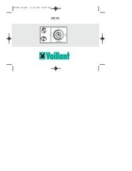
4.2 Landessprache wählen<br />
☞ Der Regler wird werkseitig in der<br />
Landessprache „Deutsch“ bzw.<br />
„Spanisch“ ausgeliefert. Die<br />
Einstellung Ihrer Landessprache hat Ihr<br />
Installateur bei der Erstinbetriebnahme<br />
vorgenommen. Im Normalfall ist keine<br />
Änderung mehr erforderlich. Wollen<br />
Sie die Einstellung doch einmal<br />
ändern gehen Sie bitte wie folgt vor:<br />
● Klappen Sie den Gerätedeckel (5)<br />
auf.<br />
● Drehen Sie den Schalter (4) auf das<br />
Symbol .<br />
Im Display erscheint die<br />
„internationale Länderkennung“ und<br />
der Schriftzug „Sprache“ in der<br />
jeweiligen Landessprache.<br />
● Drehen Sie nun den Einsteller (3)<br />
nach rechts oder links und wählen Sie<br />
die gewünschte Sprache.<br />
● Schließen Sie den Gerätedeckel (5).<br />
☞ Die Einstellung wird automatisch<br />
gespeichert. Sie müssen diese also<br />
nicht mehr bestätigen.<br />
4.2 Choose a language<br />
☞ The control is pre-set by the factory<br />
to "German”. The re-setting to the<br />
language required (English, French,<br />
…) has already been done by your<br />
installer when the control was<br />
commissioned. Normally it is not<br />
necessary to re-set anything again.<br />
Should you wish to re-set the<br />
language yourself please proceed as<br />
follows:<br />
● Open the control cover (5).<br />
● Turn the switch (4) to symbol .<br />
The display shows the flashing writing<br />
“International Country-Identification”<br />
and the text message “Language“ in<br />
the corresponding language.<br />
● Now turn the setting switch (3) left or<br />
right and choose die appropriate<br />
language.<br />
● Close the control cover (5).<br />
☞ Your setting is automatically saved.<br />
You do not need to confirm your<br />
choice.<br />
4.2 Choix de la langue<br />
☞ Le régulateur est livré avec réglage<br />
sur la langue allemande. C'est votre<br />
installateur qui a effectué le réglage<br />
sur la langue requise (anglais,<br />
français, ...) lors de la première mise<br />
en service. Normalement, aucune<br />
modification n'est plus nécessaire.<br />
Si vous désirez cependant modifier le<br />
réglage, veuillez procéder comme<br />
suit:<br />
● Ouvrez le couvercle (5).<br />
● Placez le commutateur (4) sur le<br />
symbole .<br />
L'inscription „Désignation internationale<br />
des pays“ et l'inscription<br />
„Langue“ dans la langue nationale<br />
apparaît à l'écran et clignote.<br />
● Tournez maintenant le sélecteur (3)<br />
vers la droite ou vers la gauche et<br />
choisissez la langue.<br />
☞ Le réglage est mémorisé<br />
automatiquement. Vous n'êtes donc<br />
plus obligé(e) de le confirmer de<br />
nouveau.<br />
15
4<br />
3<br />
3<br />
3<br />
2<br />
1<br />
<br />
<br />
<br />
<br />
<br />
<br />
<br />
<br />
<strong>VRC</strong>-VC2_011/0<br />
4<br />
3<br />
3<br />
3<br />
2<br />
1<br />
<br />
<br />
<br />
<br />
<br />
<br />
<br />
<br />
<strong>VRC</strong>_VC2_011/0<br />
4<br />
3<br />
3<br />
3<br />
2<br />
1<br />
<br />
<br />
<br />
<br />
<br />
<br />
<br />
<br />
<strong>VRC</strong>_VC2_011/0<br />
16
DE GB FR<br />
4.3 Uhrzeit und Wochentag einstellen<br />
Wenn Ihr Gerät ist mit einem DCF-<br />
Empfänger ausgestattet ist, so<br />
synchronisiert dieser die Uhrzeit mit dem<br />
offiziellen deutschen Zeitsignal, wenn der<br />
Empfang möglich ist. Die Uhrzeit Ihres<br />
Regelgerätes stellt sich automatisch ein.<br />
Das gilt auch für die Umstellung von<br />
Sommer- auf Winterzeit und umgekehrt.<br />
Müssen Sie Uhrzeit oder Wochentag<br />
jedoch einmal ändern gehen Sie bitte<br />
wie folgt vor:<br />
● Klappen Sie den Gerätedeckel (5)<br />
auf.<br />
● Drehen Sie den Schalter (4) auf das<br />
Symbol .<br />
Im Display erscheint eine blinkende<br />
Uhrzeit und der Schriftzug „Uhrzeit“.<br />
● Drehen Sie nun den Einsteller (3)<br />
- nach links, um die Uhrzeit zurückzustellen<br />
- nach rechts, um die Uhrzeit vorzustellen.<br />
● Drücken Sie den Einsteller (3).<br />
Im Display erscheint ein blinkender<br />
Wochentag mit dem Schriftzug<br />
„Wochentag“.<br />
● Nehmen Sie die Einstellung wie bei<br />
der Uhrzeit beschrieben für den<br />
Wochentag vor.<br />
☞ Uhrzeit und Datum werden automatisch<br />
gespeichert. Sie müssen die<br />
neuen Werte also nicht bestätigen.<br />
4.2 Date and time setting<br />
(The DCF receiver system is not currently<br />
available in the UK)<br />
If your control is fitted with a DCF<br />
receiver, the time for your thermostat will<br />
automatically adjusted and synchronised<br />
with the German standard time - if the<br />
signals can be received. This is also the<br />
case for changing from summer to winter<br />
time or vice versa.<br />
Should you, however, need to adjust<br />
either time or date manually please<br />
proceed as follows:<br />
● Open the control cover (5)<br />
● Turn switch (4) to symbol .<br />
The display shows a flashing time and<br />
the word “Time“ next to it.<br />
● Now turn the knob (3)<br />
- to the left to adjust time backwards<br />
- to the right to adjust time forward<br />
● Press the knob (3)<br />
The display shows a flashing day with<br />
the wording “Day“.<br />
● Follow the same steps as for time also<br />
for day adjusting.<br />
☞ The new time and date are<br />
automatically saved, there is no need<br />
to confirm the new setting.<br />
4.3 Réglage de l'heure et du jour<br />
Si votre appareil est équipé d'un récepteur<br />
DCF (pas en France), l’heure de<br />
votre régulateur est règlé automatiquement.<br />
Il est synchronisé avec l'heure de<br />
l'horloge officielle allemande quand la<br />
réception est possible. Ceci vaut<br />
également pour le passage de l'heure<br />
d'été à l'heure d'hiver et inversement.<br />
Si vous devez modifier l'heure ou le jour,<br />
veuillez procéder comme suit:<br />
● Ouvrez le couvercle de l'appareil (5).<br />
● Placez le commutateur (4) sur le<br />
symbole .<br />
A l'écran, l'inscription "Heure" et<br />
l'heure apparaissent ; l'heure<br />
clignote.<br />
● Tournez maintenant le sélecteur (3)<br />
- vers la gauche, pour retarder<br />
l'horloge<br />
- vers la droite, pour faire avancer<br />
l'horloge.<br />
● Appuyez sur le sélecteur (3).<br />
A l'écran, l'inscription "Jour"<br />
apparaît et le nom d'un des jours de<br />
la semaine clignote.<br />
● Effectuez le réglage du jour de la<br />
semaine comme celui de l'heure.<br />
☞ L'heure et le jour sont mémorisés<br />
automatiquement. Vous n'êtes donc<br />
pas obligé(e) de confirmer les<br />
nouvelles valeurs.<br />
17
4<br />
°C 3 °C<br />
3<br />
°C<br />
2<br />
1<br />
<br />
<br />
<br />
<br />
<br />
<br />
<strong>VRC</strong>-VC2_008/0<br />
4<br />
°C 3 °C<br />
3<br />
°C<br />
2<br />
1<br />
<br />
<br />
<br />
<br />
<br />
<br />
<strong>VRC</strong>-VC2_008/0<br />
4<br />
°C 3 °C<br />
3<br />
°C<br />
2<br />
1<br />
<br />
<br />
<br />
<br />
<br />
<br />
18<br />
<strong>VRC</strong>-VC2_008/0
DE GB FR<br />
4.4 Absenktemperatur einstellen<br />
● Klappen Sie den Gerätedeckel (5) auf.<br />
● Drehen Sie den Funktionsartenschalter<br />
(4) auf das Symbol .<br />
Im Display erscheint eine blinkende 15<br />
und die Anzeige „HK 1“ und<br />
„Absenktemp“.<br />
● Drehen Sie nun den Einsteller (3)<br />
- nach links, um die Absenktemperatur<br />
zu verringern<br />
- nach rechts, um die Absenktemperatur<br />
zu erhöhen.<br />
☞ Der Wert wird automatisch<br />
gespeichert. Sie müssen den neuen<br />
Wert also nicht bestätigen.<br />
☞ Die Absenk-Temperatur kann in einem<br />
Bereich von 5 °C bis 20 °C verstellt<br />
werden.<br />
Die Einstellung der Absenktemperatur<br />
auf 0°C empfiehlt sich nur bei<br />
längerer Abwesenheit, da sie nur den<br />
Frostschutz der Anlage sicherstellt.<br />
● Zur Einstellung der Absenk-Temperatur<br />
für den Heizkreis 2 drücken Sie auf<br />
den „Einsteller“ (3), um den Heizkreis<br />
2 auszuwählen.<br />
Im Display erscheint eine blinkende 15<br />
und die Anzeige „HK 2“ und<br />
„Absenktemp“.<br />
Stellen Sie die Absenk-Temperatur ein<br />
wie oben beschrieben.<br />
4.4 Adjusting night temperature<br />
● Open the control cover (5)<br />
● Turn switch (4) to symbol<br />
The display shows a flashing 15 and<br />
the words “HC1“ and “Min. Temp.“<br />
next to it.<br />
● Now turn the knob (3)<br />
- to the left to decrease the<br />
temperature<br />
- to the right to increase the<br />
temperature.<br />
☞ The new temperature is automatically<br />
saved, there is no need to confirm the<br />
new setting.<br />
☞ The reduction temperature can<br />
be adjusted within a range of<br />
5 °C to 20 °C.<br />
The reduction temperature should only<br />
be set to 0 °C during long absences,<br />
as it ensures only that the system will<br />
be protected from frost.<br />
● To set the reduction temperature for<br />
heating circuit 2, press the “Adjuster“<br />
(3) to select heating circuit 2.<br />
The display shows a flashing 15 and<br />
the words “HC 2“ and “Min. Temp.“<br />
next to it.<br />
Set the reduction temperature as<br />
described above.<br />
4.4 Régler la température d’abaissement<br />
● Ouvrez le couvercle de l'appareil (5).<br />
● Placez le commutateur (4) sur le<br />
symbole .<br />
Le nombre 15 et les incriptions „CC 1“<br />
et „Abaissement“ apparaisent à<br />
l’écran et le 15 clignote.<br />
● Tournez maintenant l’ajusteur (3)<br />
- vers la gauche, pour réduire la<br />
température d’abaissement<br />
- vers la droite, pour faire augmenter<br />
la température d’abaissement<br />
☞ La valeur est mémorisée<br />
automatiquement. Vous n'êtes donc<br />
pas obligé(e) de confirmer les<br />
nouvelles valeurs.<br />
☞ La température d’abaissement peut<br />
être réglée dans une plage comprise<br />
entre 5 °C et 20 °C. Le paramétrage<br />
de la température d’abaissement à<br />
0 °C est recommandé uniquement en<br />
cas d'absence prolongée afin de<br />
protéger l'installation du gel.<br />
● Pour le paramétrage de la température<br />
d’abaissement du circuit de<br />
chauffage 2, pressez le sélecteur (3),<br />
afin de sélectionner le circuit de<br />
chauffage 2.<br />
Le nombre 15 et les incriptions „CC 2“<br />
et „Abaissement“ apparaisent à<br />
l’écran et le 15 clignote.<br />
Paramétrez la température d’abaissement<br />
tel que décrit ci-dessus.<br />
19
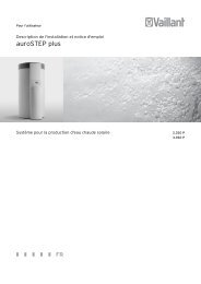
Vorlauftemperatur<br />
Advance flow temp.<br />
Température aller<br />
Heizkurven<br />
Heating curves<br />
Courbes de chauffage<br />
4<br />
3<br />
90<br />
4.0<br />
3.5<br />
3.0<br />
2.5<br />
2.0<br />
2<br />
1<br />
80<br />
1.5<br />
70<br />
60<br />
1.2<br />
1.0<br />
<br />
<br />
<br />
<br />
50<br />
0.6<br />
3<br />
3<br />
40<br />
30<br />
0.2<br />
20<br />
20 15 10 5 0 – 5 – 10 – 15 – 20<br />
Außentemperatur<br />
Outside temperature<br />
Température extérieure<br />
<strong>VRC</strong>-VC2_019/0<br />
<br />
<br />
<br />
<br />
<strong>VRC</strong>-VC2_010/1<br />
4<br />
3<br />
4<br />
3<br />
2<br />
2<br />
1<br />
1<br />
<br />
<br />
<br />
<br />
<br />
<br />
<br />
<br />
3<br />
3<br />
3<br />
3<br />
<br />
<br />
<br />
<br />
<br />
<br />
<br />
<br />
<strong>VRC</strong>-VC2_010/1<br />
<strong>VRC</strong>-VC2_010/1<br />
20
DE GB FR<br />
4.5 Heizkurve einstellen<br />
Die Heizkurve beschreibt die Abhänigkeit<br />
der erforderlichen Vorlauftemperatur<br />
von der Außentemperatur.<br />
Die Einstellung der Heizkurve hat Ihr<br />
Installateur bei der Erstinbetriebnahme<br />
vorgenommen. Im Normalfall ist keine<br />
Änderung mehr erforderlich.<br />
Falls bei niedrigen Außentemperaturen<br />
trotz voll geöffneter Thermostatventile und<br />
geschlossener Türen und Fenster die gewünschte<br />
Raumtemperatur nicht erreicht<br />
wird, sollten Sie die Heizkurve<br />
korrigieren. Gehen Sie bitte wie folgt<br />
vor:<br />
● Klappen Sie den Gerätedeckel (5)<br />
auf.<br />
● Drehen Sie den Schalter (4) auf das<br />
Symbol .<br />
Im Display erscheint eine blinkende<br />
Zahl und der Schriftzug „Hz-Kurve“<br />
und „HK 1“.<br />
● Wählen Sie den Heizkreis aus<br />
Heizkreis 1: ist bereits aktiv<br />
für Heizkreis 2 Einsteller (3) drücken.<br />
● Drehen Sie nun den Einsteller (3)<br />
- nach links, um den Wert zu<br />
verringern<br />
- nach rechts, um den Wert zu<br />
vergrößern.<br />
☞ Der neue Wert wird automatisch<br />
gespeichert. Sie müssen ihn also nicht<br />
mehr bestätigen.<br />
4.5 Setting the heating curve<br />
☞ The heating curve has been set by<br />
your installer when he commissioned<br />
your thermostat. Normally it is not<br />
necessary to change this setting.<br />
Should you, however, need to re-set<br />
the heating curve, proceed as follows:<br />
● Open the control cover (5).<br />
● Turn switch (4) to symbol .<br />
The display shows a flashing number<br />
and the word “Heat. Curve“ and<br />
„HC1“.<br />
● Turn knob (3)<br />
- to the left, to decrease the value<br />
- to the right to increase the value<br />
☞ The heating curve must be set correctly<br />
to match the design requirements of the<br />
heating system. e.g. 80°C flow, 60°C<br />
return at -1°C outside temperature, the<br />
heat curve parameter should be set<br />
around 2.6 to 2.8 to satisfy the<br />
heating demand.<br />
● To set the heating curve for heating<br />
circuit 2, press the “Adjuster“ (3) to<br />
select heating circuit 2.<br />
The display shows a flashing 15 and<br />
the words “HC 2“ and “Heat. Curve“<br />
next to it.<br />
Set the heating curve as described<br />
above.<br />
☞ The new value is saved automatically,<br />
there is no need to confirm the new<br />
setting.<br />
4.5 Réglage de la courbe de chauffage<br />
☞ Le réglage de la courbe de chauffage<br />
a été effectué par votre installateur<br />
lors de la première mise en service.<br />
Normalement, aucune modification<br />
n'est plus nécessaire. Si vous désirez<br />
cependant modifier le réglage de la<br />
courbe de chauffage, veuillez<br />
procéder comme suit:<br />
● Ouvrez le couvercle (5) de l'appareil.<br />
● Placez le commutateur (4) sur le<br />
symbol .<br />
Un nombre qui clignote et l'inscription<br />
"Courbe chauf" et „CC1“<br />
apparaissent à l'écran.<br />
● Tournez maintenant le sélecteur (3)<br />
- vers la gauche, pour réduire la<br />
valeur,<br />
- vers la droite, pour faire augmenter<br />
la valeur.<br />
● Pour le paramétrage de la courbe de<br />
chauffage du circuit 2, pressez le<br />
sélecteur (3), afin de sélectionner le<br />
circuit de chauffage 2.<br />
Le nombre 15 et les incriptions „CC 2“<br />
et „Abaissement“ apparaisent à<br />
l’écran et le 15 clignote.<br />
Paramétrez la courbe de chauffagel<br />
que décrit ci-dessus.<br />
☞ La nouvelle valeur est mémorisée automatiquement.<br />
Vous n'êtes donc plus<br />
obligé(e) de la confirmer de nouveau.<br />
21
HK1 HK2 Warmwasser- Zirkulations- HK1 HK2 HK1 HK2<br />
Anzeige Heizzeiten Heizzeiten zeiten zeiten Nachttemp. Nachttemp. Heizkurve Heizkurve<br />
Display HC1 Heating HC2 Heating Hot water Circulation HC1 Night HC2 Night HC1 Heating HC1 Heating<br />
Affichage settings settings settings settings temperature temperature curve curve<br />
CC1 Périodes CC2 Périodes Périodes Périodes CC1Température CC2Température CC1 Courbe CC2 Courbe<br />
de chauffage de chauffage E.C.S. de circulation d’abaissement d’abaissement de chauffage de chauffage<br />
Allgemein<br />
General 15°C 15°C 1,2 1,2<br />
En général<br />
Mo bis Fr<br />
Mo - Fr 06:00 - 22:00 06:00 - 22:00 06:00 - 22:00 06:00 - 22:00<br />
Du lu au ve<br />
Sa<br />
Sa 07:30 - 23:30 07:30 - 23:30 07:30 - 23:30 07:30 - 23:30<br />
Sa<br />
So<br />
Su 07:30 - 22:00 07:30 - 22:00 07:30 - 22:00 07:30 - 22:00<br />
Di<br />
22
DE GB FR<br />
5 Zeitprogramme einstellen<br />
Das Regelgerät kann zwei Heizkreise<br />
steuern.<br />
Darüber hinaus kann die Warmwasserbereitung<br />
und die Zirkulationspumpe<br />
gesteuert werden.<br />
5.1 Werkseitige Einstellungen<br />
Werkseitig sind sinnvolle Zeitprogramme<br />
für die einzelnen Kreise voreingestellt.<br />
Der nebenstehenden Tabelle können Sie<br />
die werkseitigen Einstellungen<br />
entnehmen.<br />
Sind Sie mit den Einstellungen zufrieden<br />
brauchen Sie keine weiteren Änderungen<br />
mehr vorzunehmen.<br />
Wollen Sie die eine oder andere Einstellung<br />
ändern, gehen Sie bitte in das<br />
entsprechende Kapitel der Bedienungsanleitung.<br />
Tipp!<br />
Bei geänderten Einstellungen ist es<br />
sinnvoll, die Daten in die freien Felder<br />
der nebenstehenden Tabelle einzutragen.<br />
5 Setting the timer programs<br />
The system can control two heating<br />
circuits – plus the hot-water supply and<br />
the circulation pump.<br />
5.1 Pre-set values<br />
The timer programs for the individual<br />
circuits are factory adjusted to normal<br />
default settings. The opposite table shows<br />
all values which already have been preset.<br />
If you are happy with those settings<br />
there is no need for any further action.<br />
Should you wish to change the one or<br />
other settings please look at the<br />
respective chapter in the instructions.<br />
HINT !<br />
You might find it helpful to enter any<br />
changed settings into the empty<br />
boxes of the table opposite.<br />
5 Paramétrage des programmes<br />
temps<br />
La régulation peut commander deux<br />
circuits de chauffage.<br />
Il peut en outre piloter la préparation<br />
d'eau chaude et la pompe de recyclage.<br />
5.1 Réglages du constructeur<br />
Des programmes temps recommandés<br />
pour chacun des circuits sont préréglés<br />
en usine.<br />
Le tableau ci-contre donne les réglages<br />
du constructeur.<br />
Si ces réglages vous conviennent, aucune<br />
modification n’est nécessaire.<br />
Si vous désirez faire telle ou telle<br />
modification, veuillez vous reporter au<br />
chapitre correspondant des instructions<br />
de service.<br />
UN "TUYAU"!<br />
En cas de modification des réglages, il<br />
peut être utile de noter les diverses<br />
données et de les inscrire dans les cases<br />
vides du tableau ci-contre<br />
23
<strong>VRC</strong>_VC_135/1<br />
<br />
<br />
<br />
<br />
<br />
<br />
<br />
<br />
<br />
<strong>VRC</strong>_VC_135/1<br />
<br />
<br />
<br />
<br />
<br />
<br />
<br />
<br />
<br />
<strong>VRC</strong>_VC_135/1<br />
24
DE GB FR<br />
5.2 Übersicht Zeitprogramme<br />
Für jeden Heizkreis, sowie für die Warmwasserbereitung<br />
können Sie bis zu drei<br />
Heizzeiten pro Tag programmieren, die<br />
in sogenannten Fenstern angezeigt<br />
werden, z. B.<br />
Fenster 1:<br />
Heizung an: 5:30<br />
Heizung aus: 8:00<br />
Fenster 2:<br />
Heizung an: 11:30<br />
Heizung aus: 13:45<br />
Fenster 3:<br />
Heizung an: 18:00<br />
Heizung aus: 22:30<br />
Die Heizzeiten können Sie für die Blöcke<br />
Montag bis Sonntag (Mo-So)<br />
Montag bis Freitag (Mo-Fr)<br />
Samstag bis Sonntag (Sa-So)<br />
oder für einzelne Tage (Mo, Di, Mi, Do,<br />
Fr, Sa, So) eingeben.<br />
Die Ansteuerung der Zirkulationspumpe<br />
erfolgt ebenfalls über maximal drei<br />
Zeitfenster pro Tag.<br />
5.2 Overview<br />
You can program each heating circuit<br />
and the hot water supply to activate up<br />
to three times a day, using a “windows“-<br />
type system. For example,<br />
Programme 1:<br />
Heating start: 5:30<br />
Heating stop: 8:00<br />
Programme 2:<br />
Heating start: 11:30<br />
Heating stop: 13:45<br />
Programme 3:<br />
Heating start: 18:00<br />
Heating stop: 22:30<br />
These heating periods can be entered for<br />
sets of days, like<br />
Monday to Sunday<br />
Monday to Friday<br />
Saturday to Sunday<br />
or individual days (Mo, Tu, We, Th, Fr,<br />
Sa, Su).<br />
The activation of the circulation pump is<br />
also carried out via a maximum of three<br />
“time windows“ per day.<br />
☞ The secondary circulation pump<br />
function requires a additional PCB<br />
accessory for the UK market. This is<br />
available from <strong>Vaillant</strong>.<br />
5.2 Présentation générale<br />
Pour chaque circuit de chauffage ainsi<br />
que pour la préparation d'eau chaude,<br />
vous pouvez programmer jusqu'à trois<br />
périodes de chauffage par jour qui seront<br />
affichées dans lesdites fenêtres, par ex.<br />
Fenêtre 1:<br />
Mise en marche du chauffage: 5:30<br />
Arrêt du chauffage: 8:00<br />
Fenêtre 2:<br />
Mise en marche du chauffage: 11:30<br />
Arrêt du chauffage: 13:45<br />
Fenêtre 3:<br />
Mise en marche du chauffage: 18:00<br />
Arrêt du chauffage: 22:30<br />
Vous pouvez définir ces périodes de<br />
chauffage pour les blocs<br />
Lundi à dimanche (Lu - Di)<br />
Lundi à vendredi (Lu - Ve)<br />
Samedi à dimanche (Sa - Di)<br />
ou pour des jours isolés (Lu, Ma, Me, Je,<br />
Ve, Sa, Di).<br />
Le pilotage de la pompe de recyclage<br />
s'effectue également par trois fenêtres de<br />
temps maximum par jour.<br />
25
4<br />
2<br />
1<br />
<br />
<br />
<br />
<strong>VRC</strong>-VC2_013/0<br />
4<br />
2<br />
1<br />
<br />
<br />
<br />
<strong>VRC</strong>-VC2_013/0<br />
4<br />
2<br />
1<br />
<br />
<br />
<br />
<strong>VRC</strong>-VC2_013/0<br />
26
DE GB FR<br />
5.3 Heizkreis wählen<br />
● Klappen Sie den Gerätedeckel (5)<br />
auf.<br />
● Drehen Sie den Schalter (4) auf<br />
1<br />
2<br />
für Heizkreis 1 bzw.<br />
für Heizkreis 2.<br />
Im Display erscheint blinkend<br />
„Fenster 1“ mit den vorgegebenen<br />
Wochentagen, z. B. Montag bis<br />
Freitag.<br />
5.4 Heizzeiten einstellen<br />
Das Einstellen der Heizzeiten läßt sich<br />
am besten anhand eines Beispiels<br />
erklären. Spielen Sie das Beispiel einmal<br />
durch (es dauert keine zehn Minuten)<br />
und Sie werden sehen wie einfach diese<br />
Programmierung ist.<br />
Die Heizung soll für Heizkreis 1 zu<br />
folgenden Zeiten in Betrieb gehen:<br />
von Montags bis Freitags:<br />
Heizung an: 5:30<br />
Heizung aus: 9:00<br />
Heizung an: 17:00<br />
Heizung aus: 22:00<br />
von Samstags bis Sonntags:<br />
Heizung an: 8:00<br />
Heizung aus: 23:00<br />
5.3 Selection of heating circuit<br />
Proceed as follows:<br />
● Open the control cover (5).<br />
●<br />
Turn switch (4) to symbol<br />
1<br />
2<br />
for heating circuit 1 or<br />
for heating circuit 2.<br />
The display shows a flashing<br />
“Programme 1“ with the chosen days,<br />
e.g. Monday - Friday.<br />
5.4 Programming heating periods<br />
The programming of heating periods is<br />
best explained with an example. Try the<br />
example setting (it won’t take more than<br />
10 minutes) and you will see how easy<br />
the programming is.<br />
Heating should come on during the<br />
following times:<br />
Monday – Friday<br />
Heating on: 05.30<br />
Heating off: 09.00<br />
Heating on: 17.00<br />
Heating off: 22.00<br />
Saturday - Sunday<br />
Heating on: 08.00<br />
Heating off: 23.00<br />
5.3 Sélection des circuits de chauffage<br />
Procédez comme suit:<br />
● Ouvrez le couvercle de l'appareil (5).<br />
●<br />
Tournez le commutateur (4) sur le<br />
symbole:<br />
1<br />
pour le circuit de chauffage 1 ou<br />
2<br />
pour le circuit de chauffage 2.<br />
A l'écran, l'inscription "Fenêtre<br />
hor. 1" apparaît en clignotant avec<br />
les jours de la semaine prédéfinis,<br />
par exemple lundi à vendredi.<br />
5.4 Programmation des périodes de<br />
chauffage<br />
Le mieux est d'expliquer la programmation<br />
des périodes de chauffage à<br />
l’aide d’un exemple. Procédez une seule<br />
fois en suivant la description (cela vous<br />
demandera moins de dix minutes) et vous<br />
constaterez vous-même la simplicité de<br />
cette programmation.<br />
Le chauffage doit être activé pendant les<br />
périodes suivantes:<br />
du lundi au vendredi:<br />
Mise en marche du chauffage: 5:30<br />
Arrêt du chauffage: 9:00<br />
Mise en marche du chauffage: 17:00<br />
Arrêt du chauffage: 22:00<br />
du samedi au dimanche:<br />
Mise en marche du chauffage: 8:00<br />
Arrêt du chauffage: 23:00<br />
27
3 3<br />
3 3<br />
<br />
<br />
<br />
<br />
<br />
<br />
<br />
<br />
<br />
<br />
<br />
<br />
<strong>VRC</strong>-VC2_015/0<br />
3 3<br />
3 3<br />
<br />
<br />
<br />
<br />
<br />
<br />
<br />
<br />
<br />
<br />
<br />
<br />
<strong>VRC</strong>-VC2_015/0<br />
3 3<br />
3 3<br />
<br />
<br />
<br />
<br />
<br />
<br />
<br />
<br />
<br />
<br />
<br />
<br />
<strong>VRC</strong>-VC2_015/0<br />
28
DE GB FR<br />
5.4 Heizzeiten einstellen (Fortsetzung)<br />
●<br />
●<br />
●<br />
●<br />
Drücken Sie den Einsteller (3) bis die<br />
linke Uhrzeit blinkt.<br />
Im Display steht in der Klarschriftzeile<br />
„Beginn 1“, d. h. Sie bestimmen den<br />
Einschaltzeitpunkt der Heizung für das<br />
1. Schaltfenster.<br />
Drehen Sie den Einsteller (3) nach<br />
links bis im Display oben links „5:30“<br />
erscheint.<br />
Drücken Sie den Einsteller (3) bis die<br />
rechte Uhrzeit blinkt.<br />
Im Display steht in der Klarschriftzeile<br />
„Ende 1“, d. h. Sie bestimmen den<br />
Ausschaltzeitpunkt der Heizung für<br />
das 1. Schaltfenster.<br />
Drehen Sie den Einsteller (3) nach<br />
rechts bis im Display oben rechts<br />
„9:00“ erscheint.<br />
☞ Die Werte werden automatisch<br />
gespeichert. Sie müssen die neuen<br />
Eingaben also nicht mehr bestätigen.<br />
Damit haben Sie das erste Zeitfenster<br />
schon programmiert.<br />
5.4 Programming heating periods (cont.)<br />
● Press the button (3) until the time on<br />
the left starts flashing.<br />
The display shows “On Time 1”,<br />
which means you are setting the<br />
starting time for heating period 1.<br />
● Turn button (3) to the left until “5:30“<br />
appears on the upper left of the<br />
display.<br />
● Press button (3) until the time on the<br />
right starts flashing.<br />
● The display shows “Off Time 1”,<br />
which means you are setting the off<br />
time for heating for period 1.<br />
● Turn button (3) to the right until<br />
“9:00“ appears on the upper right of<br />
the display.<br />
☞ All new settings are automatically<br />
saved, there is no need to confirm<br />
your settings.<br />
Heating period 1 has now been<br />
programmed.<br />
5.4 Programmation des périodes de<br />
chauffage (suite)<br />
● Appuyez sur le sélecteur (3) jusqu'à<br />
ce que l'heure de gauche clignote.<br />
A l'écran, "Début 1" apparaît dans la<br />
ligne de texte, c'est-à-dire que vous<br />
déterminez le moment de mise en<br />
marche du chauffage pour la<br />
première fenêtre de commutation.<br />
● Tournez le sélecteur (3) vers la gauche<br />
jusqu'à ce que "5:30" apparaisse en<br />
haut à gauche.<br />
● Appuyez sur le sélecteur (3) jusqu'à<br />
ce que l'heure de droite clignote.<br />
A l'écran, "Fin 1" apparaît dans la<br />
ligne de texte, c'est-à-dire que vous<br />
déterminez l'heure d'arrêt du<br />
chauffage pour la première fenêtre de<br />
commutation.<br />
● Tournez le sélecteur (3) vers la droite<br />
jusqu'à ce que "9:00" apparaisse en<br />
haut à droite.<br />
☞ Les valeurs sont mémorisées<br />
automatiquement. Vous n'êtes donc<br />
plus obligé(e) de confirmer les<br />
nouvelles valeurs.<br />
Et voilà, vous avez déjà programmé la<br />
première fenêtre de périodes. Ce n'était<br />
pas bien difficile, ne trouvez-vous pas ?<br />
29
3 3 3 3<br />
<br />
<br />
<br />
<br />
<br />
<br />
<br />
<br />
<br />
<br />
<br />
<br />
<strong>VRC</strong>-VC2_016/0<br />
3 3 3 3<br />
<br />
<br />
<br />
<br />
<br />
<br />
<br />
<br />
<br />
<br />
<br />
<br />
<strong>VRC</strong>-VC2_016/0<br />
3 3 3 3<br />
<br />
<br />
<br />
<br />
<br />
<br />
<br />
<br />
<br />
<br />
<br />
<br />
<strong>VRC</strong>-VC2_016/0<br />
30
DE GB FR<br />
5.4 Heizzeiten einstellen (Fortsetzung)<br />
Nun soll das zweite Zeitfenster<br />
programmiert werden:<br />
● Drücken Sie den Einsteller (3) bis die<br />
Zeile „Fenster 1“ im Display blinkt.<br />
● Drehen Sie den Einsteller (3) nach<br />
rechts (vor) bis die Zeile „Fenster 2“<br />
im Display erscheint.<br />
Im Display erscheint „- -:- -“, wenn<br />
Ein- und Ausschaltzeitpunkt gleich<br />
sind. Andernfalls erscheinen die<br />
eingestellten Uhrzeiten im Display.<br />
● Drücken Sie den Einsteller (3) bis die<br />
linke Uhrzeit blinkt.<br />
Jetzt erscheinen immer die Zeiten im<br />
Display (auch wenn Ein- und Ausschaltzeitpunkt<br />
gleich sind).<br />
Im Display steht in der Klarschriftzeile<br />
„Beginn 2“, d. h. Sie bestimmen den<br />
Einschaltzeitpunkt der Heizung in<br />
Fenster 2.<br />
● Stellen Sie die Uhrzeiten für Fenster 2<br />
genauso ein wie für Fenster 1<br />
beschrieben.<br />
Damit ist auch das zweite Zeitfenster<br />
programmiert, d. h. für unser Beispiel,<br />
die Einstellzeiten für Montag bis Freitag<br />
sind eingegeben.<br />
5.4 Programming heating periods (cont.)<br />
Now we program the second window:<br />
● Press knob (3) until the display<br />
“Programme 1” is flashing.<br />
●<br />
●<br />
●<br />
Turn the knob (3) to the right until the<br />
display shows “Programme 2”.<br />
The display will show „- -:- -“, if the<br />
set on and off times are the same. In<br />
all other cases the normal time<br />
settings will be shown.<br />
Press the knob (3) until the heating on<br />
time (upper left of the display) starts<br />
flashing.<br />
From now on you will always see the<br />
actual programmed time displayed<br />
(even if starting and stopping times<br />
are the same).<br />
The display shows “On Time 2”,<br />
which means you are setting the<br />
starting time for heating<br />
programme 2.<br />
Adjust the timer setting for<br />
programme 2 in the same way as<br />
described for window 1.<br />
Thus, the second window is also<br />
programmed, i.e. (for our example) the<br />
setting times for Monday to Friday are<br />
entered.<br />
5.4 Programmation des périodes de<br />
chauffage (suite)<br />
Il faut maintenant programmer la<br />
deuxième fenêtre de périodes:<br />
● Appuyez sur le sélecteur (3) jusqu'à<br />
ce que la ligne "Fenêtre hor. 1"<br />
clignote à l’écran.<br />
● Tournez le sélecteur (3) vers la droite<br />
(avance) jusqu'à ce que la ligne<br />
"Fenêtre hor. 2" apparaisse à l'écran.<br />
"--:--" apparaît à l'écran quand<br />
l'heure de mise en marche et d'arrêt<br />
sont identiques. Sinon, les heures<br />
normales apparaissent à l'écran.<br />
● Appuyez sur le sélecteur (3) jusqu'à<br />
ce que l'heure de gauche clignote.<br />
A partir de ce point, les heures<br />
apparaissent toujours à l'écran (même<br />
si l'heure de mise en marche et<br />
d'arrêt sont identiques).<br />
A l'écran, "Début 2" apparaît dans la<br />
ligne de texte, c'est-à-dire que vous<br />
déterminez l'heure de mise en marche<br />
du chauffage dans la fenêtre 2.<br />
● Paramétrez les heures pour la fenêtre<br />
2 tel que décrit pour la fenêtre 1.<br />
Ainsi, la seconde fenêtre temps est<br />
également programmée, c'est-à-dire pour<br />
notre exemple, les temps de réglage du<br />
lundi au vendredi sont entrés.<br />
31
3 3 3 3<br />
<br />
<br />
<br />
<br />
<br />
<br />
<br />
<br />
<br />
<br />
<br />
<br />
<strong>VRC</strong>-VC2_017/0<br />
3 3 3 3<br />
<br />
<br />
<br />
<br />
<br />
<br />
<br />
<br />
<br />
<br />
<br />
<br />
<strong>VRC</strong>-VC2_017/0<br />
3 3 3 3<br />
<br />
<br />
<br />
<br />
<br />
<br />
<br />
<br />
<br />
<br />
<br />
<br />
<strong>VRC</strong>-VC2_017/0<br />
32
DE GB FR<br />
5.4 Heizzeiten einstellen (Fortsetzung)<br />
Jetzt fehlen nur noch die Zeiten für das<br />
Wochenende:<br />
● Drücken Sie den Einsteller (3) bis die<br />
Zeile „Fenster 2“ im Display blinkt.<br />
●<br />
●<br />
●<br />
●<br />
●<br />
Drehen Sie den Einsteller (3) nach<br />
links bis die Zeile „Fenster 1“ im<br />
Display erscheint.<br />
Drücken Sie den Einsteller (3) bis die<br />
Wochentage „Mo-Fr“ im Display<br />
blinken.<br />
Im Display steht in der Klarschriftzeile<br />
„Wochentag 1“.<br />
Drehen Sie den Einsteller (3) nach<br />
rechts bis die Wochentage „Sa-So“<br />
im Display blinken.<br />
Drücken Sie den Einsteller (3) bis die<br />
linke Uhrzeit blinkt.<br />
Im Display steht in der Klarschriftzeile<br />
„Beginn 1“, d. h. Sie bestimmen den<br />
Einschaltzeitpunkt der Heizung in<br />
Fenster 1 für das Wochenende.<br />
Stellen Sie die Heizzeiten ein wie für<br />
das erste Fenster von Mo-Fr<br />
beschrieben.<br />
Damit ist die Programmierung für das<br />
Beispiel komplett durchgeführt und Sie<br />
können nun die Heizzyklen Ihren<br />
individuellen Bedürfnissen anpassen.<br />
5.4 Programming heating periods (cont.)<br />
Now we have to set the timings for<br />
weekends:<br />
● Press knob (3) again until the display<br />
shows “Programme 2” are flashing in<br />
the display.<br />
● Turn the knob (3) to the left until the<br />
display shows “Programme 1”.<br />
●<br />
●<br />
●<br />
●<br />
Press knob (3) again until days<br />
“Mo-Fr“ are flashing in the display.<br />
The display now shows “Day 1” in<br />
clear writing.<br />
Turn knob (3) to the right until the<br />
days “Sa-Su“ are flashing in the<br />
display.<br />
Press button (3) until the time display<br />
on the left of the display starts<br />
flashing.<br />
The display shows “On Time 1”,<br />
which means you are setting the<br />
starting time for heating programme 1<br />
on weekends.<br />
Set the heating times as described for<br />
the first programme from Mo-Fr.<br />
That concludes the programming of our<br />
example settings. You can now adjust<br />
your heating cycles to your personal<br />
preferences.<br />
5.4 Programmation des périodes de<br />
chauffage (suite)<br />
Seules manquent maintenant les heures<br />
de la fin de semaine:<br />
● Appuyez sur le sélecteur (3) jusqu’à<br />
ce que la ligne "Fenêtre hor. 2"<br />
clignote à l’écran.<br />
● Tournez le sélecteur (3) vers la gauche<br />
jusqu'à ce que la ligne "Fenêtre hor.<br />
1" apparaisse à l'écran.<br />
● Appuyez sur le sélecteur (3) jusqu'à<br />
ce que les jours "Lu-Ve" clignotent à<br />
l'écran.<br />
A l'écran, "Fonct° jour 1" apparaît<br />
dans la ligne de texte.<br />
● Tournez le sélecteur (3) vers la droite<br />
jusqu'à ce que les jours "Sa-Di"<br />
clignotent à l'écran.<br />
● Appuyez sur le sélecteur (3) jusqu'à<br />
ce que l'heure de gauche clignote.<br />
A l'écran, "Début 1" apparaît dans la<br />
ligne de texte, c'est-à-dire que vous<br />
déterminez l'heure d'arrêt du<br />
chauffage dans la fenêtre 1 pour la<br />
fin de semaine.<br />
● Paramétrez les temps de chauffage tel<br />
que décrit pour la première fenêtre de<br />
lundi à vendredi.<br />
L’exemple de programmation est ainsi<br />
achevé et vous pouvez adapter<br />
maintenant les cycles de chauffage à vos<br />
besoins personnels.<br />
33
DE GB FR<br />
5.5 Warmwasserzeiten einstellen<br />
Mit Ihrem Regelgerät können Sie bis zu<br />
drei Warmwasserzeiten pro Tag<br />
programmieren. Der Schalter 4 unter<br />
dem Gerätedeckel muß auf Symbol<br />
stehen. Die programmmierten Zeiten<br />
werden in sogenannten Fenstern<br />
angezeigt (siehe Seite 24).<br />
Da die Programmierung analog zu den<br />
Heizzeiten durchzuführen ist, fahren Sie<br />
bitte fort, wie auf den Seiten 26 bis 33<br />
beschrieben.<br />
5.5 Set hot water supply periods<br />
Your thermostat allows you to program<br />
up to 3 periods of time per day for the<br />
supply of hot water. Switch 4 underneath<br />
the control cover has to be set to<br />
symbol .<br />
The programmed timings are displayed<br />
in periods (see page 24).<br />
The programming for hot water is<br />
performed in exactly the same manner<br />
as programming heating times, which is<br />
described on pages 26 to 33.<br />
☞ In GB you can only programme the<br />
warm-start of the Aqua-Comfort<br />
system of <strong>Vaillant</strong> combination boilers<br />
(e.g. ecoMAX 800 series).<br />
5.5 Réglage des périodes d’eau chaude<br />
Votre régulation vous permet de<br />
programmer jusqu'à trois périodes d'eau<br />
chaude par jour. Le commutateur 4 situé<br />
au-dessous du couvercle de l'appareil<br />
doit être placé sur le symbole . Les<br />
périodes programmées sont affichées<br />
dans les fenêtres (voir page 24).<br />
Comme la programmation doit être<br />
réalisée de façon analogue à celle des<br />
périodes de chauffage, veuillez continuer<br />
en suivant les instructions des pages 26<br />
à 33.<br />
34
DE GB FR<br />
5.6 Zirkulationszeiten einstellen<br />
Als Zubehör zum Gerät ist eine Zirkulationspumpe<br />
erhältlich.<br />
Ist Ihre Anlage mit einer Zirkulationsleitung<br />
ausgestattet, können Sie mit Ihrem<br />
Regelgerät bis zu drei Zirkulations-zeiten<br />
pro Tag programmieren.<br />
Der Schalter 4 unter dem Gerätedeckel<br />
muß auf Symbol stehen.<br />
Die programmierten Zeiten werden in<br />
sogenannten Fenstern angezeigt (siehe<br />
Seite 24).<br />
Da die Programmierung analog zu den<br />
Heizzeiten durchzuführen ist, fahren Sie<br />
bitte fort, wie auf den Seiten 26 bis 33<br />
beschrieben.<br />
5.6 Set circulating periods<br />
A circulation pump is available as an<br />
accessory to your appliance. Should<br />
your appliance already have a<br />
circulation pump you can program with<br />
your thermostat up to 3 operation<br />
periods per day.<br />
Switch 4 underneath the appliance cover<br />
has to be set to symbol .<br />
The programmed timings are displayed<br />
in periods (see page 24).<br />
The programming is performed in exactly<br />
the same manner as programming<br />
heating times, which is described on<br />
pages 26 to 33.<br />
5.6 Réglage des périodes de recyclage<br />
Une pompe de recyclage est disponible<br />
comme accessoire. Si votre installation<br />
est équipée d'une boucle de recyclage,<br />
vous pouvez programmer jusqu'à trois<br />
périodes de recyclage par jour.<br />
Le commutateur 4 situé au-dessous du<br />
couvercle de l'appareil doit être placé<br />
sur le symbole . Les périodes<br />
programmées sont affichées dans les<br />
fenêtres (voir page 24).<br />
Comme la programmation doit être<br />
réalisée de façon analogue à celle<br />
des périodes de chauffage, veuillez<br />
continuer en suivant les instructions des<br />
pages 26 à 33.<br />
35
4<br />
3<br />
3 3<br />
2<br />
1<br />
<br />
<br />
<br />
<br />
<br />
<br />
<br />
<br />
<strong>VRC</strong>-VC2_014/0<br />
4<br />
3<br />
3 3<br />
2<br />
1<br />
<br />
<br />
<br />
<br />
<br />
<br />
<br />
<br />
<strong>VRC</strong>-VC2_014/0<br />
4<br />
3<br />
3 3<br />
2<br />
1<br />
<br />
<br />
<br />
<br />
<br />
<br />
<br />
<br />
<strong>VRC</strong>-VC2_014/0<br />
36
DE GB FR<br />
5.7 Ferienprogramm<br />
Ihr Gerät hat ein Ferienprogramm, mit dem<br />
Sie Heizung, Warmwasser und Zirkulation<br />
für die Dauer Ihres Urlaubs abschalten oder<br />
absenken können. Diese Funktion kann 6<br />
Tage vor Urlaubsbeginn gestartet werden.<br />
Bitte beachten Sie, dass das Ferienprogramm<br />
nur wirksam ist, wenn der Betriebsartenschalter<br />
(7, Klappseite) auf Stellung<br />
steht.<br />
● Klappen Sie den Gerätedeckel (5) auf.<br />
●<br />
●<br />
Drehen Sie den Schalter (4) auf das<br />
Symbol .<br />
Im Display erscheint ein blinkender<br />
Wochentag und der Schriftzug „Urlaub<br />
Start“.<br />
☞ Sie können dies frühestens 6 Tage<br />
vor Urlaubsantritt eingeben.<br />
Drehen Sie nun den Einsteller (3) nach<br />
links oder rechts, um den gewünschten<br />
Wochentag für den Beginn des Ferienprogramms<br />
einzustellen.<br />
● Drücken Sie den Einsteller (3).<br />
Im Display erscheint eine blinkende Zahl<br />
mit dem Schriftzug „Urlaubstage“.<br />
☞ Sie können maximal 99 Urlaubstage<br />
eingeben.<br />
☞ Drehen auf Null beendet das<br />
Ferienprogramm.<br />
● Nehmen Sie die Einstellung durch<br />
Drehen des Einstellers (3) nach links<br />
oder rechts vor.<br />
☞ Urlaubsstart und Urlaubstage werden<br />
automatisch gespeichert. Sie müssen die<br />
neuen Werte also nicht bestätigen.<br />
5.7 Holiday program<br />
Your controller is equipped with a holiday<br />
program which allows you to turn off<br />
heating, hot water and the circulation<br />
pump for the duration of your holiday.<br />
The programming can be done up to 6<br />
days in advance. Please note, that the<br />
holiday program can only be activated<br />
if the operating switch (7, front folding<br />
page) is set to positiong .<br />
● Open the control cover (5).<br />
● Turn switch (4) to symbol .<br />
Now the display shows a flashing<br />
day of the week with the wording<br />
“Holiday start“.<br />
☞ You can enter the holiday start<br />
day the earliest 6 days in<br />
advance.<br />
● Turn the knob (3)<br />
- to the left or to the right to set<br />
your holiday start<br />
● Press knob (3).<br />
The display shows a flashing number<br />
and the word “No. of days“, which<br />
indicates the number of days that the<br />
system will be turned off.<br />
☞ You can enter a maximum of 99<br />
days.<br />
☞ Turning to zero stops the holiday<br />
program.<br />
● Set the number of days in exactly the<br />
same way as described above.<br />
☞ Holiday start and the number of days<br />
are saved automatically, there is no<br />
need to confirm the new setting.<br />
5.7 Programme de congés<br />
Votre appareil a un programme de congés<br />
avec lequel vous pouvez désactiver ou<br />
baisser le chauffage, l'eau chaude et le<br />
recyclage pour la durée de vos vacances.<br />
Vous pouvez mettre en oeuvre le programme<br />
de votre période de congés 6 jours avant le<br />
début de celle-ci. Veuillez tenir compte du<br />
fait que le programme de congés n'est<br />
activé que si le commutateur de modes de<br />
fonctionnement (7,clapet) est en position<br />
● Ouvrez le couvercle de l'appareil (5).<br />
● Placez le commutateur (4) sur le symbole<br />
. Un jour de la semaine apparaît à<br />
l’écran avec l'inscription "Début congés"<br />
et clignote.<br />
☞ Vous pouvez entrer les données<br />
correspondantes au plus tôt 6 jours<br />
avant le début des congés.<br />
● Tournez maintenant le sélecteur (3)<br />
vers la gauche ou vers la droite pour<br />
effectuer le réglage sur le jour de la<br />
semaine que vous avez choisi pour le<br />
début du programme de congés.<br />
●<br />
Appuyez sur le sélecteur (3). Un nombre<br />
apparaît à l'écran avec l'inscription „Fin<br />
congés“ et clignote.<br />
☞ Vous pouvez entrer au maximum<br />
99 jours de congés.<br />
☞ En effectuant le réglage sur zéro,<br />
vous mettez fin au programme de<br />
congés.<br />
● Effectuez le réglage en tournant le sélecteur<br />
(3) vers la gauche ou vers la droite.<br />
☞ Début congés et jours de congés sont<br />
mémorisés automatiquement. Vous<br />
n'êtes donc pas obligé(e) de confirmer<br />
les nouvelles valeurs.<br />
37
Sonderfunktionen Minimal Maximal Schrittweite Werkseinstellung<br />
Special functions Minimum Maximum Stepped Factory setting<br />
Fonctions spéciales Minimal Maximal Pas Réglage usine<br />
Raumtemperatur (RT)-Aufschaltung für HK1 0 = aus 1; 2 = Stufe - 0 = aus<br />
Room temperature (RT) – switch-on for HC1 0 = off 1; 2 = mode - 0 = off<br />
Commande Temp. ambiante (RT) pour CC1 0 = arrêt 1; 2 = mode - 0 = arrêt<br />
Raumtemperatur (RT)-Aufschaltung für HK2 0 = aus 1; 2 = Stufe - 0 = aus<br />
Room temperature (RT) – switch-on for HC2 0 = off 1; 2 = mode - 0 = off<br />
Commande Temp. ambiante (RT) pour CC2 0 = arrêt 1; 2 = mode - 0 = arrêt<br />
Fußpunktanhebung für HK1 20°C 60°C 1°C 20°C<br />
Low-point increase (Heat C Base.) for HC1<br />
Relève de la base pour CC1 (Fusspunkt)<br />
Fußpunktanhebung für HK2 20°C 60°C 1°C 20°C<br />
Low-point increase (Heat C Base.) for HC2<br />
Relève de la base pour CC2 (Fusspunkt)<br />
Raumtemperatur (RT)-Abgleich - 3°C 3°C 0,1°C 0°C<br />
Room temperature (RT) equalization<br />
Compensation Température ambiante (RT)<br />
Frostschutz-Verzögerung 0h 24h 1h 0h<br />
Frost-protection delay (Frost override)<br />
Différé protection gel<br />
Maximaltemperatur für HK2 30°C 90°C 1°C 90°C<br />
Maximum temperature for HC2<br />
Température maximale CC2<br />
Tabelle 6.1: Sonderfunktionen (Fortsetzung siehe Seite 40) - Table 6.1: Special functions (continued on page 40)<br />
Tableau 6.1: Fonctions spéciales (suite voir page 40)<br />
38
6 Sonderfunktionen<br />
DE GB FR<br />
Das Regelgerät verfügt über eine Reihe<br />
von Sonderfunktionen, die es ermöglichen<br />
den Regler an die Heizungsanlage<br />
anzupassen. Die Funktionen,<br />
Einstellbereiche und werkseitigen<br />
Einstellungen können Sie der<br />
nebenstehenden Tabelle entnehmen.<br />
Die Anpassung auf Ihre Heizungsanlage<br />
hat Ihr Installateur bei der Erstinbetriebnahme<br />
vorgenommen. Im Normalfall ist<br />
keine Änderung mehr erforderlich.<br />
Da diese Einstellungen einen Einfluss auf<br />
die Arbeitsweise und Wirtschaftlichkeit<br />
Ihrer Anlage haben, sollten sie nur von<br />
einem Fachmann vorgenommen werden.<br />
● Klappen Sie den Gerätedeckel (5) auf.<br />
●<br />
Drehen Sie den Schalter (4) auf das<br />
Symbol .<br />
Im Display erscheint die internationale<br />
Länderkennung und der Schriftzug<br />
„Sprache“ in der jeweiligen Sprache.<br />
● Drücken Sie den Einsteller (3) so oft,<br />
bis im Display die gewünschte Sonderfunktion<br />
angezeigt wird. Der<br />
eingestellte Wert blinkt.<br />
● Drehen Sie nun den Einsteller (3)<br />
nach rechts um den Wert zu erhöhen<br />
oder links um den Wert zu verringern<br />
☞ Die Einstellung wird automatisch<br />
gespeichert. Sie müssen diese also<br />
nicht mehr bestätigen.<br />
6 Special functions<br />
The control system can run a series of<br />
special functions, which allow the controller<br />
to be compatible with the heating<br />
system. These functions, adjustment<br />
ranges and factory-adjusted settings can<br />
be seen in the table shown here.<br />
Compatibility with your heating system<br />
will have been configured by the installer<br />
at the initial start-up phase. No further<br />
adjustment is required under normal<br />
circumstances.<br />
As these adjustments have a bearing on<br />
the running and efficient operation of<br />
your system, they should only be carried<br />
out by a qualified servicing technician.<br />
● Swivel the cover panel (5) of the unit<br />
open.<br />
● Turn the switch (4) to the symbol .<br />
The display will show the international<br />
country-identification letter and the text<br />
message „Language“ in the<br />
corresponding language.<br />
● Press the adjuster (3) repeatedly until<br />
the desired special function appears<br />
on the display.<br />
The pre-set value flashes.<br />
● Now turn the adjuster (3) clockwise<br />
to increase the value, or counterclockwise<br />
to reduce it.<br />
☞ The setting is automatically saved, and<br />
need not therefore be confirmed again.<br />
6 Fonctions spéciales<br />
L'appareil de réglage dispose d'une série<br />
de fonctions spéciales qui permettent<br />
d'adapter la régulation à l'installation de<br />
chauffage. Les fonctions, les plages de<br />
réglage et les réglages usine figurent<br />
dans les tableaux ci-contre.<br />
Votre installateur a effectué l'adaptation<br />
à votre installation de chauffage.<br />
Normalement plus aucune modification<br />
n'est nécessaire.<br />
Etant donné que ces paramétrages ont<br />
une répercussion sur le fonctionnement et<br />
la rentabilité de votre installation, il est<br />
recommandé de les faire faire par un<br />
spécialiste.<br />
● Ouvrez le couvercle de l'appareil (5).<br />
●<br />
Tournez l'interrupteur (4) sur le<br />
symbole .<br />
Sur l'écran apparaît la désignation<br />
internationale des pays et l'inscription<br />
„langue“ dans la langue respective.<br />
● Pressez le sélecteur (3) autant de fois<br />
que nécessaire pour faire apparaître<br />
la fonction souhaitée.<br />
La valeur paramétrée clignote.<br />
● Tournez le sélecteur (3) vers la droite<br />
pour augmenter la valeur ou vers la<br />
gauche pour la diminuer<br />
☞ Le réglage est automatiquement<br />
mémorisé. Il n'est pas nécessaire de<br />
valider.<br />
39
Sonderfunktionen Minimal Maximal Schrittweite Werkseinstellung<br />
Special functions Minimum Maximumn Stepped Factory setting<br />
Fonctions spéciales Minimal Maximal Pas Réglage usine<br />
Vorlauftemperaturerhöhung für HK2 0°C 20°C 1°C 0°C<br />
Flow temperature increase for HC2<br />
Augmentation température aller pour CC2<br />
Differenz Raumsolltemperatur HK2 -10°C 10°C 0,1°C 0°C<br />
Differential room target temperature for HC2<br />
Différence temp. ambiante de consigne CC2<br />
Legionellenschutz (Thermische Desinfektion) 0 = aus 1 = ein - 0 = aus<br />
Thermal disinfecting 0 = off 1 = on - 0 = off<br />
Désinfection thermique 0 = arrêt 1 = marche - 0 = arrêt<br />
Offset-Abschaltung für HK1 0°C 30°C 1°C 0°C<br />
Offset shutdown (Temp. offset) for HC1<br />
Déconnexion Offset pour CC1<br />
Offset-Abschaltung für HK2 0°C 30°C 1°C 0°C<br />
Offset shutdown (Temp. offset) for HC2<br />
Déconnexion Offset pour CC2<br />
Parallel-Ladung des Speicherwassererwärmers 0 = aus 1 = ein - 0 = aus<br />
Parallel filling of tank water heater (not in UK) 0 = off 1 = on - 0 = off<br />
Remplissage en parallèle du ballon 0 = arrêt 1 = marche - 0 = arrêt<br />
Estrichtrocknungsfunktion für HK2 0 = aus 1 - 29 = Tag - 0 = aus<br />
Flooring plaster drying function for HC2 0 = off 1 -29 = day - 0 = off<br />
Fonction séchage de l’aire en plâtre pour CC2 0 = arrêt 1 - 29 = jour - 0 = arrêt<br />
Tabelle 6.1: Sonderfunktionen (Forts. von S. 38) - Fonctions spéciales (suite de la p. 38) - Special functions (cont. from p. 38)<br />
40
DE GB FR<br />
Raumtemperaturaufschaltung für HK 1 und<br />
HK2<br />
Bei Wandmontage des Reglers kann die<br />
Raumtemperatursteuerung aktiviert werden.<br />
Bei Abweichung der Raumist- von der<br />
Raumsolltemperatur wird der<br />
Vorlauftemperatursollwert automatisch<br />
angepaßt.<br />
Es können 2 Arten der Raumtemperaturaufschaltung<br />
gewählt werden:<br />
1. Die Differenz von Raumsoll- und Ist-<br />
Temperatur wird ausgewertet und die<br />
Vorlaufsolltemperatur mit einem Faktor<br />
korrigiert.<br />
Dabei kann die Raumtemperatur über<br />
die Solltemperatur steigen.<br />
2. Die Auswertung erfolgt wie bei Stufe 1,<br />
doch wird bei erreichen der<br />
Raumsolltemperatur der Heizkreis<br />
abgeschaltet. Der Frostschutz bleibt<br />
gewährleistet.<br />
Fußpunktanhebung für HK1 und HK2<br />
Um bei höheren Außentemperaturen eine<br />
höhere Vorlauftemperatur zu erreichen,<br />
kann der Fußpunkt der Heizkurve<br />
angehoben werden. Bei<br />
Außentemperaturen unterhalb des<br />
Fußpunktes wird die Vorlauftemperatur auf<br />
einem konstanten Wert geregelt.<br />
Raumtemperatur (RT)-Abgleich<br />
Bei Einsatz des Regelgerätes als Raumtemperaturregler<br />
können mit dieser Funktion<br />
ungünstige Einflüsse auf den Raumtemperaturfühler<br />
ausgeglichen werden.<br />
Room temperature setting (Room comp.)<br />
for HC1 and HC2<br />
Wall-installation of the controller allows the<br />
room-temperature control system to be<br />
activated. If there is any difference between<br />
the actual and pre-set room temperature,<br />
the flow temperature target value is automatically<br />
matched. 2 ways of changing the<br />
room temperature can be selected:<br />
1. The difference between the required<br />
and the actual room temperature is<br />
evaluated and the required flow<br />
temperature is corrected with a factor.<br />
In this case the room temperature can<br />
increase above the required<br />
temperature.<br />
2. The evaluation is carried out as in step<br />
1, but when the required room<br />
temperature is reached the heating<br />
circuit is switched off. Protection against<br />
freezing remains ensured.<br />
Low-point increase (Heat C Base.)<br />
for HC1 and HC2<br />
In order to achieve a higher flow temperature<br />
when outside temperatures are likewise<br />
high, the low-point of the heating curve can<br />
be raised. If outdoor temperatures are<br />
below the low-point, the flow temperature is<br />
controlled to maintain it at a constant level.<br />
Room temperature (RT) equalization<br />
When the appliance is used to control<br />
room temperatures, this function can be<br />
used to compensate for any undesired<br />
influences on the room-temperature sensor.<br />
Commande de la température ambiante<br />
pour CC1 et CC2<br />
En cas de montage mural de la régulation,<br />
la commande de la température ambiante<br />
peut être activée. En cas de divergence<br />
entre la température ambiante de consigne<br />
et la température ambiante réelle, la valeur<br />
de consigne de la température départ est<br />
automatiquement ajustée.Vous pouvez<br />
choisir entre 2 modes de réglage de la<br />
température ambiante :<br />
1. La différence entre la température réelle<br />
et la température théorique est évaluée<br />
et la température théorique d’amorçage<br />
est corrigée par un facteur.<br />
La température ambiante peut alors être<br />
supérieure à la température théorique.<br />
2. L’évaluation se fait comme au point 1<br />
mais, lorsque la température théorique<br />
est atteinte, le circuit de chauffage se<br />
désactive. La protection contre le gel<br />
reste garantie.<br />
Relève de la base pour CC1 et CC2<br />
Pour atteindre une temp. départ plus élevée<br />
en cas de temp. extérieures plus élevées, la<br />
base de la courbe de chauffage peut être<br />
relevée. En cas de temp. extérieures endessous<br />
de la base, la température départ<br />
est réglée à une valeur constante.<br />
Compensation de temp. ambiante (RT)<br />
En cas d'emploi du régulateur comme régulateur<br />
de température ambiante, cette fonction<br />
permet de compenser des influences défavorables<br />
sur la sonde de temp. ambiante.<br />
41
Frostschutzverzögerung<br />
Um bei gut gedämmten Häusern ein<br />
Durchlaufen der Heizung zu vermeiden,<br />
kann der Frostschutz von 0h bis 24h<br />
verzögert werden.<br />
Nach Beginn der Absenkphase wird bei<br />
Unterschreiten der Außentemperatur von<br />
+3°C eine Einschaltverzögerung gestartet<br />
(Mischer und Pumpen bleiben<br />
ausgeschaltet). Ist nach Ablauf der<br />
Verzögerung die Außentemperatur kleiner<br />
als +3°C wird der Frostschutz aktiviert.<br />
Maximaltemperatur für HK2<br />
Diese Funktion begrenzt die Maximaltemperatur<br />
des Mischerkreises.<br />
Vorlauftemperatur-Überhöhung für HK2<br />
Für träge Systeme wie z. B. eine Fußbodenheizung<br />
empfiehlt sich die Einstellung<br />
der Vorlauftemperatur-Überhöhung. Dies<br />
ermöglicht eine schnellere Erwärmung des<br />
Heizkreises 2.<br />
Differenz Raumsolltemperatur für HK2<br />
Soll für Heizkreis 2 eine andere<br />
Raumsolltemperatur als für Heizkreis 1<br />
eingestellt werden, so muß die Differenz<br />
der Raumsolltemperatur hier korrigiert<br />
werden.<br />
Legionellenschutz<br />
(Thermische Desinfektion)<br />
Ist die Funktion auf „ein“ gesetzt, wird jeden<br />
Mittwoch mit dem ersten Schaltfenster<br />
für die Speicherladung die thermische<br />
Desinfektion freigegeben. Diese Funktion<br />
42<br />
Frost protection delay (frost override)<br />
In order to avoid continuous running of the<br />
heating system in well-insulated homes, the<br />
frost protection function can be delayed by<br />
between 0h and 24h. After the start of the<br />
reduction phase,<br />
and if the system is below an outside temperature<br />
of +3°C, the switch-on delay<br />
function is activated (mixers and pumps<br />
remain inactive). If, after the delay period<br />
has ended, the outside temperature is less<br />
than +3°C, frost protection is activated.<br />
Maximum temperature for HC2<br />
This function limits the maximum<br />
temperature of the mixer circuit.<br />
Fast flow temperature increase for HC2<br />
In the case of delayed-activation systems<br />
such as under-floor heating, use of the fast<br />
flow-temperature increase feature is<br />
recommended. This allows heating circuit 2<br />
to warm up more quickly.<br />
Difference in target room temperature<br />
for HC2<br />
If the target temperature for heating circuit<br />
2 is different to that of heating circuit 1, the<br />
difference with the target room temperature<br />
must be corrected at this point.<br />
Thermal Disinfecting<br />
(only available with a compatible boiler and<br />
electronics) If this function is set to “ON“,<br />
the thermal disinfecting system is activated<br />
every Wednesday along with the first activation<br />
window of the tank-filling function.<br />
Différé de protection anti-gel<br />
Pour éviter un fonctionnement continu du<br />
chauffage dans des maisons bien isolées,<br />
la protection anti-gel peut être différée de 0<br />
à 24 heures. Au début de la phase de<br />
baisse, si la température extérieure est en<br />
dessous de +3°C un différé d'activation est<br />
mis en route (mélangeur et pompe restent<br />
désactivés). Si après la période de différé,<br />
la temp. extérieure est inférieure à +3°C, la<br />
protection anti-gel est activée.<br />
Température maximale pour CC2<br />
Cette fonction limite la température<br />
maximale du circuit mélangeur.<br />
Surélévation de la température départ<br />
pour CC2<br />
Pour des systèmes passifs tels qu'un<br />
chauffage au sol, il est recommandé de<br />
paramétrer une sur-élévation de la<br />
température départ, ceci permettant un<br />
réchauffement plus rapide du circuit de<br />
chauffage 2.<br />
Différence température ambiante de<br />
consigne pour CC2<br />
Si le circuit de chauffage 2 présente une<br />
autre température ambiante de consigne<br />
que le circuit de chauffage 1, la différence<br />
de la température ambiante de consigne<br />
doit être corrigée.<br />
Désinfection thermique<br />
Si la fonction est mise sur "marche",<br />
chaque mercredi, la désinfection thermique<br />
est déclenchée avec la première fenêtre de
DE GB FR<br />
wird nicht von allen Geräten unterstützt,<br />
bitte lesen Sie in der entsprechenden<br />
Bedienungs- bzw. Installationsanleitung<br />
nach. Solange das Heizgerät die Desinfektion<br />
auf „ein“ gesetzt hält, wird vom<br />
Regler die Zirkulationspumpe angesteuert.<br />
Die thermische Desinfektion dauert ca. 2<br />
Stunden, während dieser Zeit ist kein<br />
Heizbetrieb möglich.<br />
☞ Wenn die Thermische Desinfektion<br />
aktiviert ist , wird das 1. Fenster zur<br />
Speicherladung am Mittwoch automatisch<br />
um eine Stunde vorgezogen.<br />
Ist die Urlaubsfunktion eingestellt, so wird<br />
die thermische Desinfektion unterbunden.<br />
Offset-Abschaltung für HK1 und HK2<br />
Der Regler ist mit einer bedarfsabhängigen<br />
Heizungsabschaltung ausgestattet. Diese<br />
Funktion kann dann zu Problemen führen,<br />
wenn die Außentemperatur schnell ansteigt,<br />
die nach Norden gelegenen Räume aber<br />
noch kühl sind. Durch die Abschaltung<br />
würden diese Räume nicht mehr erwärmt.<br />
Um dieses Problem zu vermeiden kann für<br />
jeden Kreis ein Offset von 0°C bis 20°C<br />
eingegeben werden. In der Regel empfiehlt<br />
sich zusätzlich eine Fußpunktanhebung.<br />
Parallel-Ladung des Speicherwassererwärmers<br />
Um eine Ladung des Speicherwassers parallel<br />
zur Heizung zu gewährleisten, muß<br />
das Heizgerät bzw. der Heizkessel eine<br />
entsprechende Leistung haben.<br />
Diese Funktion ist nur bei Heizgeräten mit<br />
This function is not supported by all appliances,<br />
so please read the corresponding<br />
operating or installation instructions.<br />
The thermal disinfection lasts approximately<br />
two hours, during which time the heating<br />
function is not possible. For as long as the<br />
heating system disinfecting function is set to<br />
“ON“, the controller runs the circulation<br />
pump.<br />
☞ When the Thermal Disinfection function<br />
is activated, the 1st window for loading<br />
the memory is automatically advanced<br />
by an hour on Wednesday.<br />
If the “holiday“ function is active, thermal<br />
disinfecting is suppressed.<br />
Offset-cutoff (Temp. offset) for HC1 and HC2<br />
The controller is fitted with a need-dependent<br />
heating-system shutoff device. This<br />
function can give rise to problems if the external<br />
temperature rises fast but north-facing<br />
rooms nevertheless remain cold. System<br />
shutdown then leaves these rooms without<br />
heating.In order to avoid this problem, an<br />
offset of 0 °C to 20 °C can be entered for<br />
each circuit. It is normally advisable to to<br />
program in a low-point increase at the<br />
same time.<br />
Parallel filling of tank-water heater<br />
(not currently available in the UK)<br />
In order to ensure the correct parallel filling<br />
of the tank water into the heating system,<br />
the heating appliance and/or boiler must<br />
be of the corresponding performance<br />
rating. The function only applies to heating<br />
commande pour le remplissage du ballon.<br />
Cette fonction n'est pas supportée par tous<br />
les appareils, veuillez consulter votre<br />
manuel d'installation et d'utilisation.<br />
Tant que l'appareil de chauffage maintient<br />
la désinfection sur "marche", la pompe de<br />
recyclage est pilotée par le régulateur. La<br />
désinfection thermique dure environ 2<br />
heures. Pendant cette désinfection, le<br />
chauffage ne peut fonctionner.<br />
☞ Lorsque la désinfection thermique est<br />
activée, la 1ère fenêtre de chargement<br />
du ballon avance automatiquement<br />
d’une heure le mercredi.<br />
Si la fonction congés est activée, la<br />
désinfection thermique est neutralisée.<br />
Déconnexion Offset pour CC1 et CC2<br />
La régulation est dotée d'une déconnexion<br />
de chauffage dépendant du besoin. Cette<br />
fonction peut poser problème quand la<br />
température extérieure monte rapidement<br />
mais que les pièces situées au nord sont<br />
encore fraîches. Ces pièces ne seraient plus<br />
chauffées du fait de cette déconnexion.<br />
Pour remédier au problème, on peut entrer<br />
pour chaque circuit un Offset<br />
de 0 °C à 20 °C. En général, il est<br />
recommandé de faire un relevé de la base.<br />
Réchauffage parallèle du ballon E.C.S.<br />
Pour garantir un réchauffage du ballon<br />
parallèlement au chauffage, il faut que la<br />
chaudière présente une certaine puissance.<br />
Cette fonction n'est possible qu'avec les<br />
appareils disposant d'une pompe de<br />
43
DE GB FR<br />
Speicherladepumpe möglich. Bei Geräten<br />
mit Vorrangumschaltventil muss die<br />
Einstellung auf aus (= 0) stehen<br />
☞ Nur der Mischerkreis wird parallel mit<br />
der Speicherladung betrieben, der<br />
Betrieb des Brennerkreises wird<br />
unterdrückt.<br />
Estrichtrocknungsfunktion für HK2<br />
Mit dieser Funktion kann ein frisch<br />
verlegter Heizungsestrich trocken geheizt<br />
werden. Dazu wird die Vorlauftemperatur<br />
des Mischerkreises automatisch auf die in<br />
Tabelle 6.2 angegebenen Temperaturen<br />
geregelt. Alle anderen Betriebsarten werden<br />
für die Dauer der Funktion unterdrückt.<br />
Beim Start der Funktion wird die aktuelle<br />
Uhrzeit als Startzeit gespeichert. Der<br />
Tageswechsel während des Programmablaufs<br />
erfolgt jeweils zu dieser Uhrzeit.<br />
Während die Funktion aktiv ist, werden<br />
im Display des Reglers der Betriebsmodus,<br />
der Tag und die Vorlaufsolltemperatur<br />
angezeigt.<br />
Wenn die Estrichtrocknungsfunktion<br />
wegen Netzausfall abgebrochen wurde,<br />
startet der Regler anschließend automatisch<br />
die Estrichtrocknungsfunktion mit<br />
dem 1. Tag (Zyklus 1).<br />
Wurde der 1. Zyklus vor dem Netzausfall<br />
bereits vollständig durchlaufen, so können<br />
Sie den Tag, mit dem die Estrichtrocknungsfunktion<br />
weitergeführt werden soll,<br />
auf den 23. Tag einstellen.<br />
44<br />
appliances with a tank-filling pump. In the<br />
case of appliances with a priority reversing<br />
valve, the system must be set to OFF (= 0).<br />
☞ Only the mixer circuit is run in parallel<br />
with the tank-filling function.<br />
Operation of the burner circuit is<br />
suppressed.<br />
Flooring plaster drying function for HC2<br />
With this function a freshly laid heating<br />
flooring plaster can be heated dry. For<br />
this the flow temperature of the mixer<br />
circuit is adjusted automatically to the<br />
temperatures shown in Table 6.2. All<br />
other operating modes are suppressed for<br />
the duration of the function.<br />
At the start of the function the current time<br />
of day is stored as the starting time. The<br />
change of day during the course of the<br />
program always takes place at this time.<br />
While the function is active, the operating<br />
mode, the day and the required flow<br />
temperature are shown in the controller’s<br />
display.<br />
If the flooring plaster drying function has<br />
been interrupted due to a power failure,<br />
the controller then automatically starts the<br />
flooring plaster drying function with day<br />
1 (cycle 1).<br />
If the 1st cycle has already been fully<br />
completed before the power failure, you<br />
can set the day on which the flooring<br />
plaster drying function is to be continued<br />
to day 23.<br />
charge. Pour les appareils avec une vanne<br />
de priorité sanitaire, il faut que le réglage<br />
soit mis sur arrêt (= 0).<br />
☞ Seul le circuit mélangeur fonctionne en<br />
parallèle avec le réchauffage du ballon,<br />
le fonctionnement du circuit brûleur est<br />
suspendu.<br />
Fonction séchage de l’aire en plâtre pour CC2<br />
Cette fonction permet de chauffer et de<br />
faire sécher une aire en plâtre fraîche.<br />
Pour cela, la température d’amorçage du<br />
circuit de mélange se règle<br />
automatiquement sur les températures<br />
indiquées dans le tableau 6.2. Tous les<br />
autres modes sont impossibles pendant<br />
toute la durée de la fonction.<br />
Lors du démarrage de la fonction, l’heure<br />
actuelle est enregistrée. Le changement<br />
de jour pendant l’exécution du<br />
programme se fait toujours à cette heure.<br />
Tant que la fonction est activée, le mode,<br />
le jour et la température théorique<br />
d’amorçage s’affichent sur l’écran du<br />
régulateur.<br />
Si la fonction séchage de l’aire en plâtre a<br />
été interrompue en raison d’une panne de<br />
courant, le régulateur relance automatiquement<br />
la fonction au 1er jour (cycle 1).<br />
Si le 1er cycle était déjà terminé avant la<br />
panne, vous pouvez régler le jour où<br />
vous souhaitez poursuivre le séchage sur<br />
le 23è jour.<br />
Pendant la fonction séchage de l’aire en<br />
plâtre, le temps de blocage du brûleur
DE GB FR<br />
Während der Estrichtrockenfunktion ist die<br />
Brennersperrzeit am Heizgerät auf "Minimum"<br />
einzustellen.<br />
Aktivieren des Temperaturprofils<br />
• Drehen Sie den Schalter (4) auf das<br />
Symbol<br />
• Drücken Sie den Einsteller (3) bis im<br />
Display der Schriftzug "Temp. Profil"<br />
und der Tag "0" erscheint.<br />
• Aktivieren der Funktion: Setzen Sie den<br />
Tag herauf indem Sie den Einsteller (3)<br />
drehen. Sie können einen Tag zwischen<br />
1 und 29 wählen.<br />
• Deaktivieren der Funktion: Drehen Sie den<br />
Einsteller (3) bis im Display "0" erscheint.<br />
During the flooring plaster drying function<br />
the burner off-period is to be set at<br />
"Minimum" on the heating appliance.<br />
To activate the temperature profile<br />
• Turn the switch (4) to the symbol<br />
• Press the adjusting device (3) until the<br />
words "Temp. Profile" and the day "0"<br />
appear.<br />
• To activate the function: Set the day by<br />
turning the adjusting device (3). You can<br />
select a day between 1 and 29.<br />
• To deactivate the function: Turn the<br />
adjusting device (3) until "0" appears in<br />
the display.<br />
doit être réglé sur "Minimum" sur la<br />
chaudière.<br />
Activation du profil des températures :<br />
• Tournez le commutateur (4) sur le<br />
symbole<br />
• Appuyez sur le bouton de réglage (3)<br />
jusqu’à ce que "Profil temp." et le jour<br />
"0" s’affichent à l’écran.<br />
• Activation de la fonction : tournez le<br />
bouton de réglage (3) pour régler le<br />
jour. Vous pouvez choisir un jour entre<br />
1 et 29.<br />
• Désactivation de la fonction : tournez le<br />
bouton de réglage (3) jusqu’à ce que<br />
"0" s’affiche à l’écran.<br />
Zyklus 1 / Cycle 1 / Cycle 1<br />
Tag Vorlaufsolltemperatur HK2<br />
Day Required flow temperature HC2<br />
Jour Température théorique d’amorçage CC2<br />
1 25 °C<br />
2 30 °C<br />
3 35 °C<br />
4 40 °C<br />
5 - 12 45 °C<br />
13 40 °C<br />
14 35 °C<br />
15 30 °C<br />
16 25 °C<br />
Zyklus 2 / Cycle 2 / Cycle 2<br />
Tag Vorlaufsolltemperatur HK2<br />
Day Required flow temperature HC2<br />
Jour Température théorique d’amorçage CC2<br />
HK2 Mischer zu, Pumpe aus<br />
17 - 23 HC2 Mixer closed, Pump off<br />
CC2 Mélangeur fermé, Pompe arrêt<br />
24 30 °C<br />
25 35 °C<br />
26 40 °C<br />
27 45 °C<br />
28 35 °C<br />
29 25 °C<br />
Tab. 6.2: Programmablauf der Estrichtrocknungsfunktion - Progression of the program for the flooring plaster drying function<br />
Tab. 6.2: Déroulement du programme de la fonction séchage de l’aire en plâtre<br />
45
Display-Anzeige Bedeutung Einheit angezeigter Wert<br />
Display Signification Unit Displayed value<br />
Affichage écran Signification Unité Valeur affichée<br />
Speicherist aktuelle Speichertemperatur °C<br />
Curr. tank<br />
current temperature of tank<br />
Réel accumul<br />
température actuelle du ballon<br />
HK1 Vorlaufsoll gewünschter Vorlaufsollwert für HK1 °C<br />
HC1 Targ.Temp.A desired adv. flow target value for HC1<br />
CC1 Cons. admiss. val. de consigne départ souhaitée CC1<br />
HK1 Vorlaufist aktueller Vorlaufistwert für HK1 °C<br />
HC1 Curr.Temp.A advance flow current value for HC1<br />
CC1 Réel. admiss. valeur actuelle départ pour CC1<br />
HK1 Pumpe Betriebszustand der Pumpe im HK1 - 1 = ein 0 = aus<br />
HC1 Pump operating condition of pump in HC1 - 1 = on 0 = off<br />
CC1 Pompe etat de la pompe dans CC1 - 1 = marche 0 = arrêt<br />
HK2 Vorlaufsoll gewünschter Vorlaufsollwert für HK2 °C<br />
HC2 Targ.Temp.A desired adv. flow target value for HC2<br />
CC2 Cons. admiss. val. de consigne départ souhaitée CC2<br />
HK2 Vorlaufist aktueller Vorlaufistwert für HK2 °C<br />
HC2 Curr.Temp.A advance flow current value for HC2<br />
CC2 Réel. admiss. valeur actuelle départ pour CC2<br />
HK2 Pumpe Betriebszustand der Pumpe im HK2 - 1 = ein 0 = aus<br />
HC2 Pump operating condition of pump in HC2 - 1 = on 0 = off<br />
CC2 Pompe etat de la pompe dans CC2 - 1 = marche 0 = arrêt<br />
HK2 Mischer Stellung des Mischers im HK2 - 0 = aus 1 = auf -1 = zu<br />
HC2 Mixer mixer position in HC2 - 0 = off 1 = open -1 = closed<br />
CC2 Mélangeur position du mélangeur dans CC2 - 0 = arrêt 1 = ouvert -1 = fermé<br />
Zirkulation Zirkulation eigeschaltet? - 1 = ein 0 = aus<br />
Circulation Has circulation been switched on? - 1 = on 0 = off<br />
Circulation circulation en marche? - 1 = marche 0 = arrêt<br />
46
7 Info-Anzeige<br />
DE GB FR<br />
Das Regelgerät ist mit einer Info-Anzeige<br />
ausgestattet. Diese ermöglicht es sich<br />
verschiedene wichtige Werte bzw. Einstellungen<br />
der Heizungsanlage anzeigen zu<br />
lassen.<br />
Der nebenstehenden Tabelle können Sie<br />
die Bedeutung der angezeigten Werte<br />
entnehmen.<br />
Um die Anzeige aufzurufen, gehen Sie<br />
wie folgt vor:<br />
● Klappen Sie den Gerätedeckel (5) auf.<br />
●<br />
●<br />
Drehen Sie den Schalter (4) auf das<br />
Symbol .<br />
Im Display erscheint der Schriftzug<br />
„Sp.Temperat.“ und ein Wert in °C.<br />
Sie können die aktuelle Speichertemperatur<br />
ablesen, dabei können<br />
durch die Datenübertragung<br />
Verzögerungen auftreten.<br />
Drücken Sie den Einsteller (3) um zur<br />
nächsten Anzeige zu wechseln.<br />
7 Display of information<br />
The control device is fitted with an<br />
information display system. This allows<br />
readings to be taken of several different<br />
important values and adjustment levels for<br />
the heating system.<br />
Refer to the table shown here for<br />
information on the meaning of the<br />
displayed values.<br />
To display these items, proceed as<br />
follows:<br />
● Swivel the cover panel (5) of the unit<br />
open.<br />
● Turn the switch (4) to the symbol .<br />
The display will show the message<br />
„Tank temp.“ and a value in °C.<br />
You can now read the current tanktemperature,<br />
allowing data transfer to<br />
lead to delays.<br />
● Press the adjuster (3) to change to the<br />
next display item.<br />
7 Affichage d'information<br />
La régulation est équipé d'un affichage<br />
d'informations. Cela permet de visualiser<br />
différentes valeurs importantes ainsi que<br />
les paramètres de l'installation de<br />
chauffage.<br />
Les tableaux ci-contre vous indiquent la<br />
signification des valeurs affichées.<br />
Pour appeler l'affichage, procédez<br />
comme suit:<br />
● Soulevez le couvercle de l'appareil<br />
(5).<br />
●<br />
●<br />
Tournez l'interrupteur (4) sur le<br />
symbole .<br />
Sur l'écran apparaît l'inscription<br />
„Temp.ballon“ et une valeur en °C.<br />
Vous pouvez lire la température<br />
actuelle du ballon, la transmission de<br />
données peut provoquer des retards.<br />
Pressez le sélecteur (3) pour passer à<br />
l'affichage suivant.<br />
47
DE GB FR<br />
8 Fehlermeldungen<br />
Im Display des Gerätes können im<br />
Störungsfall folgende Fehlermeldungen<br />
erscheinen:<br />
„Störung“:<br />
Das Heizgerät hat eine Störung.<br />
„Verbindung“:<br />
Die Datenübertragung vom Regler<br />
zum Heizgerät ist gestört.<br />
„Modul.Verb“:<br />
Die Datenübertragung vom Regler<br />
zum Mischermodul ist gestört.<br />
Die Pumpen haben eine Nachlaufzeit<br />
von 15 Minuten.<br />
„HK2 VT-Sensor“:<br />
Der Vorlauftemperaturfühler für Heizkreis<br />
2 hat keine Verbindung oder ist<br />
defekt.<br />
Prüfen Sie in der Bedienungsanleitung<br />
des Heizgerätes, ob Sie diesen Fehler<br />
beheben können. In allen anderen Fällen<br />
rufen Sie bitte Ihren Installateur.<br />
„Wartung“:<br />
Die Wartungsanzeige zeigt an, dass<br />
das Heizgerät gewartet werden soll.<br />
Nach einer im Heizgerät eingestellten<br />
Betriebsdauer sendet das Heizgerät<br />
an den Regler ein Wartungssignal.<br />
Die Wartungsanzeige wird vom<br />
Heizgerät aktiviert/durchgeführt.<br />
Diese Funktion wird nicht von allen<br />
Geräten unterstützt, bitte lesen Sie in<br />
der entsprechenden Bedienungs- bzw.<br />
Installationsanleitung nach.<br />
48<br />
8 Error messages<br />
In case of a fault with the thermostat the<br />
following error messages can appear:<br />
“Appl. Fault”<br />
A fault has occurred in the appliance.<br />
“Conn. Fault”<br />
The connection between appliance and<br />
thermostat is not working.<br />
“Mixer Conn.“:<br />
Data-transfer from the controller to the<br />
mixer module has been interrupted. The<br />
pumps have a run-out time of 15<br />
minutes.<br />
“CH2 Fault“:<br />
The flow-temperature sensor for heating<br />
circuit 2 is disconnected or defective.<br />
Check in your operating instructions of the<br />
appliance if you can rectify the problem<br />
yourself, if not please call an installer.<br />
“Maintenance“:<br />
(only available with compatible boiler<br />
and electronics; currently not available<br />
in the UK)<br />
The maintenance display indicates that<br />
the heating system is due for servicing.<br />
Once the heating system has reached a<br />
certain pre-set period of operation, the<br />
appliance sends a maintenance signal<br />
to the controller. The maintenance<br />
signal is activated/processed by the<br />
heating appliance. This function is not<br />
supported by all appliances, so please<br />
read the corresponding operating or<br />
installation instructions.<br />
8 Messages d'erreur<br />
En cas de perturbation, les messages<br />
d'erreur suivants peuvent apparaître à<br />
l'écran de l'appareil :<br />
"Dérangement":<br />
Perturbation de l'appareil de chauffage.<br />
"Défaut conn°":<br />
Le transfert des données de la régulation<br />
à l'appareil de chauffage est perturbé.<br />
„Liaison modu“:<br />
La transmission des données entre le<br />
régulateur et le module mélangeur est<br />
perturbée. Les pompes continuent à<br />
fonctionner par inertie pendant 15<br />
minutes.<br />
„Cons adm CC2“:<br />
La sonde de température départ pour le<br />
circuit de chauffage 2 n'est pas<br />
connectée ou est défectueuse.<br />
Vérifiez dans le mode d’emploi de<br />
l'appareil de chauffage si vous pouvez<br />
éliminer ce défaut. Si tel n'est pas le cas,<br />
veuillez faire appel à votre installateur.<br />
„Maintenance“:<br />
L'affichage de révision indique que<br />
l'appareil de chauffage doit être révisé.<br />
Après une durée de service paramétrée<br />
dans l'appareil de chauffage, celui-ci<br />
envoie un signal de révision à la régulation.<br />
L'affichage de révision est activé/<br />
exécuté par l'appareil de chauffage. Cette<br />
fonction n'est pas supportée par tous<br />
les appareils, veuillez consulter votre<br />
manuel d'installation et d'utilisation.
9 Frostschutz<br />
DE GB FR<br />
Ihr Regelgerät ist mit einer Frostschutzfunktion<br />
ausgestattet. Sinkt die Außentemperatur<br />
unter einen Wert von +3 °C<br />
wird automatisch eine Heizungs-Vorlaufsolltemperatur<br />
von mindestens 21 °C<br />
vorgegeben.<br />
Nur wirksam, wenn das Heizgerät<br />
nicht vom Netz getrennt ist.<br />
9 Frost protection<br />
Your thermostat is equipped with a frost<br />
protection function. If the outside<br />
temperature falls below +3 °C the<br />
heating automatically turns on and<br />
provides heating up to at least 21 °C.<br />
This feature will only operate if the<br />
electrical supply to the appliance is<br />
turned on.<br />
9 Protection contre le gel<br />
Votre régulation est équipée d'une<br />
fonction de protection contre le gel.<br />
Si la température extérieure descend audessous<br />
de +3 °C, une température de<br />
consigne de chauffage départ d'au moins<br />
21 °C est prédéfinie.<br />
Ne fonctionne que si l'appareil de<br />
chauffage est connecté au secteur.<br />
10 Datenübertragung<br />
Je nach örtlichen Gegebenheiten kann es<br />
bis zu 15 Minuten dauern, bis alle Daten<br />
(Außentemperatur, DCF, Gerätestatus<br />
usw.) aktualisiert sind. Bei Störungen der<br />
Datenübertragung werden die Pumpen<br />
nach 15 Minuten abgeschaltet.<br />
10 Data transfer<br />
Depending on local circumstances, there<br />
can be a delay of up to 15 minutes until<br />
all data (outside temperature, DCF, system<br />
status, etc.) are updated. In the event of<br />
data transmission being interrupted, the<br />
pumps are switched off after 15 minutes.<br />
10 Transfert de données<br />
Selon les conditions locales, cela peut<br />
prendre 15 minutes pour que toutes les<br />
données (température extérieure, DCF,<br />
statut de l'appareil etc..) soient actualisées.<br />
En cas d’anomalie pendant le transfert<br />
des données, les pompes se désactivent<br />
au bout de 15 minutes.<br />
49
DE GB FR<br />
11 Telefonfernsteuerung 11 Remote control by telephone<br />
Die Heizungsanlage kann über eine Kommunikationsschnittstelle<br />
(Zubehör) ferngesteuert<br />
werden. Gesteuert werden unter<br />
anderem die Betriebsart und die Raumsolltemperatur<br />
(beachten Sie die Installationsanleitung<br />
des Zubehörs).<br />
Bei Fernsteuerung erscheint im Display das<br />
Symbol , die eingestellte Raumsolltemperatur<br />
und die ferngesteuerte Betriebsart.<br />
Durch Betätigen des Betriebsartenschalters<br />
oder des Tag-Temperaturwählers wird die<br />
Fernsteuerung beendet.<br />
12 Werkseinstellung<br />
Wollen Sie das Regelgerät auf die<br />
Werkeinstellungen zurücksetzen, so<br />
drücken Sie die Partytaste (2) und den<br />
Einsteller (3) gleichzeitig (hintere<br />
Klappseite, Seite 82) im Display blinkt<br />
der Schriftzug „Werkseinst.“. Halten Sie<br />
die beiden Tasten solange gedrückt, bis<br />
der Schriftzug aufhört zu blinken, erst<br />
dann werden die Daten zurückgesetzt.<br />
The heating system can be controlled<br />
remotely by means of a communications<br />
interface (accessory). This controls,<br />
among other things, the operating mode<br />
and the required room temperature<br />
(follow the installation instructions for the<br />
accessory).<br />
When remote control is being used, the<br />
display shows the symbol , the<br />
required room temperature that has been<br />
set and the remote controlled operating<br />
mode.<br />
By activating the function switch or the<br />
day temperature selector, the remote<br />
control function is discontinued.<br />
12 Factory-adjusted elements<br />
If you wish to return the device to its<br />
factory-adjusted default settings, press the<br />
“party“ button (2) and the adjuster (3) at<br />
the same time (rear-face of panel, page<br />
82). The display shows the flashing<br />
“default set.“ message.<br />
Keep both buttons pressed until message<br />
stops flashing. The data can now be<br />
reset.<br />
11 Commande à distance par<br />
téléphone<br />
La chaudière peut être commandée à<br />
distance par le biais d’une interface de<br />
communication (accessoire). Le mode et la<br />
température théorique de la pièce peuvent<br />
entre autres être commandés (respectez les<br />
instructions d’installation de l’accessoire).<br />
En cas de commande à distance, le<br />
symbole , la température théorique<br />
réglée de la pièce et le mode demandé<br />
apparaissent à l’écran.<br />
Appuyez sur le commutateur de mode ou le<br />
sélecteur de température diurne pour quitter<br />
la commande à distance.<br />
12 Réglage usine<br />
Si vous voulez revenir au réglage usine<br />
initial, pressez la touche Party (2) et le<br />
sélecteur (3) simultanément (rabat arrière,<br />
page 82). L'inscription „réglage usine.“<br />
clignote. Maintenez les deux touches<br />
enfoncées jusqu'à ce que l'inscription ne<br />
clignote plus, les données sont alors<br />
réinitialisées.<br />
50
13 Werksgarantie<br />
DE GB FR<br />
Werksgarantie gewähren wir nur bei<br />
Installation durch einen anerkannten<br />
Fachhandwerksbetrieb.<br />
Dem Eigentümer des Gerätes räumen wir<br />
eine Werksgarantie entsprechend den<br />
landesspezifischen <strong>Vaillant</strong> Geschäftsbedingungen<br />
ein. Garantiearbeiten werden<br />
grundsätzlich nur von unserem Werkskundendienst<br />
(Deutschland, Österreich)<br />
oder durch einen anerkannten Fachhandwerksbetrieb<br />
(Schweiz) ausgeführt.<br />
Wir können Ihnen daher etwaige Kosten,<br />
die Ihnen bei der Durchführung von<br />
Arbeiten an dem Gerät während der<br />
Garantiezeit entstehen, nur dann erstatten,<br />
falls wir Ihnen einen entsprechenden<br />
Auftrag erteilt haben und es sich um<br />
einen Garantiefall handelt.<br />
13 Manufacturer’s Warranty<br />
We provide a manufacturer’s warranty<br />
only when a recognised specialist has<br />
carried out the installation.<br />
We grant a manufacturer’s warranty to<br />
the owner of the appliance according to<br />
the specific <strong>Vaillant</strong> terms of business for<br />
the country. Warranty work must only be<br />
carried out by our company’s customer<br />
service department. Because of that, we<br />
can only then refund any expense to you,<br />
which you have incurred from work<br />
carried out on your appliance during the<br />
warranty period, if we have placed an<br />
appropriate order with you and it is a<br />
warranty case.<br />
13 Garantie usine<br />
Pour la France<br />
Vous venez d’acquérir un appareil<br />
VAILLANT. Félicitations !<br />
VAILLANT, leader européen pour la<br />
fabrication des chaudières gaz, assure la<br />
garantie des appareils VAILLANT dans le<br />
cadre de la législation en vigueur (Loi<br />
78-12 du 4/10/78).<br />
Pour bénéficier de la garantie légale de<br />
deux ans, l’appareil doit impérativement<br />
être installé par un professionnel qualifié,<br />
suivant les règles de l’art et normes en<br />
vigueur.<br />
D’autre pays<br />
Nous accordons une garantie usine<br />
uniquement pour les installations faites<br />
par des professionnels qualifiés.<br />
Nous accordons une garantie au<br />
propriétaire de l’appareil conformément<br />
aux conditions spécifiques du pays. Les<br />
travaux de garantie ne sont exécutés que<br />
par notre SAV usine (Allemagne,<br />
Autriche) ou par un SAV professionnel<br />
(Suisse).<br />
Nous ne pouvons donc vous rembourser<br />
certains coûts engendrés par des travaux<br />
sur les appareils durant la période de<br />
garantie, si nous vous avons fait un<br />
contrat correspondant et s’il s’agit d’un<br />
cas de garantie.<br />
51
DE GB FR<br />
Montageanleitung<br />
Installation instructions<br />
Instructions de montage<br />
Seite<br />
1 Allgemeines . . . . . . . . . . . . . . . . .54<br />
2 Regelgerät montieren . . . . . . . . . . .55<br />
2.1 Wandmontage . . . . . . . . . . . . .55<br />
2.2 Elektrischer Anschluß . . . . . . . . .58<br />
2.3 Montage im Gerät . . . . . . . . . .60<br />
3 Außenfühler 693 . . . . . . . . . . . . . .63<br />
3.1 Montageort . . . . . . . . . . . . . . .63<br />
3.2 Montage des Außenfühlers . . . . .64<br />
3.3 Verdrahtung . . . . . . . . . . . . . . .64<br />
4 DCF-Empfänger . . . . . . . . . . . . . . .66<br />
4.1 Montageort . . . . . . . . . . . . . . .66<br />
4.2 Montage des DCF-Empfängers . .68<br />
4.2 Verdrahtung . . . . . . . . . . . . . . .70<br />
5 Mischermodul . . . . . . . . . . . . . . . .72<br />
5.1 Montage der Anschlußbox . . . . .72<br />
5.2 Verdrahtung . . . . . . . . . . . . . . .74<br />
6 Erstinbetriebnahme . . . . . . . . . . .76<br />
6 Display, Übersicht . . . . . . . . . . . . .79<br />
6 Technische Daten . . . . . . . . . . . . . .83<br />
Page<br />
1 General . . . . . . . . . . . . . . . . . . . .54<br />
2 Fitting the control device . . . . . . . . .55<br />
2.1 Installation on a wall . . . . . . . . .55<br />
2.2 Electrical connection . . . . . . . . .58<br />
2.3 Installation in the appliance . . . .60<br />
3 External sensor 693 . . . . . . . . . . . .63<br />
3.1 Fitting location . . . . . . . . . . . .63<br />
3.2 Fitting the external sensor . . . . .64<br />
3.3 Cabling . . . . . . . . . . . . . . . . .64<br />
4 DCF-Receiver . . . . . . . . . . . . . . . . .66<br />
4 (not currently available in GB)<br />
4.1 DCF-Location . . . . . . . . . . . . . .66<br />
4.2 Installing the DCF-receiver . . . . .68<br />
4.2 Cabling . . . . . . . . . . . . . . . . .70<br />
5 Mixer module . . . . . . . . . . . . . . . .72<br />
5.1 Fitting the junction box . . . . . . .72<br />
5.2 Cabling . . . . . . . . . . . . . . . . .74<br />
6 Initial start-up . . . . . . . . . . . . . . .76<br />
6 Operating elements . . . . . . . . . . . .80<br />
6 Technical specifications . . . . . . . . .83<br />
Page<br />
1 Génératités . . . . . . . . . . . . . . . . . .54<br />
2 Montage du régulateur . . . . . . . . . .55<br />
2.1 Montage mural . . . . . . . . . . . . .55<br />
2.2 Raccordement électrique . . . . . .58<br />
2.3 Montage dans l’appareil . . . . . .60<br />
3 Sonde extérieure 693 . . . . . . . . . . .63<br />
3.1 Lieu de montage . . . . . . . . . . . .63<br />
3.2 Montage de la sonde extérieure .64<br />
3.3 Câblage . . . . . . . . . . . . . . . . .64<br />
4 Récepteur DCF . . . . . . . . . . . . . . . .66<br />
4 (pas pour la France)<br />
4.1 Lieu de montage . . . . . . . . . . . .66<br />
4.2 Montage du récepteur DCF . . . .68<br />
4.2 Câblage . . . . . . . . . . . . . . . . .70<br />
5 Module mélangeur . . . . . . . . . . . . .72<br />
5.1 Montage du boîtier de<br />
raccordement . . . . . . . . . . . . . . .72<br />
5.2 Câblage . . . . . . . . . . . . . . . . .74<br />
6 Première mise en service . . . . . . . .76<br />
6 Organes de commande . . . . . . . . .71<br />
6 Données techniques . . . . . . . . . . . .83<br />
53
1 Allgemeines<br />
Die Montage, der elektrische<br />
Anschluß, die Einstellungen im<br />
Gerät sowie die Erstinbetriebnahme<br />
dürfen nur durch einen<br />
anerkannten Fachhandwerksbetrieb<br />
vorgenommen werden!<br />
1 General<br />
The installation, the electrical<br />
connections, the settings within<br />
the appliance and the<br />
commissioning of the appliance<br />
should only be performed by a<br />
professional installer.<br />
1 Généralités<br />
Le montage, le raccordement<br />
électrique, les réglages de<br />
l'appareil et la première mise en<br />
service ne doivent être effectués<br />
que par un professionnel<br />
qualifié!<br />
CE-Kennzeichnung<br />
Mit der CE-Kennzeichnung wird<br />
dokumentiert, dass die Regelgeräte<br />
<strong>VRC</strong> <strong>420</strong> in Verbindung mit <strong>Vaillant</strong><br />
Heizgeräten die grundlegenden<br />
Anforderungen der Richtlinie über die<br />
elektromagnetische Verträglichkeit<br />
(Richtlinie 89/336/EWG des Rates)<br />
erfüllen.<br />
CE-Coding<br />
The CE-coding demonstrates, that the<br />
thermostats <strong>VRC</strong> <strong>420</strong> - in conjunction<br />
with the <strong>Vaillant</strong> appliances - comply with<br />
the basic requirements of the guidelines<br />
for electromagnetic compliance.<br />
Sigle CE<br />
Le sigle CE prouve que les régulations<br />
<strong>VRC</strong> <strong>420</strong>, connectées aux chaudières<br />
<strong>Vaillant</strong> chauflage, répondent aux<br />
exigences fondamentales de la directive<br />
sur la compatibilité électromagnétique<br />
(directive 89/336/CEE du Conseil).<br />
54
DE GB FR<br />
2 Regelgerät montieren<br />
2 Installing the thermostat 2 Montage du régulateur<br />
Das Regelgerät kann direkt im Schaltkasten<br />
des Heizgerätes oder als Fernbedienungsgerät<br />
an einer Wand<br />
angebracht werden.<br />
2.1 Wandmontage<br />
Bei Einsatz des Reglers mit Raumtemperaturaufschaltung<br />
ist zur Wandmontage<br />
folgendes zu beachten:<br />
Der günstigste Montageort ist meistens im<br />
Hauptwohnraum an einer Innenwand in<br />
ca. 1,5 m Höhe.<br />
Dort soll das Regelgerät die zirkulierende<br />
Raumluft – ungehindert von Möbeln,<br />
Vorhängen oder sonstigen Gegenständen<br />
– erfassen können. Der Anbringungsort<br />
soll so gewählt werden, dass weder die<br />
Zugluft von Tür oder Fenster noch<br />
Wärmequellen wie Heizkörper, Kaminwand,<br />
Fernsehgerät oder Sonnenstrahlen<br />
das Regelgerät direkt beeinflussen<br />
können. Im Zimmer, in dem das<br />
Regelgerät angebracht ist, müssen alle<br />
Heizkörper-ventile voll geöffnet sein,<br />
wenn die Raumtemperaturaufschaltung<br />
aktiviert ist.<br />
The thermostat can be installed directly<br />
into the heating appliance or as a<br />
remote thermostat version onto a wall,<br />
remote from the appliance.<br />
2.1 Installation on a wall<br />
When installing the thermostat on a wall,<br />
remote from the appliance, please note<br />
the following:<br />
The best place to fix the thermostat is<br />
usually in a main living area, on an<br />
inside wall at a height of approx. 1.5 m.<br />
The thermostat should be freely exposed<br />
to the circulating air in the room, and<br />
should not be covered by furniture,<br />
curtains or other objects. The exact fixing<br />
place should be chosen in such a way,<br />
that the thermostat is not directly exposed<br />
to draughts from doors or windows, or<br />
direct heating sources such as radiators,<br />
chimney walls, TV’s or sun light. In the<br />
room where the thermostat is installed,<br />
radiator valves have to be kept fully<br />
open at all times.<br />
La régulation peut être montée<br />
directement dans le tableau de<br />
commande de l'appareil ou comme<br />
appareil à télécommande sur<br />
un mur.<br />
2.1 Montage mural<br />
Pour l'emploi de la régulation à<br />
commande de température ambiante, il<br />
faut tenir compte de ce qui suit pour le<br />
montage mural:<br />
Le lieu de montage le plus favorable est<br />
généralement situé sur un mur intérieur<br />
de la pièce d’habitation principale, à<br />
une hauteur de 1,5 m.<br />
C'est là que la régulation doit capter l'air<br />
qui circule dans la pièce, sans que des<br />
meubles, des rideaux ou d'autres objets<br />
ne constituent une entrave quelconque.<br />
Le lieu de montage doit être choisi de<br />
telle sorte que ni les courants d'air<br />
provenant des portes ou des fenêtres, ni<br />
les sources de chaleur tels que les<br />
radiateurs, les parois des cheminées, les<br />
téléviseurs ou le rayonnement solaire ne<br />
puissent influer directement sur la<br />
régulation. Dans la pièce où la<br />
régulation est installée, tous les robinets<br />
des radiateurs doivent être complètement<br />
ouverts en permanence quand la fonction<br />
température ambiante est activée.<br />
55
3 4<br />
3<br />
7<br />
8<br />
9<br />
1<br />
2<br />
-<br />
+<br />
56<br />
<strong>VRC</strong>_VC2_021/0<br />
<strong>VRC</strong>_VC_054/0
DE GB FR<br />
2.1 Wandmontage (Fortsetzung)<br />
Verlegen Sie die elektrischen Leitungen<br />
zum Heizgerät zweckmäßigerweise<br />
schon vor Anbringen des Regelgerätes.<br />
Gehen Sie wie folgt vor:<br />
● Stellen Sie sicher, dass das Kabel<br />
zum Regelgerät stromlos ist.<br />
● Drücken Sie eine Schraubendreherspitze<br />
in die Haltenocken an der<br />
Oberseite des Regelgerätes leicht ein<br />
und nehmen Sie die Montageplatte<br />
(1) vom Regelgerät (2) ab.<br />
●<br />
●<br />
●<br />
●<br />
●<br />
●<br />
Bringen Sie zwei Befestigungsbohrungen<br />
(3) mit Durchmesser 6 mm<br />
entsprechend nebenstehender<br />
Abbildung an und setzen Sie die<br />
mitgelieferten Dübel ein.<br />
Führen Sie das Anschlußkabel durch<br />
die Kabeldurchführung (4).<br />
Befestigen Sie die Montageplatte mit<br />
den beiden mitgelieferten Schrauben<br />
an der Wand.<br />
Schließen Sie das Anschlußkabel<br />
gemäß dem folgenden Kapitel 2.2<br />
„Elektrischer Anschluß“ an. Beachten<br />
Sie die Hinweise!<br />
Setzen Sie das Regleroberteil so auf<br />
die Montageplatte, dass die Stifte an<br />
der Rückseite des Oberteils in die<br />
Aufnahmen passen.<br />
Drücken Sie das Regleroberteil auf<br />
die Montageplatte, bis es einrastet.<br />
2.1 Installation on a wall (cont.)<br />
It is advisable to run the electric cabling<br />
to the heating appliance before the<br />
actual fixing of the thermostat. To install<br />
the thermostat proceed as follows:<br />
●<br />
●<br />
●<br />
●<br />
●<br />
●<br />
●<br />
●<br />
Turn the main switch of the appliance<br />
to "off”.<br />
Press the end of a screw driver into<br />
the fixing holes on top of the<br />
thermostat and carefully remove the<br />
cover (1) from the thermostat (2).<br />
Make two fixing holes (3) of 6mm<br />
diameter as per the attached drawing<br />
and insert the wall plugs supplied.<br />
Run the connection cable through the<br />
cable channel (4).<br />
Fix the mounting plate on the wall<br />
using the two screws supplied.<br />
Connect the cable as shown to the<br />
terminal strip (1) of the thermostat.<br />
Place the thermostat top onto the<br />
mounting plate in such a way that the<br />
fixing lugs at the top of the thermostat<br />
locate into the fixing holes.<br />
Press the thermostat onto the plate<br />
until it clicks in position.<br />
2.1 Montage mural (suite)<br />
Posez, comme il se doit, les câbles<br />
électriques de raccordement à l'appareil<br />
avant même d'installer la régulation.<br />
Procédez comme suit:<br />
● Mettez l'interrupteur principal de<br />
l'appareil sur "Arrêt".<br />
● Enfoncez légèrement une pointe de<br />
tournevis dans les ergots de retenue de<br />
la face supérieure de la régulation et<br />
retirez la plaque de montage (1) de la<br />
régulation (2).<br />
● Introduisez les chevilles comprises dans<br />
le matériel livré dans deux alésages<br />
de fixation (3) d'un diamètre de 6 mm,<br />
selon la figure ci-contre.<br />
● Faites passer le câble de raccordement<br />
à travers le passage pour câble (4).<br />
● Fixez la plaque de montage au mur<br />
avec les deux vis comprises dans le<br />
matériel livré.<br />
● Connectez le câble de raccordement<br />
au bornier (1) de la régulation<br />
conformément à la figure ci-contre.<br />
● Posez la partie supérieure de la<br />
régulation sur la plaque de montage<br />
de telle sorte que les broches de la<br />
face arrière de la partie supérieure<br />
pénètrent dans les ouvertures.<br />
● Serrez la partie supérieure de la<br />
régulation sur la plaque de montage<br />
jusqu'à ce qu'elle prenne l'encoche.<br />
57
Außenfühler<br />
Outside sensor<br />
Sonde extérieure<br />
<strong>VRC</strong> 693<br />
ϑ<br />
ϑ<br />
<strong>VRC</strong> 692<br />
7<br />
8<br />
9<br />
<strong>VRC</strong> <strong>420</strong><br />
0<br />
0<br />
DCF<br />
RF<br />
AF<br />
Schaltkasten Heizgerät<br />
Boiler electronics control box<br />
Coffret de commande électrique appareil de chauffage<br />
X8<br />
78 9<br />
Platine<br />
Circuit board<br />
Platine<br />
<strong>VRC</strong>-VC2_048/0<br />
58
DE GB FR<br />
2.2 Elektrischer Anschluß<br />
Der elektrische Anschluß darf nur von<br />
einem anerkannten Fachhandwerksbetrieb<br />
vorgenommen werden.<br />
Lebensgefahr durch Stromschlag<br />
an spannungsführenden<br />
Anschlüssen.<br />
Vor Arbeiten am Gerät die<br />
Stromzufuhr abschalten und vor<br />
Wiedereinschalten sichern.<br />
● Öffnen Sie den Schaltkasten des<br />
Heizgerätes gemäß der Installationsanleitung.<br />
● Nehmen Sie die Anschlußverdrahtung<br />
gemäß der nebenstehenden Abbildung<br />
vor.<br />
Entfernen Sie falls vorhanden das<br />
Netzkabel am Heizgerät vor der<br />
Verdrahtung mit dem Mischermodul.<br />
☞ Auf dem Steckplatz X8 im Schaltkasten<br />
des Heizgerätes wird der<br />
Außenfühler angeschlossen.<br />
☞ An den Anschlußklemmen 7,8,9 wird<br />
das Mischermodul angeschlossen.<br />
☞ Bei Anschluß des <strong>VRC</strong> <strong>420</strong> muss eine<br />
Brücke zwischen Klemme 3 und 4 des<br />
Heizgerätes eingesetzt werden.<br />
☞ Ist anlagenbedingt hinter der hydraulischen<br />
Weiche ein höherer Volumenstrom<br />
erforderlich als auf der Heizgeräteseite,<br />
muss ein Vorlauffühler<br />
<strong>VRC</strong> 692 installiert werden.<br />
2.2 Electrical connection<br />
The electrical connection should only be<br />
completed by a professional installer.<br />
There is a danger of fatal injury<br />
due to electric shock in all live<br />
sections.<br />
ALWAYS shut off the power<br />
supply and ensure it cannot be<br />
reconnected by accident before<br />
starting work on the system.<br />
● Open the boiler electronics control<br />
box as shown in the installation<br />
instructions.<br />
● Connect the wiring system as<br />
indicated in the diagram shown here.<br />
Remove, if available, the mains cable<br />
on the boiler before wiring to the<br />
mixer module.<br />
☞ The external sensor is connected to<br />
plug-in terminal X8 in the boiler<br />
electronics control box.<br />
☞ Connection terminals 7, 8 and 9 are<br />
used for the mixer module.<br />
☞ When connecting the <strong>VRC</strong> <strong>420</strong> unit,<br />
there must be a bridge connection<br />
between terminals 3 and 4 of the<br />
heating appliance.<br />
☞ If the external mixer control requires a<br />
higher flow rate on the hydraulic side<br />
than on the boiler side, a flow sensor<br />
<strong>VRC</strong> 692 must be installed.<br />
2.2 Raccordement électrique<br />
Le raccordement électrique ne doit être<br />
effectué que par une entreprise<br />
spécialisée et reconnue.<br />
Risque d’électrocution sur des<br />
branchements conducteurs de<br />
tension.<br />
Avant les travaux sur les<br />
appareils, couper l'alimentation<br />
électrique et protéger contre une<br />
remise en route.<br />
● Ouvrez le coffret de commande<br />
électrique de l'appareil de chauffage<br />
d'après les instructions d'installation.<br />
● Procédez au câblage de raccordement<br />
d'après la figure ci-contre.<br />
Si la chaudière est munie d’un câble<br />
d’alimentation, le débrancher avant<br />
de brancher le câble sur la vanne de<br />
mélange.<br />
☞ La sonde extérieure est raccordée sur<br />
le connecteur X8 dans le coffret de<br />
commande électrique de l'appareil de<br />
chauffage.<br />
☞ Le module mélangeur est raccordé sur<br />
les bornes de connexion 7,8,9.<br />
☞ Au raccordement du <strong>VRC</strong> <strong>420</strong> il faut<br />
prévoir un pont entre la borne 3 et 4<br />
de l'appareil de chauffage.<br />
☞ Si le débit en aval de la vanne directionnelle<br />
est plus important que celui<br />
de la chaudière, une sonde <strong>VRC</strong> 692<br />
doit être installée.<br />
59
°C<br />
-<br />
-1<br />
-2<br />
-3<br />
0<br />
+1<br />
+2<br />
+<br />
+3<br />
Sa - 15°C<br />
Party<br />
3<br />
<strong>VRC</strong>-VCC<br />
4<br />
3<br />
-<br />
+<br />
2<br />
1 3<br />
0<br />
bar<br />
<strong>VRC</strong>-VC2_022/0<br />
60
DE GB FR<br />
2.3 Montage im Gerät<br />
Die Montage im Gerät darf nur von<br />
einem anerkannten Fachhandwerksbetrieb<br />
vorgenommen werden.<br />
Lebensgefahr durch Stromschlag<br />
an spannungsführenden<br />
Anschlüssen.<br />
Vor Arbeiten am Gerät die<br />
Stromzufuhr abschalten und vor<br />
Wiedereinschalten sichern.<br />
● Drücken Sie eine Schraubendreherspitze<br />
in die Haltenocken an der<br />
Oberseite des Regelgerätes leicht ein<br />
und nehmen Sie die Montageplatte<br />
(4) vom Regelgerät (3) ab.<br />
☞ Die Montageplatte wird für den<br />
Einbau im Gerät nicht benötigt.<br />
● Öffnen Sie den Schaltkasten des<br />
Heizgerätes gemäß der Installationsanleitung<br />
des Gerätes.<br />
● Entriegeln Sie die Blindabdeckung (1)<br />
im Schaltkasten (2) und nehmen Sie<br />
die Blindabdeckung nach unten ab.<br />
● Stecken Sie das Regelgerät (3) in die<br />
Öffnung des Schaltkastens. Es ist<br />
keine Verdrahtung erforderlich.<br />
☞ Wird das Regelgerät im Schaltkasten<br />
des Heizgerätes installiert, wird die<br />
Raumtemperatur-Aufschaltung<br />
automatisch deaktiviert.<br />
2.3 Fitting within the appliance<br />
All fittings within the appliance should be<br />
performed by a professional installer.<br />
There is a danger of fatal injury<br />
due to electric shock in all live<br />
sections.<br />
ALWAYS shut off the power<br />
supply and ensure it cannot be<br />
reconnected by accident before<br />
starting work on the system.<br />
● Slightly press the tip of a screwdriver<br />
into the holding cams on the top of<br />
the control device (3) and remove the<br />
mounting plate (4).<br />
☞ This mounting plate is not needed for<br />
the installation of the control device.<br />
● Open the boiler electronics control<br />
box according to the installation<br />
instruction accompanying the<br />
appliance.<br />
● Unlock the blind cover (1) inside the<br />
switchbox (2) and remove it from<br />
below.<br />
● Plug the control device (3) into the<br />
opening of the boiler electronics<br />
control box. There is no wiring<br />
required.<br />
☞ With the control device installed in<br />
the boiler electronics control box, the<br />
room temperature actuation function is<br />
automatically disabled.<br />
2.3 Montage dans l'appareil<br />
Le montage dans l'appareil ne doit être<br />
effectué que par une entreprise<br />
spécialisée et reconnue.<br />
Risque d’électrocution sur des<br />
branchements conducteurs de<br />
tension.<br />
Avant les travaux sur les<br />
appareils, couper l'alimentation<br />
électrique, en particulier de la<br />
chaudière et protéger contre une<br />
remise en route.<br />
● Enfoncez légèrement une pointe de<br />
tournevis dans les ergots de retenue<br />
sur la face supérieure de la régulation<br />
et retirez la plaque de montage (4)<br />
de la régulation (3).<br />
☞ La plaque de montage n'est pas<br />
nécessaire pour l'encastrement.<br />
● Ouvrez le coffret de commande<br />
électrique de l'appareil de chauffage<br />
d'après les instructions d'installation<br />
de l'appareil.<br />
● Déverrouillez le cache borgne (1)<br />
dans le coffret de commande<br />
électrique (2) et retirez le cache<br />
borgne vers le bas.<br />
● Insérez la régulation (3) dans<br />
l'ouverture du coffret de commande<br />
électrique. Aucun câblage n'est<br />
nécessaire.<br />
61
DE GB FR<br />
2.3 Montage im Gerät (Fortsetzung)<br />
●<br />
●<br />
Schließen Sie den Schaltkasten des<br />
Heizgerätes gemäß der<br />
Installationsanleitung.<br />
Schalten Sie die Stromzufuhr wieder<br />
ein und stellen Sie den Hauptschalter<br />
des Heizgerätes auf „I“.<br />
2.3 Fitting within the appliance<br />
(continued)<br />
● Close the boiler electronics control<br />
box of the heating appliance as<br />
shown in the installation instructions.<br />
● Reconnect the power supply and<br />
move the heating appliance master<br />
switch back to position “I“.<br />
2.3 Montage dans l'appareil (suite)<br />
☞ Si la régulation est installée dans le<br />
coffret de commande électrique, la<br />
commande de température ambiante<br />
est désactivée automatiquement.<br />
● Fermez le coffret de commande<br />
électrique de l'appareil de chauffage<br />
d'après les instructions d'installation.<br />
● Rebranchez l'alimentation électrique<br />
et mettez l'interrupteur principal de<br />
l'appareil de chauffage sur „I“.<br />
62
DE GB FR<br />
3 Außenfühler <strong>VRC</strong> 693 3 External sensor <strong>VRC</strong> 693 3 Sonde extérieure <strong>VRC</strong> 693<br />
3.1 Montageort<br />
Die Anbringung des Außenfühlers sollte<br />
an der Seite des Hauses erfolgen, auf<br />
der die meistbenutzten Räume liegen.<br />
Falls diese Seite nicht eindeutig festgelegt<br />
werden kann, ist die Anbringung an der<br />
Nord- oder Nord-West-Seite des Hauses<br />
vorzunehmen.<br />
Für die optimale Erfassung der Außentemperatur<br />
sollte das Gerät bei Gebäuden<br />
bis zu 3 Geschossen in ungefähr<br />
2/3 Fassadenhöhe angebracht werden.<br />
Bei höheren Gebäuden ist die Anbringung<br />
zwischen dem 2. und 3. Geschoß<br />
zu empfehlen.<br />
Der Anbringungsort sollte weder<br />
windgeschützt, noch besonders zugig<br />
gelegen und nicht der direkten<br />
Sonnenbestrahlung ausgesetzt sein. Von<br />
Öffnungen in der Außenwand, aus<br />
denen ständig oder zeitweise Warmluft<br />
strömen kann, muß das Gerät mindestens<br />
1 m Abstand haben.<br />
Je nach Zugänglichkeit des Montageortes<br />
kann die Wandaufbau- oder Wandeinbau-Ausführung<br />
gewählt werden.<br />
3.1 Fitting location<br />
The external sensor should be attached to<br />
the side of the building that corresponds<br />
to the rooms that are used most often. If<br />
this location cannot be clearly-defined,<br />
the sensor should be fitted to the north or<br />
north-west facing wall.<br />
For optimum outside temperature<br />
detection, the appliance should (in<br />
buildings of up to three stories) be fitted<br />
about two-thirds up the frontage.<br />
On higher buildings, the sensor should<br />
be fitted between the second and third<br />
floors.<br />
Ensure that the attachment point is<br />
neither protected from wind nor<br />
excessively exposed to the weather or to<br />
direct sunlight. The appliance should be<br />
at least three feet from any opening in<br />
the outside wall from which hot air flows<br />
(either permanently or intermittently).<br />
Depending on the accessibility of the<br />
location the appliance can be surfacemounted<br />
or embedded in the wall.<br />
3.1 Lieu de montage<br />
La mise en place de la sonde extérieure<br />
doit se faire sur un côté de la maison où<br />
se trouvent les pièces les plus utilisées. Si<br />
ce côté n'est pas clairement défini, la<br />
mise en place doit s'effectuer sur le côté<br />
Nord-Nord Ouest de la maison.<br />
Pour la saisie optimale de la température<br />
extérieure, l'appareil doit être placé à<br />
environ au 2/3 de la hauteur de façade<br />
pour des bâtiments de 3 étages<br />
maximum.<br />
Pour des bâtiments plus élevés,<br />
l'emplacement est recommandé entre le<br />
2 ième et le 3ième étage.<br />
Le lieu de mise en place ne doit être à<br />
l'abri ni du vent ni des courants d'air, ni<br />
être exposé à l'ensoleillement direct.<br />
L'appareil doit être placé à au moins<br />
1 mètre de distance d'ouvertures dans<br />
les murs extérieurs d'où peut sortir de<br />
l'air chaud en permanence ou de temps<br />
en temps.<br />
Selon l'accessibilité du lieu de montage,<br />
on peut choisir entre la version montage<br />
mural ou encastrement.<br />
63
Außenfühler<br />
Outside sensor<br />
Sonde extérieure<br />
<strong>VRC</strong> 693<br />
1<br />
5<br />
8<br />
AF<br />
RF<br />
DCF<br />
0<br />
0<br />
2<br />
3<br />
6<br />
7<br />
8<br />
9<br />
3<br />
4<br />
4<br />
X8<br />
78 9<br />
Platine<br />
Circuit board<br />
Platine<br />
Schaltkasten Gerät<br />
Boiler electronics control box<br />
Coffret de commande électrique<br />
appareil de chauffage<br />
64<br />
<strong>VRC</strong>_VC_158/0<br />
<strong>VRC</strong>-VC2_006/0
DE GB FR<br />
3.2 Montage des Außenfühlers<br />
● Entfernen Sie die Abdeckplatte (1) des<br />
Gehäuses und befestigen Sie das<br />
Gehäuse mit 2 Schrauben über den<br />
Befestigungsbohrungen (8) an der<br />
Wand.<br />
☞ Das Gerät muß in der Einbaulage, wie<br />
in nebenstehender Abbildung gezeigt,<br />
an der Wand befestigt werden! Die<br />
Kabeleinführung (3) muß nach unten<br />
zeigen.<br />
● Anschlußkabel (4) mit min.<br />
2 x 0,75 mm 2 bauseits verlegen und<br />
von unten durch die Kabeleinführung<br />
(3) hereinziehen.<br />
Durch eine entsprechende Kabelführung<br />
und sorgfältige Arbeitsweise<br />
ist die Wasserdichtheit des Fühlers<br />
sowie des Gebäudes sicher zu stellen.<br />
3.3 Elektrischer Anschluß<br />
● Verdrahten Sie die Anschlußklemmen<br />
entsprechend dem Anschlußschema<br />
gemäß der nebenstehenden<br />
Abbildung.<br />
● Stellen Sie sicher, dass die Gehäusedichtung<br />
korrekt im Gehäuseoberteil<br />
(1) befestigt ist und drücken Sie das<br />
Gehäuseoberteil auf das Gehäuse.<br />
● Befestigen Sie das Gehäuseoberteil (1)<br />
mit den beiliegenden Schrauben am<br />
Gehäuseunterteil (2).<br />
3.2 Fitting the external sensor<br />
● Remove the cover panel (1) from the<br />
housing and secure the housing with<br />
two screws to the fixing holes (8) in<br />
the wall.<br />
☞ The appliance should be fixed to the<br />
wall in the position shown in the<br />
illustration. The wiring access hole (3)<br />
should point downwards.<br />
● Lay the power cable (4) onsite (min.<br />
2 x 0.75 mm 2 ) and feed in from the<br />
bottom, through the access hole (3).<br />
Lay the wiring carefully to ensure that<br />
the sensor and the building itself<br />
remain completely watertight.<br />
3.3 Electrical connection<br />
● Connect the appliance to the terminals<br />
as in the corresponding wiring<br />
diagram (shown in the diagram).<br />
● Ensure that the housing seal is<br />
correctly attached to the top of the unit<br />
(1) and press the top onto the housing.<br />
● Attach the top of the housing (1),<br />
using the screws supplied, to the<br />
bottom section (2).<br />
3.2 Montage de la sonde extérieure<br />
● Retirez la plaque de recouvrement (1)<br />
du boîtier et fixez le boîtier avec deux<br />
vis par les alésages de fixation (8) sur<br />
le mur.<br />
☞ L'appareil doit être fixé au mur en<br />
position d'encastrement tel que montré<br />
sur la figure! Le passage de câble (3)<br />
doit être dirigé vers le bas.<br />
● Posez des câbles de raccordement (4)<br />
d'au moins. 2 x 0,75 mm 2 non fournis<br />
et les passer par le passage de câble<br />
(3).<br />
Il faut veiller à une bonne étanchéité<br />
de la sonde et du bâtiment par un<br />
passage de câble correspondant et un<br />
mode de travail soigneux.<br />
3.3 Raccordement électrique<br />
● Câblez les bornes de raccordement<br />
d'après le schéma de connexion et la<br />
figure ci-contre.<br />
● Assurez vous que la garniture<br />
d'étanchéité est correctement fixée<br />
dans la partie supérieure du boîtier (1)<br />
et enfoncez la partie supérieure sur le<br />
boîtier.<br />
● Fixez la partie supérieure (1) du<br />
boîtier avec les vis jointes sur la partie<br />
inférieure (2) du boîtier.<br />
65
DE GB FR<br />
4 DCF-Empfänger<br />
Bitte beachten Sie bei der Montage, dass<br />
die Synchronisationszeit etwa 5 Minuten<br />
beträgt, unter ungünstigen Umständen<br />
auch etwas länger (bis zu 20 Minuten).<br />
In dieser Zeit wird die Uhrzeit des<br />
Regelgerätes automatisch eingestellt.<br />
Der DCF-Empfänger besitzt einen<br />
eingebauten Außentemperaturfühler, so<br />
dass dieser für einen geplanten oder<br />
schon vorhandenen<br />
Außentemperaturfühler eingesetzt werden<br />
kann.<br />
4.1 Montageort<br />
Die Anbringung des DCF-Empfängers mit<br />
integriertem Außenfühler sollte an der<br />
Seite des Hauses erfolgen, auf der die<br />
meistbenutzten Räume liegen. Falls diese<br />
Seite nicht eindeutig festgelegt werden<br />
kann, ist die Anbringung an der Nordoder<br />
Nord-West-Seite des Hauses<br />
vorzunehmen.<br />
☞ Vermeiden sollten Sie dabei jedoch<br />
Außenwände von Wohnzimmern oder<br />
Räumen, in denen mit der Aufstellung<br />
von Fernsehgeräten, Computermonitoren,<br />
Datenleitungen oder anderen<br />
störende Magnetfelder erzeugenden<br />
Geräten gerechnet werden kann.<br />
☞ Es wird empfohlen, in diesem Falle<br />
einen Abstand von ca. 2 m zu der<br />
Störquelle einzuhalten.<br />
66<br />
4 DCF-receiver<br />
(not currently available in GB)<br />
Please note that during the installation<br />
the time needed for synchronisation is<br />
approx. 5 min., under less favourable<br />
conditions even longer (up to 20 min.)<br />
may be needed. During the<br />
synchronisation period the actual time is<br />
set automatically in the thermostat.<br />
The DCF-receiver is equipped with a<br />
built-in outside temperature sensor, which<br />
means existing sensors can be replaced.<br />
4.1 DCF Location<br />
The DCF-receiver with integrated sensor<br />
should be located on the side of the<br />
house where most of the living areas are<br />
situated. If this can not be established<br />
clearly, then the receiver should be<br />
located on the north or north-west facing<br />
wall of the house.<br />
☞ Avoid, however, walls of rooms<br />
where interference from TV’s,<br />
computer monitors, data cables or<br />
other magnetic fields can be<br />
expected.<br />
☞ It is recommended to keep a distance<br />
of approx. 2 m from any electrical<br />
appliance that may interfere with the<br />
DCF.<br />
4 Récepteur DCF<br />
Lors du montage, veuillez noter que la<br />
période de synchronisation est d'environ<br />
5 minutes ; dans des conditions<br />
défavorables, elle peut être un peu plus<br />
longue (jusqu'à 20 minutes). Pendant<br />
cette période, l'horloge du régulateur se<br />
règle automatiquement.<br />
Le récepteur DCF est équipé d'un capteur<br />
de température extérieure, qui peut donc<br />
être utilisé si un capteur de température<br />
extérieure a été prévu ou est déjà en<br />
place.<br />
4.1 Lieu de montage<br />
Le montage du récepteur DCF à capteur<br />
extérieur intégré doit être effectué dans<br />
la partie de la maison où les pièces les<br />
plus fréquentées sont situées. Si ce côté<br />
ne peut pas être déterminé de façon<br />
certaine, installer le récepteur DCF dans<br />
la partie nord ou nord-ouest de la<br />
maison.<br />
☞ Evitez cependant les murs extérieurs<br />
des salons ou des pièces où des<br />
téléviseurs, des moniteurs<br />
d'ordinateur, des lignes de données<br />
ou d'autres appareils produisant des<br />
champs magnétiques perturbateurs<br />
sont susceptibles d'être mis en place.<br />
☞ Il est recommandé de conserver une<br />
distance de 2 m par rapport à une<br />
telle source de perturbation.
DE GB FR<br />
☞ Vor dem Befestigen des DCF-Empfängers<br />
an der Gebäudewand sollte immer<br />
geprüft werden, ob an der<br />
vorgesehenen Stelle auch ein<br />
ausreichend guter Empfang des Zeit-<br />
Signales möglich ist.<br />
☞ Eine Kontrolle ist möglich, wenn eine<br />
provisorische Verdrahtung des DCF-<br />
Empfängers mit dem Heizungsregelgerät<br />
ausgeführt wurde.<br />
☞ In diesem Falle erfolgt eine Anzeige<br />
am Regelgerät wie folgt:<br />
- bei einwandfreiem Empfang ist der<br />
Sekundenpunkt nach ca. 5 min.<br />
blinkend.<br />
- bei Empfangsstörungen<br />
permanenter Sekundenpunkt.<br />
Für die optimale Erfassung der Außentemperatur<br />
sollte das Gerät bei Gebäuden<br />
bis zu 3 Geschossen in ungefähr<br />
2/3 Fassadenhöhe angebracht werden.<br />
Bei höheren Gebäuden ist die Anbringung<br />
zwischen dem 2. und 3. Geschoß<br />
zu empfehlen.<br />
Der Anbringungsort sollte weder windgeschützt,<br />
noch besonders zugig gelegen<br />
und nicht der direkten Sonnenbestrahlung<br />
ausgesetzt sein. Von Öffnungen in der<br />
Außenwand, aus denen ständig oder<br />
zeitweise Warmluft strömen kann, muß<br />
das Gerät mindestens 1 m Abstand<br />
haben.<br />
☞ Before fixing the DCF-receiver to the<br />
wall it should be tested whether<br />
signals can be received to an<br />
adequate standard.<br />
☞ The signal quality can be checked by<br />
provisionally connecting the<br />
thermostat to the DCF-receiver.<br />
☞ The following display on the<br />
thermostat appears:<br />
- if the signal is received clearly the<br />
second point starts flashing after<br />
approximate 5 min.<br />
- if the signal is faulty the second<br />
point remains permanently.<br />
For the best sensing of outside<br />
temperatures the receiver should be fixed<br />
at a height of approx. 2/3 up from the<br />
floor of a 3 storey building. In case of<br />
higher buildings a position between the<br />
2 nd - 3 rd floor is recommended.<br />
The exact location should not be exposed<br />
to too much or too little wind and should<br />
not be in direct sunlight. Should there be<br />
vents in the wall from where any warm<br />
air/products leave the dwelling the<br />
receiver should be positioned in a<br />
distance of at least 1m from the vents.<br />
☞ Avant de fixer le récepteur DCF au<br />
mur du bâtiment, vérifier systématiquement<br />
si la qualité de la réception<br />
du signal d'horloge est suffisante à<br />
l'endroit prévu.<br />
☞ Il est possible d'effectuer un contrôle<br />
si un câblage provisoire reliant le<br />
récepteur DCF au régulateur de<br />
chauffage a été réalisé.<br />
☞ Dans ce cas, l'affichage du régulateur<br />
réagit comme suit:<br />
- En cas de réception impeccable, le<br />
point de seconde clignote au bout<br />
d'environ 5 minutes.<br />
- En cas de perturbation de la réception,<br />
point de seconde permanent.<br />
Pour que la saisie de la température<br />
extérieure soit optimale, l'appareil doit<br />
être placé à environ 2/3 de la hauteur<br />
de la façade si le bâtiment comporte<br />
jusqu'à 3 étages. Si le bâtiment est plus<br />
haut, il est recommandé de placer<br />
l'appareil entre le deuxième et le<br />
troisième étage. L'appareil ne doit pas<br />
être mis en place dans un endroit<br />
particulièrement protégé du vent ni dans<br />
un endroit particulièrement exposé au<br />
vent ; il ne doit pas non être soumis au<br />
rayonnement direct du soleil. Il doit être<br />
installé à au moins 1 m des ouvertures<br />
du mur extérieur dont de l'air chaud peut<br />
s’échapper en permanence ou par<br />
intermittence.<br />
67
AF<br />
0<br />
DCF<br />
∅ 4,5 - 10 mm<br />
ca 40 mm<br />
<strong>VRC</strong>_DCF_004<br />
1 2<br />
AF<br />
0<br />
DCF<br />
3 3<br />
5<br />
4<br />
4<br />
<strong>VRC</strong>_DCF_003<br />
68
4.2 Montage des DCF-Empfängers<br />
DE GB FR<br />
Gefahr der Durchfeuchtung von<br />
Wand und Gerät!<br />
Durch eine entsprechende Kabelführung<br />
und sorgfältige Arbeitsweise<br />
ist die Wasserdichtheit des<br />
DCF-Empfängers sowie des<br />
Gebäudes sicher zu stellen.<br />
Das Gerät muss in der Einbaulage, wie<br />
nebenstehend gezeigt, an der Wand<br />
befestigt werden! Die Kabeleinführung (3)<br />
muss nach unten zeigen.<br />
• Anschlußkabel (4) mit leichter<br />
Neigung nach Außen bauseits<br />
verlegen.<br />
• Gehäuse (2) öffnen und mit 2 Schrauben<br />
(5) an der Wand befestigen.<br />
• Anschlußkabel von unten durch die<br />
Kabeleinführung (3) schieben. Die<br />
Verschraubung muss nicht gelöst<br />
werden.<br />
Die Dichtung in der Verschraubung<br />
passt sich dem Durchmesser des<br />
verwendeten Kabels an (Kabeldurchmesser:<br />
4,5 bis 10 mm).<br />
• Beim Anbringen des Gehäuseoberteiles<br />
(1) die Dichtung nicht vergessen<br />
und das Gehäuseoberteil aufdrücken<br />
bis es einrastet.<br />
4.2 Fitting of the DCF Receiver<br />
(not currently available in GB)<br />
There is a danger of moisture penetrating<br />
the wall and the appliance!<br />
The water-tightness of the DCF<br />
receiver and of the building must be<br />
ensured by an appropriate cable<br />
pipe and by a careful working<br />
method.<br />
The appliance must be secured to the<br />
wall in the fitting position as shown<br />
opposite! The cable entry (3) must be<br />
pointing down.<br />
• Lay the connecting cable (4) at a slight<br />
incline to the outside away from the<br />
building.<br />
• Open the housing (2) and secure to<br />
the wall with 2 screws (5).<br />
• Push the connecting cable from below<br />
through the cable entry (3). The screw<br />
connection must not become loose.<br />
The sealing ring in the screw<br />
connection fits the diameter of the<br />
cable used (cable diameter: 4.5 to<br />
10 mm).<br />
• When fitting the upper part of the<br />
housing (1), do not forget the sealing<br />
ring and press the upper part of the<br />
housing until it locks.<br />
4.2 Montage des DCF-Empfängers<br />
Risque de pénétration d’humidité<br />
dans le mur et l’appareil!<br />
Pour garantir l’étanchéité du<br />
récepteur DCF et du bâtiment,<br />
faites passer les câbles de manière<br />
adéquate et travaillez avec soin.<br />
L'appareil doit être fixé sur le mur dans la<br />
position indiquée dans la figure ci-contre!<br />
L'entrée de câble (3) doit être dirigée vers<br />
le bas.<br />
• Posez le câble de raccordement (4)<br />
légèrement incliné vers<br />
l’extérieur.<br />
• Ouvrez le boîtier (2) et fixez-le au mur<br />
à l’aide de 2 vis (5).<br />
• Passez le câble de raccordement dans<br />
l’entrée de câble (3) par le bas. Ne<br />
desserrez pas le raccord à vis. Le joint<br />
du raccord à vis s’adapte au diamètre<br />
du câble utilisé (diamètre du câble:<br />
4,5 à 10 mm).<br />
• Lors du montage de la partie<br />
supérieure du boîtier (1), n’oubliez<br />
pas le joint et appuyez sur la partie<br />
supérieure du boîtier jusqu’à ce<br />
qu’elle s’enclenche.<br />
69
DCF-Empfänger - DCF receiver - Récepteur DCF<br />
DCF-Empfänger - DCF receiver - Récepteur DCF<br />
AF<br />
0<br />
AF<br />
0<br />
DCF<br />
DCF<br />
Außenfühler<br />
Outside sensor<br />
Capteur extérieure<br />
0<br />
0<br />
DCF<br />
RF<br />
AF<br />
0<br />
0<br />
DCF<br />
RF<br />
AF<br />
X8<br />
X8<br />
X8<br />
Schaltkasten Heizgerät<br />
Boiler electronics control box<br />
Coffret de commande électrique<br />
appareil de chauffage<br />
X8<br />
Schaltkasten Heizgerät<br />
Boiler electronics control box<br />
Coffret de commande électrique<br />
appareil de chauffage<br />
<strong>VRC</strong>_VC_059/3<br />
<strong>VRC</strong>_VC_060/3<br />
70
DE GB FR<br />
4.3 Verdrahtung des DCF-Empfängers<br />
●<br />
Verdrahten Sie die Anschlußklemmen<br />
entsprechend dem Anschlußschema<br />
gemäß der nebenstehenden<br />
Abbildungen.<br />
☞ Achten Sie dabei auf den Verwendungszweck<br />
des DCF-Empfängers:<br />
●<br />
Anschluß bei Verwendung als DCF-<br />
Empfänger mit integriertem<br />
Außenfühler: linke Abbildung<br />
Anschluß bei Verwendung als DCF-<br />
Empfänger mit zusätzlichem externen<br />
Außenfühler: rechte Abbildung<br />
Stellen Sie sicher, dass die Gehäusedichtung<br />
korrekt im Gehäuseoberteil<br />
befestigt ist und<br />
drücken Sie das Gehäuseoberteil<br />
auf das Gehäuseunterteil, bis es<br />
hörbar eingerastet ist.<br />
Befestigen Sie das Gehäuseoberteil<br />
mit den beiliegenden Schrauben auf<br />
dem Gehäuseunterteil.<br />
☞ Die Synchronisationszeit des DCF-<br />
Empfangs beträgt etwa 5 Minuten,<br />
unter ungünstigen Umständen auch<br />
etwas länger. In dieser Zeit wird die<br />
Uhrzeit des Regelgerätes automatisch<br />
eingestellt.<br />
4.3 Connecting the DCF receiver<br />
(not currently available in GB)<br />
● Connect the device to the terminals<br />
as shown in the wiring diagram<br />
illustrated here.<br />
☞ for the electrical connections you have<br />
to consider the use of the<br />
DCF-receiver:<br />
the use as DCF-receiver with<br />
integrated outside sensor: left figure<br />
the use as DCF-receiver with external<br />
outside sensor: right figure<br />
Ensure that the housing seal is<br />
correctly attached to the top of<br />
the unit before pressing the top<br />
onto the bottom section of the<br />
housing until you hear it click<br />
into place.<br />
●<br />
Fix the cover top (1) with the supplied<br />
screws to cover base (2).<br />
☞ DCF reception synchronization time is<br />
about five minutes (or longer under<br />
unfavorable circumstances).<br />
The clock time of the control device is<br />
automatically set during this period.<br />
4.3 Câblage du récepteur DCF<br />
● Câblez les bornes de raccordement<br />
d'après le schéma de connexion de<br />
la figure ci-contre.<br />
☞ Pour le câblage électrique, il est<br />
impératif de tenir compte du mode<br />
d'utilisation du récepteur DCF:<br />
utilisation comme récepteur DCF avec<br />
capteur extérieur intégré: figure à<br />
gauche<br />
utilisation comme récepteur DCF avec<br />
capteur extérieur externe: figure à<br />
droite<br />
●<br />
Assurez vous que la garniture<br />
d'étanchéité est correctement<br />
fixée dans la partie supérieure<br />
du boîtier et enfoncez la partie<br />
supérieure sur le boîtier.<br />
Avec les vis jointes, fixer la partie<br />
supérieure du boîtier (1) sur la partie<br />
inférieure (2).<br />
☞ Le temps de synchronisation de la<br />
réception DCF est d'environ 5 minutes<br />
en conditions défavorables un peu<br />
plus longtemps. Pendant ce temps,<br />
l'heure de l'appareil de réglage est<br />
réglée automatiquement.<br />
71
1<br />
N L N L N AUF ZU<br />
M<br />
HK1 HK2 Mischer<br />
2 9 8 7<br />
N L N L<br />
N L<br />
VF2 RT 24V=<br />
1 2 9 8 7<br />
N L N L N L N L N AUF ZU<br />
230 V 230 V<br />
ZP<br />
VF2 RT 24V=<br />
230 V 230 V<br />
M<br />
HK1 HK2 Mischer<br />
72<br />
5<br />
6<br />
4<br />
7<br />
ca 20 mm<br />
<strong>VRC</strong>-VC2_003/1<br />
N L<br />
ZP
DE GB FR<br />
5 Mischermodul<br />
5 Mixer module<br />
5 Module mélangeur<br />
5.1 Montage der Anschlußbox<br />
• Die vorbereiteten Langlöcher (5) im<br />
Boden der Zubehör-Anschlußbox<br />
durchstechen.<br />
• Anschlußbox mit den im Lieferumfang<br />
enthaltenen Dübeln und Schrauben (6)<br />
an geigneter Stelle an der Wand<br />
montieren. Das Modul kann sowohl<br />
waagerecht als auch senkrecht<br />
montiert werden.<br />
• Bei Bedarf Blindstopfen (4) durch die<br />
im Lieferumfang enthaltenen PG-<br />
Verschraubungen (5) ersetzen.<br />
☞ Dies ist abhängig von der Anzahl der<br />
anzuschließenden Bauteile.<br />
• Die Anschlußbox entsprechend des<br />
Verdrahtungsplanes (siehe Kapitel 4.2)<br />
verdrahten.<br />
• Nach der Verdrahtung den Deckel der<br />
Zubehörbox mit den vier Schrauben<br />
(7) anschrauben.<br />
5.1 Fitting the junction box<br />
• Break open the slots (5) cut into the<br />
bottom of the junction box supplied.<br />
• The junction box should now be fitted<br />
to a suitable place on the wall using<br />
the plugs and screws (6) supplied. The<br />
module can be fitted either<br />
horizontally or vertically.<br />
• If required, replace the blind plugs (4)<br />
with the PG screw fittings (5) supplied.<br />
☞ This step depends on the number of<br />
components to be fitted.<br />
• Connect the junction box as shown in<br />
the wiring diagram. (See section 4.2).<br />
• Once the wiring is completed, secure<br />
the cover using the four screws (7)<br />
supplied.<br />
5.1 Montage de la boite de raccordement<br />
• Percez les trous oblongs préparés (5)<br />
dans le fond de la boîte de<br />
raccordement accessoire.<br />
• Montez la boîte de raccordement à<br />
l'endroit approprié sur le mur avec les<br />
vis et goujons fournis (6). Le module<br />
peut être monté à l'horizontal ou à la<br />
verticale.<br />
• Au besoin, remplacez les tampons<br />
borgnes (4) par les vis PG fournies (5).<br />
☞ Cela dépend du nombre de<br />
composants à raccorder.<br />
• Câblez la boîte de raccordement en<br />
fonction du plan de câblage (voir<br />
chapitre 4.2).<br />
• Vissez le couvercle de la boîte<br />
accessoire après le câblage avec les<br />
quatre vis (7).<br />
73
Mischermodul - Module mélangeur - Mixer module<br />
N L N AUF ZU N L N L<br />
ZP Mischer HK2 HK1<br />
N L<br />
230 V~<br />
N L<br />
230 V~<br />
9 8 7 2 1<br />
RT 24V VF2<br />
L N<br />
7 8 9<br />
230V~<br />
RT 24V=<br />
Schaltkasten Heizgerät<br />
Boiler electronics<br />
control box<br />
Coffret de commande<br />
électrique appareil de<br />
chauffage<br />
Zirkulationspumpe<br />
Circulation pump<br />
Pompe de<br />
recyclage<br />
ZP M HK1<br />
HK2 230V~<br />
Mischer<br />
Mixer<br />
Mélangeur<br />
Heizungspumpe<br />
Heating pump<br />
Heizungspumpe<br />
Heating pump<br />
Pompe chauffage Pompe chauffage<br />
Netz<br />
Mains<br />
Secteur<br />
7 8 9<br />
<strong>VRC</strong> <strong>420</strong><br />
nur bei<br />
Wandaufbau<br />
for wall<br />
mounting only<br />
uniquement pour<br />
montage mural<br />
VF2<br />
Vorlauffühler<br />
Mischerkreis<br />
Advance flow<br />
sensor mixer<br />
circuit<br />
Circuit mélangeur<br />
sonde départ<br />
<strong>VRC</strong>-VC2_004/2<br />
74
DE GB FR<br />
5.2 Verdrahtung des Mischermoduls<br />
Lebensgefahr durch Stromschlag<br />
an spannungsführenden<br />
Anschlüssen.<br />
Vor Arbeiten am Gerät die Stromzufuhr<br />
abschalten und vor Wiedereinschalten<br />
sichern.<br />
Wird nur das Heizgerät abgeschaltet,<br />
steht das Mischermodul<br />
trotzdem unter Spannung.<br />
Beachten Sie, dass die Netzzuleitung<br />
nur an dem dafür vorgesehenen<br />
Stecker (N, L und Erde) angeklemmt<br />
werden darf.<br />
Nehmen Sie keine Netzeinspeisung an<br />
anderen Klemmen vor.<br />
☞ Ist das Heizgerät mit einem Netzkabel<br />
ausgestattet, so ist dieses vor der<br />
Verdrahtung mit dem Mischermodul zu<br />
entfernen.<br />
☞ Bei Anschluß des Mischermoduls des<br />
<strong>VRC</strong> <strong>420</strong> (Anschlußklemmen 7,8,9)<br />
muß eine Brücke zwischen Klemme 3<br />
und 4 des Heizgerätes eingesetzt<br />
werden.<br />
☞ Auf dem Steckplatz X8 im Schaltkasten<br />
des Heizgerätes werden der Außenfühler<br />
und/oder der. DCF-Empfänger<br />
angeschlossen.<br />
5.2 Connecting the mixer module<br />
There is a danger of fatal injury<br />
due to electric shock in all live<br />
sections.<br />
ALWAYS shut off the power supply<br />
and ensure it cannot be<br />
reconnected by accident.<br />
If only the heating appliance is<br />
switched off, the mixer module is<br />
still live nevertheless.<br />
Note that the power cable must ONLY<br />
be connected to the terminals<br />
provided for the purpose (N, L and<br />
GND).<br />
DO NOT connect the power lead to<br />
any other terminal.<br />
☞ If the boiler is fitted directly from the<br />
electricity mains, the mains cable is to<br />
be removed before wiring to the mixer<br />
module. The electrical feed to the<br />
boiler will now be connected from the<br />
mixer module.<br />
☞ When connecting the mixer module of<br />
the <strong>VRC</strong> <strong>420</strong> unit (terminals 7, 8 and<br />
9), ensure that a bridge connection is<br />
fitted between terminals 3 and 4 of<br />
the heating appliance.<br />
☞ The external sensors and/or DCF<br />
receivers are connected to heating<br />
appliance plug-in terminal X8 in the<br />
boiler electronics control box.<br />
5.2 Câblage du module mélangeur<br />
Risque d’électrocution sur des<br />
branchements conducteurs de<br />
tension.<br />
Avant les travaux sur les<br />
appareils, couper l'alimentation<br />
électrique, en particulier de la<br />
chaudière et protéger contre une<br />
remise en route.<br />
Si seul l’appareil de chauffage est<br />
désactivé, le module du mélangeur<br />
reste sous tension.<br />
Veillez à ce que la ligne de secteur ne<br />
soit raccordée que sur le connecteur<br />
prévu à cet effet (N, L et terre).<br />
Ne procédez pas à une alimentation<br />
secteur sur d'autres bornes.<br />
☞ Si la chaudière est munie d’un câble<br />
d’alimentation, le débrancher avant<br />
de brancher le câble sur la vanne de<br />
mélange.<br />
☞ Au raccordement du module mélangeur<br />
du <strong>VRC</strong> <strong>420</strong> (bornes 7,8,9),<br />
il faut prévoir un pont entre la borne<br />
3 et 4 de l'appareil de chauffage.<br />
☞ La sonde extérieure et/ou le récepteur<br />
DCF sont branchés sur le connecteur<br />
X8 dans le coffret de commande<br />
électrique de l'appareil de chauffage.<br />
75
ϑ<br />
ϑ<br />
230V~<br />
3<br />
2<br />
3<br />
3<br />
3<br />
3<br />
3<br />
4<br />
3<br />
3<br />
2<br />
3<br />
2<br />
<strong>VRC</strong>-VC2_002/2<br />
76
DE GB FR<br />
6 Erstinbetriebnahme<br />
6 Initial start-up<br />
6 Première mise en service<br />
Die erste Inbetriebnahme des Regelgerätes<br />
mit der Heiz- und Brauchwasseranlage<br />
sowie die ersten Eingaben<br />
entsprechend den Wünschen des<br />
Benutzers soll von einem anerkannten<br />
Fachhand-werksbetrieb vorgenommen<br />
werden, der auch die Verantwortung für<br />
die Instal- lation übernommen hat.<br />
Dabei sind insbesondere folgende<br />
Maßnahmen durchzuführen:<br />
☞ Auf Seite 4 ff eintragen welche<br />
Räume über welchen Heizkreis<br />
geregelt werden.<br />
☞ Hinweis auf Energiesparmöglichkeiten<br />
(Seite 12)<br />
☞ Eingabe der Heizzeiten<br />
(Seite 26ff)<br />
☞ Eingabe der Warmwasserzeiten<br />
(Seite 34)<br />
☞ Prüfen aller Funktionen<br />
The initial start-up of the thermostat in<br />
connection with the heating appliance<br />
and the first settings according to the<br />
customer preferences, should be<br />
performed by a professional installer,<br />
who also takes the responsibility for the<br />
installation.<br />
The following measures are pointed out<br />
especially:<br />
☞ On page 4 and following, note down<br />
which rooms are controlled by which<br />
heating circuit.<br />
☞ Information about energy saving<br />
(page 12)<br />
☞ Programming of heating times<br />
(page 26ff)<br />
☞ Programming of hot water times<br />
(page 34)<br />
☞ Checking of all functions<br />
La première mise en service de la<br />
régulation avec l'installation d'eau de<br />
chauffage et d’eau sanitaire ainsi que les<br />
premières entrées des données<br />
souhaitées par l'utilisateur doivent être<br />
effectuées par l’entreprise spécialisée et<br />
reconnue qui a également pris en charge<br />
la responsabilité de l'installation de<br />
l’équipement.<br />
Effectuer tout particulièrement, à cet<br />
égard, les opérations suivantes:<br />
☞ Inscrivez aux pages 4 et suivantes les<br />
pièces qui sont commandées par tel<br />
et tel circuit de chauffage.<br />
☞ Possibilités d'économies d'énergie<br />
(page 12)<br />
☞ Entrée des périodes de chauffage<br />
(pages 26 et suivantes.)<br />
☞ Entrée des périodes d'eau chaude<br />
(page 34)<br />
☞ Contrôle de toutes les fonctions<br />
77
3<br />
<strong>VRC</strong> <strong>420</strong><br />
3<br />
230V~<br />
3<br />
2<br />
3<br />
3<br />
3<br />
3<br />
3<br />
3<br />
2<br />
3<br />
<strong>VRC</strong> <strong>420</strong><br />
4<br />
<strong>VRC</strong>-VC2_005/1<br />
78
DE<br />
Bedienelemente und Funktionen (Abbildung siehe Aufklappseite 82)<br />
1 Tag-Temperaturwähler<br />
Zur Verstellung der Raum-Solltemperatur – Seite 9<br />
2 Partytaste/1 x Ladung WW<br />
Taste zum Einschalten der Partyfunktion und zum einmaligen Aufladen eines Speicher-Wassererwärmers – Seite 10<br />
3 Einsteller (+, - und weiter)<br />
Drücken des „Einstellers“ zur Bewegung durch das jeweilge Menü<br />
(die ausgewählte Funktion wird unten im Display mit einem Stichwort beschrieben)<br />
Drehen des „Einstellers“ ändert den ausgewählten Wert<br />
– rechts => größerer Wert<br />
– links => kleinerer Wert<br />
4 Funktionsartenschalter<br />
Zur Einstellung, Zeitprogrammierung und Information können folgende Funktionen ausgewählt werden:<br />
Einstellung Tag/Uhrzeit (nicht erforderlich bei Einsatz eines Funkaußenfühlers) – Seite 16<br />
1<br />
2<br />
Programmierung von bis zu drei Heizzeiten pro Tag für Heizkreis 1 – Seite 26 ff<br />
Programmierung von bis zu drei Heizzeiten pro Tag für Heizkreis 2 – Seite 26 ff<br />
Programmierung von bis zu drei Warmwasserzeiten pro Tag zur Ladung eines Speicher-Wassererwärmers – Seite 34<br />
Programmierung von bis zu drei Zirkulationszeiten pro Tag – Seite 31<br />
Einstellung von bis zu 99 Urlaubstagen, an denen die Heizung im Absenkbetrieb läuft – Seite 36<br />
Einstellung der Absenktemperatur für Heizkreis 1 und 2 – Seite 18<br />
Einstellung der Heizkurve für Heizkreis 1 und 2 – Seite 20<br />
Anzeige verschiedener Werte des Heizungssystems – Seite 46<br />
Einstellung verschiedener Werte des Heizungssystems (u. a. Sprache) – Seite 38<br />
5 Gerätedeckel<br />
6 Display<br />
7 Betriebsartenschalter<br />
Umschalten zwischen Absenkbetrieb, Tagbetrieb oder Zeitprogramm<br />
79
GB<br />
Operating elements and functions (figure see back folding page 82)<br />
1 Day temperature selector<br />
Refer to page 9 for details of how to adjust the target room-temperature<br />
2 Override/1 x filling HW (hot water)<br />
Button for activating „Party“ function and for one-off filling of tank water heater – page 10<br />
3 Control knob (+, - onwards<br />
Press the “adjuster“ to navigate through the corresponding menu<br />
(the selected function is shown at the bottom of the display with a keyword description)<br />
Turn the “adjuster“ to alter the selected value<br />
– clockwise => increased value<br />
– counterclockwise => decreased value<br />
4 Function selection switch<br />
The following functions can be selected for the purposes of adjustment, timer programming and information:<br />
Day/time adjustment (not required if wireless external sensor is fitted) – page 16<br />
1<br />
2<br />
Programming of up to three daily heating periods for heating circuit 1 – page 26 et seq.<br />
Programming of up to three daily heating periods for heating circuit 2 – page 26 et seq.<br />
Programming of up to three daily hot-water period for filling a hot-water tank – page 34<br />
Programming of up to three daily circulation periods – page 31<br />
Setting of up to 99 daily holiday periods, on which heating runs in reduction mode – page 36<br />
Setting of reduction temperature for heating circuits 1 and 2 – page 18<br />
Setting of heating curve for heating circuits 1 and 2 – page 20<br />
Display of various heating system readings – page 46<br />
Setting of various heating system parameters (language, etc.) – page 38<br />
5 Control cover<br />
6 Display<br />
7 Operating mode switch<br />
Switchover between reduction mode, daily mode and timer program<br />
80
Organe de commande et fonctions (Figures voir rabat 82)<br />
1 Sélecteur de température jour<br />
Pour le réglage de la température ambiante de consigne – page 9<br />
2 Touche party/1 x remplissage WW (eau chaude)<br />
Touche pour la mise en route de la fonction Party et pour le remplissage exceptionnel d'un ballon – page 10<br />
3 Sélecteur (+, - et suivant)<br />
Pression du sélecteur pour se déplacer dans le menu<br />
(la fonction sélectionnée est décrite en bas sur l'écran par un mot clé)<br />
Rotation du sélecteur modifie la valeur sélectionnée<br />
– droite => augmentation de la valeur<br />
– gauche => diminution de la valeur<br />
4 Commutateur de type de fonction<br />
Les fonctions suivantes peuvent être sélectionnées pour le paramétrage, la programmation différée et les informations:<br />
1<br />
2<br />
Réglage date/heure (pas nécessaires à l'emploi d'une sonde extérieure radio) – page 16<br />
FR<br />
Programmation de 3 temps de chauffage maximum par jour pour le circuit de chauffage 1 – page 26 et suivantes<br />
Programmation de 3 temps de chauffage maximum par jour pour le circuit de chauffage 2 – page 26 et suiv.<br />
Programmation de 3 temps d'eau chaude max. par jour pour remplissage d'un ballon d'eau chaude – p. 34<br />
Programmation de 3 temps de circulation maximum par jour – page 31<br />
Paramétrage de 99 jours de vacances maximum où le chauffage tourne au ralenti – page 36<br />
Paramétrage de la température d’abaissement pour les circuits de chauffage 1 et 2 – page 18<br />
Paramétrage de la courbe de chauffage pour les circuits de chauffage 1 et 2 – page 20<br />
Affichage des différentes valeurs du système de chauffage – page 46<br />
Paramétrage des différentes valeurs du système de chauffage (langue, etc.) – page 38<br />
5 Couvercle de l’appareil<br />
6 Ecran<br />
7 Commutateur de mode de fonctionnement<br />
Commutation entre le mode veille, le mode jour ou le programme différé<br />
81
7 6<br />
5<br />
°C<br />
Sa - 15°C<br />
Party<br />
-2<br />
-1<br />
0<br />
+1<br />
+2<br />
2<br />
1<br />
-3<br />
+3<br />
<strong>VRC</strong> <strong>420</strong><br />
<strong>VRC</strong>-VCC<br />
1<br />
2<br />
3 4<br />
<strong>VRC</strong>-VC2_020/0<br />
82
DE GB FR<br />
Technische Daten Technical specifications Données techniques<br />
Gerätetyp <strong>VRC</strong> <strong>420</strong><br />
Anschlußspannung am<br />
Heizgerät<br />
Stromaufnahme<br />
16 - 30 V<br />
< 80 mA<br />
Tag-Temperatur 12,5 - 27,5 °C<br />
Nacht-Temperatur 0°, 5 - 20 °C<br />
Mögliche Heizzyklen<br />
Mögliche<br />
Warmwasserzyklen<br />
Breite<br />
Höhe<br />
Tiefe<br />
Gewicht<br />
3 pro Tag<br />
3 pro Tag<br />
148 mm<br />
85 mm<br />
48 mm<br />
ca. 200 g<br />
Anschlußleitungen 3 x 0,75 mm 2<br />
Schutzart IP 30<br />
Schutzklasse<br />
Betriebstemperatur +5 - + 50 °C<br />
zul. Lagertemperatur -20 - + 70 °C<br />
zul. Leitungslänge<br />
III<br />
< 30 m<br />
Appliance Type<br />
Operating voltage<br />
Power consumption<br />
Day temperature<br />
Nigth temperature<br />
Number of heating<br />
periods<br />
Number of hot water<br />
periods<br />
Width<br />
Height<br />
Depth<br />
Weight<br />
Connection cables<br />
Patent<br />
Patent class<br />
Temperature setting<br />
range<br />
Control operating range<br />
permitted cabeling<br />
length<br />
<strong>VRC</strong> <strong>420</strong><br />
16 - 30 V<br />
< 80 mA<br />
12, 5 - 27,5 °C<br />
0 °C, 5 °C - 20 °C<br />
3 pro Tag<br />
3 pro Tag<br />
148 mm<br />
85 mm<br />
48 mm<br />
ca. 200 g<br />
3 x 0,75 mm 2<br />
IP 30<br />
III<br />
+5 - + 50 °C<br />
-20 - + 70 °C<br />
< 30 m<br />
Type d’appareil<br />
Tension<br />
de raccordement à<br />
l’appareil de chauffage<br />
Courant consommé<br />
Température jour<br />
Température nocturne<br />
Cycles de chauffage<br />
possibles<br />
Cycles d’eau chaude<br />
possibles<br />
Largeur<br />
Hauteur<br />
Profondeur<br />
Poids<br />
Câbles<br />
de raccordement<br />
Type de protection<br />
Catégorie de protection<br />
Température<br />
de fonctionnement<br />
Température<br />
de stockage autorisée<br />
Longueur de ligne<br />
admissible<br />
<strong>VRC</strong> <strong>420</strong><br />
16 - 30 V<br />
< 80 mA<br />
12, 5 - 27,5 °C<br />
0 °C, 5 °C - 20 °C<br />
3 par jour<br />
3 par jour<br />
148 mm<br />
85 mm<br />
48 mm<br />
ca. 200 g<br />
3 x 0,75 mm 2<br />
IP 30<br />
III<br />
+5 - + 50 °C<br />
-20 - + 70 °C<br />
< 30 m<br />
83
83 42 37 DE/GB/FR02 · 03/02 V · Änderungen vorbehalten - Subject to alteration - Sous réserve de modifications<br />
<strong>Vaillant</strong> Ltd.<br />
<strong>Vaillant</strong> House · Medway City Estate<br />
Rochester / Kent ME2 4EZ<br />
Fon: (1) 63 42 92 300 · Fax: (1) 63 42 90 166<br />
<strong>Vaillant</strong> GmbH<br />
Berghauser Straße 40 · 42859 Remscheid<br />
Telefon: 0 21 91/18-0 · Telefax: 0 21 91/18-28 10<br />
http://www.vaillant.de · E-Mail: infovaillant.de<br />
<strong>Vaillant</strong> S.A.R.L.<br />
Europarc · 13, rue Claude Nicolas Ledoux<br />
94045 Créteil Cedex<br />
Tél. (1) 45 13 51 00 · Fax (1) 45 13 51 02