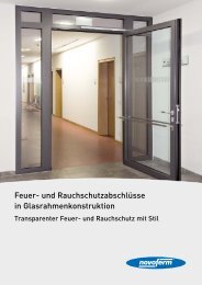
020806 D-GB-F-E-NL 09-09 Text - Novoferm
020806 D-GB-F-E-NL 09-09 Text - Novoferm
020806 D-GB-F-E-NL 09-09 Text - Novoferm

You also want an ePaper? Increase the reach of your titles
YUMPU automatically turns print PDFs into web optimized ePapers that Google loves.
<strong>GB</strong><br />
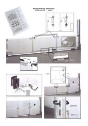
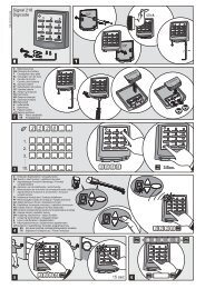
25a. Loosen bolts on motor head with wrenches<br />
(SW 10 and 17mm) 25b and screw them back on<br />
the other side 25c.<br />
26 Low-mounted control unit<br />
If the control unit cannot be positioned directly<br />
underneath the track 26a, the coiled cable can<br />
then be routed to the motor head using the<br />
supplied second cable clamp and the punched<br />
tape 26b. The extendible part of the coiled cable<br />
may be stretched by a maximum of factor 3 and the<br />
permanently laid part by a maximum of factor 7.<br />
If the coiled cable is not long enough, the<br />
extension set (accessory) should be used.<br />
27 Connection for wicket door contact<br />
The option of connecting the wicket door contact<br />
to drive unit is an advantage.<br />
- Remove housing 27a.<br />
- On the white plastic component, break out the<br />
side wall towards the door 27b.<br />
- Route cable from wicket door contact over the<br />
lifting arm and fasten with cable binder 27c.<br />
- Remove jumper from terminal block 27d and<br />
insert cable 27e.<br />
- Place housing back on again and screw down<br />
27f.<br />
Check: Open wicket door, "8" is displayed.<br />
• Operating Instructions<br />
• Information regarding the operating<br />
instructions<br />
These operating instructions describe how to use<br />
the product properly and safely. The safety advice<br />
and instructions as well as the local health and<br />
safety regulations and general safety regulations<br />
for the range of use must be observed.<br />
All persons using the door system must<br />
be shown how to operate it properly and<br />
safely.<br />
- When the operator is being actuated, any<br />
opening and closing phases must be<br />
monitored.<br />
- Keep hand transmitters out of the reach of<br />
children.<br />
- It must be ensured that neither persons nor<br />
objects are located within the door's range of<br />
travel.<br />
• Functional sequence<br />
The garage door operator can be actuated by<br />
push-button on the control unit (figure 23) or by<br />
other impulse generators, such as hand<br />
transmitters, key switches etc. It is only necessary<br />
to generate a short, sharp impulse.<br />
- Initial impulse:<br />
Operator starts up and causes the door to travel<br />
to the set OPEN or CLOSE end-of-travel<br />
positions.<br />
- Impulse generated whilst the door is in motion:<br />
Door stops<br />
- A new impulse:<br />
Door continues to move but in the opposite<br />
direction.<br />
• Internal safety device<br />
If the closing door encounters an obstruction, the<br />
operator stops and causes the door to open to its<br />
top end-of-travel position in order to clear the<br />
obstruction.<br />
During the last 2 seconds of closing, the door only<br />
opens slightly, this being sufficient to clear the<br />
obstruction but otherwise preventing anyone from<br />
being able to see inside the garage.<br />
If the opening door encounters an obstruction, the<br />
operator stops immediately. The door can be<br />
closed again by generating a new impulse.<br />
• External safety devices<br />
- Wicket door contact STOP A<br />
An open wicket door stops the operator<br />
immediately or prevents it from starting up.<br />
- Photocell defective (STOP B)<br />
If the photocell is interrupted whilst the door is<br />
closing, the door stops and reverses direction.<br />
An interruption whilst the door is opening has no<br />
effect.<br />
• Quick release<br />
When altering settings or making adjustments, in<br />
the event of a power failure or malfunctions, the<br />
door can be disengaged from the operator by<br />
actuating the pull cord with knob on the lifting arm<br />
(figure 24a), so that it can be operated manually.<br />
To resume operation of the operator, press the<br />
lever on the motor head (figure 24c) and the<br />
operator re-engages.<br />
If the door is to be operated manually over a longer<br />
period of time, then the door latches which were<br />
taken out of service for power operation, must be<br />
refitted, otherwise the door will not be latched<br />
when closed.<br />
• Lighting<br />
The lighting switches on automatically whenever a<br />
start impulse is generated and switches off again<br />
after the set time phase (factory setting approx. 90<br />
seconds).<br />
A second button on the hand transmitter can be<br />
programmed for 4-minutes light (figure 22). When<br />
the button on the hand transmitter is pressed, the<br />
light switches on independent of the motor and<br />
switches off again after approx. 4 minutes.<br />
• Changing the light bulb<br />
Pull out the mains plug and open the lamp shade<br />
using a Phillips screwdriver size 2 x 100. Replace<br />
the light shade (230 V, 40 W, cap E27) and screw<br />
the lamp cover back on again.<br />
• Signal light<br />
If a signal light for signalling the opening and<br />
closing phases is installed, this flashes together<br />
with the lamp in the operator as soon as a start<br />
impulse is generated. The operator starts with a<br />
time delay in accordance with the set early warning<br />
phase (see Special Settings in menu stage 7).<br />
• Hand transmitters<br />
- Programming further hand transmitters:<br />
See menu stages 1 and 2 (figures 21 and 22).<br />
- Changing the battery: slide back the battery<br />
compartment cover on the hand transmitter.<br />
Take out the battery.<br />
- Insert a new battery (alkaline 23A, 12V). Be sure<br />
to pole correctly! Slide the cover back on.<br />
Empty batteries must be disposed of<br />
separately (toxic waste)!<br />
• Further operating modes:<br />
In menu 9 another operating mode can be<br />
selected. The corresponding setting for menu 9<br />
appears in brackets.<br />
• Normal operation for ventilation position (1)<br />
The ventilation position is designed to allow<br />
ventilation of the garage. For this, the door is<br />
opened approx. 10 cm.<br />
Actuation as for normal operation.<br />
nd<br />
By pressing the 2 button on the hand transmitter<br />
or generating an impulse via another device, the<br />
door can be brought into the ventilation position<br />
from the open or closed state.<br />
From the ventilation position the door can be<br />
closed again via all impulse generators.<br />
• Operation on a side-opening sectional door<br />
(2)<br />
Instead of opening the door fully, the door can be<br />
partially opened by approx. 1 m in order to provide<br />
access to the garage.<br />
nd<br />
By pressing the 2 button on the hand transmitter<br />
or generating an impulse via another device, the<br />
door can be brought into the partially open state<br />
from any given position.<br />
• Maintenance / Checks<br />
For your own safety we recommend<br />
that the door system be checked by a<br />
specialist after initial installation and<br />
then regularly at intervals of 1 year<br />
minimum.<br />
• Monitoring the force limit<br />
The operator control unit features a dual-processor<br />
safety system to monitor the force limit.<br />
The integral force cut-out is automatically tested at<br />
each end-of-travel position.<br />
The door system must be checked before initial<br />
operation and at least once a year thereafter, In<br />
the process, the force limiting device (figure 20)<br />
must be tested!<br />
CAUTION! If the closing force is set too<br />
high, this can result in injury to persons and<br />
damage to property.<br />
The opening force can be re-adjusted in menu<br />
stage 5, the closing force in menu stage 6.<br />
Retain these installation, operating and maintenance instructions for the full duration of the operator’s service life!