020806 D-GB-F-E-NL 09-09 Text - Novoferm
020806 D-GB-F-E-NL 09-09 Text - Novoferm
020806 D-GB-F-E-NL 09-09 Text - Novoferm

You also want an ePaper? Increase the reach of your titles
YUMPU automatically turns print PDFs into web optimized ePapers that Google loves.
<strong>GB</strong><br />
• Installation Instructions<br />
INSTALLATION SHOULD O<strong>NL</strong>Y BE<br />
CARRIED OUT BY SUITABLY QUALIFIED<br />
PERSONS!<br />
Incorrect installation can put the safety of persons<br />
at risk or cause damage to property! Improper<br />
installation shall exempt the manufacturer from all<br />
liability.<br />
Preparing for installation<br />
1. To connect to the mains, a power point must be<br />
installed on site - the included mains lead is<br />
approx. 1 m long.<br />
2. Check the stability of the door, retighten the<br />
screws and nuts on the door.<br />
3. Check that the door is running smoothly and is<br />
in good working order, lubricate the shafts and<br />
bearings. Check the pretension of the springs<br />
and, if necessary, re-adjust.<br />
4. Dismantle the existing door latches (bolt plate<br />
and catches).<br />
5. For garages without a second entrance, an<br />
emergency release is required (accessory).<br />
6. If a wicket door is included, fit the wicket door<br />
contact.<br />
7. Check the supplied screws and wall plugs to<br />
ensure that these are suitable for the structural<br />
conditions on site.<br />
0 Required tools<br />
- Drilling machine with 6 mm masonry drill<br />
- Sturdy side cutter<br />
- Wrench, sizes 13, 15 and 17 mm<br />
- Slotted screwdriver, 3 mm wide<br />
- Phillips screwdriver, size 2 x 100 mm<br />
1 Choosing the installation side<br />
Choose the installation side in accordance with the<br />
structural conditions on site. The standard<br />
installation side is on the right (as viewed from the<br />
inside). For special installation situations<br />
see 25 .<br />
Spray the track with silicone to achieve optimum<br />
running qualities.<br />
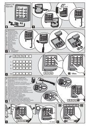
2 Fitting the toothed belt<br />
The top door track is used for installing the drive<br />
unit. Place the toothed belt with prefitted end clamp<br />
in the track (back of toothed belt facing upwards).<br />
2a Slot end clamp with hook onto vertical formed<br />
end piece.<br />
2b To disengage the drive wheel, actuate the lever.<br />
Feed the toothed belt through the drive wheels of<br />
the motor head as shown.<br />
2c Insert drive unit with the drive wheels into the<br />
top track.<br />
2d Inserting the limit stop.<br />
Position the limit stop at a distance ordering height<br />
+ 50 cm from the frame under the toothed belt.<br />
The limit stop should stop the operator approx. 5<br />
cm above the desired open position.<br />
Finally, push end of toothed belt through the<br />
opening in the end assembly angle.<br />
3 Fitting the rear toothed belt fastening<br />
3a Feed the toothed belt through the end assembly<br />
angle and keep it taut. Slot sleeve halves, as<br />
shown in 3b/3c, onto the toothed belt. Attach<br />
knurled nuts 3d and turn to tension the toothed belt<br />
by hand.<br />
3e Make sure that you do not twist the toothed<br />
belt in the process.<br />
3f If the toothed belt overhangs, it can be<br />
shortened.<br />
4 Inserting the top track roller<br />
4a + 4b Remove the track roller's extension ring<br />
4c Insert the track roller into the track, adjust and<br />
screw in place in accordance with the figure<br />
shown.<br />
5 Fastening the door bracket<br />
Place the door bracket on the designated drill<br />
holes of the top door leaf section and screw down<br />
with 3 self-tapping screws 6.3 x 16.<br />
6 Inserting the lifting arm<br />
6a Slot the lifting arm onto the bolt of the motor<br />
head and secure with clip.<br />
6b Hold the other side of the lifting arm between<br />
the door bracket and select hole setting (VL setting<br />
for construction years prior to 2006).<br />
6c Push the bolt all the way through and secure<br />
with clip. Connect door to operator.<br />
7 Sliding block<br />
Slot the sliding block onto the track profile, push<br />
into the rear opening on the motor head and screw<br />
down with screw 4.2 x 13.<br />
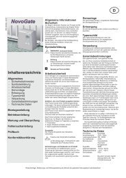
8 Mains lead cable<br />
The back of the control unit includes a chamber 8a,<br />
where, if required, the excess mains lead can be<br />
stowed 8b.<br />
9 Connecting the coiled cable<br />
9a At the back of the control unit there is a cable<br />
terminal for the two individual wires.<br />
9b Insert red wire on left (1) and green wire on<br />
right (2) into the terminal.<br />
9c Insert plug (3) into designated socket and allow<br />
to engage.<br />
9d Afterwards, feed the cable through labyrinth.<br />
10 Fastening the control unit<br />
10a Install the control unit onto the side wall. At a<br />
distance of approx. 1m from the door and 1.50m<br />
from the floor, mark the spot for the first plug hole,<br />
drill the hole, insert the plug but do not screw in<br />
fully. Place the control unit with key hole onto the<br />
screw head.<br />
10b Align the unit and mark the remaining fixing<br />
holes, drill holes, plug and fasten with screws<br />
4.2 x 32.<br />
11 Wall clamp<br />
Hold up the coiled cable in a vertical position. The<br />
maximum extension of the horizontally routed<br />
cable may not exceed three times the original<br />
length. Attach the wall clamp at the bend. Hold the<br />
clamp against the wall, mark the spot, drill, plug<br />
and screw to the wall using screw 4.2 x 45.<br />
12 Connecting plan / aligning the aerial<br />
Instructions: Do not connect any<br />
current-carrying cables, only connect volt-<br />
! free push buttons and volt-free relay<br />
outputs.<br />
Where door systems are used by the<br />
public or are impulse-operated out of sight<br />
of the door, a photocell must be installed.<br />
E. Connection for aerial<br />
Route the aerial on the housing exit upwards.<br />
When using an external aerial, the shielding<br />
must be assigned to the adjacent terminal (F, on<br />
right) 12b.<br />
F. Connection for external impulse generator 12b<br />
(accessories, e.g. key switch or digital coder)<br />
G. Input STOP A<br />
Connection for safety devices<br />
(accessories, e.g. wicket door contact).<br />
An interruption at this input end causes the door<br />
to stop during the opening or closing phase or<br />
prevents the operator from starting up in either<br />
direction. Connection for safety devices 12c<br />
(accessories).<br />
H. Input STOP B<br />
An interruption at this input end causes the<br />
operator to automatically change direction<br />
during the closing phase only.<br />
Connection for 2 wire light barrier EXTRA 626<br />
12d (accessories).<br />
Connection for an optical closing edge<br />
protection OSE 12e.<br />
I. Voltage supply 24 V ~<br />
(e.g. for one-way photocell), connection can<br />
take a max. load of 100 mA (do not exceed!).<br />
Connection for 24V signal lamp12f<br />
(accessories). Connection for an external<br />
receiver 12g (accessories).<br />
J. Plug-in base for radio receiver<br />
K. Connection for an external light, protected light<br />
or signal lamp (protection classification II, max.<br />
500W) 12h (accessories).<br />
13 Lamp shade<br />
13a The lamp shade conceals the terminal<br />
connections. To do this, feed the back part of the<br />
lamp shade underneath the guides of the control<br />
unit.<br />
13b Fasten the lamp shade with two self-tapping<br />
screws 4.2 x 16.<br />
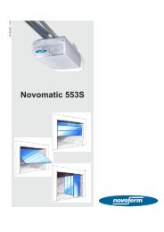
14 Control elements<br />
14a/b The control elements for programming the<br />
door operator are located behind the white cover.<br />
The cover can be opened with a screwdriver.<br />
Once the operator has been programmed, the<br />
cover is reclosed and serves as an interior pushbutton<br />
23.<br />
A. The numerical display serves to indicate the<br />
menu stage, the respectively set value and the<br />
error/fault diagnosis.<br />
a. The incremental display, lights up to indicate<br />
readiness for operation and flashes on<br />
acknowledgement of learned hand transmitter<br />
codes.<br />
B. During the setting / adjustment phase button<br />
serves as an "UP" button and outside the menu<br />
as a START button.<br />
C. During the setting / adjustment phase button<br />
serves as a "DOWN" button.<br />
D. Button serves to call up the settings /<br />
adjustment menu, to change the menu stages<br />
and store the settings.<br />
Programming the control unit is menu-driven.<br />
Pressing button , calls up menu prompting. The<br />
numbers displayed indicate the menu stage. After<br />
approx. 2 seconds, the display flashes and the<br />
setting can be altered via buttons and . The<br />
selected setting is stored via button and the<br />
programme automatically jumps to the next menu<br />
stage. By repeatedly pressing the button ,<br />
menu stages can be skipped. To quit the menu,<br />
repeatedly press button until "0" is displayed<br />
again. Outside the menu, button can be used to<br />
generate a start impulse.<br />
15 Menu stage 3: setting the top end-of-travel<br />
position<br />
15a Keep button pressed for 3 seconds. A "3"<br />
is displayed.<br />
Wait a short while until the "3" flashes.<br />
15b Press button and check to see that the door<br />
Retain these installation, operating and maintenance instructions for the full duration of the operator’s service life!