www.cardin.it
www.cardin.it
www.cardin.it

Create successful ePaper yourself
Turn your PDF publications into a flip-book with our unique Google optimized e-Paper software.
SERIAL Nr.<br />
ZVL407.06<br />
CARDIN ELETTRONICA S.p.A<br />
Via del lavoro, 73 – 31013 Codognè – Zona Industriale Cimavilla (TV) Italy<br />
Tel: +39/0438.404011 / Fax: +39/0438.401831<br />
<strong>www</strong>.<strong>cardin</strong>.<strong>it</strong><br />
e-mail (Italy): sales.office.<strong>it</strong>@<strong>cardin</strong>.<strong>it</strong><br />
e-mail (Europe): sales.office@<strong>cardin</strong>.<strong>it</strong><br />
NAME<br />
MODEL<br />
The S449 series conforms to the essential requirements of the directive 99/05/CE and the<br />
technical reference standards have been applied.<br />
Frequency valid<strong>it</strong>y: 433.92 MHz for all<br />
DATE<br />
S449 FM 14.01.2013<br />
countries<br />
RADIOCOMANDO DIGITALE A CODICI ROLLING<br />
Messa in funzione ed uso pagine 2-9<br />
Disegni tecnici d'installazione e riferimento pagine 42-51<br />
DIGITAL RADIOCONTROL WITH ROLLING CODES<br />
Set up and user instructions pages 10-17<br />
Installation and reference drawings pages 42-51<br />
RADIOCOMMANDE DIGITALE À ROLLING CODE<br />
Mise en service et utilisation pages 18-25<br />
Dessins techniques d’installation et référence pages 42-51<br />
DIGITALE FUNKSTEUERUNG MIT ROLLING CODES<br />
Inbetriebnahme und Benutzung Se<strong>it</strong>en 26-33<br />
Technische Installations- und Referenzzeichnungen Se<strong>it</strong>en 42-51<br />
RADIOMANDO DIGITAL DE CÓDIGOS ROLLING<br />
Puesta en función y uso del sistema páginas 34-41<br />
Dibujos técnicos de instalación y referencias páginas 42-51<br />
1
Avvertenze<br />
Il presente manuale si rivolge a persone abil<strong>it</strong>ate all'installazione di "Apparecchi utilizzatori di energia<br />
elettrica" e richiede una buona conoscenza della tecnica, eserc<strong>it</strong>ata in forma professionale. L'uso ed<br />
installazione di questa apparecchiatura deve rispettare rigorosamente le indicazioni forn<strong>it</strong>e dal costruttore e<br />
le normative di sicurezza vigenti.<br />
Attenzione! Solo per clienti dell’EU - Marcatura WEEE.<br />
Il simbolo indica che il prodotto alla fine della propria v<strong>it</strong>a utile deve essere raccolto separatamente<br />
dagli altri rifiuti. L’utente dovrà pertanto conferire l’apparecchiatura agli idonei centri<br />
di raccolta differenziata dei rifiuti elettronici ed elettrici, oppure riconsegnarla al rivend<strong>it</strong>ore al<br />
momento dell’acquisto di una nuova apparecchiatura di tipo equivalente, in ragione di uno<br />
a uno. L’adeguata raccolta differenziata per l’avvio al riciclaggio, al trattamento e allo smaltimento<br />
ambientalmente compatibile contribuisce ad ev<strong>it</strong>are possibili effetti negativi sull’ambiente e sulla<br />
salute e favorisce il riciclo dei materiali. Lo smaltimento abusivo del prodotto da parte del detentore<br />
comporta l’applicazione delle sanzioni amministrative previste dalla normativa vigente nello Stato<br />
Comun<strong>it</strong>ario di appartenenza.<br />
Descrizione<br />
Il sistema di radiocomando S449 in "FM" è composto da uno o più trasmett<strong>it</strong>ori e da uno o più ricev<strong>it</strong>ori che<br />
saranno combinati in relazione alle esigenze specifiche d'impianto. Nel ricev<strong>it</strong>ore si possono memorizzare<br />
fino a 300 codici diversi; i codici vengono, in fase di memorizzazione, trasfer<strong>it</strong>i in una memoria non volatile.<br />
Importante: Poiché ad ogni comando il codice trasmesso cambia, se la trasmissione viene interrotta da un<br />
disturbo, il ricev<strong>it</strong>ore si aspetta un codice diverso, pertanto per ristabilire il comando è necessario rilasciare<br />
e ripremere il tasto del trasmett<strong>it</strong>ore.<br />
2
Possibil<strong>it</strong>à d'impiego<br />
Il radiocomando S449 permette l'attuazione a distanza di apparecchiature elettriche ed elettroniche, trova<br />
il suo migliore impiego nel comando di sistemi di aperture automatiche, sistemi d'allarme ed in tutti gli<br />
impianti dove sia richiesta l'attuazione a distanza (senza fili) protetta da un codice segreto ad alta affidabil<strong>it</strong>à.<br />
Versioni trasmett<strong>it</strong>ori<br />
TXQ449100 Trasmett<strong>it</strong>ori tascabili 1 tasto<br />
TXQ449200 Trasmett<strong>it</strong>ori tascabili 2 tasti<br />
TXQ449300 Trasmett<strong>it</strong>ori tascabili 3 tasti<br />
TXQ449400 Trasmett<strong>it</strong>ori tascabili 4 tasti<br />
TXQ44940M Pulsantiera radio per fissaggio a muro 4 tasti<br />
TXQPRO449-4 Trasmett<strong>it</strong>ori industriali 4 tasti<br />
TXQPRO449-4A Trasmett<strong>it</strong>ori industriali con antenna esterna 4 tasti<br />
Versioni ricev<strong>it</strong>ori<br />
RQM449200 Ricev<strong>it</strong>ore mini 2 canali<br />
RSQ449200 Ricev<strong>it</strong>ore a scheda 2 canali<br />
RCQ449100 Ricev<strong>it</strong>ore modulare in cassetta 4 canali<br />
Attenzione: i trasmett<strong>it</strong>ori della serie TRQ449 prodotti fino al 2012 non hanno<br />
la funzione blocco tasto e sono forn<strong>it</strong>i con 2 batterie al l<strong>it</strong>io (2 x CR2032 6V)<br />
per ulteriore informazione scaricare l'istruzioni ZVL407.04 dal s<strong>it</strong>o <strong>www</strong>.<strong>cardin</strong>.<strong>it</strong><br />
3
Modulo di memoria (M1)<br />
Cost<strong>it</strong>u<strong>it</strong>a da una memoria non volatile di tipo EEPROM, contiene i codici dei trasmett<strong>it</strong>ori e permette la<br />
memorizzazione di 300 codici (300 tasti di canale). Nel modulo i codici vengono mantenuti anche in assenza<br />
di alimentazione.<br />
Installazione ricev<strong>it</strong>ore-antenna<br />
Per portata si intende la distanza utile di funzionamento fra trasmett<strong>it</strong>ore e ricev<strong>it</strong>ore con antenna installata,<br />
e misurata in spazio libero. La portata è quindi strettamente legata alle caratteristiche tecniche del sistema<br />
(potenza e sensibil<strong>it</strong>à) e varia in base alle caratteristiche del luogo di postazione. Per ottenere il funzionamento<br />
ottimale del radiocomando è bene scegliere con attenzione i punti d'installazione del ricev<strong>it</strong>ore e dell'antenna.<br />
È buona norma posizionare il ricev<strong>it</strong>ore a deb<strong>it</strong>a distanza da reti di sistemi computerizzati, da impianti d'allarme<br />
e da altre fonti di possibile disturbo.<br />
(Sistemazioni anomale potrebbero comprometterne in parte il funzionamento)<br />
Antenna<br />
L'installazione dell'antenna è fondamentale; collegata al ricev<strong>it</strong>ore rappresenta il punto di ricezione del<br />
radiocomando. È necessario collegare al ricev<strong>it</strong>ore un'antenna accordata mediante cavetto coassiale RG58<br />
(impedenza 50Ω) di lunghezza max. 15 m; l'antenna va posizionata all'esterno nel punto più elevato e visibile,<br />
lontano da strutture metalliche.<br />
Trasmett<strong>it</strong>ore<br />
Il trasmett<strong>it</strong>ore è precodificato e utilizza un circu<strong>it</strong>o integrato programmato in fabbrica con un numero<br />
identificativo unico per ogni trasmett<strong>it</strong>ore; tutti i parametri necessari alla codifica sono contenuti in questo<br />
circu<strong>it</strong>o integrato (non si utilizza una memoria esterna): questo rende molto più affidabile il meccanismo di<br />
gestione della codifica, e più sicuro il sistema. Il trasmett<strong>it</strong>ore possiede un meccanismo di auto-spegnimento<br />
dopo almeno 20 secondi di attivazione continuata (per lim<strong>it</strong>are il consumo della batteria).<br />
4
Funzione di blocco tasti<br />
• Il trasmett<strong>it</strong>ore ha la possibil<strong>it</strong>à di inserire la funzione di blocco tasti, modal<strong>it</strong>à che protegge l’apparecchio<br />
da attivazioni casuali (involontarie):<br />
- per attivare la funzione tenere premuto “MR” per 8 secondi finchè lampeggia<br />
il led rosso; a questo punto per attuare un comando sarà necessario premere<br />
tre volte consecutive il tasto voluto;<br />
- per ripristinare la funzione standard tenere premuto “MR” per 8 secondi<br />
finchè il led rosso lampeggia.<br />
Ricev<strong>it</strong>ori<br />
Attenzione! Alimentare il ricev<strong>it</strong>ore esclusivamente con un alimentatore di sicurezza. L'utilizzo di alimentatori<br />
non di sicurezza può provocare pericolo.<br />
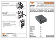
Ricev<strong>it</strong>ori in cassetta IP55 (fig. 6)<br />
- Il ricev<strong>it</strong>ore in cassetta è dotato di morsettiera a 14 vie (CS1120A) con collegamento elettrico:<br />
- 12V ac/dc tra i morsetti 1-2 - 24V ac/dc tra i morsetti 1-3<br />
Il fissaggio del ricev<strong>it</strong>ore in cassetta viene esegu<strong>it</strong>o servendosi Drawing della number staffa : DM0531 "fissaggio Description rapido". : La staffa viene<br />
fissata alla parete con due tasselli (curare la messa in bolla). Product Esegu<strong>it</strong>i Code : RCQ449100 i collegamenti elettrici, il conten<strong>it</strong>ore<br />
Draft : P.J.Heath Date : 13-04-2001<br />
viene inser<strong>it</strong>o a scatto sulla stessa staffa. In caso di manutenzione è sufficiente una pressione operata sulla<br />
scatola, dal basso verso l'alto per ottenere lo sganciamento del conten<strong>it</strong>ore.<br />
Moduli di canale intercambiabili<br />
Nel ricev<strong>it</strong>ore in cassetta le funzioni sono indicate in serigrafia sul circu<strong>it</strong>o stampato; i moduli di canale<br />
intercambiabili devono assumere unicamente la seguente configurazione:<br />
- da 1 a 4 strips impulsive MCC4491R0<br />
Ricev<strong>it</strong>ori a scheda (fig. 7)<br />
Attenzione! La scheda va adeguatamente isolata dalle parti delle apparecchiature in cui viene incorporata<br />
e che si trovano a tensione di rete.<br />
- il ricev<strong>it</strong>ore (CS1134) viene inser<strong>it</strong>o direttamente nell'apparecchiatura predisposta a riceverlo con collegamento<br />
elettrico 24V ac/dc tra i pin 3-4.<br />
5<br />
MR<br />
MEMORIZZAZIONE CODICE TX-RX<br />
CARDIN ELETTRONICA S.p.A - 31020 San Vendemiano (TV) Italy - via Raffaello, 36 Tel: 0438/401818 Fax: 043
Il ricev<strong>it</strong>ore a scheda ha due relé le cui usc<strong>it</strong>e sono contrassegnate rispettivamente con CH1 (solo contatto N.A.)<br />
e CH2 (contatto N.A. - N.C.). I relé CH1 e CH2 possono essere attivati selezionando, con dei jumper "J1" s<strong>it</strong>uati<br />
sul circu<strong>it</strong>o, le funzioni A,B,C,D corrispondenti alle funzioni CHA,CHB,CHC,CHD del trasmett<strong>it</strong>ore (vedi fig. 7).<br />
Ricev<strong>it</strong>ori mini IP20 (fig. 8)<br />
- Il ricev<strong>it</strong>ore (CS1134) è dotato di conten<strong>it</strong>ore da interno e di morsettiera a 10 vie con collegamento elettrico:<br />
- 12V ac/dc tra i morsetti 7-8 - 24V ac/dc tra i morsetti 6-8.<br />
Il ricev<strong>it</strong>ore ha due relé le cui usc<strong>it</strong>e sono contrassegnate rispettivamente con CH1 (solo contatto N.A.) e CH2<br />
(contatto N.A. - N.C.). I relé CH1 e CH2 possono essere attivati selezionando, con dei jumper "J1" s<strong>it</strong>uati sul<br />
circu<strong>it</strong>o, le funzioni A,B,C,D corrispondenti alle funzioni CHA,CHB,CHC,CHD del trasmett<strong>it</strong>ore (vedi fig.8).<br />
Segnalazioni LED "L1" sul ricev<strong>it</strong>ore:<br />
lampeggio veloce: cancellazione singolo utente<br />
lampeggio lento: memorizzazione di un utente<br />
sempre acceso: memoria interamente occupata.<br />
Funzioni<br />
Attenzione! Prima di procedere alla prima memorizzazione dei trasmett<strong>it</strong>ori, ricordarsi di cancellare<br />
interamente la memoria.<br />
Memorizzazione di un canale (fig. 5a, 6, 7 ,8)<br />
1) Premere il pulsante "P1" MEMO sul ricev<strong>it</strong>ore e tenerlo premuto: il LED "L1" lampeggia lentamente<br />
2) Attivare il trasmett<strong>it</strong>ore sul canale da memorizzare<br />
3) Tenere sempre premuto "P1" ed attendere finchè il LED "L1" riprende a lampeggiare<br />
4) Attivare una seconda volta il trasmett<strong>it</strong>ore (stesso trasmett<strong>it</strong>ore, stesso canale; se il canale è diverso oppure<br />
si tratta di un altro trasmett<strong>it</strong>ore la memorizzazione termina senza successo);<br />
5) Fine della memorizzazione: il LED "L1" rimane acceso per 2 secondi, segnalando la corretta memorizzazione.<br />
Rilasciare il pulsante "P1".<br />
6
• Non è possibile memorizzare un utente che sia già in memoria: in un caso simile durante l’attivazione del<br />
radiocomando (punto 2) si interrompe il lampeggio del LED. Solo dopo il rilascio del pulsante "P1" MEMO<br />
il programma riprenderà a funzionare.<br />
• Se dopo la prima attivazione del radiocomando non lo si attiva per la seconda volta, dopo 15 secondi si<br />
esce automaticamente dalla modal<strong>it</strong>à di memorizzazione senza memorizzare il nuovo codice utente.<br />
• Se la prima volta si attiva un canale che non è già memorizzato, ma la seconda volta si attiva un altro canale<br />
già memorizzato si esce dalla procedura di memorizzazione (perché i due codici non corrispondono) e si<br />
ha l’attivazione del canale scelto nella seconda trasmissione.<br />
Quando la memoria del ricev<strong>it</strong>ore è prossima al completamento, la ricerca dell’utente può durare un massimo<br />
di 1 secondo da quando è stato ricevuto il comando.<br />
Cancellazione di un canale (fig. 5a, 6, 7, 8)<br />
1) Premere il pulsante "P2" DELETE sul ricev<strong>it</strong>ore e tenerlo premuto: il LED "L1" lampeggia velocemente<br />
2) Attivare il trasmett<strong>it</strong>ore sul canale da cancellare<br />
3) Il LED rimane acceso per 2 secondi, segnalando l’avvenuta cancellazione<br />
Nota: se l’utente che si vuole cancellare non è in memoria, il LED smette di lampeggiare; il programma<br />
riprenderà il normale svolgimento solo dopo il rilascio del pulsante "P2".<br />
Sia per la procedura di memorizzazione che per quella di cancellazione, se si rilascia il tasto prima dell’attivazione<br />
del radiocomando si esce sub<strong>it</strong>o dalla modal<strong>it</strong>à.<br />
Cancellazione completa della memoria utenti (fig. 6, 7, 8):<br />
1) Tenere premuti entrambi i pulsanti ("P1+P2") sul ricev<strong>it</strong>ore per più di 4 secondi<br />
2) Il LED "L1" rimane acceso per tutto il tempo della cancellazione (8 secondi circa).<br />
3) Il LED "L1" si spegne: la cancellazione è stata completata.<br />
Memorizzazione di ulteriori canali via radio (fig. 5)<br />
• La memorizzazione può essere attivata via radio (senza aprire la scatola dove è alloggiato il ricev<strong>it</strong>ore) se<br />
il jumper "J3" è inser<strong>it</strong>o (fig. 6, 7, 8).<br />
1) Assicurarsi che il jumper "J3" sia inser<strong>it</strong>o sul ricev<strong>it</strong>ore<br />
7
2) Utilizzando un radiocomando, in cui almeno uno dei tasti di canale "A-B-C-D" sia già stato memorizzato<br />
nel ricev<strong>it</strong>ore, attivare il tasto "MR" come indicato in figura "5".<br />
Nota: Tutti i ricev<strong>it</strong>ori raggiungibili dall'emissione del radiocomando, e che abbiano almeno un canale del<br />
trasmett<strong>it</strong>ore memorizzato, attiveranno contemporaneamente il buzzer di segnalazione "B1" (fig. 6,7,8).<br />
3) Attivare uno dei tasti di canale del trasmett<strong>it</strong>ore. I ricev<strong>it</strong>ori che non contengono il codice di tale tasto si<br />
disattiveranno, con l'emissione di un "bip" lungo 5 secondi; quello invece che contiene il codice emetterà<br />
un altro "bip" che dura un secondo, entrando effettivamente nella modal<strong>it</strong>à di memorizzazione "via radio".<br />
4) Premere un tasto di canale sul trasmett<strong>it</strong>ore da memorizzare; ad avvenuta memorizzazione il ricev<strong>it</strong>ore<br />
emetterà 2 "bip" di mezzo secondo, dopodiché il ricev<strong>it</strong>ore sarà pronto a memorizzare un altro codice.<br />
5) Per uscire dalla modal<strong>it</strong>à lasciare trascorrere 3 secondi senza memorizzare codici. Il ricev<strong>it</strong>ore emetterà<br />
un "bip" lungo 5 secondi ed uscirà dalla modal<strong>it</strong>à.<br />
• Quando la memoria viene completamente occupata, il buzzer emetterà 10 "bip" ravvicinati, uscendo<br />
automaticamente dalla modal<strong>it</strong>à di memorizzazione "via radio", ed il LED "L1" rimane acceso; la stessa<br />
segnalazione si ottiene anche ad ogni tentativo di entrare in modal<strong>it</strong>à "via radio" con memoria interamente<br />
occupata.<br />
8
CARATTERISTICHE TECNICHE<br />
RICEVITORE<br />
- frequenza di ricezione...................................................................................................................433,92 MHz<br />
- sensibil<strong>it</strong>à (per segnale a buon fine)........................................................................................-110dBm 0,7µV<br />
- modulazione...............................................................................................................................................FSK<br />
- impedenza di ingresso antenna................................................................................................................ 50 Ω<br />
- alimentazione ricev<strong>it</strong>ore ..............................................................................................................12/24V ac/dc<br />
- assorbimento a riposo/con 1 relé attivato........................................................................................20/40 mA<br />
- massima potenza commutabile dal relé con carico resistivo:<br />
carico in ac/dc ............................................................................................................................... 60VA/24 W<br />
tensione massima ........................................................................................................................... 30V ac/dc<br />
- r<strong>it</strong>ardo all'attivazione del relè........................................................................................................ 80 ÷ 100 ms<br />
- temperatura di esercizio..............................................................................................................-20°…+75 °C<br />
TRASMETTITORE<br />
- frequenza di trasmissione............................................................................................................ 433,92 MHz<br />
- potenza apparente irradiata..................................................................................-10…-7dBm (100-200 µW)<br />
- modulazione........................................................................................................................................ FM/FSK<br />
- alimentazione (batteria l<strong>it</strong>io) ................................................................................................... 3V (1 x CR2032)<br />
- assorbimento.......................................................................................................................................... 18 mA<br />
- temperatura di esercizio..............................................................................................................-10°…+55 °C<br />
- umid<strong>it</strong>à relativa.........................................................................................................................................
REMARKS<br />
These instructions are aimed at professionally qualified "installers of electrical equipment" and must respect<br />
the local standards and regulations in force. The use and installation of these appliances must rigorously<br />
respect the indications supplied by the manufacturer and the safety standards and regulations in force.<br />
Attention! Only for EU customers - WEEE marking. This symbol indicates that once the<br />
products life-span has expired <strong>it</strong> must be disposed of separately from other rubbish. The<br />
user is therefore obliged to e<strong>it</strong>her take the product to a su<strong>it</strong>able differential collection s<strong>it</strong>e for<br />
electronic and electrical goods or to send <strong>it</strong> back to the manufacturer if the intention is to<br />
replace <strong>it</strong> w<strong>it</strong>h a new equivalent version of the same product. Su<strong>it</strong>able differential collection,<br />
environmental friendly treatment and disposal contributes to avoiding negative effects on the ambient<br />
and consequently health as well as favouring the recycling of materials. Illic<strong>it</strong>ly disposing of this<br />
product by the owner is punishable by law and will be dealt w<strong>it</strong>h according to the laws and standards<br />
of the individual member nation.<br />
Description<br />
The S449 Radio control system in "FM" consists of one or more transm<strong>it</strong>ters and one or more receivers<br />
which can be combined to meet the specific needs of the system. The generated code is memorised in the<br />
receiver via radio. The receiver is able to memorise up to 300 different codes.<br />
Important: The transm<strong>it</strong>ted code changes for each command (rolling code). If disturbance interrupts the<br />
transmission, the receiver will wa<strong>it</strong> for a different code, the relay can then only be activated by first releasing<br />
and then pressing the transm<strong>it</strong>ter channel button again.<br />
10
Use<br />
The S449 radio control allows the remote activation of electrical and electronic appliances w<strong>it</strong>h <strong>it</strong>s best use<br />
in the following areas: automatic opening systems, alarm systems, and in all systems which require remote<br />
control activation (w<strong>it</strong>hout wires) using secret codes.<br />
Transm<strong>it</strong>ter versions<br />
TXQ449100 Miniaturised transm<strong>it</strong>ters 1 Button<br />
TXQ449200 Miniaturised transm<strong>it</strong>ters 2 Buttons<br />
TXQ449300 Miniaturised transm<strong>it</strong>ters 3 Buttons<br />
TXQ449400 Miniaturised transm<strong>it</strong>ters 4 Buttons<br />
TXQ44940M Wall mounted transm<strong>it</strong>ter 4 Buttons<br />
TXQPRO449-4 Industrial transm<strong>it</strong>ters 4 Buttons<br />
TXQPRO449-4A Industrial transm<strong>it</strong>ters + aerial 4 Buttons<br />
Receiver versions<br />
RQM449200 Mini receiver 2 Channels<br />
RSQ449200 Slot-in receiver card 2 Channels<br />
RCQ449100 Outdoor receiver 4 Channels<br />
Attention: the transm<strong>it</strong>ters of the series TRQ449 produced before 2012 do<br />
not have the key block function and are supplied w<strong>it</strong>h 2 l<strong>it</strong>hium batteries (2 x<br />
CR2032 6V) for more information download the instructions ZVL407.04 from<br />
<strong>www</strong>.<strong>cardin</strong>.<strong>it</strong><br />
11
Memory module (M1)<br />
The module is furnished w<strong>it</strong>h a non volatile EEPROM type memory and contains the transm<strong>it</strong>ter codes and<br />
allows you to memorise up to 300 codes (300 channel buttons). The programmed codes are maintained in<br />
this module even in the absence of power.<br />
Receiver antenna installation<br />
‘Range’ is intended to mean the working distance, measured in free space, between the receiver and the<br />
transm<strong>it</strong>ter w<strong>it</strong>h the antenna installed. The range is therefore closely linked to the technical characteristics of<br />
the system (power and sensibil<strong>it</strong>y) and varies according to the characteristics of the s<strong>it</strong>e in which the system<br />
is located. It therefore follows that to obtain the best results from the radio control the receiver and antenna<br />
installation s<strong>it</strong>es should be carefully chosen. It is good practise to pos<strong>it</strong>ion the receiver away from computer<br />
systems, alarm systems and other possible sources of disturbance.<br />
A bad choice of pos<strong>it</strong>ioning could compromise the performance of the receiver.<br />
Antenna<br />
The installation of the antenna is fundamental, connected to the receiver <strong>it</strong> represents the reception point<br />
for the radio control. When installing the antenna the following points should be observed. A tuned antenna<br />
using a coaxial cable RG58 (impedance 50Ω) w<strong>it</strong>h a maximum length of 15 m. must be installed. The antenna<br />
should be pos<strong>it</strong>ioned out of doors in the highest possible point, visible and away from metal structures.<br />
Transm<strong>it</strong>ters<br />
The transm<strong>it</strong>ter is pre-coded and is f<strong>it</strong>ted w<strong>it</strong>h an integrated circu<strong>it</strong> which is programmed in the factory<br />
w<strong>it</strong>h a unique identification number. All the code parameters are contained in this integrated circu<strong>it</strong> (external<br />
memory modules are not required) thus making code management more reliable and the system more<br />
secure. The transm<strong>it</strong>ter has an automatic shut down mechanism which cuts in after at least 20 seconds of<br />
continuous use (this lim<strong>it</strong>s battery consumption).<br />
12
Key block function<br />
• A key block function has been added to protect the appliance from accidental activation;<br />
- to activate the function press and hold down “MR” for 8 seconds until the<br />
red led starts flashing, at this point to activate a command you will need<br />
to press the required key three times consecutively;<br />
- to reset the function to standard operation standard press and hold down<br />
“MR” for 8 seconds until the red led starts flashing.<br />
Receivers<br />
Warning! The receivers must only be powered by a safety power pack. The use of non safety power<br />
packs could provoke damage to the system.<br />
Outdoor receivers IP55 (fig. 6)<br />
- The outdoor receiver card (CS1120A) is f<strong>it</strong>ted w<strong>it</strong>h an 14-way terminal board and has the following electrical connections:<br />
- 12V ac/dc between binding posts 1-2 - 24V ac/dc between binding posts 1-3.<br />
The outdoor receiver is f<strong>it</strong>ted using "fast-f<strong>it</strong>ting" brackets. The Drawing bracket number : DM0531 should be fixed Description to the : wall using two<br />
rawlplugs (check that <strong>it</strong> is in square). After connecting the<br />
Product<br />
wiring<br />
Code<br />
the<br />
: RCQ449100<br />
case should be slid onto the bracket<br />
Draft : P.J.Heath Date : 13-04-2001<br />
therefore fixing <strong>it</strong> to the wall. If any repair work is necessary the case can be easily extracted by pushing<br />
upwards the action of which will separate <strong>it</strong> from the bracket.<br />
Interchangeable channel modules<br />
In the receivers the channel functions are printed on the circu<strong>it</strong> board. The interchangeable channel modules<br />
can only have the following configuration:<br />
- from 1 to 4 impulsive relay strips MCC4491R0<br />
Slot-in receiver cards (fig. 7)<br />
Warning! The receiver cards must be sufficiently insulated from the parts of the host device which are powered by the mains.<br />
- The receiver card (printed circu<strong>it</strong> CS1134) is inserted directly into an appliance which is designed to receive<br />
<strong>it</strong> and has the following electrical connections: 24V ac/dc between binding posts 3-4.<br />
13<br />
MR<br />
MEMORIZZAZIONE CODICE TX-RX<br />
CARDIN ELETTRONICA S.p.A - 31020 San Vendemiano (TV) Italy - via Raffaello, 36 Tel: 0438/401818 Fax: 0438/4
The receiver cards are f<strong>it</strong>ted w<strong>it</strong>h two relays the outputs of which are marked CH1 (N.O. contact) and CH2<br />
(N.O./N.C. contact). The relays CH1 and CH2 can be activated by selecting the functions A-B-C-D and made<br />
to correspond w<strong>it</strong>h the transm<strong>it</strong>ter channels CHA-CHB-CHC-CHD by setting the jumpers "J1" s<strong>it</strong>uated on<br />
the circu<strong>it</strong> board (see fig. 7).<br />
Mini receivers IP20 (fig. 8)<br />
- The mini receiver (printed circu<strong>it</strong> CS1134) is housed in an indoor container and is f<strong>it</strong>ted w<strong>it</strong>h an 8-way<br />
terminal board w<strong>it</strong>h the following electrical connections:<br />
- 12V ac/dc between binding posts 7-8 - 24V ac/dc between binding posts 6-8.<br />
The receiver cards are f<strong>it</strong>ted w<strong>it</strong>h two relays the outputs of which are marked CH1 (N.O. contact) and CH2<br />
(N.O./N.C. contact). The relays CH1 and CH2 can be activated by selecting the functions A-B-C-D and made<br />
to correspond w<strong>it</strong>h the transm<strong>it</strong>ter channels CHA-CHB-CHC-CHD by setting the jumpers "J1" s<strong>it</strong>uated on<br />
the circu<strong>it</strong> board (see fig.8).<br />
Status led "L1" on the receiver<br />
Flashing rapidly: cancelling a single user<br />
Flashing slowly memorising a single user<br />
Continuously l<strong>it</strong>: memory full<br />
Functions<br />
Attention! Before memorising the transm<strong>it</strong>ters for the first time remember to cancel the entire<br />
memory content.<br />
Memorising a channel (fig. 5a,6,7,8)<br />
1. Keep button "P1" MEMO pressed down and the led "L1" will start to flash slowly<br />
2. Press the channel on the transm<strong>it</strong>ter which is to be memorised.<br />
3. Keep button "P1" pressed down and wa<strong>it</strong> until LED "L1" starts to flash again.<br />
4. Press the channel on the transm<strong>it</strong>ter which is to be memorised again (same transm<strong>it</strong>ter, same channel.<br />
14
If the channel or the transm<strong>it</strong>ter is different you will not be able to memorise the channel.<br />
5. End of the memory procedure. LED "L1" will remain l<strong>it</strong> for 2 seconds meaning that the channel has<br />
been correctly memorised. Releae button "P1"<br />
• It is not possible to memorise a user code that is already in memory: In this case when the transm<strong>it</strong>ter<br />
is activated (point 2) the led will stop flashing. The program will only work again when button "P1"<br />
MEMO has been released.<br />
• If the transm<strong>it</strong>ter is not activated a second time w<strong>it</strong>hin fifteen seconds the program will automatically<br />
leave the memory mode w<strong>it</strong>hout memorising a new user code.<br />
• If a new user code is activated the first time and a different channel (w<strong>it</strong>h an already memorised user<br />
code) is activated the second time, the program will automatically leave the memory mode (because<br />
the two codes do not correspond) and the channel present in the second transmission will be activated.<br />
When the receiver's memory is almost full the user search function can take up to 1 second to complete.<br />
Cancelling a channel (fig. 5a, 6, 7, 8 )<br />
1. Keep button "P2" DELETE pressed down and the led "L1" will start to flash rapidly<br />
2. Press the channel on the transm<strong>it</strong>ter which is to be cancelled<br />
3. Led "L1" will remain l<strong>it</strong> for 2 seconds meaning that the channel has been cancelled.<br />
Note: If the user which is to be cancelled is not found in the memory, the led will stop flashing. The program<br />
will only work again when button "P2" has been released. If the button is released before a channel is<br />
activated the program will automatically leave the memorising or cancelling mode.<br />
Cancelling the entire user memory (fig. 6, 7, 8)<br />
1. Keep buttons (P1+P2) pressed down simultaneously for more than 4 seconds<br />
2. Led "L1" will remain l<strong>it</strong> for the period of time required for the program to cancel all the codes (about 8<br />
seconds)<br />
3. Led "L1" will turn off meaning that the cancellation procedure has been carried out.<br />
Memorising a channel (fig. 5)<br />
• Memorisation can be activated by radio (w<strong>it</strong>hout opening the receiver container) if jumper "J3" has<br />
15
een inserted (fig. 6, 7, 8).<br />
1. Make sure that the jumper "J3" has been inserted in receiver.<br />
2. Using a transm<strong>it</strong>ter, in which at least one channel button "A,B,C or D" has already been memorised<br />
in the receiver, press the button "MR" as shown in figure "5".<br />
Note: all the receivers w<strong>it</strong>hin range when the channel button is pressed (and which have at least one<br />
of the transm<strong>it</strong>ter channel buttons memorised) will activate their signal buzzer "B1" (fig. 6, 7, 8).<br />
3. Press one of the channel buttons on the transm<strong>it</strong>ter. The receivers which do not contain that channel<br />
code will sound a five-second long "beep" and will then disactivate. The receivers which contain the<br />
channel code will sound a one-second long "beep" and will enter the programming mode.<br />
4. Press one of the channel buttons on the transm<strong>it</strong>ter which you wish to memorise; the receiver will<br />
sound 2 "beeps" of half a second each after which the receiver will be ready to receive another code.<br />
5. To leave the programming mode wa<strong>it</strong> for 5 seconds w<strong>it</strong>hout pressing any buttons. The receiver will<br />
sound a five-second long "beep" and will then ex<strong>it</strong> the programming mode.<br />
• When the memory is entirely occupied the buzzer will sound 10 rapid "beeps" and will automatically<br />
leave the "programming via radio" mode.<br />
Led "L1" will remain l<strong>it</strong> on the receiver. The same signal is given each time you try to enter "programming<br />
via radio" when the memory is full.<br />
16
TECHNICAL SPECIFICATIONS<br />
RECEIVER<br />
- reception frequency.................................................................................................................. 433,92 MHz<br />
- sens<strong>it</strong>iv<strong>it</strong>y (finely tuned signal)............................................................................................ -110dBm 0,7µV<br />
- modulation............................................................................................................................................. FSK<br />
- antenna impedance in input..................................................................................................................50 Ω<br />
- receiver power supply ........................................................................................................... 12/24V ac/dc<br />
- maximum power consumption at rest/w<strong>it</strong>h 1 relay activated..................................................... 20/40 mA<br />
- maximum commutable power at the relay w<strong>it</strong>h resistive load:<br />
load ac/dc ...................................................................................................................................60VA/24W<br />
maximum voltage ........................................................................................................................30V ac/dc<br />
- relay activation delay time.......................................................................................................80 to 100 ms<br />
- operating temperature range.................................................................................................-20°…+75 °C<br />
TRANSMITTERS<br />
- carrier frequency....................................................................................................................... 433,92 MHz<br />
- apparent radiated power.................................................................................. -10…-7dBm (100-200 µW)<br />
- modulation.......................................................................................................................................FM/FSK<br />
- power supply (l<strong>it</strong>hium battery)............................................................................................3V (1 x CR2032)<br />
- power consumption............................................................................................................................18 mA<br />
- operating temperature range................................................................................................... -10…+55°C<br />
- relative humid<strong>it</strong>y..................................................................................................................................
AVERTISSEMENT<br />
Ce livret est destiné à des personnes t<strong>it</strong>ulaires d’un certificat d’apt<strong>it</strong>ude professionnelle pour l’installation des<br />
"appareils électriques" et requiert une bonne connaissance de la technique appliquée professionnellement.<br />
L’emploi et l’installation de cet appareil doivent respecter rigoureusement les indications fournies par le<br />
constructeur et les normes de sécur<strong>it</strong>é en vigueur.<br />
Attention! Seulement pour les clients de l'EU - Marquage WEEE. Ce symbole indique l’obligation<br />
de ne pas éliminer l’appareil, à la fin de sa durée de vie, avec les déchets municipaux<br />
non triés et de procéder à sa collecte sélective. Par conséquent, l’utilisateur do<strong>it</strong> remettre<br />
l’appareil à un centre de collecte sélective des déchets électroniques et électriques ou au<br />
revendeur qui est tenu, lorsqu’il fourn<strong>it</strong> un nouvel appareil, de faire en sorte que les déchets<br />
puissent lui être remis, sur une base de un pour un, pour autant que l’appareil so<strong>it</strong> de type équivalent<br />
à celui qu’il fourn<strong>it</strong>. La collecte sélective des équipements électriques et électroniques en vue de<br />
leur valorisation, leur tra<strong>it</strong>ement et leur élimination dans le respect de l’environnement contribue à<br />
év<strong>it</strong>er la nociv<strong>it</strong>é desd<strong>it</strong>s équipements pour l’environnement et pour la santé et à encourager leur<br />
recyclage. L’élimination abusive de l’équipement de la part du détenteur final comporte l’application<br />
des sanctions administratives prévues par les normes en vigueur dans l’État Membre d’appartenance.<br />
Description<br />
Le système de télécommande radio S449 en "FM" est const<strong>it</strong>ué d'un ou de plusieurs émetteurs et d'un ou de<br />
plusieurs récepteurs, qui seront combinés en fonction des exigences spécifiques de l'installation. Le code est<br />
mémorisé par radio sur le récepteur. Le récepteur est en mesure de mémoriser jusqu'à 300 codes différents.<br />
En phase de mémorisation, les codes sont transférés dans une mémoire non volatile.<br />
Important: Puisque à chaque commande le code émis change, si l'émission est interrompue par une perturbation,<br />
il est nécessaire de délivrer à nouveau le signal en relâchant et en réappuyant la touche de l'émetteur<br />
car le récepteur s'attend à recevoir un code différent.<br />
18
Domaine d'application<br />
La télécommande radio S449 permet de commander à distance des appareils électriques et électroniques<br />
et trouve sa meilleure application dans la commande de fermetures automatisées, systèmes d'alarme et<br />
dans toutes les installations qui nécess<strong>it</strong>ent une commande à distance (sans fil) protégée par un code<br />
secret haute sécur<strong>it</strong>é.<br />
Versions émetteurs<br />
TXQ449100 Émetteurs de poche 1 touche<br />
TXQ449200 Émetteurs de poche 2 touches<br />
TXQ449300 Émetteurs de poche 3 touches<br />
TXQ449400 Émetteurs de poche 4 touches<br />
TXQ44940M Boîte à boutons radio, fixation murale 4 touches<br />
TXQPRO449-4 Émetteurs industrielle 4 touches<br />
TXQPRO449-4A Émetteurs industrielle avec antenne 4 touches<br />
Versions récepteurs<br />
RQM449200 Mini récepteur 2 canaux<br />
RSQ449200 Récepteur à carte 2 canaux<br />
RCQ449100 Récepteur sous coffret 4 canaux<br />
Attention: les émetteurs de la série TRQ449 fabriqués jusqu'au 2012 n'ont pas<br />
la fonction de verrouillage des touches et sont fournis avec deux batteries au<br />
l<strong>it</strong>hium (2 x CR2032 6V). Pour plus d'informations télécharger les instructions<br />
ZVL407.04 du s<strong>it</strong>e Web <strong>www</strong>.<strong>cardin</strong>.<strong>it</strong>.<br />
19
Module de mémoire (M1)<br />
Const<strong>it</strong>ué de mémoire non volatile de type EEPROM, il contient les codes des émetteurs et permet la<br />
mémorisation de 300 codes (300 touches de canal). Dans ce module, les codes restent mémorisés même<br />
en cas de coupure de courant.<br />
Installation récepteur-antenne<br />
Par portée nous entendons la distance nécessaire au fonctionnement, entre émetteur et récepteur avec antenne<br />
installée et mesurée en espace libre. La portée est donc strictement liée aux caractéristiques techniques<br />
du système (puissance et sensibil<strong>it</strong>é) et varie en fonction des caractéristiques du lieu d'emplacement. Pour<br />
obtenir un fonctionnement optimal de la télécommande radio, il est important de choisir soigneusement<br />
les endro<strong>it</strong>s pour l'installation du récepteur et de l'antenne. Il est conseillé de pos<strong>it</strong>ionner le récepteur à une<br />
juste distance des réseaux avec système à ordinateurs, d'installations d'alarme ou autres qui pourraient<br />
provoquer des perturbations.<br />
Des pos<strong>it</strong>ionnements inadéquats pourraient compromettre en partie le fonctionnement.<br />
Antenne<br />
L'installation de l'antenne est fondamentale; une fois branchée au récepteur, elle représente le point de<br />
réception de la télécommande radio. Il est nécessaire de brancher une antenne accordée au moyen d'un câble<br />
coaxial RG58 (impédance 50Ω) d'une longueur maxi. de 15 m; l'antenne do<strong>it</strong> être pos<strong>it</strong>ionnée à l'extérieur,<br />
sur le point le plus élevé et visible, loin de toute structure métallique.<br />
Émetteur<br />
L'émetteur est précodifié et utilise un circu<strong>it</strong> intégré, programmé à l'usine avec un numéro d'identification,<br />
unique pour chaque émetteur; tel circu<strong>it</strong> porte en lui-même tous les paramètres nécessaires au codage (il<br />
n'y a pas de mémoire extérieure); ceci rend la gestion du codage plus fiable et tout le système plus sûr.<br />
L'émetteur est doté d'un mécanisme d'autoextinction qui se déclenche au moins 20 secondes après une<br />
activation continue (pour réduire la consommation de la pile).<br />
20
Fonction de verrouillage des touches<br />
• L'émetteur a la possibil<strong>it</strong>é d’introduire la fonction de verrouillage des touches, fonction qui protège l’appareil<br />
contre les activations impromptues;<br />
- pour activer la fonction, garder le bouton “MR” appuyé pendant 8 secondes<br />
jusqu'à ce que le led rouge clignote ; à ce point, pour délivrer une commande,<br />
il faudra appuyer trois fois de su<strong>it</strong>e sur la touche correspondante;<br />
- pour rétablir la fonction standard, garder le bouton “MR” appuyé pendant<br />
8 secondes jusqu'à ce que le led rouge clignote.<br />
Récepteur<br />
Attention! Pour l’alimentation, utiliser exclusivement un alimentateur conforme aux normes de sécur<strong>it</strong>é<br />
en vigueur. L’utilisation d’un alimentateur non conforme peut être dangereuse.<br />
MR<br />
Récepteur sous coffret IP55 (fig. 6)<br />
Drawing number : DM0531 Description :<br />
• Le récepteur (CS1120A) est doté de boîtier pour l'intérieur et<br />
Product<br />
de bornier<br />
Code : RCQ449100<br />
à 14 voies avec connexion électrique:<br />
Draft : P.J.Heath Date : 13-04-2001<br />
- 12V ac/dc entre les bornes 1-2. - 24V ac/dc entre les bornes 1-3.<br />
La fixation du récepteur sous coffret devra être effectuée au moyen de l'étrier "fixation rapide". Fixer l'étrier au<br />
mur à l'aide de deux chevilles (prendre soin de mettre à niveau). Une fois que les branchements électriques ont<br />
été effectués, embrocher le boîtier sur l'étrier en exerçant une pression sur celui-ci. Pour effectuer l'entretien,<br />
il suff<strong>it</strong> d'exercer, sur le boîtier, une pression du bas vers le haut pour le décrocher de l'étrier.<br />
MEMORIZZAZIONE CODICE TX-RX<br />
CARDIN ELETTRONICA S.p.A - 31020 San Vendemiano (TV) Italy - via Raffaello, 36 Tel: 0438/401818 Fax: 0438/4<br />
Modules de canal interchangeables<br />
Dans les récepteurs, les fonctions sont sérigraphiées sur le circu<strong>it</strong> imprimé; les modules de canal interchangeables<br />
ne peuvent adopter que les configurations ci-dessous:<br />
- de 1 à 4 fiches impulsives MCC4491R0<br />
21
Récepteur à carte (fig. 7)<br />
Attention! La carte do<strong>it</strong> être adéquatement isolée des parties de l’appareil qui la reço<strong>it</strong>, en raison du fa<strong>it</strong><br />
que celles-ci sont sous tension.<br />
• Le récepteur (CS1134) est embroché directement sur l'appareil prédisposé à le recevoir, avec connexion<br />
électrique 24V ac/dc entre les bornes 3-4.<br />
Le récepteur à carte a deux relais, les sorties étant marquées respectivement de CH1 (seulement N.O.) et de<br />
CH2 (contact N.O. - N.F.). Les relais CH1 et CH2 peuvent être activés en sélectionnant, à travers les cavaliers<br />
qui se trouvent sur le circu<strong>it</strong>, les fonctions A, B, C, D correspondant aux fonctions CHA, CHB, CHC, CHD<br />
des émetteurs (voir fig. 7).<br />
Mini récepteurs IP20 (fig. 8)<br />
• Le récepteur (CS1134) est doté de boîtier pour l'intérieur et de bornier à 8 voies avec connexion électrique:<br />
12V ac/dc entre les bornes 7-8.<br />
24V ac/dc entre les bornes 6-8.<br />
Le mini récepteur a deux relais, les sorties étant marquées respectivement de CH1 et CH2 (seulement<br />
contact N.O.). Les relais CH1 et CH2 peuvent être activés en sélectionnant, à travers les cavaliers "J1" qui<br />
se trouvent sur le circu<strong>it</strong>, les fonctions A, B, C, D correspondant aux fonctions CHA, CHB, CHC, CHD des<br />
émetteurs (voir fig. 8).<br />
Signalisations LED "L1" sur le récepteur:<br />
clignotement rapide: effacement d'un usager<br />
clignotement lent: mémorisation d'un usager<br />
toujours allumé: mémoire saturée<br />
Fonctions:<br />
Attention! Avant de procéder à la première mémorisation, se rappeler d'effacer entièrement la mémoire.<br />
22
Mémorisation d'un canal (fig. 5a, 6,7,8)<br />
1. Appuyer sur le bouton "P1" MEMO et le garder appuyé; le LED "L1" se met à clignoter lentement.<br />
2. Activer l'émetteur sur le canal à mémoriser.<br />
3. Garder appuyé le bouton "P1" MEMO jusqu'au moment où le LED "L1" se remet à clignoter.<br />
4. Activer une deuxième fois l'émetteur (même émetteur, même canal; si le canal est différent ou s'il s'ag<strong>it</strong><br />
d'un autre émetteur, la mémorisation échoue).<br />
5. Conclusion de la mémorisation; le LED "L1" reste allumé pendant 2 secondes, signalant ainsi la réuss<strong>it</strong>e<br />
de la mémorisation. Relâcher le bouton.<br />
• Il n'est pas possible de mémoriser un usager déjà mis en mémoire. Si ce cas se présente, le clignotement du<br />
LED s'interrompt durant l'activation de la télécommande radio (2ème point). Ce n'est qu'après relâchement<br />
du bouton "P1" MEMO que le programme redémarrera.<br />
• Si dans les 15 secondes qui suivent la première activation de la télécommande radio, on ne l'active pas<br />
une deuxième fois, on sort automatiquement de la modal<strong>it</strong>é de mémorisation sans que le nouveau code<br />
usager a<strong>it</strong> été mémorisé.<br />
• Si la première fois on active un canal qui n'a pas encore été mémorisé et la deuxième fois un autre canal<br />
déjà mémorisé, on sort de la modal<strong>it</strong>é de mémorisation (parce que les deux codes ne correspondent pas)<br />
et on obtient l'activation du canal choisi lors de la deuxième émission.<br />
Lorsque la mémoire du récepteur est presque saturée, la recherche de l'usager peut durer au maximum 1<br />
seconde depuis la réception de la commande.<br />
Effacement d'un canal (fig. 5a, 6, 7, 8)<br />
1. Appuyer sur le bouton "P2" DELETE et le garder appuyé; le LED "L1" se met à clignoter rapidement.<br />
2. Activer l'émetteur sur le canal à effacer.<br />
3. Le LED reste allumé pendant 2 secondes, signalant ainsi que l'effacement a eu lieu.<br />
Nota: Si l'usager que l'on désire effacer n'est pas mémorisé, le LED s'arrête de clignoter; le programme<br />
continuera de se dérouler normalement seulement après relâchement du bouton "P2".<br />
En relâchant le bouton avant l'activation de la télécommande radio, on sort immédiatement du procédé, qu'il<br />
so<strong>it</strong> de mémorisation ou d'effacement.<br />
23
Effacement total de la mémoire usagers (fig. 6, 7, 8)<br />
1. Appuyer simultanément sur les deux boutons ("P1+P2") et les garder appuyés pour plus de 4 secondes.<br />
2. Le LED "L1" reste allumé pendant toute la durée de l'effacement (environ 8 secondes).<br />
3. L'extinction du LED "L1" signale la conclusion de l'effacement.<br />
Mémorisation par radio d'autres canaux (fig. 5)<br />
• La mémorisation peut être activée par radio (sans devoir ouvrir le boîtier qui contient le récepteur), si le<br />
cavalier "J3" est connecté (fig. 6,7,8).<br />
1. Vérifier si le cavalier "J3" est connecté sur le récepteur.<br />
2. Utiliser une télécommande dont au moins une des touches de canal A-B-C-D a déjà été mémorisée dans<br />
le récepteur et activer la touche "MR", comme indiqué en figure "5".<br />
Nota: tous les récepteurs qui se trouvent dans le rayon d'action de la télécommande et qui ont au moins<br />
un canal de l'émetteur de mémorisé, enclencheront simultanément l'avertisseur acoustique "B1" (fig. 6,<br />
7, 8).<br />
3. Appuyer sur une des touches de canal de l'émetteur. Les récepteurs qui ne contiennent pas le code<br />
de cette touche se désactiveront; ce qui est signalé par un bip de 5 secondes. Par contre, le récepteur<br />
contenant le code émettra un bip différent qui dure 1 seconde, signalant l'accès effectif au procédé de<br />
mémorisation "par radio".<br />
4. Appuyer une touche de canal sur l'émetteur à mémoriser. Le récepteur signalera que la mémorisation a<br />
eu lieu en émettant 2 bips d'une demi-seconde. Après quoi, le récepteur est prêt à mémoriser un autre<br />
code.<br />
5. Pour qu<strong>it</strong>ter le procédé de mémorisation "par radio", laisser passer 5 secondes sans mémoriser de codes.<br />
L'avertisseur acoustique émettra un bip de 5 sec. et sortira du procédé.<br />
• Lorsque la mémoire arrive à saturation, l'avertisseur acoustique émettra 10 bips très courts et on sort<br />
automatiquement du procédé de mémorisation "par radio"; le LED "L1" reste allumé.<br />
Cette signalisation s'obtient également à chaque tentative d'accéder au procédé de mémorisation "par<br />
radio" avec mémoire saturée.<br />
24
CARACTÉRISTIQUES TECHNIQUES<br />
RECEPTEUR<br />
- fréquence de réception..................................................................................................................433,92 MHz<br />
- sensibil<strong>it</strong>é optimale..................................................................................................................-110 dBm 0,7µV<br />
- modulation...................................................................................................................................................FSK<br />
- impédance d'entrée antenne...................................................................................................................... 50Ω<br />
- alimentation récepteur .................................................................................................................12/24V ac/dc<br />
- absorption au repos/avec 1 relais activé...........................................................................................20/40 mA<br />
- consommation maxi. de commutation du relais avec charge résistive:<br />
charge en ac/dc ............................................................................................................................... 60VA/24W<br />
tension maximum ............................................................................................................................. 30V ac/dc<br />
- retard à l'exc<strong>it</strong>ation........................................................................................................................ 80 ÷ 100 ms<br />
- température de fonctionnement...................................................................................................-20°…+75°C<br />
EMETTEUR<br />
- fréquence porteuse........................................................................................................................433,92 MHz<br />
- puissance apparente irradiée................................................................................-10…-7 dBm (100-200 µW)<br />
- modulation............................................................................................................................................ FM/FSK<br />
- alimentation (pile au l<strong>it</strong>hium).................................................................................................... 3V (1 x CR2032)<br />
- absorption................................................................................................................................................ 18 mA<br />
- température de fonctionnement..................................................................................................-10°…+55 °C<br />
- humid<strong>it</strong>é relative.......................................................................................................................................
ANWEISUNG<br />
Das vorliegende Handbuch wendet sich an Personen, die zur Installation von "ELEKTROGERÄTEN" befähigt<br />
sind und setzt eine gute berufliche Kenntnis der Technik voraus. Die Verwendung und die Installation dieser<br />
Apparatur muß genau den Angaben des Herstellers und den geltenden Sicherhe<strong>it</strong>sbestimmungen entsprechen.<br />
Achtung! Nur für EG-Kunden – WEEE-Kennzeichnung.<br />
Das Symbol zeigt an, dass das Produkt am Ende seines Lebenszyklus getrennt von anderen<br />
Abfällen gesammelt werden muss. Der Benutzer muss daher das Gerät in geeignete Zentren<br />
für die getrennte Sammlung von Elektronik- und Elektroschrott bringen oder zum Ze<strong>it</strong>punkt<br />
des Erwerbs eines neuen Geräts gleicher Art im Verhältnis eins zu eins beim Händler abgeben.<br />
Die geeignete getrennte Sammlung für die Zuführung zum Recycling, zur Aufbere<strong>it</strong>ung und zur<br />
umweltfreundlichen Entsorgung trägt dazu bei, mögliche negative Auswirkungen auf die Umwelt und die<br />
Gesundhe<strong>it</strong> zu vermeiden und fördert das Recycling der Materialien. Die widerrechtliche Entsorgung des<br />
Produkts durch den Bes<strong>it</strong>zer führt zur Anwendung der von den geltenden Vorschriften im M<strong>it</strong>gliedstaat<br />
der Europäischen Gemeinschaft vorgesehenen Verwaltungsstrafen.<br />
Beschreibung<br />
Das Funksteuerungssystem S449 im "FM" Bereich besteht aus einem oder mehreren Sendern und aus einem<br />
oder mehreren Empfängern, die gemäß den spezifischen Anforderungen der Anlage kombiniert werden. Der<br />
Code wird über Funk auf dem Empfänger gespeichert. Der Empfänger kann bis zu 300 verschiedene Codes<br />
speichern. Die Codes werden bei der Speicherung in einen nichtflüchtigen Speicher übertragen.<br />
Wichtig: Da sich bei jedem neuen Befehl der gesendete Code ändert, erwartet der Empfänger bei einer durch<br />
eine Störung unterbrochenen Übertragung einen neuen Befehl m<strong>it</strong> einem anderen Code. Zu diesem Zweck<br />
muss die Taste des Senders losgelassen und wieder gedrückt werden.<br />
26
Anwendungsmöglichke<strong>it</strong>en<br />
Die Funksteuerung S449 ermöglicht die Fernbedienung elektrischer und elektronischer Geräte und findet<br />
beste Anwendung bei der Steuerung automatischer Öffnungssysteme, Alarmsystemen und bei allen Anlagen,<br />
bei denen die Inbetriebsetzung durch eine m<strong>it</strong>tels hochzuverlässigen Geheimcode geschützte Fernbedienung<br />
(ohne Drähte) verlangt wird.<br />
Sender-Versionen<br />
TXQ449100 Taschensender 1 Taste<br />
TXQ449200 Taschensender 2 Tasten<br />
TXQ449300 Taschensender 3 Tasten<br />
TXQ449400 Taschensender 4 Tasten<br />
TXQ44940M Funkdruckknopftafel zur Anbringung an der Wand 4 Tasten<br />
TXQPRO449-4 Industriellersender 4 Tasten<br />
TXQPRO449-4A Industriellersender m<strong>it</strong> antenne 4 Tasten<br />
Empfänger-Versionen<br />
RQM449200 Miniempfänger 2 Kanäle<br />
RSQ449200 Steckempfänger 2 Kanäle<br />
RCQ449100 Aussenempfänger 4 Kanäle<br />
Achtung: Die vor 2012 hergestellte Sender der Serie TRQ449 haben keine<br />
Tastenblockierfunktion und sind m<strong>it</strong> 2 L<strong>it</strong>hium-Batterien (2 x CR2032 6V)<br />
geliefert. Für we<strong>it</strong>ere Informationen die Anle<strong>it</strong>ungen ZVL407.04 von Webs<strong>it</strong>e<br />
<strong>www</strong>.<strong>cardin</strong>.<strong>it</strong> herunterladen.<br />
27
Speichermodul (M1)<br />
Bestehend aus einem nicht flüchtigen EEPROM-Speicher, beinhaltet die Sendercodes und erlaubt die<br />
Speicherung von 300 Codes (300 Kanaltasten). Die Codes verbleiben im Speicher auch in Abwesenhe<strong>it</strong><br />
der Stromversorgung.<br />
Installation Empfänger - Antenne<br />
Mindest- und Höchstreichwe<strong>it</strong>e der Funksteuerungen: Unter Reichwe<strong>it</strong>e versteht sich der nutzbare Betriebsabstand<br />
zwischen Sender und Empfänger, deren Antenne im freien Raum installiert und gemessen wurde. Daher<br />
steht die Reichwe<strong>it</strong>e in unm<strong>it</strong>telbarem Zusammenhang m<strong>it</strong> den technischen Eigenschaften des Systems<br />
(Leistung und Ansprechempfindlichke<strong>it</strong>) und verändert sich entsprechend dem Aufstellungsort. Um einen<br />
optimalen Betrieb der Funksteuerung zu gewährleisten, sind die Installationsorte für den Empfänger und die<br />
Antenne sorgfältig auszuwählen. Es ist ratsam, den Empfänger in gebührendem Abstand zu Computersystemen,<br />
Alarmanlagen und anderen möglichen Störungsquellen aufzustellen.<br />
Eine unsachgemäße Aufstellung könnte den Betrieb teilweise gefährden.<br />
Antenne<br />
Die Installation der Antenne ist von äußerster Wichtigke<strong>it</strong>; nachdem sie m<strong>it</strong> dem Empfänger verbunden<br />
ist, stellt sie den Empfangspunkt für die Funksteuerung dar. Es ist notwendig eine passende Antenne zu<br />
verwenden, die m<strong>it</strong>tels einem Koaxialkabel RG58 (Impedanz 50Ω) m<strong>it</strong> einer maximalen Länge von 15 m an<br />
den Empfänger angeschlossen wird. Die Antenne wird im Freien am höchsten und sichtbarsten Punkt von<br />
Metallstrukturen entfernt, pos<strong>it</strong>ioniert.<br />
Sender<br />
Der Sender ist vorkodifiziert und bes<strong>it</strong>zt einen integrierten Schaltkreis, der im Werk schon m<strong>it</strong> einer für jeden<br />
Sender einzigartigen Identifikationsnummer vorprogrammiert worden ist; alle für die Kodifizierung notwendigen<br />
Parameter befinden sich in diesem integrierten Schaltkreis (es wird kein äußerer Speicher benutzt); dies<br />
macht den Verwaltungsmechanismus der Kodifizierung wesentlich zuverlässiger und gestaltet das System<br />
sicherer. Der Sender verfügt über einen Selbstausschaltmechanismus, der nach mindestens 20 Sekunden<br />
fortlaufender Aktivierung das Gerät ausschaltet (Batteriestromersparnis).<br />
28
Tastenblockierfunktion<br />
• Der Sender hat die Möglichke<strong>it</strong> des Aufrufs der Tastenblockierfunktion. Dieser Modus schützt das Gerät<br />
vor zufälligen (ungewollten) Einschaltungen;<br />
- Für die Aktivierung der Funktion “MR” für 8 Sekunden gedrückt halten<br />
solange die rote Led blinkt. Für die Ausführung eines Befehls muss dann<br />
drei Mal nacheinander die gewünschte Taste gedrückt werden;<br />
- Für die Rücksetzung der Standardfunktion “MR” für 8 Sekunden gedrückt<br />
halten solange die rote Led blinkt.<br />
Empfänger<br />
Achtung! Für die Stromversorgung ausschließlich ein Sicherhe<strong>it</strong>sspeisegerät verwenden. Die Verwendung<br />
eines andersartigen Speisegerätes kann gefährlich sein.<br />
Aussenempfänger (Abb. 6)<br />
• Der Empfänger (CS1120A) ist m<strong>it</strong> einem Gehäuse zur Aussenanwendung und m<strong>it</strong> einer 14-Wege-Klemmleiste<br />
m<strong>it</strong> elektrischem Anschluss ausgestattet:<br />
Drawing number : DM0531 Description :<br />
Product Code : RCQ449100<br />
- 12V ac/dc zwischen den Klemmen 1-2 - 24V ac/dc zwischen den Klemmen 1-3.<br />
Draft : P.J.Heath Date : 13-04-2001<br />
Die Befestigung des Aussenempfängers erfolgt m<strong>it</strong>tels eines "Schnellbefestigungsbügels". Der Haltebügel<br />
wird m<strong>it</strong> zwei Dübeln (auf die waagerechte Ausrichtung achten) an der Wand befestigt. Nach Ausführung der<br />
elektrischen Anschlüsse wird das Gehäuse durch Einrasten auf dem Haltebügel angebracht. Im Falle von<br />
Wartungsarbe<strong>it</strong>en genügt ein auf das Gehäuse ausgeübter Druck von unten nach oben, um das Gehäuse<br />
aus dem Haltebügel an der Wand auszuhaken.<br />
MEMORIZZAZIONE CODICE TX-RX<br />
CARDIN ELETTRONICA S.p.A - 31020 San Vendemiano (TV) Italy - via Raffaello, 36 Tel: 0438/401818 Fax: 0438/4<br />
Austauschbare Kanalmodule<br />
Bei den Empfängern werden die Funktionen von der Beschriftung auf dem gedruckten Schaltkreis angegeben;<br />
die austauschbaren Kanalmodule müssen ausschließlich die folgenden Konfigurationen aufweisen:<br />
- l bis 4 Impulsivstrips MCC4491R0<br />
MR<br />
29
Steckempfänger (Abb. 7)<br />
Achtung! Die Karte muss in angemessener Weise gegenüber den Teilen der Apparatur, in die sie eingebaut<br />
wird und die sich unter Netzspannung befinden, isoliert werden.<br />
• Der Empfänger (CS1134) wird direkt in die Apparatur eingesetzt, die zu dessen Aufnahme komplett m<strong>it</strong><br />
dem elektrischen Anschluss vorbere<strong>it</strong>et ist 24V ac/dc zwischen den Klemmen 3-4.<br />
Die Empfängerkarte verfügt über zwei Relais, deren Ausgänge entsprechend m<strong>it</strong> CH1 (nur normalerweise<br />
offene Kontakte) und CH2 (normalerweise offene und normalerweise geschlossene Kontakte) gekennzeichnet<br />
sind. Die Relais CH1 und CH2 können durch Wahl der Funktionen A, B, C, D, welche den Funktionen<br />
CHA, CHB, CHC, CHD der Sender entsprechen, m<strong>it</strong>tels der auf dem Schaltkreis befindlichen Jumper "J1"<br />
aktiviert werden (siehe Abb. 7).<br />
Miniempfänger (Abb. 8)<br />
• Der Empfänger (CS1134) ist m<strong>it</strong> einem Gehäuse zur Innenanwendung und m<strong>it</strong> einer 8-Wege-Klemmleiste<br />
m<strong>it</strong> elektrischem Anschluss ausgestattet:<br />
- 12V ac/dc zwischen den Klemmen 7-8 - 24V ac/dc zwischen den Klemmen 6-8.<br />
Der Miniempfänger verfügt über zwei Relais, deren Ausgänge entsprechend m<strong>it</strong> CH1 und CH2 (nur normalerweise<br />
offene Kontakte) gekennzeichnet sind. Die Relais CH1 und CH2 können durch Wahl der Funktionen A, B, C,<br />
D, welche den Funktionen CHA, CHB, CHC, CHD der Sender entsprechen, m<strong>it</strong>tels der auf dem Schaltkreis<br />
befindlichen Jumper "J1" aktiviert werden (siehe Abb. 8).<br />
LED-Kontrollleuchten "L1" auf dem Empfänger:<br />
Schnelles Blinken: Löschung eines einzelnen Benutzers<br />
Langsames Blinken: Speicherung eines Benutzers<br />
Dauerleuchtend: Speicher voll.<br />
Funktionen<br />
Achtung! Vor der Speicherung des ersten Senders Speicher vorher vollkommen löschen.<br />
30
Speicherung eines Kanals (Abb. 5a, 6, 7, 8)<br />
1. Die Taste "P1" MEMO gedrückt halten: Die LED "L1" blinkt langsam.<br />
2. Den Sender auf dem zu speichernden Kanal aktivieren.<br />
3. Die Taste "P1" MEMO solange gedrückt halten, bis die LED "L1" wieder zu blinken anfängt.<br />
4. Den Sender ein zwe<strong>it</strong>es Mal aktivieren (gleicher Sender, gleicher Kanal; falls es sich um einen anderen<br />
Kanal oder um einen anderen Sender handeln sollte, wird die Speicherung ohne Erfolg beendet).<br />
5. Ende der Speicherung: Die LED "L1" leuchtet für 2 Sekunden und zeigt som<strong>it</strong> an, dass die Speicherung<br />
erfolgreich war.Der Taste "P1" Loslassen.<br />
• Die Speicherung eines schon gespeicherten Benutzers ist nicht möglich. In einem solchen Fall wird das<br />
Blinken der LED während der Aktivierung der Funksteuerung (Punkt 2) unterbrochen. Nur nach Loslassen<br />
der Taste "P1" MEMO tr<strong>it</strong>t das Programm wieder in Funktion.<br />
• Wenn nach der ersten Aktivierung der Funksteuerung nicht dessen zwe<strong>it</strong>e Aktivierung vorgenommen<br />
wird, schaltet sich der Speichermodus automatisch nach 15 Sekunden ab, ohne dass der neue Code des<br />
Benutzers gespeichert wurde.<br />
• Wenn beim ersten Mal ein Kanal aktiviert wird, der noch nicht gespeichert worden ist, und beim zwe<strong>it</strong>en<br />
Mal wird ein anderer, schon gespeicherter Kanal aktiviert, wird das Speicherverfahren abgebrochen (weil<br />
die beiden Codes nicht übereinstimmen) und der Kanal aktiviert, der bei der zwe<strong>it</strong>en Übertragung gewählt<br />
worden ist.<br />
Wenn der Speicher des Empfängers fast voll ist, kann die Suche des Benutzers maximal 1 Sekunde nach<br />
Erhalt des Befehls dauern.<br />
Löschung eines Kanals (Abb. 5a, 6, 7, 8)<br />
1. Die Taste "P2" DELETE gedrückt halten: Die LED "L1" blinkt schnell.<br />
2. Den Sender auf dem zu löschenden Kanal aktivieren.<br />
3. Die LED leuchtet für 2 Sekunden und zeigt som<strong>it</strong> die erfolgte Löschung an.<br />
Anmerkung: Falls der zu löschende Benutzer sich nicht im Speicher befindet, hört die LED m<strong>it</strong> dem Blinken<br />
auf. Das Programm nimmt seinen normalen Ablauf nur nach Loslassen der Taste "P2" wieder auf. Falls die<br />
Taste vor der Aktivierung der Funksteuerung losgelassen wird, wird der Modus sowohl beim Speicher- als<br />
auch beim Löschungsverfahren sofort abgebrochen.<br />
31
Totale Löschung des Benutzerspeichers (Abb. 6, 7, 8)<br />
1. Beide Tasten ("P1+P2") für mehr als 4 Sekunden gedrückt halten.<br />
2. Die LED "L1" leuchtet während der gesamten Ze<strong>it</strong> der Löschung (zirka 8 Sekunden).<br />
3. Die LED "L1" erlischt: Die Löschung wurde abgeschlossen.<br />
Speicherung we<strong>it</strong>erer Kanäle über Funk (Abb. 5)<br />
• Das Speicherverfahren kann über Funk (ohne Öffnen des Gehäuses, in dem der Empfänger untergebracht<br />
ist) bei eingeschaltetem Jumper "J3" (Abb. 6, 7, 8).<br />
1. Sicherstellen, ob der Jumper "J3" auf dem Empfänger eingeschaltet ist.<br />
2. Betätigen der Taste "MR" auf der Funksteuerung, bei der mindestens eine der Kanaltasten "A-B-C-D"<br />
schon auf dem Empfänger gespeichert worden ist, wie in Abbildung "5" angezeigt wird.<br />
Anmerkung: Alle von der Funksteuerung erreichbaren Empfänger und die mindestens einen Kanal des<br />
Senders gespeichert haben, aktivieren gleichze<strong>it</strong>ig den Summer "B1" (Abb. 6, 7,8).<br />
3. Eine der Kanaltasten des Senders betätigen. Die Empfänger, die nicht den Code dieser Taste bes<strong>it</strong>zen,<br />
schalten sich ab und geben dabei einen 5 Sekunden dauernden Bipton von sich. Die Empfänger, die<br />
stattdessen den Kode gespeichert haben, geben einen andersartigen, eine Sekunde dauernden Bipton<br />
von sich und begeben sich in den "funkgesteuerten" Speichermodus.<br />
4. Eine der zu speichernden Kanaltasten auf dem Sender drücken. Bei erfolgter Speicherung gibt der<br />
Empfänger 2, eine halbe Sekunde lang dauernde Biptöne von sich. Danach ist der Empfänger bere<strong>it</strong>,<br />
einen anderen Code zu speichern.<br />
5. Um den Modus zu beenden, 5 Sekunden ohne einen Code zu speichern verstreichen lassen.<br />
• Wenn der Speicher voll ist, gibt der Summer zehn, schnell aufeinanderfolgende Biptöne von sich und<br />
beendet automatisch den "funkgesteuerten" Speichermodus. Die LED "L1" leuchtet we<strong>it</strong>er. Das Gleiche<br />
geschieht auch bei jedem Versuch sich bei vollem Speicher in den "funkgesteuerten" Modus zu begeben.<br />
32
TECHNISCHE DATEN<br />
EMPFÄNGER<br />
- Empfangsfrequenz........................................................................................................................433,92 MHz<br />
- Ansprechempfindlichke<strong>it</strong> (eines erfolgreichen Signals).........................................................-110dBm 0,7µV<br />
- Modulation..................................................................................................................................................FSK<br />
- Eingangsimpedanz Antenne...................................................................................................................... 50Ω<br />
- Stromversorgung Empfänger......................................................................................................12/24V ac/dc<br />
- Ruhebedarf/Bedarf m<strong>it</strong> einem aktiviertem Relais............................................................................20/40 mA<br />
- vom Relais umschaltbare Höchstleistung m<strong>it</strong> Belastungswiderstand:<br />
Belastung bei Wechselstrom/Gleichstrom .................................................................................... 60VA/24W<br />
Höchstspannung.............................................................................................................................. 30V ac/dc<br />
- Verzug der Aberregung................................................................................................................ 80 ÷ 100 ms<br />
- Betriebstemperatur......................................................................................................................-20°…+75°C<br />
SENDER<br />
- Trägerfrequenz...............................................................................................................................433,92 MHz<br />
- Scheinstrahlungsleistung......................................................................................-10…-7dBm (100-200 µW)<br />
- Modulation........................................................................................................................................... FM/FSK<br />
- Versorgung (L<strong>it</strong>hium-Batterie)................................................................................................ 3V (1 x CR2032)<br />
- Bedarf..................................................................................................................................................... 18 mA<br />
- Betriebstemperatur.....................................................................................................................-10°…+55 °C<br />
- Relative Feuchtigke<strong>it</strong>...............................................................................................................................
ADVERTENCIAS<br />
Este manual se dirige a personas habil<strong>it</strong>adas para la instalación de “aparatos utilizadores de energía<br />
eléctrica” y exige el buen conocimiento de la técnica, realizada profesionalmente. El uso y la instalación<br />
de este equipo debe cumplir estrictamente con las indicaciones facil<strong>it</strong>adas por el fabricante y<br />
las normas de seguridad vigentes.<br />
¡Atención! Solo para clientes de la Unión Europea - Marcación WEEE.<br />
El símbolo indica que el producto, una vez terminada su vida útil, debe ser recogido por<br />
separado de los demás residuos. Por lo tanto, el usuario deberá entregar el equipo en los<br />
centros de recogida selectiva especializados en residuos electrónicos y eléctricos, o bien<br />
volverlo a entregar al revendedor al momento de comprar un equipo nuevo equivalente, en<br />
razón de uno comprado y uno retirado.<br />
La recogida selectiva destinada al reciclado, al tratamiento y a la gestión medioambiental compatible<br />
contribuye a ev<strong>it</strong>ar los posibles efectos negativos en el medio ambiente y en la salud, y favorece el reciclado<br />
de los materiales. La gestión abusiva del producto por parte del posesor implica la aplicación de las<br />
sanciones administrativas previstas por la normativa vigente en el Estado comun<strong>it</strong>ario al que pertenece.<br />
Descripción<br />
El sistema de radiomando S449 en "FM" está formado por uno o más transmisores y de uno o<br />
más receptores que se combinarán en función de las exigencias específicas de la instalación. En el<br />
receptor se pueden almacenar hasta 300 códigos diferentes. Durante la fase de memorización, los<br />
códigos se trasladan a una memoria no volátil.<br />
Importante: Puesto que por cada mando el código transm<strong>it</strong>ido cambia, si la transmisión es interrumpida<br />
por algún parás<strong>it</strong>o, el receptor espera un código diferente, por tanto para restablecer el<br />
mando es necesario soltar y volver a presionar la tecla del transmisor.<br />
34
Posibilidad de empleo<br />
El radiomando S449 perm<strong>it</strong>e la activación a distancia de equipos eléctricos y electrónicos, y su<br />
mejor utilización consiste en el mando de aperturas automatizadas, sistemas de alarma y en todas<br />
las instalaciones donde se requiere la activación a distancia (inalámbrica) protegida por un código<br />
secreto de gran fiabilidad.<br />
Modelos de transmisores<br />
TXQ449100 Transmisores de bolsillo 1 tecla<br />
TXQ449200 Transmisores de bolsillo 2 teclas<br />
TXQ449300 Transmisores de bolsillo 3 teclas<br />
TXQ449400 Transmisores de bolsillo 4 teclas<br />
TXQ44940M Emisor para fijación en la pared 4 teclas<br />
TXQPRO449-4 Transmisores industrial 4 teclas<br />
TXQPRO449-4A Transmisores industrial con antenna 4 teclas<br />
Modelos de receptores<br />
RQM449200 Minirreceptor 2 canales<br />
RSQ449200 Receptor de tarjeta 2 canales<br />
RCQ449100 Receptor en caja 4 canales<br />
¡Cuidado!: los transmisores de la serie TRQ449 producido hasta 2012 no tienen<br />
la función de bloqueo de las teclas y son suministrado con 2 baterías de l<strong>it</strong>io<br />
(2 x CR2032 6V) para más información descargar el manual de instrucciones<br />
ZVL407.04 de la s<strong>it</strong>io web <strong>www</strong>.<strong>cardin</strong>.<strong>it</strong>.<br />
35
Módulo de memoria (M1)<br />
Const<strong>it</strong>uido de memoria no volátil de tipo EEPROM, lleva los códigos de los transmisores y perm<strong>it</strong>e<br />
almacenar en la memoria 300 códigos (300 teclas de canales). Los códigos permanecen en el módulo<br />
incluso a falta de fluido eléctrico.<br />
Instalación receptor-antena<br />
Por alcance se entiende la distancia útil de funcionamiento entre el transmisor y el receptor con la<br />
antena instalada y medida al aire libre. Por tanto el alcance depende de las características técnicas<br />
del sistema (potencia y sensibilidad) y varía en función de las características del lugar de emplazamiento.<br />
Para obtener el mejor funcionamiento del radiomando es necesario elegir con sumo<br />
esmero los s<strong>it</strong>ios de instalación del receptor y de la antena. Es buena regla colocar el receptor a<br />
cierta distancia de las redes de sistemas computarizados, instalaciones de alarma y otras fuentes<br />
de perturbaciones posibles.<br />
(Su colocación incorrecta podría perjudicar parcialmente al funcionamiento).<br />
Antena<br />
La instalación de la antena es fundamental; conectada al receptor representa el punto de recepción<br />
del radiomando. Durante su instalación hay que cumplir las instrucciones siguientes. Es necesario<br />
utilizar una antena acordada a conectar al receptor mediante un cable coaxial RG58 (impedancia<br />
50Ω) de 15 m de largo como máximo. La antena se debe colocar al exterior en el s<strong>it</strong>io más elevado<br />
y visible, lejos de estructuras metálicas.<br />
Transmisor<br />
El transmisor está codificado previamente y utiliza un circu<strong>it</strong>o integrado programado en fábrica,<br />
con un número identificativo único para cada transmisor; todos los parámetros necesarios para la<br />
codificación están en este circu<strong>it</strong>o integrado (no se utiliza una memoria exterior): esto vuelve mucho<br />
más fiable el método de gestión de la codificación, y más seguro el entero sistema. El transmisor<br />
posee un mecanismo de auto-apagado después de 20 segundos como mínimo de activación<br />
continua (para lim<strong>it</strong>ar el consumo de la batería).<br />
36
Función de bloqueo de las teclas<br />
• El transmisor tiene la posibilidad de activar la función de bloqueo de las teclas, modalidad que<br />
protege el aparato contra las activaciones casuales (involuntarias);<br />
- para activar la función, mantener pulsado “MR” durante 8 segundos,<br />
hasta que el led rojo empieza a centellear; ahora, para actuar un mando<br />
será necesario pulsar tres veces consecutivas la tecla deseada;<br />
- para restablecer la función estándar mantener pulsado “MR” durante<br />
8 segundos, hasta que el led rojo empieza a centellear.<br />
Receptor<br />
¡Cuidado! Alimentar únicamente con una fuente de alimentación de seguridad. El uso de<br />
fuentes de alimentación que no sean de seguridad puede ocasionar peligro.<br />
Receptores con caja IP55 (fig. 6)<br />
Drawing number : DM0531 Description :<br />
- El receptor en caja está provisto de bornera de 14 vías (circu<strong>it</strong>o impreso CS1120A) con conexión<br />
Product Code : RCQ449100<br />
eléctrica:<br />
Draft : P.J.Heath Date : 13-04-2001<br />
- 12V ac/dc entre los bornes 1-2 - 24V ac/dc entre los bornes 1-3<br />
La fijación del receptor en caja se realiza utilizando el soporte de fijación rápida. Fijar el soporte<br />
mural por medio de dos tacos (tener cuidado con la puesta a nivel). Finalizadas las conexiones<br />
eléctricas, el contenedor se introduce por presión en el propio soporte. De ser necesarias algunas<br />
operaciones de mantenimiento, es suficiente una presión ejercida sobre la caja de abajo arriba para<br />
que el contenedor se desenganche del soporte mural.<br />
Módulos de canal intercambiables<br />
En los receptores las funciones están indicadas en la serigrafía del circu<strong>it</strong>o impreso; los módulos de<br />
canal intercambiables deben tener únicamente las siguientes configuraciones:<br />
- de 1 a 4 strips impulsivos MCC4491R0<br />
37<br />
MR<br />
MEMORIZZAZIONE CODICE TX-RX<br />
CARDIN ELETTRONICA S.p.A - 31020 San Vendemiano (TV) Italy - via Raffaello, 36 Tel: 0438/401818 Fax: 0438/4
Receptor con tarjeta (fig. 7)<br />
¡Cuidado! La tarjeta se tiene que aislar oportunamente de las piezas del aparato al que se la incorpora<br />
y que se encuentran sometidas a la tensión de red.<br />
• El receptor (CS1134) se conecta directamente con el equipo predispuesto a tal fin mediante conexión<br />
eléctrica:<br />
- 24V ac/dc entre los bornes 3-4.<br />
El receptor con tarjeta tiene dos relés cuyas salidas están marcadas respectivamente con CH1 (sólo<br />
contacto N.A.) y CH2 (contacto N.A. - N.C.). Los relés CH1 y CH2 se pueden activar seleccionando,<br />
por medio de unos jumpers "J1" s<strong>it</strong>uados en el circu<strong>it</strong>o, las funciones A, B, C, D correspondientes<br />
a las funciones CHA, CHB, CHC, CHD de los transmisores (ver fig. 7).<br />
Mini-receptor IP20 (fig. 8)<br />
• El receptor (CS1134) está dotado de contenedor para el interior y de bornera de 8 vías con conexión eléctrica:<br />
- 12V ac/dc entre los bornes 7-8 - 24V ac/dc entre los bornes 6-8.<br />
El mini-receptor tiene dos relés cuyas salidas están marcadas respectivamente con CH1 y CH2 (sólo<br />
contacto N.A.). Los relés CH1 y CH2 se pueden activar seleccionando, por medio de unos jumpers<br />
"J1" s<strong>it</strong>uados en el circu<strong>it</strong>o, las funciones A, B, C, D correspondientes a las funciones CHA, CHB,<br />
CHC, CHD de los transmisores (ver fig. 8).<br />
Indicaciones LED "L1" en el receptor:<br />
luz centelleante rápidamente:<br />
borrado usuario individual<br />
luz centelleante lentamente:<br />
almacenamiento de un usuario<br />
luz fija:<br />
memoria enteramente ocupada.<br />
Funciones<br />
¡Cuidado! Antes de proceder a la primera memorización de los transmisores, hace falta borrar<br />
enteramente la memoria.<br />
38
Almacenamiento de un canal (fig. 5a, 6, 7, 8)<br />
1) Presionar la tecla "P1" MEMO y mantenerla pulsada: el LED "L1" se pone a centellear lentamente.<br />
2) Activar el transmisor en el canal a almacenar en la memoria.<br />
3) Mantener presionado la tecla "P1" MEMO hasta que el LED "L1" vuelve a estar centelleante.<br />
4) Activar por segunda vez el transmisor (mismo transmisor, mismo canal; si el canal es diferente o<br />
bien se trata de otro transmisor, el almacenamiento acaba sin éx<strong>it</strong>o).<br />
5) Fin del almacenamiento: el LED "L1" queda encendido durante 2 segundos, indicando que el<br />
almacenamiento es correcto. Soltar la tecla "P1"<br />
• No es posible almacenar en la memoria un usuario que ya está en la memoria: en este caso<br />
durante la activación del radiomando (punto 2) se interrumpe la luz centelleante del LED. Sólo<br />
después de soltar la tecla "P1" MEMO el programa vuelve a funcionar.<br />
• Si después de la primera activación del radiomando no se lo vuelve a activar, después de 15<br />
segundos se sale automáticamente de la modalidad de almacenamiento sin almacenar en la<br />
memoria el nuevo código del usuario.<br />
• Si la primera vez se activa un canal que no está almacenado en la memoria, pero la segunda vez<br />
se activa otro canal ya almacenado, se sale del procedimiento de almacenamiento (porque los dos<br />
códigos no coinciden) y se obtiene la activación del canal seleccionado en la segunda transmisión.<br />
Cuando la memoria del receptor está a punto de agotarse, la búsqueda del usuario puede ser de 1<br />
segundo como máximo a partir de cuando se ha recibido el mando.<br />
Borrado de un canal (fig. 5a, 6, 7, 8)<br />
1) Presionar la tecla "P2" DELETE y mantenerla pulsada: el LED "L1" empieza a centellear rápidamente.<br />
2) Activar el transmisor en el canal a borrar.<br />
3) El PILOTO queda encendido durante 2 segundos, indicando que se ha realizado el borrado.<br />
Nota: si el usuario que se quiere borrar no está almacenado en la memoria, el LED deja de centellear;<br />
el programa volverá a funcionar normalmente después de soltar la tecla "P2". Tanto para el<br />
procedimiento de almacenamiento como de borrado, si se suelta el botón antes de la activación<br />
del radiomando, se sale inmediatamente de la modalidad.<br />
39
Borrado total de la memoria de usuarios (fig. 6, 7, 8)<br />
1) Mantener pulsadas ambas teclas ("P1 + P2") durante algo más de 4 segundos.<br />
2) El LED "L1" se queda encendido durante todo el tiempo de borrado (8 segundos aproximadamente).<br />
3) El LED "L1" se apaga: el borrado ha terminado.<br />
Memorización de otros canales vía radio (fig. 5)<br />
• La memorización se puede activar vía radio (sin abrir la caja donde está alojado el receptor) si el<br />
jumper "J3" está conectado (fig. 6, 7 y 8).<br />
1) Comprobar que el jumper "J3" está conectado en el receptor.<br />
2) Utilizando un radiomando donde al menos una de las teclas de canal "A-B-C-D" ya está memorizada<br />
en el receptor, activar la tecla "MR" según lo que está representado en la figura "5".<br />
Nota: todos los receptores alcanzables por la emisión del radiomando, y que tengan al menos<br />
un canal del transmisor memorizado, activarán al mismo tiempo el avisador acústico "B1" (fig.<br />
6, 7 y 8).<br />
3) Activar una de las teclas de canal del transmisor. Los receptores que no tienen el<br />
código de esa tecla se desactivarán con la emisión de un "Toque" de 5 segundos<br />
de duración; en cambio el que tiene el código em<strong>it</strong>irá otro "Toque" de un segundo<br />
de duración, entrando efectivamente en la modalidad de memorización "vía radio".<br />
4) Oprimir una tecla de canal en el transmisor a memorizar; realizada la memorización, el receptor<br />
em<strong>it</strong>irá 2 "Toques" de medio segundo, después de lo cual estará listo para memorizar otro código.<br />
5) Para salir de esta modalidad, dejar pasar 5 segundos sin memorizar códigos. El receptor em<strong>it</strong>irá<br />
un "Toque" de 5 segundos y saldrá de la modalidad.<br />
• Cuando la memoria estará totalmente ocupada, el avisador acústico em<strong>it</strong>irá diez "Toques" muy<br />
próximos saliendo automáticamente de la modalidad de memorización "vía radio" y el LED "L1"<br />
quedará encendido; la misma indicación se consigue también cada vez que se intenta entrar en<br />
la modalidad "vía radio" con la memoria totalmente ocupada.<br />
40
CARACTERÍSTICAS TÉCNICAS<br />
RECEPTOR<br />
- frecuencia de recepción................................................................................................. 433,92 Mhz<br />
- sensibilidad (para señal a buen fin)..........................................................................-110dBm 0,7µV<br />
- modulación..................................................................................................................................FSK<br />
- impedancia de entrada antena...................................................................................................50Ω<br />
- alimentación receptor...................................................................................................12/24V ac/dc<br />
- absorción descanso/con 1 relé exc<strong>it</strong>ado...........................................................................20/40 mA<br />
- potencia máxima conmutable del relé con carga resistiva:<br />
carga en ac/dc ................................................................................................................. 60VA/24W<br />
tensión máxima ................................................................................................................30V ac/dc<br />
- retraso a la exc<strong>it</strong>ación del relé....................................................................................... 80 ÷ 100 ms<br />
- temperatura de funcionamiento................................................................................... -20°…+75°C<br />
TRANSMISOR<br />
- frecuencia portadora...................................................................................................... 433,92 Mhz<br />
- potencia aparente irradiada..................................................................-10…-7 dBm (100-200 µW)<br />
- modulación...........................................................................................................................FM/FSK<br />
- alimentación (batería de l<strong>it</strong>io)..................................................................................3V (1 x CR2032)<br />
- absorción.................................................................................................................................18 mA<br />
- temperatura de funcionamiento.....................................................................................-10…+55°C<br />
- humedad relativa.....................................................................................................................
110<br />
33<br />
145<br />
50<br />
34<br />
DIMENSIONI D'INGOMBRO - OVERALL DIMENSIONS - DIMENSIONS<br />
D'ENCOMBREMENT- AUSSENABMESSUNGEN All rights reserved. Unauthorised copying or - use DIMENSIONES of the information contained in this DEL document ESPACIO<br />
is punishable by law<br />
OCUPADO<br />
15<br />
72<br />
1<br />
rved. Unauthorised copying or use of the information contained in this document is punishable by law<br />
11<br />
110<br />
72<br />
72<br />
95<br />
75<br />
Drawing number : DM0549<br />
Description :<br />
Product Code : TRS44940M<br />
DIMENSIONI D'INGOMBRO<br />
Draft : P.J.Heath Date : 02-07-2001<br />
CARDIN ELETTRONICA S.p.A - 31020 San Vendemiano (TV) Italy - via Raffaello, 36 Tel: 0438/401818 Fax: 0438/401831<br />
26<br />
25<br />
Drawing number : DM0838 Description : DIMENSIONI D'INGOMBRO<br />
0528 Description : DIMENSIONI D'INGOMBRO RICEVITORE<br />
Product Code : TXQ449200<br />
42<br />
Draft : P.J.Heath Date : 07-02-2012<br />
449100
nauthorised copying or use of the information contained in this document is punishable by law<br />
CAMBIO BATTERIA - CHANGING THE BATTERY - REMPLACEMENT DE LA<br />
PILE - BATTERIEWECHSEL - SUSTITUCIÓN DE LA PILA<br />
2<br />
ROTATE<br />
+<br />
3V<br />
LITHIUM<br />
CR2032<br />
x4<br />
1<br />
8<br />
550<br />
40M<br />
te : 02-07-2001<br />
Description :<br />
CAMBIO BATTERIA<br />
.p.A - 31020 San Vendemiano (TV) Italy - via Raffaello, 36 Tel: 0438/401818 Fax: 0438/401831<br />
2<br />
4<br />
3<br />
5<br />
6<br />
NEW<br />
6 V 2xCR123A<br />
7 x4<br />
43
CH C<br />
CH D<br />
CH B<br />
SELEZIONE DEI CANALI- CHANNEL SELECTION - DISPOSITION DES CANAUX<br />
ANORDNUNG DER KANÄLE - DISPOSICION DE LOS CANALES<br />
3<br />
CH A CH B<br />
CH A<br />
CH A<br />
CH C<br />
CH B<br />
CH A<br />
CH B<br />
CH D<br />
CH C<br />
CH D<br />
Esempio di selezione canali<br />
Channel selection example<br />
Exemple de sélection de canal<br />
Beispiel der Kanalwahl<br />
Ejemplo de selección canal<br />
CH-1 = CHA (Tx)<br />
CH-2 = CHD (Tx)<br />
CHA<br />
Drawing number :<br />
Product Code :<br />
Draft :<br />
P.J.Heath<br />
DM0552<br />
TRS44940M<br />
Date : 02-07-2001<br />
CHD<br />
Description :<br />
SELEZIONE CANALI<br />
CARDIN ELETTRONICA S.p.A - 31020 San Vendemiano (TV) Italy - via Raffaello, 36 Tel: 0438/401818 Fax: 0438/4018<br />
44
All rights reserved. Unauthorised copying or use of the information contained in this document is punishable by law<br />
. Unauthorised copying or use of the information contained in this document is punishable by law<br />
COLLEGAMENTO ELETTRICO - ELECTRICAL CONNECTION - BRANCHEMENT<br />
ÉLECTRIQUE - KLEMMLEISTANSCHLÜSSE - CONEXIONES ELECTRICAS<br />
4<br />
2<br />
1<br />
0318<br />
RADO-M1<br />
Date : 12-09-97<br />
Drawing number : DM0529 Description :<br />
Description: Collegamento elettrico R-XRADO<br />
Product Code : RCQ449100<br />
R-XRADO-M1<br />
Draft :<br />
P.J.Heath Date : 13-04-2001<br />
APERTURA SCATOLA RICEVITORE<br />
45<br />
CARDIN ELETTRONICA S.p.A - 31020 San Vendemiano (TV) Italy - via Raffaello, 36 Tel: 0438/401818 Fax: 0438/401831
MR<br />
PROCEDURA DI MEMORIZZAZIONE/CANCELLAZIONE<br />
CHANNEL MEMORISATION/CANCELLATION PROCEDURE<br />
PROCÉDÉ DE MÉMORISATION/EFFACEMENT<br />
SPEICHER-/LÖSCHUNGSVERFAHREN<br />
PROCEDIMIENTO DE ALMACENAMIENTO/BORRADO<br />
All rights reserved. Unauthorised copying or use of the information contained in this document is punishable by law<br />
5<br />
All rights reserved. Unauthorised copying or use of the information contained in this document is punishable by law<br />
DM0530 Description :<br />
Q449100<br />
Date : 13-04-2001<br />
MEMORIZZAZIONE CODICE Product Code : RCQ449100<br />
Drawing number : DM0551<br />
Description :<br />
Drawing number : DM0553 Description : CONTENITORE<br />
Draft : P.J.Heath<br />
46<br />
Date : 02-07-2001<br />
Product Code : TRS44940M MEMORIZZAZIONE CODICI<br />
Draft : P.J.Heath Date : 02-07-2001<br />
CARDIN ELETTRONICA S.p.A - 31020 San Vendemiano (TV) Italy - via Raffaello, 36 Tel: 0438/401818 Fax: 0438/401831<br />
CARDIN ELETTRONICA S.p.A - 31020 San Vendemiano (TV) Italy - via Raffaello, 36 Tel: 0438/401818 Fax: 0438
RICEVITORE IN CASSETTA - OUTDOOR RECEIVER - RÉCEPTEUR AVEC BOÎTIER<br />
AUSSENEMPFÄNGER - RECEPTOR CON CONTENEDOR<br />
MEMO<br />
P1<br />
DEL<br />
P2<br />
L1<br />
J3<br />
M1<br />
24LC16<br />
CHB<br />
CHA<br />
CHD<br />
CHC<br />
CS1120A DC0329<br />
RF MODULE<br />
6<br />
J3<br />
B1<br />
1 2 3 4 5 6 7 8 9 10<br />
11 12 13 14<br />
0 12V 24V<br />
Alimentazione<br />
Power supply<br />
CHA<br />
OUT<br />
CHB<br />
OUT<br />
CHC<br />
OUT<br />
CHD<br />
OUT<br />
47
RICEVITORE A SCHEDA AD INNESTO DIRETTO - SLOT-IN RECEIVER CARD<br />
RÉCEPTEUR À CARTE EMBROCHABLE - STECKEMPFÄNGER<br />
RECEPTOR CON TARJETA DE INSERCIÓN DIRECTA<br />
MEMO DEL<br />
24LC16<br />
7<br />
P1 P2<br />
M1<br />
J3<br />
L1<br />
CHANNEL SELECTION<br />
CH-2<br />
CH-1<br />
J3<br />
J1<br />
CH-A CH-B CH-C CH-D<br />
CS1134 DC0352<br />
RF MODULE<br />
24LC16<br />
M1<br />
B1<br />
CH1<br />
CH2<br />
10 9 8 7 6 5 4 3 2 1<br />
11 12<br />
Not<br />
connected<br />
24V<br />
0V<br />
CH2<br />
CH1<br />
48
RICEVITORE MINI - MINI RECEIVER - MINI RÉCEPTEUR<br />
MINIEMPFÄNGER - MINI RECEPTOR<br />
MEMO<br />
P1<br />
DEL<br />
P2<br />
24LC16<br />
M1<br />
8<br />
L1<br />
CS1134 DC0353<br />
J3<br />
CHANNEL SELECTION<br />
CH-2<br />
CH-1<br />
J1<br />
CH-A CH-B CH-C CH-D<br />
J3<br />
RF MODULE<br />
24LC16<br />
M1<br />
B1<br />
CH1<br />
CH2<br />
1 2 3 4 5 6 7 8 9 10<br />
CH2<br />
OUT<br />
CH1<br />
OUT<br />
49<br />
24V 12V 0<br />
Alimentazione<br />
Power supply
Notes:<br />
50
Notes:<br />
51
CARDIN ELETTRONICA FRANCE<br />
333, AVENUE MARGUERITE PEREY<br />
77127 LIEUSAINT CEDEX<br />
TÉL: 01 60 60 39 34<br />
FAX: 01 60 60 39 62<br />
HTTP:// WWW.CARDIN.FR<br />
CARDIN HOTLINE FRANCE<br />
0892 68 67 07<br />
CARDIN ELETTRONICA BELGIUM<br />
ACACIASTRAAT 18B<br />
B-2440 GEEL<br />
TÉL: +32(0)14/368.368<br />
FAX: +32(0)14/368.37<br />
HTTP:// WWW.CARDIN.BE<br />
CARDIN HOTLINE BELGIUM<br />
014 368 368<br />
ZVL407.06-MOD: 29-01-2013<br />
CARDIN ELETTRONICA S.P.A<br />
VIA DEL LAVORO, 73 – 31013 CODOGNÈ – FRAZ. CIMETTA (TV) ITALY<br />
GPS 45.86477474680609, 12.375039160251617<br />
TÉL: (+39) 04 38 40 40 11<br />
FAX: (+39) 04 38 40 18 31<br />
E-MAIL (ITALY): SALES.OFFICE.IT@CARDIN.IT<br />
E-MAIL (EUROPE): SALES.OFFICE@CARDIN.IT<br />
HTTP:// WWW.CARDIN.IT<br />
52<br />
GRUPPO RIELLO ELETTRONICA<br />
RIELLO ELETTRONICA