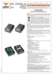
BARRIERA ALL'INFRAROSSO MODULATO - Cardin Elettronica
BARRIERA ALL'INFRAROSSO MODULATO - Cardin Elettronica
BARRIERA ALL'INFRAROSSO MODULATO - Cardin Elettronica

You also want an ePaper? Increase the reach of your titles
YUMPU automatically turns print PDFs into web optimized ePapers that Google loves.
mod: 25-06-2007<br />
CARDIN ELETTRONICA spa<br />
Via Raffaello, 36- 31020 San Vendemiano (TV) Italy<br />
Tel: +39/0438.404011-401818<br />
Fax: +39/0438.401831<br />
email (Italy):<br />
Sales.office.it@cardin.it<br />
email (Europe):<br />
Sales.office@cardin.it<br />
Http:<br />
www.cardin.it<br />
Descrizione<br />
Barriera all'infrarosso modulato composta da proiettore e ricevitore. Le apparecchiature<br />
sono alloggiate in un contenitore plastico antiurto a tenuta d'acqua con predisposizione<br />
per tutti i sistemi di fissaggio. L'ottica è regolabile su snodi frizionati e autobloccanti sia<br />
orizzontalmente, potendo compiere una rotazione di 90°, che verticalmente con una<br />
rotazione possibile di ± 30° rispetto alla posizione standard.<br />
Apparecchiatura a doppio relé con scambi in serie, il contatto NC è conforme alle norme<br />
di sicurezza EN12978, categoria 3 della EN954-1 e tipo 2 della EN61496-2.<br />
Possibilità di collegare un massimo di 3 coppie di fotocellule sincronizzando la trasmissione<br />
(sistema multiplexato).<br />
Possibilità d'impiego<br />
La barriera a raggio infrarosso rappresenta un efficiente sistema di sicurezza per la<br />
protezione di passaggi o spazi soggetti ad installazioni automatizzate di porte e cancelli<br />
controllati a distanza. L'uso e l'installazione di queste apparecchiature deve rispettare<br />
rigorosamente le indicazioni fornite dal costruttore e le norme di sicurezza vigenti.<br />
Versioni<br />
CDR973EX La confezione comprende gli elementi per l'applicazione in superficie<br />
- 1 proiettore; 1 ricevitore; 2 Vetrini di chiusura per fotocellule da esterno; 2 piastrine<br />
per fissaggio rapido a parete; serie di viterie e guarnizioni<br />
CDR973IX La confezione comprende gli elementi per l'applicazione ad incasso<br />
- 1 proiettore; 1 ricevitore; 2 contenitori da incasso; 2 vetrini di chiusura per fotocellule<br />
da incasso; serie di viterie e guarnizioni<br />
Accessori disponibili a richiesta<br />
CDR973ABC Protezione in materiale plastico antiurto (applicazioni in superficie, part.<br />
7, fig. 4).<br />
Caratteristiche tecniche<br />
- Emissione all'infrarosso con diodo GaAs (Arseniuro di Gallio), con portante a 25 kHz<br />
e modulante a 70 Hz.<br />
- Lunghezza d'onda dell'emissione infrarossa: 880 nm.<br />
- Alimentazione: 12 - 24V ac/dc.<br />
- Relé max potenza commutabile con carico resistivo:<br />
28W in dc/60VA in ac, tensione max 30V ac/dc; corrente max. 500 mA;<br />
- Tempo di intervento: 45 ms (singola fotocellula), 100 ms (sistema multiplexato)<br />
- Assorbimenti:<br />
12V ac/dc, 55 mA il ricevitore + 30 mA il proiettore;<br />
24V ac/dc, 60 mA il ricevitore + 30 mA il proiettore;<br />
- Temperatura di funzionamento: -10…+55 °C.<br />
- Grado di protezione IP55.<br />
- Portata: 30 m per impianti su interni di edifici<br />
15 m per impianti eseguiti all'esterno in tutte le condizioni, anche in<br />
presenza di fitta nebbia, pioggia, o polvere.<br />
Proiettore (fig. 2):<br />
- Selezione della tensione di alimentazione mediante ponticello "J3";<br />
- Led verde di segnalazione di rete;<br />
- DIP SWITCH "D2" per configurazione sistema multiplexato.<br />
Ricevitore (fig. 1):<br />
- Selezione della tensione di alimentazione mediante ponticello "J2";<br />
- Led verde di segnalazione fotocellula a riposo;<br />
- Led rosso acceso fisso: fotocellula non allineata o raggio interrotto;<br />
- Led rosso lampeggiante: fotocellula guasta;<br />
- Led arancione ad alta intensità (per centratura);<br />
- Deviatore "S1" per impostazione funzionamento normale o modalità centratura;<br />
- Test point (per centratura fine);<br />
- DIP SWITCH "D1" per configurazione sistema multiplexato e ritardo al rilascio;<br />
- Jumper "J1" per selezionare modalità contatto di uscita (NA/NC – NA/8,2 kΩ).<br />
Installazione<br />
Nota: In caso di installazioni comprendenti più apparecchiature è consigliabile realizzare<br />
una connessione a sistema multiplexato in modo da evitare interferenze fra le coppie<br />
di fotocellule.<br />
In tal caso, un proiettore è associato ad un ricevitore con impostazione dei DIP 1 e 2<br />
identica (DIP 3 viene ignorato).<br />
INSTALLAZIONE A SUPERFICIE CDR973EX (fig.4)<br />
• L'installazione consente oltre al posizionamento standard il posizionamento laterale<br />
(portando così le apparecchiature fuori della luce passaggio) e il posizionamento<br />
proiettore e ricevitore a quote differenziate (per superare problemi su strutture particolari)<br />
(part. a-b-c-d, fig.2).<br />
- Scegliere i punti di fissaggio a superficie in base alle necessità d'impianto.<br />
- Prevedere il percorso cavi sulla struttura fino ai punti di fissaggio.<br />
- Fissare le piastrine per l'attacco rapido nei punti stabiliti (part. 1 fig. 4).<br />
- Passare sull'apposito foro del contenitore base i cavi per i collegamenti.<br />
- Estrarre leggermente la scheda ed eseguire i collegamenti.<br />
- Collegata l'apparecchiatura inserire la guarnizione antiacqua ed eseguire l'accoppiamento<br />
a scatto tra base ad attacco rapido e contenitore base. Viene garantita<br />
l'impermeabilità dell'accoppiamento (part. 2, fig. 4).<br />
- Inserire nell'apposita sede del contenitore base la guarnizione di tenuta e procedere<br />
(dopo aver effettuato le opportune regolazioni) al fissaggio del vetrino (part. 5-6, fig. 4).<br />
- Se necessario prevedere l'installazione della mascherina di protezione, fornita a<br />
richiesta (part. 7, fig. 4).<br />
SERIAL NUMBER<br />
ZVL485.00<br />
<strong>BARRIERA</strong> <strong>ALL'INFRAROSSO</strong> <strong>MODULATO</strong><br />
SERIES<br />
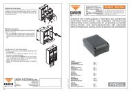
INSTALLAZIONE AD INCASSO CDR973IX (fig.5)<br />
- Scegliere i punti di incasso in base alla necessità d'impianto.<br />
- Prevedere le sedi d'incasso in base alle misure dei contenitori (part. 1, fig. 5).<br />
- Prevedere il percorso cavi sulla struttura fino ai punti d'incasso.<br />
- Passare i cavi sui contenitori inserirli a parete e fissarli nel modo più opportuno.<br />
- Passare sull'apposito foro del contenitore d'incasso i cavi per i collegamenti.<br />
- Estrarre leggermente la scheda ed eseguire i collegamenti.<br />
- Collegata l'apparecchiatura, eseguire l'accoppiamento tra contenitore ad incasso<br />
e contenitore base, premendo fino ad ottenere il giusto accoppiamento tra i piolini<br />
di riferimento ed i fori corrispondenti (part. 1-2. fig. 5).<br />
- Inserire nell'apposita sede del contenitore ad incasso la guarnizione di tenuta e<br />
procedere (dopo aver effettuato le opportune regolazioni) al fissaggio del vetrino<br />
(part. 4-5, fig. 5).<br />
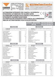
Connessioni e centratura<br />
- Eseguire le connessioni secondo lo schema (fig. 3), sfilando leggermente la scheda<br />
per facilitare l'operazione.<br />
- Impostare correttamente i ponticelli "J2" e "J3" (fig. 1, 2) a seconda dell’alimentazione<br />
utilizzata.<br />
- Impostare tutti i DIP SWITCH a OFF sia sul ricevitore sia sul proiettore<br />
- Impostare il deviatore "S1" del ricevitore in funzionamento normale (NORM)<br />
- Reinserire la scheda elettronica nelle apposite guide.<br />
- Alimentati proiettore e ricevitore risulterà: sul proiettore led verde acceso permanentemente<br />
e sul ricevitore acceso led rosso con fotocellula non centrata o acceso<br />
led verde con fotocellula centrata.<br />
- Sezione minima dei cavi di connessione: TX-RX = 0.2 mm 2 (AWG #24)<br />
Eseguire la centratura nel modo seguente:<br />
1) Impostare sul ricevitore il deviatore "S1" in posizione<br />
centratura "REG" (fig. 1): il led arancione ad alta<br />
intensità lampeggia in modo da indicare il grado di<br />
centratura; più tempo rimane acceso il led migliore<br />
è il centraggio delle ottiche.<br />
2) Orientare opportunamente l'ottica fino all’accensione<br />
permanente del led arancione (ricevitore). I dadi di<br />
regolazione sono frizionati ed autobloccanti, non<br />
devono pertanto essere ne serrati ne allentati.<br />
MODEL<br />
CDR 973 15-03-2006<br />
3) Per una centratura fine, usare un comune tester 2 Vdc fondoscala, inserendo i<br />
puntali nelle apposite zone di prova (vedi test point fig. 6) con l'esatta polarità<br />
come da contrassegni sul circuito stampato ed orientare opportunamente l'ottica<br />
fino ad ottenere il valore massimo di tensione prendendo come riferimento i valori<br />
riportati in tabella.<br />
4) Portare il deviatore "S1" in posizione "NORM": si accende il led verde nel ricevitore.<br />
Impostazioni sul ricevitore<br />
- Jumper inserito: impostazione del contatto di uscita (NA/NC).<br />
- Jumper disinserito: impostazione del contatto di uscita (NA/8,2 kΩ).<br />
- DIP 4 in posizione OFF: ritardo al rilascio 0,2 secondi.<br />
- DIP 4 in posizione ON: ritardo al rilascio 3 secondi.<br />
Sistema multiplexato<br />
- Posizionare tutti i proiettori sullo stesso lato.<br />
- Sui proiettori collegare in parallelo tutti gli ingressi<br />
SINC e collegare in parallelo tutti gli ingressi COM.<br />
- Alimentare e centrare le coppie di fotocellule una alla<br />
volta seguendo tutti i passi del paragrafo “connessioni<br />
e centratura”.<br />
- Eseguita separatamente la centratura di tutte le coppie<br />
di fotocellule, impostare su ciascuna coppia i DIP 1 e<br />
2 (proiettore e ricevitore) progressivamente secondo le<br />
configurazioni della tabella sotto riportata, partendo dalla<br />
prima che individua la coppia di fotocellule "master".<br />
- Alimentare tutte le coppie di fotocellule:<br />
sistema multiplexato configurato.<br />
DATE<br />
This product has been tried and tested in the manufacturer's laboratory, during<br />
the installation of the product follow the supplied indications carefully.<br />
Distanza Tensione<br />
(m) Test Point (V)<br />
3 1,8<br />
5 1,6<br />
8 1,3<br />
10 1,2<br />
12 1,1<br />
15 1,0<br />
COPPIA/DIP 1 2<br />
1 ON OFF<br />
2 OFF ON<br />
3 ON ON<br />
Corrente (mA) Anni<br />
100 5<br />
200 4<br />
300 3<br />
400 2<br />
500 1<br />
Manutenzione<br />
• Si consiglia di verificare il buon funzionamento dei relè alla scadenza riportata in<br />
tabella, calcolata sulla base della corrente di contatto.<br />
- Per calcolare le scadenze si è tenuto conto di circa 2000 attivazioni al giorno.<br />
Per effettuare la verifica procedere nel seguente modo:<br />
- disalimentare il ricevitore e prendere nota dello stato attuale dei 4 DIP SWITCH;<br />
- portare i 4 DIP a OFF;<br />
- portare il deviatore “S1” in posizione “REG”;<br />
- collegare i puntali di un comune tester rispettivamente all’uscita COM e all’uscita<br />
NC del ricevitore; impostare il tester in modalità “test continuità”;<br />
- alimentare il ricevitore e verificare che il tester segnali contatto aperto;<br />
- portare il DIP 1 in posizione ON: il tester deve sempre segnalare contatto aperto;<br />
- portare il DIP 1 in posizione OFF e il DIP 2 in posizione ON: il tester deve sempre<br />
segnalare contatto aperto;<br />
Se tutti i passi eseguiti hanno dato esito positivo è da ritenere che entrambi i relè<br />
funzionino correttamente.<br />
In caso contrario è necessario sostituire immediatamente il ricevitore. È severamente<br />
vietato utilizzare un ricevitore che non dia esito positivo alle prove sopra indicate.<br />
In caso di esito positivo:<br />
- disalimentare il ricevitore; scollegare il tester; riportare i DIP nello stato precedente<br />
alla manutenzione; portare il deviatore “S1” in posizione “NORM” e rialimentare il<br />
ricevitore.
Description<br />
Modulated infrared barrier consisting of a transmitter and a receiver.<br />
The equipment is housed in a shockproof and waterproof plastic casing.<br />
The adjustable lens, set on a self lubricating and self locking ball joint, can be adjusted<br />
through 90° horizontally and plus or minus 30° vertically.<br />
The equipment has a double relay with serial exchange and conforms to the safety directives<br />
EN12978 in category 3 of the EN954-1 and category 2 of the EN61496-2.<br />
It is possible to connect up to 3 pairs of photocells and synchronize the transmission<br />
(multiplex system).<br />
Use:<br />
The infrared barrier constitutes an efficient safety system for the protection of passageways<br />
or spaces which are equipped with automatic door or gate systems.<br />
The use and installation of these devices must respect the safety standards and<br />
regulations in force.<br />
MODULATED INFRARED BARRIER<br />
EMBEDDED INSTALLATIONS CDR973IX (fig. 5)<br />
- Choose the points at which the devices are to be surface mounted, according to<br />
the requirements of the system;<br />
- Excavate the seat for embedding according to the dimensions of the case (detail<br />
1, fig. 5);<br />
- Work out the run of the cables from the structure to the point of connection;<br />
- Pass the cables through the wall, through the embedding case "1" and fasten<br />
down;<br />
- Pass the connecting cables through the hole in the base of the "2" case;<br />
- Extract the PCB card gently then wire up and connect the cables;<br />
- Once the device has been wired up, insert the base case into the embedding case<br />
and press the two together until the reference pins coincide with the corresponding<br />
holes (detail 1-2, fig. 5);<br />
- Insert the sealing gasket into its seat on the case, carry out any eventual adjustments<br />
and then fit the glass enclosing cover into place (detail 4-5, fig. 5).<br />
Versions<br />
CDR973EX The package contains the components required for surface installations:<br />
- 1 transmitter ; 1 receiver; 2 glass enclosing covers for externally located photoelectric<br />
cells; 2 fast-fitting wall mounting brackets; set of screws and gaskets<br />
CDR973IX The package contains the components required for embedding:<br />
- 1 transmitter; 1 receiver; 2 embedding containers; 2 glass enclosing covers for<br />
embedded photoelectric cells; set of screws and gaskets<br />
Optional accessories<br />
CDR973ABC Shock-proof plastic protection (for surface flush fitting part 7. fig. 4)<br />
Technical specifications<br />
- Infrared emission obtained through the use of a double emitter GaAs (Galium<br />
Arsenide) diode with range 25 kHz and continuous modulation at 70 Hz;<br />
- Infrared emission wavelength: 880 nm;<br />
- Power supply: 12 - 24 Vac/dc;<br />
- Maximum commutable relay power with resistive load:<br />
28W in dc/60VA in ac; max. voltage 30 Vac/dc; max. current 500 mA<br />
- Intervention time: 45 ms (for a single pair of photocells); 100 ms (for a multiplex<br />
system)<br />
- Power consumption:<br />
12 Vac/dc, 55 mA for the receiver + 30 mA for the transmitter<br />
24 Vac/dc, 60 mA for the receiver + 30 mA for the transmitter<br />
- Operating temperature: -10…+55°C;<br />
- Protection grade IP55<br />
- Range:<br />
30 m for internal installations;<br />
15 m for external installations under all weather conditions such as thick fog, rain<br />
and dust etc.<br />
Transmitter (fig. 2):<br />
- Power supply voltage selection by means of the jumper "J3";<br />
- Green power on led;<br />
- Dip-switch "D2" multiplex installation settings.<br />
Receiver (fig. 1):<br />
- Power supply voltage selection by means of the jumper "J2";<br />
- Green led indicating photoelectric unbroken beam;<br />
- Red led lit continuously: photoelectric beam disturbed or misaligned;<br />
- Red led lit flashing: photoelectric beam not functioning;<br />
- High intensity orange led for centring ;<br />
- Switch "S1" selection between normal operation or centring mode;<br />
- Test point for fine tuning;<br />
- Dip-switch "D1" multiplex installation settings and relay delay mode;<br />
- Jumper "J1" for selecting the output mode (NA/NC – NA/8,2 kΩ).<br />
Installation<br />
Note: In cases where the installation consists of more than one device you are advised<br />
to use the multiplex function so as to avoid interference between the beams. In this<br />
case each transmitter is associated with a receiver by setting dips 1 and 2 identically<br />
(Dip 3 is ignored).<br />
Surface MOUNTED installations CDR973EX (fig. 4)<br />
• Other than the standard aligned positioning the CDR 973/E can also be positioned<br />
both laterally (moving the device out of the passageway) and at different heights in<br />
order to solve problems posed by different structures ( detail a-b-c-d, fig. 2)<br />
- Choose the points at which the devices are to be surface mounted, according to<br />
the requirements of the system;<br />
- Work out the run of the cables from the structure to the point of connection;<br />
- Fix the fast-fitting brackets at the chosen points (detail 1, fig. 4);<br />
- Pass the connecting cables through the hole in the base of the case;<br />
- Move the p.c.b. card slightly then wire up and connect the cables;<br />
- Once the device has been wired up, snap the case to the fast-fitting bracket,<br />
remembering to place the waterproof seal between the case and the bracket. The<br />
joint between the case and the bracket is guaranteed to be waterproof (detail 2,<br />
fig. 4);<br />
- Insert the sealing gasket into its seat on the case, carry out any eventual adjustments<br />
and then fit the glass enclosing cover into place (detail 5-6, fig. 4);<br />
- If required fit the optional protective covering which is available on request (detail<br />
7, fig. 4).<br />
Connections and centring<br />
- Wire up the device according to the indications shown in figures 1 and 2.<br />
- Set jumpers "1" and "2" correctly according to the required voltage.<br />
- Set all dips to the "off" position both on the receiver as well as on the transmitter.<br />
- Set the switch "S1" to normal operation (NORM).<br />
- Replace the p.c.b. card;<br />
- Once the power has been turned on the following will occur:<br />
the transmitter led will remain permanently lit and, if the receiver is not aligned, the<br />
receiver led will also be lit.<br />
- The minimum cable cross section area for the transmitter/receiver is:<br />
= 0,2 mm 2 (AWG #24)<br />
Centring should be carried out as follows:<br />
1) Move the switch "S1" on the receiver to the position<br />
"REG" (fig. 1): the orange high intensity led will flash<br />
indicating the degree of centring. The longer the led<br />
remains lit the better tuned the photoelectric cell is.<br />
2) Orientate the lens until the orange receiver led remains<br />
permanently lit. The lenses are self-lubricating and<br />
self-locking and therefore do not have to be tightened<br />
or loosened.<br />
3) To obtain fine centring use a normal tester (lowest setting 2V dc). Place the probes<br />
over the test point (fig. 6) maintaining the correct polarity as indicated on the p.c.b.<br />
card and orientate the lens according to the distance/test point table.<br />
4) Move the switch "S1" on the receiver to the position "NORM" (fig. 1): the green led<br />
on the receiver will light up.<br />
Receiver settings<br />
- Jumper inserted: setting the output contacts to NO/NC<br />
- Jumper disinserted: setting the output contacts to NA/8,2 kΩ<br />
- DIP 4 in the "Off" position: relay delay of 0,2 seconds<br />
- DIP 4 in the "On" position: relay delay of 3 seconds<br />
Multiplex system<br />
- Position all the transmitters on the same side.<br />
- Connect all the SINC inputs on the receivers in parallel<br />
and connect the COM inputs in parallel;<br />
- Power up the pairs of photoelectric cells and centre<br />
them by following the paragraph "Connections and<br />
centring";<br />
- Carry out the centring procedure separately for each pair<br />
of photoelectric cells. Set the dips 1 and 2 on each pair of<br />
photoelectric cells (transmitter and receiver) progressively<br />
according to the configuration laid out in the table on the<br />
right and starting from the master photoelectric cell.<br />
- Power up all the pairs of photoelectric cells and you have<br />
finished setting the multiplex installation.<br />
Distance<br />
(m)<br />
Test point<br />
Voltage (V)<br />
3 1.8<br />
5 1.6<br />
8 1.3<br />
10 1.2<br />
12 1.1<br />
15 1.0<br />
PAIR/DIP 1 2<br />
1 ON OFF<br />
2 OFF ON<br />
3 ON ON<br />
Current (mA) Years<br />
100 5<br />
200 4<br />
300 3<br />
400 2<br />
500 1<br />
Maintenance<br />
• You are advised to check the condition of the relays at the time interval in the table<br />
depending on the current present on the relay's contacts.<br />
- To calculate the time period we took into account 2000 relay activations per day.<br />
To test the relays proceed as follows:<br />
- switch off the receiver and write down the position of the four dips;<br />
- move the 4 DIPs to OFF;<br />
- move the switch “S1” to the position “REG”;<br />
- connect the contacts of a common tester to the outputs COM and NC on the<br />
receiver; set the tester to the “continuity test” mode;<br />
- power up the receiver and check that the tester indicates open contacts;<br />
- move DIP 1 to ON: the tester must still indicate open contacts;<br />
- move DIP 1 to OFF and DIP 2 to ON: the tester must still indicate open contacts.<br />
If all the steps gave positive results then both relays are deemed to be functioning<br />
correctly.<br />
If this is not the case you will have to replace the receiver immediately. It is forbidden<br />
to use a receiver that has not passed the above mentioned test.<br />
If the test gave you a positive outcome:<br />
- switch off the receiver; disconnect the tester; move the DIPs back to the positions<br />
they were originally in before the maintenance test; move switch “S1” to the position<br />
“NORM” and power up the receiver.
Descriptif<br />
Barrage à l'infrarouge modulé, constitué d'un émetteur et d'un récepteur logés sous<br />
boîtiers plastiques antichoc et étanches, prédisposés pour tous les systèmes de fixation.<br />
La tête optique, montée sur pivot orientable et autobloquant, est réglable horizontalement<br />
par rotation de 90°, et verticalement par rotation de ± 30° par rapport à la position<br />
standard. Appareil à double relais avec contact inverseur en série. Le contact N.F. est<br />
conforme aux normes de sécurité EN12978, catégorie 3 de la norme EN954-1 et type<br />
2 de la norme EN61496-2.<br />
Possibilité de raccorder un maximum de 3 couples de cellules photoélectriques par<br />
synchronisation de l'émission (système multiplexé).<br />
Domaine d'application<br />
Le barrage à rayon infrarouge est destiné à assurer efficacement la sécurité des personnes<br />
et des biens lors de l'actionnement d'un système de fermeture automatique.<br />
Pour l'utilisation et la pose de ces appareils, se conformer rigoureusement aux instructions<br />
fournies par le Fabricant et aux normes de sécurité en vigueur.<br />
Versions<br />
CDR973EX La boîte contient tous les éléments nécessaires à une application en<br />
saillie.<br />
- 1 émetteur; 1 récepteur; 2 verres de protection pour cellules photoélectriques en<br />
saillie; 2 plaques de fixation rapide au mur; un jeu de vis et de joints<br />
CDR973IX La boîte contient tous les éléments nécessaires à une application en<br />
encastré.<br />
- 1 émetteur; 1 récepteur; 2 boîtiers d'encastrement; 2 verres de protection pour cellules<br />
photoélectriques en encastré; un jeu de vis et de joints<br />
Accessoires en option<br />
CDR973ABC Protection en matière plastique antichoc (applications en saillie, dét. 7,<br />
fig. 4).<br />
Caractéristiques techniques<br />
- Émission infrarouge par diode GaAs (arséniure de gallium), avec porteuse à 25 kHz<br />
et modulation à 70 Hz.<br />
- Longueur d'onde de l'émission infrarouge: 880 nm.<br />
- Alimentation: 12 - 24V ac/dc.<br />
- Consommation maximale de commutation du relais avec charge résistive:<br />
28W en dc/60VA en ac, tension maxi. 30V ac/dc; courant maxi. 500 mA;<br />
- Temps d'intervention: 45 ms (couple de cellules photoélectriques), 100 ms (système<br />
multiplexé)<br />
- Intensité absorbée:<br />
en 12V ac/dc, 55 mA le récepteur + 30 mA l'émetteur,<br />
en 24V ac/dc, 60 mA le récepteur + 30 mA l'émetteur.<br />
- Température de fonctionnement: -10…+55 °C.<br />
- Indice de protection IP55.<br />
- Portée:<br />
30 m pour installations se trouvant à l'intérieur d'édifices<br />
15 m pour installations se trouvant à l'extérieur, quelles que soient les conditions climatiques<br />
et environnantes, brouillard épais, pluie ou poussière.<br />
Émetteur (fig. 2)<br />
- Sélection de la tension d'alimentation par cavalier "J3".<br />
- Led verte de signalisation de mise sous tension.<br />
- DIP-SWITCH "D2" pour configuration du système multiplexé.<br />
Récepteur (fig. 1)<br />
- Sélection de la tension d'alimentation par cavalier "J2".<br />
- Led verte de signalisation cellule photoélectrique en veille.<br />
- Led rouge allumée fixe: cellule photoélectrique non alignée ou occultée.<br />
- Led rouge clignotante: cellule photoélectrique défectueuse.<br />
- Led orange à haute intensité (pour centrage).<br />
- Déviateur "S1" pour établir le fonctionnement normal ou le procédé de centrage.<br />
- Test point (pour centrage de précision).<br />
- DIP-SWITCH "D1" pour la configuration du système multiplexé et temps de désexcitation.<br />
- Cavalier "J1" pour la sélection du mode de fonctionnement du contact de sortie<br />
(NO/NF – NO/8,2 kΩ).<br />
Pose<br />
Nota: en cas d'installation comprenant plusieurs appareils, il est conseillé de mettre en<br />
œuvre le système multiplexé, afin de parer aux risques d'interférence entre les différents<br />
couples de cellules photoélectriques.<br />
Dans ce cas, un émetteur est associé à un récepteur en configurant les DIPS 1 et 2 de<br />
la même façon (DIP 3 peut être ignoré).<br />
MONTAGE EN SAILLIE CDR973EX (fig. 4)<br />
• Les appareils peuvent être appliqués aussi bien en position standard qu'en position<br />
latérale (ce qui permet de les déporter par rapport au passage) et à des hauteurs<br />
différentes l'un par rapport à l'autre (pour solutionner les problèmes sur structures<br />
particulières) (détails a-b-c-d, fig. 2).<br />
- Déterminer les points de fixation en saillie en fonction de la particularité de l'installation.<br />
- Prévoir le chemin des câbles sur la structure jusqu'aux points de fixation.<br />
- Fixer les plaques pour la fixation rapide aux endroits déterminés auparavant (dét.<br />
1 fig. 4).<br />
- Faire passer les câbles de branchement à travers le trou prévu sur le boîtier de base.<br />
- Dégager un peu la carte de son logement et effectuer les branchements.<br />
- Une fois l'appareil branché, appliquer le joint d'étanchéité et emboîter le boîtier de<br />
base sur la plaque de fixation rapide. Pour garantir l'étanchéité, veiller à la mise en<br />
place correcte du joint (dét. 2, fig. 4).<br />
- Introduire le joint d'étanchéité dans le logement prévu sur le boîtier de base et<br />
fixer le verre après avoir effectué tous les réglages qui s'imposent (dét. 5-6, fig. 4).<br />
- Si nécessaire, monter la protection en option, fournie sur demande (dét. 7, fig. 4).<br />
BARRIERE A L'INFRAROUGE MODULE<br />
MONTAGE EN ENCASTRÉ CDR973IX (fig. 5)<br />
- Déterminer les poins d'encastrement en fonction de la particularité de l'installation.<br />
- Réaliser les cavités pour l'encastrement en fonction des dimensions des boîtiers<br />
(dét. 1, fig. 5).<br />
- Prévoir le chemin des câbles sur la structure jusqu'aux points d'encastrement.<br />
- Faire passer les câbles dans le boîtier, encastrer celui-ci dans la cavité et le fixer<br />
convenablement.<br />
- Faire passer les câbles de branchement à travers le trou qui se trouve sur le boîtier<br />
d'encastrement.<br />
- Dégager un peu la carte de son logement et effectuer les branchements.<br />
- Une fois l'appareil branché, appliquer le boîtier d'encastrement sur le boîtier de<br />
base en exerçant une pression jusqu'à ce que les taquets s'enclenchent dans les<br />
trous correspondants (part. 1-2. fig. 5).<br />
- Introduire le joint d'étanchéité dans le logement prévu sur le boîtier d'encastrement<br />
et fixer le verre (dét. 4-5, fig. 5) après avoir effectué tous les réglages qui s'imposent.<br />
Connexions et centrage<br />
- Effectuer les connexions suivant le schéma (fig. 3) après avoir dégagé la carte pour<br />
faciliter le travail.<br />
- Configurer les cavaliers "J2" et "J3" (fig. 1, 2) selon l'alimentation utilisée.<br />
- Placer sur OFF tous les DIP-SWITCHES qui se trouvent sur l'émetteur et sur le<br />
récepteur.<br />
- Placer le déviateur "S1" du récepteur sur fonctionnement normal (NORM).<br />
- Remettre la carte électronique à sa place sur les glissières.<br />
- Une fois que l'émetteur et le récepteur sont sous tension, la led verte sur l'émetteur<br />
est allumée en permanence et, sur le récepteur, la led rouge allumée indique que<br />
les cellules photoélectriques ne sont pas alignées, et la led verte allumée qu'elles<br />
sont alignées.<br />
- La section minimum des câbles de branchement de l'émetteur et du récepteur est<br />
de 0,2 mm 2 (AWG #24).<br />
Effectuer le centrage de la façon suivante:<br />
1) Placer le déviateur, sur le récepteur, en position de<br />
centrage "REG" (fig. 1): la led orange à haute intensité<br />
se met à clignoter pour indiquer le niveau de centrage;<br />
plus longtemps la led reste allumée et plus précis est<br />
le centrage des têtes optiques.<br />
2) Orienter la tête optique de manière à ce que la led<br />
orange (récepteur) reste allumée en permanence. Les<br />
pivots de réglage étant orientables et autobloquants,<br />
ils ne peuvent être ni serrés, ni desserrés.<br />
3) Pour un centrage de précision, utiliser un testeur normal 2 Vdc échelle maximum, et<br />
introduire les pointes aux endroits de contrôle (voir test point fig. 6) en respectant la<br />
polarité marquée sur le circuit imprimé; ensuite, orienter la tête optique de manière<br />
à obtenir une tension maximum en prenant comme référence les valeurs indiquées<br />
au tableau.<br />
4) Placer le déviateur "S1" en position "NORM"; la led verte sur le récepteur s'allume.<br />
Configurations sur le récepteur<br />
- Cavalier connecté: configuration du contact de sortie (NO/NF)<br />
- Cavalier déconnecté: configuration du contact de sortie (NO/8,2 kΩ)<br />
- DIP 4 en position OFF: temps de désexcitation 0,2 seconde<br />
- DIP 4 en position ON: temps de désexcitation 3 secondes<br />
Système multiplexé<br />
- Placer tous les émetteurs du même côté.<br />
- Sur les émetteurs, brancher en parallèle toutes les<br />
entrées SINC et brancher en parallèle toutes les entrées<br />
COM.<br />
- Mettre sous tension et aligner les couples de cellules<br />
photoélectriques l'un après l'autre en observant toutes<br />
les étapes du paragraphe “Connexions et centrage”.<br />
- Une fois que le centrage de tous les couples de cellules<br />
photoélectriques a été effectué l'un après l'autre, configurer<br />
sur chaque couple les DIPS 1 et 2 (émetteur et récepteur)<br />
progressivement selon les configurations du tableau cidessous<br />
en partant du premier qui représente le couple<br />
de cellules photoélectriques "master".<br />
- Alimenter tous les couples de cellules photoélectriques:<br />
système multiplexé configuré.<br />
Distanca Valeur<br />
(m) Test Point (V)<br />
3 1,8<br />
5 1,6<br />
8 1,3<br />
10 1,2<br />
12 1,1<br />
15 1,0<br />
COUPLE/DIP 1 2<br />
1 ON OFF<br />
2 OFF ON<br />
3 ON ON<br />
Courant (mA) Années<br />
100 5<br />
200 4<br />
300 3<br />
400 2<br />
500 1<br />
Maintenance<br />
• Il est conseillé de contrôler le bon fonctionnement des relais à l’échéance indiquée<br />
au tableau et calculée en fonction du courant de contact.<br />
- Ces échéances ont été calculées en considérant 2000 actionnements environ par<br />
jour.<br />
Pour effectuer le contrôle, procéder de la façon suivante:<br />
- mettre le récepteur hors tension et prendre note de la configuration actuelle des 4<br />
DIP-SWITCHES;<br />
- placer les 4 DIPS sur OFF;<br />
- placer le déviateur “S1” en position “REG”;<br />
- brancher les pointes d’un testeur normal respectivement à la sortie COM et à la sortie<br />
NF du récepteur; régler le testeur sur mode “test continuité”;<br />
- mettre le récepteur sous tension et vérifier que le testeur signale contact ouvert;<br />
- placer le DIP 1 sur ON; le testeur doit toujours signaler contact ouvert;<br />
- placer le DIP 1 sur OFF et le DIP 2 sur ON; le testeur doit toujours signaler contact ouvert.<br />
Si le résultat des contrôles effectués à toutes ces étapes est positif, on peut en déduire<br />
que les deux relais fonctionnent correctement.<br />
Au cas contraire, il est impératif de remplacer immédiatement le récepteur. Il est absolument<br />
interdit d’utiliser un récepteur qui s’avère défaillant aux contrôles susmentionnés.<br />
En cas de résultat positif:<br />
- mettre le récepteur hors tension; débrancher le testeur; replacer les DIPS dans la<br />
configuration qu’ils avaient avant de procéder au contrôle; placer le déviateur “S1”<br />
en position “NORM” et remettre sous tension le récepteur.
Beschreibung<br />
Modulierte Infrarotlichtschranke bestehend aus Sender und Empfänger. Die Geräte<br />
sind in einem stoßfesten und wasserdichten Kunststoffgehäuse mit Vorrüstung für alle<br />
Befestigungssysteme untergebracht. Die Optik kann auf Brems-Selbstblockiergelenken<br />
horizontal über eine Drehung um 90° als auch vertikal durch eine mögliche Drehung<br />
um ± 30° gegenüber der Standardposition orientiert werden.<br />
Gerät mit doppeltem Relais mit Austausch in Serie, der NC-Kontakt entspricht den<br />
Sicherheitsvorschriften EN12978, Kategorie 3 der EN954-1 und Typ 2 der EN61496-2.<br />
Möglichkeit zum Anschluss von maximal 3 Lichtschrankenpaaren mit Synchronisierung<br />
der Übertragung (Multiplex-System).<br />
Einsatzmöglichkeit<br />
Die Infrarotlichtschranke stellt ein wirksames Sicherheitssystem zum Schutz von<br />
Durchgängen oder Flächen dar, bei denen automatische Türen oder ferngesteuerte<br />
Tore installiert werden. Bei der Benutzung und Installation dieser Geräte sind die Herstelleranweisungen<br />
und die geltenden Sicherheitsvorschriften streng zu befolgen.<br />
Ausführungen<br />
CDR973EX Die Packung enthält die Elemente für die Aufputzanbringung<br />
- 1 Sender; 1 Empfänger; 2 Verschlussgläschen für Lichtschranken zur Außenanbringung;<br />
2 Plättchen für die Wandschnellbefestigung; Schrauben- und Dichtungsset<br />
CDR973IX Die Packung enthält die Elemente für die Unterputzanbringung<br />
- 1 Sender; 1 Empfänger; 2 Unterputzgehäuse; 2 Verschlussgläschen für Unterputz-<br />
Lichtschranken; Schrauben- und Dichtungsset<br />
Auf Anfrage lieferbares Zubehör<br />
CDR973ABC Schutzvorrichtung aus stoßfestem Kunststoff (Aufputzanbringung,<br />
Detail. 7, Abb. 4).<br />
Technische Eigenschaften<br />
- Infrarotstrahlung mit GaAs-Diode (Galliumarsenid), mit Träger auf 25 kHz und<br />
Modulation auf 70 Hz.<br />
- Wellenlänge der Infrarotstrahlung: 880 nm.<br />
- Stromversorgung: 12 - 24V ac/dc.<br />
- Max. Umschaltleistung des Relais bei Widerstandsbelastung:<br />
28W in dc/60VA in ac, Höchstspannung 30V ac/dc; Höchststrom 500 mA;<br />
- Ansprechzeit: 45 ms (Lichtschrankenpaar), 100 ms (Multiplex-System)<br />
- Aufnahmen:<br />
12V ac/dc, 55 mA der Empfänger + 30 mA der Sender;<br />
24V ac/dc, 60 mA der Empfänger + 30 mA der Sender;<br />
- Betriebstemperatur: -10…+55 °C;<br />
- Schutzgrad IP55.<br />
- Reichweite:<br />
30 m für Anlagen im Gebäudeinneren<br />
15 m für Außenanlagen unter allen Bedingungen, auch bei dichtem Nebel, Regen<br />
oder Staub.<br />
Sender (Abb. 2):<br />
- Auswahl der Versorgungsspannung über Überbrückung "J3";<br />
- Grünes Led zur Anzeige anliegender Spannung;<br />
- DIP-SWITCH "D2" für die Multiplex-System-Konfiguration.<br />
Empfänger (Abb. 1):<br />
- Auswahl der Versorgungsspannung über Überbrückung "J2";<br />
- Grünes Led zur Anzeige Lichtschranke in Ruhestellung;<br />
- Dauerleuchtendes rotes Led: Lichtschranke nicht ausgerichtet oder Strahl unterbrochen;<br />
- Blinkendes rotes Led: Lichtschranke defekt;<br />
- Orange Led mit hoher Intensität (für Zentrierung);<br />
- Wechselschalter "S1" für die Einstellung des Normalbetriebs oder Zentrierverfahrens;<br />
- Test Point (für Feinzentrierung);<br />
- DIP-SWITCH "D1" für Multiplex-System-Konfiguration und Entregungsverzögerung;<br />
- Jumper "J1" für die Auswahl der Funktionsmodalität des Ausgangskontakts (NO/NC<br />
– NO/8,2 kΩ).<br />
Installation<br />
Hinweis: Bei Installationen, die mehrere Geräte umfassen, sollte ein Anschluss als<br />
Multiplex-System erfolgen, um Störungen zwischen den Lichtschrankenpaaren zu<br />
vermeiden. In diesem Fall ist ein Sender mit einem Empfänger mit identischer Einstellung<br />
der DIP 1 und 2 verbunden (DIP 3 wird ignoriert).<br />
AUFPUTZINSTALLATION CDR973EX (Abb. 4)<br />
• Die Installation erlaubt über die Standardpositionierung hinaus die seitliche Positionierung<br />
(und bringt so die Geräte aus dem Durchgang) und die Positionierung<br />
von Sender und Empfänger auf unterschiedlichen Höhen (um besondere Strukturprobleme<br />
zu überwinden) (Detail. a-b-c-d, Abb. 2).<br />
- Die Aufputz-Befestigungspunkte nach den Anlagenanforderungen auswählen.<br />
- Den Kabelverlauf auf der Struktur bis zu den Befestigungspunkten vorsehen.<br />
- Die Plättchen für die Schnellverbindung an den ausgewählten Punkten befestigen<br />
(Detail 1, Abb. 4).<br />
- Die Anschlusskabel durch die dafür vorgesehene Öffnung des Basisgehäuses<br />
führen.<br />
- Die Karte etwas herausziehen und die Anschlüsse vornehmen.<br />
- Nach Anschluss des Geräts die Wasserschutzdichtung einführen und die Schnappverbindung<br />
zwischen Schnellverbindungsbasis und Basisgehäuse vornehmen. Die<br />
Wasserdichtheit der Verbindung wird garantiert (Detail 2, Abb. 4).<br />
- In den dafür vorgesehenen Sitz des Basisgehäuses die Dichtung einsetzen und<br />
mit der Befestigung des Gläschens fortfahren (nach Durchführung der nötigen<br />
Einstellungen) (Detail 5-6, Abb. 4).<br />
- Wenn nötig die auf Anfrage gelieferte Schutzblende installieren (Detail 7, Abb. 4).<br />
MODULIERTE INFRAROTLICHTSCHRANKE<br />
UNTERPUTZINSTALLATION CDR973IX (Abb. 5)<br />
- Die Unterputzpunkte nach den Anlagenanforderungen auswählen.<br />
- Die Unterputzsitze auf der Grundlage der Gehäusemaße vorsehen (Detail 1, Abb. 5).<br />
- Den Kabelverlauf auf der Struktur bis zu den Befestigungspunkten vorsehen.<br />
- Die Kabel auf die Gehäuse führen, in die Wand einführen und richtig befestigen.<br />
- Die Anschlusskabel durch die dafür vorgesehene Öffnung des Unterputzgehäuses<br />
führen.<br />
- Die Karte etwas herausziehen und die Anschlüsse vornehmen.<br />
- Nach Anschluss des Geräts die Verbindung zwischen Unterputzgehäuse und Basisgehäuse<br />
vornehmen, indem so lange gedrückt wird, bis die richtige Verbindung zwischen<br />
den Referenzstiften und den entsprechenden Öffnungen erreicht ist (Detail 1-2, Abb. 5).<br />
- In den dafür vorgesehenen Sitz des Unterputzgehäuses die Dichtung einsetzen<br />
und mit der Befestigung des Gläschens fortfahren (nach Durchführung der nötigen<br />
Einstellungen) (Detail 4-5, Abb. 5).<br />
Anschlüsse und Zentrierung<br />
- Die Anschlüsse nach Plan (Abb. 3) vornehmen, indem die Karte etwas herausgezogen<br />
wird, um den Arbeitsgang zu erleichtern.<br />
- Die Überbrückungen "J2" und "J3" (Abb. 1, 2) je nach benutzter Stromversorgung<br />
richtig einstellen.<br />
- Alle DIP-SWITCH an Empfänger und Sender auf OFF stellen.<br />
- Den Wechselschalter "S1" des Empfängers auf Normalbetrieb (NORM) einstellen.<br />
- Die elektronische Karte wieder in die dafür vorgesehenen Führungen einführen.<br />
- Nach Stromversorgung von Sender und Empfänger ist: am Sender das grüne Led dauerhaft<br />
eingeschaltet und am Empfänger das rote Led bei nicht zentrierter Lichtschranke<br />
eingeschaltet oder das grüne Led bei zentrierter Lichtschranke eingeschaltet.<br />
- Mindestquerschnitt der Anschlusskabel: TX-RX = 0.2 mm2 (AWG #24).<br />
Die Zentrierung folgendermaßen durchführen:<br />
1) Am Empfänger den Wechselschalter "S1" auf Zentrierposition<br />
"REG" (Abb. 1) stellen: Das orange Led<br />
mit hoher Intensität blinkt, um den Grad der Zentrierung<br />
anzuzeigen; je länger das Led eingeschaltet<br />
bleibt, desto besser ist die Zentrierung der Optiken.<br />
2) Die Optik orientieren, bis das orange Led dauerhaft<br />
eingeschaltet bleibt (Empfänger). Die Reguliergelenke<br />
sind gebremst und selbstblockierend und müssen<br />
daher weder angezogen noch gelöst werden.<br />
3) Für die Feinzentrierung einen handelsüblichen Tester mit 2Vdc Vollausschlag<br />
benutzen, indem die Prüfspitzen mit der richtigen Polarität wie auf der gedruckten<br />
Schaltung angegeben in die dafür vorgesehenen Prüfbereiche eingesetzt werden<br />
(siehe Test Point Abb. 6), und die Optik bis zur Erreichung einer maximale Spannung<br />
wobei als Bezug die in der Tabelle aufgeführten Werte zu betrachten sind.<br />
4) Den Wechselschalter "S1" in die Position "NORM" bringen: Das grüne Led des<br />
Empfängers schaltet sich ein.<br />
Einstellungen am Empfänger<br />
- Jumper angeschlossen: Einstellung des Ausgangskontakts (NO/NC)<br />
- Jumper nicht angeschlossen: Einstellung des Ausgangskontakts (NO/8,2 kΩ)<br />
- DIP 4 in Position OFF: Entregungsverzögerung 0,2 Sekunden<br />
- DIP 4 in Position ON: Entregungsverzögerung 3 Sekunden<br />
Multiplex-System<br />
- Alle Sender auf derselben Seite positionieren.<br />
- An den Sendern parallel alle SINC-Eingänge anschließen<br />
und parallel alle COM-Eingänge anschließen.<br />
- Die Lichtschrankenpaare nacheinander mit Strom<br />
versorgen und zentrieren, wobei alle Schritte des Abschnitts<br />
“Anschlüsse und Zentrierung” zu befolgen sind.<br />
- Nachdem die Zentrierung aller Lichtschrankenpaare einzeln<br />
ausgeführt wurde, an jedem Paar die DIP 1 und 2 (Sender<br />
und Empfänger) fortschreitend nach den Konfigurationen der<br />
unten aufgeführten Tabelle einstellen, wobei bei der ersten anzufangen<br />
ist, die das "Master"-Lichtschrankenpaar bestimmt.<br />
- Alle Lichtschrankenpaare mit Strom versorgen:<br />
Mutiplex-System konfiguriert.<br />
Abstand Wert<br />
(m) Test Point (V)<br />
3 1,8<br />
5 1,6<br />
8 1,3<br />
10 1,2<br />
12 1,1<br />
15 1,0<br />
PAAR/DIP 1 2<br />
1 ON OFF<br />
2 OFF ON<br />
3 ON ON<br />
Strom (mA) Jahre<br />
100 5<br />
200 4<br />
300 3<br />
400 2<br />
500 1<br />
Wartung<br />
• Es wird empfohlen, das korrekte Funktionieren der Relais zu den in der Tabelle<br />
angegebenen Fälligkeiten zu kontrollieren, die berechnet wurden auf der Grundlage<br />
des Kontaktstroms.<br />
- Für die Berechnung der Fälligkeiten wurde von ca. 2000 Aktivierungen täglich ausgegangen.<br />
Für die Durchführung der Kontrolle ist auf folgende Weise vorzugehen:<br />
- Die Stromversorgung des Empfängers unterbrechen und sich den aktuellen Zustand<br />
der 4 DIP-SCHALTER notieren.<br />
- Die 4 DIP-SCHALTER auf OFF stellen.<br />
- Den Wechselschalter “S1” in die Position “REG” bringen.<br />
- Die Spitzen eines handelsüblichen Testers jeweils an den Ausgang COM und<br />
an den Ausgang NC des Empfängers anschließen; den Tester auf die Modalität<br />
“Durchgangsprüfung” einstellen.<br />
- Den Empfänger mit Strom versorgen und sicherstellen, dass der Tester einen offenen<br />
Kontakt anzeigt.<br />
- Den DIP-SCHALTER 1 in die Position ON bringen: Der Tester muss stets einen<br />
offenen Kontakt anzeigen.<br />
- Den DIP-SCHALTER 1 in die Position OFF und den DIP SWITCH 2 in die Position<br />
ON bringen: Der Tester muss stets einen offenen Kontakt anzeigen.<br />
Wurden alle Arbeitsschritte mit positivem Ergebnis ausgeführt, ist davon auszugehen,<br />
dass beide Relais korrekt funktionieren. Anderenfalls muss der Empfänger unverzüglich<br />
ausgetauscht werden. Es ist streng verboten, einen Empfänger zu benutzen, der bei<br />
den oben aufgeführten Prüfungen kein positives Ergebnis erzielt hat.<br />
Bei einem positiven Ergebnis:<br />
- die Stromversorgung zum Empfänger unterbrechen; den Tester abnehmen; die DIP<br />
SWITCH in den Zustand vor der Wartung zurückbringen; den Wechselschalter “S1”<br />
in die Position “NORM” bringen und den Empfänger wieder mit Strom versorgen.
Descripción<br />
Barrera de rayos infrarrojos modulada compuesta por emisor y receptor. Los aparatos<br />
están alojados en una caja de plástico antichoque estanca al agua con predisposición<br />
para todos los sistemas de fijación. La óptica es ajustable en articulaciones friccionadas<br />
y de autobloqueo, tanto horizontalmente, pudiendo realizar una rotación de 90°, como<br />
verticalmente con una rotación posible de ±30° respecto a la posición estándar.<br />
Aparato con doble relé e intercambios de serie; el contacto NC es conforme a las<br />
normas de seguridad EN12978, categoría 3 de la EN954-1 y tipo 2 de la EN61496-<br />
2. Posibilidad de conectar un máximo de 3 parejas de fotocélulas, sincronizando la<br />
transmisión (sistema multiplexado).<br />
Posibilidades de uso<br />
La barrera de rayos infrarrojos representa un sistema di seguridad eficaz para la<br />
protección de las aberturas de paso o espacios sujetos a instalaciones automatizadas<br />
de puertas y cancillas controladas a distancia.<br />
El uso y la instalación de estos aparatos debe cumplir estrictamente con las indicaciones<br />
proporcionadas por el fabricante y las normas de seguridad en vigor.<br />
Versiones<br />
CDR973EX El aparato incluye los siguientes componentes para la aplicación en<br />
superficie:<br />
- 1 emisor; 1 receptor; 2 cristales de cierre para fotocélulas para exteriores; 2 plaquitas<br />
para la fijación rápida de pared; juego de tornillería y juntas<br />
CDR973IX El aparato incluye los siguientes componentes para la aplicación empotrable:<br />
- 1 emisor; 1 receptor; 2 cajas empotrables; 2 cristales de cierre para fotocélulas<br />
empotrables; juego de tornillería y juntas<br />
Accesorios disponibles bajo solicitud<br />
CDR973ABC Protección de material plástico antichoque<br />
(aplicaciones en superficie, part. 7, fig. 4).<br />
Características técnicas<br />
- Emisión de rayos infrarrojos con diodo GaAs (Arseniuro de Galio), con alcance de<br />
25 kHz y modulación de 70 Hz.<br />
- Longitud de onda de la emisión de rayos infrarrojos: 880 nm.<br />
- Alimentación: 12 - 24V ac/dc.<br />
- Consumo máximo de conmutación del relé con carga resistiva:<br />
28W de dc/60VA de ac, voltaje máx. 30V ac/dc; corriente máx. 500 mA;<br />
- Tiempo de actuación: 45 ms (por pareja de fotocélulas: emisor y receptor), 100<br />
ms (sistema de multiplexado)<br />
- Absorciones:<br />
12V ac/dc, 55 mA el receptor + 30 mA el emisor;<br />
24V ac/dc, 60 mA el receptor + 30 mA el emisor;<br />
- Temperatura de operación: -10…+55 °C;<br />
- Grado de protección IP55.<br />
- Alcance:<br />
30 m para sistemas en interiores de edificios<br />
15 m para sistemas realizados en exteriores, bajo cualquier condición, incluso en<br />
presencia de neblina tupida, lluvia o polvo.<br />
Emisor (fig. 2):<br />
- Selección de la tensión de alimentación mediante puente "J3";<br />
- LED verde de señalización de red;<br />
- DIP SWITCH "D2" para configurar sistema de multiplexado.<br />
Receptor (fig. 1):<br />
- Selección de la tensión de alimentación mediante puente "J2";<br />
- LED verde de señalización fotocélula en reposo;<br />
- LED rojo encendido fijo: fotocélula no alineada o radio interrumpido;<br />
- LED rojo relampagueante: fotocélula en avería;<br />
- LED anaranjado de alta intensidad (para centrado);<br />
- Desviador "S1" para configuración con "funcionamiento normal" o con "procedimiento<br />
de centrado";<br />
- Test-point (para centrado fino);<br />
- DIP SWITCH "D1" para configuración sistema multiplexado y tiempo de desexcitación<br />
del relé;<br />
- Puente "J1" para seleccionar el modo de funcionamiento del contacto de salida<br />
(NA/NC – NA/8,2 kΩ).<br />
Instalación<br />
Nota: En caso de instalaciones que incluyan diversos aparatos, se aconseja realizar<br />
un conexionado con sistema de multiplexado de manera de evitar interferencias entre<br />
las parejas de fotocélulas; en este caso, un emisor está asociado a un receptor con<br />
configuración de los DIPs 1 y 2 idéntica (Dip 3 será ignorado).<br />
INSTALACIÓN DE SUPERFICIE CDR973EX (fig.4)<br />
• Esta instalación permite, además del posicionamiento estándar, el posicionamiento<br />
lateral (llevando así los aparatos fuera de la abertura de paso) y el posicionamiento<br />
del emisor y el receptor en cotas diferenciadas (para superar problemas en estructuras<br />
singulares) (part. a-b-c-d, fig.2).<br />
- Elegir los puntos de fijación en superficie, en base a los requerimientos del sistema.<br />
- Contemplar el recorrido de los cables en la estructura hasta el punto de fijación.<br />
- Fijar las plaquitas para la conexión rápida en los puntos establecidos (part. 1, fig. 4).<br />
- Pasar los cables para los conexionados por el especial orificio de la caja básica.<br />
- Extraer levemente la tarjeta y realizar los conexionados.<br />
- Luego de haber conectado el aparato, insertar la junta estanca al agua y realizar<br />
el acoplo a clic entre la base, la conexión rápida y la caja básica. Se garantiza la<br />
impermeabilidad del acoplo (part. 2, fig. 4).<br />
- Introducir la junta estanca en el alojamiento al efecto de la caja básica y proceder<br />
(luego de haber realizado los ajustes apropiados) con la fijación del cristal (part.<br />
5-6, fig. 4).<br />
- De precisarse, instalar la mascarilla de protección que se suministra bajo pedido<br />
(part. 7, fig. 4).<br />
BARRERA AL INFRARROJO MODULADO<br />
INSTALACIÓN EMPOTRABLE CDR973IX (fig. 5)<br />
- Elegir los puntos empotrables en base a los requerimientos del sistema.<br />
- Seleccionar los alojamientos empotrables en base a las medidas de las cajas (part.<br />
1, fig. 5).<br />
- Contemplar el recorrido de los cables en la estructura hasta los puntos<br />
empotrables.<br />
- Pasar los cables por las cajas, colocarlos en la pared y fijarlos en la forma más<br />
apropiada.<br />
- Pasar los cables para los conexionados por el orificio al efecto de la caja empotrable.<br />
- Extraer levemente la tarjeta y realizar los conexionados.<br />
- Luego de haber conectado el aparato, realizar el acoplo entre la caja empotrable<br />
y la caja básica, presionando hasta obtener el acoplo correcto entre las espigas<br />
de referencia y los orificios correspondientes (part. 1-2, fig. 5).<br />
- Introducir la junta estanca en el alojamiento correspondiente de la caja empotrable<br />
y proceder (luego de haber realizado los ajustes apropiados) con la fijación del<br />
cristal (part. 4-5, fig. 5).<br />
Conexionados y centrado<br />
- Realizar los conexionados según el esquema (fig. 3), extrayendo levemente la<br />
tarjeta para facilitar la operación.<br />
- Configurar correctamente los puentes "J2" y "J3" (figs. 1, 2), en función de la<br />
alimentación utilizada.<br />
- Configurar todos los DIP-SWITCHES en OFF, tanto en el receptor como en el emisor.<br />
- Configurar el desviador "S1" del receptor en funcionamiento normal (NORM).<br />
- Reintroducir la tarjeta electrónica en las guías al efecto.<br />
- Luego de haber alimentado el emisor y el receptor resultará: en el emisor LED verde<br />
encendido fijo y en el receptor LED rojo encendido con fotocélula no centrada o<br />
LED verde encendido con fotocélula centrada.<br />
- Sección mínima de los cables de conexionado: TX-RX = 0,2 mm 2 (AWG #24)<br />
Realizar el centrado de la siguiente manera:<br />
1) Configurar en el receptor el desviador "S1" en posición<br />
centrado "REG" (fig. 1): el LED anaranjado de<br />
alta intensidad relampaguea de manera de indicar el<br />
grado de centrado; cuanto más tiempo permanece<br />
encendido el LED, mejor será el centrado de las ópticas.<br />
2) Orientar debidamente la óptica hasta el encendido<br />
permanente del LED anaranjado (receptor). Las<br />
articulaciones de ajuste están friccionadas y son de<br />
autobloqueo, no deben por tanto apretarse ni aflojarse.<br />
3) Para un centrado fino, utilizar un tester de 2Vdc fondo de escala corriente, introduciendo<br />
las puntas en las zonas de prueba al efecto (véase test-point fig. 6) con<br />
la polaridad exacta, según las contraseñas en el circuito impreso, y orientar debidamente<br />
la óptica hasta obtener un voltaje máximo considerando como referencia<br />
los valores que se indican en las tablas;<br />
4) Situar el desviador "S1" en posición "NORM": se enciende el LED verde en el<br />
receptor.<br />
Configuraciones en el receptor<br />
- Puente conectado: configuración del contacto de salida (NA/NC)<br />
- Puente desconectado: configuración del contacto de salida (NA/8,2 kΩ)<br />
- DIP 4 en posición OFF: tiempo de desexcitación del relé de 0,2 segundos<br />
- DIP 4 en posición ON: tiempo de desexcitación del relé de 3 segundos<br />
Sistema multiplexado<br />
- Situar todos los emisores en el mismo lado.<br />
- En los emisores, conectar en paralelo todas las entradas<br />
SINC y todas las entradas COM.<br />
- Alimentar y centrar las parejas de fotocélulas, una a la vez,<br />
siguiendo todos los pasos del apartado “conexionados y<br />
centrado”.<br />
- Luego de haber realizado por separado el centrado de<br />
todas las parejas de fotocélulas, configurar en cada una<br />
los DIPs 1 y 2 (emisor y receptor) progresivamente de<br />
acuerdo a las configuraciones de la tabla que se muestra<br />
a continuación, iniciando por la primera que identifica la<br />
pareja de fotocélulas "Master".<br />
- Alimentar todas las parejas de fotocélulas: sistema multiplexado<br />
configurado.<br />
Distancia Valor<br />
(m) Test Point (V)<br />
3 1,8<br />
5 1,6<br />
8 1,3<br />
10 1,2<br />
12 1,1<br />
15 1,0<br />
PAR/DIP 1 2<br />
1 ON OFF<br />
2 OFF ON<br />
3 ON ON<br />
CorrIente (mA) Anni<br />
100 5<br />
200 4<br />
300 3<br />
400 2<br />
500 1<br />
Mantenimiento<br />
• Se aconseja realizar el control del buen funcionamiento de los relés según los plazos<br />
que se indican en la tabla, los cuales han sido calculados sobre la base de la corriente<br />
de contacto.<br />
- Para calcular los plazos de vencimiento se han considerado unas 2.000 activaciones<br />
diarias.<br />
Para realizar el referido control, proceder de la siguiente manera:<br />
- desconectar la alimentación del receptor y tomar nota del estado actual de los 4<br />
DIP SWITCHES;<br />
- situar los 4 DIPs en OFF;<br />
- situar el desviador “S1” en posición “REG”;<br />
- conectar las puntas de un tester corriente, en la salida COM y en la salida NC del<br />
receptor respectivamente; configurar el tester en el modo “test continuidad”;<br />
- alimentar el receptor y controlar que el tester indique contacto abierto;<br />
- situar el DIP 1 en posición ON: el tester debe indicar siempre contacto abierto;<br />
- situar el DIP 1 en posición OFF y el DIP 2 en posición ON: el tester debe indicar<br />
siempre contacto abierto.<br />
Si todos los referidos pasos han dado resultados positivos, entonces los dos relés<br />
funcionan correctamente; en caso contrario, se deberá cambiar de inmediato el receptor.<br />
Se prohíbe terminantemente utilizar un receptor que no surta resultados positivos a<br />
las referidas pruebas.<br />
En caso de resultado positivo:<br />
- desconectar la alimentación del receptor; desconectar el tester; situar de nuevo los<br />
DIPs en el estado anterior al de mantenimiento; situar el desviador “S1” en posición<br />
“NORM”; conectar de nuevo el receptor.
5K<br />
200<br />
100<br />
50<br />
30<br />
10<br />
Connessioni recevitore - Receiver connections<br />
Connexions récepteur - Anschlüsse Empfänger - Conexiones receptor<br />
Connessioni proiettore - Transmitter connections<br />
Connexions émetteur - Anschlüsse Sender - Conexiones proyector<br />
DC0404<br />
CS1238<br />
1 2 3 4<br />
D1<br />
J3<br />
Pos.B<br />
DC0405<br />
CS1251<br />
D1<br />
RELAY<br />
RELAY<br />
J1<br />
5 4 3 2 1<br />
J2<br />
J1<br />
J2<br />
Pos.B<br />
12V<br />
Pos.A<br />
J3<br />
All rights reserved. Unauthorised<br />
5 4copying 3or use<br />
2of the<br />
1information contained in this document is pun<br />
All rights reserved. Unauthorised copying or use of the information contained in this document is punishable by law<br />
C<br />
NA NC<br />
S1<br />
12V<br />
Pos.A<br />
24V<br />
D2<br />
C C SINC<br />
1<br />
S1<br />
NORM<br />
REG<br />
24V<br />
2<br />
1 2 3<br />
D2<br />
Esempi di installazione - Installation examples - Exemples<br />
d'installation - Installationsbeispiele - Ejemplos de instalación<br />
3<br />
Montaggio - Assembly - Montage - Montage - Montaje<br />
56<br />
A<br />
56<br />
Luce max - Passage opening - Distance maxi<br />
Maximale Weite - Luz máx<br />
Applicazione esterna frontale - Frontal external fitting<br />
Application extérieure frontale - Aufputz Anbringung<br />
Aplicación frontal exterior<br />
3<br />
90<br />
Applicazione su colonnina - Fitting to columns - Application sur potelet<br />
Anbringung auf der Säule - Aplicación en la columna<br />
All rights reserved. Unauthorised copying or use of the information contained in this document is punisha<br />
1<br />
4<br />
6<br />
All rights reserved. Unauthorised copying or use of the information contained in this document is punishable by law<br />
2<br />
60<br />
B<br />
56<br />
Luce max - Passage opening - Distance maxi<br />
Maximale Weite - Luz máx<br />
Applicazione esterna frontale con posizionamento disassato<br />
Frontal external fitting with non aligned positioning<br />
Application extérieure et frontale avec positionnement desaxé<br />
Aufputz Anbringung ausserachsiger Positionierung<br />
Aplicación frontal exterior con colocación desalineada<br />
4<br />
5<br />
7<br />
CDR973EX<br />
C<br />
Applicazione esterna laterale - Lateral external fitting<br />
Application extérieure latérale - Seitliche äußere Anbringung<br />
Aplicación lateral exterior<br />
Product Code : CDR841<br />
90<br />
60<br />
Drawing number : DM0155 Description :<br />
80<br />
54<br />
39<br />
Draft : P.J.Heath Date : 06-12-95<br />
CARDIN ELETTRONICA S.p.A - 31020 San Vendemiano (TV) Italy - via Raffaello, 36 Tel: 0438/401818 Fax: 0438/4018<br />
DC0405 Description :<br />
15<br />
Dimensioni d'ingombro CDR841<br />
All rights reserved. Unauthorised copying or use of the information contained in this document is punishable by law<br />
1<br />
Drawing number : DM0036 Description : Montaggio fotocellule ad incasso CDR841<br />
Product Code : CDR841<br />
Draft : P.J.Heath<br />
Montaggio - Assembly Montage - Montage - Montaje<br />
CARDIN ELETTRONICA S.p.A - 31020 San Vendemiano (TV) Italy - via Raffaello, 36 Tel: 0438/401818 Fax: 0438/401831<br />
Italy - via Raffaello, 36 Tel: 0438/401818 Fax: CARDIN 0438/401831 ELETTRONICA S.p.A - 31020 San Vendemiano (TV) Italy - via Raffaello, 36 Tel:<br />
3<br />
D<br />
Applicazione su colonnina - Fitting to columns - Application sur potelet<br />
Anbringung auf der Säule - Aplicación en la columna<br />
Luce max - Passage opening - Distance maxi<br />
Maximale Weite - Luz máx<br />
ETTIERA RICEVITORE<br />
Drawing number :<br />
Product Code :<br />
Draft :<br />
P.J.Heath<br />
CDR973<br />
Date : 05-02-96<br />
Date : 15-03-2006<br />
MORSETTIERA TR<br />
2<br />
5<br />
96<br />
Funzionamento con posizionamento in asse<br />
Operation with aligned positioning<br />
Fonctionnement avec positionnement axé<br />
Betrieb bei gleichachsiger Positionierung<br />
Funcionamiento con colocación alineada<br />
5<br />
4<br />
CDR973IX<br />
Funzionamento con posizionamento disassato<br />
Operation with non aligned positioning<br />
Fonctionnement avec positionnement désaxé<br />
Betrieb bei ausserachsiger Positionierung<br />
Funcionamiento con colocación desalineada<br />
Centratura - Centring - Centrage - Zentrierung - Centraje<br />
Drawing number : DM0035 Description : Dimensioni d'ingombro fotocellule ad incasso<br />
CDR841<br />
Product Code : CDR841 TEST POINT<br />
180°<br />
Draft : P.J.Heath Date : 05-02-96<br />
CARDIN ELETTRONICA S.p.A - 31020 San Vendemiano (TV) Italy - via Raffaello, 36 Tel: 0438/401818 Fax: 0438/401831<br />
6<br />
E<br />
15<br />
Luce max - Passage opening - Distance maxi<br />
Maximale Weite - Luz máx<br />
Applicazione incassata - Embedded installation<br />
Application encastrée - Unterputz Anbringung<br />
Aplicación empotrada<br />
Product Code : CDR841<br />
+30°<br />
Drawing number : DM0151 Description :<br />
Draft : P.J.Heath Date : 06-12-95<br />
-30°<br />
Installazione CDR841/I<br />
10K 5K<br />
10<br />
20<br />
30<br />
10K<br />
200<br />
40<br />
100<br />
50<br />
TESTER<br />
50<br />
60<br />
30<br />
0 ⇐<br />
10<br />
70 v mA<br />
0<br />
CARDIN ELETTRONICA S.p.A - 31020 San Vendemiano (TV) Italy - via Raffaello, 36 Tel: 0438/401818 Fax: 0438/401831