Bruciatori di gas ad aria soffiata Gebläse ... - Riello Burners
Bruciatori di gas ad aria soffiata Gebläse ... - Riello Burners
Bruciatori di gas ad aria soffiata Gebläse ... - Riello Burners

You also want an ePaper? Increase the reach of your titles
YUMPU automatically turns print PDFs into web optimized ePapers that Google loves.
Istruzioni per installazione, uso e manutenzione<br />
Anleitungen für Einbau, Betrieb und Wartung<br />
Installation, use and maintenance instructions<br />
Instructions pour installation, utilisation et entretien<br />
I<br />
D<br />
GB<br />
F<br />
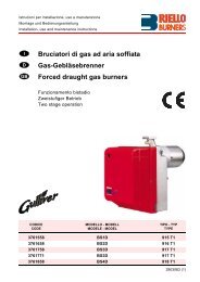
<strong>Bruciatori</strong> <strong>di</strong> <strong>gas</strong> <strong>ad</strong> <strong>aria</strong> <strong>soffiata</strong><br />
Gebläse - Gasbrenner<br />
Blown type <strong>gas</strong> burners<br />
Brûleurs gaz à air soufflé<br />
Funzionamento bista<strong>di</strong>o progressivo o modulante<br />
Zweistufig gleitender oder modulierender Betrieb<br />
Progressive two-stage or modulating operation<br />
Fonctionnement à deux allures progressives ou modulant<br />
CODICE - CODE<br />
MODELLO - MODELL<br />
MODEL - MODELE<br />
TIPO - TYP<br />
TYPE - TYPE<br />
3899700 - 3899710 RS 200/M BLU 1106 T<br />
3899701 - 3899711 RS 200/M BLU 1106 T<br />
3899730 - 3899740 RS 200/M BLU 1106 T<br />
3899731 - 3899741 RS 200/M BLU 1106 T<br />
2916448 (0) - 03/2008
3<br />
INDICE<br />
DATI TECNICI . . . . . . . . . . . . . . . . . . . . . . . . . . . . . . . . . pagina 4<br />
Versioni costruttive . . . . . . . . . . . . . . . . . . . . . . . . . . . . . . . . . . . . 4<br />
Accessori . . . . . . . . . . . . . . . . . . . . . . . . . . . . . . . . . . . . . . . . . . . 4<br />
Descrizione bruciatore . . . . . . . . . . . . . . . . . . . . . . . . . . . . . . . . . 8<br />
Imballo - Peso . . . . . . . . . . . . . . . . . . . . . . . . . . . . . . . . . . . . . . . 8<br />
Ingombro . . . . . . . . . . . . . . . . . . . . . . . . . . . . . . . . . . . . . . . . . . . 8<br />
Corredo . . . . . . . . . . . . . . . . . . . . . . . . . . . . . . . . . . . . . . . . . . . . 8<br />
Campo <strong>di</strong> lavoro . . . . . . . . . . . . . . . . . . . . . . . . . . . . . . . . . . . . . 10<br />
Caldaia <strong>di</strong> prova . . . . . . . . . . . . . . . . . . . . . . . . . . . . . . . . . . . . . 10<br />
Caldaie commerciali . . . . . . . . . . . . . . . . . . . . . . . . . . . . . . . . . . 10<br />
Pressione <strong>gas</strong>. . . . . . . . . . . . . . . . . . . . . . . . . . . . . . . . . . . . . . . 12<br />
INSTALLAZIONE. . . . . . . . . . . . . . . . . . . . . . . . . . . . . . . . . . . . 14<br />
Piastra caldaia . . . . . . . . . . . . . . . . . . . . . . . . . . . . . . . . . . . . . . 14<br />
Lunghezza boccaglio . . . . . . . . . . . . . . . . . . . . . . . . . . . . . . . . . 14<br />
Fissaggio del bruciatore alla caldaia . . . . . . . . . . . . . . . . . . . . . 14<br />
Regolazione testa <strong>di</strong> combustione . . . . . . . . . . . . . . . . . . . . . . . 16<br />
Linea alimentazione <strong>gas</strong>. . . . . . . . . . . . . . . . . . . . . . . . . . . . . . . 18<br />
Regolazioni prima dell’accensione . . . . . . . . . . . . . . . . . . . . . . . 20<br />
Servomotore. . . . . . . . . . . . . . . . . . . . . . . . . . . . . . . . . . . . . . . . 20<br />
Avviamento bruciatore . . . . . . . . . . . . . . . . . . . . . . . . . . . . . . . . 20<br />
Accensione bruciatore . . . . . . . . . . . . . . . . . . . . . . . . . . . . . . . . 20<br />
Regolazione bruciatore: . . . . . . . . . . . . . . . . . . . . . . . . . . . . . . . 22<br />
1 - Potenza all’accensione . . . . . . . . . . . . . . . . . . . . . . . . . . . . . 22<br />
2 - Potenza MAX . . . . . . . . . . . . . . . . . . . . . . . . . . . . . . . . . . . . 22<br />
3 - Potenza MIN . . . . . . . . . . . . . . . . . . . . . . . . . . . . . . . . . . . . . 24<br />
4 - Potenze interme<strong>di</strong>e . . . . . . . . . . . . . . . . . . . . . . . . . . . . . . . . 24<br />
5 - Pressostato <strong>aria</strong> . . . . . . . . . . . . . . . . . . . . . . . . . . . . . . . . . . 26<br />
6 - Pressostato <strong>gas</strong> <strong>di</strong> massima . . . . . . . . . . . . . . . . . . . . . . . . . 26<br />
7 - Pressostato <strong>gas</strong> <strong>di</strong> minima . . . . . . . . . . . . . . . . . . . . . . . . . . 26<br />
Controllo presenza fiamma . . . . . . . . . . . . . . . . . . . . . . . . . . . . 26<br />
Funzionamento bruciatore . . . . . . . . . . . . . . . . . . . . . . . . . . . . . 28<br />
Controlli finali . . . . . . . . . . . . . . . . . . . . . . . . . . . . . . . . . . . . . . . 30<br />
Manutenzione. . . . . . . . . . . . . . . . . . . . . . . . . . . . . . . . . . . . . . . 30<br />
Anomalie - Rime<strong>di</strong> . . . . . . . . . . . . . . . . . . . . . . . . . . . . . . . . . . . 32<br />
Normale funzionamento / Tempo <strong>di</strong> rilevazione fiamma. . . . . . . 36<br />
Appen<strong>di</strong>ce. . . . . . . . . . . . . . . . . . . . . . . . . . . . . . . . . . . . . . . . . 38<br />
Collegamenti elettrici . . . . . . . . . . . . . . . . . . . . . . . . . . . . . . . . . 38<br />
Schema qu<strong>ad</strong>ro elettrico . . . . . . . . . . . . . . . . . . . . . . . . . . . . . . 38<br />
Avvertenza<br />
Le figure richiamate nel testo sono così in<strong>di</strong>cate:<br />
1)(A)<br />
= Particolare 1 della figura A nella stessa pagina del testo;<br />
1)(A)p.8 = Particolare 1 della figura A riportata a pagina 8.<br />
I<br />
INHALT<br />
TECHNISCHE ANGABEN . . . . . . . . . . . . . . . . . . . . . . . . . Seite 5<br />
Bauv<strong>aria</strong>nten . . . . . . . . . . . . . . . . . . . . . . . . . . . . . . . . . . . . . . . . . 5<br />
Zubehör. . . . . . . . . . . . . . . . . . . . . . . . . . . . . . . . . . . . . . . . . . . . . 5<br />
Brennerbeschreibung . . . . . . . . . . . . . . . . . . . . . . . . . . . . . . . . . . 9<br />
Verpackung - Gewicht . . . . . . . . . . . . . . . . . . . . . . . . . . . . . . . . . . 9<br />
Abmessungen . . . . . . . . . . . . . . . . . . . . . . . . . . . . . . . . . . . . . . . . 9<br />
Ausstattung . . . . . . . . . . . . . . . . . . . . . . . . . . . . . . . . . . . . . . . . . . 9<br />
Regelbereich . . . . . . . . . . . . . . . . . . . . . . . . . . . . . . . . . . . . . . . . 11<br />
Prüfkessel . . . . . . . . . . . . . . . . . . . . . . . . . . . . . . . . . . . . . . . . . . 11<br />
Handelsübliche Kessel . . . . . . . . . . . . . . . . . . . . . . . . . . . . . . . . 11<br />
Gasdruck. . . . . . . . . . . . . . . . . . . . . . . . . . . . . . . . . . . . . . . . . . . 13<br />
INSTALLATION . . . . . . . . . . . . . . . . . . . . . . . . . . . . . . . . . . . . . 15<br />
Kesselplatte. . . . . . . . . . . . . . . . . . . . . . . . . . . . . . . . . . . . . . . . . 15<br />
Flammrohrlänge . . . . . . . . . . . . . . . . . . . . . . . . . . . . . . . . . . . . . 15<br />
Befestigung des Brenners am Heizkessel . . . . . . . . . . . . . . . . . 15<br />
Einstellung des Flammkopfs . . . . . . . . . . . . . . . . . . . . . . . . . . . . 17<br />
Gaszuleitung . . . . . . . . . . . . . . . . . . . . . . . . . . . . . . . . . . . . . . . . 19<br />
Einstellungen vor der Zündung . . . . . . . . . . . . . . . . . . . . . . . . . . 21<br />
Stellantrieb . . . . . . . . . . . . . . . . . . . . . . . . . . . . . . . . . . . . . . . . . 21<br />
Anfahren des Brenners . . . . . . . . . . . . . . . . . . . . . . . . . . . . . . . . 21<br />
Zündung des Brenners . . . . . . . . . . . . . . . . . . . . . . . . . . . . . . . . 21<br />
Brennereinstellung: . . . . . . . . . . . . . . . . . . . . . . . . . . . . . . . . . . . 23<br />
1 - Zündleistung . . . . . . . . . . . . . . . . . . . . . . . . . . . . . . . . . . . . . 23<br />
2 - Höchstleistung . . . . . . . . . . . . . . . . . . . . . . . . . . . . . . . . . . . . 23<br />
3 - Mindestleistung . . . . . . . . . . . . . . . . . . . . . . . . . . . . . . . . . . . 25<br />
4 - Zwischenleistungen . . . . . . . . . . . . . . . . . . . . . . . . . . . . . . . . 25<br />
5 - Luft-Druckwächter . . . . . . . . . . . . . . . . . . . . . . . . . . . . . . . . . 27<br />
6 - Gas-Höchstdruckwächter. . . . . . . . . . . . . . . . . . . . . . . . . . . . 27<br />
7 - Gas-Mindestdruckwächter . . . . . . . . . . . . . . . . . . . . . . . . . . . 27<br />
Flammenüberwachung . . . . . . . . . . . . . . . . . . . . . . . . . . . . . . . . 27<br />
Brennerbetrieb . . . . . . . . . . . . . . . . . . . . . . . . . . . . . . . . . . . . . . 29<br />
Endkontrollen . . . . . . . . . . . . . . . . . . . . . . . . . . . . . . . . . . . . . . . 30<br />
Wartung. . . . . . . . . . . . . . . . . . . . . . . . . . . . . . . . . . . . . . . . . . . . 30<br />
Störungen - Abhilfen . . . . . . . . . . . . . . . . . . . . . . . . . . . . . . . . . . 33<br />
Normalbetrieb / Flammenfühlzeit . . . . . . . . . . . . . . . . . . . . . . . . 36<br />
Anhang. . . . . . . . . . . . . . . . . . . . . . . . . . . . . . . . . . . . . . . . . . . . 38<br />
Elektroanschlüsse . . . . . . . . . . . . . . . . . . . . . . . . . . . . . . . . . . . . 38<br />
Schaltplan . . . . . . . . . . . . . . . . . . . . . . . . . . . . . . . . . . . . . . . . . . 38<br />
Anmerkung<br />
Die Zeichnungen, auf <strong>di</strong>e im Text Bezug genommen wird, werden<br />
folgendermaßen bezeichnet:<br />
1)(A)<br />
=Detail 1 der Zeichnung A auf der gleichen Textseite;<br />
1)(A)p.8 =Detail 1 der Zeichnung A auf Seite 8.<br />
D<br />
CONTENTS<br />
TECHNICAL DATA . . . . . . . . . . . . . . . . . . . . . . . . . . . . . . .page 6<br />
V<strong>aria</strong>nts . . . . . . . . . . . . . . . . . . . . . . . . . . . . . . . . . . . . . . . . . . . . 6<br />
Accessories . . . . . . . . . . . . . . . . . . . . . . . . . . . . . . . . . . . . . . . . . 6<br />
Burner description . . . . . . . . . . . . . . . . . . . . . . . . . . . . . . . . . . . . 9<br />
Packaging - Weight . . . . . . . . . . . . . . . . . . . . . . . . . . . . . . . . . . . 9<br />
Max. <strong>di</strong>mensions . . . . . . . . . . . . . . . . . . . . . . . . . . . . . . . . . . . . . 9<br />
Standard equipment . . . . . . . . . . . . . . . . . . . . . . . . . . . . . . . . . . . 9<br />
Firing rate . . . . . . . . . . . . . . . . . . . . . . . . . . . . . . . . . . . . . . . . . . .11<br />
Test boiler. . . . . . . . . . . . . . . . . . . . . . . . . . . . . . . . . . . . . . . . . . .11<br />
Commercial boilers. . . . . . . . . . . . . . . . . . . . . . . . . . . . . . . . . . . .11<br />
Gas pressure . . . . . . . . . . . . . . . . . . . . . . . . . . . . . . . . . . . . . . . 13<br />
INSTALLATION . . . . . . . . . . . . . . . . . . . . . . . . . . . . . . . . . . . . . 15<br />
Boiler plate . . . . . . . . . . . . . . . . . . . . . . . . . . . . . . . . . . . . . . . . . 15<br />
Blast tube length . . . . . . . . . . . . . . . . . . . . . . . . . . . . . . . . . . . . 15<br />
Securing the burner to the boiler . . . . . . . . . . . . . . . . . . . . . . . . 15<br />
Combustion he<strong>ad</strong> setting . . . . . . . . . . . . . . . . . . . . . . . . . . . . . . 17<br />
Gas line . . . . . . . . . . . . . . . . . . . . . . . . . . . . . . . . . . . . . . . . . . . 19<br />
Adjustments before firing . . . . . . . . . . . . . . . . . . . . . . . . . . . . . . 21<br />
Servomotor. . . . . . . . . . . . . . . . . . . . . . . . . . . . . . . . . . . . . . . . . 21<br />
Burner starting . . . . . . . . . . . . . . . . . . . . . . . . . . . . . . . . . . . . . . 21<br />
Burner firing . . . . . . . . . . . . . . . . . . . . . . . . . . . . . . . . . . . . . . . . 21<br />
Burner calibration: . . . . . . . . . . . . . . . . . . . . . . . . . . . . . . . . . . . 23<br />
1 - Firing output . . . . . . . . . . . . . . . . . . . . . . . . . . . . . . . . . . . . . 23<br />
2 - MAX output . . . . . . . . . . . . . . . . . . . . . . . . . . . . . . . . . . . . . . 23<br />
3 - MIN output. . . . . . . . . . . . . . . . . . . . . . . . . . . . . . . . . . . . . . . 25<br />
4 - Interme<strong>di</strong>ates outputs . . . . . . . . . . . . . . . . . . . . . . . . . . . . . . 25<br />
5 - Air pressure switch . . . . . . . . . . . . . . . . . . . . . . . . . . . . . . . . 27<br />
6 - Maximum <strong>gas</strong> pressure switch . . . . . . . . . . . . . . . . . . . . . . . 27<br />
7 - Minimum <strong>gas</strong> pressure switch. . . . . . . . . . . . . . . . . . . . . . . . 27<br />
Flame present check . . . . . . . . . . . . . . . . . . . . . . . . . . . . . . . . . 27<br />
Burner operation. . . . . . . . . . . . . . . . . . . . . . . . . . . . . . . . . . . . . 29<br />
Final checks . . . . . . . . . . . . . . . . . . . . . . . . . . . . . . . . . . . . . . . . 31<br />
Maintenance. . . . . . . . . . . . . . . . . . . . . . . . . . . . . . . . . . . . . . . . 31<br />
Faults - Suggested reme<strong>di</strong>es . . . . . . . . . . . . . . . . . . . . . . . . . . . 34<br />
Normal operation / Flame sensor timing . . . . . . . . . . . . . . . . . . 37<br />
Appen<strong>di</strong>x. . . . . . . . . . . . . . . . . . . . . . . . . . . . . . . . . . . . . . . . . . 38<br />
Electrical connections. . . . . . . . . . . . . . . . . . . . . . . . . . . . . . . . . 38<br />
Layout of electric panel board . . . . . . . . . . . . . . . . . . . . . . . . . . 38<br />
N.B.<br />
Figures mentioned in the text are identified as follows:<br />
1)(A)<br />
= part 1 of figure A, same page as text;<br />
1)(A)p.8 = part 1 of figure A, page number 8.<br />
GB<br />
INDEX<br />
DONNÉES TECHNIQUES . . . . . . . . . . . . . . . . . . . . . . . . . page 7<br />
Modèles <strong>di</strong>sponibles . . . . . . . . . . . . . . . . . . . . . . . . . . . . . . . . . . . 7<br />
Accesoires. . . . . . . . . . . . . . . . . . . . . . . . . . . . . . . . . . . . . . . . . . . 7<br />
Description brûleur . . . . . . . . . . . . . . . . . . . . . . . . . . . . . . . . . . . . 9<br />
Emballage - Poids . . . . . . . . . . . . . . . . . . . . . . . . . . . . . . . . . . . . . 9<br />
Encombrement . . . . . . . . . . . . . . . . . . . . . . . . . . . . . . . . . . . . . . . 9<br />
Equipement standard . . . . . . . . . . . . . . . . . . . . . . . . . . . . . . . . . . 9<br />
Plage de puissance. . . . . . . . . . . . . . . . . . . . . . . . . . . . . . . . . . . 11<br />
Chau<strong>di</strong>ère d’essai . . . . . . . . . . . . . . . . . . . . . . . . . . . . . . . . . . . . 11<br />
Chau<strong>di</strong>ères commerciales. . . . . . . . . . . . . . . . . . . . . . . . . . . . . . 11<br />
Pression du gaz . . . . . . . . . . . . . . . . . . . . . . . . . . . . . . . . . . . . . 13<br />
INSTALLATION . . . . . . . . . . . . . . . . . . . . . . . . . . . . . . . . . . . . . 15<br />
Plaque chau<strong>di</strong>ère . . . . . . . . . . . . . . . . . . . . . . . . . . . . . . . . . . . . 15<br />
Longueur buse . . . . . . . . . . . . . . . . . . . . . . . . . . . . . . . . . . . . . . 15<br />
Fixation du brûleur à la chau<strong>di</strong>ère. . . . . . . . . . . . . . . . . . . . . . . . 15<br />
Réglage tête de combustion . . . . . . . . . . . . . . . . . . . . . . . . . . . . 17<br />
Ligne alimentation gaz . . . . . . . . . . . . . . . . . . . . . . . . . . . . . . . . 19<br />
Réglages avant l’allumage . . . . . . . . . . . . . . . . . . . . . . . . . . . . . 21<br />
Servomoteur . . . . . . . . . . . . . . . . . . . . . . . . . . . . . . . . . . . . . . . . 21<br />
Démarrage brûleur . . . . . . . . . . . . . . . . . . . . . . . . . . . . . . . . . . . 21<br />
Allumage brûleur . . . . . . . . . . . . . . . . . . . . . . . . . . . . . . . . . . . . . 21<br />
Réglage brûleur: . . . . . . . . . . . . . . . . . . . . . . . . . . . . . . . . . . . . . 23<br />
1 - Puissance à l’allumage . . . . . . . . . . . . . . . . . . . . . . . . . . . . . 23<br />
2 - Puissance maximum . . . . . . . . . . . . . . . . . . . . . . . . . . . . . . . 23<br />
3 - Puissance minimum. . . . . . . . . . . . . . . . . . . . . . . . . . . . . . . . 25<br />
4 - Puissances intermé<strong>di</strong>ares . . . . . . . . . . . . . . . . . . . . . . . . . . . 25<br />
5 - Pressostat de l’air . . . . . . . . . . . . . . . . . . . . . . . . . . . . . . . . . 27<br />
6 - Pressostat gaz seuil maximum . . . . . . . . . . . . . . . . . . . . . . . 27<br />
7 - Pressostat gaz seuil minimum . . . . . . . . . . . . . . . . . . . . . . . . 27<br />
Contrôle présence flamme . . . . . . . . . . . . . . . . . . . . . . . . . . . . . 27<br />
Fonctionnement brûleur . . . . . . . . . . . . . . . . . . . . . . . . . . . . . . . 29<br />
Contrôles finaux . . . . . . . . . . . . . . . . . . . . . . . . . . . . . . . . . . . . . 31<br />
Entretien . . . . . . . . . . . . . . . . . . . . . . . . . . . . . . . . . . . . . . . . . . . 31<br />
Anomalies/ Solutions. . . . . . . . . . . . . . . . . . . . . . . . . . . . . . . . . . 35<br />
Fonctionnement normal/ Temps de révélation flamme . . . . . . . . 37<br />
Annexe . . . . . . . . . . . . . . . . . . . . . . . . . . . . . . . . . . . . . . . . . . . . 38<br />
Branchements électriques. . . . . . . . . . . . . . . . . . . . . . . . . . . . . . 38<br />
Schéma tableau électrique . . . . . . . . . . . . . . . . . . . . . . . . . . . . . 38<br />
Attention<br />
Les figures rappelées dans le texte sont ainsi in<strong>di</strong>quées:<br />
1)(A)<br />
=Détail 1 de la figure A dans la même page du texte;<br />
1)(A)p.8 =Détail 1 de la figure A page 8.<br />
F
DATI TECNICI<br />
I<br />
9,54<br />
MODELLO<br />
RS 200/M BLU<br />
TIPO<br />
1106 T<br />
POTENZA (1) MAX. kW 1375 - 2400<br />
Mcal/h 1183 - 2064<br />
MIN. kW 570<br />
Mcal/h<br />
490<br />
COMBUSTIBILE<br />
GAS NATURALE: G20 (METANO) - G21 - G22 - G23 - G25 - G31 (GPL)<br />
G20 G25 G31<br />
- potere calorifico inferiore kWh/Sm 3<br />
8,13 24,0<br />
Mcal/Sm 3 8,3 7,0 20,86<br />
- densità assoluta kg/Sm 3 0,71 0,78 1,87<br />
- portata massima Sm 3 /h 252 295,2 99,5<br />
- pressione alla portata massima (2) mbar 28 35,6 19,6<br />
FUNZIONAMENTO<br />
• Intermittente (min. 1 arresto in 24 ore).<br />
• Due sta<strong>di</strong> progressivi o modulante con kit (ve<strong>di</strong> ACCESSORI).<br />
IMPIEGO STANDARD<br />
Caldaie: <strong>ad</strong> acqua, a vapore, <strong>ad</strong> olio <strong>di</strong>atermico<br />
TEMPERATURA AMBIENTE °C 0 - 40<br />
TEMPERATURA ARIA COMBURENTE °C max 60<br />
ALIMENTAZIONE ELETTRICA<br />
V<br />
Hz<br />
3 ~ 400/230V - 1 ~ 230V +/-10%<br />
50 Hz<br />
MOTORE ELETTRICO<br />
rpm<br />
W<br />
V<br />
2935<br />
5500<br />
230/400<br />
Corrente <strong>di</strong> funzionamento A 21,3 - 12,3<br />
Corrente <strong>di</strong> spunto A 143 - 83<br />
APPARECCHIATURA ELETTRICA<br />
RMG/M<br />
TRASFORMATORE D’ACCENSIONE<br />
V1 - V2<br />
I1 - I2<br />
230 V - 1 x 5 kV<br />
1 A - 20 mA<br />
POTENZA ELETTRICA ASSORBITA W max 6500<br />
GRADO DI PROTEZIONE IP 44<br />
CONFORMITÀ DIRETTIVE CEE 90/396 - 89/336 - 2004/108 - 73/23 - 2006/95<br />
RUMOROSITÀ (3) dBA 83,0<br />
OMOLOGAZIONE CE in progress<br />
(1) Con<strong>di</strong>zioni <strong>di</strong> riferimento: Temperatura ambiente 20°C - Temperatura <strong>gas</strong> 15°C - Pressione barometrica 1013 mbar - Altitu<strong>di</strong>ne 0 m s.l.m.<br />
(2) Pressione alla presa 17)(A)p.8 con pressione zero in camera <strong>di</strong> combustione, con la ghiera del <strong>gas</strong> 2)(B)p.12 aperta ed alla potenza massima<br />
del bruciatore<br />
(3) Pressione sonora misurata nel laboratorio combustione del costruttore, con bruciatore funzionante su caldaia <strong>di</strong> prova, alla potenza massima.<br />
VERSIONI COSTRUTTIVE PAESE CATEGORIA<br />
Bruciatore<br />
Alimentazione<br />
elettrica<br />
• KIT PER FUNZIONAMENTO MODULANTE<br />
Lunghezza<br />
boccaglio<br />
AT - CH - DK - FI - GR - IS - IT - NO - SE<br />
ES - GB - IE - PT<br />
• KIT TESTA LUNGA: cod. 3010474.<br />
• KIT POTENZIOMETRO PER INDICAZIONE POSIZIONE DI CARICO: cod. 3010416.<br />
• RAMPE GAS SECONDO NORMA EN 676 (complete <strong>di</strong> valvole, regolatore <strong>di</strong> pressione e filtro): vedere a pagina 18.<br />
.<br />
II 2H3B/P<br />
II 2H3P<br />
3899700 - 3899710 400V 373 NL II 2L3B/P<br />
3899701 - 3899711 400V 503 FR II 2Er3P<br />
3899730 - 3899740 230V 373 DE II 2ELL3B/P<br />
3899731 - 3899741 230V 503 BE I 2E(R)B , I 3P<br />
LU<br />
II 2E3B/P<br />
ACCESSORI (su richiesta):<br />
• KIT PER FUNZIONAMENTO A GPL<br />
Bruciatore<br />
RS 200/M BLU<br />
POTENZA kW 630 ÷ 2400<br />
CODICE 3010491<br />
Kit regolatore <strong>di</strong> potenza RWF40<br />
Kit regolatore <strong>di</strong> potenza con segnale<br />
4-20 mA, 0-10V<br />
I componenti da or<strong>di</strong>nare sono due:<br />
• il Regolatore <strong>di</strong> potenza da installare sul bruciatore;<br />
• la Sonda da installare sul generatore <strong>di</strong> calore<br />
I componenti da or<strong>di</strong>nare sono due:<br />
• il Convertitore <strong>di</strong> segnale analogico;<br />
• il Potenziometro<br />
Parametro da controllare<br />
Sonda<br />
Regolatore <strong>di</strong><br />
Convertitore <strong>di</strong><br />
Potenziometro<br />
potenza<br />
segnale analogico<br />
Campo <strong>di</strong> regolazione Tipo Co<strong>di</strong>ce Tipo Co<strong>di</strong>ce Tipo Co<strong>di</strong>ce Tipo Co<strong>di</strong>ce<br />
Temperatura - 100...+500°C PT 100 3010110<br />
Pressione<br />
0...2,5 bar Sonda con uscita 3010213 RWF40 3010414 ASZ... 3010416 E5202 3010415<br />
0...16 bar<br />
4...20 mA 3010214<br />
4
TECHNISCHE ANGABEN<br />
D<br />
9,54<br />
MODELL<br />
RS 200/M BLU<br />
TYP<br />
1106 T<br />
LEISTUNG (1) MAX. kW 1375 - 2400<br />
Mcal/h 1183 - 2064<br />
MIN. kW 570<br />
Mcal/h<br />
490<br />
BRENNSTOFF<br />
ERDGAS: G20 (METHAN) - G21 - G22 - G23 - G25 - G31 (FLÜSSIGGAS)<br />
G20 G25 G31<br />
- Unterer Heizwert Hu kWh/Sm 3<br />
8,13 24,0<br />
Mcal/Sm 3 8,3 7,0 20,86<br />
- Rein<strong>di</strong>chte kg/Sm 3 0,71 0,78 1,87<br />
- Höchstdurchsatz Sm 3 /h 252 295,2 99,5<br />
- Druck bei Höchstdurchsatz (2) mbar 28 35,6 19,6<br />
BETRIEB<br />
• Aussetzend (min. 1 Halt in 24 Std).<br />
• Gleitend zweistufig (modulierend mit Kit).<br />
STANDARDEINSATZ<br />
Heizkessel: mit Wasser, Dampf, <strong>di</strong>athermischem Öl<br />
RAUMTEMPERATUR °C 0 - 40<br />
TEMPERATUR VERBRENNUNGSLUFT °C max 60<br />
ELEKTRISCHE SPEISUNG<br />
V<br />
Hz<br />
3 ~ 400/230V - 1 ~ 230V +/-10%<br />
50 Hz<br />
ELEKTROMOTOR<br />
rpm<br />
W<br />
V<br />
2935<br />
5500<br />
230/400<br />
Betriebsstrom A 21,3 - 12,3<br />
Anlaßstrom A 143 - 83<br />
STEUERGERÄT<br />
RMG/M<br />
ZÜNDTRANSFORMATOR<br />
V1 - V2<br />
I1 - I2<br />
230 V - 1 x 5 kV<br />
1 A - 20 mA<br />
ELEKTRISCHE LEISTUNGSAUFNAHME W max 6500<br />
SCHUTZART IP 44<br />
CE-NORMGERECHT 90/396 - 89/336 - 2004/108 - 73/23 - 2006/95<br />
SCHALLDRUCKPEGEL (3) dBA 83,0<br />
OMOLOGAZIONE CE in progress<br />
(1) Bezugsbe<strong>di</strong>ngungen: Raumtemperatur 20°C - Gastemperatur 15°C - Barometrischer Druck 1013 mbar - Höhe 0 m ü.d.M.<br />
(2) Druck am Anschluß 17)(A)S.8 bei druckloser Brennkammer, geöffneter Gasscheibe 2)(B)S.12 und bei Höchstleistung des Brenners<br />
(3) Schalldruck, im Brennprüflabor des Herstellers mit Brenner auf Prüfkessel bei Höchstleistung.<br />
BAUVARIANTEN LAND KATEGORIE<br />
Brenner<br />
Elektrische<br />
Speisung<br />
3899700 - 3899710 400V 373 NL II 2L3B/P<br />
3899701 - 3899711 400V 503 FR II 2Er3P<br />
3899730 - 3899740 230V 373 DE II 2ELL3B/P<br />
3899731 - 3899741 230V 503 BE I 2E(R)B , I 3P<br />
LU<br />
II 2E3B/P<br />
ZUBEHÖR (auf Wunsch):<br />
• KIT FÜR FLÜSSIGGAS-BETRIEB.<br />
• KIT FÜR MODULIERENDEN BETRIEB<br />
Flammrohr<br />
Länge<br />
BRENNER<br />
RS 200/M BLU<br />
LEISTUNG kW 630 ÷ 2400<br />
CODE 3010491<br />
Leistungsregler Kit RWF40<br />
Zwei Komponenten sind zu bestellen:<br />
• der am Brenner zu installierende Leistungsregler;<br />
• der am Wärmegenerator zu installierende Fühler<br />
AT - CH - DK - FI - GR - IS - IT - NO - SE<br />
ES - GB - IE - PT<br />
• KIT LANGER KOPF: Code 3010474.<br />
• KIT POTENTIOMETER ZUR ANZEIGE DER FÜLLPOSITION: Code 3010416.<br />
• GASARMATUREN GEMÄß NORM EN 676 (mit Ventilen, Druckregler und Filter): siehe Seite 18.<br />
.<br />
II 2H3B/P<br />
II 2H3P<br />
Leistungsregler Kit mit Signal<br />
4-20 mA, 0-10V<br />
Zwei Komponenten sind zu bestellen:<br />
• der analogischer Signalwandler;<br />
• das Potentiometer<br />
analogischer<br />
Zu prüfender Parameter Fühler Leistungsregler Potentiometer<br />
Analogsignalwandler<br />
Regelbereich Typ Code Typ Code Typ Code Typ Code<br />
Temperatur - 100...+500°C PT 100 3010110<br />
Druck<br />
0...2,5 bar<br />
0...16 bar<br />
Fühler mit<br />
Ausgang<br />
4...20 mA<br />
3010213<br />
3010214<br />
RWF40 3010414 ASZ... 3010416 E5202 3010415<br />
5
TECHNICAL DATA<br />
GB<br />
9.54<br />
MODEL<br />
RS 200/M BLU<br />
TYP<br />
1106 T<br />
OUTPUT (1) MAX. kW 1375 - 2400<br />
Mcal/h 1183 - 2064<br />
MIN. kW 570<br />
Mcal/h<br />
490<br />
FUEL<br />
NATURAL GAS: G20 (METHANE) - G21 - G22 - G23 - G25 - G31 (LPG)<br />
G20 G25 G31<br />
- net calorific value kWh/Sm 3<br />
8.13 24.0<br />
Mcal/Sm 3 8.3 7.0 20.86<br />
- absolute density kg/Sm 3 0.71 0.78 1.87<br />
- max. delivery Sm 3 /h 252 295.2 99.5<br />
- pressure at max. delivery (2) mbar 28 35.6 19.6<br />
OPERATION<br />
• On-Off (1 stop min each 24 hours).<br />
• Progressive two-stage or modulating by kit (see ACCESSOIRES).<br />
STANDARD APPLICATIONS<br />
Boilers: water, steam, <strong>di</strong>athermic oil<br />
AMBIENT TEMPERATUR °C 0 - 40<br />
COMBUSTION AIR TEMPERATURE °C max 60<br />
ELECTRICAL SUPPLY<br />
V<br />
Hz<br />
3 ~ 400/230V - 1 ~ 230V +/-10%<br />
50 Hz<br />
ELECTRIC MOTOR<br />
rpm<br />
W<br />
V<br />
2935<br />
5500<br />
230/400<br />
Running current A 21,3 - 12,3<br />
Start-up current A 143 - 83<br />
CONTROL BOX<br />
RMG/M<br />
IGNITION TRANSFORMER<br />
V1 - V2<br />
I1 - I2<br />
230 V - 1 x 5 kV<br />
1 A - 20 mA<br />
ELECTRICAL POWER CONSUMPTION W max 6500<br />
ELECTRICAL PROTECTION IP 44<br />
IN CONFORMITY WITH EEC DIRECTIVES 90/396 - 89/336 - 2004/108 - 73/23 - 2006/95<br />
NOISE LEVELS (3) dBA 83.0<br />
APPROVAL CE in progress<br />
(1) Reference con<strong>di</strong>tions: Ambient temperature 20°C - Gas temperature 15°C - Barometric pressure 1013 mbar - Altitude 0 m s.l.m.<br />
(2) Pressure at test point 17)(A)p.8, with zero pressure in the combustion chambre, with open <strong>gas</strong> ring 2)(B)p.12 an maximum burner output<br />
(2) Sound pressure measured in manufacturer’s combustion laboratory, with burner operating on test boiler and at maximum rated output.<br />
VARIANTS COUNTRY CATEGORY<br />
Burner<br />
Electrical<br />
supply<br />
3899700 - 3899710 400V 373 NL II 2L3B/P<br />
3899701 - 3899711 400V 503 FR II 2Er3P<br />
3899730 - 3899740 230V 373 DE II 2ELL3B/P<br />
3899731 - 3899741 230V 503 BE I 2E(R)B , I 3P<br />
LU<br />
II 2E3B/P<br />
ACCESSORIES (optional):<br />
• KIT FOR LPG OPERATION<br />
• KIT FOR MODULATING OPERATION<br />
Blast tube<br />
lenght<br />
BURNER<br />
RS 200/M BLU<br />
OUTPUT kW 630 ÷ 2400<br />
CODE 3010491<br />
Output power regulator kit RWF40<br />
There are two components to order:<br />
• the Output power regulator to install on the burner;<br />
• the Probe to install on the heat generator<br />
Parameter to control<br />
Probe<br />
AT - CH - DK - FI - GR - IS - IT - NO - SE<br />
ES - GB - IE - PT<br />
Output power<br />
regulator<br />
• LONG HEAD KIT: code 3010474.<br />
• POTENTIOMETER KIT FOR THE INDICATION OF LOAD POSITION: code 3010416.<br />
• GAS TRAIN ACCORDING TO REGULATION EN 676 (with valve, pressure governor and filter): see page 18.<br />
II 2H3B/P<br />
II 2H3P<br />
Output power regulator with signal<br />
4-20 mA, 0-10V<br />
There are two components to order:<br />
• the Analogic signal converter;<br />
• the Potentiometer<br />
Potentiometer<br />
Analogic signal<br />
converter<br />
Adjustment field Type Code Type Code Type Code Type Code<br />
Temperature - 100...+500°C PT 100 3010110<br />
Pressure<br />
0...2.5 bar<br />
0...16 bar<br />
Probe with outlet<br />
4...20 mA<br />
3010213<br />
3010214<br />
RWF40 3010414 ASZ... 3010416 E5202 3010415<br />
6
DONNEES TECHNIQUES<br />
F<br />
9,54<br />
MODELE<br />
RS 200/M BLU<br />
TYPE<br />
1106 T<br />
PUISSANCE (1) MAX. kW 1375 - 2400<br />
Mcal/h 1183 - 2064<br />
MIN. kW 570<br />
Mcal/h<br />
490<br />
COMBUSTIBLE<br />
GAZ NATUREL: G20 (METHANE) - G21 - G22 - G23 - G25 - G31 (GPL)<br />
G20 G25 G31<br />
- pouvoir calorifique inférieur kWh/Sm 3<br />
8,13 24,0<br />
Mcal/Sm 3 8,3 7,0 20,86<br />
- densité absolue kg/Sm 3 0,71 0,78 1,87<br />
- pression au débit max. Sm 3 /h 252 295,2 99,5<br />
- pression au débit max. (2) mbar 28 35,6 19,6<br />
FONCTIONNEMENT<br />
• Intermittent (1 arrêt min en 24 heures).<br />
• Deux allure progressives ou modulant avec kit (voir ACCESSOIRES).<br />
EMPLOI STANDARD<br />
Chau<strong>di</strong>ères à eau, à vapeur, à huile <strong>di</strong>athermique<br />
TEMPERATURE AMBIANTE °C 0 - 40<br />
TEMPERATURE AIR COMBURANT °C max 60<br />
ALIMENTATION ELECTRIQUES<br />
V<br />
Hz<br />
3 ~ 400/230V - 1 ~ 230V +/-10%<br />
50 Hz<br />
MOTEUR ELECTRIQUE<br />
rpm<br />
W<br />
V<br />
2935<br />
5500<br />
230/400<br />
Courant de fonctionnement A 21,3 - 12,3<br />
Courant de pointe A 143 - 83<br />
COFFRET DE SÉCURITÉ<br />
RMG/M<br />
TRANSFORMATEUR D’ALLUMAGE<br />
V1 - V2<br />
I1 - I2<br />
230 V - 1 x 5 kV<br />
1 A - 20 mA<br />
PUISSANCE ELECTRIQUE ABSORBEE W max 6500<br />
DEGRE DE PROTECTION IP 44<br />
CONFORMÉMENT AUX DIRECTIVES CEE 90/396 - 89/336 - 2004/108 - 73/23 - 2006/95<br />
NIVEAU DE BRUIT (3) dBA 83,0<br />
HOMOLOGATION CE in progress<br />
(1) Con<strong>di</strong>tions de référence: Température ambiante 20°C - Température gaz 15°C - Pression barométrique 1013 mbar - Altitude 0 m au-dessus<br />
du niveau de la mer.<br />
(2) Pression à la prise 17)(A)p.8, avec une pression nulle dans la chambre de combustion, avec la bague du gaz 2)(B)p.12 ouverte et à la puissance<br />
maximum du brûleur.<br />
(3) Pression acoustique mesurée dans le laboratoire combustion du constructeur, le brûleur fonctionnant sur une chau<strong>di</strong>ère d’essai à la puissance<br />
maximum.<br />
MODELES DISPONIBLES PAYS CATEGORIE<br />
Brûleur<br />
Alimentation<br />
electriques<br />
Longuer<br />
buse<br />
3899700 - 3899710 400V 373 NL II 2L3B/P<br />
3899701 - 3899711 400V 503 FR II 2Er3P<br />
3899730 - 3899740 230V 373 DE II 2ELL3B/P<br />
3899731 - 3899741 230V 503 BE I 2E(R)B , I 3P<br />
LU<br />
II 2E3B/P<br />
ACCESSOIRES (sur demande):<br />
• KIT POUR FONCTIONNEMENT AU GPL<br />
BRULEUR<br />
RS 200/M BLU<br />
PUISSANCE kW 630 ÷ 2400<br />
CODE 3010491<br />
• KIT POUR FONCTIONNEMENT MODULANT<br />
Kit régulateur de puissance RWF40<br />
Il y a deux composants à commander:<br />
• le Régulateur de puissance à installer sur le brûleur;<br />
• la Sonde à installer sur le générateur de chaleur<br />
Paramètre à contrôler<br />
Sonde<br />
AT - CH - DK - FI - GR - IS - IT - NO - SE<br />
ES - GB - IE - PT<br />
Régulateur de<br />
puissance<br />
• KIT TETE LONGUE: code 3010474.<br />
• KIT POTENTIOMETRE POUR INDICATION POSITION DE CHARGEMENT: code 3010416.<br />
• RAMPES GAZ SELON LA NORME EN 676 (avec vannes, regulateur de pression et filtre): voir p. 18.<br />
II 2H3B/P<br />
II 2H3P<br />
Kit régulateur de puissance avec signal<br />
4-20 mA, 0-10V<br />
Il y a deux composants à commander:<br />
• le Convertisseur de signal analogique;<br />
• le Potentiomètre<br />
Potentiomètre<br />
Convertisseur de<br />
signal analogique<br />
Plage de réglage TYPE CODE TYPE CODE TYPE CODE TYPE CODE<br />
Température - 100...+500°C PT 100 3010110<br />
Pression 0...2,5 bars<br />
0...16 bars<br />
Sonde avec sortie<br />
4...20 mA<br />
3010213<br />
3010214<br />
RWF40 3010414 ASZ... 3010416 E5202 3010415<br />
7
22<br />
23 24 25 26<br />
21<br />
20<br />
9 10 29<br />
7 6 5 4 3<br />
1 2<br />
27<br />
11<br />
12<br />
13 14 28 15 16 8 17 18 19<br />
(A)<br />
mm A B C kg<br />
RS 200/M BLU 1400 780 1000 95<br />
(B)<br />
D8542<br />
D36<br />
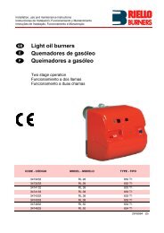
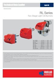
DESCRIZIONE BRUCIATORE (A)<br />
1 Testa <strong>di</strong> combustione<br />
2 Elettrodo <strong>di</strong> accensione<br />
3 Vite per regolazione testa <strong>di</strong> combustione<br />
4 Pressostato <strong>gas</strong> <strong>di</strong> massima<br />
5 Manicotto<br />
6 Servomotore, comanda la farfalla del <strong>gas</strong> e,<br />
tramite una camma a profilo v<strong>aria</strong>bile, la serranda<br />
dell’<strong>aria</strong>.<br />
Durante la sosta del bruciatore la serranda<br />
dell’<strong>aria</strong> è completamente chiusa per ridurre<br />
al minimo le <strong>di</strong>spersioni termiche della<br />
caldaia dovute al tiraggio del camino che<br />
richiama l’<strong>aria</strong> dalla bocca <strong>di</strong> aspirazione del<br />
ventilatore<br />
7 Spina-presa sul cavo della sonda <strong>di</strong> ionizzazione<br />
8 Prolunghe per guide 16)<br />
9 Contattore motore e relè termico con pulsante<br />
<strong>di</strong> sblocco<br />
10 Un interruttore per:<br />
funzionamento automatico-manuale-spento<br />
Un pulsante per:<br />
aumento - <strong>di</strong>minuzione potenza<br />
11 Morsettiera<br />
12 Passacavi per i collegamenti elettrici a cura<br />
dell’installatore<br />
13 Apparecchiatura elettrica con avvisatore<br />
luminoso <strong>di</strong> blocco e pulsante <strong>di</strong> sblocco<br />
14 Visore fiamma<br />
15 Pressostato <strong>aria</strong> <strong>di</strong> minima<br />
(tipo <strong>di</strong>fferenziale)<br />
16 Guide per apertura bruciatore ed ispezione<br />
alla testa <strong>di</strong> combustione<br />
17 Presa <strong>di</strong> pressione <strong>gas</strong> e vite fissa testa<br />
18 Presa <strong>di</strong> pressione <strong>aria</strong><br />
19 Sonda per il controllo presenza fiamma<br />
20 Serranda <strong>aria</strong><br />
21 Ingresso <strong>aria</strong> nel ventilatore<br />
22 Viti per il fissaggio ventilatore al manicotto<br />
23 Condotto arrivo <strong>gas</strong><br />
24 Valvola farfalla <strong>gas</strong><br />
25 Flangia per il fissaggio alla caldaia<br />
26 Disco <strong>di</strong> stabilità fiamma<br />
27 Staffa per l’applicazione del kit per funzionamento<br />
modulante<br />
28 Relè contatti puliti<br />
29 Spina per il collegamento del kit per funzionamento<br />
modulante<br />
Vi sono due possibilità <strong>di</strong> blocco del bruciatore:<br />
Blocco apparecchiatura: l’accensione del pulsante<br />
dell’apparecchiatura 13)(A) avverte che il<br />
bruciatore è in blocco.<br />
Per sbloccare premere il pulsante.<br />
Blocco motore: per sbloccare premere il pulsante<br />
del relè termico 9)(A).<br />
IMBALLO - PESO (B) - misure in<strong>di</strong>cative<br />
• L’ imballo del bruciatore appoggia su una<br />
pedana in legno particolarmente <strong>ad</strong>atta ai carrelli<br />
elevatori. Le <strong>di</strong>mensioni <strong>di</strong> ingombro<br />
dell'imballo sono riportate nella tabella (B).<br />
• Il peso del bruciatore completo <strong>di</strong> imballo è<br />
in<strong>di</strong>cato nella tabella (B).<br />
(C)<br />
(1) Boccaglio: corto-lungo / Flammenrohr: kurz-lang<br />
Blast tube: short-long / Buse: courte-longue<br />
D1702<br />
mm A B C D E F (1) G H I (1) L M N O<br />
RS 200/M BLU 732 427 305 555 872 373-503 222 430 1442-1587 230 141 260 Rp2<br />
INGOMBRO (C) - misure in<strong>di</strong>cative<br />
L'ingombro del bruciatore è riportato in fig. (C).<br />
Tener presente che per ispezionare la testa <strong>di</strong><br />
combustione il bruciatore deve essere aperto<br />
arretrandone la parte posteriore sulle guide.<br />
L'ingombro del bruciatore aperto è in<strong>di</strong>cato dalla<br />
quota I.<br />
CORREDO<br />
1 - Flangia per rampa <strong>gas</strong><br />
1 - Guarnizione per flangia<br />
4 - Viti per fissare la flangia M 10 x 40 al<br />
regolatore a farfalla <strong>gas</strong><br />
4 - Viti per fissaggio manicotto flangia del bruciatore<br />
alla caldaia: M 16 x 40<br />
1 - Schermo termico<br />
2 - Prolunghe per guide 16)(A) (modelli con<br />
boccaglio 1587 mm)<br />
2 - Pressacavo<br />
1 - Istruzione<br />
1 - Catalogo ricambi<br />
8
BRENNERBESCHREIBUNG (A)<br />
1 Flammkopf<br />
2 Zündelektrode<br />
3 Einstellschraube des Flammkopfes<br />
4 Gas-Höchstdruckwächter<br />
5 Gasanschluß-Muffe<br />
6 Stellantrieb zur Steuerung der Gasdrossel<br />
und, über einen Nocken mit v<strong>aria</strong>blem Profil,<br />
der Luftklappe.<br />
Bei Brennerstillstand ist <strong>di</strong>e Luftklappe<br />
geschlossen, um <strong>di</strong>e Wärmeverluste des<br />
Kessels durch den Kaminzug mit Luftnachführung<br />
von der Saugöffnung des Gebläses<br />
zu vermeiden<br />
7 Steckanschluß am Kabel der Ionisationssonde<br />
8 Verlängerungen zu Gleitschienen 16)<br />
9 Motorschütz und Überstromauslöser mit<br />
Entriegelungsschalter<br />
10 Ein Schalter für:<br />
Automatischer Betrieb-Manueller Betrieb-Aus<br />
Ein Druckknopf für:<br />
Leistungserhöhung - Leistungabminderung<br />
11 Klemmenbrett<br />
12 Kabeldurchgänge für <strong>di</strong>e Elektroanschlüsse<br />
vom Installateur<br />
13 Steuergerät mit Kontrollampe für Störabschaltung<br />
und Entriegelungsschalter<br />
14 Flammen-Sichtfenster<br />
15 Mindestluftdruckwächter<br />
(Differentialtyp)<br />
16 Gleitschienen zur Öffnung des Brenners und<br />
für <strong>di</strong>e Kontrolle des Flammkopfs<br />
17 Gasdruckentnahmestelle und Befestigungsschraube<br />
des Flammkopfes<br />
18 Luftdruckentnahmestelle<br />
19 Flammenfühler<br />
20 Luftklappe<br />
21 Lufteinlaß zum Gebläse<br />
22 Befestigungsschraube des Gebläses an der<br />
Gasanschluß-Muffe<br />
23 Gaszuleitung<br />
24 Gasdrossel<br />
25 Befestigungsflansch am Kessel<br />
26 Stauscheibe<br />
27 Tragbügel zum Einbau des Kits für modulierenden<br />
Betrieb<br />
28 Relais mit sauberen Kontakten<br />
29 Stecker zum Anschluss des Kits für modulierenden<br />
Betrieb<br />
Die Störabschaltungen des Brenners können<br />
zweierlei Art sein:<br />
Störabschaltung des Gerätes: Das Aufleuchten<br />
des Druckknopfes des Gerätes 13)(A) weist auf<br />
eine Störabschaltung des Brenners hin.<br />
Zur Entriegelung den Druckknopf drücken.<br />
Störabschaltung des Motors: Entriegelung durch<br />
Drükken auf den Druckknopf des Überstromauslösers<br />
9)(A).<br />
VERPACKUNG - GEWICHT (B) - Richtwerte<br />
• Der Brenner steht auf einem besonders<br />
für<strong>di</strong>e Handhabung mit Hubwagen geeignetem<br />
Holzrahmen. Die Außenabmessungen der Verpackung<br />
sind in Tabelle (B) aufgeführt.<br />
• Das Gesamtgewicht des Brenners einschließlich<br />
Verpackung wird aus Tabelle (B)<br />
ersichtlich (B).<br />
ABMESSUNGEN (C) - Richtwerte<br />
Die Brennerabmessungen sind in der Abb. (C)<br />
angeführt.<br />
Zur Inspektion des Flammkopfes muß der Brenner<br />
zurückgeschoben und nach oben geschwenkt<br />
werden.<br />
Die Abmessungen des offenen Brenners, ohne<br />
Verkleidung, sind unter I aufgeführt.<br />
AUSSTATTUNG<br />
1 - Flansch für Gasarmaturen<br />
1 - Dichtung für Flansch<br />
4 - Schrauben für <strong>di</strong>e Befestigung des M10 x<br />
40 Flansches an den Gasdrosselregler<br />
4 - Schrauben für <strong>di</strong>e Befestigung des Brenner-Gasanschlußflansches<br />
am Kessel:<br />
M 16 x 40<br />
1 - Wärmeschild<br />
2 - Verlängerungen zu Gleitschienen 16)(A)<br />
(Typen mit 1587 mm Flammrohr)<br />
2 - Zugentlastung<br />
1 - Anleitung<br />
1 - Ersatzteile Katalog<br />
BURNER DESCRIPTION (A)<br />
1 Combustion he<strong>ad</strong><br />
2 Ignition electrode<br />
3 Screw for combustion he<strong>ad</strong> <strong>ad</strong>justment<br />
4 Max. <strong>gas</strong> pressure switch<br />
5 Sleeve<br />
6 Servomotor controlling the <strong>gas</strong> butterfly<br />
valve and of air gate valve (by means of a<br />
v<strong>aria</strong>ble profile cam mechanism).<br />
When the burner is not operating the air gate<br />
valve is fully closed in order to reduce heat<br />
<strong>di</strong>spersion from the boiler due to the flue<br />
draught which draws air from the fan suction<br />
inlet.<br />
7 Plug-socket on ionisation proble cable<br />
8 Extensions for slide bars 16)<br />
9 Motor contactor and thermal cut-out with<br />
reset button<br />
10 Power switch for <strong>di</strong>fferent operations:<br />
automatic - manual - off<br />
Button for:<br />
Power increase - power reduction<br />
11 Terminal strip<br />
12 Fairle<strong>ad</strong>s for electrical connections by<br />
installer<br />
13 Control box with lock-out pilot light and lockout<br />
reset button<br />
14 Flame inspection window<br />
15 Minimum air pressure switch<br />
(<strong>di</strong>fferential operating type)<br />
16 Slide bars for opening the burner and<br />
inspecting the combustion he<strong>ad</strong><br />
17 Gas pressure test point and he<strong>ad</strong> fixing<br />
screw<br />
18 Air pressure test point<br />
19 Flame sensor probe<br />
20 Air gate valve<br />
21 Air inlet to fan<br />
22 Screws securing fan to sleeve<br />
23 Gas input pipework<br />
24 Gas butterfly valve<br />
25 Boiler mounting flange<br />
26 Flame stability <strong>di</strong>sk<br />
27 Bracket for mounting the modulating operation<br />
kit<br />
28 Clean contact relay<br />
29 Plug for connection of modulating operation<br />
kit<br />
Two types of burner failure may occur:<br />
Control Box Lock-out: if the control box 13)(A)<br />
pushbutton lights up, it in<strong>di</strong>cates that the burner<br />
is in lock-out.<br />
To reset, press the pushbutton.<br />
Motor trip: release by pressing the pushbutton<br />
on thermal relay 9)(A).<br />
PACKAGING - WEIGHT (B) - Approximate<br />
measurements<br />
• The burners stands on a wooden base which<br />
can be lifted by fork-lifts. Outer <strong>di</strong>mensions of<br />
packaging are in<strong>di</strong>cated in (B).<br />
• The weight of the burner complete with packaging<br />
is in<strong>di</strong>cated in Table (B).<br />
MAX. DIMENSIONS (C) - Approximate measurements<br />
The maximum <strong>di</strong>mensions of the burner are<br />
given in (C).<br />
Bear in mind that inspection of the combustion<br />
he<strong>ad</strong> requires the burner to be opened and the<br />
rear part withdrawn on the slide bars.<br />
The maximum <strong>di</strong>mension of the burner, without<br />
casing, when open is give by measurement I.<br />
STANDARD EQUIPMENT<br />
1 - Gas train flange<br />
1 - Flange <strong>gas</strong>ket<br />
4 - Flange fixing screws M 10 x 40 to the butterfly<br />
valve<br />
4 - Screws to secure the burner sleeve with<br />
flange to the boiler: M 16 x 40<br />
1 - Thermal insulation screen<br />
2 - Extensions for slide bars 16)(A)<br />
(for models with 1587 mm blast tube)<br />
2 - Cable gland<br />
1 - Instruction booklet<br />
1 - Spare parts list<br />
9<br />
DESCRIPTION BRULEUR (A)<br />
1 Tête de combustion<br />
2 Electrode d'allumage<br />
3 Vis pour réglage tête de combustion<br />
4 Pressostat gaz seuil maximum<br />
5 Manchon<br />
6 Servomoteur de commande de la vanne<br />
papillon du gaz et, par came à profil v<strong>aria</strong>ble,<br />
du volet d'air. Lors de l'arrêt du brûleur ce<br />
volet d'air est complètement fermé afin de<br />
réduire le plus possible les <strong>di</strong>spersions thermiques<br />
de la chau<strong>di</strong>ère causées par le tirage<br />
du conduit de rappel d'air sur la bouche<br />
d'aspiration du ventilateur.<br />
7 Fiche prise sur câble sonde d’ionisation<br />
8 Rallonges pour guides 16)<br />
9 Contacteur moteur et relais thermique avec<br />
bouton de déblocage<br />
10 Un interrupteur pour le fonctionnement:<br />
automatique - manuel - éteint<br />
Un bouton pour:<br />
augmentation - <strong>di</strong>minution de puissance<br />
11 Bornier<br />
12 Passe-câbles pour les connexions électriques<br />
aux soins de l’installateur<br />
13 Coffret de sécurité avec signal lumineux de<br />
blocage et bouton de déblocage<br />
14 Viseur flamme<br />
15 Pressostat air seul minimum<br />
(type <strong>di</strong>fférentiel)<br />
16 Guides pour ouverture brûleur et inspection<br />
de la tête de combustion<br />
17 Prise de pression gaz et vis de fixation tête<br />
18 Prise de pression air<br />
19 Sonde de contrôle présence flamme<br />
20 Volet d'air<br />
21 Entrée d’air dans le ventilateur<br />
22 Vis de fixation ventilateur au manchon<br />
23 Canalisation d’arrive du gaz<br />
24 Vanne papillon gaz<br />
25 Bride de fixation à la chau<strong>di</strong>ère<br />
26 Disque de stabilité de la flamme<br />
27 Support pour l’application du kit pour fonctionnement<br />
modulant<br />
28 Relais contacts propres<br />
29 Fiche pour le branchement du kit pour fonctionnement<br />
modulant<br />
Il existe deux types de blocage du brûleur:<br />
Blocage coffret: l'allumage du bouton du coffret<br />
de sécurité 13)(A) avertit que le brûleur s'est<br />
bloqué.<br />
Pour le débloquer appuyer sur le bouton.<br />
Blocage moteur: pour le débloquer appuyer sur<br />
le bouton-poussoir du relais thermique 9)(A).<br />
EMBALLAGE - POIDS (B) - Mesures in<strong>di</strong>catives<br />
• Le brûleur est placé sur une palette qui peut<br />
être soulevée par des chariots transpalettes.<br />
Les <strong>di</strong>mensions d’encombrement de l’emballage<br />
sont reportées dans le tableau (B).<br />
• Le poids du brûleur avec son emballage est<br />
in<strong>di</strong>qué dans le tab. (B).<br />
ENCOMBREMENT (C) - Mesures in<strong>di</strong>catives<br />
L'encombrement du brûleur est in<strong>di</strong>qué dans le<br />
tab. (C).<br />
Il faut tenir compte du fait que pour inspecter la<br />
tête de combustion, le brûleur doit être ouvert, la<br />
partie arrière reculée sur les guides. L'encombrement<br />
du brûleur ouvert, sans carter, est<br />
in<strong>di</strong>qué par la cote I.<br />
EQUIPEMENT STANDARD<br />
1 - Bride pour rampe gaz<br />
1 - Joint pour bride<br />
4 - Vis pour fixer la bride M 10 x 40 au régulateur<br />
à papillon gaz<br />
4 - Vis pour fixer le manchon avec bride du<br />
brûleur à la chau<strong>di</strong>ère: M 16 x 40<br />
1 - Ecran thermique<br />
2 - Rallonges de guides 16)(A) (modèles avec<br />
buse 1587 mm)<br />
2 - Passe-câble<br />
1 - Instructions<br />
1 - Catalogue pièces détachées
14<br />
CAMPO DI LAVORO (A)<br />
La potenza del bruciatore v<strong>aria</strong> in funzionamento<br />
tra:<br />
12<br />
• una POTENZA MASSIMA, scelta entro l’area A.<br />
CAM. COMB. / FEUERRAUM mbar<br />
COMB. CHAMBER / CHAMB. COMB.<br />
(A)<br />
10<br />
8<br />
6<br />
4<br />
2<br />
0<br />
-2<br />
Mcal/h<br />
kW<br />
200<br />
A<br />
300 500 700 900 1100 1300 1500 1700 1900<br />
400 600 800 1000 1200 1400 1600 1800 2000 2200<br />
2100<br />
2400<br />
D8532<br />
• e una POTENZA MINIMA, che non deve<br />
essere inferiore al limite minimo del <strong>di</strong>agramma:<br />
RS 200/M BLU = 570 kW<br />
Attenzione:<br />
Il CAMPO DI LAVORO è stato ricavato alla temperatura<br />
ambiente <strong>di</strong> 20 °C, alla pressione barometrica<br />
<strong>di</strong> 1013 mbar (circa 0 m s.l.m.) e con la<br />
testa <strong>di</strong> combustione regolata come in<strong>di</strong>cato a p.<br />
16.<br />
CALDAIA DI PROVA (B)<br />
I campi <strong>di</strong> lavoro sono stati ricavati in speciali<br />
caldaie <strong>di</strong> prova, secondo la norma EN 676.<br />
Riportiamo in (B) <strong>di</strong>ametro e lunghezza della<br />
camera <strong>di</strong> combustione <strong>di</strong> prova.<br />
Esempio: Potenza 650 Mcal/h:<br />
<strong>di</strong>ametro 60 cm - lunghezza 2 m.<br />
CAM. COMB. / FEUERRAUM m<br />
COMB. CHAMBER / CHAMB. COMB.<br />
ATTENZIONE - ACHTUNG - ATTENTION<br />
Il campo <strong>di</strong> lavoro è riferito al funzionamento con combustibile G20 - G25. In caso <strong>di</strong> utilizzo<br />
<strong>di</strong> G31, la potenza minima passa da 570 a 630 kW.<br />
Der Betriebsbereich bezieht sich auf den Betrieb mit Brennstoff G20 - G25. Bei Verwendung<br />
von G31 wechselt <strong>di</strong>e Mindestleistung von 570 zu 630 kW.<br />
The firing rate refers to the operation with fuel G20 - G25. In case G31 is used, the minimum<br />
output goes from 570 to 630 kW.<br />
La plage de puissance concerne le fonctionnement avec du combustible G20 - G25. En cas<br />
d'utilisation de G31, la puissance minimale passe de 570 à 630 kW.<br />
CALDAIE COMMERCIALI (C)<br />
Il bruciatore RS 200/M BLU è <strong>ad</strong>atto per funzionare<br />
sia su caldaie <strong>ad</strong> inversione <strong>di</strong> fiamma,<br />
sia su caldaie con camera <strong>di</strong> combustione a<br />
deflusso dal fondo (tre giri <strong>di</strong> fumo) sulle quali si<br />
ottengono i migliori risultati <strong>di</strong> basse emissioni <strong>di</strong><br />
NOx.<br />
Lo spessore massimo del portello anteriore<br />
della caldaia non deve superare 250 mm (ve<strong>di</strong><br />
fig. C).<br />
L’abbinamento è assicurato quanto la caldaia è<br />
omologata CE; per caldaie o forni con camere <strong>di</strong><br />
combustione <strong>di</strong> <strong>di</strong>mensioni molto <strong>di</strong>verse da<br />
quelle riportate dal <strong>di</strong>agramma (B) sono consigliate<br />
verifiche preliminari.<br />
(B)<br />
D715<br />
250 mm MAX<br />
(C)<br />
D1079<br />
10
REGELBEREICH (A)<br />
Wahrend des Betriebs schwankt <strong>di</strong>e Brennerleistung<br />
zwischen:<br />
• einer HÖCHSTLEISTUNG, innerhalb des<br />
Feldes A gewählt,<br />
• und einer MINDESTLEISTUNG, <strong>di</strong>e nicht niedriger<br />
sein darf als <strong>di</strong>e Mindestgrenze des Diagramms.<br />
RS 200/M BLU = 570 kW<br />
Achtung:<br />
der REGELBEREICH wurde bei einer<br />
Raumtemperatur von 20 °C, einem barometrischen<br />
Druck von 1013 mbar (ungefähr 0 m<br />
ü.d.M.) und einem wie auf Seite 17 eingestelltem<br />
Flammkopf gemessen.<br />
PRÜFKESSEL (B)<br />
Die Regelbereiche wurden an speziellen<br />
Prüfkesseln entsprechend Norm EN 676 ermittelt.<br />
In (B) sind Durchmesser und Länge der Prüf-<br />
Brennkammer angegeben.<br />
Beispiel:<br />
Leistung 650 Mcal/h:<br />
Durchmesser = 60 cm, Länge = 2 m.<br />
HANDELSÜBLICHE KESSEL (C)<br />
Der Brenner RS 200/M BLU ist für den Betrieb<br />
sowohl an Kesseln mit Flammeninversion als<br />
auch an Kesseln mit Brennkammer mit Abfluss<br />
vom Boden her (drei Rauchwindungen) geeignet,<br />
an denen mit Bezug auf niedrige NOx Emissionen<br />
<strong>di</strong>e besten Ergebnisse erhalten werden.<br />
Die Höchststärke der Kesselvordertür darf 250<br />
mm nicht überschreiten (siehe Abb. C).<br />
Die Kombination ist sicher, wenn der Kessel<br />
CE-typgeprüft ist; für Kessel oder Öfen mit<br />
Brennkammern, deren Abmessungen von jenen<br />
im Schaubild (B) stark abweichen, werden Vorprüfungen<br />
empfohlen.<br />
FIRING RATE (A)<br />
During operation, burner output varies between:<br />
• a MAXIMUM OUTPUT, selected within area A,<br />
• and a MINIMUM OUTPUT, which must not be<br />
lower than the minimum limit in the <strong>di</strong>agram.<br />
RS 200/M BLU = 570 kW<br />
Important:<br />
The FIRING RATE area values have been<br />
obtained considering a surroun<strong>di</strong>ng temperature<br />
of 20 °C, and an atmospheric pressure of 1013<br />
mbar (approx. 0 m above sea level) and with the<br />
combustion he<strong>ad</strong> <strong>ad</strong>justed as shown on page<br />
17.<br />
TEST BOILER (B)<br />
The firing rates were set in relation to special<br />
test boilers, accor<strong>di</strong>ng to EN 676 regulations.<br />
Figure (B) in<strong>di</strong>cates the <strong>di</strong>ameter and length of<br />
the test combustion chamber.<br />
Example:<br />
Output 650 Mcal/h:<br />
<strong>di</strong>ameter = 60 cm; length<br />
COMMERCIAL BOILERS (C)<br />
The RS 200/M BLU burner is suitable for operation<br />
on either flame-inversion boilers or boilers<br />
with combustion chambers featuring flow from<br />
the base (three flue passes) on which the best<br />
results are obtained in terms of low NOx emissions.<br />
The maximum thickness of the boiler’s front door<br />
must not exceed 250 mm (see fig. C).<br />
The burner-boiler match is assured where the<br />
boiler is EC type-approved; for boilers and furnaces<br />
with combustion chambers featuring<br />
<strong>di</strong>mensions <strong>di</strong>ffering considerably from those<br />
given in the <strong>di</strong>agram (B), it is <strong>ad</strong>visable to perform<br />
preliminary tests.<br />
PLAGE DE PUISSANCE (A)<br />
La puissance du brûleur en fonctionnement<br />
varie entre:<br />
• une PUISSANCE MAXIMUM, choisie dans la<br />
plage A,<br />
• et une PUISSANCE MINIMUM, qui ne doit pas<br />
être inférieure à la limite minimum du <strong>di</strong>agramme.<br />
RS 200/M BLU = 570 kW<br />
Attention:<br />
La PLAGE DE PUISSANCE a été calculée à<br />
une température ambiante de 20 °C, à une<br />
pression barométrique de 1013 mbar (environ 0<br />
m au-dessus du niveau de la mer) et avec la<br />
tête de combustion réglée comme in<strong>di</strong>que la p.<br />
17.<br />
CHAUDIERE D’ESSAI (B)<br />
Les plages de puissance ont été établies sur<br />
des chaiuières d’essai spéciales, selon la norme<br />
EN 676. Nous reportons fig.(B) le <strong>di</strong>amètre et la<br />
longueur de la chambre de combustion d’essai.<br />
Exempe:<br />
Puissance 650 Mcal/h:<br />
<strong>di</strong>amètre 60 cm - longueur 2 m.<br />
CHAUDIERES COMMERCIALES (C)<br />
Le brûleur RS 200/M BLU peut fonctionner sur<br />
des chau<strong>di</strong>ères avec inversion de flamme ou à<br />
trois parcours de gaz. Sur ces types de<br />
chau<strong>di</strong>ères sont obtenus les meilleurs résultats<br />
de basse émissions NOx.<br />
L’épaisseur maximale de la porte chau<strong>di</strong>ère ne<br />
peut pas supérer 250 mm (voir fig. C).<br />
La combinaison chau<strong>di</strong>ère-brûleur est assurée si<br />
la chau<strong>di</strong>ère est homologuée CE. Pour des<br />
chau<strong>di</strong>ère ou fours avec chambre de combustion<br />
dont les <strong>di</strong>mensions dérogent beaucoup du <strong>di</strong>agramme<br />
(B), il est conseillé de vérifier préliminairement<br />
la combinaison.<br />
11
RS 200/M BLU<br />
kW 1 2<br />
MB 415<br />
S2<br />
3970198<br />
3970180<br />
Δp (mbar)<br />
MB 420<br />
S2<br />
3970181<br />
3970182<br />
MB 420<br />
S5<br />
3970252<br />
3970257<br />
MBC1200<br />
SE<br />
3970221<br />
3970225<br />
MBC 1900<br />
SE<br />
3970222<br />
3970226<br />
MB 3100<br />
SE<br />
3970223<br />
3970227<br />
1383 9,0 3,1 44,5 34,1 34,1 11,7 7,9 5,1<br />
1400 9,3 3,2 45,9 35,2 35,2 12,1 8,2 5,2<br />
1500 10,7 3,7 51,2 39,6 39,6 13,6 9,0 5,5<br />
1600 12,0 4,2 56,5 43,9 43,9 15,2 9,8 5,8<br />
1700 13,3 4,7 61,8 48,3 48,3 16,7 10,7 6,1<br />
1800 14,7 5,3 67,2 52,7 52,7 18,2 11,5 6,4<br />
1900 16,0 5,9 72,5 57,0 57,0 19,8 12,4 6,9<br />
2000 18,2 6,5 62,2 62,2 21,6 13,5 7,3<br />
2100 20,3 7,2 67,6 23,5 14,6 7,7<br />
2235 22,5 7,9 73,0 25,4 15,8 8,2<br />
2300 24,9 8,6 78,3 27,3 17,0 8,7<br />
2400 28,0 9,4 83,7 29,1 18,1 9,2<br />
(A)<br />
(B)<br />
MBC-1200<br />
MBC-1900<br />
MBC-3100<br />
D3734<br />
PRESSIONE GAS<br />
La tabella a lato in<strong>di</strong>ca le per<strong>di</strong>te <strong>di</strong> carico minime<br />
lungo la linea <strong>di</strong> alimentazione del <strong>gas</strong> in<br />
funzione della potenza massima del bruciatore.<br />
Colonna 1<br />
Per<strong>di</strong>ta <strong>di</strong> carico testa <strong>di</strong> combustione.<br />
Pressione del <strong>gas</strong> misurata alla presa 1)(B),<br />
con:<br />
• Camera <strong>di</strong> combustione a 0 mbar;<br />
• Bruciatore funzionante alla potenza massima;<br />
• Testa <strong>di</strong> combustione regolata come <strong>di</strong>agramma<br />
(C)p. 16.<br />
Colonna 2<br />
Per<strong>di</strong>ta <strong>di</strong> carico farfalla <strong>gas</strong> 2)(B) con apertura<br />
massima: 90°.<br />
Colonna 3<br />
Per<strong>di</strong>ta <strong>di</strong> carico rampa 3)(B) comprendente:<br />
valvola <strong>di</strong> regolazione VR, valvola <strong>di</strong> sicurezza<br />
VS (entrambe con apertura massima), regolatore<br />
<strong>di</strong> pressione R, filtro F.<br />
I valori riportati nella tabella si riferiscono a:<br />
<strong>gas</strong> naturale G 20 PCI 9,45 kWh/Sm 3<br />
(8,2 Mcal/Sm 3 )<br />
Con:<br />
<strong>gas</strong> naturale G 25 PCI 8,13 kWh/Sm 3 (7,0<br />
Mcal/Sm 3 ) moltiplicare i valori della tabella:<br />
- colonna 1 - 2: per 1,5;<br />
- colonna 3: per 1,35.<br />
Per conoscere la potenza approssimativa alla<br />
quale sta funzionando il bruciatore al MAX:<br />
- Sottrarre dalla pressione del <strong>gas</strong> alla presa<br />
1)(B) la pressione in camera <strong>di</strong> combustione.<br />
- Trovare nella tabella (A), colonna 1, il valore<br />
<strong>di</strong> pressione più vicino al risultato della sottrazione.<br />
- Leggere sulla sinistra la potenza corrispondente.<br />
Esempio:<br />
• Funzionamento alla potenza MAX<br />
• Gas naturale G 20 PCI 9,45 kWh/Sm 3<br />
• Pressione del <strong>gas</strong> alla<br />
presa 1)(B) = 16,3 mbar<br />
• Pressione in camera <strong>di</strong><br />
combustione = 3,0 mbar<br />
16,3 - 3,0 = 13,3 mbar<br />
Alla pressione 8,8 mbar, colonna 1, corrisponde<br />
nella tabella (A) una potenza <strong>di</strong> 1700 kW.<br />
Questo valore serve come prima approssimazione;<br />
la portata effettiva va misurata al contatore.<br />
Per conoscere invece la pressione del <strong>gas</strong> necess<strong>aria</strong><br />
alla presa 1)(B), fissata la potenza massima<br />
alla quale si desidera funzioni il bruciatore:<br />
- Trovare nella tabella (A) il valore <strong>di</strong> potenza<br />
più vicino al valore desiderato.<br />
- Leggere sulla destra, colonna 1, la pressione<br />
alla presa 1)(B).<br />
- Sommare a questo valore la presunta pressione<br />
in camera <strong>di</strong> combustione.<br />
Esempio:<br />
• Potenza MAX desiderata: 1700 kW<br />
• Gas naturale G 20 PCI 9,45 kWh/Sm 3<br />
• Pressione del <strong>gas</strong> alla potenza <strong>di</strong> 1700 kW,<br />
dalla tabella (A), colonna 1 = 13,3 mbar<br />
• Pressione in camera <strong>di</strong><br />
combustione = 3,0 mbar<br />
13,3 + 3,0 = 16,3 mbar<br />
pressione necess<strong>aria</strong> alla presa 1)(B).<br />
12
GASDRUCK<br />
In der nebenstehenden Tabelle werden <strong>di</strong>e<br />
Mindestströmungsverluste entlang der Gaszuleitung<br />
in Abhängigkeit der Höchstleistung<br />
des Brenners angezeigt.<br />
Spalte 1<br />
Strömungsverlust Flammkopf.<br />
Gasdruck an der Entnahmestelle 1)(B) gemessen,<br />
bei:<br />
• Brennkammer auf 0 mbar;<br />
• Brennerbetrieb auf Höchstleistung;<br />
• Gemäß Diagramm (C)S. 16 eingestellter<br />
Flammkopf.<br />
Spalte 2<br />
Strömungsverlust Gasdrossel 2)(B) bei maximaler<br />
Öffnung: 90°.<br />
Spalte 3<br />
Strömungsverlust Armaturen 3)(B) bestehend<br />
aus: Regelventil VR, Sicherheitsventil VS (beide<br />
bei maximaler Öffnung), Druckregler R, Filter F.<br />
Die Tabellenwerte beziehen sich auf:<br />
Erd<strong>gas</strong> G20 - Hu 9,45 kWh/Sm 3 (8,2 Mcal/Sm 3 )<br />
Bei:<br />
Erd<strong>gas</strong> G25 - Hu 8,13 kWh/Sm 3 (7,0 Mcal/Sm 3 )<br />
<strong>di</strong>e Tabellenwerte:<br />
- Spalte 1 - 2: mit 1,5;<br />
- Spalte 3: mit 1,35.<br />
multiplizieren.<br />
Zur Ermittlung der ungefähren Brennerleistung<br />
im Betrieb auf der Höchstleistung des Brenners:<br />
- Vom Gasdruck an der Entnahmestelle 1)(B)<br />
den Druck in der Brennkammer abziehen.<br />
- In der Tabelle (A), unter Spalte 1, den der<br />
Subtraktion nächsten Wert ablesen.<br />
- Die entsprechende Leistung links ablesen.<br />
Beispiel:<br />
• Betrieb auf Höchstleistung<br />
• Erd<strong>gas</strong> G20 - Hu 9,45 kWh/Sm 3<br />
• Gasdruck an der Entnahmestelle 1)(B) =16,3 mbar<br />
• Brennkammerdruck<br />
=3,0 mbar<br />
16,3 - 3,0 =13,3 mbar<br />
Dem Druck von 8,8 mbar, Spalte 1, entspricht in<br />
der Tabelle (A) eine Leistung von 1700 kW.<br />
Dieser Wert <strong>di</strong>ent als erste Näherung; der tatsächliche<br />
Durchsatz wird am Zähler abgelesen.<br />
Zur Ermittlung des für den an der Entnahmestelle<br />
1)(B) erforderlichen Gasdruckes, nachdem<br />
<strong>di</strong>e gewünschte Höchstleistung des Brenners<br />
festgelegt wurde:<br />
- In der Tabelle (A) <strong>di</strong>e dem gewünschten Wert<br />
nächste Leistungsangabe ablesen.<br />
- Rechts, unter der Spalte 1, den Druck an der<br />
Entnahmestelle 1)(B) ablesen.<br />
- Diesen Wert mit dem angenommenen Druck<br />
in der Brennkammer <strong>ad</strong><strong>di</strong>eren.<br />
Beispiel:<br />
• Gewünschte Höchstleistung: 1700 kW<br />
• Erd<strong>gas</strong> G20 - Hu 9,45 kWh/Sm 3<br />
• Gasdruck bei 1700 kW Leistung, aus Tabelle<br />
(A), Spalte 1<br />
=13,3 mbar<br />
• Brennkammerdruck<br />
=3,0 mbar<br />
13,3 + 3,0 =16,3 mbar<br />
Erforderlicher Druck an der Entnahmestelle<br />
1)(B).<br />
GAS PRESSURE<br />
The <strong>ad</strong>jacent table shows minimum pressure<br />
losses along the <strong>gas</strong> supply line depen<strong>di</strong>ng on<br />
the maximum burner output operation.<br />
Column 1<br />
Pressure loss at combustion he<strong>ad</strong>.<br />
Gas pressure measured at test point 1)(B), with:<br />
• Combustion chamber at 0 mbar;<br />
• Burner operating at maximum output;<br />
• Combustion he<strong>ad</strong> <strong>ad</strong>justed as in<strong>di</strong>cated in<br />
<strong>di</strong>agram (C)p. 16.<br />
Column 2<br />
Pressure loss at <strong>gas</strong> butterfly valve 2)(B) with<br />
maximum opening: 90°.<br />
Column 3<br />
Pressure loss of <strong>gas</strong> train 3)(B) includes: <strong>ad</strong>justment<br />
valve VR, safety valve VS (both fully<br />
open), pressure governor R, filter F.<br />
The values shown in the table refer to:<br />
natural <strong>gas</strong> G 20 NCV 9.45 kWh/Sm 3<br />
(8,2 Mcal/Sm 3 )<br />
With:<br />
natural <strong>gas</strong> G 25 NCV 8,13 kWh/Sm 3<br />
(7,0 Mcal/Sm 3 ) multiply tabulated values:<br />
- column 1 - 2: by 1.5<br />
- column 3: by 1.35.<br />
Calculate the approximate maximum output of<br />
the burner thus:<br />
- subtract the combustion chamber pressure<br />
from the <strong>gas</strong> pressure measured at test point<br />
1)(B).<br />
- Find the nearest pressure value to your result<br />
in column 1 of the table (A).<br />
- Re<strong>ad</strong> off the correspon<strong>di</strong>ng output on the left.<br />
Example:<br />
• Maximum output operation<br />
• Natural <strong>gas</strong> G 20 PCI 9.45 kWh/Sm 3<br />
• Gas pressure at test point 1)(B) =16.3 mbar<br />
• Pressure in combustion chamber =3.0 mbar<br />
16.3 - 3.0 =13.3 mbar<br />
A maximum output of 1700 kW shown in Table<br />
(A) corresponds to 8,8 mbar pressure, column<br />
1.<br />
This value serves as a rough guide, the effective<br />
delivery must be measured at the <strong>gas</strong> meter.<br />
To calculate the required <strong>gas</strong> pressure at test<br />
point 1)(B), set the maximim output required<br />
from the burner operation:<br />
- Find the nearest output value in the table (A).<br />
- Re<strong>ad</strong> off the pressure at test point 1)(B) on<br />
the right in column 1.<br />
- Add this value to the estimated pressure in<br />
the combustion chamber.<br />
Example:<br />
• Required burner maximum output operation:<br />
1700 kW<br />
• Natural <strong>gas</strong> G 20 PCI 9.45 kWh/Sm 3<br />
• Gas pressure at burner output of 1700 kW,<br />
taken from table (A), column 1 =13.3 mbar<br />
• Pressure in combustion chamber = 3.0 mbar<br />
13.3 + 3.0 =16.3 mbar<br />
pressure required at test point 1)(B).<br />
PRESSION DU GAZ<br />
Le tableau ci-contre in<strong>di</strong>quée les pertes de<br />
charge minimales sur la ligne d'alimentation en<br />
gaz en fonction de la puissance maximum du<br />
brûleur.<br />
Colonne 1<br />
Perte de charge tête de combustion.<br />
Pression du gaz mesurée à la prise 1)(B), avec:<br />
• Chambre de combustion à 0 mbar;<br />
• Brûleur fonctionnant à la puissance maximum;<br />
• Tête de combustion réglée selon le <strong>di</strong>agramme<br />
(C)p. 16.<br />
Colonne 2<br />
Perte de charge vanne papillon gaz 2)(B) avec<br />
ouverture maximum: 90°.<br />
Colonne 3<br />
Perte de charge de la rampe gaz 3)(B) comprenant:<br />
vanne de régulation VR, vanne de sécurité<br />
VS (ayant chacune une ouverture maximum),<br />
régulateur de pression R, filtre F.<br />
Les valeurs reportées sur le tableau se<br />
réfèrent à:<br />
gaz naturel G 20 PCI 9,45 kWh/Sm 3 (8,2 Mcal/Sm 3 )<br />
Avec:<br />
gaz naturel G 25 PCI 8,13 kWh/Sm 3 (7,0 Mcal/Sm 3 )<br />
multiplier les valeurs sur le tableau:<br />
- colonne 1 - 2: par 1,5;<br />
- colonne 3: par 1,35.<br />
Pour connaître la puissance maximum approximative<br />
à laquelle le brûleur fonctionne:<br />
- Soustraire la pression dans la chambre de<br />
combustion de la pression du gaz à la prise<br />
1)(B).<br />
- Repérer la valeur la plus proche du résultat<br />
obtenu sur le tableau (A), colonne 1.<br />
- Lire la puissance correspondante sur la<br />
gauche.<br />
Exemple:<br />
• Fonctionnement à la puissance maximum<br />
• Gaz naturel G 20 PCI 9,45 kWh/Sm 3<br />
• Pression du gaz à la prise 1)(B) =16,3 mbar<br />
• Pression en chambre de combustion =3,0 mbar<br />
16,3 - 3,0 =13,3 mbar<br />
Sur le tableau (A) la pression de 8,8 mbar, colonne<br />
1, correspond une puissance de 1700 kW.<br />
Cette valeur sert de première approximation; le<br />
débit effectif est mesuré sur le compteur.<br />
Par contre, pour connaître la pression du gaz<br />
nécessaire à la prise 1)(B), après avoir fixé la<br />
puissance maximum de fonctionnement du brûleur:<br />
- Repérer la puissance la plus proche à la<br />
valeur voulue dans le tableau (A).<br />
- Lire la pression à la prise 1)(B) sur la droite,<br />
colonne 1.<br />
- Ajouter à cette valeur la pression estimée<br />
dans la chambre de combustion.<br />
Exemple:<br />
• Puissance maximum désirée: 1700 kW<br />
• Gaz naturel G 20 PCI 9,45 kWh/Sm 3<br />
• Pression du gaz à la puissance de 1700 kW,<br />
sur le tableau (A), colonne 1 =13,3 mbar<br />
• Pression dans la chambre de comb.=3,0 mbar<br />
13,3 + 3,0 =16,3 mbar<br />
pression nécessaire à la prise 1)(B).<br />
13
INSTALLAZIONE<br />
mm A B C<br />
RS 200/M BLU 230 325-368 M 16<br />
(A)<br />
D455<br />
PIASTRA CALDAIA (A)<br />
Forare la piastra <strong>di</strong> chiusura della camera <strong>di</strong><br />
combustione come in (A). La posizione dei fori<br />
filettati può essere tracciata utilizzando lo schermo<br />
termico a corredo del bruciatore.<br />
LUNGHEZZA BOCCAGLIO (B)<br />
La lunghezza del boccaglio va scelta secondo le<br />
in<strong>di</strong>cazioni del costruttore della caldaia e, in ogni<br />
caso, deve essere maggiore dello spessore<br />
della porta della caldaia, completa <strong>di</strong> refrattario.<br />
Le lunghezze, L (mm), <strong>di</strong>sponibili sono:<br />
Boccaglio 12) RS 200/M BLU<br />
• corto 373<br />
• lungo 503<br />
Per le caldaie con giro dei fumi anteriore 15), o<br />
con camera <strong>ad</strong> inversione <strong>di</strong> fiamma, eseguire<br />
una protezione in materiale refrattario 13), tra<br />
refrattario caldaia 14) e boccaglio 12).<br />
La protezione deve consentire al boccaglio <strong>di</strong><br />
essere estratto.<br />
Per le caldaie con il frontale raffreddato <strong>ad</strong><br />
acqua non è necessario il rivestimento refrattario<br />
13)-14)(B), se non vi è espressa richiesta del<br />
costruttore della caldaia.<br />
(B)<br />
Sonda - Fühler<br />
Probe - Sonde<br />
Elettrodo - Elektrode<br />
Electrode - Electrode<br />
D2366<br />
FISSAGGIO DEL BRUCIATORE ALLA<br />
CALDAIA (B)<br />
Prima <strong>di</strong> fissare il bruciatore alla caldaia, verificare<br />
dall’apertura del boccaglio se la sonda e<br />
l’elettrodo sono correttamente posizionati come<br />
in (C).<br />
Separare quin<strong>di</strong> la testa <strong>di</strong> combustione dal<br />
resto del bruciatore, fig. (B).<br />
- Allentare le 4 viti 3) e togliere il cofano 1).<br />
- Sganciare lo snodo 7) dal settore gr<strong>ad</strong>uato 8).<br />
- Togliere le viti 2) dalle due guide 5).<br />
- Togliere le due viti 4) ed arretrare il bruciatore<br />
sulle guide 5) per circa 100 mm.<br />
- Disinserire i cavi <strong>di</strong> sonda ed elettrodo e quin<strong>di</strong><br />
sfilare del tutto il bruciatore dalle guide.<br />
Fissare la flangia 11)(B) alla piastra della<br />
caldaia interponendo lo schermo isolante 9)(B)<br />
dato a corredo. Utilizzare le 4 viti pure date a<br />
corredo dopo averne protetto la filettatura con<br />
prodotti antigrippanti.<br />
La tenuta bruciatore-caldaia deve essere ermetica.<br />
Se nel controllo precedente il posizionamento<br />
della sonda o dell’elettrodo non è risultato corretto,<br />
togliere la vite 1)(D), estrarre la parte<br />
interna 2)(D) della testa e provvedere alla loro<br />
taratura.<br />
Non ruotare la sonda ma lasciarla come in (C);<br />
un suo posizionamento vicino all’elettrodo<br />
d’accensione potrebbe danneggiare l’amplificatore<br />
dell’apparecchiatura.<br />
(C)<br />
D1705<br />
(D)<br />
D1706<br />
14
INSTALLATION<br />
KESSELPLATTE (A)<br />
Die Abdeckplatte der Brennkammer wie in (A)<br />
gezeigt vorbohren. Die Position der Gewindebohrungen<br />
kann mit der zur Grundausstattung<br />
gehörenden Isolierplatte ermittelt werden.<br />
FLAMMROHRLÄNGE (B)<br />
Die Länge des Flammrohrs wird entsprechend<br />
der Angaben des Kesselherstellers gewählt und<br />
muß in jedem Fall länger sein, als <strong>di</strong>e Stärke der<br />
Kesseltür, einschließlich des Schamottesteins.<br />
Die verfügbaren Längen, L (mm), sind:<br />
Flammrohr 12) RS 200/M BLU<br />
• kurz 373<br />
• lang 503<br />
Für Heizkessel mit vorderem Rauchumlauf 15)<br />
oder mit Kammer mit Flammeninversion muß<br />
eine Schutzschicht aus feuerfestem Material<br />
13), zwischen Schamottestein 14) und Flammrohr<br />
12) eingeplant werden.<br />
Diese Schutzschicht muß so angelegt sein, daß<br />
das Flammrohr ausbaubar ist.<br />
Für <strong>di</strong>e Kessel mit wassergekühlter Frontseite<br />
ist <strong>di</strong>e Verkleidung mit feuerfestem Material 13)-<br />
14)(B) nicht notwen<strong>di</strong>g, sofern nicht ausdrücklich<br />
vom Kesselhersteller erfordert.<br />
BEFESTIGUNG DES BRENNERS AM HEIZ-<br />
KESSEL (B)<br />
Vor der Befestigung des Brenners am Heizkessel<br />
ist von der Öffnung des Flammrohrs aus zu<br />
überprüfen, ob der Fühler und <strong>di</strong>e Elektrode<br />
gemäß (C) in der richtigen Stellung sind.<br />
Dann den Flammkopf vom übrigen Brenner<br />
abtrennen, Abb (B):<br />
- Die 4 Schrauben 3) lockern und <strong>di</strong>e Verkleidung<br />
1) abnehmen.<br />
- Das Gelenk 7) des Skalensegments 8) ausrasten.<br />
- Die Schrauben 2) von den beiden Führungen<br />
5) entfernen.<br />
- Die zwei Schrauben 4) abnehmen und den<br />
Brenner auf den Gleitschienen 5) ca. 100 mm.<br />
nach ninten schieben.<br />
- Die Fuhler- und Elektrodenkabel abtretten und<br />
dann den Brenner komplett aus den<br />
Gleitschienen ziehen.<br />
Den Flansch 11)(B) an der Kesselplatte befestigen<br />
und den beigestellten Wärmeschild 9)(B)<br />
dazwischenlegen. Die 4 ebenfalls beigepackten<br />
Schrauben nach Auftragung von Freßschutzmitteln<br />
verwenden. Es muß <strong>di</strong>e Dichtheit von Brenner-Kessel<br />
gewährleistet sein.<br />
Falls bei der vorhergehenden Prüfung <strong>di</strong>e Positionierung<br />
des Fühlers oder der Elektrode sich<br />
als nicht richtig erweist, <strong>di</strong>e Schraube 1)(D)<br />
abnehmen, das Innenteil 2)(D) des Kopfs herausziehen<br />
und eine neue Einstellung vornehmen.<br />
Den Fühler nicht drehen, sondern wie in (C) lassen;<br />
seine Positionierung in der Nähe der Zündelektrode<br />
könnte den Geräteverstärker<br />
beschä<strong>di</strong>gen.<br />
INSTALLATION<br />
BOILER PLATE (A)<br />
Drill the combustion chamber locking plate as<br />
shown in (A). The position of the thre<strong>ad</strong>ed holes<br />
can be marked using the thermal screen supplied<br />
with the burner.<br />
BLAST TUBE LENGTH (B)<br />
The length of the blast tube must be selected<br />
accor<strong>di</strong>ng to the in<strong>di</strong>cations provided by the<br />
manufacturer of the boiler, and in any case it<br />
must be greater than the thickness of the boiler<br />
door complete with its fettling.<br />
The range of lengths available, L (mm), is as follows:<br />
Blast tube 12) RS 200/M BLU<br />
• short 373<br />
• long 503<br />
For boilers with front flue passes 15) or flame<br />
inversion chambers, protective fettling in refractory<br />
material 13), must be inserted between the<br />
boiler's fettling 14) and the blast tube 12).<br />
This protective fettling must not compromise the<br />
extraction of the blast tube.<br />
For boilers having a water-cooled front the<br />
refractory fettling 13)-14)(B) is not required<br />
unless it is expressly requested by the boiler<br />
manufacturer.<br />
SECURING THE BURNER TO THE BOILER (B)<br />
Before securing the burner to the boiler, check<br />
through the blast tube opening to make sure<br />
that the flame sensor probe and the ignition<br />
electrode are correctly set in position, as shown<br />
in (C).<br />
Now detach the combustion he<strong>ad</strong> from the<br />
burner, fig. (B):<br />
- Loosen the four screws 3) and remove the<br />
cover 1).<br />
- Disengage the articulated coupling 7) from the<br />
gr<strong>ad</strong>uated sector 8)<br />
- Remove the screws 2) from the two slide bars<br />
5).<br />
- Remove the two screws 4) and pull the burner<br />
back on slide bars 5) by about 100 mm.<br />
- Disconnect the wires from the probe and the<br />
electrode and then pull the burner completely<br />
off the slide bars.<br />
Secure the flange 11)(B) to the boiler plate,<br />
interposing the thermal insulating screen 9)(B)<br />
supplied with the burner. Use the 4 screws, also<br />
supplied with the unit, after first protecting the<br />
thre<strong>ad</strong> with an anti-locking product.<br />
The seal between burner and boiler must be airtight.<br />
If you noticed any irregularities in positions of<br />
the probe or ignition electrode during the check<br />
mentioned above, remove screw 1)(D), extract<br />
the internal part 2)(D) of the he<strong>ad</strong> and proceed<br />
to set up the two components correctly.<br />
Do not attempt to turn the probe. Leave it in the<br />
position shown in (C) since if it is located too<br />
close to the ignition electrode the control box<br />
amplifier may be damaged.<br />
INSTALLATION<br />
PLAQUE CHAUDIERE (A)<br />
Percer la plaque de fermeture de la chambre de<br />
combustion comme sur la fig. (A). La position<br />
des trous filetés peut être tracée en utilisant<br />
l'écran thermique du brûleur.<br />
LONGUEUR BUSE (B)<br />
La longueur de la buse doit être choisie selon<br />
les in<strong>di</strong>cations du constructeur de la chau<strong>di</strong>ère,<br />
et elle doit en tout cas être supérieure à l'épaisseur<br />
de la porte de la chau<strong>di</strong>ère, matériau<br />
réfractaire compris.<br />
Les longueurs, L (mm), <strong>di</strong>sponible sont:<br />
Buse 12)<br />
RS 200/M BLU<br />
• courte 373<br />
• longue 503<br />
Pour les chau<strong>di</strong>ères avec circulation des<br />
fumées sur l'avant 15), ou avec chambre à<br />
inversion de flamme, réaliser une protection en<br />
matériau réfractaire 13), entre réfractaire<br />
chau<strong>di</strong>ère 14) et buse 12).<br />
La protection doit permettre l'extraction de la<br />
buse.<br />
Pour les chau<strong>di</strong>ères dont la partie frontale est<br />
refroi<strong>di</strong>e par eau, le revêtement réfractaire 13)-<br />
14)(B) n'est pas nécessaire, sauf in<strong>di</strong>cation<br />
expresse du constructeur de la chau<strong>di</strong>ère.<br />
FIXATION DU BRULEUR A LA CHAUDIERE (B)<br />
Avant de fixer le brûleur à la chau<strong>di</strong>ère, vérifier<br />
par l'ouverture de la buse si la sonde et l'électrode<br />
sont positionnées correctement comme<br />
in<strong>di</strong>qué en (C).<br />
Séparer ensuite la tête de combustion du reste<br />
du brûleur, fig. (B):<br />
- Desserrer les 4 vis 3) et retirer le coffret 1).<br />
- Décrocher la rotule 7) du secteur gr<strong>ad</strong>ué 8)<br />
- Retirer les vis 2) des deux guides 5).<br />
- Retirer les vis 4) et faire reculer le brûleur sur<br />
les guides 5) d'environ 100 mm.<br />
- Détacher les câbles de la sonde et de l'électrode,<br />
enlever ensuite complètement le brûleur<br />
des guides.<br />
Fixer la bride 11)(B) à la plaque de la chau<strong>di</strong>ère<br />
en interposant l'écran isolant 9)(B) fourni de<br />
série. Utiliser les 4 vis également de série après<br />
en avoir protégé le filetage par du produit antigrippant.<br />
L'étanchéité brûleur-chau<strong>di</strong>ère doit être parfaite.<br />
Si, lors du contrôle précédent, le positionnement<br />
de la sonde ou de l'électrode n'était pas correct,<br />
retirer la vis 1)(D), extraire la partie interne 2)(D)<br />
de la tête et tarer celles-ci. Ne pas faire pivoter<br />
la sonde mais la laisser en place comme<br />
in<strong>di</strong>qué en (C); son positionnement dans le voisinage<br />
de l'électrode d'allumage pourrait endommager<br />
l'amplificateur de l'appareil.<br />
15
6 4 (R1)<br />
0<br />
1<br />
2<br />
3<br />
5<br />
3 (R3)<br />
1<br />
2<br />
4<br />
(R2)<br />
REGOLAZIONE TESTA DI COMBUSTIONE<br />
A questo punto dell’installazione, boccaglio e<br />
manicotto sono fissati alla caldaia come in fig.<br />
(A). È quin<strong>di</strong> particolarmente agevole la<br />
regolazione delle testa <strong>di</strong> combustione, regolazione<br />
che <strong>di</strong>pende unicamente dalla potenza<br />
massima del bruciatore.<br />
Perciò, prima <strong>di</strong> regolare la testa <strong>di</strong> combustione,<br />
bisogna fissare questo valore.<br />
Sono previste due regolazioni della testa:<br />
• quella dell’<strong>aria</strong> esterna R1;<br />
• quella dell’<strong>aria</strong> centrale R2.<br />
Trovare nel <strong>di</strong>agramma (C) la tacca per:<br />
Regolazione <strong>aria</strong> esterna R1 (A)<br />
Ruotare la vite 4)(A) fino a far collimare la tacca<br />
trovata con il piano anteriore 5)(A) del raccordo.<br />
(A)<br />
12<br />
10<br />
8<br />
6<br />
4<br />
2<br />
0<br />
Mcal/h<br />
(C)<br />
(D)<br />
N° Tacche - Kerben - Notches - Encoches<br />
1100 1300 1500 1700 1900<br />
2100<br />
kW 1200 1400 1600 1800 2000 2200 2400<br />
D8541<br />
D8540<br />
(B)<br />
Potenza massima bruciatore<br />
Höchstbrennerleistung<br />
Maximum burner output<br />
Puissance maximum du brûleur<br />
D2367<br />
IMPORTANTE: Per facilitare la regolazione,<br />
allentare la vite 6)(A), regolare e poi<br />
bloccare.<br />
Regolazione <strong>aria</strong> centrale R2 (B)<br />
Allentare le 2 viti 1)(B) e ruotare la ghiera 4) fino<br />
a far collimare la tacca trovata con la vite 1).<br />
Bloccare le 2 viti 1).<br />
Ghiera <strong>gas</strong> centrale R3 (B)<br />
Il bruciatore lascia la fabbrica con la ghiera 2)<br />
(B) tarata a tacca 0. Non mo<strong>di</strong>ficare questo<br />
valore.<br />
Esempio<br />
RS 200/M BLU<br />
potenza max bruciatore = 2400 kW.<br />
Dal <strong>di</strong>agramma (C) risulta che per questa potenzialità<br />
le regolazioni sono:<br />
• <strong>aria</strong> esterna: R1 = tacca 10;<br />
• <strong>aria</strong> centrale: R2 = tacca 10.<br />
NOTE<br />
• La regolazione R2 (<strong>di</strong>agramma C) è in<strong>di</strong>cativa.<br />
Se possibile si suggerisce <strong>di</strong> mantenere la ghiera<br />
sempre chiusa (tacca 0); qualora sia necessario<br />
un recupero d’<strong>aria</strong> si può aprire la ghiera seguendo<br />
le in<strong>di</strong>cazioni del <strong>di</strong>agramma (C).<br />
• Il <strong>di</strong>agramma (C) in<strong>di</strong>ca una regolazione ottimale<br />
per una tipologia <strong>di</strong> caldaie secondo fig. (B)<br />
pag. 10.<br />
Controllare che la combustione sia sod<strong>di</strong>sfacente<br />
e priva <strong>di</strong> pulsazioni.<br />
Continuando l’esempio precedente, a pag. 12 si<br />
vede che per un bruciatore con potenza <strong>di</strong> 2400<br />
kW occorrono 28 mbar circa <strong>di</strong> pressione alla<br />
presa 6)(B).<br />
Terminata la regolazione della testa, rimontare il<br />
bruciatore sulle guide 3)(D) a circa 100 mm dal<br />
manicotto 5)(D) - bruciatore nella posizione<br />
illustrata dalla fig. (B)p. 14 - inserire il cavo della<br />
sonda ed il cavo dell’elettrodo e quin<strong>di</strong> far scorrere<br />
il bruciatore fino al manicotto, bruciatore<br />
nella posizione illustrata dalla fig. (D).<br />
Rimettere le viti 2) sulle guide 3).<br />
Fissare il bruciatore al manicotto con le viti 1).<br />
Riagganciare lo snodo 7) al settore gr<strong>ad</strong>uato 6).<br />
Attenzione<br />
All’atto della chiusura del bruciatore sulle due<br />
guide, è opportuno tirare delicatamente verso<br />
l’esterno il cavo d’alta tensione ed il cavetto<br />
della sonda <strong>di</strong> rivelazione fiamma, fino a metterli<br />
in leggera tensione.<br />
16
EINSTELLUNG DES FLAMMKOPFS<br />
An <strong>di</strong>eser Stelle der Installation sind Flammrohr<br />
und Muffe gem. Abb. (A) am Kessel befestigt.<br />
Die Einstellung des Flammkopfs ist daher<br />
besonders bequem, sie hängt einzig und allein<br />
von der Höchstbrennerleistung ab.<br />
Dieser Wert muß daher unbe<strong>di</strong>ngt vor der Einstellung<br />
des Flammkopfs festgelegt werden.<br />
Am Flammkopf sind zwei Einstellungen vorgesehen:<br />
• der Außenluft R1;<br />
• der Zentralluft R2.<br />
Im Diagrammen (C) <strong>di</strong>e Kerbe ausfin<strong>di</strong>g<br />
machen, für:<br />
Einstellung der Außenluft R1 (A)<br />
Die Schraube 4)(A) verdrehen, bis <strong>di</strong>e<br />
gefundene Kerbe mit der Vorderfläche 5)(A) des<br />
Nippels zusammenfällt.<br />
WICHTIGER HINWEIS: Um <strong>di</strong>e Einstellung<br />
zu vereinfachen, <strong>di</strong>e Schraube 6)(A)<br />
lokkern, <strong>di</strong>e Einstellung vornehmen und<br />
anschließend <strong>di</strong>e Schraube wieder<br />
blockieren.<br />
Einstellung der Zentralluft R2 (B)<br />
Die 2 Schrauben 1)(B) lockern und den Stellring<br />
4) soweit drehen, bis <strong>di</strong>e gefundene Kerbe mit<br />
der Schraube 1) zusammenfällt.<br />
Die 2 Schrauben 1) blockieren.<br />
Zentrale Gasnutmutter R3 (B)<br />
Der Brenner verlässt das Werk mit auf <strong>di</strong>e Stufe<br />
0 eingestellter Nutmutter 2)(B). Dieser Wert<br />
darf nicht verändert werden.<br />
Beispiel<br />
RS 200/M BLU<br />
Höchstbrennerleistung = 2400 kW.<br />
Dem Diagramm (C) wird entnommen, daß <strong>di</strong>e<br />
Gas- und Lufteinstellungen für <strong>di</strong>esen Leistungsbereich<br />
sind:<br />
• Außenluft: R1 = Kerbe 10;<br />
• Zentralluft: R2 = Kerbe 10.<br />
MERKE<br />
• Die Einstellung R2 (Diagram C) <strong>di</strong>ent zur Orientierung.<br />
Falls möglich, sollte der Stellring<br />
stets geschlossen bleiben (Kerbe 0); Sollte eine<br />
Rückgewinnung der Luft erforderlich werden,<br />
kann der Stellring geöffnet werden, dabei sind<br />
<strong>di</strong>e Vorgaben in Diagramm (C) zu befolgen.<br />
• Im Diagramm (C) wird eine optimale Einstellung<br />
für einen Heizkesseltyp wie in Abb. (B)<br />
Seite 10 gezeigt.<br />
Die Verbrennung muß zufriedenstellend und<br />
ohne Verpuffungen erfolgen.<br />
Entsprechend <strong>di</strong>esem Beispiel ist auf Seite 12<br />
ersichtlich, daß ein Brenner mit 2400 kW Leistung<br />
ca. 28 mbar Druck am Anschluß 6)(B)<br />
erfordert.<br />
Nach Beendung der Flammkopfeinstellung den<br />
Brenner auf <strong>di</strong>e Gleitschienen 3)(D) in ca. 100<br />
mm Abstand zur Muffe 5)(D) - einbauen - Brennerposition<br />
in Abb. (B)S. 14 - das Fühler- und<br />
Elektrodenkabel einsetzen und anschließend<br />
den Brenner bis zur Muffe schieben, Brennerposition<br />
in Abb. (D). Die Schrauben 2) auf <strong>di</strong>e<br />
Gleitschienen 3) einsetzen.<br />
Den Brenner mit der Schraube 1) an der Muffe<br />
befestigen. Das Gelenk 7) wieder am Skalensegment<br />
6) einhängen.<br />
Wichtiger Hinweis<br />
Beim Schließen des Brenners auf <strong>di</strong>e zwei<br />
Gleitschienen ist es ratsam, das Hochspannungskabel<br />
und das Kabel des Flammenfühlers<br />
vorsichtig nach außen zu ziehen, bis sie leicht<br />
gespannt sind.<br />
SETTING THE COMBUSTION HEAD<br />
Installation operations are now at the stage<br />
where the blast tube and sleeve are secured to<br />
the boiler as shown in fig. (A). It is now a very<br />
simple matter to set up the combustion he<strong>ad</strong>, as<br />
this depends solely on the output developed by<br />
the burner at maximum power.<br />
It is therefore essential to establish this value<br />
before procee<strong>di</strong>ng to set up the combustion<br />
he<strong>ad</strong>.<br />
There are two <strong>ad</strong>justments to make on the<br />
he<strong>ad</strong>:<br />
• outside air R1;<br />
• central air R2.<br />
In <strong>di</strong>agram (C) find the notch for:<br />
Outside air <strong>ad</strong>justment R1 (A)<br />
Turn screw 4)(A) until the notch identified is<br />
aligned with the front surface 5)(A) of the connector.<br />
IMPORTANT: In order to facilitate <strong>ad</strong>justment,<br />
loosen screw 6)(A), <strong>ad</strong>just and then<br />
tighten.<br />
Central air <strong>ad</strong>justment R2 (B)<br />
Loosen the 2 screws 1)(B) and turn ring 4) until<br />
the notch identified is aligned with the screw 1).<br />
Tighten the 2 screws 1) fully down.<br />
Central <strong>gas</strong> ring nut R3 (B)<br />
The burner leaves the factory with the ring nut 2)<br />
(B) set to notch 0. Do not change this value.<br />
Example<br />
RS 200/M BLU<br />
max. burner output = 2400 kW.<br />
If we consult <strong>di</strong>agram (C) we find that for this<br />
output the <strong>ad</strong>justments are:<br />
• outside air: R1 = notch 10;<br />
• central air: R2 = notch 10.<br />
NOTES<br />
• R2 <strong>ad</strong>justment (<strong>di</strong>agram C) is an in<strong>di</strong>cation<br />
only. If possible, always keep the ring nut<br />
closed (notch 0); if air recovery is required the<br />
nut may be opened following the in<strong>di</strong>cations in<br />
<strong>di</strong>agram (C).<br />
• Diagram (C) in<strong>di</strong>cates an optimal regulation for<br />
a type of boiler seen in fig. (B) page 10.<br />
Make sure that the combustion characteristics<br />
are satisfactory and free of pulsations.<br />
Continuing with the previous example, page 12<br />
in<strong>di</strong>cates that for burner with output of 2400 kW<br />
a pressure of approximately 28 mbar is necessary<br />
at test point 6)(B).<br />
Once you have finished setting up the he<strong>ad</strong>, refit<br />
the burner to the slide bars 3)(D) at approximately<br />
100 mm from the sleeve 5)(D) - burner<br />
positioned as shown in fig. (B)p. 14 - insert the<br />
flame detection probe cable and the ignition<br />
electrode cable and then slide the burner up to<br />
the sleeve so that it is positioned as shown in<br />
fig. (D).<br />
Refit screws 2) on slide bars 3).<br />
Secure the burner to the sleeve by tightening<br />
screw 1). Reconnect the articulation 7) to the<br />
gr<strong>ad</strong>uated sector 6).<br />
Important<br />
When fitting the burner on the two slide bars, it<br />
is <strong>ad</strong>visable to gently draw out the high tension<br />
cable and flame detection probe cable until they<br />
are slightly stretched.<br />
REGLAGE TETE DE COMBUSTION<br />
A ce st<strong>ad</strong>e de l'installation, buse et manchon<br />
sont fixés à la chau<strong>di</strong>ère comme in<strong>di</strong>qué sur la<br />
fig. (A). Le réglage de la tête de combustion est<br />
donc particulièrement facile, et dépend uniquement<br />
de la puissance maximum du brûleur.<br />
C'est pourquoi, il faut fixer cette valeur avant de<br />
régler la tête de combustion.<br />
Deux réglages de la tête sont prévus:<br />
• celui-ci de l’air extérieure R1;<br />
• celui-ci de l’air centrale R2.<br />
Trouver sur le <strong>di</strong>agramme (C) l'encoche pour:<br />
Réglage de l'air extérieure R1 (A)<br />
Faire pivoter la vis 4)(A) jusqu'à faire correspondre<br />
l'encoche trouvée avec le plan antérieur<br />
5)(A) du raccord.<br />
IMPORTANT: Pour faciliter le réglage,<br />
desserrer la vis 6)(A), régler et bloquer à<br />
nouveau la vis.<br />
Réglage de l’air centrale R2 (B)<br />
Desserrer les 2 vis 1)(B) et faire tourner la<br />
bague 4) jusqu'à faire correspondre l'encoche<br />
avec la vis 1).<br />
Bloquer les 2 vis 1).<br />
Frette gaz centrale R3 (B)<br />
Le brûleur quitte l'usine avec la frette 2) (B)<br />
réglée sur le cran 0. Ne pas mo<strong>di</strong>fier cette<br />
valeur.<br />
Exemple<br />
RS 200/M BLU<br />
puissance maxi du brûleur = 2400 kW.<br />
Le <strong>di</strong>agramme (C) in<strong>di</strong>que que pour cette puissance<br />
les réglages sont:<br />
• l’air extérieure: R1 = encoche 10;<br />
• l’air centrale: R2 = encoche 10.<br />
NOTES<br />
• Le réglage R2 (<strong>di</strong>agramme C) est reporté à<br />
titre in<strong>di</strong>catif. Si possible, toujours maintenir la<br />
bague fermée (encoche 0); ouvrir la bride en<br />
suivant les in<strong>di</strong>cations du <strong>di</strong>agramme (C) si une<br />
récupération d’air s’avère nécessaire.<br />
• Le <strong>di</strong>agramme (C) in<strong>di</strong>que un réglage parfait<br />
pour un type de chau<strong>di</strong>ère correspondant à la<br />
fig. (B) page 10.<br />
Contrôler que la combustion soit satisfaisante et<br />
sans sacc<strong>ad</strong>es.<br />
Pour continuer l'exemple précédent, la page 12<br />
in<strong>di</strong>que que pour un brûleur de puissance 2400<br />
kW il faut 28 mbar environ de pression à la prise<br />
6)(B).<br />
Une fois terminé le réglage de la tête, remonter<br />
le brûleur sur les guides 3)(D) à environ 100 mm<br />
du manchon 5)(D) - brûleur dans la position<br />
illustrée fig. (B)p. 14 - insérer les câbles de la<br />
sonde et de l'électrode et ensuite faire coulisser<br />
le brûleur jusqu'au manchon, brûleur dans la<br />
position illustrée fig. (D).<br />
Replacer les vis 2) sur les guides 3).<br />
Fixer le brûleur au manchon avec la vis 1).<br />
Raccrocher la rotule 7) au secteur gr<strong>ad</strong>ué 6).<br />
Attention<br />
Au moment de la fermeture du brûleur sur les<br />
deux guides, il faut tirer délicatement vers<br />
l'extérieur le câble de haute tension et le petit<br />
câble de la sonde de détection flamme, jusqu'à<br />
ce qu'ils soient légèrement tendus.<br />
17
4<br />
7<br />
8<br />
11<br />
P1<br />
12<br />
10<br />
LINEA ALIMENTAZIONE GAS<br />
• La rampa può arrivare da destra o da sinistra,<br />
secondo como<strong>di</strong>tà.<br />
• Le elettrovalvole del <strong>gas</strong> devono essere il più<br />
vicino possibile al bruciatore in modo da assicurare<br />
l'arrivo del <strong>gas</strong> alla testa <strong>di</strong> combustione<br />
nel tempo <strong>di</strong> sicurezza <strong>di</strong> 3 s.<br />
• Assicurarsi che il campo <strong>di</strong> taratura del regolatore<br />
<strong>di</strong> pressione (colore della molla) comprenda<br />
la pressione necess<strong>aria</strong> al bruciatore.<br />
(A)<br />
1 2 3<br />
L1<br />
4<br />
1 2 3<br />
L1<br />
P3<br />
P2<br />
7<br />
L<br />
6A<br />
8<br />
5 P2 6B<br />
L<br />
11<br />
RAMPE GAS OMOLOGATE SECONDO EN 676<br />
NACH EN 676 TYPGEPRÜFTE GASARMATUREN<br />
GAS TRAINS APPROVED ACCORDING TO EN 676<br />
RAMPES GAZ HOMOLOGUÉES SELON LA NORME EN 676<br />
(B)<br />
Co<strong>di</strong>ce<br />
Code<br />
Rampe <strong>gas</strong> L - Gasarmaturen L<br />
Gas trains L - Rampes gaz L<br />
Modello - Modell<br />
Model - Modèle<br />
P1<br />
9<br />
Ø C.T. Co<strong>di</strong>ce<br />
Code<br />
13<br />
13<br />
8 13<br />
12<br />
10<br />
Co<strong>di</strong>ce<br />
Code<br />
3970198 MB 415 S2 1’ 1/2 ♦ - 3000843<br />
3970180 MB 415 S2 CT 1’ 1/2 - 3010123 3000843<br />
3970181 MB 420 S2 2’ - 3010123 -<br />
3970182 MB 420 S2 CT 2’ ♦ - -<br />
3970257 MB 420 S5 2’ - 3010123 -<br />
3970252 MB 420 S52 CT 2’ ♦ - -<br />
3970221 MBC 1200 SE 2’ - 3010367 -<br />
3970225 MBC 1200 SE CT 2’ ♦ - -<br />
3970222 MBC 1900 SE DN 65 - 3010367 3000825<br />
3970226 MBC 1900 SE CT DN 65 ♦ - 3000825<br />
3970223 MBC 3100 SE DN 80 - 3010367 3000826<br />
3970227 MBC 3100 SE CT DN 80 ♦ - 3000826<br />
D3735<br />
RAMPA GAS (A)<br />
E' omologata secondo norma EN 676 e viene<br />
fornita separatamente dal bruciatore con il<br />
co<strong>di</strong>ce in<strong>di</strong>cato in tab. (B).<br />
LEGENDA (A)<br />
1 - Condotto arrivo del <strong>gas</strong><br />
2 - Valvola manuale<br />
3 - Giunto antivibrante<br />
4 - Manometro con rubinetto a pulsante<br />
5 - Filtro<br />
6A - Multibloc “filettato” comprendente:<br />
- filtro (sostituibile)<br />
- valvola <strong>di</strong> funzionamento<br />
- regolatore <strong>di</strong> pressone<br />
6B - Multibloc “flangiato” comprendente:<br />
- valvola <strong>di</strong> sicurezza<br />
- valvola <strong>di</strong> funzionamento<br />
- regolatore <strong>di</strong> pressone<br />
7 - Pressostato <strong>gas</strong> <strong>di</strong> minima<br />
8 - Dispositivo <strong>di</strong> controllo tenuta valvole.<br />
Secondo la norma EN 676 il controllo <strong>di</strong><br />
tenuta è obbligatorio per i bruciatori con<br />
potenza massima superiore a 1200 kW.<br />
9 - Guarnizione<br />
10 - Guarnizione a corredo bruciatore<br />
11 - Farfalla regolazione <strong>gas</strong> (DN80)<br />
12 - Pressostato <strong>gas</strong> <strong>di</strong> massima<br />
13 - Adattatore rampa-bruciatore<br />
- fornito con bruciatore<br />
- fornito su richiesta separatamente dalla<br />
rampa <strong>gas</strong> per le versioni flangiate<br />
P1 - Pressione alla testa <strong>di</strong> combustione<br />
P2 - Pressione a monte valvole/regolatore<br />
P3 - Pressione a monte del filtro<br />
L - Rampa <strong>gas</strong> fornita a parte con il co<strong>di</strong>ce<br />
in<strong>di</strong>cato in tab. (B).<br />
L1 - A cura dell'installatore<br />
LEGENDA TABELLA (B)<br />
C.T.= Dispositivo controllo tenuta valvole <strong>gas</strong>:<br />
- = Rampa priva del <strong>di</strong>spositivo <strong>di</strong> controllo<br />
tenuta; <strong>di</strong>spositivo che può<br />
essere or<strong>di</strong>nato a parte, ve<strong>di</strong> colonna<br />
8, e montato successivamente.<br />
♦= Rampa con il <strong>di</strong>spositivo <strong>di</strong> controllo<br />
tenuta montato.<br />
8 = Dispositivo <strong>di</strong> controllo tenuta valvole<br />
VPS.<br />
Fornito su richiesta separatamente dalla<br />
rampa <strong>gas</strong>.<br />
13 = Adattatore rampa-bruciatore.<br />
Fornito su richiesta separatamente dalla<br />
rampa <strong>gas</strong>.<br />
Nota<br />
Per la regolazione della rampa <strong>gas</strong> vedere le<br />
istruzioni che l'accompagnano.<br />
18
GASZULEITUNG<br />
• Die Armatur kann je nach Bedarf von rechts<br />
bzw. links zugeführt werden.<br />
• Die Gasmagnetventile sollen so nah wie<br />
möglich am Brenner liegen, damit <strong>di</strong>e Gaszufuhr<br />
zum Flammkopf innerhalb 3 Sekunden<br />
sichergestellt ist.<br />
• Überprüfen, ob der Einstellbereich des Druckreglers<br />
(Farbe der Feder) <strong>di</strong>e für den Brenner<br />
erforderlichen Druckwerte vorsieht.<br />
GASARMATUREN (A)<br />
Nach Norm EN 676 typgeprüft, wird gesondert<br />
mit dem in Tab. (B) angegebenen Code<br />
geliefert.<br />
ZEICHENERKLÄRUNG (A)<br />
1 - Gaszuleitung<br />
2 - Handbetätigtes Ventil<br />
3 - Kompensator<br />
4 - Manometer mit Druckknopfhahn<br />
5 - Filter<br />
6A - Multibloc “mit Gewinde” umfasst:<br />
- Filter (auswechselbar)<br />
- Betriebsventil<br />
- Druckregler<br />
6B - Multibloc “mit Flansch” umfasst:<br />
- Sicherheitsventil<br />
- Betriebsventil<br />
- Druckregler<br />
7 - Gas-Minimaldruckwächter<br />
8 - Dichtheitskontrolleinrichtung der Gasventile.<br />
Laut Norm EN 676 ist <strong>di</strong>e Dichtheitskontrolle<br />
für Brenner mit Höchstleistung über<br />
1200 kW Pflicht.<br />
9 - Dichtung<br />
10 - Dichtung Brennergrundausstattung<br />
11 - Gas-Einstelldrossel (DN80)<br />
12 - Gas-Höchstdruckwächter<br />
13 - Passtück Armatur-Brenner<br />
- mit Brenner geliefert<br />
- Für <strong>di</strong>e Versionen mit Flansch auf Anfrage<br />
getrennt von der Gasstrecke geliefert.<br />
P1 - Druck am Flammkopf<br />
P2 - Druck vor Ventilen/ Regler<br />
P3 - Druck vor dem Filter<br />
L - Gasarmatur gesondert mit dem in Tab. (B)<br />
angegebenen Code geliefert.<br />
L1 - Vom Installateur auszuführen<br />
ZEICHENERKLÄRUNG TABELLE (B)<br />
C.T.= Dichtheitskontrolleinrichtung der Gasventile:<br />
- = Gasarmatur ohne Dichtheitskontrolleinrichtung;<br />
<strong>di</strong>e Einrichtung kann<br />
gesondert bestellt, siehe Spalte 8,<br />
und später eingebaut werden.<br />
♦= Gasarmatur mit der eingebauten<br />
Dichtheitskontrolleinrichtung VPS.<br />
8 = Dichtheitskontrolleinrichtung VPS der<br />
Gasventile.<br />
Auf Anfrage gesondert von der Gasarmatur<br />
lieferbar.<br />
13 = Passtück Armatur-Brenner.<br />
Auf Anfrage gesondert von der Gasarmatur<br />
lieferbar.<br />
Merke<br />
Zur Einstellung der Gasarmaturen siehe <strong>di</strong>e<br />
beigelegten Anleitungen.<br />
GAS LINE<br />
• The <strong>gas</strong> train can enter the burner from the<br />
right or left side, depen<strong>di</strong>ng on which is the<br />
most convenient.<br />
• Gas solenoids must be as close as possible to<br />
the burner to ensure <strong>gas</strong> reaches the combustion<br />
he<strong>ad</strong> within the safety time range of 3 s.<br />
• Make sure that the pressure governor calibration<br />
range (colour of the spring) comprises the<br />
pressure required by the burner.<br />
GAS TRAIN (A)<br />
It is type-approved accor<strong>di</strong>ng to EN 676 Standards<br />
and is supplied separately from the burner<br />
with the code in<strong>di</strong>cated in Table (B).<br />
KEY (A)<br />
1 - Gas input pipe<br />
2 - Manual valve<br />
3 - Vibration damping joint<br />
4 - Pressure gauge with pushbutton cock<br />
5 - Filter<br />
6A - Thre<strong>ad</strong>ed” Multibloc inclu<strong>di</strong>ng:<br />
- filter (replaceable)<br />
- functioning valve<br />
- pressure governor<br />
6B - Flanged” Multibloc inclu<strong>di</strong>ng:<br />
- safety valve<br />
- functioning valve<br />
- pressure governor<br />
7 - Minimum <strong>gas</strong> pressure switch<br />
8 - Gas valve leak detection control device.<br />
In accordance with EN 676 Standards,<br />
<strong>gas</strong> valve leak detection control devices<br />
are compulsory for burners with maximum<br />
outputs of more than 1200 kW.<br />
9 - Gasket<br />
10 - Standard issue burner <strong>gas</strong>ket<br />
11 - Gas <strong>ad</strong>justment butterfly valve (DN80)<br />
12 - Maximum <strong>gas</strong> pressure switch<br />
13 - Gas train/burner <strong>ad</strong>aptor<br />
- supplied with burner<br />
- supplied on requested separately with the<br />
<strong>gas</strong> ramp for flanged versions<br />
P1 - Pressure at combustion he<strong>ad</strong><br />
P2 - Up-line pressure valve/<strong>ad</strong>juster<br />
P3 - Pressure up-line from the filter<br />
L - Gas train supplied separately with the code<br />
in<strong>di</strong>cated in Table (B)<br />
L1 - The responsibility of the installer<br />
KEY TO TABLE (B)<br />
C.T.= Gas valves eak detection control devices:<br />
- = Gas train without <strong>gas</strong> valve leak detection<br />
control device; device that can<br />
be ordered separately and assembled<br />
subsequently (see column 8).<br />
♦= Gas train with assembled VPS valve<br />
leak detection control device.<br />
8 = VPS valve leak detection control device.<br />
Supplied separately from <strong>gas</strong> train on<br />
request.<br />
13 = Gas train/burner <strong>ad</strong>aptor.<br />
Supplied separately from <strong>gas</strong> train on<br />
request.<br />
Note<br />
See the accompanying instructions for the <strong>ad</strong>justment<br />
of the <strong>gas</strong> train.<br />
LIGNE ALIMENTATION GAZ<br />
• La rampe peut arriver par la droite ou par la<br />
gauche selon les cas.<br />
• Les électrovannes du gaz doivent être le plus<br />
près possible du brûleur de façon à assurer<br />
l'arrivée du gaz à la tête de combustion en un<br />
temps de sécurité de 3 s.<br />
• Contrôler que la plage de réglage du régulateur<br />
de pression (couleur du ressort) recouvre<br />
la pression nécessaire au brûleur.<br />
RAMPE GAZ (A)<br />
Elle est homologuée suivant la norme EN 676 et<br />
elle est fournie séparément du brûleur avec le<br />
code in<strong>di</strong>qué dans le tableau (B).<br />
LEGENDE (A)<br />
1 - Canalisation d'arrivée du gaz<br />
2 - Vanne manuelle<br />
3 - Joint anti-vibrations<br />
4 - Manomètre avec robinet à bouton poussoir<br />
5 - Filtre<br />
6A - Multibloc “filetté” comprenant:<br />
- filtre (remplaçable)<br />
- electrovanne de fonctionnement<br />
- régulateur de pression<br />
6B - Multibloc “bridé” comprenant:<br />
- electrovanne de sécurité<br />
- electrovanne de fonctionnement<br />
- régulateur de pression<br />
7 - Pressostat gaz de minimum<br />
8 - Dispositif de contrôle d'étanchéité vannes.<br />
Selon la norme EN 676, le contrôle<br />
d'étanchéité est obligatoire pour les brûleurs<br />
ayant une puissance maximale<br />
supérieure à 1200 kW.<br />
9 - Joint<br />
10 - Joint fournis avec le brûleur<br />
11 - Papillon réglage gaz (DN80)<br />
12 - Pressostat gaz maximum<br />
13 - Adaptateur rampe-brûleur<br />
- fourni avec brûleur<br />
- fourni sur demande séparément de la<br />
rampe gaz pour les versions bridées<br />
P1 - Pression à la tête de combustion<br />
P2 - Pression en amont vannes/régulateur<br />
P3 - Pression en amont du filtre<br />
L - La rampe gaz est fournie à part avec le<br />
code in<strong>di</strong>qué dans le tab. (B).<br />
L1 - A la charge de l'installateur<br />
LEGENDE TABLEAU (B)<br />
C.T.= Dispositif de contrìle d'étanchéité vannes:<br />
- = Rampe sans <strong>di</strong>spositif de contrôle<br />
d'étanchéité; <strong>di</strong>spositif qui peut être<br />
commandé à part et monté par la<br />
suite, voir colonne 8.<br />
♦= Rampe avec <strong>di</strong>spositif de contrôle<br />
d'étanchéité VPS monté.<br />
8 = Dispositif VPS de contrôle d'étanchéité<br />
de la vanne.<br />
Fourni sur demande séparément de la<br />
rampe gaz.<br />
13 = Adaptateur rampe-brûleur.<br />
Fourni sur demande séparément de la<br />
rampe gaz.<br />
Note<br />
Pour le réglage de la rampe gaz voir les instructions<br />
qui l'accompagnent.<br />
19
PRESSOSTATO GAS DI MIN.<br />
GAS-MINDESTDRUCKWÄCHTER<br />
MIN GAS PRESSURE SWITCH<br />
PRESSOSTAT GAZ MINIMUM<br />
(A)<br />
PRESSOSTATO GAS DI MAX.<br />
GAS-HÖCHSTDRUCKWÄCHTER<br />
MAX GAS PRESSURE SWITCH<br />
PRESSOSTAT GAZ MAXIMUM<br />
D3855 D3856 D3854<br />
(B)<br />
PRESSOSTATO ARIA<br />
LUFT-DRUCKWÄCHTER<br />
AIR PRESSURE SWITCH<br />
PRESSOSTAT AIR<br />
(C)<br />
REGOLAZIONI PRIMA DELL'ACCENSIONE<br />
La regolazione della testa <strong>di</strong> combustione, <strong>aria</strong> e<br />
<strong>gas</strong>, è già stata descritta a pag. 16.<br />
Altre regolazioni da fare sono:<br />
- Aprire le valvole manuali poste a monte della<br />
rampa del <strong>gas</strong>.<br />
- Regolare il pressostato <strong>gas</strong> <strong>di</strong> minima<br />
all'inizio scala (A).<br />
- Regolare il pressostato <strong>gas</strong> <strong>di</strong> massima a<br />
fine scala (B).<br />
- Regolare il pressostato <strong>aria</strong> all'inizio scala<br />
(C).<br />
- Sfiatare l'<strong>aria</strong> dalla tubazione del <strong>gas</strong>.<br />
E' consigliabile portare all'esterno dell'e<strong>di</strong>ficio<br />
con un tubo in plastica l'<strong>aria</strong> sfiatata fino <strong>ad</strong><br />
avvertire l'odore del <strong>gas</strong>.<br />
- Montare un manometro a U (D) sulla presa <strong>di</strong><br />
pressione del <strong>gas</strong> del manicotto.<br />
Serve a ricavare approssimativamente la<br />
potenza MAX del bruciatore me<strong>di</strong>ante la<br />
tabella <strong>di</strong> pag. 12.<br />
- Collegare in parallelo alle due elettrovalvole<br />
del <strong>gas</strong> VR e VS due lampa<strong>di</strong>ne o tester per<br />
controllare il momento dell'arrivo della tensione.<br />
Questa operazione non è necess<strong>aria</strong> se<br />
ognuna delle due elettrovalvole è munita <strong>di</strong><br />
una spia luminosa che segnala la tensione<br />
elettrica.<br />
Prima <strong>di</strong> accendere il bruciatore, è opportuno<br />
regolare la rampa del <strong>gas</strong> in modo che l'accensione<br />
avvenga nelle con<strong>di</strong>zioni <strong>di</strong> massima sicurezza<br />
e cioè con una piccola portata <strong>di</strong> <strong>gas</strong>.<br />
(D)<br />
D3814<br />
SERVOMOTORE - STELLANTRIEB - SERVOMOTOR - SERVOMOTREUR<br />
SERVOMOTORE (E)<br />
Il servomotore regola contemporaneamente la<br />
serranda dell'<strong>aria</strong>, tramite la camma a profilo<br />
v<strong>aria</strong>bile, e la farfalla del <strong>gas</strong>. Il servomotore<br />
ruota <strong>di</strong> 130° in 42 s.<br />
Non mo<strong>di</strong>ficare la regolazione fatta in fabbrica<br />
alle 5 camme <strong>di</strong> cui è dotato; solo controllare<br />
che esse siano come sotto riportato:<br />
Camma I : 130°<br />
Limita la rotazione verso il massimo.<br />
A bruciatore funzionante alla potenza MAX la<br />
farfalla del <strong>gas</strong> deve risultare tutta aperta: 90°.<br />
Camma II : 0°<br />
Limita la rotazione verso il minimo.<br />
A bruciatore spento la serranda dell'<strong>aria</strong> e la farfalla<br />
del <strong>gas</strong> devono risultare chiuse: 0°.<br />
Camma III : 40°<br />
Regola la posizione <strong>di</strong> accensione e potenza<br />
MIN.<br />
Camma V : solidale alla camma III<br />
AVVIAMENTO BRUCIATORE<br />
Chiudere i termostati/pressostati e mettere<br />
l’interruttore 1)(F) in posizione “MAN”.<br />
Appena il bruciatore si avvia controllare il senso<br />
<strong>di</strong> rotazione della girante del ventilatore dal<br />
visore fiamma 14)(A)p.8.<br />
Verificare che le lampa<strong>di</strong>ne o i tester collegati<br />
alle elettrovalvole, o le spie luminose sulle elettrovalvole<br />
stesse, in<strong>di</strong>chino assenza <strong>di</strong> tensione.<br />
Se segnalano tensione, fermare imme<strong>di</strong>atamente<br />
il bruciatore e controllare i collegamenti<br />
elettrici.<br />
(E)<br />
1 2<br />
D3859<br />
ACCENSIONE BRUCIATORE<br />
Dopo aver fatto quanto descritto al punto precedente,<br />
il bruciatore dovrebbe accendersi. Se<br />
invece il motore si avvia ma non compare la<br />
fiamma e l'apparecchiatura va in blocco, sbloccare<br />
ed attendere un nuovo tentativo d'avviamento.<br />
Se l'accensione continua a mancare può essere<br />
che il <strong>gas</strong> non arrivi alla testa <strong>di</strong> combustione<br />
entro il tempo <strong>di</strong> sicurezza <strong>di</strong> 3 s. Aumentare<br />
allora la portata del <strong>gas</strong> all'accensione.<br />
L'arrivo del <strong>gas</strong> al manicotto è evidenziato dal<br />
manometro <strong>ad</strong> U (D).<br />
Ad accensione avvenuta, passare alla completa<br />
regolazione del bruciatore.<br />
(F)<br />
D791<br />
20
EINSTELLUNGEN VOR DER ZÜNDUNG<br />
Die Einstellung des Flammkopfs, von Luft und<br />
Gas, ist bereits auf Seite 17 beschrieben worden.<br />
Weitere Einstellungen sind:<br />
- handbetätigte Ventile vor der Gasarmatur öffnen.<br />
- Den Gas-Mindestdruckwächter auf den Skalenanfangswert<br />
(A) einstellen.<br />
- Den Gas-Höchstdruckwächter auf den Skalenanfangwert<br />
(B) einstellen.<br />
- Den Luft-Druckwächter auf den Skalenanfangswert<br />
(C) einstellen.<br />
- Die Luft aus der Gasleitung entlüften.<br />
Es wird empfohlen, <strong>di</strong>e abgelassene Luft<br />
über einen Kunststoffschlauch ins Freie<br />
abzuführen, bis der Gasgeruch wahrnehmbar<br />
ist.<br />
- Ein U Manometer (D) auf den Gasanschluß<br />
der Muffe einbauen.<br />
Hiermit wird <strong>di</strong>e ungefähre Höchstleistung<br />
des Brenners anhand der Tabelle auf Seite<br />
12 ermittelt.<br />
- Parallel zu den beiden Gas-Magnetventilen<br />
VR und VS zwei Glühbirnen oder einen<br />
Tester anschließen, um den Zeitpunkt der<br />
Spannungszufuhr zu überprüfen.<br />
Dieses Verfahren ist nicht notwen<strong>di</strong>g, falls<br />
<strong>di</strong>e beiden Magnetventile mit einer Kontrolllampe<br />
ausgestattet sind, <strong>di</strong>e <strong>di</strong>e Elektrospannung<br />
anzeigt.<br />
Vor dem Zünden des Brenners sind <strong>di</strong>e Gasarmaturen<br />
so einzustellen, daß <strong>di</strong>e Zündung unter<br />
Be<strong>di</strong>ngungen höchster Sicherheit bei einem geringen<br />
Gasdurchsatz erfolgt.<br />
STELLANTRIEB (E)<br />
Über den Nocken mit v<strong>aria</strong>blem Profil steuert<br />
der Stellantrieb gleichzeitig <strong>di</strong>e Luftklappe und<br />
<strong>di</strong>e Gasdrossel. Der Stellantrieb führt in 42 s<br />
eine 130° Drehung aus.<br />
Die werkseitige Einstellung seiner 5 Nocken<br />
nicht verändern; es sollte nur <strong>di</strong>e Entsprechung<br />
zu folgenden Angaben überprüft werden:<br />
Nocken I : 130°<br />
Begrenzt <strong>di</strong>e Drehung zum Höchstwert.<br />
Bei Brennerbetrieb auf Höchstleistung muß <strong>di</strong>e<br />
Gasdrossel ganz geöffnet sein: 90°.<br />
Nocken II : 0°<br />
Begrenzt <strong>di</strong>e Drehung zum Mindestwert.<br />
Bei ausgeschaltetem Brenner müssen <strong>di</strong>e Luftklappe<br />
und <strong>di</strong>e Gasdrossel geschlossen sein: 0°.<br />
Nocken III : 40°<br />
Regelt <strong>di</strong>e Zünd- und Mindestleistungsposition.<br />
Nocken V : einteilig mit Nocken III<br />
ANFAHREN DES BRENNERS<br />
Die Thermostate/Druckwächter schließen und<br />
den Schalter 1)(F) in Stellung “MAN” setzen.<br />
Nach Anfahren des Brenners <strong>di</strong>e Drehrichtung<br />
des Gebläser<strong>ad</strong>es durch das Sichtfenster<br />
14)(A)S. 8 überprüfen.<br />
Kontrollieren, daß an den an <strong>di</strong>e Magnetventile<br />
angeschlossenen Kontrollampen und Spannungsmessern,<br />
oder an den Kontrollampen auf<br />
den Magnetventilen , keine Spannung anliegt.<br />
Wenn Spannung vorhanden ist, sofort den<br />
Brenner ausschalten und <strong>di</strong>e Elektroanschlüsse<br />
überprüfen.<br />
ZÜNDUNG DES BRENNERS<br />
Wenn alle vorab angeführten Anleitungen<br />
beachtet worden sind, müßte der Brenner<br />
anfahren. Wenn hingegen der Motor läuft, aber<br />
<strong>di</strong>e Flamme nicht erscheint und eine Geräte-<br />
Störabschaltung erfolgt, entriegeln und das<br />
Anfahren wiederholen.<br />
Sollte <strong>di</strong>e Zündung immer noch nicht stattfinden,<br />
könnte <strong>di</strong>es davon abhängen, daß das Gas<br />
nicht innerhalb der vorbestimmten Sicherheitszeit<br />
von 3 s den Flammkopf erreicht. In <strong>di</strong>esem<br />
Fall den Gasdurchsatz bei Zündung erhöhen.<br />
Das U-Rohr-Manometer (D) zeigt den Gaseintritt<br />
an der Muffe an.<br />
Nach erfolgter Zündung den Brenner vollstän<strong>di</strong>g<br />
einstellen.<br />
ADJUSTMENTS BEFORE FIRST FIRING<br />
Adjustment of the combustion he<strong>ad</strong>, and air and<br />
<strong>gas</strong> deliveries has been illustrated on page 17.<br />
In <strong>ad</strong><strong>di</strong>tion, the following <strong>ad</strong>justments must also<br />
be m<strong>ad</strong>e:<br />
- Open manual valves up-line from the <strong>gas</strong><br />
train.<br />
- Adjust the minimum <strong>gas</strong> pressure switch to<br />
the start of the scale (A).<br />
- Adjust the maximum <strong>gas</strong> pressure switch to<br />
the start of the scale (B).<br />
- Adjust the air pressure switch to the zero<br />
position of the scale (C).<br />
- Purge the air from the <strong>gas</strong> line.<br />
Continue to purge the air (we recommend<br />
using a plastic tube routed outside the buil<strong>di</strong>ng)<br />
until <strong>gas</strong> is smelt.<br />
- Fit a U-type manometer (D) to the <strong>gas</strong> pressure<br />
test point on the sleeve.<br />
The manometer rea<strong>di</strong>ngs are used to calculate<br />
the 2nd MAX. burner power using the<br />
table on page 12.<br />
- Connect two lamps or testers to the two <strong>gas</strong><br />
line solenoid valves VR and VS to check the<br />
exact moment at which voltage is supplied.<br />
This operation is unnecessary if each of the<br />
two solenoid valves is equipped with a pilot<br />
light that signals voltage passing through.<br />
Before starting up the burner it is good practice<br />
to <strong>ad</strong>just the <strong>gas</strong> train so that ignition takes<br />
place in con<strong>di</strong>tions of maximum safety, i.e. with<br />
<strong>gas</strong> delivery at the minimum.<br />
SERVOMOTOR (E)<br />
The servomotor provides simultaneous <strong>ad</strong>justment<br />
of the air gate valve, by means of the v<strong>aria</strong>ble<br />
profile cam, and the <strong>gas</strong> butterfly valve.<br />
The servomotor rotates through 130 degrees in<br />
42 seconds.<br />
Do not alter the factory setting for the 5 cams;<br />
simply check that they are set as in<strong>di</strong>cated<br />
below:<br />
Cam I : 130°<br />
Limits rotation toward maximum position.<br />
When the burner is at max output the <strong>gas</strong> butterfly<br />
valve must be fully open: 90°.<br />
Cam II : 0°<br />
Limits rotation toward the minimum position.<br />
When the burner is shut down the air gate valve<br />
and the <strong>gas</strong> butterfly valve must be closed: 0°.<br />
Cam III : 40°<br />
Adjusts the ignition position and the MIN output.<br />
Cam V : integral with cam III<br />
BURNER STARTING<br />
Close thermostats/pressure switches and set<br />
switch 1)(F) to “MAN”.<br />
As soon as the burner starts check the <strong>di</strong>rection<br />
of rotation of the fan bl<strong>ad</strong>e, looking through the<br />
flame inspection window 14)(A)p.8.<br />
Make sure that the lamps or testers connected<br />
to the solenoids, or pilot lights on the solenoids<br />
themselves, in<strong>di</strong>cate that no voltage is present.<br />
If voltage is present, then imme<strong>di</strong>ately stop the<br />
burner and check electrical connections.<br />
BURNER FIRING<br />
Having completed the checks in<strong>di</strong>cated in the<br />
previous hea<strong>di</strong>ng, the burner should fire. If the<br />
motor starts but the flame does not appear and<br />
the control box goes into lock-out, reset and wait<br />
for a new firing attempt.<br />
If firing is still not achieved, it may be that <strong>gas</strong> is<br />
not reaching the combustion he<strong>ad</strong> within the<br />
safety time period of 3 seconds. In this case<br />
increase <strong>gas</strong> firing delivery.<br />
The arrival of <strong>gas</strong> at the sleeve is in<strong>di</strong>cated by<br />
the U-type manometer (D).<br />
Once the burner has fired, now proceed with<br />
global calibration operations.<br />
REGLAGES AVANT L'ALLUMAGE<br />
Le réglage de la tête de combustion, air et gaz,<br />
a déjà été décrit page 17.<br />
Les autres réglages à effectuer sont les suivants:<br />
- Ouvrir les vannes manuelles situées en<br />
amont de la rampe du gaz.<br />
- Régler le pressostat de seuil minimum gaz<br />
en début d'échelle (A).<br />
- Régler le pressostat de seuil maximum gaz<br />
en début d'échelle (B).<br />
- Régler le pressostat air en début d'échelle (C).<br />
- Purger le conduit gaz de l'air.<br />
Il est conseillé d'évacuer l'air purgé en<br />
dehors des locaux par un tuyau en plastique<br />
jusqu'à ce que l'on sente l'odeur caractéristique<br />
du gaz.<br />
- Monter un manomètre en U (D) sur la prise<br />
de pression de gaz du manchon.<br />
Celui-ci servira à mesurer approximativement<br />
la puissance maximum du brûleur<br />
allure à l'aide du tableau page 12.<br />
- Raccorder en parallèle aux deux électrovannes<br />
de gaz VR et VS deux lampes ou testeurs<br />
pour contröler le moment de la mise<br />
sous tension.<br />
Cette opération n'est pas nécessaire si chacune<br />
des deux electrovannes est munie d'un<br />
voyant lumineux signalant la tension électrique.<br />
Avant d'allumer le brûleur, régler la rampe du<br />
gaz afin que l'allumage se fasse dans les con<strong>di</strong>tions<br />
de sécurité maximum, c'est à <strong>di</strong>re avec un<br />
débit de gaz très faible.<br />
SERVOMOTEUR (E)<br />
Le servomoteur règle en même temps le volet<br />
d'air par la came à profil v<strong>aria</strong>ble et la vanne<br />
papillon du gaz. Le servomoteur pivote de 130°<br />
en 42 secondes.<br />
Ne pas mo<strong>di</strong>fier le réglage des 5 cames équipant<br />
l'appareil effectué en usine. Contrôler simplement<br />
que ces cames soient réglées comme<br />
suit:<br />
Came I : 130°<br />
Limite la rotation vers le maximum.<br />
Le brûleur fonctionnant à la puissance maximum,<br />
la vanne papillon doit être ouverte complètement:<br />
90°.<br />
Came II : 0°<br />
Limite la rotation vers le minimum.<br />
Brûleur éteint, le volet de l'air et la vanne papillon<br />
doivent être fermés: 0°.<br />
Came III : 40°<br />
Règle la position d'allumage et de puissance<br />
minimum.<br />
Came V : solidaire de la came III<br />
DEMARRAGE BRULEUR<br />
Fermer les thermostats/ pressostats et placer<br />
l’interrupteur 1)(F) en position “MAN”.<br />
Dès que le brûleur démarre contrôler le sens de<br />
rotation du rotor turbine par le viseur flamme<br />
14)(A)p.8.<br />
Vérifier que les ampoules ou les testeurs raccordés<br />
aux électrovannes, ou les voyants sur<br />
les électrovannes, in<strong>di</strong>quent une absence de<br />
tension. S'ils signalent une tension, arrêter<br />
immé<strong>di</strong>atement le brûleur et contrôler les raccordements<br />
électriques.<br />
ALLUMAGE BRULEUR<br />
Après avoir effectué les opérations décrites au<br />
point précédent, le brûleur devrait s'allumer. Si<br />
le moteur démarre mais la flamme n'apparaît<br />
pas et le boîtier de contrôle se bloque, réarmer<br />
et faire une nouvelle tentative de démarrage.<br />
Si l'allumage ne se fait pas, il se peut que le gaz<br />
n'arrive pas à la tête de combustion dans le<br />
temps de sécurité de 3 s. Dans ce cas augmenter<br />
le débit du gaz à l'allumage. L'arrivée du<br />
gaz au manchon est mise en évidence par le<br />
manomètre en U (D).<br />
Quand l'allumage est fait, passer au réglage<br />
complet du brûleur.<br />
21
(A)<br />
1 2<br />
D791<br />
REGOLAZIONE BRUCIATORE<br />
Per ottenere una regolazione ottimale del bruciatore<br />
è necessario effettuare l'analisi dei <strong>gas</strong> <strong>di</strong><br />
scarico della combustione all'uscita della<br />
caldaia.<br />
Regolare in successione:<br />
1 - Potenza all’accensione;<br />
2 - Potenza MAX;<br />
3 - Potenza MIN;<br />
4 - Potenze interme<strong>di</strong>e tra le due;<br />
5 - Pressostato <strong>aria</strong>;<br />
6 - Pressostato <strong>gas</strong> <strong>di</strong> massima;<br />
7 - Pressostato <strong>gas</strong> <strong>di</strong> minima.<br />
1 - POTENZA ALL’ACCENSIONE<br />
Secondo norma EN 676.<br />
<strong>Bruciatori</strong> con potenza MAX fino a 120 kW<br />
L'accensione può avvenire alla potenza max <strong>di</strong><br />
funzionamento. Esempio:<br />
• Potenza max <strong>di</strong> funzionamento: 120 kW<br />
• Potenza max all'accensione: 120 kW<br />
<strong>Bruciatori</strong> con potenza MAX oltre i 120 kW<br />
L'accensione deve avvenire <strong>ad</strong> una potenza<br />
ridotta rispetto alla potenza max <strong>di</strong> funzionamento.<br />
Se la potenza all'accensione non supera i 120<br />
kW, nessun calcolo è necessario. Se invece la<br />
potenza all'accensione supera i 120 kW, la<br />
norma stabilisce che il suo valore sia definito in<br />
funzione del tempo <strong>di</strong> sicurezza "ts" dell'apparecchiatura<br />
elettrica:<br />
• Per ts = 2s la potenza all'accensione deve<br />
essere uguale o inferiore a 1/2 della potenza<br />
massima <strong>di</strong> funzionamento.<br />
• Per ts = 3s la potenza all'accensione deve<br />
essere uguale o inferiore a 1/3 della potenza<br />
massima <strong>di</strong> funzionamento.<br />
Esempio: potenza MAX <strong>di</strong> funzionamento 600 kW.<br />
La potenza all'accensione deve essere uguale o<br />
inferiore a:<br />
• 300 kW con ts = 2 s;<br />
• 200 kW con ts = 3 s.<br />
Per misurare la potenza all'accensione:<br />
- Scollegare la spina-presa 7)(A)p.8 sul cavo<br />
della sonda <strong>di</strong> ionizzazione (il bruciatore si<br />
accende e va in blocco dopo il tempo <strong>di</strong> sicurezza).<br />
- Eseguire 10 accensioni con blocchi consecutivi.<br />
- Leggere al contatore la quantità <strong>di</strong> <strong>gas</strong> bruciata.<br />
Questa quantità deve essere uguale o inferiore<br />
a quella data dalla formula:<br />
Sm 3 /h (portata max. bruciatore)<br />
360<br />
Esempio per <strong>gas</strong> G 20 (9,45 kWh/Sm 3 ):<br />
Potenza max <strong>di</strong> funzionamento, 600 kW corrispondenti<br />
a 63,5 Sm 3 /h.<br />
Dopo 10 accensioni con blocco la portata letta al<br />
contatore deve essere uguale o minore <strong>di</strong>:<br />
63,5 : 360 = 0,176 Sm 3<br />
2 - POTENZA MAX<br />
La potenza MAX va scelta entro il campo <strong>di</strong> lavoro<br />
riportato a pag. 10.<br />
Nella descrizione che precede abbiamo lasciato<br />
il bruciatore acceso, funzionante alla potenza<br />
MIN. Premere ora il pulsante 2)(A) “aumento<br />
potenza” e tenerlo premuto fino a quando il servomotore<br />
ha aperto la serranda <strong>aria</strong> e la farfalla<br />
del <strong>gas</strong>.<br />
Regolazione del <strong>gas</strong><br />
Misurare la portata del <strong>gas</strong> al contatore.<br />
A titolo orientativo può essere ricavata dalla<br />
tabella <strong>di</strong> pag. 12, basta leggere la pressione del<br />
<strong>gas</strong> sul manometro a U, ve<strong>di</strong> fig. (D) a pag. 20, e<br />
seguire le in<strong>di</strong>cazioni date a pag. 12.<br />
- Se bisogna ridurla, <strong>di</strong>minuire la pressione del<br />
<strong>gas</strong> in uscita e, se già al minimo, chiudere un<br />
po' la valvola <strong>di</strong> regolazione VR.<br />
- Se bisogna aumentarla, incrementare la pressione<br />
del <strong>gas</strong> in uscita dal regolatore.<br />
22
BRENNEREINSTELLUNG<br />
Für <strong>di</strong>e optimale Einstellung des Brenners sollten<br />
<strong>di</strong>e Ab<strong>gas</strong>e am Kesselausgang analysiert<br />
werden.<br />
Nacheinander einstellen:<br />
1 - Zündleistung;<br />
2 - Höchstleistung;<br />
3 - Mindestleistung;<br />
4 - Zwischenleistungen;<br />
5 - Luft-Druckwächter;<br />
6 - Gas-Höchstdruckwächter;<br />
7 - Gas-Mindestdruckwächter.<br />
1 - ZÜNDLEISTUNG<br />
Nach Norm EN 676.<br />
Brenner mit Höchstleistung bis 120 kW<br />
Die Zündung kann bei der höchsten Betriebsleistung<br />
erfolgen. Beispiel:<br />
• höchste Betriebsleistung: 120 kW<br />
• höchste Zündleistung:<br />
120 kW<br />
Brenner mit Höchstleistung über 120 kW<br />
Die Zündung hat bei einer verringerten Leistung<br />
im Vergleich zur höchsten Betriebsleistung zu<br />
erfolgen.<br />
Falls <strong>di</strong>e Zündleistung 120 kW nicht überschreitet,<br />
ist keine Berechnung erforderlich. Falls <strong>di</strong>e<br />
Zündleistung dagegen 120 kW überschreitet,<br />
legt <strong>di</strong>e Norm fest, daß ihr Wert in Abhängigkeit<br />
von der Sicherheitszeit "ts" des Steuergerätes<br />
definiert wird:<br />
• Für ts = 2s muß <strong>di</strong>e Zündleistung gleich oder<br />
unter 1/2 der höchsten Betriebsleistung liegen.<br />
• Für ts = 3s muß <strong>di</strong>e Zündleistung gleich oder<br />
unter 1/3 der höchsten Betriebsleistung liegen.<br />
Beispiel: höchste Betriebsleistung 600 kW.<br />
Die Zündleistung muß gleich oder unter sein:<br />
• 300 kW bei ts = 2 s;<br />
• 200 kW bei ts = 3 s.<br />
Zur Messung der Zündleistung:<br />
- Den Steckkontakt 7)(A)S.8 vom Kabel der Ionisationssonde<br />
abtrennen (der Brenner schaltet<br />
ein und geht nach der Sicherheitszeit in<br />
Störabschaltung).<br />
- 10 Zündungen mit darauffolgenden Störabschaltungen<br />
durchführen.<br />
- Am Zähler <strong>di</strong>e verbrennte Gasmenge ablesen.<br />
Diese Menge muß gleich oder unter jener<br />
sein, <strong>di</strong>e durch <strong>di</strong>e Formel gegeben wird:<br />
Sm 3 /h (Höchstleistung des Brenners)<br />
360<br />
Beispiel für Gas G 20 (9,45 kWh/Sm 3 ):<br />
Höchste Betriebsleistung, 600 kW gleich 63,5<br />
Nm 3 /h.<br />
Nach 10 Zündungen mit Störabschaltung muß<br />
der am Zähler abgelesene Durchsatz gleich<br />
oder unter:<br />
63,5 : 360 = 0,176 Nm 3<br />
2 - HÖCHSTLEISTUNG<br />
Die Höchsteistung ist im Regelbereich auf Seite<br />
10 auszuwählen.<br />
In der vorhergehenden Beschreibung ist der<br />
Brenner auf der Mindestleistung in Betrieb<br />
geblieben. Nun auf <strong>di</strong>e Taste 2)(A) “Leistungssteigerung”<br />
drücken, bis der Stellantrieb<br />
gleichzeitig <strong>di</strong>e Luftklappe und <strong>di</strong>e Gasdrossel<br />
geöffnet hat.<br />
Gaseinstellung<br />
Den Gasdurchsatz am Zähler messen.<br />
Als Richtwert ist der Durchsatz aus der Tabelle<br />
auf Seite 12 zu entnehmen, einfach den Gasdruck<br />
am U-Manometer, s. Abb. (D) Seite 20,<br />
ablesen und <strong>di</strong>e Hinweise auf Seite 13 befolgen.<br />
- Falls er herabgesetzt werden muß, den Austritts<strong>gas</strong>druck<br />
verringern, und, wenn er schon<br />
auf dem Mindestdruckwert ist, das Regelventil<br />
VR etwas schließen.<br />
- Falls er erhöht werden muß, den Austritts<strong>gas</strong>druck<br />
erhöhen.<br />
BURNER CALIBRATION<br />
The optimum calibration of the burner requires<br />
an analysis of the flue <strong>gas</strong>es at the boiler outlet.<br />
Adjust successively:<br />
1 - First firing output;<br />
2 - MAX burner output;<br />
3 - MIN burner output;<br />
4 - Interme<strong>di</strong>ate outputs;<br />
5 - Air pressure switch;<br />
6 - Maximum <strong>gas</strong> pressure switch;<br />
7 - Minimum <strong>gas</strong> pressure switch.<br />
1 - FIRING OUTPUT<br />
Accor<strong>di</strong>ng to EN 676 Regulations.<br />
<strong>Burners</strong> with max. output up to 120 kW<br />
Firing can be performed at the maximum operation<br />
output level. Example:<br />
• Max. operation output: 120 kW<br />
• Max. firing output:<br />
120 kW<br />
<strong>Burners</strong> with max. output above 120 kW<br />
Firing must be performed at a lower output than<br />
the max. operation output.<br />
If the firing output does not exceed 120 kW, no<br />
calculations are required. If firing output<br />
exceeds 120 kW, the regulations prescribe that<br />
the value be defined accor<strong>di</strong>ng to the control<br />
box safety time "ts":<br />
• For "ts" = 2s, firing output must be equal to or<br />
lower than 1/2 of max. operation output.<br />
• For "ts" = 3s, firing output must be equal to or<br />
lower than 1/3 of max. operation output.<br />
Example: MAX operation output of 600 kW.<br />
Firing output must be equal to or lower than:<br />
• 300 kW with ts = 2 s;<br />
• 200 kW with ts = 3 s.<br />
In order to measure the firing output:<br />
- Disconnect the plug-socket 7)(A)p.8 on the<br />
ionization probe cable (the burner will fire and<br />
then go into lock-out after the safety time has<br />
elapsed).<br />
- Perform 10 firings with consecutive lock-outs.<br />
- On the meter re<strong>ad</strong> the quantity of <strong>gas</strong> burned.<br />
This quantity must be equal to or lower than<br />
the quantity given by the formula:<br />
Sm 3 /h (max. burner delivery)<br />
360<br />
Example: for <strong>gas</strong> G 20 (9.45 kWh/Sm 3 ):<br />
Max. operation output: 600 kW correspon<strong>di</strong>ng to<br />
63.5 Nm 3 /h.<br />
After 10 firings with lock-outs, the delivery re<strong>ad</strong><br />
on the meter must be equal to or lower than:<br />
63.5 : 360 = 0.176 Sm 3<br />
2 - MAX. OUTPUT<br />
Max. output of the burner must be set within the<br />
firing rate range shown on page 10.<br />
In the above instructions we left the burner running<br />
in MIN. output operation. Now press button<br />
2)(A) “increase output” and keep it pressed until<br />
the servomotor has opened the air gate valve<br />
and the <strong>gas</strong> butterfly valve.<br />
Gas calibration<br />
Measure the <strong>gas</strong> delivery at the meter.<br />
A guideline in<strong>di</strong>cation can be calculated from the<br />
table on page 12, simply re<strong>ad</strong> off the <strong>gas</strong> pressure<br />
on the U-type manometer, see fig. (D) on<br />
page 20, and follow the instructions on page 13.<br />
- If delivery needs to be reduced, <strong>di</strong>minish outlet<br />
<strong>gas</strong> pressure and, if it is alre<strong>ad</strong>y very low,<br />
slightly close <strong>ad</strong>justment valve VR.<br />
- If delivery needs to be increased, increase<br />
outlet <strong>gas</strong> pressure.<br />
REGLAGE BRULEUR<br />
Pour obtenir un réglage optimal du brûleur, il<br />
faut effectuer l'analyse des gaz d'échappement<br />
de la combustion à la sortie de la chau<strong>di</strong>ère.<br />
Régler en succession:<br />
1 - Puissance à l'allumage;<br />
2 - Puissance maximum brûleur;<br />
3 - Puissance minimum brûleur;<br />
4 - Puissances intermé<strong>di</strong>aires entre les deux;<br />
5 - Pressostat air;<br />
6 - Pressostat seuil maximum du gaz;<br />
7 - Pressostat seuil minimum du gaz.<br />
1 - PUISSANCE A L'ALLUMAGE<br />
Selon la norme EN 676.<br />
Brûleurs avec puissance MAX jusqu'à 120 kW<br />
L'allumage peut se faire à la puissance maximum<br />
de fonctionnement. Exemple:<br />
• Puissance maximum de fonctionnement:120 kW<br />
• Puissance maximum à l'allumage:120 kW<br />
Brûleurs à puissance MAX au delà des 120 kW<br />
L'allumage doit se faire à une puissance réduite<br />
par rapport à la puissance maximum de fonctionnement.<br />
Si la puissance à l'allumage ne dépasse pas les<br />
120 kW, aucun calcul n'est nécessaire. Au contraire,<br />
si la puissance à l'allumage dépasse les<br />
120 kW, la norme établit que sa valeur soit<br />
définie en fonction du temps de sécurité "ts" du<br />
coffret de sécurité:<br />
• Pour ts = 2s la puissance à l'allumage doit<br />
être égale ou inférieure à 1/2 de la puissance<br />
maximum de fonctionnement.<br />
• Pour ts = 3s la puissance à l'allumage doit<br />
être égale ou inférieure à 1/3 de la puissance<br />
maximum de fonctionnement.<br />
Exemple: puissance MAX de fonctionnement<br />
600 kW.<br />
La puissance à l'allumage doit être égale ou<br />
inférieure à:<br />
• 300 kW avec ts = 2 s;<br />
• 200 kW avec ts = 3 s.<br />
Pour mesurer la puissance à l'allumage:<br />
- Débrancher la fiche-prise 7)(A)p.8 sur le câble<br />
de la sonde d'ionisation (le brûleur s'allume et<br />
se bloque après le temps de sécurité).<br />
- Exécuter 10 allumages avec blocages consécutifs.<br />
- Lire au compteur la quantité de gaz brûlée.<br />
Cette quantité doit être égale ou inférieure à<br />
celle donnée par la formule:<br />
Sm 3 /h (débit max. brûleur)<br />
360<br />
Exemple pour du gaz G 20 (9,45 kWh/Sm 3 ):<br />
Puissance maximum de fonctionnement, 600<br />
kW correspondants à 63,5 Sm 3 /h.<br />
Après 10 allumages avec blocage le débit lu au<br />
compteur doit être égal ou inférieur à:<br />
63,5 : 360 = 0,176 Sm 3<br />
2 - PUISSANCE MAXIMUM<br />
La puissance maximum doit être choisie dans la<br />
plage in<strong>di</strong>quée page 10.<br />
La description ci-dessus s'entend brûleur allumé<br />
fonctionnant à la puissance minimum. Appuyer<br />
ensuite sur le bouton 2)(A) “augmentation de la<br />
puissance” et continuer à appuyer jusqu’à ce<br />
que le servomoteur ouvre le volet d’air et la<br />
vanne papillon du gaz.<br />
Réglage du gaz<br />
Mesurer le débit du gaz sur le compteur.<br />
A titre in<strong>di</strong>catif, ce débit peut être trouvé sur le<br />
tableau page 12. Il suffit de lire la pression du<br />
gaz sur le manomètre en U, comme in<strong>di</strong>qué fig.<br />
(D) page 20, et de suivre les in<strong>di</strong>cations page<br />
13.<br />
- S'il est nécessaire de la réduire, <strong>di</strong>minuer la<br />
pression du gaz en sortie et, si elle est déjà<br />
au minimum, fermer un peu la vanne de<br />
réglage VR.<br />
- S'il est nécessaire de l'augmenter, accroître la<br />
pression du gaz en sortie.<br />
23
Regolazione dell'<strong>aria</strong><br />
V<strong>aria</strong>re in progressione il profilo finale della<br />
camma 4)(A) agendo sulle viti 7).<br />
- Per aumentare la portata d’<strong>aria</strong> avvitare le viti.<br />
- Per <strong>di</strong>minuire la portata d’<strong>aria</strong> svitare le viti.<br />
1 Servomotore<br />
2 Servomotore 1) - camma 4): vincolati<br />
3 Servomotore 1) - camma 4): svincolati<br />
4 Camma a profilo v<strong>aria</strong>bile<br />
5 Viti per la regolazione del profilo iniziale<br />
6 Viti per fissaggio regolazione<br />
7 Viti per la regolazione del profilo finale<br />
8 Settore gr<strong>ad</strong>uato farfalla <strong>gas</strong><br />
9 In<strong>di</strong>ce del settore gr<strong>ad</strong>uato 8<br />
10 Chiave per la regolazione della camma III<br />
1 Servomotor<br />
2 Servomotor 1) - Cam 4): engaged<br />
3 Servomotor 1) - Cam 4): <strong>di</strong>sengaged<br />
4 Adjustable profile cam<br />
5 Cam starting profile <strong>ad</strong>justment screws<br />
6 Adjustment fixing screws<br />
7 Cam end profile <strong>ad</strong>justment screws<br />
8 Gr<strong>ad</strong>uated sector for <strong>gas</strong> butterfly<br />
valve<br />
9 Index for gr<strong>ad</strong>uated sector 8<br />
10 Key for cam III <strong>ad</strong>justment<br />
(A)<br />
(B)<br />
D891<br />
1 Stellantrieb<br />
2 Stellantrieb 1) - Nocken 4): gesperrt<br />
3 Stellantrieb 1) - Nocken 4): entsperrt<br />
4 Nocken mit v<strong>aria</strong>blem Profil<br />
5 Einstellschrauben für Anfangprofil des Nocken<br />
6 Schrauben für Einstellungsbefestigung<br />
7 Einstellschrauben für Endprofil des Nocken<br />
8 Skalensegment Gasdrossel<br />
9 Zeiger des Skalensegments 8<br />
10 Schlüssel zur Einstellung der Nocken III<br />
1 Servomoteur<br />
2 Servomoteur 1) - Came 4): verrouillés<br />
3 Servomoteur 1) - Came 4): déverrouillés<br />
4 Came à profil v<strong>aria</strong>ble<br />
5 Vis de régulation du profil initial<br />
6 Vis de rétention du réglage<br />
7 Vis de régulation du profil final<br />
8 Secteur gr<strong>ad</strong>ué vanne papillon gaz<br />
9 Index du secteur gr<strong>ad</strong>ué 8<br />
10 Clavette pour le réglage de la came III<br />
10 2<br />
3<br />
D3922<br />
3 - POTENZA MIN<br />
La potenza MIN va scelta entro il campo <strong>di</strong> lavoro<br />
riportato a pag. 10.<br />
Premere il pulsante 2)(A)p. 22 “<strong>di</strong>minuzione<br />
potenza” e tenerlo premuto fino a quando il servomotore<br />
ha chiuso la serranda <strong>aria</strong> e la farfalla<br />
del <strong>gas</strong> a 65° (regolazione fatta in fabbrica).<br />
Regolazione del <strong>gas</strong><br />
Misurare la portata del <strong>gas</strong> al contatore.<br />
- Se bisogna <strong>di</strong>minuirla, ridurre un poco<br />
l'angolo della camma III (B) con piccoli spostamenti<br />
successivi, cioè portarsi dall'angolo<br />
65° a 63° - 61°....<br />
- Se bisogna aumentarla, premere un poco il<br />
pulsante “aumento potenza” 2)(A)p. 22 (aprire<br />
<strong>di</strong> 10-15° la farfalla del <strong>gas</strong>), aumentare<br />
l'angolo camma III (B) con piccoli spostamenti<br />
successivi, cioè portarsi dall'angolo 65° a 67°<br />
- 69°....<br />
Quin<strong>di</strong> premere il pulsante “<strong>di</strong>minuzione<br />
potenza” fino a riportare il servomotore nella<br />
posizione <strong>di</strong> minima apertura e misurare la<br />
portata del <strong>gas</strong>.<br />
NOTA<br />
Il servomotore segue la regolazione della<br />
camma III solo quando si riduce l'angolo della<br />
camma. Se invece bisogna aumentare l'angolo<br />
della camma, è necessario prima aumentare<br />
l’angolo del servomotore con il tasto “aumento<br />
potenza”, poi aumentare l'angolo della camma<br />
III ed infine riportare il servomotore nella<br />
posizione <strong>di</strong> potenza MIN con il tasto “<strong>di</strong>minuzione<br />
potenza”.<br />
Per l’eventuale regolazione della camma III,<br />
specie per i piccoli spostamenti, è possibile utilizzare<br />
l’apposita chiavetta 10)(B).<br />
Regolazione dell'<strong>aria</strong><br />
V<strong>aria</strong>re in progressione il profilo iniziale della<br />
camma 4)(A) agendo sulle viti 5). Possibilmente<br />
non ruotare la prima vite: è quella che deve portare<br />
la serranda dell'<strong>aria</strong> alla totale chiusura.<br />
4 - POTENZE INTERMEDIE<br />
Regolazione del <strong>gas</strong><br />
Non occorre alcuna regolazione<br />
Regolazione dell'<strong>aria</strong><br />
Premere un poco il pulsante 2)(A)p. 22<br />
“aumento potenza” in modo che il servomotore<br />
ruoti <strong>di</strong> circa 15°. Regolare le viti fino <strong>ad</strong> ottenere<br />
una combustione ottimale. Procedere allo<br />
stesso modo con le viti successive.<br />
Fare attenzione che la v<strong>aria</strong>zione del profilo<br />
della camma sia progressiva.<br />
Spegnere il bruciatore agendo sull'interruttore<br />
1)(A)p.22, posizione OFF, svincolare la camma<br />
4)(A) dal servomotore, premendo e spostando<br />
verso destra il pulsante 3)(B), e verificare più<br />
volte ruotando a mano la camma 4) avanti ed<br />
in<strong>di</strong>etro che il movimento sia morbido e privo <strong>di</strong><br />
imputamenti.<br />
Vincolare nuovamente la camma 4) al servomotore<br />
spostando verso sinistra il pulsante 2)(B).<br />
Per quanto possibile, fare attenzione <strong>di</strong> non<br />
spostare le viti alle estremità della camma precedentemente<br />
regolate per l'apertura della serranda<br />
alla potenza MAX e MIN.<br />
A regolazione ultimata fissare la stessa agendo<br />
sulle viti 6)(A).<br />
NOTA<br />
Una volta terminata la regolazione delle potenze<br />
MAX - MIN - INTERMEDIE", ricontrollare<br />
l'accensione: deve avere una rumorosità pari a<br />
quella del funzionamento successivo. Nel caso<br />
invece <strong>di</strong> pulsazioni, ridurre la portata all'accensione.<br />
24
Lufteinstellung<br />
Über <strong>di</strong>e Schrauben 7) das Endprofil des<br />
Nokken 4) (A) verändern.<br />
- Zur Erhöhung des Luftdurchsatzes <strong>di</strong>e<br />
Schrauben zudrehen.<br />
- Zur Reduzierung des Luftdurchsatzes <strong>di</strong>e<br />
Schrauben abdrehen.<br />
3 - MINDESTLEISTUNG<br />
Die Mindestleistung ist im Regelbereich auf<br />
Seite 10 auszuwählen.<br />
Auf <strong>di</strong>e Taste 2)(A)s. 22 “-” drücken, bis der Stellantrieb<br />
gleichzeitig <strong>di</strong>e Luftklappe und <strong>di</strong>e Gasdrossel<br />
auf 65° (werkseitig ausgeführt)<br />
geschlossen hat.<br />
Gaseinstellung<br />
Den Gasdurchsatz am Zähler messen.<br />
- Zur Abnahme den Nockenwinkel III (B) mit<br />
kleinen Verstellungen progressiv reduzieren,<br />
d.h. vom Winkel 65° auf 63° - 61°....<br />
- Zur Erhöhung auf <strong>di</strong>e Taste 2)(A)S. 22 “+”<br />
leicht drücken (d.h. <strong>di</strong>e Gasdrossel auf 10-15°<br />
öffnen), den Nockenwinkel III (B) mit kleinen<br />
Verstellungen progressiv vergrößern, d.h.<br />
vom Winkel 65° auf 67° - 69°....<br />
Dann auf <strong>di</strong>e Taste “-” drücken, bis der Stellantrieb<br />
wieder <strong>di</strong>e Stellung der Mindestöffnung<br />
erreicht und dabei den Gasdurchsatz<br />
messen.<br />
Merke<br />
Der Stellantrieb folgt der Einstellung von Nocken<br />
III nur bei Reduzierung des Winkels. Zur Vergrößerung<br />
des Nockenwinkels zuerst durch <strong>di</strong>e<br />
Taste “+” den Winkel des Stellantriebs vergrößern,<br />
dann den Nockenwinkel III vergrößern<br />
und schließlich durch <strong>di</strong>e Taste “-” den Stellantrieb<br />
auf Mindestleistungsstellung zurückgehen<br />
lassen.<br />
Zur Einstellung des Nocken III ist es besonders<br />
für kleine Verschiebungen möglich, den dazu<br />
bestimmten Schlüssel 10)(B) zu verwenden.<br />
Lufteinstellung<br />
Das Anfangsprofil des Nocken 4)(A) über <strong>di</strong>e<br />
Schrauben 5) verändern. Die erste Schraube<br />
möglichst nicht verdrehen, mit <strong>di</strong>eser wird <strong>di</strong>e<br />
Luftklappe ganz geschlossen.<br />
4 - ZWISCHENLEISTUNGEN<br />
Gaseinstellung<br />
Keine Einstellung ist erforderlich<br />
Lufteinstellung<br />
Auf <strong>di</strong>e Taste 2)(A)s. 22 “+” leicht drücken, damit<br />
der Stellantrieb um etwa 15° dreht. Die<br />
Schrauben einstellen, bis eine optimale Verbrennung<br />
erreicht wird. Mit den anderen<br />
Schrauben gleich verfahren.<br />
Daruf achten, daß <strong>di</strong>e Änderung des Nockenprofils<br />
progressiv ist.<br />
Brenner durch Schalter 1)(A)S.22, Stellung OFF,<br />
abschalten, den Nocken 4)(A) durch Drucken<br />
und Verschieben nach rechts des Druckknopfs<br />
3)(B) vom Stellantrieb entsperren, und den<br />
Nokken 4) mehrmals von Hand vor- und zurückdrehen.<br />
Die Bewegung muß sanft und ungehindert<br />
erfolgen.<br />
Den Nocken 4) durch Verschieben nach links<br />
des Druckknopfs 2)(B) am Stellantrieb wieder<br />
sperren.<br />
Darauf achten, daß <strong>di</strong>e Schrauben an den<br />
Enden des vorab eingestellten Nocken für <strong>di</strong>e<br />
Öffnung der Luftklappe auf der Höchst- und<br />
Mindestleistung nicht versetzt werden.<br />
Die Einstellung über <strong>di</strong>e Schrauben 6)(A) befestigen.<br />
Merke<br />
Nach Einstellung der Höchst-, Mindest- und<br />
Zwischenleistungen ist <strong>di</strong>e Zündung nochmals<br />
zu überprüfen. Der Schalldruckpegel muß dem<br />
der anschließenden Betriebsphase<br />
entsprechen. Bei Verpuffungen sollte der Zünddurchsatz<br />
reduziert werden.<br />
Adjusting air delivery<br />
Progressively <strong>ad</strong>just the end profile of cam 4)(A)<br />
by turning the screws 7).<br />
- Turn the screws clockwise to increase air<br />
delivery.<br />
- Turn the screws counter-clockwise to reduce<br />
air delivery.<br />
3 - MIN OUTPUT<br />
Min output must be selected within the firing rate<br />
range shown on page 10.<br />
Press button 2)(A)p. 22 “output reduction” until<br />
the servomotor has closed the air gate valve<br />
and the <strong>gas</strong> butterflu valve to 65° (factory set<br />
<strong>ad</strong>justment).<br />
Adjusting <strong>gas</strong> delivery<br />
Measure the delivery of <strong>gas</strong> from the <strong>gas</strong> meter.<br />
- If this value is to be reduced, decrease the<br />
angle of cam III (B) slightly by procee<strong>di</strong>ng a<br />
little at a time until the angle is changed from<br />
65° to 63° - 61°....<br />
- If it has to be increased press the button “output<br />
increase” 2)(A)p. 22 (i.e. open the <strong>gas</strong><br />
butterfly valve by 10-15°), increase the cam III<br />
angle (B) with small successive movements,<br />
i.e. take it from angle 65° to 67° - 69°....<br />
Then press the button “output decrease” until<br />
the servomotor is taken to the minimum opening<br />
position and measure the <strong>gas</strong> delivery.<br />
Note<br />
The servomotor follows the <strong>ad</strong>justment of cam<br />
III only when the cam angle is reduced. If it is<br />
necessary to increase the cam angle, first<br />
increase the servomotor angle with the key “output<br />
increase”, then increase the cam III angle,<br />
and finally bring the servomotor back to the MIN<br />
output position with the key ”output decrease”.<br />
In order to <strong>ad</strong>just cam III, especially for fine<br />
movements, the key 10)(B) can be used.<br />
Adjustment of air delivery<br />
Progressively <strong>ad</strong>just the starting profile of cam<br />
4)(A) by turning the screws 5). It is preferable<br />
not to turn the first screw since this is used to set<br />
the air gate valve to its fully-closed position.<br />
4 - INTERMEDIATE OUTPUTS<br />
Adjustment of <strong>gas</strong> delivery<br />
No <strong>ad</strong>justment of <strong>gas</strong> delivery is required<br />
Adjustment of air delivery<br />
Press the key 2)(A)p. 22 “output increase” a little<br />
so that the servomotor turns by about 15°.<br />
Adjust the screws until optimal combustion is<br />
obtained. Proceed in the same way with the<br />
other screws.<br />
Take care that the cam profile v<strong>aria</strong>tion is progressive.<br />
Switch off the burner using switch 1)(A)p.22, at<br />
OFF position, <strong>di</strong>sengage the cam 4)(A) from the<br />
servomotor, by pressing the button 3)(B) and<br />
moving it to the right, and check more than once<br />
that the movement is soft and smooth, and<br />
does not grip, by rotating the cam 4) forward<br />
and backward by hand.<br />
Engage the cam 4) to the servomotor again by<br />
moving the button 2)(B) to the left.<br />
As far as is possible, try not to move those<br />
screws at the ends of the cam that were previously<br />
<strong>ad</strong>justed for the opening of the air gate to<br />
MAX and MIN output.<br />
Finally fix the <strong>ad</strong>justment by turning the screws<br />
6)(A).<br />
N.B.<br />
Once you have finished <strong>ad</strong>justing outputs MAX -<br />
MIN - INTERMEDIATE, check ignition once<br />
again: noise emission at this stage must be<br />
identical to the following stage of operation. If<br />
you notice any sign of pulsations, reduce the<br />
ignition stage delivery.<br />
Réglage air<br />
Mo<strong>di</strong>fier en progression le profil final de la came<br />
4)(A) en agissant sur les vis 7).<br />
- Pour augmenter le débit d'air serrer les vis.<br />
- Pour <strong>di</strong>minuer celui-ci, desserrer les vis.<br />
3 - PUISSANCE MINIMUM<br />
La puissance minimum doit être choisie dans la<br />
plage in<strong>di</strong>quée page 10.<br />
Appuyer sur le bouton 2)(A)p. 22 “<strong>di</strong>minution de<br />
la puissance” et continuer à appuyer jusqu’à ce<br />
que le servomoteur ferme le volet d’air et la<br />
vanne papillon du gaz à 65° (réglage effectué en<br />
usine).<br />
Réglage du gaz<br />
Mesurer le débit du gaz au compteur.<br />
- S'il faut <strong>di</strong>minuer ce débit, réduire légèrement<br />
l'angle de la came III (B) par de légers<br />
déplacements successifs, c'est-à-<strong>di</strong>re aller de<br />
l'angle 65° à 63° - 61°....<br />
- S'il faut l'augmenter, appuyer légèrement sur<br />
le bouton “augmentation de la puissance”<br />
2)(A)p. 22 (c’est-à-<strong>di</strong>re ouvrir de 10-15° la<br />
vanne-papillon du gaz), augmenter l’angle de<br />
la came III (B) par de légers déplacements<br />
successifs, c’est-à-<strong>di</strong>re aller de l’angle 65° à<br />
67° - 69°....<br />
Appuyer ensuite sur le bouton “<strong>di</strong>minution de<br />
la puissance” afin de reporter le servomoteur<br />
en position d’ouverture minimum et mesurer<br />
le débit du gaz.<br />
Note<br />
Le servomoteur ne suit le réglage de la came III<br />
que quand on réduir l'angle de la came. S’il faut<br />
augmenter l’angle de la came, il faut d’abord<br />
augmenter l’angle du servomoteur avec le bouton<br />
“augmentation de la puissance”, augmenter<br />
ensuite l’angle de la came III et enfin reporter le<br />
servomoteur en position de puissance MIN.<br />
avec le bouton “<strong>di</strong>minution de la puissance”.<br />
Pour le réglage éventuel de la came III, surtout<br />
pour de légers déplacements, on peut utiliser la<br />
clavette 10)(B).<br />
Réglage de l'air<br />
Mo<strong>di</strong>fier en progression le profil initial de la<br />
came 4)(A) en agissant sur les vis 5). Si possible,<br />
ne pas serrer la première vis: il s'agit de la<br />
vis qui ferme complètement le volet de l'air.<br />
4 - PUISSANCES INTERMEDIAIRES<br />
Réglage du gaz<br />
Le réglage n'est pas nécessaire<br />
Réglage de l'air<br />
Appuyer légèrement sur le bouton 2)(A)p. 22<br />
“augmentation de la puissance” afin que le servomoteur<br />
pivote d’environ 15°. Régler les vis<br />
pour obtenir une combustion perfaite. Procéder<br />
de la même façon avec les vis successives.<br />
Contrôler que la v<strong>aria</strong>tion du profil de la came<br />
soit progressive.<br />
Eteindre le brûleur en actionnant l'interrupteur<br />
1)(A) p.22, position OFF, détacher la came 4)(A)<br />
du servomoteur, en appuyant sur le bouton<br />
3)(B) et en le déplaçant vers la droite, et contrôler<br />
plusieurs fois, en tournant manuellement<br />
la came 4) vers l’avant et vers l’arriere, que le<br />
mouvement soit souple et sans accrocs.<br />
Raccrocher à nouveau la came 4) au servomoteur<br />
en déplaçant le bouton 2)(B) vers la<br />
gauche.<br />
Si possible, faire attention de ne pas déplacer<br />
les vis aux extrémités de la came, celles-ci ont<br />
été réglées au préalable pour l'ouverture du<br />
volet à la puissance MAX. et MIN.<br />
Le réglage fait, retenir le réglage en agissant sur<br />
les vis 6)(A).<br />
Note<br />
Dès que le réglage des puissances MAX - MIN -<br />
INTERMEDIAIRES est terminé, contrôler<br />
l'allumage. Celui-ci doit produire un son identique<br />
au son du fonctionnement qui s'ensuit. En<br />
cas de sacc<strong>ad</strong>es, réduire le débit à l'allumage.<br />
25
PRESSOSTATO ARIA 15)(A)p. 8<br />
LUFT-DRUCKWÄCHTER 15)(A)S. 8<br />
AIR PRESSURE SWITCH 15)(A)p. 8<br />
PRESSOSTAT AIR 15)(A)p. 8<br />
(A)<br />
PRESSOSTATO GAS DI MASSIMA 12)(A)p. 8<br />
GAS-HÖCHSTDRUCKWÄCHTER 12)(A)S. 8<br />
MAX. GAS PRESSURE SWITCH 12)(A)p. 8<br />
PRESSOSTAT GAZ MAXIMUM 12)(A)p. 8<br />
(B)<br />
PRESSOSTATO GAS DI MINIMA 7)(B)p. 18<br />
GAS-MINDESTDRUCKWÄCHTER 7)(B)S. 18<br />
MIN. GAS PRESSURE SWITCH 7)(B)p. 18<br />
PRESSOSTAT GAZ MINIMUM 7)(B)p. 18<br />
D3854<br />
D3856<br />
5 - PRESSOSTATO ARIA (A)<br />
Eseguire la regolazione del pressostato <strong>aria</strong><br />
dopo aver effettuato tutte le altre regolazioni del<br />
bruciatore con il pressostato <strong>aria</strong> regolato a<br />
inizio scala (A).<br />
Con il bruciatore funzionante alla potenza MIN<br />
aumentare la pressione <strong>di</strong> regolazione girando<br />
lentamente in senso orario l'apposita manopolina<br />
fino al blocco del bruciatore.<br />
Girare quin<strong>di</strong> la manopolina in senso antiorario<br />
<strong>di</strong> un valore pari a circa il 20% del valore<br />
regolato e verificare successivamente il corretto<br />
avviamento del bruciatore.<br />
Se il bruciatore blocca nuovamente, girare ancora<br />
un poco la manopolina in senso antiorario.<br />
Attenzione : per norma, il pressostato <strong>aria</strong> deve<br />
impe<strong>di</strong>re che la pressione dell’<strong>aria</strong> scenda al <strong>di</strong><br />
sotto dell’80% del valore <strong>di</strong> regolazione e che il<br />
CO nei fumi superi l' 1% (10.000 ppm).<br />
Per accertarsi <strong>di</strong> ciò, inserire un analizzatore<br />
della combustione nel camino, chiudere lentamente<br />
la bocca <strong>di</strong> aspirazione del ventilatore<br />
(per esempio con un cartone) e verificare che<br />
avvenga il blocco del bruciatore prima che il CO<br />
nei fumi superi l'1%.<br />
Il pressostato <strong>aria</strong> installato può funzionare in<br />
maniera "<strong>di</strong>fferenziale" se collegato con due<br />
tubi. Qualora una forte depressione in camera <strong>di</strong><br />
combustione, in fase <strong>di</strong> preventilazione, non<br />
consenta al pressostato <strong>aria</strong> <strong>di</strong> commutare, la<br />
commutazione si può ottenere applicando un<br />
secondo tubicino tra pressostato <strong>aria</strong> e bocca <strong>di</strong><br />
aspirazione del ventilatore. In tal modo il pressostato<br />
funzionerà come pressostato <strong>di</strong>fferenziale.<br />
6 - PRESSOSTATO GAS DI MASSIMA (B)<br />
Eseguire la regolazione del pressostato <strong>gas</strong> <strong>di</strong><br />
massima dopo aver effettuato tutte le altre<br />
regolazioni del bruciatore con il pressostato<br />
regolato a fine scala (B).<br />
Con il bruciatore funzionante alla potenza MAX,<br />
<strong>di</strong>minuire la pressione <strong>di</strong> regolazione girando<br />
lentamente in senso antiorario l'apposita manopolina<br />
fino al blocco del bruciatore.<br />
Girare quin<strong>di</strong> in senso orario la manopolina <strong>di</strong> 2<br />
mbar e ripetere l'avviamento del bruciatore.<br />
Se il bruciatore si arresta nuovamente, girare<br />
ancora in senso orario <strong>di</strong> 1 mbar.<br />
(C)<br />
D3855<br />
7 - PRESSOSTATO GAS DI MINIMA (C)<br />
Eseguire la regolazione del pressostato <strong>gas</strong> <strong>di</strong><br />
minima dopo aver effettuato tutte le altre<br />
regolazioni del bruciatore con il pressostato<br />
regolato a inizio scala (C).<br />
Con il bruciatore funzionante alla potenza MAX,<br />
aumentare la pressione <strong>di</strong> regolazione girando<br />
lentamente in senso orario l'apposita manopolina<br />
fino all'arresto del bruciatore.<br />
Girare quin<strong>di</strong> in senso antiorario la manopolina<br />
<strong>di</strong> 2 mbar e ripetere l'avviamento del bruciatore<br />
per verificarne la regolarità.<br />
Se il bruciatore si arresta nuovamente, girare<br />
ancora in senso antiorario <strong>di</strong> 1 mbar.<br />
(D)<br />
D795<br />
RMG/M<br />
CONTROLLO PRESENZA FIAMMA (C)<br />
Il bruciatore è dotato del sistema <strong>ad</strong> ionizzazione<br />
per controllare la presenza della fiamma. La<br />
corrente minima per far funzionare l'apparecchiatura<br />
è <strong>di</strong> 6 μA. Il bruciatore fornisce una corrente<br />
nettamente superiore, tale da non<br />
richiedere normalmente alcun controllo. Qualora,<br />
tuttavia, si voglia misurare la corrente <strong>di</strong><br />
ionizzazione bisogna <strong>di</strong>sinserire la spina-presa<br />
7)(A)p.8 posta sul cavo della sonda <strong>di</strong> ionizzazione<br />
ed inserire un microamperometro per corrente<br />
continua da 100 μA fondo scala.<br />
Attenzione alla polarità.<br />
26
5 - LUFTDRUCKWÄCHTER (A)<br />
Die Einstellung des Luftdruckwächters erfolgt<br />
nach allen anderen Brennereinstellungen; der<br />
Druckwächter wird auf Skalenbeginn (A)<br />
eingestellt.<br />
Bei Brennerbetrieb auf 1° Stufe den Einstelldruck<br />
durch Drehen des dafür bestimmten<br />
Drehknopfs im Uhrzeigersinn langsam erhöhen<br />
bis eine Störabschaltung erfolgt.<br />
Dann den Drehknopf gegen den Uhrzeigersinn<br />
um etwa 20% des eingestellten Druckwertes<br />
zurückdrehen und den Brenner wieder<br />
anfahren, um zu überprüfen, ob <strong>di</strong>eser ordnungsgemäß<br />
arbeitet.<br />
Sollte eine Störabschaltung eintreten, den Drehknopf<br />
ein bißchen wieder noch zurückdrehen.<br />
Achtung: als Regel gilt, daß der Luftdruckwächter<br />
verhindern muß, daß der Luftdruck<br />
unter 80% des eingestellten Wertes sinkt und<br />
daß das CO im Ab<strong>gas</strong> 1% (10.000 ppm) überschreitet.<br />
Um das sicherzustellen, einen Verbrennungsanalysator<br />
in den Kamin einfügen, <strong>di</strong>e Ansaugöffnung<br />
des Gebläses langsam schließen (zum<br />
Beispiel mit Pappe) und prüfen, daß <strong>di</strong>e Störabschaltung<br />
des Brenners erfolgt, bevor das CO in<br />
den Ab<strong>gas</strong>en 1% überschreitet.<br />
Der eingebaute Luft-Druckwächter ist ein Differentialschalter.<br />
Falls ein starker Unterdruck in<br />
der Brennkammer bei der Vorbelüftung es dem<br />
Luftdruckwächter nicht gestatten sollte, sich in<br />
Schließstellung zu bringen, ein Rohr zwischen<br />
Luft-Druckwächter und Ansaugöffnung des<br />
Gebläses anbringen.<br />
6 - GAS-HÖCHSTDRUCKWÄCHTER (B)<br />
Die Einstellung des Gas-Höchstdruckwächters<br />
erfolgt nach allen anderen Brennereinstellungen,<br />
wobei der Wächter auf Skalenende (B)<br />
eingestellt wird.<br />
Bei Brennerbetrieb auf Höchstleistung den Einstelldruck<br />
durch langsames Drehen des Drehknopfs<br />
gegen den Uhrzeigersinn vermindern,<br />
bis eine Störabschaltung erfolgt.<br />
Darauf den Drehknopf im Uhrzeigersinn um 2<br />
mbar vordrehen und den Brenner wieder<br />
anfahren. Falls eine Störabschaltung eintreten<br />
sollte, im Uhrzeigersinn noch um 1 mbar vordrehen.<br />
7 - GAS-MINIMALDRUCKWÄCHTER (C)<br />
Die Einstellung des Gas-Minimaldruckwächters<br />
erfolgt nach allen anderen Brennereinstellungen,<br />
wobei der Wächter auf Skalenbeginn (C)<br />
eingestellt wird.<br />
Bei Brennerbetrieb auf Höchstleistung den Einstelldruck<br />
durch Drehen des dafür bestimmten<br />
Drehknopfs im Uhrzeigersinn langsam erhöhen,<br />
bis der Brenner ausschaltet.<br />
Dann den Drehknopf gegen den Uhrzeigersinn<br />
um 2 mbar zurückdrehen und den Brenner<br />
wieder anfahren, um zu überprüfen, ob <strong>di</strong>eser<br />
ordnungsgemäß arbeitet. Sollte der Brenner<br />
wieder ausschalten, den Drehknopf noch einmal<br />
gegen den Uhrzeigersinn um 1 mbar drehen.<br />
FLAMMENÜBERWACHUNG (D)<br />
Der Brenner ist mit einem Ionisationsgerät zur<br />
Flammenüberwachung ausgerüstet. Der<br />
erforderliche Mindeststrom beträgt 6 μA. Da der<br />
Brenner einen weitaus höheren Strom erreicht,<br />
sind normalerweise keine Kontrollen nötig. Will<br />
man den Ionisationsstrom messen, muß der<br />
Steckanschluß 7)(A)S.8 am Kabel der Ionisationssonde<br />
ausgeschaltet und ein Gleichstrom-<br />
Mikroamperemeter, Meßbereich 100 μA, eingeschaltet<br />
werden. Auf richtige Polung achten!<br />
5 - AIR PRESSURE SWITCH (A)<br />
Adjust the air pressure switch after having performed<br />
all other burner <strong>ad</strong>justments with the air<br />
pressure switch set to the start of the scale (A).<br />
With the burner operating in 1st stage, increase<br />
<strong>ad</strong>justment pressure by slowly turning the relative<br />
knob clockwise until the burner locks out.<br />
Then turn the knob anti-clockwise by about 20%<br />
of the set point and repeat burner starting to<br />
ensure it is correct.<br />
If the burner locks out again, turn the knob anticlockwise<br />
a little bit more.<br />
Attention : as a rule, the air pressure switch<br />
must prevent the air pressure from lowering<br />
below 80% of the <strong>ad</strong>justment value as well as<br />
preventing the CO in the fumes from excee<strong>di</strong>ng<br />
1% (10,000 ppm).<br />
To check this, insert a combustion analyser into<br />
the chimney, slowly close the fan suction inlet<br />
(for example with cardboard) and check that the<br />
burner locks out, before the CO in the fumes<br />
exceeds 1%.<br />
The air pressure switch is of the <strong>di</strong>fferential type.<br />
If a negative pressure in the combustion chamber<br />
during pre-purging prevents the air pressure<br />
switch from closing, fit a tube between the air<br />
pressure switch and the suction inlet of the fan.<br />
6 - MAXIMUM GAS PRESSURE SWITCH (B)<br />
Adjust the maximum <strong>gas</strong> pressure switch after<br />
having performed all the other burner <strong>ad</strong>justments<br />
with the maximum <strong>gas</strong> pressure switch<br />
set at the end of the scale (B).<br />
With the burner operating at MAX output,<br />
reduce the <strong>ad</strong>justment pressure by slowly turning<br />
the relative knob anticlockwise until the<br />
burner locks out.<br />
Then turn the knob clockwise by 2 mbar and<br />
repeat burner firing.<br />
If the burner locks out again, turn the knob again<br />
clockwise by 1 mbar.<br />
7 - MINIMUM GAS PRESSURE SWITCH (C)<br />
Adjust the minimum <strong>gas</strong> pressure switch after<br />
having performed all the other burner <strong>ad</strong>justments<br />
with the pressure switch set at the start of<br />
the scale (C).<br />
With the burner operating at MAX output,<br />
increase <strong>ad</strong>justment pressure by slowly turning<br />
the relative knob clockwise until the burner<br />
locks out.<br />
Then turn the knob anti-clockwise by 2 mbar<br />
and repeat burner starting to ensure it is uniform.<br />
If the burner locks out again, turn the knob anticlockwise<br />
again by 1 mbar.<br />
FLAME PRESENT CHECK (C)<br />
The burner is fitted with an ionisation system<br />
which ensures that a flame is present. The minimum<br />
current for plant operation is 6 μA. The<br />
burner provides a much higher current, so that<br />
controls are not normally required. However, if it<br />
is necessary to measure the ionisation current,<br />
<strong>di</strong>sconnect the plug-socket 7)(A)p.8 on the ionisation<br />
probe cable and insert a <strong>di</strong>rect current<br />
microamperometer with a base scale of 100 μA.<br />
Carefully check polarities.<br />
5 - PRESSOSTAT DE L'AIR (A)<br />
Effectuer le réglage du pressostat de l'air après<br />
avoir effectué tous les autres réglages du brûleur<br />
avec le pressostat de l'air réglé en début<br />
d'échelle (A). Lorsque le brûleur fonctionne en<br />
1ère allure, augmenter la pression de réglage<br />
en tournant lentement dans le sens des aiguilles<br />
d'une montre la petite molette prévue à cet effet<br />
jusqu'au blocage du brûleur.<br />
Tourner ensuite dans le sens contraire la petite<br />
molette du 20% du valeur reglé et répéter le<br />
démarrage du brûleur pour en vérifier la régularité.<br />
Si le brûleur se bloque à nouveau, tourner<br />
encore un peu la petite molette dans le sens<br />
contraire aux aiguilles d'une montre.<br />
Attention : comme le veut la norme, le pressostat<br />
d’air doit empêcher que la pression d’air<br />
descende en dessous de 80% par rapport à la<br />
valeur de réglage et que le CO dans les fumées<br />
dépasse 1% (10.000 ppm).<br />
Pour s'en rendre compte, insérer un analyseur<br />
de combustion dans le conduit, fermer lentement<br />
la bouche d'aspiration du ventilateur (par<br />
exemple avec un carton) et vérifier qu'il y ait blocage<br />
du brûleur, avant que le CO dans les<br />
fumées ne dépasse 1%.<br />
Le pressostat de l'air installé est du type <strong>di</strong>fférentiel.<br />
Lors de la phase de préventilation, si<br />
une forte dépression dans la chambre de combustion<br />
empêche le pressostat de l'air de se<br />
placer en position de fermeture, installer un<br />
tuyau entre le pressostat de l'air et la bouche<br />
d'aspiration du ventilateur.<br />
6 - PRESSOSTAT GAZ SEUIL MINIMUM (B)<br />
Effectuer le réglage du pressostat gaz seuil<br />
max. après avoir effectué tous les autres<br />
réglages du brûleur avec le pressostat gaz maximum<br />
réglé en fin d'échelle (B).<br />
Avec le brûleur fonctionnant à la puissance<br />
MAX, <strong>di</strong>minuer la pression de réglage en tournant<br />
lentement dans le sens contraire aux aiguilles<br />
d'une montre la petite molette de réglage<br />
jusqu’au blocage du brûleur.<br />
Tourner ensuite dans le sens des aiguilles d’une<br />
montre la petite molette de 2 mbar et répéter le<br />
démarrage du brûleur.<br />
Si le brûleur s' arrête à nouveau, tourner encore<br />
dans le sens inverse aux aiguilles d'une montre<br />
de 1 mbar.<br />
7 - PRESSOSTAT GAZ SEUIL MINIMUM (C)<br />
Effectuer le réglage du pressostat gaz seuil min.<br />
après avoir effectué tous les autres réglages du<br />
brûleur avec le pressostat réglé en début<br />
d'échelle (C).<br />
Lorsque le brûleur fonctionne à la puissance<br />
MAX, augmenter la pression de réglage en tournant<br />
lentement dans le sens des aiguilles d'une<br />
montre la petite molette prévue à cet effet<br />
jusqu'à l'arrêt du brûleur.<br />
Tourner ensuite dans le sens contraire la petite<br />
molette de 2 mbar et répéter le démarrage du<br />
brûleur pour en vérifier la régularité.<br />
Si le brûleur s' arrête à nouveau, tourner encore<br />
dans le sens inverse aux aiguilles d'une montre<br />
de 1 mbar.<br />
CONTROLE PRESENCE FLAMME (C)<br />
Le brûleur est muni d'un système à ionisation<br />
pour contrôler la présence de la flamme. Pour<br />
faire fonctionner le boîtier de contrôle le courant<br />
minimum est de 6 μA. Le brûleur produit un<br />
courant nettement supérieur qui ne nécessite<br />
normalement d'aucun contrôle. Toutefois, si on<br />
veut mesurer le courant d'ionisation, il faut<br />
déconnecter la fiche-prise 7)(A)p.8 placée sur le<br />
câble de la sonde d'ionisation et connecter un<br />
microampèremètre pour courant continu de 100<br />
μA bas d'échelle. Attention à la polarité.<br />
27
ACCENSIONE REGOLARE<br />
ORDNUNGSGEMÄSSES<br />
(n° = secon<strong>di</strong> dall’istante 0) (n° = Sekunden ab Zeitpunkt 0)<br />
NORMAL FIRING<br />
ALLUMAGE REGULIER<br />
(n° = seconds from istant 0) (n° = secondes à partir de l’istant 0)<br />
M<br />
I L<br />
105 108<br />
105<br />
35 75<br />
135<br />
MAX<br />
M<br />
95 115<br />
MIN<br />
0<br />
MAX<br />
5<br />
D<br />
E<br />
B C<br />
F<br />
G<br />
MIN<br />
0<br />
A<br />
H<br />
95 115<br />
0 sec<br />
(A)<br />
MANCATA ACCENSIONE<br />
NICHTZÜNDEN<br />
NO FIRING<br />
M<br />
108<br />
105 108<br />
105 108<br />
LE BRULEUR NE S’ALLUME PAS<br />
D8553<br />
FUNZIONAMENTO BRUCIATORE<br />
AVVIAMENTO BRUCIATORE (A)<br />
• 0s: Chiusura TL.<br />
• 5s: Inizia il programma dell’apparecchiatura<br />
elettrica. Avvio servomotore: ruota<br />
verso destra <strong>di</strong> 130°, cioè fino all'intervento<br />
del contatto sulla camma I (E)p.<br />
20.<br />
• 35s: La serranda <strong>aria</strong> arriva sulla posizione<br />
<strong>di</strong> potenza MAX.<br />
Avvio motore ventilatore.<br />
Inizia la fase <strong>di</strong> preventilazione.<br />
• 75s: Il servomotore ruota verso sinistra fino<br />
all'angolo impostato sulla camma III<br />
(E)p. 20 per la potenza MIN.<br />
• 95s: La serranda dell'<strong>aria</strong> e la farfalla del<br />
<strong>gas</strong> si posizionano sulla potenza MIN<br />
(con camma III)(E)p.20 a 65°).<br />
• 105s: Scocca la scintilla dall’elettrodo<br />
d’accensione.<br />
Si aprono la valvola <strong>di</strong> sicurezza VS e<br />
la valvola <strong>di</strong> regolazione VR, apertura<br />
rapida. Si accende la fiamma <strong>ad</strong> una<br />
piccola potenza, punto A.<br />
Segue un progressivo aumento della<br />
potenza, apertura lenta della valvola<br />
VR, fino alla potenza MIN, punto B.<br />
• 108s: Si spegne la scintilla.<br />
• 115s: Termina il ciclo <strong>di</strong> avviamento.<br />
FUNZIONAMENTO A REGIME (A)<br />
Bruciatore senza il kit per funzionamento<br />
modulante<br />
Terminato il ciclo <strong>di</strong> avviamento, il comando del<br />
servomotore passa al TR che controlla la pressione<br />
o la temperatura in caldaia, punto C.<br />
(L'apparecchiatura elettrica continua comunque<br />
a controllare la presenza della fiamma e la corretta<br />
posizione deI pressostatI <strong>aria</strong> e <strong>gas</strong> <strong>di</strong><br />
massima).<br />
• Se la temperatura o la pressione è bassa per<br />
cui il TR è chiuso, il bruciatore aumenta progressivamente<br />
la potenza fino al valore MAX<br />
(tratto C-D).<br />
• Se poi la temperatura o la pressione aumenta<br />
fino all’apertura <strong>di</strong> TR, il Bruciatore <strong>di</strong>minuisce<br />
progressivamente la potenza fino al valore<br />
MIN, (tratto E-F). E così via.<br />
• L'arresto del bruciatore avviene quando la<br />
richiesta <strong>di</strong> calore è minore <strong>di</strong> quella fornita<br />
dal bruciatore alla potenza MIN, tratto G-H. Il<br />
TL si apre, l’apparecchiatura esegue la fase<br />
<strong>di</strong> postventilazione, il motore ventilatore continua<br />
a funzionare per 15s, tratto I - L e il servomotore<br />
ritorna all'angolo 0°. La serranda si<br />
chiude completamente per ridurre al minimo<br />
le <strong>di</strong>spersioni termiche.<br />
Bruciatore con il kit per funzionamento modulante<br />
Vedere il manuale che accompagna il regolatore.<br />
M<br />
MAX<br />
MIN<br />
0<br />
35 75<br />
95<br />
5<br />
108<br />
MANCATA ACCENSIONE (B)<br />
Se il bruciatore non si accende si ha il blocco<br />
entro 3 s dall'apertura della valvola <strong>gas</strong> e 108 s<br />
dalla chiusura <strong>di</strong> TL.<br />
0 sec<br />
108<br />
SPEGNIMENTO DEL BRUCIATORE IN FUNZI-<br />
ONAMENTO<br />
Se la fiamma si spegne accidentalmente in funzionamento<br />
si ha il blocco del bruciatore entro<br />
1s.<br />
(B)<br />
D8554<br />
28
BRENNERBETRIEB<br />
ANFAHREN DES BRENNERS (A)<br />
• 0s: Einschalten TL.<br />
• 5s: Das Programm des elektrischen<br />
Steuergerätes wird aufgerufen.<br />
Anfahren Stellmotor: dreht um 130°<br />
nach rechts, d.h. heißt bis zum Eingriff<br />
des Schaltstücks am Nocken I (E)S.<br />
20.<br />
• 35s: Die Luftklappe positioniert sich auf<br />
Höchstleistung.<br />
Anfahren Gebläsemotor.<br />
Es beginnt <strong>di</strong>e Phase der Vorbelüftung.<br />
• 75s: Der Stellmotor dreht nach links, bis<br />
zum am Nocken III (D) S. 20<br />
eingestellten Winkel, für <strong>di</strong>e Mindestleistung.<br />
• 95s: Die Luftklappe und <strong>di</strong>e Gasdrossel<br />
positionieren sich auf Mindestleistung<br />
(mit Nocken III (E)S.20 auf 65°).<br />
• 105s: Funkenbildung an der Zündungselektrode.<br />
Das Sicherheitsmagnetventil VS und<br />
das Regelventil VR, schnellöffnend, öffnen<br />
sich und es erfolgt eine Flammenbildung<br />
mit niedriger Leistung, Punkt A.<br />
Es erfolgt eine progressive Steigerung<br />
des Durchsatzes, mit langsamer Öffnung<br />
des Ventils VR bis zur Mindestleistung,<br />
Punkt B.<br />
• 108s: Der Funke erlischt.<br />
• 115s: Die Anlaufphase ist beendet.<br />
BETRIEBLEISTUNG (A)<br />
Brenner ohne Kit für modulierenden Betrieb<br />
Nach dem Anfahrzyklus geht <strong>di</strong>e Steuerung des<br />
Stellmotors an TR über, <strong>di</strong>e Temperatur oder<br />
den Druck im Kessel überwacht, Punkt C.<br />
(Das Steuergerät überwacht weiterhin <strong>di</strong>e<br />
Flamme und <strong>di</strong>e richtige Stellung der Luft- und<br />
Gas- Höchstdruckwächter).<br />
• Wenn <strong>di</strong>e Temperatur oder der Druck niedrig<br />
und TR geschlossen ist, steigert der Brenner<br />
<strong>di</strong>e Leistung stufenweise bis zur Höchstleistung,<br />
Strecke C-D.<br />
• Wenn <strong>di</strong>e Temperatur oder der Druck dann<br />
bis zur Öffnung von TR steigt, senkt der Brenner<br />
<strong>di</strong>e Leistung stufenweise bis zur Mindestleistung,<br />
(Strecke E-F), u.s.w.<br />
• Der Brenner schaltet sich auf, wenn der<br />
Wärmebedarf geringer ist, als <strong>di</strong>e vom Brenner<br />
auf Mindestleistung gelieferte Wärme<br />
(Strecke G-H). Das TL öffnet sich, das Gerät<br />
führt <strong>di</strong>e Phase der Nachbelüftung aus, der<br />
Lüftermotor wird weiter für 15s betrieben,<br />
Bereich I - L, und der Stellmotor kehrt auf den<br />
Winkel von 0° zurück.<br />
Brenner mit Kit für modulierenden Betrieb<br />
Siehe das dem Leistungsregler beigefugte<br />
Handbuch.<br />
MANGELNDE ZÜNDUNG (B)<br />
Wenn der Brenner nicht zündet, erfolgt eine<br />
Störabschaltung innerhalb von 3 s ab dem Öffnen<br />
des Gasventils und 108 s nach der Verschluß<br />
des TL.<br />
ABSCHALTUNG WÄHREND DES BRENNER-<br />
BETRIEBS<br />
Erlischt <strong>di</strong>e Flamme zufällig während des Brennerbetriebs,<br />
erfolgt nach 1 s <strong>di</strong>e Störabschaltung<br />
des Brenners.<br />
BURNER OPERATION<br />
BURNER STARTING (A)<br />
• 0s: TL closes.<br />
• 5s: The control box starting cycle starts.<br />
Servomotor starts: 130° rotation to<br />
right, until contact is m<strong>ad</strong>e on cam I<br />
(E) p.20.<br />
• 35s: The air gate valve is positioned to<br />
MAX. output.<br />
Fan motor starts.<br />
Start of the pre-purging phase.<br />
• 75s: Servomotor rotates to left up to the<br />
angle set on cam cam III (E) p.20 for<br />
MIN. output.<br />
• 95s: The air gate valve and the <strong>gas</strong> butterfly<br />
are positioned to MIN. output (with<br />
cam III)(E)p. 20 at 65°).<br />
• 105s: Ignition electrode strikes a spark.<br />
Safety valve VS and <strong>ad</strong>justment valve<br />
VR (rapid opening) open. The flame is<br />
ignited at a low output level, point A.<br />
Output is then progressively<br />
increased, with the valve VR opening<br />
slowly up to MIN. output, point B.<br />
• 108s: The spark goes out.<br />
• 115s: The control box starting cycle ends.<br />
STEADY STATE OPERATION (A)<br />
Burner without modulating operation kit<br />
Once the starting cycle has come to an end,<br />
control of the servomotor passes on to the control<br />
device TR that controls boiler temperature or<br />
pressure, point C.<br />
(The control box will continue, however, to monitor<br />
flame presence and the correct position of<br />
the air and <strong>gas</strong> max. pressure switches).<br />
• If the temperature or pressure is low (and the<br />
TR is consequently closed), the burner progressively<br />
increases its output to the MAX.<br />
value, section C-D.<br />
• If subsequently the temperature or pressure<br />
increases until TR opens, the burner progressively<br />
decreases its output to the MIN. value<br />
(section E-F).<br />
And so on.<br />
• The burner locks out when the demand for<br />
heat is less than the heat supplied by the<br />
burner in min. output, section G-H. The TL<br />
opens, the control box carries out the post<br />
ventilation phase, the fan motor continues<br />
working for 15s, between I and L, and the servomotor<br />
goes back to angle 0°.<br />
Burner with modulating operation kit<br />
See the handbook enclosed with the regulator.<br />
FIRING FAILURE (B)<br />
If the burner does not fire, it goes into lock-out<br />
within 3 s of the opening of the <strong>gas</strong> solenoid<br />
valve and 108 s after the closing of control<br />
device TL.<br />
BURNER FLAME GOES OUT DURING OPER-<br />
ATION<br />
If the flame should accidentally go out during<br />
operation, the burner will lock out within 1s.<br />
FONCTIONNEMENT BRULEUR<br />
DEMARRAGE BRULEUR (A)<br />
• 0s: Fermeture TL.<br />
• 5s: Le programme de la boîte de contrôle<br />
commence. Démarrage servomoteur:<br />
il tourne vers la droite de 130°, c’est à<br />
<strong>di</strong>re jusqu'à l'intervention du contact<br />
sur la came I (E) p.20.<br />
• 35s: Le volet d'air se positionne sur la puissance<br />
MAX.<br />
Démarrage moteur ventilateur.<br />
La phase de préventilation commence.<br />
• 75s: Le servomoteur tourne vers la gauche<br />
jusqu'à l'angle réglé sur la came III (E)<br />
p.20 pour la puissance MIN.<br />
• 95s: Le volet de l'air et le papillon réglage<br />
gaz se positionnent sur la puissance<br />
MIN (avec came III)(E)p. 20 a 65°).<br />
• 105s: L'étincelle jaillit de l'électrode d'allumage.<br />
La vanne de sécurité VS et la vanne<br />
de réglage VR, ouverture rapide,<br />
s'ouvrent; la flamme s'allume à une<br />
petite puissance, point A.<br />
On a ensuite une augmentation progressive<br />
du puissance, ouverture lente<br />
de la vanne de réglage VR, jusqu'à la<br />
puissance MIN, point B.<br />
• 108s: L'étincelle s'éteint.<br />
• 115s: Le cycle de démarrage du boîtier de<br />
contrôle s'achève.<br />
FONCTIONNEMENT DE REGIME (A)<br />
Brûleur sans le kit pour fonctionnement<br />
modulant<br />
Une fois le cycle de mise en marche terminé, la<br />
commande du servomoteur passe à TR qui contrôle<br />
la température ou la pression dans la<br />
chau<strong>di</strong>ère, point C.<br />
(Le coffret de sécurité continue néanmoins à<br />
vérifier la présence de la flamme et la position<br />
correcte des pressostats air et gaz maximum).<br />
• Si la température ou la pressionsont basses<br />
et que par conséquent la télécommande TR<br />
est fermée, le brûleur augmente progressivement<br />
la puissance jusqu’à la valeur MAX,<br />
segment C-D.<br />
• Si la température ou la pression augmentent<br />
ensuite jusqu’à l’ouverture de TR, le brûleur<br />
réduit progressivement la puissance jusqu’à<br />
la valeur MIN, segment E-F.<br />
Et ainsi de suite.<br />
• L'arrêt du brûleur a lieu quand la demande de<br />
chaleur est inférieure à celle qui est fournie<br />
par le brûleur à la puissance MIN, segment<br />
G-H. Le TL s'ouvre, la boîte de contrôle lance<br />
la phase de post-ventilation, le moteur du<br />
ventilateur continue de fonctionner pendant<br />
15 s, tronçon I - L, et le servomoteur revient<br />
à l'angle 0°.<br />
Brûleur avec le kit pour fonctionnement<br />
modulant<br />
Voir le manuel fourni avec le régulateur.<br />
ABSENCE D'ALLUMAGE (B)<br />
Si le brûleur ne s'allume pas, on a le blocage<br />
dans un délai de 3 s à partir de l'ouverture de<br />
l'électrovanne gaz et de 108 s après la fermeture<br />
de TL.<br />
EXTINCTION BRULEUR EN FONCTIONNE-<br />
MENT<br />
Si la flamme s'éteint accidentellement en cours<br />
de fonctionnement, le brûleur se bloque en 1<br />
seconde.<br />
29
VISORE FIAMMA - SICHTFENSTER FLAMME<br />
FLAME INSPECTION WINDOW - VISEUR FLAMME<br />
(A)<br />
APERTURA BRUCIATORE - BRENNERÖFFNUNG<br />
OPENING THE BURNER - OUVERTURE BRULEUR<br />
(B)<br />
D709<br />
D2369<br />
CONTROLLI FINALI<br />
Con bruciatore funzionante:<br />
• Aprire il termostato/pressostato TL:<br />
• Aprire il termostato/pressostato TS:<br />
il bruciatore deve fermarsi<br />
• Ruotare la manopolina del pressostato <strong>gas</strong> <strong>di</strong><br />
massima fino alla posizione <strong>di</strong> fine scala minimo.<br />
• Ruotare la manopolina del pressostato <strong>aria</strong><br />
fino alla posizione <strong>di</strong> fine scala massimo.<br />
il bruciatore deve fermarsi in blocco<br />
• Spegnere il bruciatore e togliere tensione.<br />
• Scollegare il connettore del pressostato <strong>gas</strong><br />
<strong>di</strong> minima.<br />
il bruciatore non si deve avviare<br />
• Scollegare il filo della sonda <strong>di</strong> ionizzazione.<br />
il bruciatore deve fermarsi in blocco per mancata<br />
accensione<br />
• Controllare che i bloccaggi meccanici dei <strong>di</strong>spositivi<br />
<strong>di</strong> regolazione siano ben serrati.<br />
MANUTENZIONE<br />
Combustione<br />
Effettuare l'analisi dei <strong>gas</strong> <strong>di</strong> scarico della combustione.<br />
Gli scostamenti significativi rispetto al<br />
precedente controllo in<strong>di</strong>cheranno i punti dove<br />
più attenta dovrà essere l'operazione <strong>di</strong><br />
manutenzione.<br />
Fughe <strong>di</strong> <strong>gas</strong><br />
Controllare che non vi siano fughe <strong>di</strong> <strong>gas</strong> sul<br />
condotto contatore-bruciatore.<br />
Filtro del <strong>gas</strong><br />
Sostituire il filtro del <strong>gas</strong> quando è sporco.<br />
Visore fiamma<br />
Pulire il vetrino del visore fiamma (A).<br />
Testa <strong>di</strong> combustione<br />
Aprire il bruciatore e verificare che tutte le parti<br />
della testa <strong>di</strong> combustione siano integre, non<br />
deformate dall'alta temperatura, prive <strong>di</strong> impurità<br />
provenienti dall'ambiente e correttamente<br />
posizionate. In caso <strong>di</strong> dubbio, smontare il<br />
gomito 5)(B).<br />
Servomotore<br />
Svincolare la camma 4)(A)p. 24 dal servomotore,<br />
premendo e spostando verso destra il pulsante<br />
3)(B)p. 24, e controllare manualmente<br />
che la sua rotazione, avanti ed in<strong>di</strong>etro, sia scorrevole.<br />
Vincolare nuovamente la camma spostando<br />
verso sinistra il pulsante 2)(B)p. 24.<br />
Bruciatore<br />
Controllare che non vi siano usure anomale o<br />
viti allentate nei cinematismi che comandano la<br />
serranda <strong>aria</strong> e la farfalla del <strong>gas</strong>. Così pure<br />
bloccate devono essere le viti che fissano i cavi<br />
nella morsettiera del bruciatore.<br />
Pulire esternamente il bruciatore, particolarmente<br />
gli sno<strong>di</strong> e la camma 4)(A)p. 24.<br />
Combustione<br />
Regolare il bruciatore se i valori della combustione<br />
trovati all'inizio dell'intervento non sod<strong>di</strong>sfano<br />
le Norme vigenti o, comunque, non<br />
corrispondono <strong>ad</strong> una buona combustione.<br />
Scrivere in una apposita scheda i nuovi valori<br />
della combustione, saranno utili per i successivi<br />
controlli.<br />
PER APRIRE IL BRUCIATORE (B):<br />
- Togliere tensione.<br />
- Allentare le viti 1) e togliere il cofano 2).<br />
- Sganciare lo snodo 7) dal settore gr<strong>ad</strong>uato 8).<br />
- Montare le due prolunghe sulle guide 4).<br />
- Togliere le viti 3) ed arretrare il bruciatore<br />
sulle guide 4) per circa 100 mm. Disinserire i<br />
cavi <strong>di</strong> sonda ed elettrodo e quin<strong>di</strong> arretrare<br />
del tutto il bruciatore.<br />
A questo punto è possibile estrarre il <strong>di</strong>stributore<br />
del <strong>gas</strong> 5) dopo aver tolto la vite 6).<br />
PER CHIUDERE IL BRUCIATORE (B):<br />
- Spingere il bruciatore fino a circa 100 mm dal<br />
manicotto.<br />
- Reinserire i cavi e far scorrere il bruciatore<br />
fino a battuta.<br />
- Rimettere le viti 3) e tirare delicatamente<br />
verso l'esterno i cavi <strong>di</strong> sonda ed elettrodo,<br />
fino a metterli in leggera tensione.<br />
- Riagganciare lo snodo 7) al settore gr<strong>ad</strong>uato<br />
8).<br />
- Smontare le due prolunghe dalle guide 4).<br />
30
ENDKONTROLLEN<br />
Bei Brenner in Betrieb:<br />
• Thermostat / Druckwächter TL öffnen:<br />
• Thermostat / Druckwächter TS öffnen:<br />
Der Brenner muß anhalten<br />
• Drehen Sie den Schalter des Maximal-Gasdruckwächters<br />
bis zur minimalen Skalenendposition.<br />
• Drehen Sie den Schalter des Luftdruckwächters<br />
bis zur maximalen Skalenendposition.<br />
Der Brenner muss in Störabschaltung stoppen.<br />
• Schalten Sie den Brenner aus und unterbrechen<br />
Sie <strong>di</strong>e Spannung.<br />
• Lösen Sie den Verbinder des Minimal-Gasdruckwächters.<br />
Der Brenner darf nicht starten<br />
• Lösen Sie den Draht des Ionisationsfühlers.<br />
Der Brenner muss auf Grund mangelnder Zündung<br />
in Störabschaltung stoppen.<br />
• Überprüfen, ob <strong>di</strong>e mechanischen Sperren<br />
der Einstellvorrichtungen richtig klemmen.<br />
WARTUNG<br />
Verbrennung<br />
Die Ab<strong>gas</strong>e der Verbrennung analysieren.<br />
Bemerkenswerte Abweichungen im Vergleich<br />
zur vorherigen Überprüfung zeigen <strong>di</strong>e Stelle<br />
an, wo <strong>di</strong>e Wartung aufmerksamer ausgeführt<br />
werden soll.<br />
Gasun<strong>di</strong>chtigkeiten<br />
Die Zähler-Brenner-Leitung auf Gasun<strong>di</strong>chtigkeiten<br />
kontrollieren.<br />
Gasfilter<br />
Verschmutzten Gasfilter austauschen.<br />
Flammensichtfenster<br />
Das Sichtfenster (A) putzen.<br />
Flammkopf<br />
Den Brenner öffnen und überprüfen, ob alle<br />
Flammkopfteile unversehrt, nicht durch hohe<br />
Temperatur verformt, ohne Schmutzteile aus der<br />
Umgebung und richtig positioniert sind. Im Zweifelsfall<br />
den Schlitten 5)(B) ausbauen.<br />
Stellantrieb<br />
Den Nocken 4)(A)s. 24 durch Drucken und Verschieben<br />
nach rechts des Druckknopfs<br />
3)(B)S.24 vom Stellantrieb entsperren, und von<br />
Hand <strong>di</strong>e ungehinderte Drehbewegung vor und<br />
zurück überprüfen. Den Nocken durch Verschieben<br />
nach links des Druckknopfs 2)(B)S. 24 wieder<br />
sperren.<br />
Brenner<br />
Es ist zu überprüfen, ob ungewöhnlicher Verschleiß<br />
oder <strong>di</strong>e Lockerung der Schrauben in<br />
den Antriebselementen der Luftklappe und Gasdrossel<br />
vorliegen. Die Schrauben zur Befestigung<br />
der Kabel an das Klemmenbrett des<br />
Brenners müssen ebenfalls festgezogen sein.<br />
Den Brenner, und besonders <strong>di</strong>e Gelenke und<br />
den Nocken 4)(A)S. 24, von außen reinigen.<br />
Verbrennung<br />
Falls <strong>di</strong>e anfänglich festgestellten Verbrennungswerte<br />
nicht mit den geltenden Vorschriften<br />
übereinstimmen, oder jedenfalls nicht einer korrekten<br />
Verbrennung entsprechen, muß der<br />
Brenner neu eingestellt werden.<br />
Tragen Sie auf einem geeigneten Formular <strong>di</strong>e<br />
neuen Verbrennungswerte ein, <strong>di</strong>e für spätere<br />
Kontrollen nützlich sind.<br />
ÖFFNUNG DES BRENNERS (B):<br />
- Spannung unterbrechen.<br />
- Die Schrauben 1) herausdrehen und <strong>di</strong>e<br />
Brennerverkleidung 2) abnehmen.<br />
- Gelenk 7) aus dem Skalensegment 8) aushängen.<br />
- Die zwei Verlängerungen auf den Führungen<br />
4) montieren.<br />
- Die Schrauben 3) abnehmen und den Brenner<br />
auf den Führungen 4) ca. 100 mm nach<br />
hinten versetzen. Die Sonden- und Elektrodenkabel<br />
abtrennen und anschließend den<br />
Brenner ganz nach hinten versetzen.<br />
Nun kann der Gasverteiler 5) nach Entfernung<br />
von Schraube 6) herausgezogen werden.<br />
SCHLIEßEN DES BRENNERS (B):<br />
- Den Brenner auf einen Abstand von ca. 100<br />
mm zur Muffe vorschieben.<br />
- Die Kabel einsetzen und den Brenner bis zum<br />
Anschlag einschieben.<br />
- Die Schrauben 3) wieder einsetzen und <strong>di</strong>e<br />
Sonden- und Elektrodenkabel behutsam nach<br />
außen ziehen, bis sie leicht angespannt sind.<br />
- Gelenk 7) wieder an Skalensegment 8) einhängen.<br />
- Die zwei Verlängerungen aus den Führungen<br />
4) abmontieren.<br />
FINAL CHECKS<br />
With burner running:<br />
• Open the thermostat/pressure switch TL:<br />
• Open the thermostat/pressure switch TS:<br />
The burner must stop<br />
• Turn the <strong>gas</strong> maximum pressure switch to the<br />
minimum end of scale position.<br />
• Turn the air pressure switch to the maximum<br />
end of scale position.<br />
The burner must lock out<br />
• Turn off the burner and switch off the electrical<br />
power.<br />
• Disconnect the minimum <strong>gas</strong> pressure switch<br />
connector.<br />
The burner must not start<br />
• Disconnect the ionisation probe wire.<br />
The burner must stop in lockout due to firing<br />
failure<br />
• Make sure that the mechanical locking systems<br />
on the various <strong>ad</strong>justment devices are<br />
fully tightened.<br />
MAINTENANCE<br />
Combustion<br />
The optimum calibration of the burner requires<br />
an analysis of the flue <strong>gas</strong>es. Significant <strong>di</strong>fferences<br />
with respect to the previous measurements<br />
in<strong>di</strong>cate the points where more care<br />
should be exercised during maintenance.<br />
Gas leaks<br />
Make sure that there are no <strong>gas</strong> leaks on the<br />
pipework between the <strong>gas</strong> meter and the burner.<br />
Gas filter<br />
Change the <strong>gas</strong> filter when it is <strong>di</strong>rty.<br />
Flame inspection window<br />
Clean the flame inspection window (A).<br />
Combustion he<strong>ad</strong><br />
Open the burner and make sure that all components<br />
of the combustion he<strong>ad</strong> are in good con<strong>di</strong>tion,<br />
not deformed by the high temperatures,<br />
free of impurities from the surroun<strong>di</strong>ngs and correctly<br />
positioned. If in doubt, <strong>di</strong>sassemble the<br />
elbow fitting 5)(B).<br />
Servomotor<br />
Disengage the cam 4)(A)p. 24 from the servomotor,<br />
by pressing and moving button 3)(B)p. 24<br />
towards the right, and turn it backwards and forwards<br />
by hand to make sure it moves freely.<br />
Now engage the cam again by moving the button<br />
2)(B)p. 24 to the left.<br />
Burner<br />
Check for excess wear or loose screws in the<br />
mechanisms controlling the air gate valve and<br />
the <strong>gas</strong> butterfly valve. Also make sure that the<br />
screws securing the electrical le<strong>ad</strong>s in the<br />
burner terminal strip are fully tightened.<br />
Clean the outside of the burner, taking special<br />
care with the transmission joints and cam<br />
4)(A)p. 24.<br />
Combustion<br />
Adjust the burner if the combustion values found<br />
at the beginning of the operation do not comply<br />
with the regulations in force, or at any rate, do<br />
not correspond to good combustion. Use the<br />
appropriate card to record the new combustion<br />
values; they will be useful for subsequent controls.<br />
TO OPEN THE BURNER (B):<br />
- Switch off the electrical power.<br />
- Loosen screws 1) and withdraw cover 2).<br />
- Disengage the articulated coupling 7) from<br />
the gr<strong>ad</strong>uated sector 8).<br />
- Fit the two extensions onto the slide bars 4).<br />
- Remove screws 3), and pull the burner back<br />
by about 100 mm on the slide bars 4). Disconnect<br />
the probe and electrode le<strong>ad</strong>s and then<br />
pull the burner fully back.<br />
Now extract the <strong>gas</strong> <strong>di</strong>stributor 5) after having<br />
removed the screw 6).<br />
TO CLOSE THE BURNER (B):<br />
- Push the burner until it is about 100 mm from<br />
the sleeve.<br />
- Re-connect the le<strong>ad</strong>s and slide in the burner<br />
until it comes to a stop.<br />
- Refit screws 3), and pull the probe and electrode<br />
le<strong>ad</strong>s gently out until they are slightly<br />
stretched.<br />
- Re-couple the articulated coupling 7) to the<br />
gr<strong>ad</strong>uated sector 8).<br />
- Remove the two extensions from the slide<br />
bars 4).<br />
31<br />
CONTROLES FINAUX<br />
Brûleur en fonctionnement:<br />
• Ouvrir le thermostat/pressostat TL:<br />
• Ouvrir le thermostat/pressostat TS:<br />
Le brûleur doit s'arrêter<br />
• Tourner la poignée du pressostat gaz de<br />
maximum jusqu'à la position de fin d'échelle<br />
minimum.<br />
• Tourner la poignée du pressostat air jusqu'à<br />
la position de fin d'échelle maximum.<br />
Le brûleur doit se bloquer<br />
• Eteindre le brûleur et couper la tension<br />
• Débrancher le connecteur du pressostat gaz<br />
de minimum.<br />
Le brûleur ne doit pas démarrer<br />
• Débrancher le fil de la sonde d'ionisation.<br />
Le brûleur doit s'arrêter en se bloquant pour<br />
manque d'allumage<br />
• Contrôler que les blocages mécaniques des<br />
<strong>di</strong>spositifs de réglage soient bien serrés.<br />
ENTRETIEN<br />
Combustion<br />
Pour obtenir un réglage optimal du brûleur, il<br />
faut effectuer l'analyse des gaz d'échappement<br />
de la combustion à la sortie de la chau<strong>di</strong>ère. Les<br />
<strong>di</strong>fférences significatives par rapport au contrôle<br />
précédent in<strong>di</strong>queront les points où l'opération<br />
d'entretien devra être plus approfon<strong>di</strong>e.<br />
Fuites de gaz<br />
Contrôler l'absence de fuites de gaz sur le conduit<br />
compteur-brûleur.<br />
Filtre du gaz<br />
Remplacer le filtre du gaz lorsqu'il est encrassé.<br />
Viseur flamme<br />
Nettoyer la vitre du viseur de flamme (A).<br />
Tête de combustion<br />
Ouvrir le brûleur et contrôler que toutes les parties<br />
de la tête de combustion soient intactes, ne<br />
soient pas déformées par les températures élevées,<br />
qu'elles soient exemptes d'impuretés provenant<br />
du milieu ambiant et positionnées<br />
correctement. En cas de doute, démonter le<br />
coude 5)(B).<br />
Servomoteur<br />
Enlever la came 4)(A)p. 24 du servomoteur, en<br />
appuyant sur le bouton 3)(B)p. 24 et en le déplaçant<br />
vers la droite, et contrôler manuellement<br />
que sa rotation en avant et en arrière coulisse<br />
librement. Replacer la came en déplaçant le<br />
bouton 2)(B)p. 24 vers la gauche.<br />
Brûleur<br />
Vérifier qu'il n'y ait pas d'usure anormale ou de<br />
vis desserrée dans les mécanismes qui commandent<br />
le volet d'air et la vanne papillon de<br />
gaz. De même, les vis de fixation des câbles au<br />
porte-bornes du brûleur doivent être correctement<br />
serrées.<br />
Nettoyer extérieurement le brûleur, en particulier<br />
les rotules et la came 4)(A)p. 24.<br />
Combustion<br />
Régler le brûleur si les valeurs de la combustion<br />
trouvées au début de l'intervention ne satisfont<br />
pas les normes en vigueur ou ne correspondent<br />
pas à une bonne combustion.<br />
Reporter sur une fiche spéciale les nouvelles<br />
valeurs de la combustion; elles seront utiles<br />
pour les contrôles successifs.<br />
POUR OUVRIR LE BRULEUR (B):<br />
- Couper la tension.<br />
- Desserrer la vis 1) et extraire le coffret 2).<br />
- Décrocher la rotule 7) du secteur gr<strong>ad</strong>ué 8).<br />
- Monter les deux rallonges sur les guides 4).<br />
- Retirer la vis 3) et repousser le brûleur sur les<br />
guides 4) d'environ 100 mm. Débrancher les<br />
câbles de la sonde et de l'électrode et faire<br />
reculer complètement le brûleur.<br />
On peut alors extraire le <strong>di</strong>stributeur de gaz 5)<br />
après en avoir retiré la vis 6).<br />
POUR FERMER LE BRULEUR (B):<br />
- Pousser le brûleur jusqu'à environ 100 mm du<br />
manchon.<br />
- Réinsérer les câbles et faire coulisser le brûleur<br />
jusqu'a la butée.<br />
- Replacer la vis 3) et tirer délicatement vers<br />
l'extérieur les câbles de la sonde et de l'électrode,<br />
jusqu'à les mettre légèrement en tension.<br />
- Réinsérer la rotule 7) du secteur gr<strong>ad</strong>ué 8).<br />
- Démonter les deux rallonges des guides 4).
SEGNALE INCONVENIENTE CAUSA PROBABILE RIMEDIO CONSIGLIATO<br />
2 lampeggi Superata la preventilazione<br />
ed il tempo <strong>di</strong> sicurezza<br />
il bruciatore va in<br />
blocco senza apparizione<br />
<strong>di</strong> fiamma<br />
3 lampeggi Il bruciatore non si avvia<br />
ed appare il blocco<br />
Il bruciatore si avvia e poi<br />
si arresta in blocco<br />
Blocco durante la preventilazione<br />
4 lampeggi Il bruciatore si avvia e poi<br />
si arresta in blocco<br />
Blocco all'arresto del bruciatore<br />
6 lampeggi Il bruciatore non raggiunge<br />
la posizione <strong>di</strong><br />
accensione<br />
7 lampeggi Il bruciatore va in blocco<br />
subito dopo apparizione<br />
fiamma<br />
Blocco del bruciatore al<br />
passaggio tra potenza<br />
minima e massima, e<br />
viceversa<br />
In funzionamento il bruciatore<br />
si ferma in blocco<br />
10 lampeggi Il bruciatore non si avvia<br />
ed appare il blocco<br />
Il bruciatore va in blocco<br />
1 - La rampa fa passare poco <strong>gas</strong> . . . . . . . . . . . . . . . . . . . . . . Verificare la regolazione sul Multibloc<br />
2 - La rampa non si apre . . . . . . . . . . . . . . . . . . . . . . . . . . . . . Sostiuire bobina<br />
3 - Pressione <strong>gas</strong> troppo bassa . . . . . . . . . . . . . . . . . . . . . . . . Verificare la regolazione sul Multibloc<br />
4 - Elettrodo d'accensione mal regolato . . . . . . . . . . . . . . . . . . Regolarlo, ve<strong>di</strong> fig. (A)pag. 20<br />
5 - Elettrodo a massa per isolante rotto . . . . . . . . . . . . . . . . . . Sostituirlo<br />
6 - Cavo alta tensione <strong>di</strong>fettoso . . . . . . . . . . . . . . . . . . . . . . . . Sostituirlo<br />
7 - Cavo alta tensione deformato da alta temperatura . . . . . . . Sostituirlo e proteggerlo<br />
8 - Trasformatore d' accensione <strong>di</strong>fettoso . . . . . . . . . . . . . . . . Sostituirlo<br />
9 - Collegamenti elettrici valvole o trasformatore errati . . . . . . Controllarli<br />
10 - Apparecchiatura elettrica <strong>di</strong>fettosa . . . . . . . . . . . . . . . . . . . Sostituirla<br />
11 - Una valvola a monte della rampa <strong>gas</strong>, chiusa . . . . . . . . . . Aprirla<br />
12 - Aria nei condotti . . . . . . . . . . . . . . . . . . . . . . . . . . . . . . . . . Sfiatarla<br />
13 - Le rampe non collegate o con bobina interrotta . . . . . . . . . . . Controllare collegamenti o sostituire bobina<br />
14 - Pressostato <strong>aria</strong> in posizione <strong>di</strong> funzionamento . . . . . . . . . Regolarlo o sostituirlo<br />
Pressostato <strong>aria</strong> non commuta per pressione<br />
<strong>aria</strong> insufficiente:<br />
15 - Pressostato <strong>aria</strong> mal regolato . . . . . . . . . . . . . . . . . . . . . . . Regolarlo o sostituirlo<br />
16 - Tubetto presa pressione del pressostato ostruito . . . . . . . . Pulirlo<br />
17 - Testa mal regolata . . . . . . . . . . . . . . . . . . . . . . . . . . . . . . . . Regolarla<br />
18 - Alta depressione nel focolare . . . . . . . . . . . . . . . . . . . . . . . . . . . . Collegare pressostato <strong>aria</strong> all'aspirazione ventilatore<br />
19 - Teleruttore comando motore <strong>di</strong>fettoso . . . . . . . . . . . . . . . . . . Sostituirlo<br />
20 - Motore elettrico <strong>di</strong>fettoso. . . . . . . . . . . . . . . . . . . . . . . . . . . Sostituirlo<br />
21 - Blocco motore . . . . . . . . . . . . . . . . . . . . . . . . . . . . . . . . . . . Sbloccare relè termico<br />
22 - Permanenza <strong>di</strong> fiamma nella testa <strong>di</strong> combustione . . . . . .<br />
o simulazione <strong>di</strong> fiamma . . . . . . . . . . . . . . . . . . . . . . . . . . . Eliminare permanenza <strong>di</strong> fiamma<br />
23 - Permanenza <strong>di</strong> fiamma nella testa <strong>di</strong> combustione . . . . . .<br />
o simulazione <strong>di</strong> fiamma . . . . . . . . . . . . . . . . . . . . . . . . . . . Eliminare permanenza <strong>di</strong> fiamma<br />
24 - Servomotore <strong>di</strong>fettoso . . . . . . . . . . . . . . . . . . . . . . . . . . . . . Sostituirlo<br />
25 - La rampa fa passare poco <strong>gas</strong> . . . . . . . . . . . . . . . . . . . . . . Verificare la regolazione sul Multibloc<br />
26 - Sonda <strong>di</strong> ionizzazione mal regolata . . . . . . . . . . . . . . . . . . Regolarla, ve<strong>di</strong> fig. (A)pag. 20<br />
27 - Ionizzazione insufficiente (inferiore a 0,5 μA) . . . . . . . . . . . Controllare posizione sonda<br />
28 - Sonda a massa . . . . . . . . . . . . . . . . . . . . . . . . . . . . . . . . . . Allontanarla o sostituire cavo<br />
29 - Insufficiente messa a terra del bruciatore . . . . . . . . . . . . . . Rivedere messa a terra<br />
30 - Invertiti i collegamenti <strong>di</strong> fase e neutro . . . . . . . . . . . . . . . . Invertire<br />
31 - Troppa <strong>aria</strong> o poco <strong>gas</strong> . . . . . . . . . . . . . . . . . . . . . . . . . . . . Regolare <strong>aria</strong> e <strong>gas</strong><br />
32 - Sonda o cavo <strong>di</strong> ionizzazione a massa . . . . . . . . . . . . . . . Sostituire pezzi deteriorati<br />
33 - Guasto al pressostato <strong>aria</strong> . . . . . . . . . . . . . . . . . . . . . . . . . Sostituirlo<br />
34 - Collegamenti elettrici errati . . . . . . . . . . . . . . . . . . . . . . . . . Controllarli<br />
35 - Apparecchiatura elettrica <strong>di</strong>fettosa . . . . . . . . . . . . . . . . . . . Sostituirla<br />
Nessun<br />
lampeggio<br />
Il bruciatore non si avvia<br />
Il bruciatore continua a<br />
ripetere il ciclo <strong>di</strong> avviamento<br />
senza blocco<br />
Accensione con pulsazioni<br />
Il bruciatore non raggiunge<br />
la potenza massima<br />
Bruciatore in sosta con<br />
serranda <strong>aria</strong> aperta<br />
36 - Manca l'energia elettrica . . . . . . . . . . . . . . . . . . . . . . . . . . . Chiudere interruttori - Controllare collegamenti<br />
37 - Un termostato/pressostato <strong>di</strong> limite o <strong>di</strong> sicurezza aperto. . Regolarlo o sostituirlo<br />
38 - Fusibile <strong>di</strong> linea interrotto . . . . . . . . . . . . . . . . . . . . . . . . . . Sostituirlo<br />
39 - Apparecchiatura elettrica <strong>di</strong>fettosa . . . . . . . . . . . . . . . . . . . Sostituirla<br />
40 - Manca il <strong>gas</strong> . . . . . . . . . . . . . . . . . . . . . . . . . . . . . . . . . . . . Aprire valvole manuali tra contatore e rampa<br />
41 - Pressione <strong>gas</strong> in rete insufficiente . . . . . . . . . . . . . . . . . . . Contattare AZIENDA DEL GAS<br />
42 - Pressostato <strong>gas</strong> <strong>di</strong> min. non chiude . . . . . . . . . . . . . . . . . . Regolarlo o sostituirlo<br />
43 - Servomotore non si porta nella posizione della camma blu (0°) . Sostituirlo<br />
44 - La pressione del <strong>gas</strong> in rete è vicina al valore . . . . . . . . . . Ridurre la pressione<br />
sul quale è regolato il pressostato <strong>gas</strong> <strong>di</strong> min. Il calo <strong>di</strong> d'intervento del pressostato<br />
pressione repentino che segue l'apertura della valvola <strong>gas</strong> <strong>di</strong> minima.<br />
provoca l'apertura temporanea del pressostato stesso, Sostituire la cartuccia del filtro <strong>gas</strong>.<br />
subito la valvola chiude e si ferma il bruciatore.<br />
La pressione torna <strong>ad</strong> aumentare, il pressostato richiude<br />
e fa ripetere il ciclo <strong>di</strong> avviamento.<br />
E così via.<br />
45 - Testa mal regolata . . . . . . . . . . . . . . . . . . . . . . . . . . . . . . . . Regolarla, ve<strong>di</strong> pag. 20<br />
46 - Elettrodo d'accensione mal regolato . . . . . . . . . . . . . . . . . . Regolarlo, ve<strong>di</strong> fig. (A)pag. 20<br />
47 - Serranda ventilatore mal regolata, troppa <strong>aria</strong> . . . . . . . . . . Regolarla<br />
48 - Potenza all'accensione troppo elevata . . . . . . . . . . . . . . . . Ridurla<br />
49 - Termostato/pressostato TR non chiude. . . . . . . . . . . . . . . . Regolarlo o sostituirlo<br />
50 - Apparecchiatura elettrica <strong>di</strong>fettosa . . . . . . . . . . . . . . . . . . . Sostituirla<br />
51 - Servomotore <strong>di</strong>fettoso . . . . . . . . . . . . . . . . . . . . . . . . . . . . . Sostituirlo<br />
52 - Servomotore <strong>di</strong>fettoso . . . . . . . . . . . . . . . . . . . . . . . . . . . . . Sostituirlo<br />
32
SIGNAL STÖRUNGEN MÖGLICHE URSACHEN EMPFOHLENE ABHILFEN<br />
2 Blinken Störabschaltung des<br />
Brenners nach der Vorbelüftung,<br />
und der Sicherheitszeit<br />
ohne<br />
Flammenbildung<br />
3 Blinken Brenner geht nicht an und<br />
es erfolgt eine Störabschaltung<br />
Der Brenner fährt an und<br />
es erfolgt eine Störabschaltung<br />
Störabschaltung bei Vorbelüftung<br />
4 Blinken Der Brenner fährt an und<br />
es erfolgt eine Störabschaltung<br />
Störabschaltung bei Brennerstillstand<br />
6 Blinken Der Brenner erreicht nicht<br />
<strong>di</strong>e Zündungstellung<br />
1 - Ungenügender Gasfluss durch <strong>di</strong>e Gasarmatur . . . . . . . . . Einstellung am Multibloc überprüfen<br />
2 - Gasarmatur öffnet sich nicht . . . . . . . . . . . . . . . . . . . . . . . . Spule oder Gleichrichterplatte auswechseln<br />
3 - Gasdruck zu gering . . . . . . . . . . . . . . . . . . . . . . . . . . . . . . . Einstellung am Multibloc überprüfen<br />
4 - Zundelektrode schlecht eingestellt . . . . . . . . . . . . . . . . . . . Einstellen, s.Abb. (A)S.20<br />
5 - Erdungs elektrode für Isolator kaputt . . . . . . . . . . . . . . . . . Auswechseln<br />
6 - Hochspannungskabel defekt. . . . . . . . . . . . . . . . . . . . . . . . Auswechseln<br />
7 - Hochspannungskabel durch hohe Temperatur verformt . . . Auswechseln und schützen<br />
8 - Defekter Zündtrafo . . . . . . . . . . . . . . . . . . . . . . . . . . . . . . . Auswechseln<br />
9 - Falsche Elektroanschlüsse Ventile oder Trafo . . . . . . . . . . Kontrollieren<br />
10 - Defektes Steuergerät . . . . . . . . . . . . . . . . . . . . . . . . . . . . . Auswechseln<br />
11 - Ein Ventil vor den Gasarmaturen geschlossen . . . . . . . . . . Öffnen<br />
12 - Luft in den Leitungen. . . . . . . . . . . . . . . . . . . . . . . . . . . . . . Entlüften<br />
13 - Ventile VS-VR nicht verbunden oder mit unterbrochener Spule.Anschlüsse überprüfen oder Spule auswechseln<br />
14 - Luftdruckwächter in Betribsstellung . . . . . . . . . . . . . . . . . . Einstellen oder auswechseln<br />
Luft-Druckwächter schaltet nicht um,<br />
weil Luftdruck nicht ausreichend:<br />
15 - Luft-Druckwächter schlecht eingestellt . . . . . . . . . . . . . . . . Einstellen oder aus wechseln<br />
16 - Druckentnahmerohr des Druckwächters verstopft . . . . . . . Reinigen<br />
17 - Flammkopft schlecht eingestellt . . . . . . . . . . . . . . . . . . . . . Einstellen<br />
18 - Hoher Unterdruck im Feuerraum . . . . . . . . . . . . . . . . . . . . Luft-Druckwächter an Gebläse-Ansaugöffnung<br />
anschließen<br />
19 - Defekter Motor-Thermostat/Druckwächter . . . . . . . . . . . . . . . . Auswechseln<br />
20 - Defecter Elektro-Motor . . . . . . . . . . . . . . . . . . . . . . . . . . . . Auswechseln<br />
21 - Motorblock . . . . . . . . . . . . . . . . . . . . . . . . . . . . . . . . . . . . . . . . . . . . . . . . Überstromauslöser entriegeln<br />
22 - Nicht erloschene Flamme im Flammkopf oder . . . . . . . . . . Flamme beseitigen<br />
Flammensimulation . . . . . . . . . . . . . . . . . . . . . . . . . . . . . . .<br />
23 - Nicht erloschene Flamme im Flammkopf oder . . . . . . . . . . Flamme beseitigen<br />
Flammensimulation . . . . . . . . . . . . . . . . . . . . . . . . . . . . . . .<br />
24 - Defekter Stellantrieb . . . . . . . . . . . . . . . . . . . . . . . . . . . . . . Auswechseln<br />
7 Blinken Störabschaltung des<br />
Brenners<br />
sofort nach Bildung der<br />
Flamme<br />
Störabschaltung des<br />
Brenners zwischen <strong>di</strong>e<br />
Höchst- und Mindestleistung,<br />
und umgekehrt<br />
Die Störabschaltung<br />
erfolgt während des Brennerbetriebs<br />
10 Blinken Brenner geht nicht an und<br />
es erfolgt eine Störabschaltung<br />
25 - Gasarmatur lässt wenig Gas durch. . . . . . . . . . . . . . . . . . . Einstellung am Multibloc überprüfen<br />
26 - Ionisationssonde schlecht eingestellt . . . . . . . . . . . . . . . . . Einstellen, s.Abb. (A)S.20<br />
27 - Ungenügende Ionisation (unter 0,5 μA) . . . . . . . . . . . . . . . Sondenposition überprüfen<br />
28 - Sonde geerdet. . . . . . . . . . . . . . . . . . . . . . . . . . . . . . . . . . . Beseitigen oder Kabel auswechseln<br />
29 - Ungenügende Brennererdung. . . . . . . . . . . . . . . . . . . . . . . Erdung überprüfen<br />
30 - Phasen- und Nulleiteranschlüsse umgekehrt . . . . . . . . . . . Umkehren<br />
31 - Zuviel Luft oder wenig Gas . . . . . . . . . . . . . . . . . . . . . . . . . Luft und Gas einstellen<br />
32 - Ionisationssonde oder -Kabel geerdet . . . . . . . . . . . . . . . . Beschä<strong>di</strong>gte Teile auswechseln<br />
33 - Störung am Luft-Druckwächter . . . . . . . . . . . . . . . . . . . . . . Auswechseln<br />
34 - Falsche Elektroanschlüsse . . . . . . . . . . . . . . . . . . . . . . . . . Kontrollieren<br />
Störabschaltung des 35 - Defektes Steuergerät . . . . . . . . . . . . . . . . . . . . . . . . . . . . . Auswechseln<br />
Brenners<br />
Kein Blinken Brenner geht nicht an 36 - Kein Storm. . . . . . . . . . . . . . . . . . . . . . . . . . . . . . . . . . . . . . Schalter schließen - Anschlüsse kontrollieren<br />
37 - Einen Grenz- oder Sicherheits-Thermostat/DruckwächteröffnenEinstellen oder auswechseln<br />
38 - Leitungssicherung unterbrochen. . . . . . . . . . . . . . . . . . . . . Auswechseln<br />
39 - Defectes Steuergerät . . . . . . . . . . . . . . . . . . . . . . . . . . . . . Auswechseln<br />
40 - Kein Gas . . . . . . . . . . . . . . . . . . . . . . . . . . . . . . . . . . . . . . . Die handbetätigten Ventile zwischen<br />
Zähler und Armaturen öffnen<br />
41 - Netz-Gasdruck nicht ausreichend . . . . . . . . . . . . . . . . . . . . Beim Gaswerk nachfragen<br />
42 - Gas-Mindestdruckwächter schließt nicht . . . . . . . . . . . . . . Einstellen oder ersetzen<br />
43 - Stellantrieb fährt nicht auf der Stellung des blauen Nockens (0°). . Ersetzen<br />
Der Brenner wiederholt<br />
pausenlos<br />
<strong>di</strong>e Anfahrphase, ohne<br />
daß<br />
eine Störabschaltung eintritt<br />
Zündung mit Verpuffungen<br />
Brenner erreicht nicht <strong>di</strong>e<br />
Höchstleistung<br />
Bei Brennerstillstand<br />
Luftklappe geöffnet<br />
44 - Der Netz-<strong>gas</strong>druck stimmt beinahe dem. . . . . . . . . . . . . . . Den Eingriffsdruckwert des Gas-Mindest-<br />
Einstellwert des Gas-Mindestdruckwächter überein. druckwächters herabsetzen.<br />
Der plötzliche Druckabfall nach Ventilöffnung<br />
Gasfiltereinsatz auswechseln.<br />
verursacht eine zeitlich beschränkte Öffnung des<br />
Druckwächters, das Ventil schließt sofort und der<br />
Brenner schaltet sich aus. der Druck steight an, der<br />
Druckwächter schließt und setzt eine neue Anfahrphase<br />
in Gang. Diese Vorgänge wiederholen sich.<br />
45 - Kopf schlecht eingestellt . . . . . . . . . . . . . . . . . . . . . . . . . . . Einstellen, s.S.20<br />
46 - Zündelektrode schlecht eingestellt . . . . . . . . . . . . . . . . . . . Einstellen, s.Abb. (A)S.20<br />
47 - Gebläseluftklappe falsch eingestellt, zuviel Luft . . . . . . . . . Einstellen<br />
48 - Zu hohe Zündleistung . . . . . . . . . . . . . . . . . . . . . . . . . . . . . Verringern<br />
49 - TR-Thermostat/Druckwächter schließt nicht . . . . . . . . . . . . Einstellen oder auswechseln<br />
50 - Defektes Steuergerät . . . . . . . . . . . . . . . . . . . . . . . . . . . . . Auswechseln<br />
51 - Defekter Stellanbetrieb . . . . . . . . . . . . . . . . . . . . . . . . . . . . Auswechseln<br />
52 - Defekter Stellantrieb . . . . . . . . . . . . . . . . . . . . . . . . . . . . . . Auswechseln<br />
33
SIGNAL FAULT PROBABLE CAUSE SUGGESTED REMEDY<br />
2 pulses Once the pre-purging<br />
phase and safety time<br />
have passed, the burner<br />
goes into lockout without<br />
the appearance of the<br />
flame<br />
3 flashes The burner does not<br />
switch on, and the lockout<br />
appears<br />
The burner switches on,<br />
but then stops in lockout<br />
Lockout during pre-purging<br />
phase<br />
4 flashes The burner switches on,<br />
but then stops in lockout<br />
Lockout when burner<br />
stops<br />
6 flashes The burner does not<br />
reach the ignition position<br />
1 - The train lets a small quantity of <strong>gas</strong> through.. . . . . . . . . . Check the <strong>ad</strong>justment on the Multibloc<br />
2 - The train does not open. . . . . . . . . . . . . . . . . . . . . . . . . . . Substitute the coil<br />
3 - Gas pressure too low. . . . . . . . . . . . . . . . . . . . . . . . . . . . . . Check the <strong>ad</strong>justment on the Multibloc<br />
4 - Ignition electrode b<strong>ad</strong>ly <strong>ad</strong>justed. . . . . . . . . . . . . . . . . . . . . Adjust it (see fig. (A)page 20)<br />
5 - Electrode grounded due to broken insulation . . . . . . . . . . . Replace<br />
6 - Faulty high voltage cable. . . . . . . . . . . . . . . . . . . . . . . . . . . Replace it<br />
7 - High voltage cable deformed by high temperature . . . . . . . Replace and protect<br />
8 - Ignition transformer defective.. . . . . . . . . . . . . . . . . . . . . . . Replace it<br />
9 - Wrong electrical wirings of valves or transformer.. . . . . . . . Check them<br />
10 - Defective control box. . . . . . . . . . . . . . . . . . . . . . . . . . . . . . Replace<br />
11 - A closed valve up-line from the <strong>gas</strong> train. . . . . . . . . . . . . . Open it<br />
12 - Air in pipework. . . . . . . . . . . . . . . . . . . . . . . . . . . . . . . . . . . Bleed air<br />
13 - Trains not connected, or with coil blocked.. . . . . . . . . . . . . . . . .Check connections or replace coil<br />
14 - Air pressure switch in operating position . . . . . . . . . . . . . . Adjust or replace<br />
Air pressure switch inoperative due to<br />
insufficient air pressure:<br />
15 - Air pressure switch <strong>ad</strong>justed b<strong>ad</strong>ly.. . . . . . . . . . . . . . . . . . . Adjust or replace<br />
16 - Pressure switch pressure point pipe blocked.. . . . . . . . . . . Clean<br />
17 - He<strong>ad</strong> wrongly <strong>ad</strong>justed.. . . . . . . . . . . . . . . . . . . . . . . . . . . . Adjust<br />
18 - High depression in the furnace. . . . . . . . . . . . . . . . . . . . . . Connect air pressure switch to fan suction line<br />
19 - Faulty motor command contactor. . . . . . . . . . . . . . . . . . . . . . Replace it<br />
20 - Defective electrical motor. . . . . . . . . . . . . . . . . . . . . . . . . . . Replace it<br />
21 - Motor lockout. . . . . . . . . . . . . . . . . . . . . . . . . . . . . . . . . . . . Release thermal cutout<br />
22 - Permanent flame in the combustion he<strong>ad</strong> or . . . . . . . . . . .<br />
simulation of flame. . . . . . . . . . . . . . . . . . . . . . . . . . . . . . . . Eliminate permanency of flame<br />
23 - Permanent flame in the combustion he<strong>ad</strong> or . . . . . . . . . . .<br />
simulation of flame. . . . . . . . . . . . . . . . . . . . . . . . . . . . . . . . Eliminate permanency of flame<br />
24 - Faulty servomotor.. . . . . . . . . . . . . . . . . . . . . . . . . . . . . . . . Replace it<br />
7 flashes The burner goes into lockout<br />
imme<strong>di</strong>ately following<br />
the appearance of the<br />
flame<br />
Lockout of burner<br />
between the maximum<br />
and minimum output, and<br />
vice versa<br />
Burner goes into lockout<br />
during operation<br />
10 pulses The burner does not<br />
switch on, and the lockout<br />
appears<br />
25 - The train lets a small quantity of <strong>gas</strong> through.. . . . . . . . . . Check the <strong>ad</strong>justment on the Multibloc<br />
26 - Ionisation probe poorly <strong>ad</strong>justed. . . . . . . . . . . . . . . . . . . . . Adjust it, see fig. (A)page 20<br />
27 - Insufficient ionisation (lower than 0.5 μA). . . . . . . . . . . . . . Check probe position<br />
28 - Probe grounded. . . . . . . . . . . . . . . . . . . . . . . . . . . . . . . . . . Withdraw or replace cable<br />
29 - Insufficient earthing of the burner.. . . . . . . . . . . . . . . . . . . . Correct the earthing<br />
30 - Phase and neutral connections inverted. . . . . . . . . . . . . . . Invert them<br />
31 - Too much air or too little <strong>gas</strong>. . . . . . . . . . . . . . . . . . . . . . . . Adjust air and <strong>gas</strong><br />
32 - Probe or ionisation cable grounded. . . . . . . . . . . . . . . . . . Replace worn parts<br />
33 - Fault on air pressure switch. . . . . . . . . . . . . . . . . . . . . . . . . Replace<br />
34 - Erroneous electrical connections. . . . . . . . . . . . . . . . . . . . . Check connections<br />
The burner goes into lockout<br />
35 - Defective control box. . . . . . . . . . . . . . . . . . . . . . . . . . . . . . Replace<br />
No led pulse The burner does not start 36 - No electrical power supply. . . . . . . . . . . . . . . . . . . . . . . . . . Close all switches - Check connections<br />
37 - A thermostat/limit or safety pressure switch is open. . . . . . Adjust it, or replace it<br />
38 - Line fuse blocked. . . . . . . . . . . . . . . . . . . . . . . . . . . . . . . . . Replace it<br />
39 - Defective control box. . . . . . . . . . . . . . . . . . . . . . . . . . . . . . Replace<br />
40 - No <strong>gas</strong> supply.. . . . . . . . . . . . . . . . . . . . . . . . . . . . . . . . . . . Open the manual valves between meter and<br />
train<br />
41 - Mains <strong>gas</strong> pressure insufficient. . . . . . . . . . . . . . . . . . . . . . Contact your GAS COMPANY<br />
42 - Minimum <strong>gas</strong> pressure switch fails to close. . . . . . . . . . . . . Adjust or replace<br />
43 - Servomotor does not move into the blue cam position (0°). Replace it<br />
The burner continues to<br />
repeat the start-up cycle,<br />
without lockout<br />
44 - Mains <strong>gas</strong> pressure is near the value . . . . . . . . . . . . . . . . . Reduce operating pressure<br />
on which the min. <strong>gas</strong> pressure switch <strong>gas</strong> is <strong>ad</strong>justed. of minimum <strong>gas</strong> pressure switch<br />
The repeated drop in pressure which follows valve Replace <strong>gas</strong> filter.<br />
opening causes temporary opening of the pressure<br />
switch itself, the valve imme<strong>di</strong>ately closes and the<br />
burner comes to a halt.<br />
Pressure increases again, the pressure switch closes<br />
again and the firing cycle is repeated.<br />
The sequence repeats endlessly.<br />
Ignition with pulsation 45 - He<strong>ad</strong> poorly <strong>ad</strong>justed. . . . . . . . . . . . . . . . . . . . . . . . . . . . . . Adjust it (see page 20)<br />
46 - Ignition electrode b<strong>ad</strong>ly <strong>ad</strong>justed. . . . . . . . . . . . . . . . . . . . . Adjust it, see fig. (A)page 20<br />
47 - Poorly <strong>ad</strong>justed fan air gate: too much air. . . . . . . . . . . . . . Adjust<br />
48 - Output during ignition phase is too high.. . . . . . . . . . . . . . . Reduce<br />
The burner does not<br />
reach the maximum output<br />
Burner stops with air<br />
damper open<br />
49 - Thermostat/TR pressure switch does not close. . . . . . . . . . Adjust it or replace it<br />
50 - Defective control box. . . . . . . . . . . . . . . . . . . . . . . . . . . . . . Replace<br />
51 - Faulty servomotor.. . . . . . . . . . . . . . . . . . . . . . . . . . . . . . . . Replace it<br />
52 - Faulty servomotor.. . . . . . . . . . . . . . . . . . . . . . . . . . . . . . . . Replace it<br />
34
SIGNAL INCONVENIENT CAUSE PROBABLE REMEDE CONSEILLE<br />
2 clignotements Après la préventilation et<br />
le temps de sécurité, le<br />
brûleur se bloque sans<br />
apparition de flamme<br />
3 clignotements Le brûleur ne démarre<br />
pas et se bloque<br />
Le brûleur démarre et se<br />
bloque<br />
Blocage durant la préventilation<br />
4 clignotements Le brûleur démarre et se<br />
bloque<br />
Blocage à l'arrêt du brûleur<br />
6 clignotements Le brûleur n’atteint pas la<br />
position de allumage<br />
1 - Rampe fait passer peu de gaz . . . . . . . . . . . . . . . . . . . . . . Vérifier le réglage sur le Multibloc<br />
2 - Rampe ne s'ouvre pas . . . . . . . . . . . . . . . . . . . . . . . . . . . . Remplacer bobinage<br />
3 - Pression gaz trop faible. . . . . . . . . . . . . . . . . . . . . . . . . . . . Vérifier le réglage sur le Multibloc<br />
4 - Electrode d'allumage mal réglée . . . . . . . . . . . . . . . . . . . . . La régler, voir fig. (A)p. 20<br />
5 - Electrode à la masse suite à rupture de l'isolant. . . . . . . . . La remplacer<br />
6 - Câble haute tension défectueux . . . . . . . . . . . . . . . . . . . . . Le remplacer<br />
7 - Câble haute tension déformé par haute température . . . . . Le remplacer et le protéger<br />
8 - Transformateur d'allumage défectueux. . . . . . . . . . . . . . . . Le remplacer<br />
9 - Branchements électriques vannes ou transformateur mal faits Les contrôler<br />
10 - Coffret de sécurité défectueux . . . . . . . . . . . . . . . . . . . . . . Le remplacer<br />
11 - Une vanne en amont de la rampe de gaz est fermée . . . . . Ouvrir<br />
12 - Air dans les conduites . . . . . . . . . . . . . . . . . . . . . . . . . . . . . Purger<br />
13 - Rampe non branchées ou bobine interrompue . . . . . . . . . . . . . Contrôler les branchements ou remplacer la bobine<br />
14 - Pressostat air en position de fonctionnement . . . . . . . . . . Le régler ou le remplacer<br />
Pressostat air ne commute pas parce que pression air<br />
insuffisante:<br />
15 - Pressostat air mal réglé . . . . . . . . . . . . . . . . . . . . . . . . . . . Le régler ou le remplacer<br />
16 - Tube prise pression du pressostat obstrué . . . . . . . . . . . . . Le nettoyer<br />
17 - Tête mal réglée . . . . . . . . . . . . . . . . . . . . . . . . . . . . . . . . . . La régler<br />
18 - Forte dépression dans le foyer . . . . . . . . . . . . . . . . . . . . . . . . . Raccorder le pressostat air à l'aspiration ventilateur<br />
19 - Télérupteur commande moteur défectueux (RS 44/M MZ triphasés)Le remplacer<br />
20 - Moteur électrique défectueux . . . . . . . . . . . . . . . . . . . . . . . Le remplacer<br />
21 - Blocage moteur . . . . . . . . . . . . . . . . . . . . . . . . . . . . . . . . . . Débloquer le relais thermique<br />
22 - Permanence de flamme dans la tête de combustion . . . . . Eliminer la permanence de flamme<br />
ou simulation de flamme . . . . . . . . . . . . . . . . . . . . . . . . . . . ou remplacer le coffret de sécurité<br />
23 - Permanence de flamme dans la tête de combustion . . . . . Eliminer la permanence de flamme<br />
ou simulation de flamme . . . . . . . . . . . . . . . . . . . . . . . . . . . ou remplacer le coffret de sécurité<br />
24 - Servomoteur défectueux . . . . . . . . . . . . . . . . . . . . . . . . . . . Remplacer<br />
7 clignotements Le brûleur se bloque tout<br />
de suite après l'apparition<br />
de la flamme<br />
Blocage du brûleur entre la<br />
puissance maximum et<br />
minimum, et vice versa<br />
Au cours du fonctionnement<br />
le brûleur se bloque<br />
10 clignotements Le brûleur ne démarre<br />
pas et se bloque<br />
Le brûleur se bloque<br />
25 - Rampe fait passer peu de gaz . . . . . . . . . . . . . . . . . . . . . . Vérifier le réglage sur le Multibloc<br />
26 - Sonde d'ionisation mal réglée . . . . . . . . . . . . . . . . . . . . . . . La régler, voir fig. (A)p. 20<br />
27 - Ionisation insuffisante (inférieure 0,5 μA) . . . . . . . . . . . . . . Contrôler la position de la sonde<br />
28 - Sonde à la masse . . . . . . . . . . . . . . . . . . . . . . . . . . . . . . . . L'éloigner ou remplacer le câble<br />
29 - La mise à la terre du brûleur n'est pas suffisamment efficace. Revoir la mise à la terre<br />
30 - Les branchements de phase et neutre sont inversés . . . . . Inverser<br />
31 - Trop d'air ou peu de gaz . . . . . . . . . . . . . . . . . . . . . . . . . . . Régler air et gaz<br />
32 - Sonde ou câble d'ionisation à la masse . . . . . . . . . . . . . . . Remplacer pièces endommagées<br />
33 - Défectueux pressostat d'air. . . . . . . . . . . . . . . . . . . . . . . . . Remplacer<br />
34 - Branchements électriques mal faits . . . . . . . . . . . . . . . . . . Les contrôler<br />
35 - Coffret de sécurité défectueux . . . . . . . . . . . . . . . . . . . . . . Le remplacer<br />
Aucun clignotement<br />
Le brûleur ne démarre<br />
pas<br />
Le brûleur continue à<br />
répéter le cycle de démarrage<br />
sans blocage<br />
36 - Absence de courant électrique . . . . . . . . . . . . . . . . . . . . . . Fermer interrupteurs - Contrôler fusibles<br />
37 - Une télécommande de limite ou de sécurité est ouverte . . La régler ou la changer<br />
38 - Fusible coffret interrompu . . . . . . . . . . . . . . . . . . . . . . . . . . Le remplacer<br />
39 - Coffret de sécurité défectueux . . . . . . . . . . . . . . . . . . . . . . Le remplacer<br />
40 - Le gaz manque. . . . . . . . . . . . . . . . . . . . . . . . . . . . . . . . . . . . . . . . . . . . Ouvrir les vannes manuelles entre compteur et<br />
rampe<br />
41 - Pression gaz réseau insuffisante . . . . . . . . . . . . . . . . . . . . Contacter la SOCIETE DU GAZ<br />
42 - Pressostat gaz seuil minimum ne ferme pas . . . . . . . . . . . Le régler ou le remplacer<br />
43 - Servomoteur ne se place pas en position de la came bleu (0°) Remplacer<br />
44 - La pression du gaz de réseau est proche de la valeur . . . . Réduire la pression<br />
sur laquelle le pressostat gaz seuil minimum est réglé. d'intervention du<br />
La chute de pression répétée qui suit l'ouverture de la pressostat gaz min.<br />
vanne provoque l'ouverture temporaire du pressostat, Remplacer cartouche filtre gaz.<br />
la vanne se ferme aussitìt et le brûleur s'arrête.<br />
La pression augmente à nouveau, le pressostat se<br />
ferme et fait répéter le cycle de démarrage.<br />
Et ainsi de suite.<br />
Allumage par sacc<strong>ad</strong>es 45 - Tête mal réglée . . . . . . . . . . . . . . . . . . . . . . . . . . . . . . . . . . La régler, voir page 20<br />
46 - Electrode d'allumage mal réglée . . . . . . . . . . . . . . . . . . . . . La régler, voir fig. (A)p. 20<br />
47 - Volet ventilateur mal réglé, trop d'air . . . . . . . . . . . . . . . . . . Le régler<br />
48 - Puissance à l'allumage trop élevée. . . . . . . . . . . . . . . . . . . La réduire<br />
Le brûleur n’atteint pas la<br />
puissance maximum<br />
Brûleur arrêté volet d'air<br />
ouvert<br />
49 - Thermostat/ pressostat TR ne ferme pas . . . . . . . . . . . . . . La régler ou la remplacer<br />
50 - Coffret de sécurité défectueux . . . . . . . . . . . . . . . . . . . . . . Le remplacer<br />
51 - Servomoteur défectueux . . . . . . . . . . . . . . . . . . . . . . . . . . . Remplacer<br />
52 - Servomoteur défectueux . . . . . . . . . . . . . . . . . . . . . . . . . . . Remplacer<br />
35
DIAGNOSTICA PROGRAMMA DI AVVIAMENTO<br />
Durante il programma <strong>di</strong> avviamento, le in<strong>di</strong>cazioni sono esplicate nella seguente tabella:<br />
TABELLA CODICE COLORE<br />
Sequenze<br />
Co<strong>di</strong>ce colore<br />
Preventilazione<br />
Fase <strong>di</strong> accensione<br />
Funzionamento con fiamma ok<br />
Funzionamento con segnale <strong>di</strong> fiamma debole<br />
Alimentazione elettrica inferiore a ~ 170V<br />
Blocco<br />
Luce estranea<br />
Legenda: Spento Giallo Verde Rosso<br />
SBLOCCO APPARECCHIATURA E UTILIZZO DIAGNOSTICA<br />
L’apparecchiatura in dotazione ha una sua funzione <strong>di</strong>agnostica attraverso la quale è possibile facilmente in<strong>di</strong>viduare le eventuali cause <strong>di</strong> mal<br />
funzionamento (segnalazione: LED ROSSO).<br />
Per utilizzare tale funzione, è necessario attendere almeno 10 secon<strong>di</strong> dall’istante <strong>di</strong> messa in sicurezza (blocco) e premere, quin<strong>di</strong>, il pulsante<br />
<strong>di</strong> sblocco.<br />
L’apparecchiatura genera una sequenza <strong>di</strong> impulsi (a <strong>di</strong>stanza <strong>di</strong> 1 secondo) che si ripete <strong>ad</strong> intervalli costanti <strong>di</strong> 3 secon<strong>di</strong>.<br />
Visualizzato il numero <strong>di</strong> lampeggi e identificata la possibile causa, è necessario resettare il sistema tenendo premuto il pulsante per un tempo<br />
compreso tra 1 e 3 secon<strong>di</strong>.<br />
LED ROSSO acceso<br />
attendere per almeno 10s<br />
Blocco<br />
Premere sblocco<br />
per > 3s<br />
Impulsi<br />
Intervallo<br />
3s<br />
Impulsi<br />
Qui <strong>di</strong> seguito vengono elencate le metodologie possibili per effettuare lo sbocco dell’apparecchiatura e per l’utilizzo delle <strong>di</strong>agnostiche.<br />
SBLOCCO APPARECCHIATURA<br />
Per effettuare lo sblocco dell’apparecchiatura procedere come segue:<br />
- Premere il pulsante per un tempo compreso tra 1 e 3 secon<strong>di</strong>.<br />
Il bruciatore si riavvia dopo una pausa <strong>di</strong> 2 secon<strong>di</strong> dal rilascio del pulsante.<br />
Nel caso in cui il bruciatore non riparta è necessario verificare la chiusura del termostato limite.<br />
DIAGNOSTICA VISIVA<br />
In<strong>di</strong>ca la tipologia <strong>di</strong> guasto del bruciatore che ne comporta il blocco.<br />
Per visualizzare la <strong>di</strong>agnostica procedere come segue:<br />
- Tenere premuto il pulsante per più <strong>di</strong> 3 secon<strong>di</strong> dalla con<strong>di</strong>zione <strong>di</strong> led rosso fisso (blocco bruciatore).<br />
Il termine dell’operazione verrà in<strong>di</strong>cato da un lampeggio <strong>di</strong> colore giallo.<br />
Rilasciare il pulsante a lampeggio avvenuto. Il numero <strong>di</strong> lampeggi evidenzia la causa del mal funzionamento secondo la co<strong>di</strong>fica in<strong>di</strong>cata<br />
nella tabella <strong>di</strong> pag. 40.<br />
DIAGNOSTICA SOFTWARE<br />
Fornisce l’analisi della vita del bruciatore me<strong>di</strong>ante collegamento ottico a PC in<strong>di</strong>candone ore <strong>di</strong> funzionamento, numero e tipologie <strong>di</strong> blocchi,<br />
numero <strong>di</strong> serie dell’apparecchiatura etc…<br />
Per visualizzare la <strong>di</strong>agnostica procedere come segue:<br />
- Tenere premuto il pulsante per più <strong>di</strong> 3 secon<strong>di</strong> dalla con<strong>di</strong>zione <strong>di</strong> led rosso fisso (blocco bruciatore).<br />
Il termine dell’operazione verrà in<strong>di</strong>cato da un lampeggio <strong>di</strong> colore giallo.<br />
Rilasciare il pulsante per 1 secondo e quin<strong>di</strong> ripremerlo per più <strong>di</strong> 3 secon<strong>di</strong> fino alla visualizzazione <strong>di</strong> un ulteriore lampeggio <strong>di</strong> colore giallo.<br />
Al rilascio del pulsante il led rosso lampeggerà in modo intermittente con frequenza elevata: solo allora sarà possibile inserire il collegamento<br />
ottico.<br />
A operazioni effettuate è necessario ripristinare lo stato iniziale dell’apparecchiatura utilizzando la procedura <strong>di</strong> sblocco sopra descritta.<br />
PRESSIONE SUL PULSANTE<br />
Da 1 a 3 secon<strong>di</strong><br />
Più <strong>di</strong> 3 secon<strong>di</strong><br />
Più <strong>di</strong> 3 secon<strong>di</strong> partendo dalla con<strong>di</strong>zione <strong>di</strong> <strong>di</strong>agnostica<br />
visiva<br />
STATO APPARECCHIATURA<br />
Sblocco dell’apparecchiatura senza visualizzazione della <strong>di</strong>agnosi visiva.<br />
Diagnostica visiva della con<strong>di</strong>zione <strong>di</strong> blocco:<br />
(lampeggio led con intermittenza <strong>di</strong> 1 secondo).<br />
Diagnostica software me<strong>di</strong>ante ausilio <strong>di</strong> interfaccia ottica e PC<br />
(possibilità <strong>di</strong> visualizzazione delle ore <strong>di</strong> funzionamento, delle anomalie, etc..)<br />
La sequenza degli impulsi emessi dall’apparecchiatura identifica le possibili tipologie <strong>di</strong> guasto che vengono elencate nella tabella <strong>di</strong> pag. 40.<br />
36
DIAGNOSTIK BETRIEBSABLAUF<br />
Die Bedeutung der verschiedenen Anzeigen während des Anlaufprogramms ist in folgender Tabelle erklärt:<br />
FARBCODETABELLE<br />
Sequenzen<br />
Farbcode<br />
Vorspülung<br />
Zündung<br />
Betrieb mit Flamme OK<br />
Betrieb mit schwachter Flamme<br />
Stromversorgung unter ~ 170V<br />
Störabschaltung<br />
Fremdlicht<br />
Erläuterung: aus gelb grün rot<br />
ENTRIEGELUNG DES STEUERGERÄTS UND VERWENDUNG DER DIAGNOSTIK<br />
Das mitgelieferte Steuergerät verfügt über eine Diagnosefunktion, mit der Ursachen eventueller Betriebsstörungen leicht festgestellt werden können<br />
(Anzeige: ROTE LED).<br />
Um <strong>di</strong>ese Funktion zu verwenden, muss mindestens 10 Sekunden ab Störabschaltung gewartet werden, dann auf <strong>di</strong>e Entriegelungstaste drükken.<br />
Das Steuergerät erzeugt eine Impulssequenz (im Abstand von 1 Sekunde), <strong>di</strong>e sich in konstanten Intervallen von 3 Sekunden wiederholt.<br />
Nachdem man gesehen hat, wie oft <strong>di</strong>e LED blinkt, und nach Ermittlung der möglichen Ursache muss das System rückgestellt werden, indem <strong>di</strong>e<br />
Taste für eine Zeit zwischen 1 und 3 Sekunden gedrückt gehalten bleibt.<br />
ROTE LED ein<br />
mindestens 10s warten<br />
> 3s auf<br />
Entriegelungsschalter<br />
3s<br />
Störabschaltung drücken Blinken Pause Blinken<br />
Es folgt eine Liste mit den Methoden zur Entriegelung des Steuergeräts und zur Verwendung der Diagnostik.<br />
ENTRIEGELUNG DES STEUERGERÄTS<br />
Zur Entriegelung des Steuergeräts wie folgt vorgehen:<br />
- Für eine Zeit zwischen 1 und 3 Sekunden auf <strong>di</strong>e Taste drücken.<br />
Der Brenner fährt nach einer Pause von 2 Sekunden ab dem Loslassen der Taste erneut an.<br />
Sollte der Brenner nicht anfahren, muss geprüft werden, ob der Grenzthermostat einschaltet.<br />
VISUELLE DIAGNOSTIK<br />
Gibt an, welche Art von Defekt <strong>di</strong>e Störabschaltung des Brenners verursacht hat.<br />
Um <strong>di</strong>e Diagnostik zu sehen, wie folgt vorgehen:<br />
- Nachdem <strong>di</strong>e rote LED fest leuchtet (Störabschaltung des Brenners), <strong>di</strong>e Taste länger als 3 Sekunden gedrückt halten.<br />
Das Ende des Vorgangs wird durch ein gelbes Blinken angezeigt.<br />
Die Taste nach erfolgtem Blinken loslassen. Die Blinkhäufigkeit gibt <strong>di</strong>e Ursache der Betriebsstörung an, nach den Angaben in Tabelle auf<br />
Seite 41.<br />
SOFTWAREDIAGNOSTIK<br />
Liefert eine Analyse des Brennerlebens mittels optischer PC-Verbindung, mit Angabe der Betriebsstunden, der Anzahl und Arten von Störabschaltungen,<br />
der Seriennummer des Steuergeräts, usw...<br />
Um <strong>di</strong>e Diagnostik zu sehen, wie folgt vorgehen:<br />
- Nachdem <strong>di</strong>e rote LED fest leuchtet (Störabschaltung des Brenners), <strong>di</strong>e Taste länger als 3 Sekunden gedrückt halten.<br />
Das Ende des Vorgangs wird durch ein gelbes Blinken angezeigt.<br />
Die Taste 1 Sekunde lang loslassen, dann erneut länger als 3 Sekunden drücken, bis ein weiteres gelbes Blinken zu sehen ist.<br />
Beim Loslassen der Taste wird <strong>di</strong>e rote LED intermittierend und schnell blinken: erst dann kann <strong>di</strong>e optische Verbindung eingeschaltet werden.<br />
Nach Durchführung <strong>di</strong>eser Vorgänge muss das Steuergerät mit dem oben beschriebenen Entriegelungsverfahren wieder auf den anfänglichen<br />
Zustand zurückgebracht werden.<br />
DRUCK AUF DIE TASTE<br />
Von 1 bis 3 Sekunden<br />
Länger als 3 Sekunden<br />
Länger als 3 Sekunden ab der visuellen Diagnose<br />
STATUS DES STEUERGERÄTS<br />
Entriegelung des Steuergeräts ohne Anzeige der visuellen Diagnose.<br />
Visuelle Diagnostik der Störabschaltung:<br />
(intermittierendes Blinken der LED im Abstand von 1 Sekunde)<br />
Software<strong>di</strong>agnostik mittels optischer Schnittstelle und PC<br />
(Ansicht der Betriebsstunden, Störungen, usw.)<br />
Die Sequenz der vom Steuergerät abgegebenen Impulse gibt <strong>di</strong>e möglichen Defekte an, <strong>di</strong>e in der Tabelle auf Seite 41 verzeichnet sind.<br />
37
BURNER START-UP CYCLE DIAGNOSTICS<br />
During start-up, the in<strong>di</strong>cations are explained in the following table:<br />
COLOUR CODE TABLE<br />
Sequences<br />
Colour code<br />
Pre-purging<br />
Ignition phase<br />
Operation, flame OK<br />
Operation with weak flame signal<br />
Electrical supply lower than ~ 170V<br />
Lockout<br />
Extraneous light<br />
Key to layout: Off Yellow Green Red<br />
RESET OF CONTROL BOX AND DIAGNOSTICS USE<br />
The control box supplied features a <strong>di</strong>agnostics function, through which any causes of malfunctioning can be easily identified (in<strong>di</strong>cator: RED LED<br />
signal).<br />
To use this function, wait at least 10 seconds from when the safety con<strong>di</strong>tion has been set (lockout), then press the reset button.<br />
The control box generates a sequence of led pulses (1 second apart) that is repeated at constant intervals of 3 seconds.<br />
Once the number of LED pulses has been visualised, and the possible cause identified, it is necessary to reset the system, keeping the button<br />
pressed for 1-3 seconds.<br />
RED LED illuminated<br />
wait at least 10s<br />
Lockout<br />
Press reset<br />
for > 3 s<br />
led pulses<br />
Interval<br />
3 s<br />
led pulses<br />
Below, a list of the possible methodologies for carrying out the resetting of the control box and for using the <strong>di</strong>agnostics.<br />
CONTROL BOX RESET<br />
To reset the control box, proceed as follows:<br />
- Press and hold the button for 1-3 seconds.<br />
The burner starts up again, 2 seconds after the button is released.<br />
If the burner does not restart, make sure the limit thermostat is closed.<br />
VISUAL DIAGNOSTICS<br />
In<strong>di</strong>cate the type of burner fault that le<strong>ad</strong>s to the lockout.<br />
To <strong>di</strong>splay the <strong>di</strong>agnostic, proceed as follows:<br />
- Keep the button pressed for more than 3 seconds from when the red LED (burner lockout) switches on.<br />
The end of the operation will be shown by a yellow led pulse.<br />
Release the button when you see the flashing. The number of flashes in<strong>di</strong>cates the cause of the malfunctioning, on the basis of the code<br />
given in the table on page 42.<br />
SOFTWARE DIAGNOSTICS<br />
Gives an analysis of the life of the burner, through optical connections with a PC showing the working hours, number and types of lockout, control<br />
box serial number etc.<br />
To <strong>di</strong>splay the <strong>di</strong>agnostic, proceed as follows:<br />
- Keep the button pressed for more than 3 seconds from when the red LED (burner lockout) switches on.<br />
The end of the operation will be shown by a yellow led pulse.<br />
Release the button for 1 second, then press it again for more than 3 seconds, until you see another yellow flash.<br />
When you release the button, the red led will flash intermittently with high frequency: only then is it possible to insert the optical connection.<br />
When the operation is completed, it is necessary to reset the start-up con<strong>di</strong>tion of the control box, using the reset procedure described above.<br />
PRESSURE ON THE BUTTON<br />
From 1 to 3 seconds<br />
More than 3 seconds<br />
More than 3 seconds, starting from the con<strong>di</strong>tion<br />
of visual <strong>di</strong>agnostics<br />
STATE OF CONTROL BOX<br />
Reset of the control box without visualisation of the visual <strong>di</strong>agnostics.<br />
Visual <strong>di</strong>agnostics of the lockout con<strong>di</strong>tion:<br />
(led flashes at 1 second intervals).<br />
Software <strong>di</strong>agnostics, with the help of optical interface and PC<br />
(possibility to visualise the working hours, irregularities, etc.)<br />
The sequence of led pulses issued by the control box identifies the possible types of fault, which are listed in the table on page 42.<br />
38
DIAGNOSTIC CYCLE DE DÉMARRAGE<br />
Pendant le programme de démarrage, les in<strong>di</strong>cations sont expliqées dans le tableau suivant:<br />
TABLEAU CODE COULEUR<br />
Séquences<br />
Code couleur<br />
Préventilation<br />
Phase d’allumage<br />
Fonctionnement avec flamme ok<br />
Fonctionnement avec signal de flamme faible<br />
Alimentation électrique inférieure à ~ 170V<br />
Sécurité<br />
Lumière étrangère<br />
Légende: eteint jaune vert rouge<br />
DÉBLOCAGE DU COFFRET DE SÉCURITÉ ET UTILISATION DE LA FONCTION DIAGNOSTIC<br />
Le coffret de sécurité fournie de série a une fonction <strong>di</strong>agnostic qui permet de déterminer facilement les causes éventuelles d’un mauvais<br />
fonctionnement quelconque (signalisation: LED ROUGE).<br />
Pour pouvoir utiliser cette fonction, il faut attendre au moins 10 secondes après la mise en sécurité (blocage) et appuyer ensuite sur le<br />
bouton de déblocage.<br />
Le coffret de sécurité génère une série d’impulsions (toutes les secondes) qui se répète constamment toutes les 3 secondes.<br />
Après avoir affiché le nombre de clignotements et déterminé la cause possible, remettre le système à zéro en appuyant sur le bouton sans<br />
le relâcher pendant un temps de 1 à 3 secondes.<br />
LED ROUGE allumé<br />
attendre au moins 10s<br />
Appuyer sur déblocage<br />
Blocage pendant > 3s Impulsions<br />
Intervalle<br />
3s<br />
Impulsions<br />
Nous énumérons ci-dessous les méthodes possibles pour débloquer le coffret de sécurité et utiliser la fonction de <strong>di</strong>agnostic.<br />
DÉBLOCAGE DU COFFRET DE SÉCURITÉ<br />
Procéder comme suit pour débloquer le coffret de sécurité:<br />
- Appuyer sur le bouton pendant un temps de 1 à 3 secondes.<br />
Le brûleur se remet en marche 2 secondes après avoir relâché le bouton.<br />
Si le brûleur ne redémarre pas, vérifier la fermeture du thermostat limite.<br />
DIAGNOSTIC VISUEL<br />
In<strong>di</strong>que le type de panne qui a provoqué le blocage du brûleur.<br />
Procéder comme suit pour afficher le <strong>di</strong>agnostic:<br />
- Appuyer sur le bouton pendant plus de 3 secondes à partir du moment où le led rouge reste allumé fixement (blocage du brûleur).<br />
La fin de l’opération sera in<strong>di</strong>quée par un clignotement jaune.<br />
Relâcher ensuite le bouton. Le nombre de clignotements in<strong>di</strong>que la cause du mauvais fonctionnement selon le code reporté dans le tableau à<br />
la page 43.<br />
DIAGNOSTIC FOURNI PAR LE LOGICIEL<br />
Il détermine l’état du brûleur grâce à une interface optique à l’or<strong>di</strong>nateur en en in<strong>di</strong>quant les heures de fonctionnement, le nombre et le type de<br />
blocages, le numéro de série du coffret de sécurité, etc...<br />
Procéder comme suit pour afficher le <strong>di</strong>agnostic:<br />
- Appuyer sur le bouton pendant plus de 3 secondes à partir du moment où le led rouge reste allumé fixement (blocage du brûleur).<br />
La fin de l’opération sera in<strong>di</strong>quée par un clignotement jaune.<br />
Relâcher le bouton pendant 1 seconde et appuyer de nouveau sur ce dernier pendant plus de 3 secondes jusqu’à ce qu’un autre clignotement<br />
jaune apparaisse.<br />
Quand l’opérateur relâche le bouton, le led rouge clignote plusieurs fois par intermittence: ce n’est qu’alors qu’il peut brancher l’interface optique.<br />
Quand ces opérations sont terminées, rétablir l’état initial du coffret de sécurité en utilisant la procédure de déblocage décrite plus haut.<br />
PRESSION SUR LE BOUTON<br />
De 1 à 3 secondes<br />
Plus de 3 secondes<br />
Plus de 3 secondes à partir de la con<strong>di</strong>tion de<br />
<strong>di</strong>agnostic visuel<br />
ÉTAT DU COFFRET DE SÉCURITÉ<br />
Déblocage de l’appareil sans affichage du <strong>di</strong>agnostic visuel.<br />
Diagnostic visuel de la con<strong>di</strong>tion de blocage:<br />
(le led clignote avec un intervalle d’une seconde).<br />
Diagnostic fourni par le logiciel grâce à l’interface optique et à l’or<strong>di</strong>nateur (possibilité<br />
d’afficher les heures de fonctionnement, les anomalies, etc.).<br />
La série d’impulsions émises par le coffret de sécurité in<strong>di</strong>que les types de panne possibles qui sont énumérées dans le tableau à la page 43.<br />
39
Appen<strong>di</strong>ce - Anhang - Appen<strong>di</strong>x - Annexe<br />
Collegamenti elettrici<br />
Usare cavi flessibili secondo<br />
norma EN 60 335-1.<br />
Tutti i cavi da collegare al bruciatore<br />
vanno fatti passare dai<br />
passacavi.<br />
L'utilizzo dei passacavi può<br />
avvenire in vari mo<strong>di</strong>; a scopo<br />
esemplificativo in<strong>di</strong>chiamo il<br />
modo seguente:<br />
1 - Alimentazione trifase<br />
2 - Alimentazione monofase<br />
3 - Valvole <strong>gas</strong><br />
4 - Pressostato <strong>gas</strong> o <strong>di</strong>spositivo<br />
per il controllo <strong>di</strong> tenuta<br />
valvole<br />
5 - Consensi/sicurezze<br />
6 - A <strong>di</strong>sposizione<br />
Elektroanschlüsse<br />
Gemäß Norm EN 60 335-1<br />
biegsame Kabel verwenden.<br />
Alle mit dem Brenner zu<br />
verbindenden Kabel sind durch<br />
<strong>di</strong>e entsprechenden Kabeldurchgänge<br />
zu führen.<br />
Die Kabeldurchgänge und <strong>di</strong>e<br />
Vorbohrungen können auf verschiedene<br />
Arten genutzt werden.<br />
Als Beispiel führen wir <strong>di</strong>e<br />
folgenden Arten auf:<br />
1 - Drehstromspeisung<br />
2 - Einphasenspeisung<br />
3 - Gasventile<br />
4 - Gasdruckwächter oder<br />
Dichtheitskontrolle der Gasventile<br />
5 - Zustimmungen / Sicherheitsvorrichtungen<br />
6 - Zur Verfügung<br />
Electrical connections<br />
Use flexible cables accor<strong>di</strong>ng to<br />
EN 60 335-1 Regulations.<br />
All the wires to connect to the<br />
burner must enter through the<br />
supplied fairle<strong>ad</strong>s.<br />
The fairle<strong>ad</strong>s and hole pressouts<br />
can be used in various<br />
ways; the following lists show<br />
one possible solution:<br />
1 - Three-phase power supply<br />
2 - Single-phase power supply<br />
3 - Gas valves<br />
4 - Gas pressure switch or <strong>gas</strong><br />
valve leak detection control<br />
device<br />
5 - Triggering / Safety devices<br />
6 - Available<br />
élec-<br />
Branchements<br />
triques<br />
Utiliser des câbles flexibles<br />
selon la norme EN 60 335-1.<br />
Tous les câbles à raccorder au<br />
brûleur doivent passer par les<br />
passe-câbles. L'utilisation des<br />
passe-câbles et des trous<br />
prédécoupés peut se faire de<br />
plusieurs façons; à titre d'exemple<br />
nous in<strong>di</strong>quons l'une de ces<br />
possibilités.<br />
1 - Alimentation triphasée<br />
2 - Alimentation monophasée<br />
3 - Vannes gaz<br />
4 - Pressostat gaz ou contrôle<br />
d'étanchéité vannes gaz<br />
5 - Accords / Sécurités<br />
6 - Disponible<br />
6<br />
6<br />
5<br />
2<br />
4<br />
5<br />
1<br />
3<br />
D3852<br />
NOTE<br />
Il bruciatore RS 200/M BLU è<br />
stato omologato per funzionamento<br />
intermittente. Ciò significa<br />
che deve fermarsi "per<br />
Norma" almeno 1 volta ogni 24<br />
ore per permettere all'apparecchiatura<br />
elettrica <strong>di</strong> effettuare un<br />
controllo della propria efficienza<br />
all'avviamento. Normalmente<br />
l'arresto del bruciatore viene<br />
assicurato dal telecomando<br />
della caldaia.<br />
Se così non fosse è necessario<br />
applicare in serie a IN un interruttore<br />
orario che provveda<br />
all'arresto del bruciatore almeno<br />
1 volta ogni 24 ore.<br />
I collegamenti elettrici devono<br />
essere eseguiti secondo le<br />
norme vigenti del paese <strong>di</strong><br />
destinazione e da personale<br />
qualificato.<br />
<strong>Riello</strong> S.p.a. declina ogni<br />
responsabilità da mo<strong>di</strong>fiche o<br />
collegamenti <strong>di</strong>versi da quelli<br />
rappresentati in questi<br />
schemi.<br />
ATTENZIONE<br />
Non invertire il neutro con la<br />
fase nella linea <strong>di</strong> alimentazione<br />
elettrica.<br />
In caso <strong>di</strong> alimentazione fase/<br />
fase, è necessario eseguire un<br />
ponte nella morsettiera<br />
dell’apparecchiatura tra il<br />
morsetto 6 e il morsetto <strong>di</strong> terra.<br />
VERMERKE<br />
Der Brenner RS 200/M BLU ist<br />
für intermittierenden Betrieb<br />
baumustergeprüft. Das bedeutet,<br />
daß er - laut Vorschrift -<br />
mindestens einmal pro 24<br />
Stunden ausschalten muß,<br />
damit das Steuergerät eine Kontrolle<br />
seiner Leistungsfähigkeit<br />
beim Anlassen ausführen kann.<br />
Das Ausschalten des Brenners<br />
wird gewöhnlich durch <strong>di</strong>e Fernsteuerung<br />
des Heizkessels versichert.<br />
Sollte <strong>di</strong>es nicht der Fall sein,<br />
muß an IN ein Zeitschalter reihengeschaltet<br />
werden, der<br />
einen Brennerstillstand einmal<br />
alle 24 Stunden gewährleistet.<br />
Die elektrischen Anschlüsse<br />
müssen durch Fachpersonal<br />
nach den im<br />
Bestimmungsland gültigen<br />
Vorschriften ausgeführt<br />
werden.<br />
<strong>Riello</strong> S.p.a. überrnimmt keinerlei<br />
Haftung für Änderungen<br />
oder Anschlüsse, <strong>di</strong>e anders<br />
als auf <strong>di</strong>esen Schemen dargestellt<br />
sind.<br />
ACHTUNG<br />
Den Nulleiter nicht mit dem<br />
Phasenleiter in der Leitung<br />
der Stromversorgung vertauschen.<br />
Im Falle einer Phase-Phase-<br />
Versorgung muss eine Überbrückung<br />
im Stecksockel des<br />
Steuergeräts zwischen der<br />
Klemme 6 und der Erdklemme<br />
ausgeführt werden.<br />
NOTES<br />
The RS 200/M BLU burner has<br />
been type- approved for intermittent<br />
operation. This means it<br />
shoulds compulsorily be<br />
stopped at least once every 24<br />
hours to enable the control box<br />
to perform checks of its own efficiency<br />
at start-up. Burner halts<br />
are normally provided for automatically<br />
by the boiler lo<strong>ad</strong> control<br />
system.<br />
If this is not the case, a time<br />
switch should be fitted in series<br />
to IN to provide for burner shutdown<br />
at least once every 24<br />
hours.<br />
Wiring must be performed by<br />
qualified personnel in<br />
accordance with the<br />
regulations in force in the<br />
country of destination.<br />
<strong>Riello</strong> S.p.a. declines all<br />
responsibility for changes or<br />
wiring performed in any way<br />
other than that illustrated in<br />
these <strong>di</strong>agrams.<br />
WARNING<br />
Do not invert the neutral with<br />
the phase wire in the electricity<br />
supply line.<br />
In the case of phase-phase<br />
feed, a bridge must be fitted<br />
on the control box terminal<br />
strip between terminal 6 and<br />
the earth terminal.<br />
NOTES<br />
Le brûleur RS 200/M BLU été<br />
homologué pour fonctionner de<br />
façon intermittente. Ce qui signifie<br />
qu'il doit s'arrêter selon les<br />
normes au moins 1 fois toutes<br />
les 24 heures pour permettre à<br />
le boîtier d'effectuer un contrôle<br />
de son efficacité au moment du<br />
démarrage. Normalement l'arrêt<br />
du brûleur est assuré par le<br />
thermostat de la chau<strong>di</strong>ère.<br />
S'il n'en était pas ainsi, il faudrait<br />
appliquer en série au IN un<br />
interrupteur horaire qui commanderait<br />
l'arrêt du brûleur au<br />
moins 1 fois toutes les 24 heures.<br />
Les<br />
branchements<br />
électriques doivent être<br />
effectués par du personnel<br />
qualifié, conformément aux<br />
normes en vigueur dans le<br />
pays de destination.<br />
<strong>Riello</strong> S.p.A. décline toute<br />
responsabilité en cas de mo<strong>di</strong>fications<br />
ou de branchements<br />
autres que ceux<br />
représentés sur ces schémas.<br />
ATTENTION<br />
Dans la ligne d'alimentation<br />
électrique, ne pas inverser le<br />
neutre avec la phase.<br />
En cas d’alimentation phase/<br />
phase, il est nécessaire de relier<br />
la borne 6 à la borne de<br />
terre dans le bornier de le coffret<br />
de sécurité.<br />
40
Schema qu<strong>ad</strong>ro elettrico - Schaltplan<br />
Layout of electric panel board - Schéma tableau électrique<br />
1<br />
2<br />
3<br />
4<br />
5<br />
6<br />
INDICE - INHALT - CONTENTS - INDEX<br />
In<strong>di</strong>cazione riferimenti - Bezugangabe<br />
References layout - In<strong>di</strong>cation références<br />
Schema funzionale RMG/M... - Betriebsschema RMG/M...<br />
RMG/M... operational layout - Schéma fonctionnel RMG/M...<br />
Schema funzionale RMG/M... - Betriebsschema RMG/M...<br />
RMG/M... operational layout - Schéma fonctionnel RMG/M...<br />
Collegamenti elettrici a cura dell’installatore - Elektroanschlusse vom Installateur auszuführen<br />
Electrical connections set by installer - Raccordements électrique par l’installateur<br />
Schema funzionale RWF40... - Betriebsschema RWF40...<br />
RWF40... operational layout - Schéma fonctionnel RWF40...<br />
2<br />
In<strong>di</strong>cazione riferimenti - Bezugangabe<br />
References layout - In<strong>di</strong>cation références<br />
/1.A1<br />
N. foglio - Seite - Page<br />
Coor<strong>di</strong>nate - Koor<strong>di</strong>naten - Coor<strong>di</strong>nates - Coordonnées<br />
41
LEGENDA SCHEMI ELETTRICI<br />
A - Apparecchiatura elettrica<br />
B - Filtro contro ra<strong>di</strong>o<strong>di</strong>sturbi<br />
B1 - Regolatore <strong>di</strong> potenza RWF40<br />
BA - Ingresso in corrente DC 4...20 mA<br />
BA1 - Ingresso in corrente DC 4...20 mA per mo<strong>di</strong>fica setpoint<br />
remoto<br />
BP - Sonda <strong>di</strong> pressione<br />
BP1 - Sonda <strong>di</strong> pressione<br />
BR - Potenziometro setpoint remoto<br />
BT1 - Sonda a termocoppia<br />
BT2 - Sonda Pt100 a 2 fili<br />
BT3 - Sonda Pt100 a 3 fili<br />
BT4 - Sonda Pt100 a 3 fili<br />
BTEXT - Sonda esterna per la compensazione climatica del<br />
setpoint<br />
BV - Ingresso in tensione DC 0...10 V<br />
BV1 - Ingresso in tensione DC 0...10 V per mo<strong>di</strong>fica setpoint<br />
remoto<br />
CN1 - Connettore sonda <strong>di</strong> ionizzazione<br />
F1 - Relè termico motore ventilatore<br />
H - Segnalazione <strong>di</strong> blocco a <strong>di</strong>stanza<br />
IN - Interruttore elettrico per arresto manuale bruciatore<br />
ION - Sonda <strong>di</strong> ionizzazione<br />
K1 - Relè uscita contatti puliti bruciatore acceso<br />
K2 - Relè uscita contatti puliti blocco bruciatore<br />
KM - Contattore motore<br />
MV - Motore ventilatore<br />
PA - Pressostato <strong>aria</strong><br />
PE - Terra bruciatore<br />
PGMin - Pressostato <strong>gas</strong> <strong>di</strong> minima<br />
PGM - Pressostato <strong>gas</strong> <strong>di</strong> massima<br />
Q1 - Interruttore sezionatore trifase<br />
Q2 - Interruttore sezionatore monofase<br />
RS - Pulsante <strong>di</strong> sblocco remoto<br />
S1 - Selettore spento / automatico / manuale<br />
S2 - Selettore aumento / <strong>di</strong>minuzione potenza<br />
SM - Servomotore<br />
TA - Trasformatore <strong>di</strong> accensione<br />
TL - Termostato/pressostato <strong>di</strong> limite<br />
TR - Termostato/pressostato <strong>di</strong> regolazione<br />
TS - Termostato/pressostato <strong>di</strong> sicurezza<br />
Y - Valvola <strong>di</strong> regolazione <strong>gas</strong> + valvola <strong>di</strong> sicurezza<br />
<strong>gas</strong><br />
YVPS - Dispositivo <strong>di</strong> controllo <strong>di</strong> tenuta valvole <strong>gas</strong><br />
X1 - Morsettiera alimentazione principale<br />
XPGM - Connettore pressostato <strong>gas</strong> <strong>di</strong> massima<br />
XP1 - Presa per kit<br />
XRWF - Morsettiera RWF40<br />
ZEICHENERKLÄRUNG SCHEMEN<br />
A - Steuergerät<br />
B - Funkentstörer<br />
B1 - Leistungsregler RWF40<br />
BA - Eingang in Gleichstrom DC 4...20 mA<br />
BA1 - Eingang in Gleichstrom DC 4...20 mA für <strong>di</strong>e<br />
Änderung des Fern-Sollwertes<br />
BP - Druckfühler<br />
BP1 - Druckfühler<br />
BR - Potentiometer für Fern-Sollwert<br />
BT1 - Thermoelementfühler<br />
BT2 - Fühler Pt100 mit 2 Leitern<br />
BT3 - Fühler Pt100 mit 3 Leitern<br />
BT4 - Fühler Pt100 mit 3 Leitern<br />
BTEXT - Externer Fühler für den klimatischen Sollwert-Ausgleich<br />
BV - Eingang in Gleichstrom DC 0...10 V<br />
BV1 - Eingang in Gleichstrom DC 0...10 V für <strong>di</strong>e<br />
Änderung des Fern-Sollwertes<br />
CN1 - Ionisationfühler-Stecker<br />
F1 - Gebläsemotor-Wärmerelais<br />
H - Störabschaltung-Fernmeldung<br />
IN - Schalter für das manuelle Ausschalten des Brenners<br />
ION - Ionisationfühler<br />
K1 - Relais Ausgang für Reinkontakte Brenner ein<br />
K2 - Relais Ausgang für Reinkontakte Störabschaltung<br />
des Brenners<br />
KM - Motorkontaktgeber<br />
MV - Gebläsemotor<br />
PA - Luftdruckwächter<br />
PE - Brennererdung<br />
PGMin - Minimal<strong>gas</strong>druckwächter<br />
PGM - Höchst<strong>gas</strong>druckwächter<br />
Q1 - Trennschalter dreiphasig<br />
Q2 - Trennschalter einphasig<br />
RS - Entriegelungsschalter<br />
S1 - Schalter für: Aus-Automatischer Betrieb-Manueller<br />
Betrieb<br />
S2 - Schalter für: Leistungserhöhung-Leistungsminderung<br />
SM - Stellantrieb<br />
TA - Zündtransformator<br />
TL - Grenzthermostat/Grenzdruckwächter<br />
TR - Regelthermostat/Regeldruckwächter<br />
TS - Sicherheitsthermostat/Sicherheitsdruckwächter<br />
Y - Gasstellventil + Gas-Sicherheitsventil<br />
X1 - Klemmenbrett der Hauptspeisung<br />
XPGM - Höchst<strong>gas</strong>druckwächter-Stecker<br />
XP1 - Steckanschluß für Kit<br />
XRWF - RWF40 Klemmenbrett<br />
47
KEY TO ELECTRICAL LAYOUT<br />
A - Control box<br />
B - Protection against ra<strong>di</strong>o interference<br />
B1 - Output power regulator RWF40<br />
BA - DC input 4...20 mA<br />
BA1 - DC input 4...20 mA for mo<strong>di</strong>fying the remote setpoint<br />
BP - Pressure probe<br />
BP1 - Pressure probe<br />
BR - Remote setpoint voltage <strong>di</strong>vider<br />
BT1 - Thermocouple probe<br />
BT2 - Probe Pt100 with 2 wires<br />
BT3 - Probe Pt100 with 3 wires<br />
BT4 - Probe Pt100 with 3 wires<br />
BTEXT - External probe for the climatic compensation of the<br />
setpoint<br />
BV - DC voltage input 0...10 V<br />
BV1 - DC voltage input 0...10 V for mo<strong>di</strong>fying the remote<br />
setpoint<br />
CN1 - Ionisation probe connector<br />
F1 - Fan motor thermal cut-out<br />
H - Remote lock-out signal<br />
IN - Burner manual stop switch<br />
ION - Ionisation probe<br />
K1 - Burner on voltage free contact relay<br />
K2 - Burner lock-out voltage free contact relay<br />
KM - Motor contactor<br />
MV - Fan motor<br />
PA - Air pressure switch<br />
PE - Burner ground<br />
PGMin - Minimum <strong>gas</strong> pressure switch<br />
PGM - Maximum <strong>gas</strong> pressure switch<br />
Q1 - Three-phase <strong>di</strong>sconnect switch<br />
Q2 - Single-phase <strong>di</strong>sconnect switch<br />
RS - Remote lock-out reset button<br />
S1 - Switch for following operations:<br />
off-automatic-manual<br />
S2 - Button for: power increase/reduction<br />
SM - Servomotor<br />
TA - Ignition transformer<br />
TL - Limit pressure switch/thermostat<br />
TR - Control pressure switch/thermostat<br />
TS - Safety pressure switch/thermostat<br />
Y - Gas <strong>ad</strong>justment valve + <strong>gas</strong> safety valve<br />
YVPS - Gas leak detection control device<br />
X1 - Main supply terminal strip<br />
XPGM - Maximum <strong>gas</strong> pressure switch connection plug<br />
XP1 - Socket for kit<br />
XRWF - RWF40 terminal strip<br />
LÉGENDE SCHÉMAS ELECTRIQUE<br />
A - Coffret de sécurité<br />
B - Protection contre parasites ra<strong>di</strong>o<br />
B1 - Régulateur de puissance RWF40<br />
BA - Entrée avec courant DC 4...20 mA<br />
BA1 - Entrée avec courant DC 4...20 mA pour décalage<br />
valeur de consigne à <strong>di</strong>stance<br />
BP - Sonde de pression<br />
BP1 - Sonde de pression<br />
BR - Potentiomètre valeur de consigne à <strong>di</strong>stance<br />
BT1 - Sonde avec thermocouple<br />
BT2 - Sonde Pt100 à 2 fils<br />
BT3 - Sonde Pt100 à 3 fils<br />
BT4 - Sonde Pt100 à 3 fils<br />
BTEXT - Sonde externe pour la compensation climatique de<br />
la valeur de consigne<br />
BV - Entrée avec tension DC 0...10 V<br />
BV1 - Entrée avec tension DC 0...10 V pour décalage<br />
valeur de consigne à <strong>di</strong>stance<br />
CN1 - Connecteur sonde d'ionisation<br />
F1 - Relais thermique moteur ventilateur<br />
H - Signalisation blocage brûleur à <strong>di</strong>stance<br />
IN - Interrupteur électrique pour arrêt manuel brûleur<br />
ION - Sonde d'ionisation<br />
K1 - Relais sortie contacts propres brûleur allumé<br />
K2 - Relais sortie contacts propres blocage brûleur<br />
KM - Contacteur moteur<br />
MV - Moteur ventilateur<br />
PA - Pressostat air<br />
PE - Mise à la terre brûleur<br />
PGMin - Pressostat gaz mini<br />
PGM - Pressostat gaz maxi<br />
Q1 - Disjoncteur triphasée<br />
Q2 - Disjoncteur monophasée<br />
RS - Bouton de déblocage à <strong>di</strong>stance<br />
S1 - Sélecteur: éteint / automatique / manuel<br />
S2 - Sélecteur: augmentation / <strong>di</strong>minution puissance<br />
SM - Servomoteur<br />
TA - Transformateur d’allumage<br />
TL - Thermostat/ Pressostat de limite<br />
TR - Thermostat/ Pressostat de réglage<br />
TS - Thermostat/ Pressostat de sécurité<br />
Y - Vanne de réglage gaz + vanne de sécurité gaz<br />
YVPS - Dispositif de contrôle d’étanchéité vannes<br />
X1 - Plaque à bornes alimentation principale<br />
XPGM - Connecteur pressostat gaz maxi<br />
XP1 - Prise pour kit<br />
XRWF - Plaque à bornes RWF40<br />
48
RIELLO S.p.A.<br />
I-37045 Legnago (VR)<br />
Tel.: +39.0442.630111<br />
http:// www.riello.it<br />
http:// www.rielloburners.com<br />
Con riserva <strong>di</strong> mo<strong>di</strong>fiche - Änderungen vorbehalten! - Subject mo<strong>di</strong>fications - Sous réserve de mo<strong>di</strong>fications