Monsieur MASSO, bonjour. Le texte de votre question est certes ...
Monsieur MASSO, bonjour. Le texte de votre question est certes ...
Monsieur MASSO, bonjour. Le texte de votre question est certes ...

Create successful ePaper yourself
Turn your PDF publications into a flip-book with our unique Google optimized e-Paper software.
<strong>Monsieur</strong> <strong>MASSO</strong>, <strong>bonjour</strong>.<br />
<strong>Le</strong> <strong>texte</strong> <strong>de</strong> <strong>votre</strong> <strong>qu<strong>est</strong>ion</strong> <strong>est</strong> <strong>certes</strong> plus précis néanmoins, il se heurte à encore un certain nombre<br />
d’inconnues et en particulier, vous ne donnez aucun élément nécessaire au dimensionnement <strong>de</strong> cette<br />
canalisation 1 . Alors si vous le permettez encore une fois je vais donc dimensionner celle-ci en imaginant un<br />
certain nombre d’hypothèses. Il vous appartiendra ensuite d’apporter les corrections nécessaires et<br />
d’interpréter les résultats.<br />
Note 2<br />
Note 3<br />
D’autre part dans <strong>votre</strong> <strong>qu<strong>est</strong>ion</strong> je relève une contradiction importante. Vous dites : « Il <strong>est</strong> donc<br />
nécessaire <strong>de</strong> tirer une ligne triphasée sans neutre en cuivre <strong>de</strong>puis le poste <strong>de</strong> transformation … » et à la<br />
fin <strong>de</strong> <strong>votre</strong> <strong>qu<strong>est</strong>ion</strong> vous <strong>de</strong>man<strong>de</strong>z <strong>de</strong> choisir un disjoncteur pour protéger le nouveau départ sachant que<br />
le courant <strong>de</strong> court-circuit <strong>est</strong> <strong>de</strong> 10kA. Je vous rappelle qu’en aval d’un transformateur normalisé dont les<br />
caractéristiques sont : S = 630kVA, U ph/ph =230V, Ucc = 4% et pour une Pcc amont = 250MVA, le courant <strong>de</strong><br />
court-circuit <strong>est</strong> <strong>de</strong> l’ordre <strong>de</strong> 37kA.<br />
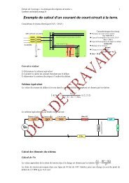
1. Calcul du courant d’emploi :<br />
S( kVA)<br />
120<br />
Ib( A)<br />
=<br />
= = 315A<br />
U( kV ) × 3 0,22×<br />
3<br />
2. Dimensionnement <strong>de</strong> la canalisation (Intensité admissible et Protection contre les surcharges)<br />
2.1 Choix du dispositif <strong>de</strong> protection : DUG Disjoncteur d’Usage Général<br />
2.2 Réglage du disjoncteur Irth ≥ Ib soit : Irth = 320A<br />
2.3 Mo<strong>de</strong> <strong>de</strong> pose : Enterré N°63<br />
2.4 Métho<strong>de</strong> <strong>de</strong> référence : D<br />
2.5 Nature <strong>de</strong> l’isolation : PRC (3 Ames Cuivre)<br />
2.6 Facteurs <strong>de</strong> correction :<br />
• Canalisation sous conduit non f 1 = 1<br />
• Température du sol 20°C f 2 = 1<br />
• Terrain Sec oui f 3 = 1<br />
• Pose non jointive non f 4 = 1<br />
f<br />
= f1 × f2<br />
× f3<br />
× f4<br />
= 1<br />
1 Pour dimensionner correctement une canalisation, il faut respecter les 5 ou 6 étapes fondamentales 1- Intensité<br />
admissible 2- Protection contre les surcharges. 3- Chute <strong>de</strong> tension. 4- Protection contre les courts-circuits. 6-<br />
Protection contre les contacts indirects. 6- Section économique (facultatif).<br />
2 <strong>Le</strong>s <strong>qu<strong>est</strong>ion</strong>s ne sont pas dans l’ordre : <strong>qu<strong>est</strong>ion</strong> 1 → 2, Vous ne pouvez pas calculer la chute <strong>de</strong> tension en ligne si vous<br />
ne connaissez pas l’intensité en ligne.<br />
3 La section <strong>de</strong>s conducteurs <strong>de</strong> phases constituant la canalisation n’<strong>est</strong> pas donnée. En premier lieu, il convient <strong>de</strong><br />
dimensionner celle-ci ou <strong>de</strong> vérifier l’existant. La section du conducteur Pe n’<strong>est</strong> pas l’image <strong>de</strong>s conducteurs <strong>de</strong> phases.
2.7 Intensité fictive :<br />
' k Irth<br />
I<br />
3 × 1×<br />
315<br />
z = = = 315A<br />
f 1<br />
2.8 Section minimale lue sur 52 J <strong>de</strong> la NFC 15-100 :<br />
S = 120mm²<br />
Cuivre<br />
3. Calcul <strong>de</strong> la chute <strong>de</strong> tension<br />
Pour simplifier le problème, je vais prendre les valeurs <strong>de</strong>s impédances (tous calculs faits) indiquées dans le<br />
dans le document joint à <strong>votre</strong> <strong>qu<strong>est</strong>ion</strong> 4 .<br />
3.1 Chute <strong>de</strong> tension triphasée 5 en Volts<br />
Z( Ω / km) × I( A) × l( m)<br />
∆u3( V ) =<br />
1000<br />
3.2 Chute <strong>de</strong> tension en %<br />
∆u3( V ) × 100<br />
∆u<br />
(%)<br />
=<br />
220<br />
3.3 Tableau récapitulatif<br />
Section<br />
(mm²)<br />
Impédance<br />
Z en Ω / km<br />
Chute <strong>de</strong> tension<br />
Volts (∆u triphasée) %<br />
120 0,36 18,43 8,38<br />
150 0,31 15,87 7,21<br />
185 0,27 13,82 6,28<br />
240 0,23 11,78 5,35<br />
300 0,2 10,24 4,65<br />
Note : N’oubliez pas que la chute <strong>de</strong> tension dont la valeur <strong>est</strong> fixée dans la norme (8% pour un abonné<br />
propriétaire <strong>de</strong> son transformateur) concerne le point le plus éloigné <strong>de</strong> la distribution (Canalisations<br />
principales + circuits terminaux). En conséquence, vous ferez le meilleur choix en tenant compte <strong>de</strong> la chute<br />
<strong>de</strong> tension d’une part entre le transformateur et le TGBT et d’autre part en fonction <strong>de</strong>s circuits en aval <strong>de</strong><br />
la liaison étudiée. La valeur <strong>de</strong> 10kA que vous indiquez dans <strong>votre</strong> <strong>qu<strong>est</strong>ion</strong> laisse supposer que la longueur <strong>de</strong><br />
câbles entre le TGBT et le transformateur n’<strong>est</strong> pas négligeable. En effet Ik3 aux bornes du<br />
transformateur <strong>est</strong> <strong>de</strong> l’ordre <strong>de</strong> 35kA<br />
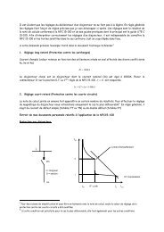
Pour vous ai<strong>de</strong>r à déterminer rapi<strong>de</strong>ment la bonne section d’une canalisation, en ayant bien entendu fixé les<br />
paramètres : courants d’emploi, limite <strong>de</strong> la chute <strong>de</strong> tension et longueur, vous trouverez un monogramme<br />
pratique.<br />
4. Choix du disjoncteur<br />
<strong>Le</strong> catalogue LEGRAND donne par exemple : Disjoncteur DPX 630 3P3D 320A, Icu = 36kA Ref 255 22.<br />
(Voir page 719 du catalogue).<br />
4 <strong>Le</strong> gui<strong>de</strong> pratique UTEC 15-105 donne à la page 86 la formule permettant <strong>de</strong> calculer la chute <strong>de</strong> tension.<br />
5 La colonne ∆u du tableau joint précise qu’il s’agit <strong>de</strong> la tension entre phase (chute <strong>de</strong> tension triphasée)
5. Commentaires et Conclusion<br />
5.1 Vous ferez le point avec vos professeurs en ce qui concerne certains développements absents<br />
volontairement <strong>de</strong> cette réponse. Une partie du travail vous incombe.<br />
5.2 L’étu<strong>de</strong> <strong>de</strong> cette installation <strong>est</strong> loin d’être terminée. Il vous appartient si vous désirez réaliser une<br />
installation conforme à la réglementation et en particulier à la NFC 15-100 <strong>de</strong> poursuivre celle-ci en<br />
étudiant la protection contre les courts-circuits (court-circuit maximal, minimal, courant <strong>de</strong> défaut,<br />
contraintes thermiques maximales) et la protection contre les contacts indirects. Cette partie ne<br />
pourra être étudiée que lorsque vous aurez précisé le Schéma <strong>de</strong>s liaisons à la terre (Régime du<br />
neutre), le couplage du transformateur, la tension <strong>de</strong> court-circuit, etc.<br />
5.3 Cette étu<strong>de</strong> peut être menée qu’avec une connaissance parfaite <strong>de</strong> la norme et <strong>de</strong> ses gui<strong>de</strong>s<br />
pratiques.
1,5 2<br />
1<br />
Document Jean-Marie BEAUSSY<br />
10 2 2<br />
3 320A 4<br />
5<br />
Ib en Ampères pour un chute <strong>de</strong> tension<br />
donnée en %<br />
1% 2% 3% 4% 5%<br />
10 3<br />
9<br />
8<br />
7<br />
6<br />
5<br />
10 3<br />
9<br />
4<br />
8<br />
7<br />
10 3<br />
3<br />
6<br />
9<br />
5<br />
8<br />
10 3<br />
7<br />
9<br />
2<br />
4<br />
6<br />
8<br />
10 3<br />
3<br />
7<br />
9<br />
5<br />
8<br />
6<br />
7<br />
4<br />
5<br />
6<br />
9<br />
8<br />
4<br />
3<br />
7<br />
2<br />
6<br />
3<br />
Ib (A)<br />
Section<br />
minimale 240²<br />
300 2<br />
240 2<br />
185 2 150²<br />
120²<br />
95 2 70 2 50 2 35 2 25 2 16 2 10 2 6 2 4 2 2,5 2<br />
5<br />
10 2<br />
2<br />
4<br />
9<br />
8<br />
7<br />
10 2<br />
2<br />
3<br />
2<br />
6<br />
5<br />
4<br />
3<br />
9<br />
8<br />
7<br />
6<br />
5<br />
4<br />
10 2<br />
9<br />
8<br />
7<br />
6<br />
5<br />
10 2<br />
9<br />
8<br />
7<br />
6<br />
10<br />
2<br />
3<br />
4<br />
5<br />
3<br />
4<br />
2<br />
3<br />
10<br />
2<br />
2<br />
10<br />
10<br />
10<br />
10 2 3 4 5 6 7 8 9 10 2 2 3 4 5 6 7 8 9 10 3<br />
160m<br />
Longueur en mètres<br />
CHOIX D'UNE SECTION POUR UNE INTENSITE, UNE CHUTE DE<br />
TENSION en % et UN COS ϕ DONNE<br />
Paramètres<br />
Uph/ph Cos ϕ<br />
237 0,8<br />
N° du tableau<br />
Chute Cu 001<br />
folio 1/14
IV<br />
LES PRODUITS<br />
IV.2 / LES DISJONCTEURS ET LES INTERRUPTEURS DPX<br />
<strong>Le</strong>s disjoncteurs et<br />
les interrupteurs DPX<br />
De 16 à 1600 A en six tailles <strong>de</strong> boîtiers seulement,<br />
avec une auxiliarisation commune et <strong>de</strong>s solutions<br />
<strong>de</strong> raccor<strong>de</strong>ment multiples, les disjoncteurs DPX<br />
procurent une facilité d’installation inégalée.<br />
À partir <strong>de</strong> 40 A, les disjoncteurs électroniques offrent<br />
un réglage très précis <strong>de</strong>s seuils <strong>de</strong> protection.<br />
Différentes versions, extractibles, débrochables,<br />
motorisées, permettent <strong>de</strong> répondre à toutes les<br />
exigences <strong>de</strong> continuité <strong>de</strong> service<br />
et <strong>de</strong> maintenabilité.<br />
DPX 125<br />
DPX 250 ER avec bloc<br />
différentiel latéral<br />
DPX 1600 électronique<br />
DPX 630 DPX-H 630 DPX 1600 DPX-H 1600<br />
Icu sous 400 V 36 kA 70 kA 50 kA 70 kA<br />
Ui (V) 690 690 690 690<br />
Pôles 3 P 3 P + N/2 4 P 3 P 3 P + N/2 4 P 3 P 3 P + N/2 3 P 3 P + N/2<br />
In (A) 320 255 22 255 32 255 37 255 42 255 52 255 57<br />
400 255 23 255 33 255 38 255 43 255 53 255 58<br />
500 255 25 255 35 255 39 255 45 255 55 255 59<br />
630 255 24 255 34 255 40 255 44 255 54 255 60 258 01 258 08 258 15 258 22<br />
800 258 02 258 09 258 16 258 23<br />
1000 258 03 258 10 258 17 258 24<br />
1250 258 04 258 11 258 18 258 25<br />
2<br />
DISJONCTEURS ÉLECTRONIQUES DPX ET DPX-H<br />
DPX 250 DPX-H 250 DPX 630 DPX-H 630 DPX 1600 DPX-H 1600<br />
Icu sous 400 V 36 kA 70 kA 36 kA 70 kA 50 kA 70 kA<br />
Ui (V) 630 630 690 690 690 690<br />
Pôles 3 P 4 P (1) 3 P 4 P (1) 3 P 4 P (1) 3 P 4 P (1) 3 P 4 P (1) 3 P 4 P (1)<br />
In (A) 40 254 01 254 07 254 13 254 19<br />
100 254 03 254 09 254 15 254 21<br />
160 254 04 254 10 254 16 254 22<br />
250 254 05 254 11 254 17 254 23 256 01 256 05 256 34 256 38<br />
400 256 02 256 06 256 35 256 39<br />
630 256 03 256 07 256 36 256 40 257 01 257 05 257 33 257 37<br />
800 257 02 257 06 257 34 257 38<br />
1250 257 03 257 07 257 35 257 39<br />
1600 257 04 257 08 257 36 257 40<br />
(1) Neutre réglable 0 - 50 - 100 %<br />
1<br />
DISJONCTEURS MAGNÉTOTHERMIQUES DPX ET DPX-H<br />
DPX 125 DPX 160<br />
Icu sous 400 V 25 kA 36 kA 25 kA 50 kA<br />
Ui (V) 500 500 500 500<br />
Pôles 3 P 3 P + N/2 4 P 3 P 3 P + N/2 4 P 3 P 3 P + N/2 4 P 3 P 3 P + N/2 4 P<br />
In (A) 16 250 36 250 44 250 50 250 58<br />
25 250 37 250 45 250 51 250 59 251 21 251 29 251 61 251 69<br />
40 250 38 250 46 250 52 250 60 251 22 251 30 251 62 251 70<br />
63 250 39 250 47 250 53 250 61 251 23 251 31 251 63 251 71<br />
100 250 40 250 42 250 48 250 54 250 56 250 62 251 24 251 26 251 32 251 64 251 66 251 72<br />
125 250 41 250 43 250 49 250 55 250 57 250 63<br />
160 251 25 251 27 251 33 251 65 251 67 251 73<br />
3<br />
4<br />
DISJONCTEURS DE BRANCHEMENT VERSION EDF<br />
In (A)<br />
90 130 170 240 320 400<br />
DPX 250 ER AB 252 90 252 91 252 92 252 93<br />
DPX 400 AB 255 93 255 94 255 95<br />
INTERRUPTEURS À DÉCLENCHEMENT LIBRE DPX-I<br />
LES PRODUITS<br />
DPX 250 ER DPX 250 DPX-H 250<br />
Icu sous 400 V 25 kA 50 kA 36 kA 70 kA<br />
Ui (V) 500 500 690 690<br />
Pôles 3 P 3 P + N/2 4 P 3 P 3 P + N/2 4 P 3 P 3 P + N/2 4 P 3 P 3 P + N/2 4 P<br />
In (A) 25 252 01 252 11<br />
40 252 02 252 12 253 28 253 45 253 52 253 69<br />
63 252 03 252 13 253 29 253 46 253 53 253 70<br />
100 252 04 252 14 252 44 252 54 253 30 253 40 253 47 253 54 253 64 253 71<br />
160 252 05 252 08 252 15 252 45 252 48 252 55 253 31 253 41 253 48 253 55 253 65 253 72<br />
250 252 06 252 09 252 16 252 46 252 49 252 56 253 32 253 42 253 49 253 56 253 66 253 73<br />
DPX-I 125 DPX-I 160 DPX-I 250 ER DPX-I 250 DPX-I 630 DPX-I 1600<br />
Pôles 3 P 4 P 3 P 4 P 3 P 4 P 3 P 4 P 3 P 4 P 3 P 4 P<br />
In (A) 125 250 98 250 99<br />
160 251 98 251 99 252 96 252 97<br />
250 252 98 252 99 253 98 253 99<br />
400 255 96 255 97<br />
630 255 88 255 89<br />
800 257 94 257 95<br />
1250 257 96 257 97<br />
1600 257 98 257 99<br />
718<br />
719