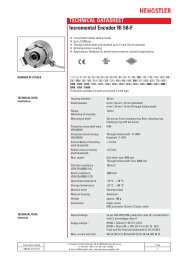
3. Montage Assembly Montage Montaggio ... - Hengstler GmbH
3. Montage Assembly Montage Montaggio ... - Hengstler GmbH
3. Montage Assembly Montage Montaggio ... - Hengstler GmbH

Create successful ePaper yourself
Turn your PDF publications into a flip-book with our unique Google optimized e-Paper software.
2. Safety<br />
2. Sécurité<br />
Hotline<br />
+49 (0) 74 24 / 89 - 539<br />
HENGSTLER <strong>GmbH</strong><br />
Uhlandstr. 49<br />
D-78554 Aldingen<br />
http://www.hengstler.de<br />
e-mail: info@hengstler.de<br />
Art. No.: 2 541 069<br />
Absoluter Drehgeber<br />
AC 36 SSI + BiSS<br />
Installationsanleitung<br />
Absolute Shaft Encoders<br />
AC 36 SSI + BiSS<br />
Installation instructions<br />
Capteur angulaire absolu<br />
AC 36 SSI + BiSS<br />
Instructions d´installation<br />
Trasduttori assoluti di velocità angolare<br />
AC 36 SSI + BiSS<br />
Istruzioni di installazione<br />
Transmisores giratorios absolutos<br />
AC 36 SSI + BiSS<br />
Instrucciones de instalación<br />
Edition.: 3 310713 TK<br />
Authorised persons<br />
The encoder should only be assembled and dismantled by a qualified<br />
electrician, as the unit contains sensitive electronic circuits.<br />
Risk of injury due to rotating shafts<br />
Hair and items of clothing may become caught up in rotating shafts.<br />
Prior to commencing all works, disconnect all power supplies and<br />
ensure that the working environment is Safe!<br />
Risk of destruction due to static electricity<br />
The CMOS modules contained in the encoder are very sensitive to high<br />
voltages such as can arise due to friction of the clothing.<br />
Do not touch plug contacts or electronic components!<br />
Risk of destruction due to mechanical overload<br />
Rigid mounting will give rise to constraining forces which will permanently<br />
overload the bearings.<br />
Never restrict the freedom of movement of the encoder! Use only the<br />
enclosed sheet steel springs or a suitable coupling to secure the unit!<br />
Risk of destruction due to mechanical shock<br />
Violent shocks, e.g. due to hammer blows, can lead to the destruction of<br />
the optical sensing system and the ball bearings.<br />
Never use force! <strong>Assembly</strong> is simple provided that correct procedure is<br />
followed.<br />
Risk of destruction due to overloading<br />
The unit may only be operated within the limits specified in the technical<br />
data.<br />
Fields of application: industrial processes and controls.<br />
Over voltage at the connecting terminals must be limited to over voltageclass-II<br />
values (SELV).<br />
The connecting cable is not for dragline mounting, only for fix mounting.<br />
This encoder is a supply part destined for mounting to an appliance (motor,<br />
machine). It is not provided for customer sale.<br />
Manufacturers integrating this encoder to their facilities are responsible as<br />
well for compliance with CE guidelines as for the CE mark.<br />
Personnel autorisé<br />
Du fait que le codeur renferme des circuits électroniques sensibles, seul le<br />
personnel compétent est autorisé à monter ou démonter le codeur.<br />
Mise en garde contre les arbres en rotation<br />
Les cheveux et les vêtements peuvent être happés par les arbres en<br />
rotation.<br />
Prière de sécuriser I'environnement de travail avant de mettre les<br />
machines en service.<br />
Risque de destruction par des décharges électrostatiques<br />
Les composants CMOS contenus dans le codeur sont très sensibles aux<br />
décharges électrostatiques provoquées par exemple par le frottement de<br />
certains vêtements.<br />
Ne pas toucher aux contacts enfichables ni aux composants électroniques.<br />
Risque de destruction par des surcharges mécaniques<br />
Une fixation rigide conduit à une contrainte permanente sur les paliers due<br />
aux forces de réaction.<br />
Ne jamais entraver le mouvement de l’arbre du codeur. Pour la fixation,<br />
utiliser uniquement les tôles élastiques à ressorts livrées avec le codeur<br />
ou un accouplement adéquat.<br />
Risque de destruction par des chocs mécaniques<br />
De fortes vibrations ou des chocs, par ex. des coups de marteau, peuvent<br />
provoquer la destruction du système optique de balayage du codeur et des<br />
roulements à billes.<br />
Ne jamais forcer. Un montage correct permet un assemblage facile des<br />
éléments.<br />
Risque de destruction par surcharge<br />
Mettre l’appareil en œuvre uniquement dans les limites prescrites sur<br />
les notices techniques.<br />
Domaine d'application : commandes et processus industriels.<br />
Les surtensions sur les bornes de raccordement doivent êtres limitées aux<br />
valeurs de la catégorie II concernant les surtensions (SELV).<br />
Ce codeur correspond à une fourniture prévue pour être intégrée dans un<br />
appareil (moteur, partie mécanique). II n'est pas destiné à la vente directe<br />
au client final.<br />
Le constructeur intégrant ce codeur dans son équipement est tenu de<br />
respecter les directives CE ainsi que le marquage CE.<br />
1. Vorwort<br />
2. Sicherheitshinweise<br />
2. Avvertenze sulla Sicurezza<br />
2. Seguridad<br />
Dieses Anleitung soll Ihnen den Anschluss und die Inbetriebnahme<br />
des Drehgebers ermöglichen.<br />
Weitere Informationen finden Sie im Drehgeberkatalog bzw. erhalten<br />
Sie auf Anfrage oder per Download von unserer Internetseite.<br />
www.hengstler.de<br />
1. Preface<br />
These installation instruductions are provided for the connection and<br />
starting procedure of your shaft encoder.<br />
You will get further information from the Acuro datasheet, on request<br />
or on download from our Internet site.<br />
www.hengstler.de<br />
1. Avant-propos<br />
Ces instructions ont pour but de vous permettre la mise en route du<br />
capteur angulaire.<br />
Vous trouverez de plus amples informations dans le fiche technique<br />
ou sur simple demande ou par téléchargement à partir de notre site<br />
Internet.<br />
www.hengstler.de<br />
1. Introduzione<br />
Questo manuale dínstallazione ha il compito di darle la possibilità di<br />
allaciare e mettere in funzione i trasduttori.<br />
Ulteriori informazioni riceve del folgio caratteristiche o a richiesta o<br />
servitevi die download nel nostro sito internet.<br />
www.hengstler.de<br />
1. Préambulo<br />
Este manual de instalación le permite la conexión y puest en marcha<br />
de los transmisores giratorios.<br />
Encontrará mayor información en el hoja de especificaciones o<br />
obtenerá esta en ruego, o bien, solicítela directamente a nuestra<br />
empresa.<br />
www.hengstler.de<br />
Befugte Personen<br />
Der Drehgeber darf nur von einer Elektrofachkraft montiert und demontiert<br />
werden, da im Drehgeber empfindliche elektronische Schaltkreise enthalten<br />
sind.<br />
Verletzungsgefahr durch rotierende Wellen<br />
Haare und Kleidungsstücke können von rotierenden Wellen erfasst werden.<br />
Vor allen Arbeiten alle Betriebsspannungen ausschalten und Arbeitsumgebung<br />
sichern!<br />
Zerstörungsgefahr durch Körperelektrizität<br />
Die CMOS-Bausteine im Drehgeber sind sehr empfindlich gegen hohe<br />
Spannungen, wie sie z. B. durch die Reibung der Kleidung entstehen<br />
können.<br />
Steck-Kontakte und elektronische Komponenten nicht berühren!<br />
Zerstörungsgefahr durch mechanische Überlastung<br />
Eine starre Befestigung führt zu dauerhafter Überlastung der Lager durch<br />
Zwangskräfte.<br />
Die Beweglichkeit der Geberwelle niemals einschränken! Zur Befestigung<br />
nur die beigelegten Federbleche oder eine geeignete Kupplung<br />
verwenden!<br />
Zerstörungsgefahr durch mechanischen Schock<br />
Starke Erschütterungen, z. B. Hammerschläge, können zur Zerstörung der<br />
optischen Abtastung und der Kugellager führen.<br />
Niemals Gewalt anwenden! Bei sachgemäßer <strong>Montage</strong> lässt sich alles<br />
leichtgängig zusammenfügen.<br />
Zerstörungsgefahr durch Überlastung<br />
Das Gerät darf nur innerhalb der Grenzen betrieben werden, wie sie in<br />
den technischen Daten vorgegeben sind.<br />
Anwendungsbereich: Industrielle Prozesse und Steuerungen.<br />
Überspannungen an den Anschlussklemmen müssen auf Werte der<br />
Überspannungskategorie II begrenzt werden (SELV).<br />
Das Anschlusskabel ist nicht schleppfähig und nur für feste Verlegung<br />
geeignet.<br />
Dieser Geber ist ein Zulieferteil, das für den Einbau in ein Gerät (Motor,<br />
Maschine) vorgesehen ist. Er ist nicht für den Verkauf an den Endkunden<br />
bestimmt.<br />
Der Hersteller, der diesen Geber in sein Gerät integriert, ist verantwortlich<br />
für die Einhaltung der CE-Richtlinien und die CE-Kennzeichnung.<br />
Persone autorizzate<br />
Il trasduttore di rotazione può essere montato e smontato solo da un<br />
elettricista specializzato, poiché il trasduttore di rotazione è dotato di circuiti<br />
elettronici sensibili.<br />
Pericolo di lesioni dovute ad alberi in rotazione<br />
I capelli e gli indumenti possono impigliarsi negli alberi in rotazione.<br />
Prima di eseguire qualsiasi lavoro disinserire tutte le tensioni d’esercizio<br />
e proteggere la zona di lavoro!<br />
Pericolo di distruzione dovuta all'elettricità formatasi nel corpo<br />
I componenti CMOS del trasduttore di rotazione sono molto sensibili alle<br />
alte tensioni come quelle che possono formarsi in seguito allo strofinio degli<br />
indumenti.<br />
Non toccare i connettori a spina ed i componenti elettronici!<br />
Pericolo di distruzione dovuta a sovraccarico meccanico<br />
Un fissaggio troppo rigido provoca un sovraccarico permanente dei<br />
cuscinetti per via delle forze ad azione forzata.<br />
Non limitare mai la mobilità dell’albero del trasduttore! Per il fissaggio<br />
utilizzare solo le lamiere elastiche in dotazione oppure un giunto<br />
adeguato!<br />
Pericolo di distruzione dovuta a shock meccanico<br />
Forti urti, ad esempio i colpi di martello, possono causare la distruzione del<br />
sistema di scansione ottica e dei cuscinetti a sfera.<br />
Non usare violenza! Lavorando appropriatamente si può unire tutto più<br />
leggermente.<br />
Pericolo di distruzione dovuta a sovraccarico.<br />
Fare funzionare l’apparecchio entro i limiti che sono stati specificati nelle<br />
caratteristiche tecniche<br />
Campo d'impiego: processi industriali e dispositivi di comando.<br />
Le sovratensioni sui morsetti devono essere limitate ai valori della categoria<br />
di sovratensione II (SELV).<br />
Questo trasduttore è un elemento complementare destinato al montaggio in<br />
un apparecchio (motore,macchina), e non può essere venduto al cliente<br />
finale.<br />
Il produttore che incorpora questo trasduttore nel suo apparecchio è tenuto<br />
a far rispettare le direttive CE e a farlo contrassegnare col marchio CE.<br />
Persona autorizada<br />
Dado que el codificador rotatorio contiene circuitos electrónicos sensibles,<br />
únicamente un electricista especializado está autorizado a montarlo y a<br />
desmontarlo.<br />
Peligro de lesión mediante ejes en rotación<br />
Los cabellos y las prendas de vestir pueden ser arrastrados por los ejes en<br />
rotación.<br />
¡Antes de comenzar cualquier trabajo, desconecte todas las tensiones<br />
de alimentación y asegúre el entorno de trabajo!<br />
Peligro de destrucción por electricidad electrostática<br />
Los componentes de CMOS del codificador rotatorio son muy sensibles a<br />
las altas tensiones, que se producen p.ej. por el frotamiento de la ropa.<br />
¡No toque los contactos enchufables y componentes electrónicos!<br />
Peligro de destrucción por sobrecarga mecánica<br />
Un soporte rígido produce una sobrecarga permanente de los cojinetes<br />
ocasionada por las fuerzas de ligadura.<br />
¡No limite nunca la libertad de movimiento del eje del codificador! ¡Para<br />
fijarlo, utilice únicamente las chapas elásticas adjuntadas o un<br />
dispositivo de acoplamiento adecuado!<br />
Peligro de destrucción por choque mecánico<br />
Las vibraciones fuertes, p.ej. las que se producen por los golpes de un<br />
martillo, pueden destruir el dispositivo de exploración óptica y los<br />
rodamientos de bolas.<br />
¡No recurra nunca a la violencia! El montaje es sencillo, siempre y<br />
cuando se sigan los pasos correctos.<br />
Peligro de destrucción por sobrecarga<br />
No está permitido utilizar el aparato fuera de los límites prescritos en la<br />
hoja de datos técnicos.<br />
Campo de aplicación: Procesos industriales y unidades de mando.<br />
Es imprescindible limitar las sobretensiones en los bornes de conexión a<br />
los valores correspondientes a la categoría de sobretensión II (SELV).<br />
Este codificador forma parte del suministro y está destinado a la instalación<br />
en un aparato (motor, máquina). No está previsto para la venta al cliente.<br />
Todo fabricante, que integre este codificador en uno de sus aparatos, se<br />
responsabiliza por el cumplimiento de la normativa CE y de la marca CE.<br />
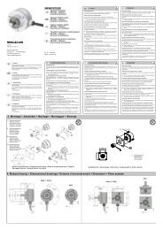
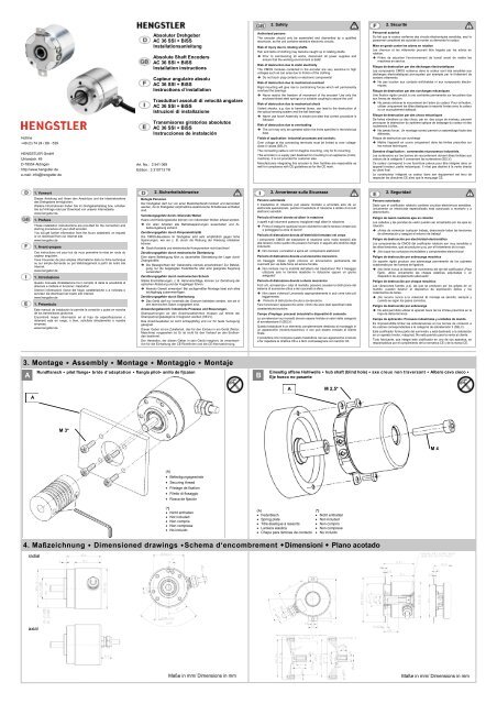
<strong>3.</strong> <strong>Montage</strong> • <strong>Assembly</strong> • <strong>Montage</strong> • <strong>Montaggio</strong> • Montaje<br />
A<br />
Rundflansch • pilot flange• bride d‘adaptation • flangia pilot• anillo de fijcaion<br />
B<br />
Einseitig offene Hohlwelle • hub shaft (blind hole) • axe creux non traversant • Albero cavo cieco •<br />
Eje hueco no pasante<br />
A<br />
M 2,5*<br />
A<br />
M 3*<br />
M 4<br />
(A)<br />
Befestigungsgewinde<br />
Securing thread<br />
Filetage de fixation<br />
Filetto di fissaggio<br />
Rosca de fijación<br />
(*)<br />
Nicht enthalten<br />
Not included<br />
Non compris<br />
Non comprese<br />
No incluido<br />
(A)<br />
Federblech<br />
Spring plate<br />
Tôle élastique à ressorts<br />
Lamiera elastica<br />
Chapa para láminas de contacto<br />
(*)<br />
Nicht enthalten<br />
Not included<br />
Non compris<br />
Non comprese<br />
No incluido<br />
4. Maßzeichnung • Dimensioned drawings •Schema d‘encombrement •Dimensioni • Plano acotado<br />
radial<br />
axial<br />
Maße in mm/ Dimensions in mm<br />
Maße in mm/ Dimensions in mm
4. Mechanische Daten<br />
Mechanical data • Caractéristiques mécaniques<br />
Dati meccanici • Datos mecánicos<br />
d = 6 mm<br />
Betrieb<br />
Operation<br />
De fonctionnement<br />
Esercizio<br />
Servicio<br />
Schock/ Schwing<br />
Shock/ Vibration<br />
Résistance aux<br />
chocs/ Vibration<br />
Résistance<br />
Resistenza<br />
all‘urto/ Limite<br />
di fatica<br />
Resit. a golpes/<br />
Resist. A las<br />
vibrationes<br />
kurzzeitig<br />
short term<br />
brièvement<br />
per breve durata<br />
de corta duración<br />
Dauerbetrieb<br />
continuous duty<br />
Fonctionnement<br />
ininterrompu<br />
Servizio continuo<br />
Funcionamiento<br />
continuo<br />
-40 ... +100 °C<br />
= 12 000 min -1<br />
= 10 000 min -1<br />
1 000 m/s² (6 ms)<br />
100 m/s² (10 ... 2 000 Hz)<br />
5. Elektrische Daten<br />
Electrical data • Caractéristiques électriques<br />
Dati elettrici • Datos eléctricos<br />
Attention<br />
Singleturn<br />
Multiturn<br />
UB 1) 2) 3)<br />
DC 5 V – 5%/ +10%<br />
DC 7 - 30 V<br />
Imax (only Encoder) = 50 mA 100 mA<br />
Imax (incl. Output) =<br />
Fuse<br />
Alarmausgang<br />
Alarm output<br />
Sortie d´alarme<br />
Carico dúscita<br />
Salida de alarma<br />
Kabellänge<br />
Cable length<br />
Longueur de câble<br />
Lunghezza cavo<br />
Longitud de cable<br />
ESD<br />
150 mA 200 mA<br />
Alarm Bit (SSI-Option)<br />
Warnbit + Alarmbit (BiSS)<br />
max. 400 m 2)<br />
1) Der Anschluss an ein Gleichspannungsnetz ohne EMV-Schutzbeschaltung ist nicht<br />
zulässig. Bei Kabellängen > 10 m ist immer eine zusätzliche Schutzbeschaltung<br />
erforderlich!<br />
2) = L Baudrate<br />
Attention<br />
It is not allowed to connect the encoder to a direct current line voltage without protective<br />
circuit for EMC. For cable lengths > 10 m a protective circuit is always necessary!<br />
< 25 m < 1 MHz<br />
< 50 m < 400 kHz<br />
< 100 m < 300 kHz<br />
< 200 m < 200 kHz<br />
< 400 m < 100 kHz<br />
Bitte beachten: Bei einer Versorgungsspannung von 5V in Verbindung mit einer großen<br />
Leitungslänge entsteht ein Spannungsabfall!<br />
Please note: When using 5V power supply and long cables a fall of voltage will emerge!<br />
3) Bei 5V Versorgungsspannung besteht kein Verpolschutz!<br />
For 5V power supply there is no inverse-polarity protection<br />
L<br />
6.2 Kabel • cable • câble • Cavo • cable<br />
Signal<br />
4) = Nur bei „SC“, „SD“, „BC“, „BV“<br />
Only when „SC“, „SD“, „BC“, „BV“<br />
Farbe • Colour • Couleur • Cavi • Color<br />
Alte Belegung bei BI, SG,<br />
SB • Old assignment for BI,<br />
SG, SB<br />
Alte Belegung bei SC • Old<br />
assignment for SC<br />
Neue Belegung für alle Anschlüsse•<br />
New assignment for<br />
all connections<br />
5/7-30V (UB) ge/ sw ge/ sw<br />
ws<br />
0 V (UN) ws/ gn ws/ gn<br />
br<br />
Clock ws ws<br />
ge<br />
Clock br br<br />
gn<br />
Data sw sw<br />
rs<br />
Data vi vi<br />
gr<br />
A n.c. gn<br />
ws/ gn 4)<br />
A n.c. ge<br />
br/ gn 4)<br />
B n.c. bl<br />
rt/ bl 4)<br />
B n.c. rt<br />
gr/ rs 4)<br />
5 V Sensor n.c. rt/ sw<br />
vi 4)<br />
0 V Sensor n.c. br/ gn<br />
sw 4)<br />
6. Anschlussbilder<br />
Connection diagrams • Symboles de raccrdement<br />
Denominazione collegamento • Denominación de los cables<br />
6.1 Farbkürzel für Kabel<br />
Colour code for cable • Abréviation de couleur de câble<br />
Abbreviature per cavi • Abreviatura de color para cable<br />
ID<br />
bl blau blue bleu blu azul<br />
br braun brown brun marrone marrón<br />
ge gelb yellow jaune giallo amarillo<br />
gn grün green vert verde verde<br />
gr grau grey gris grigio gris<br />
rs rosa pink rose rosa rosa<br />
rt rot red rouge rosso rojo<br />
sw schwarz black noir nero negro<br />
vi violett violett violet viola violeta<br />
ws weiß white blanc bianco blanco<br />
7. Identifikationscode<br />
Ordering data • Code d´identification<br />
Chiave per l´ordinazione • Código de pedido<br />
Für BiSS-C / For BiSS-C<br />
7.1 Deutsch<br />
Typ Auflösung Versorgung 1) Flansch, Schutzart, Welle Ausgang Anschluss<br />
ADDRESS MAP<br />
Bank 0:<br />
Bank 1:<br />
configuration Memory<br />
manufactory Memory<br />
AC 36<br />
0012 12 Bit ST<br />
0013 13 Bit ST<br />
0014 14 Bit ST<br />
0016 16 Bit ST<br />
0017 17 Bit ST<br />
0019 19 Bit ST<br />
0022 22 Bit ST<br />
1212 12 Bit MT+12 Bit ST<br />
1213 12 Bit MT+13 Bit ST<br />
1214 12 Bit MT+14 Bit ST<br />
1217 12 Bit MT+17 Bit ST<br />
1219 12 Bit MT+19 Bit ST<br />
1222 12 Bit MT+22 Bit ST<br />
A DC 5 V 2)<br />
E DC 7-30 V<br />
1)<br />
Der Anschluss an ein Gleichspannungsnetz ohne EMV-Schutzbeschaltung ist nicht zulässig.<br />
Bei Kabellängen > 10 m ist immer eine zusätzliche Schutzbeschaltung erforderlich<br />
3)<br />
Kein Verpolschutz<br />
R.41 Rundflansch, IP64, Vollwelle<br />
F.1R Federblech, IP50, Hohlwelle<br />
8mm einseitig offen<br />
U.1R Federblech, IP50, Hohlwelle<br />
8mm einseitig offen<br />
SG SSI Gray<br />
SC SSI Gray + SinCos 1 Vss<br />
SB SSI Binär<br />
SD SSI Binär + SinCos 1 Vss<br />
BI BiSS-B<br />
BC BiSS-B + SinCos 1 Vss<br />
BE BiSS-C<br />
BV BiSS-C + SinCos 1 Vss<br />
A Kabel axial, 0,5 m<br />
A-D0 Kabel axial, 3 m<br />
A-F0 Kabel axial, 5 m<br />
A-K0 Kabel axial, 10 m<br />
B Kabel radial, 0,5 m<br />
B-D0 Kabel radial, 3 m<br />
B-F0 Kabel radial, 5 m<br />
B-K0 Kabel radial, 10 m<br />
Attention<br />
Bank 2: manufactory EDS General<br />
Bank 3: manufactory EDS Profile BP1<br />
Bank 4 - 7: OEM Memory<br />
Speicher kann überschrieben werden!<br />
Bitte beachten, dass Bank 0, 1, 2 und 3 nicht beschrieben werden dürfen.<br />
Memory can be overwritten!<br />
Please not that Bank 0, 1, 2 and 3 are not allowed to be accessed.<br />
7.2 English<br />
Type Resolution Supply Voltage 1) Flange, Protection, Shaft Output Connection<br />
AC 36<br />
0012 12 Bit ST<br />
0013 13 Bit ST<br />
0014 14 Bit ST<br />
0016 16 Bit ST<br />
0017 17 Bit ST<br />
0019 19 Bit ST<br />
0022 22 Bit ST<br />
1212 12 Bit MT+12 Bit ST<br />
1214 12 Bit MT+14 Bit ST<br />
1213 12 Bit MT+13 Bit ST<br />
1217 12 Bit MT+17 Bit ST<br />
1219 12 Bit MT+19 Bit ST<br />
1222 12 Bit MT+22 Bit ST<br />
A DC 5 V 2)<br />
E DC 7-30 V<br />
R.41 Pilot flange, IP64, solid shaft<br />
F.1R Spring tether, IP50, 8mm hub<br />
shaft<br />
U.1R Spring tether, IP50, 8mm hub<br />
shaft<br />
SG SSI Gray<br />
SC SSI Gray + SinCos 1 Vpp<br />
SB SSI Binary<br />
SD SSI Binary + SinCos 1 Vpp<br />
BI BiSS-B<br />
BC BiSS-B + SinCos 1 Vpp<br />
BE BiSS-C<br />
BV BiSS-C + SinCos 1 Vpp<br />
A Cable axial, 0,5 m<br />
A-D0 Cable axial, 3 m<br />
A-F0 Cable axial, 5 m<br />
A-K0 Cable axial, 10 m<br />
B Cable radial, 0,5 m<br />
B-D0 Cable radial, 3 m<br />
B-F0 Cable radial, 5 m<br />
B-K0 Cable radial, 10 m<br />
1)<br />
It is not allowed to connect the encoder to a direct current line voltage without a protective circuit for EMV.<br />
For cable lengths > 10 m a protective circuit is always necessary<br />
3)<br />
No inverse-polarity protection