Viking Power 16 - Johnson Pump
Viking Power 16 - Johnson Pump
Viking Power 16 - Johnson Pump

Create successful ePaper yourself
Turn your PDF publications into a flip-book with our unique Google optimized e-Paper software.
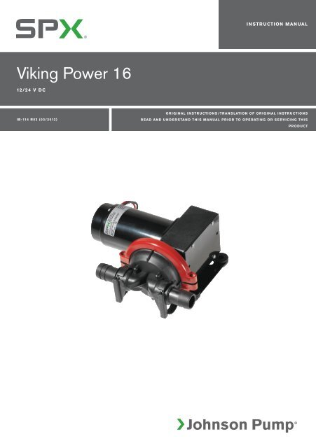
INSTRUCTION MANUAL<br />
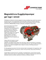
<strong>Viking</strong> <strong>Power</strong> <strong>16</strong><br />
12/24 V DC<br />
IB-114 R03 (03/2012)<br />
ORIGINAL INSTRUCTIONS/TRANSLATION OF ORIGINAL INSTRUCTIONS<br />
READ AND UNDERSTAND THIS MANUAL PRIOR TO OPERATING OR SERVICING THIS<br />
PRODUCT
Index - Indice<br />
Svenska......................................................................................................................................3<br />
English .......................................................................................................................................6<br />
Deutsch......................................................................................................................................9<br />
Français................................................................................................................................... 13<br />
Español.....................................................................................................................................17<br />
Italiano..................................................................................................................................... 21<br />
Parts List................................................................................................................................. 25<br />
Accessories............................................................................................................................ 26<br />
Dimensions..............................................................................................................................27<br />
Besök www.johnson-pump.com för mer information om vår världsomspännande organisation, våra godkännanden, certifieringar och lokala representanter. SPX<br />
Corporation förbehåller sig rätten att ändra design och material utan föregående avisering. Designelement, konstruktionsmaterial och dimensioner som beskrivs i denna<br />
bulletin gäller endast som information och skall alltid bekräftas skriftligt för att vara gällande.<br />
For more information about our worldwide locations, approvals, certifications, and local representatives, please visit www.johnson-pump.com. SPX Corporation<br />
reserves the right to incorporate our latest design and material changes without notice or obligation. Design features, materials of construction and dimensional data,<br />
as described in this bulletin, are provided for your information only and should not be relied upon unless confirmed in writing.<br />
Für weitere Informationen über unsere weltweiten Standorte, Zulassungen, Zertifizierungen und unsere Vertreter vor Ort, besuchen Sie bitte unsere Webseite:<br />
www.johnson-pump.com. Die SPX Corporation behält sich das Recht vor, die neuesten Konstruktions- und Werkstoffänderungen ohne vorherige Ankündigung und<br />
ohne Verpflichtung hierzu einfließen zu lassen. Konstruktive Ausgestaltungen, Werkstoffe sowie Maßangaben, wie sie in dieser Mitteilung beschrieben sind, sind nur<br />
zur Information. Alle Angaben sind unverbindlich, es sei denn, sie wurden schriftlich bestätigt.<br />
Pour plus d’information sur nos succursales internationales, nos approbations, nos certifications et nos représentants locaux, veuillez consulter notre site Internet au<br />
www.johnson-pump.com. SPX Corporation se réserve le droit d’incorporer nos plus récents concepts ainsi que tout autre modification importante sans préavis ou<br />
obligation. Les éléments décoratifs, matériaux de construction et les données dimensionnelles, tels qu’énoncés dans ce communiqué, sont fournis pour votre information<br />
seulement et ne doivent pas être considérés comme officiels à moins d’avis contraire par écrit.<br />
Para más información sobre nuestras oficinas a nivel mundial, aprobaciones, certificaciones y representantes locales, por favor visite www.johnson-pump.com. SPX<br />
Corporation se reserva el derecho de incorporar nuestro diseño más reciente y cambios materiales sin necesidad de notificación previa u obligación de ningún tipo.<br />
Características de diseño, materiales de construcción y dimensiones, tal y como están descritas en este boletín, son proporcionadas sólo con fines informativos y no<br />
deben ser usados como referencia a menos que sean confirmados por escrito.<br />
Per ottenere maggiori informazioni sulle nostre sedi nel mondo, autorizzazioni, certificazioni, e rappresentanti locali, potete visitare il sito www.johnson-pump.com.<br />
La SPX Corporation si riserva il diritto di apportare cambiamenti ai propri design e materiali senza preavviso o vincolo. Le caratteristiche del design, i materiali di<br />
costruzione e i dati dimensionali, così come descritti nel presente bollettino, sono forniti solo per vostra informazione e non saranno oggetto di obbligazione salvo<br />
autorizzazione confermata per iscritto.<br />
Recreational Craft Directive 94/25/EEC<br />
ISO8849: 2003 Electrically operated bilge pumps<br />
ISO 8846: 1990/Electrical devices -<br />
Protection against ignition of surrounding flammable gases<br />
EN ISO 10133: 2001/Electrical systems - Extra low-voltage DC installations<br />
Electromagnetic Compatibility Directive 89/336/EEC<br />
EN55014: 2000/Radio Disturbance<br />
Garanti 3 år<br />
Warranty 3 years<br />
Garantie 3 Jahren<br />
Garantie 3 ans<br />
Garantía 3 años<br />
Garanzia 3 anni
Svenska<br />
<strong>Viking</strong> <strong>Power</strong> <strong>16</strong> med 12/24 V motor<br />
Läs igenom installationsanvisningen noga innan montering av pumpen.<br />
Typiska användningsområden<br />
<strong>Viking</strong> <strong>Power</strong> <strong>16</strong> är en membran pump och det<br />
perfekta valet för duschläns, länspumpning och<br />
avfallsvatten. Den kompakta designen och flexibla<br />
konfigurationen gör att pumpen kan installeras i<br />
stort sett var som helst efter avloppet för gråvatten<br />
eller som länspump.<br />
Modeller<br />
<strong>Viking</strong> <strong>Power</strong> <strong>16</strong> 12V 10-13350-03<br />
<strong>Viking</strong> <strong>Power</strong> <strong>16</strong> 24V 10-13350-04<br />
Egenskaper<br />
• <strong>16</strong> L/min öppet flöde<br />
• 15 L/min vid 0.1 bar<br />
• Kompakt design<br />
• Snabbanslutningar (1" el. ¾" rak slanganslutning.<br />
90° som tillbehör.)<br />
• Tystgående<br />
• Självsugande upp till 3 m<br />
• <strong>Pump</strong>huvudet kan rotera 360°<br />
• Flexibel montering<br />
• Kan torrköras<br />
• Inget filter behövs<br />
• Kullagerstödd kraftöverföring<br />
• Låg strömförbrukning (30W)<br />
• Uppfyller ISO15083 (Small Craft Bilge <strong>Pump</strong><br />
standard for boats up to 12 m/40 ft)<br />
Funktionsprincip<br />
Enkammars, självsugande membranpump. För att<br />
uppnå god självsugande förmåga för en filterlös<br />
pump är pumpen designad med ett stort membran<br />
och ett långt slag. På detta sätt spolas mycket<br />
vatten genom pumphuset vid varje slag och på så<br />
sätt spolas smutspartiklar bort.<br />
Teknisk beskrivning<br />
<strong>Pump</strong>hus: Nylon<br />
Ventil: Nitril<br />
Membran: Armerad nitril<br />
Anslutn.: KlickTite XL anslutning<br />
1" el. ¾" rak slanganslutning.<br />
90° som tillbehör.<br />
Skruvar: Rostfritt stål<br />
Fot: Målad galvaniseras plåt<br />
Max. utloppshöjd: 3 m<br />
Översättning av originalinstruktionerna<br />
Max. lyft höjd: 3 m<br />
Max höjd+lyft: 4 m<br />
Motor: 30 W vid 0,1 bar<br />
12/24 V (Inbyggt termoskydd)<br />
Säkring: 8 A – 12V / 4 A – 24V<br />
<strong>Pump</strong>en är CE-märkt enl följande standarder:<br />
• EN55014-1:2000/Radiostörningar<br />
• EN55014-2:1997/Radiostörningar<br />
• ISO8846: Båtar – Elkomponenter – Skydd mot<br />
antändning av omgivande brännbara gaser<br />
• ISO8849:2003/Båtar – Elektriska länspumpar<br />
• ISO10133:2001/Båtar – Elektriska system –<br />
Klenspänningsinstallationer för likström<br />
Sprängskiss<br />
Se sidan 25<br />
Tryck- och kapacitetsdata<br />
Tryck Flöde Ampere<br />
Bar kPa Psi l/min USGPM 12V 24V<br />
0 0 0 <strong>16</strong>.2 4.2 2.0 1.0<br />
0.1 10 1.5 15.1 4.0 2.3 1.2<br />
0.2 20 2.9 13.7 3.6 2.8 1.4<br />
0.3 30 4.4 12.5 3.3 3.4 1.7<br />
0.4 40 5.8 11.3 3.0 4.0 1.9<br />
Erforderlig säkring 8 A 4 A<br />
Installation och skötsel<br />
Installation<br />
Montera pumpen i ett torrt utrymme.<br />
• Om pumpen monteras vertikalt ska motorn vara<br />
ovanför pumphuset.<br />
• Märk ut skruvhålen och borra styrhål.<br />
• Montera pumpen med rostfria skruvar, tillsammans<br />
med de bifogade brickorna. Kontrollera<br />
att distansbrickorna av plast är rätt placerade.<br />
OBS! Dra inte åt de vibrationsdämpande gummifötterna<br />
för hårt, (Skruvarna är för hårt dragna<br />
om pumphuset har kontakt med fästytan).<br />
• Armerad, böjlig slang rekommenderas.<br />
OBS! Backventilerna monteras med den<br />
spetsiga ändan i flödesriktningen. Se<br />
sprängskiss.<br />
• Använd rostfria slangklämmor för att fästa<br />
slangen på snabbanslutningarna och andra<br />
slangar i systemet.<br />
3
Svenska<br />
<strong>Pump</strong>konfiguration<br />
<strong>Pump</strong>en kan konfigureras på 3 sätt:<br />
• Med motorn till vänster<br />
• Med motorn till höger<br />
• Med motorn rakt upp<br />
Konfigureras enligt fäljande:<br />
1. Lossa 6 skruvar som håller pumpen på foten.<br />
2. Montera pumpen med motorn i önskat läge.<br />
3. Fäst de 6 skruvarna.<br />
Elektrisk installation<br />
<strong>Pump</strong>en ska installeras i enlighet med ISO 10133<br />
(Båtar - Elektriska system _ klenspänningsinstalltioner<br />
för likström) OBS! Säkringen ska vara<br />
av gnistskyddad typ.<br />
Motorn har ett termiskt överbelastningsskydd som<br />
skyddar motorn från överhettning. Skyddet återställs<br />
automatiskt när motorn svalnat. Om pumpen<br />
ansluts med separat jordningskabel ska denna<br />
vara gul/grön och anslutas på motorns fot. Se<br />
kopplingsschema (se nedan) för rätt installation.<br />
Negativ ledare ska vara svart.<br />
Välj kabeldimension efter total kabellängd (se tabell<br />
nedan). Kabelanslutningarna ska avtätas med<br />
ett marint tätningsmedel.<br />
Obs: Kontrollera före installation med elektriska<br />
styrsystem att utrustningen som ska<br />
användas har tillräcklig effekt för motorns<br />
strömstyrka. Låg spänning kan medföra att<br />
motorn överhettas.<br />
Underhåll och skötsel<br />
Ventilerna i pumphuset ska rengöras regelbundet<br />
för att undvika reducerad pumpeffekt. Detta görs<br />
genom att skruva loss klämmorna till pumphuset<br />
och öppna huset. OBS! Se till att strömmen är<br />
bruten då detta görs.<br />
Kopplingsschema<br />
Max 0.2 m<br />
–<br />
+<br />
Black<br />
Green/yellow<br />
Terminal<br />
fuse<br />
<strong>Pump</strong><br />
Switch<br />
Red<br />
Andra elektriska anordningar, t.ex. strömbrytare,<br />
reläer ska placeras mellan pump och<br />
batteriets pluspol (+) (på den röda kabeln).<br />
Kabelarea<br />
(baserat på 10% spänningsfall)<br />
Kabelarea Max kabellängd* i m<br />
12V 24V<br />
1.0 mm² #18 AWG 13 56<br />
1.5 mm² #<strong>16</strong> AWG 20 84<br />
2.5 mm² #14 AWG 34 140<br />
* Kabellängden är det totala avståndet från batteriet<br />
till pumpen och tillbaka till batteriet. Använd<br />
gärna ett relä för att korta av de strömförande<br />
ledarna.<br />
Självsugningsförmåga<br />
<strong>Pump</strong>en är självsugande upp till 3 m.<br />
Torrkörning<br />
<strong>Pump</strong>en kan torrköras utan att ta skada. Det kommer<br />
dock att reducera batteriet.<br />
Vinterförhållanden<br />
Töm pumpen på vatten genom att pumpa tills den<br />
suger luft och ingen vätska kommer från utloppet.<br />
Service instruktioner<br />
Byte av membran<br />
1. Ta bort de två skruvarna som håller klämmorna<br />
och ta bort dem<br />
2. Ta bort pumphuset<br />
3. Ta bort skruven som håller membranet och<br />
membranbrickan.<br />
4 Översättning av originalinstruktionerna
Svenska<br />
4. Ta bort membranet och membranbrickan.<br />
5. Montera det nya membranet och den nya membranbrickan<br />
med dennya skruven.<br />
6. Montera pumphuset och klämmorna.<br />
Byte av pumphus<br />
1. Ta bort de två skruvarna som håller klämmorna<br />
och ta bort dem<br />
2. Ta bort pumphuset<br />
3. Montera det nya pumphuset och klämmorna.<br />
Rengöring av ventilerna<br />
1. Ta bort de två skruvarna som håller klämmorna<br />
och ta bort dem<br />
2. Ta bort pumphuset<br />
3. Inspektera gummi beckventilerna och ta bort<br />
ev. skräp/smuts.<br />
4. Montera pumphuset och klämmorna.<br />
Avfallshantering/materialåtervinning<br />
Vid avfallshantering ska produkten lämnas för<br />
destruktion/återvinning enligt gällande lagstiftning.<br />
Vid tillämpliga fall demonteras och sorteras<br />
produkten i ingående materialfraktioner.<br />
Felsökningsschema<br />
Symptom Orsak Åtgärd<br />
1. <strong>Pump</strong>en går inte. 1.1 Utlöst termoskydd eller 1.1.1 Kontrollera säkringen. Låt motorn svalna<br />
defekt säkring.<br />
före omstart om den är överhettad.<br />
1.2 Felaktig kabelanslutning 1.2.1 Kontrollera batteriet/strömförsörjning<br />
eller strömkälla.<br />
huvudsäkringen och kablar.<br />
1.4 Motorn är ur funktion. 1.4.1 Byt pump<br />
1.5 <strong>Pump</strong>en/motoren är frusen. 1.5.1 Tina pumpen och systemet, syna efter<br />
skador. Risk för skada vid start av frusen<br />
pump/motor.<br />
2. <strong>Pump</strong>en självsuger inte. 2.1 Vattentanken är tom. 2.1.1 Fyll tanken.<br />
2.2 Smuts under ventilerna. 2.2.1 Öppna pumpen genom att skruva loss de<br />
två skruvarna och rengör ventilerna.<br />
2.3 Perforerat membran. 2.3.1 Byt membran.<br />
2.4 Läckage på pumpens 2.4.1 Kontrollera att slanganslutningarna.<br />
inloppssida.<br />
2.5 Igensättning i in- eller 2.5.1 Kontrollera ledningar och ventiler.<br />
utloppsledningarna<br />
3. Lågt flöde/tryck. 3.1 Läckage i pumpens 3.1.1 Kolla att anslutningarna är täta,<br />
utloppssida.<br />
syna slangen avseende skada.<br />
3.2 Läckage i pumpens 3.2.1 Kolla att anslutningarna är täta,<br />
utloppssida.<br />
syna slangen avseende skada.<br />
3.3 Perforerat membran. 3.3.1 Byt membran.<br />
3.4 Motorn ur funktion. 3.4.1 Byt pump.<br />
3.5 Smuts under ventilerna. 3.5.1 Öppna pumpen genom att skruva loss de<br />
två skruvarna och rengör ventilerna.<br />
4. <strong>Pump</strong>en låter mer än. 4.1 In- eller utlopp är begränsat 4.1.1 Kontrollera rörsystemet<br />
vanligt. Utlopp är begränsat/ för 4.1.2 Kontrollera att ventilerna är öppna.<br />
högt tryck på pumpen<br />
4.2 <strong>Pump</strong>huset är löst på 4.2.1 Dra åt skruvarna.<br />
motorn.<br />
4.3 Defekt motor. 4.3.1 Byt pump.<br />
4.4 Defekt strömöverföring 4.4.1 Byt pump.<br />
Översättning av originalinstruktionerna<br />
5
English<br />
<strong>Viking</strong> <strong>Power</strong> <strong>16</strong> mounted to DC motor 12/24 V<br />
Please follow all instructions before attempting an installation.<br />
Typical applications<br />
The <strong>Viking</strong> <strong>Power</strong> <strong>16</strong> is a single diaphragm DCpump.<br />
This pump is the ideal choice for shower<br />
drain, waste water and bilge pumping. Its compact<br />
design and flexible orientation give a very adaptable<br />
mounting and installation in the boat.<br />
Model number<br />
<strong>Viking</strong> <strong>Power</strong> <strong>16</strong> 12V 10-13350-03<br />
<strong>Viking</strong> <strong>Power</strong> <strong>16</strong> 24V 10-13350-04<br />
Features<br />
• <strong>16</strong> L/min (4.2 GPM) at open flow<br />
• 15 L/min (4.0 GPM) at 0.1 bar pressure<br />
• Compact and flexible configuration and installation<br />
• Quick disconnect fittings (1" or ¾" straight hose<br />
connectors included. 90° as accessory.<br />
• Quiet operation<br />
• Smooth flowing<br />
• Self priming to 3 m (10 feet)<br />
• <strong>Pump</strong> head can be rotated 360°<br />
• Three alternatives to motor orientation<br />
• Dry running without damage<br />
• No filter required<br />
• Ball-bearing supported transmission<br />
• Low power consumption (30W)<br />
• Meets ISO15083 Small Craft Bilge <strong>Pump</strong> standard<br />
for boats up to 12 m/40 feet<br />
Working principle<br />
Single-chamber, self-priming diaphragm pump. To<br />
obtain good self-prming ability and a filter-less solution,<br />
the pump is designed with a large single diaphragm<br />
and a long stroke. This way a lot of water is<br />
pushed through the valves in each stroke and any<br />
debris is flushed through.<br />
Technical description<br />
Body: Nylon<br />
Valves: Nitrile<br />
Diaphragm: Reinforced nitrile<br />
Connection: KlickTite XL connectors<br />
1" or ¾" straight hose connectors<br />
included. 90° as accessory<br />
Fasteners: Stainless steel<br />
Fot:<br />
Painted zink plated steel<br />
Max. head: 3 meters (10 feet)<br />
Max.<br />
suction lift: 3 meters (10 feet)<br />
Max head<br />
& lift: 4 meters (13 feet)<br />
Motor: 30 W at 1 m head<br />
12/24 V DC (with built-in<br />
thermal protection)<br />
Fuse size: 8 A – 12V / 4 A – 24V<br />
The pump is CE marked according to the following<br />
standards:<br />
• EN55014-1:2000/Radio disturbance<br />
• EN55014-2:1997/Radio disturbance<br />
• ISO8846: Small Craft – Electrical devices – Protection<br />
against ignition of surrounding flammable<br />
gases<br />
• ISO8849:2003/ Small craft – Electrically operated<br />
bilge pumps<br />
• ISO10133: 2001/Small Craft – Electrical systems<br />
– Extra-low voltage DC installations<br />
Drawing<br />
See page 25<br />
Pressure and Capacity data<br />
Pressure Flow Amp. draw<br />
Bar kPa Psi L/min USGPM 12V 24V<br />
0 0 0 <strong>16</strong>.2 4.2 2.0 1.0<br />
0.1 10 1.5 15.1 4.0 2.3 1.2<br />
0.2 20 2.9 13.7 3.6 2.8 1.4<br />
0.3 30 4.4 12.5 3.3 3.4 1.7<br />
0.4 40 5.8 11.3 3.0 4.0 1.9<br />
Fuse required 8 A 4 A<br />
6 Original instructions
English<br />
Installation and maintenance<br />
Installation<br />
Locate the pump in a dry location.<br />
• If the pump is mounted vertically, the motor must<br />
be above the pump house<br />
• Mark screw positions and drill pilot holes.<br />
• Mount the pump using stainless steel screws<br />
with the enclosed stainless steel washer. Make<br />
sure that the plastic spacers are in their correct<br />
position. Take care not to over compress the vibration<br />
dampening rubber feet. (The screws are<br />
too tight if the pump house is in contact with the<br />
surface.)<br />
• Reinforced flexible tubing is recommended.<br />
NOTE: The anti-drainback valves are mounted with<br />
the pointed end towards the flow direction. See the<br />
drawing.<br />
• Use stainless steel hose clamps to secure tubing<br />
to quick disconnect fittings and other hose barbs<br />
in the system.<br />
<strong>Pump</strong> configuration<br />
The pump can be configured in three different<br />
ways:<br />
• With the motor to the left<br />
• With the motor to the right<br />
• With the motor straight up<br />
The set-up can easily be changed by following this<br />
procedure:<br />
1. Unscrew the six screws holding the pump to the<br />
steel foot<br />
2. Set the pump with the motor facing in the desired<br />
direction<br />
3. Fasten the six screws<br />
Electrical installation<br />
The pump must be installed according to ISO<br />
10133 (Small craft – Electrical system – Extra low<br />
voltage DC installation for continuous current).<br />
Note: The fuse must be ignition protected.<br />
The motor is equipped with built in thermal protection<br />
to prevent the motor from overheating. The<br />
protection is automatically restored when the motor<br />
is cooled.<br />
If the pump is connected with separate earth lead,<br />
this should be yellow/green and connected to the<br />
motor base. See the wiring table (next page) for<br />
correct installation. Negative wire must be black.<br />
Choose wire size in accordance with total wire<br />
lenght (see table next page). The wire connections<br />
must be sealed with a marine sealant.<br />
Note: Before installation with electrical control<br />
systems, check that equipment to be<br />
used is of sufficient rated capacity to accept<br />
amperage draw of motor. Low voltage will<br />
cause motor to overheat.<br />
Maintenance<br />
The pumps valves inside the pump house should<br />
be regularly cleared from debris to prevent reduced<br />
performance.<br />
This is done by unscrewing the house clamp and<br />
opening the house. Make sure pump is disconnected<br />
from the power supply.<br />
Wiring diagram<br />
Max 0.2 m<br />
–<br />
+<br />
Black<br />
Green/yellow<br />
Terminal<br />
fuse<br />
<strong>Pump</strong><br />
Switch<br />
Red<br />
Other electrical devices, eg switch, circuit<br />
breaker, must be installed between the pump<br />
and the positive (+) lead on the battery (on the<br />
red wire).<br />
Wiring dimensions<br />
(Based on 10% voltage drop)<br />
Wire size<br />
Max wire length* in m<br />
12V 24V<br />
1.0 mm² #18 AWG 13 56<br />
1.5 mm² #<strong>16</strong> AWG 20 84<br />
2.5 mm² #14 AWG 34 140<br />
Self-priming<br />
<strong>Pump</strong> is self-priming up to 3 m/10 feet.<br />
Dry running<br />
The pump can be run dry without any harm. It will<br />
however unnecessary reduce your battery power.<br />
Original instructions<br />
7
English<br />
Winterizing<br />
Drain the pump from water by pumping it until it<br />
primes air and there is no fluid coming from the<br />
outlet.<br />
Service instructions<br />
Change of diaphragm<br />
1. Remove the two screws that hold the clamps,<br />
and remove the two clamps<br />
2. Remove the pump housing<br />
3. Remove the screw that hold the diaphragm and<br />
the diaphragm washer<br />
4. Remove the diaphragm and the diaphragm<br />
washer<br />
5. Mount the new diaphragm and the new diaphragm<br />
washer with the new screw<br />
6. Assemble the pump housing and the clamps<br />
Trouble shooting chart<br />
Symptom Cause Solution<br />
Change of pump housing<br />
1. Remove the two screws that hold the clamps,<br />
and remove the two clamps<br />
2. Remove the pump housing<br />
3. Assemble the new complete pump housing and<br />
the clamps<br />
Cleansing check valves<br />
1. Remove the two screws that hold the clamps,<br />
and remove the clamps<br />
2. Remove the pump housing<br />
3. Inspect the rubber check valves and remove any<br />
debris<br />
4. Assemble the pump housing and the clamps<br />
Waste handling & material recycling<br />
At the products end of life, please dispose of<br />
the product according to applicable law. Where<br />
applicable, please disassemble the product<br />
and recycle the parts material.<br />
1. <strong>Pump</strong> does not run. 1.1 Tripped thermal protector 1.1.1 Check fuse. If motor is overheated let it<br />
or blown fuse.<br />
cool down prior to restart.<br />
1.2 Faulty wire connection or 1.2.1 Check battery/power supply, main switch<br />
or blown fuse.<br />
and wiring._<br />
1.4 Motor malfunctioning. 1.4.1 Change pump._<br />
1.5 <strong>Pump</strong>/motor frozen. 1.5.1 Thaw pump and system and check for<br />
damage. The pump/ motor is liable to<br />
damage when a frozen pump is started<br />
2. <strong>Pump</strong> does not prime. 2.1 Tank empty. 2.1.1 Fill up tank.<br />
2.2 Debris in check-valves. 2.2.1 Open the pump body by unscrewing the<br />
two supporting screws and clean the<br />
check-valves.<br />
2.3 Perforated diaphragm. 2.3.1 Replace diaphragm.<br />
2.4 Leak on inlet side of pump. 2.4.1 Check tightness of hose connections at<br />
pump and tank.<br />
2.5 Inlet or outlet plumbing 2.5.1 Check plumbing and valves<br />
restricted.Restriction on<br />
outlet side of pump/too<br />
high pressure.<br />
3. Low flow/pressure. 3.1 Leak on inlet side of pump. 3.1.1 Check tightness of hose connections,<br />
check hose for possible damage<br />
3.2 Leak on outlet side of pump. 6.2.1 Check tightness of hose connections,<br />
check hose for possible damage.<br />
3.3 Perforated diaphragm 3.3.1 Replace diaphragm<br />
3.4 Motor malfunction 3.4.1 Change pump<br />
3.5 Debris in check-valves 3.5.1 Open the pump body by unscrewing the<br />
two supporting screws and clean the<br />
check-valves.<br />
4. <strong>Pump</strong> is excessively noisy. 4.1 Inlet or outlet plumbing 4.1.1 Check plumbing<br />
restricted. Restriction on 4.1.2 Ensure that valves on inlet/outlet are open<br />
outlet side of pump/too high<br />
pressure.<br />
4.2 <strong>Pump</strong> mounting is loose. 4.2.1 Tighten screws<br />
4.3 Defective motor 4.3.1 Change pump<br />
4.4 Defective transmission 4.4.1 Change pump<br />
8 Original instructions
Deutsch<br />
<strong>Viking</strong> <strong>Power</strong> <strong>16</strong> montiert an einen<br />
12/24 V-Gleichstrommotor<br />
Bitte befolgen Sie alle Instruktionen, bevor Sie die Installation vornehmen.<br />
Typische Anwendungen<br />
Die <strong>Viking</strong> <strong>Power</strong> <strong>16</strong> ist eine Gleichstrompumpe<br />
mit Einzelmembran. Diese <strong>Pump</strong>e ist die ideale<br />
Wahl für den Duschwasserabfluss, Abwasser und<br />
das Abpumpen von Leckwasser. Ihre kompakte<br />
Konstruktion und die flexiblen Anwendungsmöglichkeiten<br />
machen es möglich, sich bei ihrer Montage<br />
und Installation in einem Schiff sehr gut den<br />
Möglichkeiten anzupassen.<br />
Modellnummer<br />
<strong>Viking</strong> <strong>Power</strong> <strong>16</strong> 12V 10-13350-03<br />
<strong>Viking</strong> <strong>Power</strong> <strong>16</strong> 24V 10-13350-04<br />
Parameter<br />
• <strong>16</strong> l/min (4.2 GPM) bei freiem Durchfluss<br />
• 15 l/min (4.0 GPM) bei einem Druck von 0,1 bar<br />
• Kompakte und flexible Konfiguration und Installation<br />
• inklusive Schnellwechselarmaturen, gerade 1"<br />
oder ¾"-Schlauch. 90° als Zubehör<br />
• Geräuscharmer Betrieb<br />
• Gleichmäßiges Fließen<br />
• Selbstansaugend bis 3 m (10 Fuß)<br />
• <strong>Pump</strong>enkopf kann über 360° gedreht werden<br />
• Drei Alternativen für Motorenanschluss<br />
• Trockenlaufen ohne Schaden<br />
• Kein Filter erforderlich<br />
• Getriebe mit Kugellager<br />
• Niedriger Stromverbrauch (30W)<br />
• Erfüllt den Standard ISO 15083 Leckwasserpumpen<br />
für kleine Schiffe bis 12 m/40 Fuß<br />
Funktionsweise<br />
Selbstansaugende Einkammer-Membranpumpe.<br />
Um ein gutes Selbstansaugen und eine filterlose<br />
Lösung zu erreichen, wurde die <strong>Pump</strong>e mit einer<br />
großen Einzelmembran und einem langen Hub konstruiert.<br />
Auf diese Weise wird eine Menge Wasser<br />
bei jedem Hubvorgang durch die Ventile gedrückt<br />
und alle Schmutzstoffe werden durchgespült.<br />
Technische Beschreibung<br />
Gehäuse: Nylon<br />
Ventile: Nitril<br />
Membran: verstärktes Nitril<br />
Anschluss: KlickTite XL-Anschlüsse<br />
inklusive gerade 1"-Schlauch oder<br />
¾"-Schlauch. 90° als Zubehör<br />
Befestigungsmittel:<br />
rostfreier Stahl<br />
<strong>Pump</strong>enfuß: verzinkter Stahl mit Anstrich<br />
Max.<br />
Förderhöhe: 3 m (10 Fuß)<br />
Max.<br />
Saughöhe: 3 m (10 Fuß)<br />
Max. Förderund<br />
Saughöhe: 4 m (13 Fuß)<br />
Motor: 30 W bei 1 m Förderhöhe<br />
12/24 V DC (mit eingebautem<br />
Wärmeschutz)<br />
Größe der<br />
Sicherungen: 8 A – 12V / 4 A – 24V<br />
Die <strong>Pump</strong>e hat das CE-Zeichen entsprechend folgenden<br />
Standards:<br />
• EN55014-1:2000/Funkstörung<br />
• EN55014-2:1997/ Funkstörung<br />
• ISO8846: Kleine Schiffe – Elektrogeräte –<br />
Schutz gegen Entzündung entflammbarer Umgebungsgase<br />
• ISO8849:2003/ Kleine Schiffe – Elektrisch betriebene<br />
Leckwasserpumpen<br />
• ISO10133:2001/Kleine Schiffe – Elektrische<br />
Systeme – Gleichstrominstallationen mit extra<br />
niedriger Spannung<br />
Zeichnung<br />
Siehe Seite 25<br />
Übersetzung der Original-Betriebanleitungen<br />
9
Deutsch<br />
Druck- und Leistungsparameter<br />
Druck Durchfluss Stromverbrauch<br />
Bar kPa Psi l/min USGPM 12V 24V<br />
0 0 0 <strong>16</strong>.2 4.2 2.0 1.0<br />
0.1 10 1.5 15.1 4.0 2.3 1.2<br />
0.2 20 2.9 13.7 3.6 2.8 1.4<br />
0.3 30 4.4 12.5 3.3 3.4 1.7<br />
0.4 40 5.8 11.3 3.0 4.0 1.9<br />
Erforderliche Sicherung 8 A 4 A<br />
Installation und Wartung<br />
Installation<br />
Anordnung der <strong>Pump</strong>e an einer trockenen Stelle<br />
• Falls die <strong>Pump</strong>e vertikal montiert ist, muss sich<br />
der Motor über dem <strong>Pump</strong>engehäuse befinden<br />
• Markieren Sie die Schraubenpositionen und<br />
bohren Sie Löcher<br />
• Montieren Sie die <strong>Pump</strong>e mit Schrauben aus<br />
rostfreiem Stahl und den beigelegten Unterlegscheiben<br />
aus rostfreiem Stahl. Vergewissern<br />
Sie sich, dass die Abstandshalter aus Plastik an<br />
der richtigen Position sind. Drücken Sie nicht zu<br />
sehr auf die Gummifüßchen für die Vibrationsdämpfung.<br />
(Die Schrauben sind zu fest, wenn<br />
das <strong>Pump</strong>engehäuse mit der Fläche in Berührung<br />
kommt.)<br />
• Es werden verstärkte flexible Rohre empfohlen.<br />
ANMERKUNG: Die Rückschlagventile werden<br />
mit spitzem Ende in der Flussrichtung angebaut.<br />
Siehe Zeichnung.<br />
• Benutzen Sie Schlauchschellen aus rostfreiem<br />
Stahl, um die Rohre an den Schnellwechselarmaturen<br />
zu befestigen sowie andere Schlauchbefestigungen<br />
im System.<br />
Bauform der <strong>Pump</strong>e<br />
Die <strong>Pump</strong>e kann dreierlei Bauformen haben:<br />
• Mit dem Motor auf der linken Seite<br />
• Mit dem Motor auf der rechten Seite<br />
• Mit dem Motor nach oben<br />
Die Einstellung kann auf diese Weise leicht geändert<br />
werden:<br />
1. Lösen Sie die sechs Schrauben, die die <strong>Pump</strong>e<br />
am Stahlfuß halten<br />
2. Setzen Sie die <strong>Pump</strong>e so, dass der Motor in die<br />
gewünschte Richtung zeigt<br />
3. Ziehen Sie die sechs Schrauben wieder fest<br />
Elektroinstallation<br />
Die <strong>Pump</strong>e muss gemäß ISO 10133 (Kleine<br />
Schiffe – Elektrische Systeme – Gleichstrominstallation<br />
mit extra niedriger Spannung) installiert werden.<br />
Anmerkung: Die Sicherung muss einen<br />
Zündschutz auf-weisen.<br />
Der Motor ist mit einem eingebauten Wärmeschutz<br />
ausgestattet, um ihn vor Überhitzung zu schützen.<br />
Der Schutz wird automatisch wiederhergestellt,<br />
wenn der Motor sich abgekühlt hat.<br />
Ist die <strong>Pump</strong>e an eine separate Erdleitung angeschlossen,<br />
so muss diese gelb/grün sein und mit<br />
dem Motorunterbau verbunden sein.<br />
Siehe die Verdrahtungstabelle (nächste Seite) zur<br />
richtigen Installation. Der negative Draht muss<br />
schwarz sein.<br />
Wählen Sie den Drahtdurchmesser entsprechend<br />
der Gesamtlänge des Drahtes (siehe Tabelle nächste<br />
Seite).<br />
Die Drahtanschlüsse sind mit Bootsabdichter abzudichten.<br />
Anmerkung: Prüfen Sie vor dem Anschluss<br />
an elektrische Steuersysteme, dass die zu<br />
verwendende Ausrüstung genügend Nennleistung<br />
hat, um das Abziehen des Stroms<br />
vom Motor ausführen zu können. Durch zu<br />
niedrige Spannung wird der Motor überhitzt.<br />
Wartung<br />
Die <strong>Pump</strong>enventile im <strong>Pump</strong>engehäuse sind regelmäßig<br />
von Schmutzteilchen zu befreien, damit eine<br />
reduzierte Leistung verhindert wird.<br />
Dies erfolgt durch Lösen der Gehäuse-klemme und<br />
Öffnen des Gehäuses. Vergewissern sie sich, dass<br />
die <strong>Pump</strong>e von der Stromzufuhr getrennt wurde.<br />
Verdrahtungsdiagramm<br />
10 Übersetzung der Original-Betriebanleitungen
Deutsch<br />
–<br />
Schwarz<br />
Grün/gelb<br />
Max 0,2 m<br />
+<br />
Hauptsicherung<br />
<strong>Pump</strong>e<br />
Switch<br />
Rot<br />
Weitere elektrische Komponenten, z .B. Schalter<br />
und Sicherungsautomat, müssen zwischen der<br />
<strong>Pump</strong>e und der positiven (+) Klemme der Batterie<br />
(am roten Kabel) installiert werden.<br />
Drahtabmessungen<br />
(basierend auf 10% Spannungsabfall)<br />
Drahtgröße Max. Drahtlänge * in<br />
m<br />
12V 24V<br />
1.0 mm² #18 AWG 13 56<br />
1.5 mm² #<strong>16</strong> AWG 20 84<br />
2.5 mm² #14 AWG 34 140<br />
* Die Länge des Drahtes ist der Gesamtabstand<br />
von der Batterie zur <strong>Pump</strong>e und zurück zur Batterie.<br />
Es wird empfohlen, ein Relais mit einem<br />
Lichtdraht vom Hauptkabel zu verwenden, um die<br />
Hauptanschlussleitungen zu verkürzen.<br />
Selbstansaugung<br />
Die <strong>Pump</strong>e ist selbstansaugend bis 3 m/10 Fuß.<br />
Trockenlaufen<br />
Die <strong>Pump</strong>e kann trockenlaufen, ohne dass sie beschädigt<br />
wird. Das reduziert jedoch unnötig die<br />
Kraft Ihrer Batterie.<br />
Winterfestmachung<br />
Lassen Sie das Wasser aus der <strong>Pump</strong>e ab, indem<br />
sie es abpumpen, bis sie Luft ansaugt und keine<br />
Flüssigkeit mehr aus dem Auslass kommt.<br />
Serviceanweisungen<br />
Austausch der Blende<br />
1. Entfernen Sie die beiden Schrauben, die die<br />
Schellen halten und entfernen Sie die beiden<br />
Schellen<br />
2. Nehmen Sie das <strong>Pump</strong>engehäuse ab<br />
3. Entfernen Sie die Schraube, die die Blende hält<br />
sowie die Unterlegscheibe der Blende<br />
4. Nehmen Sie die Blende und die Unterlegscheibe<br />
der Blende heraus<br />
5. Montieren Sie die neue Blende und die neue Unterlegscheibe<br />
mit der neuen Schraube<br />
6. Montieren Sie das <strong>Pump</strong>engehäuse und die<br />
Schellen<br />
Austausch des <strong>Pump</strong>engehäuses<br />
1. Entfernen Sie die beiden Schrauben, die die<br />
Schellen halten und entfernen Sie die Schellen<br />
2. Nehmen Sie das <strong>Pump</strong>engehäuse ab<br />
3. Montieren Sie das neue komplette <strong>Pump</strong>engehäuse<br />
und die Schellen<br />
Reinigen der Rückschlagventile<br />
1. Entfernen Sie die beiden Schrauben, die die<br />
Schellen halten und entfernen Sie die Schellen<br />
2. Nehmen Sie das <strong>Pump</strong>engehäuse ab<br />
3. Inspizieren sie die Gummi-Rückschlagventile<br />
und entfernen Sie jegliche Schmutzteilchen<br />
4. Montieren Sie das <strong>Pump</strong>engehäuse und die<br />
Schellen<br />
Entsorgung/Recycling<br />
Nach Lebensdauerende entsorgen Sie die<br />
<strong>Pump</strong>e nach den örtlichen Vorschriften.<br />
Nach Möglichkeit demontieren Sie Teile der<br />
<strong>Pump</strong>e um sie dem Recycling-Process zuzuführen.<br />
Übersetzung der Original-Betriebanleitungen<br />
11
Deutsch<br />
Liste zur Fehlersuche<br />
Symptom Ursache Lösung<br />
1. <strong>Pump</strong>e läuft nicht. 1.1 Wärmeschutz hat ausgelöst 1.1.1 Sicherung prüfen. Ist der Motor überhitzt,<br />
oder Sicherung ist durch- lassen Sie ihn abkühlen, bevor er wieder<br />
gebrannt<br />
gestartet wird.<br />
1.2 Falscher Drahtanschluss 1.2.1 Batterie/Stromquelle, Hauptschalter und<br />
oder falsche Stromquelle Verdrahtung prüfen.<br />
1.4 Fehlerhafter Betrieb 1.4.1 <strong>Pump</strong>e auswechseln.<br />
des Motors<br />
1.5 <strong>Pump</strong>e/Motor eingefroren. 1.5.1 <strong>Pump</strong>e und System auftauen und auf<br />
Schäden überprüfen. <strong>Pump</strong>e/ Motor<br />
werden beschädigt, wenn eine eingefrorene<br />
<strong>Pump</strong>e gestartet wird<br />
2. <strong>Pump</strong>e saugt nicht an. 2.1 Tank leer. 2.1.1 Tank befüllen.<br />
2.2 Schmutz im Rückschlag- 2.2.1 <strong>Pump</strong>engehäuse durch Lösen der zwei<br />
ventil.<br />
Halteschrauben öffnen und Rückschlagventile<br />
reinigen.<br />
2.3 Perforierte Blende. 2.3.1 Blende austauschen.<br />
2.4 Leck an der Einlaßseite 2.4.1 Dichtheit der Schlauchan-schlüsse an<br />
der <strong>Pump</strong>e.<br />
<strong>Pump</strong>e und Tank überprüfen.<br />
2.5 Installieren des Einlasses 2.5.1 Installation und Ventile prüfen<br />
und Auslasses eingeschränkt.<br />
Einschränkung auf Auslaßseite<br />
der <strong>Pump</strong>e/zu hoher Druck.<br />
3. Niedriger Durchfluss/Druck. 3.1 Leck auf der Einlaßseite 3.1.1 Dichtheit der Schlauchan-schlüsse<br />
der <strong>Pump</strong>e.<br />
überprüfen, Schlauch auf mögliche<br />
Beschädigung prüfen<br />
3.2 Leck auf der Auslaßseite 3.2.1 Dichtheit der Schlauchan-schlüsse<br />
der <strong>Pump</strong>e.<br />
überprüfen, Schlauch auf mögliche<br />
Beschädigung prüfen<br />
3.3 Perforierte Blende 3.3.1 Blende austauschen<br />
3.4 Fehlerhafter Betrieb 3.4.1 <strong>Pump</strong>e austauschen<br />
des Motors<br />
3.5 Schmutz in den Rückschlag- 3.5.1 Öffnen des <strong>Pump</strong>engehäuses durch Lösen<br />
ventilen<br />
der zwei Halteschrauben und Reinigen der<br />
Rückschlagventile.<br />
4. <strong>Pump</strong>e ist übermäßig laut. 4.1 Einlass- oder Auslass- 4.1.1 Installation überprüfen<br />
installation eingeschränkt. 4.1.2 Sicherstellen, dass die Ventile am Einlaß/<br />
Ein-schränkung an der<br />
Auslaß geöffnet sind<br />
Auslaßseite der <strong>Pump</strong>e/<br />
zu hoher Druck.<br />
4.2 <strong>Pump</strong>enhalterung ist lose. 4.2.1 Schrauben festziehen<br />
4.3 Motor defekt 4.3.1 <strong>Pump</strong>e auswechseln<br />
4.4 Getriebe defekt 4.4.1 <strong>Pump</strong>e auswechseln<br />
12 Übersetzung der Original-Betriebanleitungen
Français<br />
<strong>Viking</strong> <strong>Power</strong> <strong>16</strong> monté sur moteur 12/4 V CC<br />
Veuillez lire attentivement le manuel avant d’entreprendre l’installation.<br />
Applications standard<br />
La <strong>Viking</strong> <strong>Power</strong> <strong>16</strong> est une pompe CC à membrane<br />
unique. Ce produit est la solution idéale comme<br />
pompe de vidange de bac à douche, d’évacuation<br />
des eaux usées et d’assèchement de la cale. Son<br />
volume compact et ses possibilités d’orientation<br />
multiples, lui permettent une installation aisée.<br />
Référence produit<br />
<strong>Viking</strong> <strong>Power</strong> <strong>16</strong> 12 V 10-13350-03<br />
<strong>Viking</strong> <strong>Power</strong> <strong>16</strong> 24 V 10-13350-04<br />
Caractéristiques<br />
• <strong>16</strong> l/min (4.2 GPM) en écoulement libre<br />
• 15 l/min (4 GPM) à 0,1 bar de pression<br />
• Configuration et Installation compacte et souple<br />
• Raccord à déconnexion rapide tuyau 1" ou ¾"<br />
droit fourni (raccord 90° livré en option)<br />
• Fonctionnement silencieux<br />
• Débit régulier<br />
• Autoamorçante jusqu’à 3 mètres (10 pieds)<br />
• Tête de pompe orientable sur 360°<br />
• Trois orientations différentes du moteur<br />
• Fonctionnement à sec sans dommages<br />
• Aucun filtre nécessaire<br />
• Transmission sur roulement à billes<br />
• Faible consommation électrique (30 W)<br />
• Conforme à la norme ISO 15083 sur les pompes<br />
de cale pour bateaux jusqu’à 12 m (40’).<br />
Principe de fonctionnement<br />
Pompe à membrane autoamorçante à chambre<br />
unique. Sa longue amplitude et son grand diaphragme<br />
permettent à la pompe de bonne qualités<br />
d’amorçage.<br />
L’utilisation d’un filtre n’est pas nécessaire grâce au<br />
debit qui rince les clapets à chaque cycle.<br />
Description technique<br />
Corps : Nylon<br />
Clapets : Nitrile<br />
Membrane : Nitrile renforcé<br />
Connexion : Connecteurs KlickTite XL<br />
pour Tuyau 1" ou ¾" droit fourni<br />
d’origine (coudé à 90° fourni en<br />
option)<br />
Fixations : Acier inoxydable<br />
Embase: Acier zingué peint<br />
Refoulement<br />
maxi : 3 m (10’)<br />
Aspiration<br />
maxi : 3 m (10’)<br />
Aspiration et refoulement<br />
maxi : 4 m (13’)<br />
Consommation<br />
moteur : 30 W avec refoulement à 1 m,<br />
Tension d’alimentation 12<br />
ou 24 V CC (avec disjoncteur<br />
thermique intégré)<br />
Calibre du<br />
fusible : 8 A – 12 V / 4 A – 24 V<br />
La pompe est estampillée CE conformément aux<br />
normes suivantes :<br />
• EN55014-1 :2000/Perturbation Radioélectrique<br />
• EN55014-2 :1997/Perturbation Radioélectrique<br />
• ISO8846 :Petit bateau – Appareils Électriques<br />
- Protection contre l’inflammation des gaz<br />
ambiants<br />
• ISO8849 :2003/Petit bateau – Pompes de<br />
cale électriques<br />
• ISO10133:2001/Petit bateau – Systèmes électriques<br />
- Installation d’accessoires à très basse<br />
tension CC<br />
Schéma<br />
Voir page 25<br />
Traduction du manuel d'instruction d'origine<br />
13
Français<br />
Données de pression et de capacité<br />
Pression Débit Consommation<br />
électrique(A)<br />
Bars kPa Psi L/min USGPM 12 V 24 V<br />
0 0 0 <strong>16</strong>,2 4,2 2 1<br />
0,1 10 1,5 15,1 4 2,3 1,2<br />
0,2 20 2,9 13,7 3,6 2,8 1,4<br />
0,3 30 4,4 12,5 3,3 3,4 1,7<br />
0,4 40 5,8 11,3 3 4 1,9<br />
Fusible 8 A 4 A<br />
Installation et entretien<br />
Installation<br />
Installez la pompe à un endroit sec.<br />
• Si la pompe est installée verticalement, le moteur<br />
doit être en haut<br />
• Marquez la position des vis et percez des avanttrous.<br />
• Fixez la pompe à l’aide de vis en acier inoxydable<br />
avec les rondelles en acier inoxydable fournies.<br />
Vérifiez que les entretoises en plastique sont<br />
correctement positionnées. Veillez à ne pas<br />
comprimer exagérément les pieds anti-vibrations<br />
en caoutchouc. (Les vis sont serrées si le<br />
corps de pompe est en contact avec la surface<br />
de montage.)<br />
• Il est recommandé d’utiliser des tuyaux souples<br />
haute pression.<br />
REMARQUE: Les clapets anti-retour sont installés<br />
avec l’extrémité conique dans la direction<br />
du flux. Voir le plan.<br />
• Utilisez des colliers de serrage en acier inoxydable<br />
pour fixer la tuyauterie aux raccords à<br />
déconnexion rapide et autres raccords cannelés<br />
du système.<br />
Montage de la pompe<br />
La pompe peut être montée de trois manières<br />
différentes :<br />
• Avec le moteur à gauche<br />
• Avec le moteur à droite<br />
• Avec le moteur en haut<br />
L’orientation est facilement modifiable comme indiqué<br />
ci-après :<br />
1. Dévissez les six vis fixant la pompe au support<br />
en acier<br />
2. Placez la pompe avec le moteur orienté dans la<br />
direction voulue<br />
3. Reposez les six vis<br />
Raccordement électrique<br />
La pompe doit être installée en conformité à la<br />
norme ISO 10133 (Petit bateau – Réseaux électriques<br />
– Installation d’appareil très basse tension<br />
en courant continu).<br />
Remarque : Le fusible doit être antidéflagrant.<br />
Pour éviter les risques de surchauffe, le moteur<br />
est équipé d’un disjoncteur thermique intégré. La<br />
protection est automatiquement réarmée quand le<br />
moteur refroidit.<br />
Si vous raccordez la pompe à la masse par un<br />
câble séparé, utilisez un câble jaune/vert connecté<br />
à l’embase du moteur.<br />
Pour une installation correcte, veuillez respecter<br />
le schéma de câblage (voir page suivante). Le fil<br />
négatif doit être noir.<br />
Sélectionnez la section des câbles en fonction de<br />
la longueur totale de câblage (voir tableau en page<br />
suivante).<br />
Les connexions des fils doivent être protégées par<br />
un mastic d’étanchéité marine.<br />
Remarque : Avant d’entreprendre l’installation<br />
avec des systèmes de commandes<br />
électriques, vérifiez que l’équipement prévu<br />
a une capacité en ampères suffisante pour<br />
supporter la consommation électrique du<br />
moteur. Une tension trop faible peut provoquer<br />
la surchauffe du moteur.<br />
Entretien<br />
Pour garantir la durée dde vie de la pompe, éliminez<br />
régulièrement les débris et salissures accumulés<br />
sur les clapets à l’intérieur de la pompe.<br />
Pour ce faire, desserrez le collier de fermeture<br />
du corps de pompe et ouvrez le boîtier. Veillez à<br />
déconnecter l’alimentation électrique de la pompe.<br />
14 Traduction du manuel d'instruction d'origine
Français<br />
Schéma de câblage<br />
Maxi. 0,2 m<br />
–<br />
Noir<br />
+<br />
Vert/jaune<br />
Fusible<br />
principal<br />
Pompe<br />
Switch<br />
Rouge<br />
Les autres équipements électriques, comme<br />
un coupe-cirucit, doivent être installés entre<br />
la pompe et le fil positif (+) de la batterie (sur<br />
le fil rouge).<br />
Calibre des fils<br />
(basé sur la base d’une chute de tension de 10%)<br />
Section des fils Longueur maxi<br />
*des fils en m<br />
AWG 12 V 24 V<br />
1 mm² n° 18 13 56<br />
1,5 mm² n° <strong>16</strong> 20 84<br />
2,5 mm² n° 14 34 140<br />
Autoamorçante<br />
La pompe est autoamorçante jusqu’à une hauteur<br />
d’aspiration de 3 m (10’).<br />
Fonctionnement à sec<br />
La pompe peut fonctionner à sec sans risque d’être<br />
endommagée.<br />
Hivernage<br />
Vidangez la pompe en la faisant fonctionner jusqu’à<br />
ce qu’elle aspire de l’air et qu’aucun liquide n’en<br />
sorte plus.<br />
Consignes de réparation<br />
Remplacement de la membrane<br />
1. Déposez les deux vis de fixation des colliers, et<br />
déposez les deux colliers<br />
2. Déposez le corps de pompe<br />
3. Déposez les vis de fixation de la membrane et de<br />
la rondelle de membrane<br />
4. Déposez la membrane et la rondelle de la membrane<br />
5. Fixez la membrane et la rondelle neuves avec les<br />
nouvelles vis<br />
6. Remontez le corps de pompe et les colliers<br />
Remplacement du corps de pompe<br />
1. Déposez les deux vis de fixation des colliers, et<br />
déposez les deux colliers<br />
2. Déposez le corps de pompe<br />
3. Remontez le nouveau corps de pompe complet<br />
et les colliers<br />
Nettoyage du clapet anti-retour<br />
1. Déposez les deux vis de fixation des colliers et<br />
déposez les deux colliers<br />
2. Déposez le corps de pompe<br />
3. Inspectez les clapets en caoutchouc et éliminez<br />
tout débris<br />
4. Remontez le corps de pompe et les colliers.<br />
Gestion des déchets/recyclage des<br />
matériaux<br />
Lorsque le matériel arrivera en fin de vie,<br />
veuillez le mettre au rebut en fonction des lois<br />
applicables. Lorsque c’est possible, veuillez<br />
démonter le matériel et recycler les pièces<br />
pouvant l’être.<br />
Traduction du manuel d'instruction d'origine<br />
15
Français<br />
Diagramme de dépannage rapide<br />
Symptôme Cause Solution<br />
1. La pompe ne fonctionne pas. 1.1 Disjoncteur thermique 1.1.1 Vérifiez le fusible. Si le moteur est<br />
ouvert ou fusible sauté.<br />
en surchauffe, laissez-le refroidir<br />
avant de redémarrer la pompe.<br />
1.2 Connexion électrique ou 1.2.1 Vérifiez la batterie ou l’alimentaalimentation<br />
défectueuse<br />
tion, l’interrupteur général et le<br />
câblage.<br />
1.4 Dysfonctionnement du moteur. 1.4.1 Remplacez la pompe.<br />
1.5 Pompe ou moteur gelé. 1.5.1 Dégelez la pompe et le système et<br />
recherchez puis réparez les éventuels<br />
dégâts du gel. Le démarrage<br />
d’une pompe gelée peut endommager<br />
la pompe et/ou le moteur<br />
2. La pompe ne s’amorce pas. 2.1 Réservoir vide. 2.1.1 Remplissez le réservoir.<br />
2.2 Débris dans les clapets. 2.2.1 Ouvrez le corps de pompe en<br />
dévissant les deux vis de fixation<br />
et nettoyez les clapets.<br />
2.3 Membrane perforée. 2.3.1 Remplacez la membrane.<br />
2.4 Fuite à l’entrée de la pompe. 2.4.1 Vérifiez que les connexions du<br />
tuyau à la pompe et au réservoir<br />
sont correctement serrées.<br />
2.5 Tuyauterie d’aspiration ou de 2.5.1 Vérifiez la tuyauterie et les clapets<br />
refoulement étranglée.<br />
Etranglement sur le refoulement<br />
de la pompe/pression trop forte.<br />
3. Débit ou pression faible. 3.1 Fuite à l’aspiration. 3.1.1 Vérifiez l’étanchéité des raccordements<br />
du tuyau et recherchez<br />
d’éventuels signe de dégradation<br />
3.2 Fuite au refoulement. 3.2.1 Vérifiez l’étanchéité des raccordements<br />
du tuyau et recherchez<br />
d’éventuels signe de dégradation.<br />
3.3 Membrane perforée 3.3.1 Remplacez la membrane<br />
3.4 Dysfonctionnement du moteur 3.4.1 Remplacez la pompe<br />
3.5 Débris dans les clapets 3.5.1 Ouvrez le corps de pompe en<br />
dévissant les deux vis de fixation<br />
et nettoyez les clapets.<br />
4. Pompe excessivement bruyante. 4.1 Tuyauterie d’aspiration ou de 4.1.1 Contrôlez la tuyauterie<br />
refoulement étranglée.<br />
4.1.2 Vérifiez que les clapets d’aspira-<br />
Etranglement au refoulement/<br />
tion et de refoulement s’ouvrent<br />
pression trop forte.<br />
correctement<br />
4.2 La fixation de la pompe 4.2.1 resserrez les vis<br />
est desserrée.<br />
4.3 Moteur défectueux 4.3.1 Remplacez la pompe<br />
4.4 Transmission défectueuse 4.4.1 Remplacez la pompe<br />
<strong>16</strong> Traduction du manuel d'instruction d'origine
Español<br />
<strong>Viking</strong> <strong>Power</strong> <strong>16</strong> con motor 12/24 V CC<br />
Por favor siga todas las instrucciones antes de empezar la instalación.<br />
Aplicaciones típicas<br />
La <strong>Viking</strong> <strong>Power</strong> <strong>16</strong> es una bomba de diafragma<br />
simple de corriente continua (CC). Esta bomba es<br />
la opción ideal para achicar la ducha, las aguas residuales<br />
y la sentina. Su diseño compacto y orientación<br />
flexible facilita el montaje e instalación en el<br />
barco.<br />
Número de modelo<br />
<strong>Viking</strong> <strong>Power</strong> <strong>16</strong> 12V 10-13350-03<br />
<strong>Viking</strong> <strong>Power</strong> <strong>16</strong> 24V 10-13350-04<br />
Características<br />
• <strong>16</strong> L/min (4.2 GPM) a cuadal abierto<br />
• 15 L/min (4.0 GPM) a 0.1 baro de presión<br />
• Instalación y configuración compacta y flexible<br />
• Racores rectos de abertura rápida (1" ó ¾" tubo<br />
flexible incluidos. 90° como accesorio).<br />
• Funcionamiento silencioso<br />
• Caudal fluido<br />
• Autocebante hasta 3 metros (10 pies)<br />
• La cabeza de bomba puede girarse en 360°.<br />
• Tres orientaciones alternativas del motor.<br />
• Funcionamiento en seco sin daños<br />
• Filtro no necesario<br />
• Cojinete de bolas de apoyo de transmisión<br />
• Bajo consumo (30W)<br />
• Cumple con la norma de calidad ISO15083: Pequeñas<br />
embarcaciones. Bombas de sentina para<br />
barcos de más de 12m/40 pies.<br />
Principio de trabajo<br />
Bomba autocebante, de diafragma con simple cámara.<br />
Para conseguir una buena capacidad de cebado en<br />
una solución sin filtro, la bomba esta diseñada con<br />
una gran membrana y de desplazamiento largo. De<br />
esta manera, una gran cuantidad de agua es expulsada<br />
por las válvulas a cada revolución, deshaciéndose<br />
a su vez de cualquier residuo.<br />
Descripción técnica<br />
Cuerpo: Nilón<br />
Válvulas: Nitrilo<br />
Diafragma: Nitrilo reforzado<br />
Conexión: Conectores KlickTite<br />
Tubo flexible 1” o tubo flexible<br />
3/4” recto incluido. 90° como<br />
accesorio.<br />
Cierres: Acero inoxidable<br />
Pedestal: Acero cincado pintado<br />
Altura de<br />
expulsión máx.: 3 m (10 pies)<br />
Altura de<br />
succión máx.: 3 m (10 pies)<br />
Altura expulsión<br />
+succión máx.: 4 metros (13 pies)<br />
Motor:<br />
30 W a 1 m cabeza<br />
12/24V DC (con protección<br />
térmica incorporada)<br />
Tipo de fusible: 8 A – 12V / 4 A – 24V<br />
La bomba tiene el certificado de conformidad CE<br />
según las normas siguientes:<br />
• EN55014-1:2000/Interferencias de Radio<br />
• EN55014-2:1997/Interferencias de Radio<br />
• ISO8846: Embarcaciones pequeñas _ Equipos<br />
eléctricos _ Protección contra la inflamación de<br />
los ambientes gaseosos inflamables<br />
• ISO8849:2003/Embarcaciones pequeñas _<br />
Bombas de sentina con motor eléctrico<br />
• ISO10133:2001/Embarcaciones pequeñas _<br />
Sistemas eléctricos – Instalaciones de corriente<br />
continua a muy baja tensión.<br />
Esquema<br />
Vea la página 25<br />
Traducción de instrucciones originales<br />
17
Español<br />
Presión y datos de capacidad<br />
Presión Flujo Amperios<br />
Baro kPa Psi L/min. USGPM 12V 24V<br />
0 0 0 <strong>16</strong>.2 4.2 2.0 1.0<br />
0.1 10 1.5 15.1 4.0 2.3 1.2<br />
0.2 20 2.9 13.7 3.6 2.8 1.4<br />
0.3 30 4.4 12.5 3.3 3.4 1.7<br />
0.4 40 5.8 11.3 3.0 4.0 1.9<br />
Fusible necesario 8 A 4 A<br />
Instalación y mantenimiento<br />
Instalación<br />
Coloque la bomba en un lugar seco.<br />
• Si la bomba está montada verticalmente, el motor<br />
debe estar encima del cuerpo de la bomba.<br />
• Marque el lugar de los tornillos y taladre los agujeros<br />
guías.<br />
• Monte la bomba usando los tornillos y arandelas<br />
de acero inox que se suministran. Asegúrese<br />
que los espaciadores de plástico están puestos<br />
correctamente.Tenga mucho cuidado en no<br />
apretar demasiado los pies de caucho amortiguadores<br />
de vibraciones. (Los tornillos están<br />
demasiado apretados si el cuerpo de la bomba<br />
está en contacto con la superficie.)<br />
• Se recomienda usar tubería flexible reforzada.<br />
NOTA: Las válvulas antirretorno se instalan con<br />
su extremo puntiagudo apuntando en dirección<br />
de la corriente. Ver plano.<br />
• Use abrazaderas de acero inox para sujetar la<br />
tubería a los entronques de apertura rápida y<br />
cualesquiera otros del sistema.<br />
Configuración de la bomba<br />
La bomba puede configurarse de tres maneras diferentes:<br />
• Con el motor a la izquierda<br />
• Con el motor a la derecha<br />
• Con el motor hacia delante<br />
El posicionamiento puede cambiarse fácilmente<br />
siguiendo este procedimiento:<br />
1. Destornille los seis tornillos que sujetan la bomba<br />
en el soporte de acero<br />
2. Coloque la bomba con el perfil del motor en la<br />
dirección deseada.<br />
3. Apriete los seis tornillos<br />
Instalación eléctrica<br />
La bomba debe instalarse según la norma ISO<br />
10133 ( Embarcaciones pequeñas _ Sistema eléctrico<br />
_ Instalaciones de corriente continua a muy<br />
baja tensión). Nota: El fusible debe ser de encendido<br />
protegido.<br />
El motor está equipado de una protección térmica<br />
para impedir el sobrecalentamiento del motor. La<br />
protección se rearma automáticamente cuando el<br />
motor se enfría.<br />
Si la bomba está conectada con una toma de tierra<br />
separada, ésta, de color amarillo/verde, deberá conectarse<br />
a la base del motor.<br />
Vea la tabla del cableado para una instalación adecuada.<br />
El cable negativo debe ser negro.<br />
La sección adecuada del cable variará según la<br />
longitud de aquel (vea la tabla de la página siguiente).<br />
Las conexiones de cable deben sellarse con un<br />
material de sellado marino.<br />
Nota: Antes de instalar los sistemas de protección<br />
eléctrica, asegúrese que el equipo<br />
que usará, tenga una capacidad nominal<br />
suficiente para soportar el amperaje del<br />
motor. Un bajo voltaje puede causar el sobrecalentamiento<br />
del motor.<br />
Mantenimiento<br />
Las válvulas dentro del cuerpo de la bomba deben<br />
limpiarse regularmente para mantener su rendimiento<br />
inicial.<br />
Esto se logra desatornillando la abrazadera de sujeción<br />
del cuerpo y luego abriendo el cuerpo. Asegúrese<br />
que la bomba no esté bajo tensión.<br />
18 Traducción de instrucciones originales
Español<br />
Diagrama del cableado<br />
–<br />
Máx 0,2 m<br />
+<br />
Negro<br />
Verde/amarillo<br />
Fusible<br />
principal<br />
Bomba<br />
Switch<br />
Rojo<br />
El resto de los dispositivos eléctricos, es decir,<br />
el interruptor, el conmutador de circuito,<br />
deberán instalarse entre la bomba y el polo<br />
positivo de la batería (en el cable rojo).<br />
Dimensiones del cableado<br />
(basado sobre una caída de tensión de 10%)<br />
Tamaño del cable Longitud*máx.<br />
del cable en m<br />
12V 24V<br />
1.0 mm² #18 AWG 13 56<br />
1.5 mm² #<strong>16</strong> AWG 20 84<br />
2.5 mm² #14 AWG 34 140<br />
Cebado automático<br />
La bomba es autocebante hasta una altura de<br />
3m/10 pies.<br />
Funcionamiento en seco<br />
La bomba puede funcionar en seco sin ningún riesgo.<br />
No es, pues, necesario disminuir la potencia<br />
de la batería.<br />
Hibernación<br />
Vacíe el agua del cuerpo de la bomba haciéndola<br />
funcionar hasta que el aire salga por la boca de<br />
desagüe.<br />
Instrucciones de uso<br />
Cambio de diafragma<br />
1. Quite los dos tornillos que sujetan las abrazaderas,<br />
y retírelas.<br />
2. Quite el cuerpo de la bomba<br />
3. Quite los tornillos que sujetan el diafragma y la<br />
arandela del diafragma<br />
4. Quite el diafragma y la arandela del diafragma<br />
5. Monte el nuevo diafragma y la nueva arandela<br />
del diafragma con los nuevos tornillos<br />
6. Monte el cuerpo de la bomba y las abrazaderas<br />
Cambio del cuerpo de la bomba<br />
1. Quite los dos tornillos que sujetan las abrazaderas,<br />
y retírelas.<br />
2. Quite el cuerpo de la bomba<br />
3. Monte el nuevo cuerpo de la bomba y las abrazaderas<br />
Limpieza de las válvulas de control<br />
1. Quite los dos tornillos que sujetan las<br />
abrazaderas, y retírelas.<br />
2. Quite el cuerpo de la bomba<br />
3. Inspeccione el caucho de las válvulas y<br />
quite todo residuo<br />
4. Monte el cuerpo de la bomba y las abrazaderas<br />
Desguace/Reciclado<br />
Al final de la vida del equipo disponga de este de<br />
acuerdo a la ley. Donde sea de aplicación desmonte<br />
el equipo y recicle los diferentes materiales.<br />
Traducción de instrucciones originales<br />
19
Español<br />
Localización de averías<br />
Síntoma Causa Solución<br />
1. La bomba no funciona. 1.1 Protector térmico desconectado 1.1.1 Controle el fusible. Si el motor<br />
o fusible fundido.<br />
está demasiado caliente, déjelo<br />
enfriar antes de volver a poner en<br />
marcha.<br />
1.2 Defecto de las conexiones de 1.2.1 Controle la batería/alimentación<br />
los cables o de la corriente<br />
de energía, el interruptor principal<br />
y el cableado.<br />
1.4 Defecto en el funcionamiento 1.4.1 Cambie la bomba<br />
del motor.<br />
1.5 Bomba/motor congelada. 1.5.1 Descongele la bomba y el sistema<br />
y controle si hay daños. La bomba/<br />
motor está sujeta a ciertos daños<br />
cuando se arranca una bomba<br />
congelada.<br />
2. La bomba no ceba. 2.1 Depósito vacio. 2.1.1 Rellene el depósito.<br />
2.2 Residuos en la válvula de 2.2.1 Abra el cuerpo de la bomba<br />
control.<br />
desatornillando los dos tornillos de<br />
sujeción y limpie las válvulas de<br />
control.<br />
2.3 Diafragma perforado. 2.3.1 Sustituya el diafragma.<br />
2.4 Fuga en el conducto de a 2.4.1 Controle que las conexiones del<br />
dmisión de la bomba.<br />
tubo flexible a la bomba y depósito<br />
estén bien apretadas.<br />
2.5 Obturación del conducto 2.5.1 Controle la tubería y las válvulas<br />
de admisión o de desagüe.<br />
Obturación del desagüe de<br />
la bomba/presión demasiada alta.<br />
3. Caudal bajo/presión. 3.1 Fuga en el conducto de 3.1.1 Controle que las conexiones del<br />
admisión de la bomba.<br />
tubo estén sujetas, verifique si el<br />
tubo está dañado.<br />
3.2 Fuga en el conducto de 3.2.1. Controle que las conexiones del<br />
desagüe de la bomba.<br />
tubo estén sujetas, verifique si el<br />
tubo está dañado.<br />
3.3 Diafragma perforado. 3.3.1 Sustituya el diafragma.<br />
3.4 Funcionamiento defectuoso 3.4.1 Cambie la bomba<br />
del motor.<br />
3.5 Residuos en las válvulas 3.5.1 Abra el cuerpo de la bomba<br />
de control.<br />
desatornillando los dos tornillos de<br />
sujeción y limpie las válvulas de<br />
control.<br />
4. La bomba es excesivamente 4.1 Obturación del conducto de 4.1.1 Controle la tubería<br />
ruidosa. admisión o de desagüe. 4.2.1 Asegúrese que las válvulas de los<br />
Obturación del conducto de<br />
conductos admisión/desagüe están<br />
desagüe de la bomba/presión<br />
abiertas.<br />
demasiada alta.<br />
4.2 Montaje de la bomba está suelto. 4.2.1 Apriete los tornillos<br />
4.3 Motor defectuoso 4.3.1 Cambie la bomba<br />
4.4 Transmisión defectuosa 4.4.1 Cambie la bomba<br />
20 Traducción de instrucciones originales
Italiano<br />
<strong>Viking</strong> <strong>Power</strong> <strong>16</strong> montati su motori a<br />
corrente continua 12/24 V<br />
Seguite tutte le istruzioni prima di tentare un’installazione.<br />
Applicazioni tipiche<br />
La <strong>Viking</strong> <strong>Power</strong> <strong>16</strong> è una pompa a diaframma singolo<br />
a corrente continua. Questa pompa è la scelta<br />
ideale per le docce, per le acque di scarico e per<br />
il pompaggio di sentina. Il suo design compatto e<br />
l’orientamento flessibile garantiscono un montaggio<br />
ed una installazione molto adattabili sulla barca.<br />
Numero di modello<br />
<strong>Viking</strong> <strong>Power</strong> <strong>16</strong> 12V 10-13350-03<br />
<strong>Viking</strong> <strong>Power</strong> <strong>16</strong> 24V 10-13350-04<br />
Caratteristiche<br />
• <strong>16</strong> Litri/minuto (4.2 GPM) a flusso pieno<br />
• 15 Litri/minuto (4.0 GPM) ad una pressione di<br />
0.1 bar<br />
• Installazione e configurazione compatte e flessibili<br />
• Raccordi a scollegamento rapido (flessibile da<br />
1" o ¾" diritti inclusi. 90° come accessori opzionali<br />
• Funzionamento silenzioso<br />
• Flusso omogeneo<br />
• Auto-adescante a 3 m (10 piedi)<br />
• La testa della pompa può essere ruotata di 360°<br />
• Tre alternative di orientamento del motore<br />
• Funzionamento a secco senza danni<br />
• Nessun filtro necessario<br />
• Trasmissione su cuscinetti a sfera<br />
• Basso consumo di energia (30W)<br />
• Adempie allo standard ISO15083 relativo alle<br />
Pompe di Sentina per piccole Imbarcazioni per<br />
barche sino a 12 m/40 piedi<br />
Principio di funzionamento<br />
Pompa a diaframma a camera singola, auto-adescante.<br />
La pompa è progettata con un grande diaframma<br />
singolo e un movimento ampio per ottenere una<br />
buona capacità di auto-adescamento e una soluzione<br />
priva di filtro. In questo modo molta acqua<br />
viene spinta attraverso le valvole in ogni movimento<br />
e qualsiasi detrito viene espulso.<br />
Descrizione tecnica<br />
Corpo: Nylon<br />
Valvole: Nitrile<br />
Diaframma: Nitrile Rinforzato<br />
Collegamenti: Raccordi KlickTite XL<br />
Flessibile da 1" o ¾" flessibili<br />
diritti inclusi. Flessibili a 90°<br />
opzionali come accessorio<br />
Fascette<br />
stringitubo: Acciaio inossidabile<br />
Fot:<br />
Acciaio verniciato con<br />
placcatura allo zinco<br />
Altezza<br />
massima: 3 m (10 piedi)<br />
Portanza<br />
massima: 3 m (10 piedi)<br />
Portanza e altezza<br />
massime: 4 metri (13 piedi)<br />
Motore: 30 W con testa a 1 metro<br />
12/24 V DC (con protezione<br />
termica incorporata)<br />
Misura del<br />
fusibile: 8 A – 12V / 4 A – 24V<br />
La pompa è marchiata CE secondo i seguenti standard:<br />
• EN55014-1:2000/Disturbi Radio<br />
• EN55014-2:1997/Disturbi Radio<br />
• ISO8846: Piccole Imbarcazioni – Apparecchi<br />
elettrici – Protezione contro l’accensione di gas<br />
infiammabili circostanti<br />
• ISO8849:2003/Piccole Imbarcazioni – Pompe<br />
di sentina a funzionamento elettrico<br />
• ISO10133:2001/Piccole Imbarcazioni – Sistemi<br />
elettrici – Installazioni a voltaggio DC extrabasso<br />
Schema<br />
Vedere pagina 25<br />
Traduzione delle istruzioni originali<br />
21
Italiano<br />
Dati sulla Pressione e sulla Capacità<br />
Pressione Portata Assorbimento<br />
Bar kPa Psi L/min. USGPM 12V 24V<br />
0 0 0 <strong>16</strong>.2 4.2 2.0 1.0<br />
0.1 10 1.5 15.1 4.0 2.3 1.2<br />
0.2 20 2.9 13.7 3.6 2.8 1.4<br />
0.3 30 4.4 12.5 3.3 3.4 1.7<br />
0.4 40 5.8 11.3 3.0 4.0 1.9<br />
Fusibile necessario 8 A 4 A<br />
Installazione e manutenzione<br />
Installazione<br />
Posizionate la pompa un in luogo asciutto.<br />
• Se la pompa viene montata verticalmente, il motore<br />
dovrebbe essere sopra l’alloggiamento della<br />
pompa<br />
• Segnate le posizioni delle viti e praticate i fori guida.<br />
• Montate la pompa usando viti di acciaio inossidabile<br />
con la rondella di acciaio inossidabile inclusa.<br />
Assicuratevi che i distanziatori di plastica<br />
siano nelle posizioni corrette. Fate attenzione a<br />
non comprimere troppo i piedini ammortizzanti di<br />
gomma per l’assorbimento delle vibrazioni. (Le<br />
viti sono troppo strette se l’alloggiamento della<br />
pompa è in contatto con la superficie.)<br />
• Raccomandiamo l’uso di tubazioni flessibili e rinforzate.<br />
NOTA: Le valvole anti-riflusso vanno montate con<br />
l’estremità appuntita verso la direzione del flusso.<br />
Vedi disegno.<br />
• Usate fascette stringitubo di acciaio inossidabile<br />
per assicurare le tubazioni ai raccordi a scollegamento<br />
rapido e ad altri flessibili con estremità a<br />
gancio presenti nel sistema.<br />
Configurazione della pompa<br />
La pompa può essere configurata in tre modi differenti:<br />
• Con il motore a sinistra<br />
• Con il motore a destra<br />
• Con il motore verso l’alto<br />
La configurazione può essere facilmente cambiata<br />
seguendo questa procedura:<br />
1. Svitate le sei viti che assicurano la pompa alla<br />
base di acciaio<br />
2. Sistemate la pompa con il motore nella posizione<br />
desiderata<br />
3. Stringete le sei viti<br />
Installazione elettrica<br />
La pompa deve essere installata in conformità con<br />
le norme ISO 10133 (Piccole imbarcazioni – Sistemi<br />
elettrici – Installazioni a voltaggio DC extra-basso<br />
per corrente continua) Nota: il fusibile deve<br />
essere protetto contro le accensioni.<br />
Il motore è dotato di protezione termica integrata<br />
per prevenirne il surriscaldamento. La protezione<br />
viene automaticamente ripristinata una volta che il<br />
motore si è raffreddato.<br />
Se la pompa viene connessa con la messa a terra<br />
separata, questa dovrebbe essere gialla/verde e<br />
collegata alla base del motore.<br />
Vedere il diagramma di cablaggio (pagina seguente)<br />
per una installazione corretta. Il cavo negativo<br />
deve essere nero.<br />
Scegliete la grandezza del cavo in relazione alla<br />
lunghezza totale del cavo (vedere la tabella alla pagina<br />
seguente).<br />
I collegamenti elettrici devono essere sigillati con<br />
un sigillante marino.<br />
Nota: prima dell’installazione con sistemi di<br />
controllo elettrico, verificate che l’apparecchio<br />
sia di capacità sufficiente per accettare<br />
l’assorbimento di corrente del motore. Un<br />
voltaggio basso farà surriscaldare il motore.<br />
Manutenzione<br />
Le valvole della pompa all’interno dell’alloggiamento<br />
dovrebbero essere pulite con regolarità, eliminando<br />
i detriti per prevenire prestazioni ridotte.<br />
Potete farlo svitando il morsetto dell’alloggiamento<br />
e aprendolo. Assicuratevi che la pompa sia scollegata<br />
dall’alimentazione.<br />
22 Traduzione delle istruzioni originali
Italiano<br />
Diagramma di cablaggio<br />
–<br />
Nero<br />
Max 0,2 m<br />
+<br />
Verde/giallo<br />
Fusibile<br />
Pompa<br />
Switch<br />
Rosso<br />
Altre installazioni elettriche, ad esempio commutatori,<br />
interruttori automatici, ecc., devono<br />
essere installati tra la pompa e il positivo (+)<br />
della batteria (filo rosso).<br />
Dimensioni del cablaggio<br />
(Basate su una caduta di tensione del 10%)<br />
Dimensione del cavo Massima lunghezza*<br />
del cavo in metri<br />
12V 24V<br />
1.0 mm² #18 AWG 13 56<br />
1.5 mm² #<strong>16</strong> AWG 20 84<br />
2.5 mm² #14 AWG 34 140<br />
*La lunghezza del cavo è la distanza totale dalla<br />
batteria alla pompa e indietro verso la batteria.<br />
Vi raccomandiamo di usare un relè con un cavo<br />
sottile dal cavo principale per accorciare i conduttori<br />
principali.<br />
Auto-adescamento<br />
La pompa è auto-adescante sino a 3 m/10 piedi.<br />
Funzionamento a secco<br />
La pompa può essere lasciata funzionare a secco<br />
senza causare danni. Non sarà in ogni caso necessario<br />
ridurre la potenza della batteria.<br />
Messa a riposo invernale<br />
Drenate tutta l’acqua dalla pompa facendola funzionare<br />
sino a che non pompa aria e non fuoriesce<br />
alcun liquido.<br />
Istruzioni di servizio<br />
Sostituzione del diaframma<br />
1. Rimuovete le due viti che tengono fermi i morsetti<br />
e rimuoveteli.<br />
2. Rimuovete l’alloggiamento della pompa<br />
3. Rimuovete le viti che tengono stretti il diaframma<br />
e la rondella del diaframma<br />
4. Rimuovete il diaframma e la sua rondella<br />
5. Montate il nuovo diaframma e la nuova rondella<br />
con la nuova vite<br />
6. Assemblate l’alloggiamento della pompa ed i<br />
morsetti<br />
Sostituzione dell’alloggiamento della<br />
pompa<br />
1. Rimuovete le due viti che tengono fermi i morsetti<br />
e rimuoveteli<br />
2. Rimuovete l’alloggiamento della pompa<br />
3. Assemblate il nuovo alloggiamento della pompa<br />
completo ed i morsetti<br />
Pulizia delle valvole di controllo<br />
1. Rimuovete le due viti che tengono fermi i morsetti<br />
e rimuoveteli<br />
2. Rimuovete l’alloggiamento della pompa<br />
3. Verificate le valvole di controllo di gomma ed<br />
eliminate qualsiasi detrito<br />
4. Assemblate l’alloggiamento della pompa ed i<br />
morsetti<br />
Gestione dei rifiuti/<br />
riciclaggio dei materiali<br />
Al termine della vita del prodotto si prega di smaltire il<br />
prodotto secondo le leggi in vigore per queste operazioni.<br />
Quando possibile, si raccomanda di smontare il prodotto<br />
e riciclare i materiali dei componenti.<br />
Traduzione delle istruzioni originali<br />
23
Italiano<br />
Soluzione dei problemi<br />
Sintomo Causa Soluzione<br />
1. La pompa non funziona. 1.1 Protezione termica inceppata 1.1.1 Controllate il fusibile. Se il motore<br />
o fusibile saltato.<br />
è surriscaldato, lasciatelo raffreddare<br />
prima di riavviare<br />
1.2 Cablaggio difettoso o 1.2.1 Controllate la batteria/alimentaalimentazione<br />
difettosa<br />
zione, l’interruttore generale ed il<br />
cablaggio.<br />
1.4 Malfunzionamento del motore 1.4.1 Sostituite la pompa.<br />
1.5 Pompa/motore congelato. 1.5.1 Sbrinate la pompa ed il sistema e<br />
controllate se si sono verificati<br />
danni. L’insieme pompa/motore<br />
potrebbe danneggiarsi se la pompa<br />
viene avviata mentre è congelata.<br />
2. La pompa non si adesca. 2.1 Serbatoio vuoto. 2.1.1 Riempite il serbatoio.<br />
2.2 Detriti nelle valvole di controllo. 2.2.1 Aprite il corpo della pompa<br />
svitando le due viti di supporto e<br />
pulite le valvole di controllo.<br />
2.3 Diaframma perforato. 2.3.1 Sostituite il diaframma.<br />
2.4 Perdite sul lato ingresso 2.4.1 Controllate la tenuta dei raccordi<br />
della pompa.<br />
dei flessibili verso la pompa ed il<br />
serbatoio.<br />
2.5 Tubazioni di ingresso o di uscita 2.5.1 Controllate le tubazioni e le<br />
ristrette. Restringimento sul lato valvole<br />
uscita della pompa/pressione<br />
troppo alta.<br />
3. Poco flusso/poca pressione. 3.1 Perdite sul lato ingresso della 3.1.1 Controllate la tenuta dei raccordi<br />
pompa.<br />
dei flessibili, controllate che non<br />
vi siano danni sui flessibili<br />
3.2 Perdite sul lato uscita della 3.2.1 Controllate la tenuta dei raccordi<br />
pompa.<br />
dei flessibili, controllate che non<br />
vi siano danni sui flessibili.<br />
3.3 Diaframma perforato 3.3.1 Sostituite il diaframma<br />
3.4 Malfunzionamento del motore 3.4.1 Sostituite la pompa<br />
3.5 Detriti nelle valvole di controllo 3.5.1 Aprite il corpo della pompa<br />
svitando le due viti di supporto e<br />
pulite le valvole di controllo.<br />
4. La pompa è eccessivamente 4.1 Tubazioni di ingresso o di 4.1.1 Controllate le tubazioni<br />
rumorosa. uscita ristrette. Restringimento 4.1.2 Assicuratevi che le valvole su<br />
sul lato uscita della pompa/<br />
ingresso/uscita siano aperte<br />
pressione troppo alta.<br />
4.2 Il montaggio della pompa è lasco. 4.2.1 Stringete le viti<br />
4.3 Motore difettoso 4.3.1 Sostituite la pompa<br />
4.4 Trasmissione difettosa 4.4.1 Sostituite la pompa<br />
24 Traduzione delle istruzioni originali
Reservdelslista<br />
Parts list<br />
Teilliste<br />
Liste des pièces<br />
Lista de piezas<br />
Elenco delle parti<br />
09-47148<br />
09-47263<br />
09-47149<br />
09-47149<br />
<strong>Pump</strong>hus komplett<br />
<strong>Pump</strong> house cpl<br />
<strong>Pump</strong>engehäuse kpl.<br />
Corps de pompe<br />
Cuerpo de bomba<br />
Alloggiamento della pompa completo<br />
09-47263<br />
Låsbygelkit<br />
Clamp kit<br />
Klemmplatte kpl.<br />
Kit de bride<br />
Kit de apretar<br />
Corredo del serrare<br />
09-47148<br />
Membran kit<br />
Diaphragm kit<br />
Blendenausstattung<br />
Kit membrane<br />
Kit de diafragma<br />
Kit del Diaframma<br />
25
Tillbehör<br />
Accessories<br />
Zubehör<br />
Snabbanslutningar<br />
Quick disconnect fittings<br />
Schnellwechselarmaturen<br />
Accessoires<br />
Accesorios<br />
Accesori<br />
Raccords à déconnexion rapide<br />
Racores de abertura rápida<br />
Raccordi a scollegamento rapido<br />
09-47491<br />
¾" Hose barb straight<br />
¾"-Schlauchbefestigung, gerade<br />
Raccord cannelé droit pour tuyau ¾" (19 mm)<br />
Entronque recto ¾" (19 mm)<br />
Flessibili diritti con estremità a gancio da ¾"<br />
09-47492<br />
1" Hose barb straight<br />
1"-Schlauchbefestigung, gerade<br />
Raccord cannelé droit pour tuyau 1"(25 mm)<br />
Entronque recto 1" (25 mm)<br />
Flessibili diritti con estremità a gancio da 1"<br />
09-47503<br />
¾" Hose barb 90°<br />
¾"-Schlauchbefestigung, 90°<br />
Raccord cannelé 90° pour tuyau ¾" (19 mm)<br />
Entronque codo 90° ¾" (19 mm)<br />
Flessibili a 90°con estremità a gancio da ¾"<br />
09-47502<br />
1" Hose barb 90°<br />
1"-Schlauchbefestigung, 90°<br />
Raccord cannelé 90° pour tuyau 1" (25 mm)<br />
Entronque codo 90° 1" (25 mm)<br />
Flessibili a 90° con estremità a gancio da 1"<br />
26
Dimensioner<br />
Dimensions<br />
Abmessungen<br />
Dimensions<br />
Dimensiones<br />
Dimensioni<br />
<strong>16</strong>3 mm<br />
60 mm 204 mm<br />
118 mm<br />
144 mm<br />
226 mm<br />
90 mm<br />
90 mm 64 mm<br />
186 mm<br />
27
<strong>Viking</strong> <strong>Power</strong> <strong>16</strong><br />
12/24 V DC<br />
SPX FLOW TECHNOLOGY SWEDEN AB<br />
Nastagatan 19, P.O. Box 1436<br />
SE-701 14 Örebro, Sweden<br />
P: +46 (0)19 21 83 00<br />
F: +46 (0)19 27 23 72<br />
E: johnson-pump.marine@spx.com<br />
SPX reserves the right to incorporate our latest design and material<br />
changes without notice or obligation. Design features, materials of construction<br />
and dimensionals data, as described in this bulletin, are provided<br />
for your information only and should not be relied upon unless confirmed<br />
in writing.<br />
Please contact your local sales representative for product availability in<br />
your region. For more information visit www.spx.com.<br />
ISSUED 03/2012 IB-114 R03<br />
COPYRIGHT ©2012 SPX Corporation