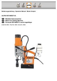
ALFRA ROTABEST Mini 40/2 HS Metallkernbohrmaschine Metal ...
ALFRA ROTABEST Mini 40/2 HS Metallkernbohrmaschine Metal ...
ALFRA ROTABEST Mini 40/2 HS Metallkernbohrmaschine Metal ...

Create successful ePaper yourself
Turn your PDF publications into a flip-book with our unique Google optimized e-Paper software.
<strong>ALFRA</strong> <strong>ROTABEST</strong> <strong>Mini</strong> <strong>40</strong>/2 <strong>HS</strong><br />
<strong><strong>Metal</strong>lkernbohrmaschine</strong><br />
<strong>Metal</strong> Core Drilling Machine<br />
Perceuse <strong>ROTABEST</strong> à socle magnétique<br />
Bedienungsanleitung<br />
Operation Manual<br />
Mode d’emploi<br />
18512 18513<br />
1
INHALTSVERZEICHNIS<br />
Seite 3 – 10 Bedienungsanleitung<br />
Seite 26 – 27 Zubehör<br />
Index<br />
Page 11 – 18 Operation Manual<br />
Page 26 – 27 Accessories<br />
Sommaire<br />
Page 19 – 25 Mode d’emploi<br />
Page 26 – 27 Accessoires<br />
2
Technische Daten<br />
Artikel – Nr.: 18512 // 18513<br />
Bezeichnung: <strong>ROTABEST</strong> <strong>Mini</strong> <strong>40</strong>/2 <strong>HS</strong><br />
Leistungsaufnahme: 1200 Watt<br />
Lastdrehzahl: 430/780 1 -min<br />
Werkzeugaufnahme: ¾“ (19 mm) Weldon<br />
Kühlmittelzufuhr: integriert, automatisch<br />
Spannung: (siehe Typenschild)<br />
Magnethaftkraft: 12000 N<br />
Bohr Ø max. in Stahl:<br />
- Kernbohrer <strong>40</strong> mm<br />
- Spiralbohrer 13 mm<br />
Schnitttiefe: 50 mm<br />
Hubbereich: 141 mm<br />
Magnetfußgröße: 95 x 200 mm<br />
3
Gerätebeschreibung<br />
A ) Antriebsmotor<br />
B ) Drehkreuz<br />
C ) Bedienfeld<br />
D) Magnetfuß<br />
E ) Weldon Aufnahme<br />
G ) Zylinderschraube für Hubbereichseinstellung des Antriebmotors<br />
J ) Aussparung für Sicherheitsgurt<br />
K ) Stellschrauben zum Justieren des Schlittens<br />
C ) Magnet Schalter D ) Motor Schalter<br />
4
Mitgeliefertes Zubehör<br />
• Transportkasten<br />
• Kühlmitteleinrichtung<br />
• Bohrspray<br />
• Schnellspannbohrfutter<br />
• Spänehaken<br />
• Sicherheitsgurt<br />
• <strong>HS</strong>S Co Kernbohrer Ø 22 mm<br />
• Auswerferstift 1935500<br />
• Inbusschlüssel 2,5 mm<br />
• Inbusschlüssel 6,0 mm<br />
Vor Inbetriebnahme:<br />
Bedienungsanleitung lesen<br />
Sicherheitshinweise beachten!<br />
Bestimmungsgemäße Verwendung<br />
Dieses Gerät ist bestimmt:<br />
In wettergeschützter Umgebung für den gewerblichen Einsatz in Industrie und<br />
Handwerk, zum Bohren von Materialien mit magnetisierbarer Oberfläche mit<br />
Kernbohrern, Vollbohrern und zum Schneiden von Gewinden.<br />
Das Gerät lässt sich waagrecht, senkrecht und über Kopf einsetzen.<br />
5
Sicherheitshinweise<br />
Verletzungsgefahr<br />
Bei Bohren an Wänden und Decken muss die <strong><strong>Metal</strong>lkernbohrmaschine</strong> durch<br />
den mitgelieferten Sicherheitsgurt (f) abgesichert werden. Die<br />
Magnethaftkraft bleibt bei einer Stromunterbrechung nicht erhalten.<br />
Der ausgebohrte Kern wird automatisch vom Auswerferstift (h) ausgestoßen.<br />
Unfallgefahr! Der Auswerferstift kann bei unsachgemäßer Handhabung<br />
brechen.<br />
Nur unbeschädigte Anschlussleitungen und Verlängerungsleitungen verwenden<br />
und regelmäßig auf Beschädigung überprüfen!<br />
Netzspannung und Spannungsangaben am Gerät müssen<br />
übereinstimmen.<br />
Persönliche Schutzausrüstung<br />
Beim Arbeiten mit diesem Gerät folgende Schutzausrüstung tragen:<br />
Schutzbrille, festes Schuhwerk, Gehörschutz, Haarnetz (bei langen Haaren),<br />
ggf. auch Schürze und Helm.<br />
Bedienhinweise<br />
Die Aufstellfläche für den Magnetfuß muss eben, sauber und rostfrei sein.<br />
Lack- und Spachtelschichten entfernen.<br />
Für die nicht magnetisierbaren Materialien verwenden Sie bitte die<br />
<strong>ROTABEST</strong> Vacubest Vakuumanlage (Artikel -Nr. 18150).<br />
Keine Elektro-Schweißarbeiten an dem Werkstück ausführen, auf dem die<br />
<strong><strong>Metal</strong>lkernbohrmaschine</strong> zum Einsatz kommt.<br />
Vor allen Arbeiten Kühlmitteleinrichtung (b) zur Unterstützung der Kühlung<br />
montieren.<br />
Durch Lösen der Inbusschraube (G) lässt sich der Antriebsmotor auf dem<br />
Schlitten stufenlos verstellen (für maximale Hubvergrößerung beim Einsatz mit<br />
Spiralbohrern, Bohrfuttern oder zum Gewindeschneiden).<br />
6
.<br />
Verletzungsgefahr! Gefahr eines elektrischen Schlages<br />
Bei Arbeiten an Wand und Decke empfehlen wir das Kühlen durch ein Spray<br />
(<strong>ALFRA</strong> BIO 2000, Artikel Nr. 21010).<br />
Ein- und Ausschalten.<br />
• Zuerst Kabel und Stecker auf Beschädigung prüfen!<br />
• Die Taste MAGNET ON betätigen, damit der Magnet haftet und der<br />
Halt des Bohrständers gewährleistet wird.<br />
• Bei Arbeiten an Wänden und Decken die Bohreinheit mit<br />
Sicherheitsgurt (f) sichern.<br />
• Antriebsmotor durch Betätigen der Taste MOTOR ON einschalten.<br />
Der Magnetfuß erhält jetzt die volle Magnethaftkraft! Ist dieser defekt,<br />
läuft der Motor nicht an!<br />
• Das Ausschalten erfolgt in umgekehrter Reihenfolge MOTOR OFF und<br />
dann MAGNET OFF!<br />
Werkzeug wechseln.<br />
Arbeiten mit Kernbohrer.<br />
• Auswerferstift (Zentrierstift) durch den Kernbohrerkopf schieben.<br />
• Kernbohrer mit Weldonschaft, werden mit den Klemmschrauben (DIN<br />
913) auf den beiden Spannflächen festgespannt.<br />
Kernbohrern mit RotaQuick Schaft, werden mit diesen<br />
Klemmschrauben (DIN 914) in einer Senkung festgespannt, den<br />
zweiten Gewindestift andrehen.<br />
7
Arbeiten mit Vollbohrer.<br />
• Das Bohrfutter mit Weldonschaft ( Art.Nr. 18107) ist nur zum Bohren<br />
mit Spiralbohrern bis Ø 10 mm geeignet.<br />
• Bohrfutter mit Adapter in die Bohrspindel einsetzen.<br />
• Spiralbohrer in Bohrfutter einsetzen fest spannen.<br />
Arbeitshinweise.<br />
Zuerst den Kernbohrer mit Zentrier- und Auswerferstift auf einen angekörnten<br />
Punkt oder Anriss ausrichten und aufsetzen. Das Bohren mit Alfra Rotabest<br />
Kernbohrern erfordert keinen großen Kraftaufwand. Den Kernbohrer aufsetzen<br />
und Werkstück anbohren, bis die ganze Schnittfläche als Kreisring ausgebildet<br />
ist.<br />
Während des Bohrvorgangs sollte der Kernbohrer ständig gekühlt werden.<br />
Optimale Kühlung ist durch unsere Kühlmitteleinrichtung (b) mittels<br />
Innenkühlung möglich.<br />
Während des Bohrens den Antriebsmotor nicht abschalten. Nach dem<br />
Bohrvorgang Kernbohrer bei laufendem Motor zurückziehen.<br />
Nach jedem Bohren Späne und Kern entfernen. – Verletzungsgefahr!<br />
8
Reinigen und Pflegen.<br />
Verletzungsgefahr durch unbeabsichtigtes Einschalten. Vor Pflegearbeiten<br />
Netzstecker ziehen.<br />
Motorraum von außen mit trockener Druckluft ausblasen.<br />
Anschlussleitungen auf Beschädigungen kontrollieren.<br />
Alle Gleitflächen regelmäßig reinigen und ölen. Sollte sich trotzdem durch<br />
Abnützung an der Schwalbenschwanzführung Seitenspiel einstellen, kann dies<br />
durch Nachstellen von seitlich angebrachten Gewindestiften (K) ausgeglichen<br />
werden.<br />
Nach ca. 250 Betriebsstunden sollten die Kohlebürsten ausgetauscht werden.<br />
Nach Arbeitsbeendigung empfehlen wir, die <strong><strong>Metal</strong>lkernbohrmaschine</strong> in dem<br />
Transportkoffer liegend aufzubewahren.<br />
Warten und Reparieren.<br />
Warten, prüfen und reparieren dürfen nur Elektrofachkräfte nach den im<br />
jeweiligen Land gültigen Vorschriften.<br />
Die <strong><strong>Metal</strong>lkernbohrmaschine</strong>n <strong>ALFRA</strong> <strong>ROTABEST</strong> sollten nach ca. 250<br />
Betriebsstunden von unserer <strong>ALFRA</strong> Werkstatt oder Vertragspartnern gewartet<br />
werden. Das Getriebeöl (Lubcon, Turmogearoil PE 150 300 ml) sollte ebenso<br />
wie die Kohlebürsten erneuert werden.<br />
Nur Original <strong>ALFRA</strong> Ersatzteile verwenden.<br />
Ersatzteilübersicht am Ende dieser Bedienungsanleitung.<br />
9
Garantie<br />
Für Alfra Rotabest <strong><strong>Metal</strong>lkernbohrmaschine</strong>n leisten wir Garantie gemäß den<br />
gesetzlichen und länderspezifischen Bestimmungen (Nachweis durch<br />
Rechnung).<br />
CE Konformität<br />
Wir erklären in alleiniger Verantwortung, dass dieses Produkt<br />
<strong>ALFRA</strong> <strong>ROTABEST</strong> <strong><strong>Metal</strong>lkernbohrmaschine</strong> <strong>Mini</strong> <strong>40</strong>/2 <strong>HS</strong><br />
mit den folgenden Normen und normativen Dokumenten übereinstimmt:<br />
Richtlinie 89/392/EWG, 91/368/EWG<br />
DIN EN 292 T.1 u. 2<br />
DIN EN 60204 T.1<br />
DIN VDE 07<strong>40</strong> T<br />
Der Nachweis der elektromagnetischen Verträglichkeit erfolgte<br />
entsprechend EG-Richtlinie 89/336/EWG nach folgenden Normen:<br />
EN 61000-3-2:1995/A1:1998/A2:1998<br />
EN 61000-3-3:1995<br />
EN 55014-1:1993/ A1:1997 55014-2:1997<br />
Bei einer nicht mit uns abgestimmten Änderung des Elektrowerkzeugs<br />
verliert diese Erklärung ihre Gültigkeit und die Gewährleistung erlischt.<br />
Der Schalldruckpegel am Arbeitsplatz kann 85 dp(A)<br />
überschreiten. In diesem Fall sind Schallschutzmaß-<br />
nahmen für den Bedienenden erforderlich.<br />
Gehörschutz tragen!<br />
10
Technical Data<br />
Prod. – No.: 18512 / 18513<br />
Name: Rotabest <strong>Mini</strong> <strong>40</strong>/2 <strong>HS</strong><br />
Input: 1200 Watt<br />
Load rpm: 430 /780 rpm<br />
Tool Holder : ¾“ (19 mm) Weldon<br />
Coolant supply: internal, automatically<br />
Voltage: (see nameplate)<br />
Magnetic Adhesion: 12000 N<br />
Boring Ø max. in Steel:<br />
- Core Cutters <strong>40</strong> mm<br />
- Twist Drills 13 mm<br />
Cutting Depth: 50 mm<br />
Stroke: 141 mm<br />
Size of Magnet Foot: 95 x 200 mm<br />
11
Description<br />
Description<br />
A ) Motor<br />
B ) Spindle<br />
C ) Control Panel<br />
D ) Magnet Foot<br />
E ) Weldon Arbor<br />
G ) Allan key for height adjusment on motor carriage slide<br />
J ) Recess for safety belt<br />
K ) Adjusting screws for adjusting the slide<br />
C ) Magnet Switch D ) Motor Switch<br />
12
Standard scope of supply<br />
• Transport Case<br />
• Coolant Unit<br />
• Safety Belt<br />
• Allan Key 2,5 mm<br />
• Allan Key 4,0 mm<br />
• Allan Key 6,0 mm<br />
Prior to use:<br />
Appropriate Use<br />
Read Operation Manual!<br />
Pay attention to Safety Precautions!<br />
This device is destined to:<br />
Cut material with magnetizable surface with core cutters, twist drills and to tap<br />
threads in sheltered environment for commercial use industry and craft. The<br />
device is suitable for drilling vertical, horizontal and overhead.<br />
Safety Precautions<br />
Danger of Injuries<br />
During drilling operations on walls and ceilings, the <strong>Metal</strong> Core Drilling<br />
Machine must be safeguarded with the included safety belt (f). The magnetic<br />
adhesion is not maintained in case of a failure of circuit.<br />
The cut core will be ejected automatically by the ejector pin (h). Danger of<br />
accident! The ejector pin could possibly break in case of improper use.<br />
13
Only use undamaged power and extension cords and regularly check on<br />
damages!<br />
Power supply and voltage details at the device must correspond.<br />
Personal protection equipment<br />
When working with this device, wear the following protection equipment:<br />
Safety goggles, appropriate footwear, ear protection, hair net (for long hair),<br />
possibly also apron and safety helmet.<br />
Precautions of use<br />
The place of installation for the magnet foot must be plane, clean and rust<br />
free. Remove lacquer- and filler.<br />
Do not execute any electric welding on the work piece, on which the <strong>Metal</strong><br />
Core Drilling Machine is used.<br />
Prior to all operations, mount coolant unit (b).<br />
Danger of injuries! Danger of an electric shock<br />
The motor can be continuously adjusted on the slide by releasing the Allan<br />
screw (for a maximum enlargement of the stroke, when using twist drills, drill<br />
chucks or when tapping).<br />
Danger of injuries! Danger of an electric shock<br />
For operations on walls and ceilings, we recommend cooling with our spray<br />
(<strong>ALFRA</strong> BIO 2000, Prod. - No. 21010).<br />
14
Switching on and off<br />
• Check connecting line and plug on damages first!<br />
• Push button MAGNET ON, in order to initiate the magnet and the<br />
magnetic adhesion is guaranteed.<br />
• When working on walls and ceilings, safe machine with safety belt (f).<br />
• Push the button MOTOR ON to start the Motor.<br />
• The magnet foot now reaches its maximum magnetic adhesion! In case<br />
of a damaged magnet, the motor won’t start.<br />
• To switch off machine proceed in reverse order: MOTOR OFF and then<br />
MAGNET OFF!<br />
Change of tools<br />
How to work with annular cutters.<br />
• Push ejector pin (center pin) through head of annular cutter.<br />
• Core drills with Weldon shank are tightened with clamping screws (DIN<br />
913) on both clamping surfaces.<br />
Core drills with RotaQuick shank are tightened with clamping screws<br />
(DIN 914) in a countersinking, tighten the second clamp screw.<br />
15
How to work with twist drills.<br />
• The drill chuck with Weldon shank (art. no. 18107) is only to be used for<br />
drilling with twist drills up to Ø 10 mm.<br />
• Insert drill chuck with adaptor in the Weldon arbor (E).<br />
• Insert twist drill in drill chuck and tighten.<br />
Operating tips<br />
First, place annular cutter with ejector pin on a marked center or marking.<br />
Drilling with <strong>ALFRA</strong> Rotabest cutters does not require much expenditure of<br />
force. Set the cutter and spot-drill, until the entire cut edge is formed as a<br />
circle.<br />
During the drilling process, the cutter should be cooled permanently. Optimal<br />
Cooling is possible by internal cooling with our coolant unit.<br />
During the drilling process, do not stop the motor. After the process, cutter<br />
draws back with running motor.<br />
Remove chips and core after each drilling. Remove chips with Chip-Remover<br />
– do not touch with bare hands – DANGER OF INJURY!<br />
16
Cleaning<br />
Danger of injuries by unintentional switching on. Pull plug prior to cleaning.<br />
Clean motor by means of dry compressed air (from the outside).<br />
Check connecting lines on damages.<br />
Clean and grease sliding surfaces regularly. Should, nevertheless, lateral play<br />
arise by wear of the dovetail guide, this could be adjusted by adjusting the<br />
laterally positioned set screws (K).<br />
Carbon brushes should be replaced after app. 250 hours running time.<br />
After the work is finished, we recommend to store the <strong>Metal</strong> Core Drilling<br />
Machine in the transport case in a lying position.<br />
Maintenance and repair<br />
Maintenance, check and repairs are only to be made by electronics<br />
specialists according to the valid regulations of the respective country.<br />
The <strong>Metal</strong> Core Drilling Machine <strong>ALFRA</strong> <strong>ROTABEST</strong> should be serviced<br />
after app. 250 hours running time by our <strong>ALFRA</strong> workshop or appointed<br />
dealers. The Gear oil (Lubcon, Turmogearoil PE 150 300ml) should be<br />
exchanged as well as the brushes.<br />
Only use genuine <strong>ALFRA</strong> spare parts.<br />
Spare part list at the end of this operation manual.<br />
Guarantee<br />
For our <strong>ALFRA</strong> <strong>ROTABEST</strong> <strong>Metal</strong> Core Drilling Machines we grant guarantee<br />
according to the legal and regional regulations (proven by invoice).<br />
17
CE Declaration of Conformity<br />
We declare in our exclusive responsibility, that this product corresponds to the<br />
following standards and specifications:<br />
Specification 89/392/EWG, 91/368/EWG<br />
DIN EN 292 part 1 and 2<br />
DIN EN 60204 part 1<br />
DIN VDE 07<strong>40</strong> T<br />
The proof of an electromagnetic amicability took place according the<br />
appropriate EC-Specification 89/336/EWG after the following norms:<br />
EN 61000-3-2:1995/A1:1998/A2:1998<br />
EN 61000-3-3:1995<br />
EN 55014-1:1993/ A1:1997 55014-2:1997<br />
If the electric tool is modified without our authorization, this declaration will<br />
lose its validity and the guarantee expires.<br />
The sound pressure level at the work place might exceed 85 dp(A). In case the<br />
user must wear hearing protectors.<br />
18
Détails techniques<br />
Nro. d’article: 18512/18513<br />
Description: Rotabest <strong>Mini</strong> <strong>40</strong>/2<strong>HS</strong><br />
Puissance: 1200 watts<br />
Vitesse sous charge: 430 / 780 1 -min<br />
Raccordement d’outil: ¾“ (19 mm) Weldon<br />
Alimentation en lubrifiant: automatique, intégrée dans le système<br />
Tension d’alimentation: se référer à la plaque de fabrication<br />
Adhérence magnétique : 12000 N<br />
Diamètre de perçage maximum dans l’acier<br />
- fraises à carotter <strong>40</strong> mm<br />
- foret hélicoïdal 13 mm<br />
Profondeur de coupe : 50 mm<br />
Course : 141 mm<br />
Dimensions du<br />
socle magnétique: 95 x 200 mm<br />
19
Description de l’appareil<br />
A ) moteur de commande<br />
B ) tourniquet<br />
C ) tableau de commande<br />
D ) socle magnétique<br />
E ) Tige Weldon<br />
F ) graduation de profondeur<br />
G ) vis de réglage de course du moteur<br />
J ) passe pour la courroie de sécurité<br />
K ) vis d’ajustage du glissoir<br />
C ) Interrupteur du socle magnétique D ) Interrupteur du moteur<br />
20
Accessoires fournis avec l’appareil<br />
• malette de transport<br />
• dispositif de lubrification<br />
• aérosol de lubrifiant<br />
• mandrin de serrage rapide<br />
• crochet pour retirer les copeaux<br />
• courroie de sécurité<br />
• fraise <strong>HS</strong>S Co - Ø 22 mm<br />
• tige d’éjection<br />
• clé pour vis à 6 pans creux 2.5 mm<br />
• clé pour vis à 6 pans creux 6.0 mm<br />
Avant la mise en marche:<br />
lire absolument la notice d’emploi!<br />
respecter les consignes de sécurité!<br />
Conditions d’utilisation<br />
Cet appareil est conçu pour des travaux de caractère industriel ou artisanal<br />
dans un endroit protégé des intempéries pour percer des trous dans des<br />
matériaux dont la surface est magnétisable avec des fraises à carotter et des<br />
forets et pour procéder à des opérations de filetage.<br />
Il peut être utilisé horizontalement, verticalement ou à bras levés.<br />
21
Conseils de sécurité<br />
La surface où le socle magnétique sera posé doit être plane, propre et sans<br />
rouille. Éliminez les couches de peinture ou de mastic auparavant.<br />
Ne faites en aucun cas des travaux d’électro-soudure sur l’élément sur lequel<br />
la perceuse sera employée.<br />
Avant tous travaux, fixer le dispositif de lubrification pour que le<br />
refroidissement soit assuré.<br />
En désserrant la vis à 6 pans creux on peut monter ou descendre le<br />
moteur à volonté pour atteindre une course maximum, en particulier<br />
lors de l’emploi d’un foret hélicoïdal, d’un mandrin ou d’une opération<br />
de taraudage.<br />
Danger d’accident et d’électrolution !<br />
22
Instructions d’utilisation<br />
La surface de l’élément où repose le socle magnétique doit être plane, propre,<br />
sans rouille. Eliminez auparavant toutes couches de peinture ou de mastic. Si<br />
vous travaillez des matériaux non magnétisables, utilisez notre système à vide<br />
<strong>ROTABEST</strong> Vacubest (nro. d’article 18150).<br />
N’effectuez en aucun cas des travaux d’électro-soudure sur l’élément sur<br />
lequel la perceuse sera employée.<br />
Avant tous travaux fixer le dispositif de lubrification pour que le refroidissement<br />
soit assuré.<br />
En déserrant la vis à 6 pans creux le moteur peut être déplacé sur le glissoir à<br />
volonté en cas d’un besoin de course maximum, si des forets hélicoïdaux ou<br />
un mandrin sont employés ou si des travaux de taraudage sont nécessaires.<br />
Danger d’accident ! Danger d’électrocution !<br />
Pour des travaux sur murs ou plafonds nous conseillons le refroidissement<br />
avec un aérosol de lubrifiant (<strong>ALFRA</strong> BIO 2000 – nro. d’article 21010).<br />
Mise en marche et arrêt de la perceuse<br />
• Assurez vous du bon état des fiches, prises et fils électriques.<br />
• Appuyez sur la touche MAGNET (Aimant) pour que le socle<br />
magnétique adhère et que la stabilité de l’appareil soit garantie.<br />
• Pour des travaux sur murs et plafonds, attachez la perceuse avec la<br />
courroie de sécurité.<br />
• Mettre le moteur en marche avec la touche MOTOR ON.<br />
• La mise an arrêt se fait alors dans le sens contraire, c’est-à-dire d’abord<br />
MOTOR OFF puis MAGNET OFF.<br />
Changement d’outils<br />
Pour des travaux avec des fraises à tige Weldon<br />
23
• Placer la tige d’éjection (ou pointeau de centrage) dans la tête de la<br />
fraise.<br />
• Les fraises à tige Weldon sont fixées avec les vis (DIN 913) sur les<br />
deux surfaces prévues à cet effet.<br />
Les fraises à tige RotaQuick sont fixées avec des vis (DIN 914)<br />
dans l’encoche prévue, serrer la seconde vis sans tête.<br />
Pour des travaux avec des forets hélicoïdaux<br />
• Le mandrin de changement rapide (nro. d’article 18107) est utilisé<br />
uniquement pour les opérations de perçage avec des forets hélicoïdaux<br />
d’un diamètre max. de 10 mm.<br />
• Ajuster le mandrin avec l’adaptateur dans la broche<br />
• Insérer le foret hélicoïdal dans le mandrin et le verrouiller.<br />
Conseils d’opération<br />
Tout d’abord placer la fraise avec la pointe de centrage et la tige d’éjection sur<br />
un point déjà amorcé au pointeau ou fissuré. Le perçage avec les fraises Alfra<br />
24
Rotabest ne demande pas d’efforts particuliers. Placer la fraise et percer la<br />
pièce de travail jusqu’à ce que toute la surface à couper soit amorcée.<br />
Pendant le perçage la fraise doit être continuellement refroidie. Un<br />
refroidissement optimal est assuré avec le dispositif de lubrification (b) par<br />
refroidissement intérieur.<br />
Ne pas arrêter le moteur pendant le perçage. Une fois le perçage terminé,<br />
retirez la fraise pendant que le moteur est encore en marche.<br />
Après chaque opération de perçage, retirer le noyau et les copeaux.<br />
Ne jamais essayer de les enlever avec les doigts - Danger de blessure !<br />
Nettoyage et entretien<br />
Attention ! Débranchez l’appareil avant tout nettoyage de l’appareil !<br />
Dépoussiérer la partie extérieure du moteur à l’air comprimé.<br />
Contrôler l’état du fil d’alimentation électrique.<br />
Nettoyez et lubrifiez régulièrement les surfaces lisses. Si par l’usure on observe<br />
un certain jeu latéral, on peut y remédier en ajustant les vis sans tête (K) situées<br />
sur le coté.<br />
Les charbons doivent être changés après environ 250 heures d’emploi de la<br />
machine.<br />
Nous recommandons de stocker la perceuse dans la malette de transport en<br />
position horizontale après l’emploi.<br />
25
Révision et réparation<br />
Garantie<br />
Seuls les spécialistes sont aptes à contrôler, réviser ou réparer ces<br />
appareils...des réparations impropres peuvent causer des dommages et<br />
dangers considérables pour leurs utilisateurs.<br />
Après environ 250 heures de travail les perceuses <strong>ALFRA</strong> <strong>ROTABEST</strong><br />
doivent être révisées à l’atelier <strong>ALFRA</strong> ou par un atelier agréé par<br />
<strong>ALFRA</strong>. L'huile de boîte de vitesse (Lubcon, Turmogearoil PE 150 300 ml)<br />
ainsi que les charbons devraient être renouvelés.<br />
‘Employer exclusivement les pièces de rechange de la marque <strong>ALFRA</strong>.<br />
Les conditions de garantie sont en concordance avec les directives légales<br />
appliquées en Allemagne (la facture sert de preuve).<br />
Déclaration de Conformité aux Normes CE<br />
Nous déclarons sous notre entière responsabilité que ce produit correspond<br />
aux normes et directives suivantes :<br />
Recommandation 89/392/EWG, 91/368/EWG<br />
DIN EN 292 T.1 et 2<br />
DIN EN 60204 T.1<br />
DIN VDE 07<strong>40</strong>T<br />
Preuve de compatibilité électro-magnétique : d’après les directives<br />
89/336/EWG et selon les normes :<br />
EN 61000-3-2:1995/A1:1998/A2:1998<br />
EN61000-3.3:1995<br />
EN55014-1:1993/A1:1997 55014-2:1997<br />
Si la machine électrique subit des modifications sans notre<br />
autorisation explicite, cette déclaration perd sa validité et la garantie<br />
expire immédiatement.<br />
Le niveau de pression acoustique au poste de travail peut dépasser 85dB(A) :<br />
il est donc nécessaire que l’utilisateur porte une protection acoustique.<br />
26
Zubehör / Accessories / Accessories<br />
<strong>ALFRA</strong> <strong>ROTABEST</strong> <strong>HS</strong>S Co Kernbohrer<br />
Ø 12 – <strong>40</strong> mm Schnitttiefe 25 mm<br />
Artikel - Nr. 1901 0.. 025 und 1902 0.. 025<br />
Zentrier- und Auswerferstift<br />
Artikel - Nr. 1926500<br />
<strong>ALFRA</strong> Rota Quick <strong>HS</strong>S Co Kernbohrer<br />
Ø 12 – <strong>40</strong> mm Schnitttiefe 35 mm<br />
Artikel - Nr. 1901 0.. 035<br />
Zentrier- und Auswerferstift<br />
Artikel - Nr. 1935500<br />
<strong>ALFRA</strong> Rota Quick <strong>HS</strong>S Co Kernbohrer<br />
Ø 12 – <strong>40</strong> mm Schnitttiefe 50 mm<br />
Artikel - Nr. 1901 0.. 050 und 1902...050<br />
Zentrier- und Auswerferstift<br />
Artikel - Nr. 1950500<br />
<strong>ALFRA</strong> Rota Quick HM Kernbohrer<br />
Ø 14 – 35 mm Schnitttiefe 35 mm<br />
Artikel - Nr. 2003 0.. 035<br />
Zentrier- und Auswerferstift<br />
Artikel-Nr. 2001500<br />
<strong>ALFRA</strong> Rota Quick HM Kernbohrer<br />
Ø 14 – <strong>40</strong> mm Schnitttiefe 50 mm<br />
Artikel - Nr. 2003 0.. 050<br />
Zentrier- und Auswerferstift<br />
Artikel - Nr. 2001501<br />
<strong>HS</strong>S Kegel- und Entgratsenker<br />
Ø 25 mm Artikel - Nr. 18533<br />
Ø 30 mm Artikel - Nr. 18536<br />
Ø <strong>40</strong> mm Artikel - Nr. 18534<br />
Ø 55 mm Artikel - Nr. 18537<br />
Bohrfutter Ø 1-13 mm<br />
Artikel - Nr. 18107<br />
27<br />
<strong>ALFRA</strong> Rota Quick <strong>HS</strong>S Co Core Cutter<br />
Ø 12 – <strong>40</strong> mm Cutting depth 25 mm<br />
Product -No. 1901 0.. 025 / 1902 0.. 025<br />
Center- and ejector pin<br />
Product –No. 1926500<br />
<strong>ALFRA</strong> Rota Quick <strong>HS</strong>S Co Core Cutter<br />
Ø 12 – <strong>40</strong> mm Cutting depth 35 mm<br />
Product -No. 1901 0.. 035<br />
Center- and ejector pin<br />
Product –No. 1935500<br />
<strong>ALFRA</strong> Rota Quick <strong>HS</strong>S Co Core Cutter<br />
Ø 12 – <strong>40</strong> mm Cutting depth 50 mm<br />
Product -No. 1901 0.. 050 / 1902 0.. 050<br />
Center- and ejector pin<br />
Product –No. 1950500<br />
<strong>ALFRA</strong> Rota Quick TCT Core Cutter<br />
Ø 14 – 35 mm Cutting Depth 35 mm<br />
Product -No. 2003 0.. 035<br />
Center- and ejector pin<br />
Product –No. 2001500<br />
<strong>ALFRA</strong> Rota Quick TCT Core Cutter<br />
Ø 14 – <strong>40</strong> mm Cutting Depth 50 mm<br />
Product -No. 2003 0.. 050<br />
Center- and ejector pin<br />
Product –No. 2001501<br />
<strong>HS</strong>S Countersink and Deburrer<br />
Ø 25 mm Product No. 18533<br />
Ø 30 mm Product No. 18536<br />
Ø <strong>40</strong> mm Product No 18534<br />
Ø 55 mm Product No 18537<br />
Drill Chuck Ø 1-13 mm<br />
Product -No. 18107<br />
Fraises à carotter <strong>ALFRA</strong> <strong>ROTABEST</strong> <strong>HS</strong>S-Co<br />
Ø 12 – <strong>40</strong> mm Profondeur de coupe 25 mm<br />
Nro. d’article 1901 0.. 025 und 1902 0.. 025<br />
Pointeau de centrage et tige d’éjection<br />
Nro. d’article 1926500<br />
Fraises à carotter <strong>ALFRA</strong> Rota-Quick <strong>HS</strong>S-Co<br />
Ø 12 – <strong>40</strong> mm Profondeur de coupe 35 mm<br />
Nro. d’article 1901 0.. 035<br />
Pointeau de centrage et tige d’éjection<br />
Nro. d’article 1935500<br />
Fraises à carotter <strong>ALFRA</strong> Rota-Quick <strong>HS</strong>S-Co<br />
Ø 12 – <strong>40</strong> mm Profondeur de coupe 50 mm<br />
Nro. d’article1901 0.. 050 und 1902...050<br />
Pointeau de centrage et tige d’éjection<br />
Nro. d’article 1950500<br />
Fraises à carotter en carbure <strong>ALFRA</strong> Rota-<br />
Quick<br />
Ø 14 – 35 mm Profondeur de coupe 35 mm<br />
Nro. d’article 2003 0.. 035<br />
Pointeau de centrage et tige d’éjection<br />
Nro. d’article 2001500<br />
Fraises à carotter en carbure <strong>ALFRA</strong> Rota-<br />
Quick<br />
Ø 14 – <strong>40</strong> mm Profondeur de coupe 50 mm<br />
Nro. d’article 2003 0.. 050<br />
Pointeau de centrage et tige d’éjection<br />
Nro. d’article 2001501<br />
Fraises à ébavurer <strong>HS</strong>S<br />
Ø 25 mm Nro. d’article 18533<br />
Ø 30 mm Nro. d’article 18536<br />
Ø <strong>40</strong> mm Nro. d’article 18534<br />
Ø 55 mm Nro. d’article 18537<br />
Mandrin de serrage rapide Ø 1 - 13 mm<br />
Article 18107
<strong>ALFRA</strong> Gewindeschneidapparat M3 – M12<br />
Artikel – Nr. 18652<br />
<strong>ALFRA</strong> Gewindeschneidapparat M10 – M 20<br />
Artikel – Nr. 18653<br />
Mechanische Rohr-Fixiereinrichtung<br />
Artikel - Nr. 18019<br />
Vakuumanlage Vacubest<br />
Artikel - Nr. 18150<br />
Kühlmitteleinrichtung<br />
Artikel - Nr. 18104<br />
<strong>ALFRA</strong> Bio 2000 Schneid- und Bohrspray<br />
Artikel - Nr. 21010<br />
<strong>ALFRA</strong> Magnet Späneheber<br />
Artikel-Nr. 18654<br />
28<br />
<strong>ALFRA</strong> Tapping Attachment M3 – M12<br />
Product-No. 18652<br />
<strong>ALFRA</strong> Tapping Attachment M10 – M 20<br />
Product-No. 18653<br />
Attachment for clamping pipes<br />
Product -No. 18019<br />
Vacuum device Vacubest<br />
Product -No. 18150<br />
Coolant unit<br />
Product -No. 18104<br />
<strong>ALFRA</strong> Bio 2000 Cutting Oil<br />
Product -No. 21010<br />
<strong>ALFRA</strong> Magnetic Chip Remover<br />
Product -No. 18654<br />
Dispositif de taraudage M3 - M12<br />
Article 18652<br />
Dispositif de taraudage M10 – M20<br />
Article 18653<br />
Elément de Fixation mécanique sur tuyau<br />
Nro. d’article 18019<br />
Système à vide Vacubest<br />
Nro. d’article 18150<br />
Dispositif de lubrification<br />
Nro. d’article 18104<br />
Aérosol de lubrifiant de coupe et de perçage<br />
<strong>ALFRA</strong> Bio 2000<br />
Nro. d’article 21010<br />
Outil magnétique de nettoyage <strong>ALFRA</strong><br />
Nro. d’article 18654
Ersatzteile / Spare Parts / Pièces de rechange<br />
Pos. Stck. Art.-Nr.<br />
1 1 189501050 Ständergehäuse housing chassis<br />
2 1 189501080 Schlitten slide glissoir<br />
3 1 189501003 Zahnstange rack crémaillère<br />
4 1 189501052 Mess.Führungsschiene rechts brass guide rail, right side lardon de glissière, côté droit<br />
5 1 189501053 Mess.Führungsschiene links brass guide rail, left side lardon de glissière, côté gauche<br />
29
6 1 189030512A Gewindestift DIN 915 M5x12 set screw DIN 915 vis filetée sans tête<br />
7 1 189020512 Zylinderschrauben DIN 6912 5x12 hexagon socket screw vis à tête<br />
8 12 189020512 Zylinderschrauben DIN 6912 5x12 hexagon socket screw vis à tête<br />
11 1 189100019 Sicherungsscheibe 19 mm lock washer clip d'arrêt<br />
12 2 189112535 Passcheiben washer rondelle<br />
13 1 189501056 Ritzelwelle pinion shaft arbre de pignon<br />
14 2 189490502 Gleitlager plain bearing palier lisse<br />
15<br />
17 3 189501060 Speichen kpl. spoke moyeux<br />
19 5 1890<strong>40</strong>510 Gewindestifte DIN 913 M5x10 set screw DIN 913 M5x10 vis filetée sans tête M5 x 10<br />
20 1 189411020 Magnetfuss magnet foot socle magnétique<br />
21 1 1890106<strong>40</strong> Zylinderschrauben M6x<strong>40</strong> DIN 912 hexagon socket screw M6x<strong>40</strong> vis à tête M6x<strong>40</strong><br />
22 3 189010645 Zylinderschrauben M6x45 DIN 912 hexagon socket screw M6x45 vis à tête M6x45<br />
24 4 1891<strong>40</strong>416 Gewindeschrauben M4x16 schoulder bolt M4x16 vis filetée M4 X 16<br />
25 1 189491003<br />
25 189491005<br />
Steuerkasten kpl. mit Leiter-<br />
platte und Schaltelement 230 Volt<br />
Steuerkasten kpl. mit Leiter-<br />
platte und Schaltelement 110 Volt<br />
30<br />
control case with printed circuit<br />
board and key pad 230 Volt<br />
control case with printed circuit<br />
board and key pad 110 Volt<br />
boîtier de commande + carte<br />
électronique + circuit logique de<br />
230 volts.<br />
boîtier de commande + carte<br />
électronique + circuit logique de<br />
110 volts.<br />
(26) 189411075 Leiterplatte 110 Volt printed circuit board 110 Volt carte électronique 110 V<br />
(26) 189411070 Leiterplatte 230 Volt printed circuit board 230 Volt carte électronique 230 V<br />
27 2 189501062 Erdungsschraube earthing screw vis de mise à la terre<br />
30 1 189010880 Inbusschrauben DIN 912 M8x80 hexagon socket screw vis à tête DIN 912 M8x80<br />
31 1 189501076 Befestigungsstein motor fixing part fixation pour le moteur<br />
32 1 189490605 Verschraubung gerade threaded joint presse-étoupe<br />
33 1 189501033 Elast. Kabelführung flexible cable guiding gaine cannelée<br />
34 1 189490603 Verschraubung gerade threaded joint presse-étoupe<br />
35 1 189501035 Satz Litze set of flexible cord fil torsadé<br />
36 1 189490602 Knickschutz protection sleeve fils d'allimentation moteur<br />
37 1 189480276 Anschlussleitung supply cable 230 V câble et prise 230 V<br />
38 1 189302043 Einschraubtülle 1/8" screw in spout 1/8" douille filetée 1/8"<br />
<strong>40</strong> 4 189184816 Blechschrauben 4,8 x 16 tapping screw 4,8 x 16 mm vis 4,8 x 16 mm<br />
41 1 189501077 Flanschstück EHN 20 flange piece EHN 20 raccord à bride EHN20<br />
42 1 18110 Motor AHN 20/3 230 V Motor AHN 20/3 230 V moteur AHN 20/3 230 V<br />
18110.110 Motor AHN 20/3 110 V Motor AHN 20/3 110 V moteur AHN 20/3 110<br />
43 3 189621036 Gewindestift M8x8 set screw Vis HC<br />
44 1 189301091 Anschlag stop butée<br />
45 2 1891<strong>40</strong>616 Gewindeschraube DIN 7991 6x16 screw vis<br />
25 1 189411055 PVC Gehäuse Case chassis C.P.V.<br />
46 1 189411056 Magnetschalter magnet switch Interrupteur du socle magnétique<br />
47 1 189411057.110 Motorschalter 110 Volt motor switch 110Volt interrupteur de moteur 110 volts<br />
47 1 189411057 Motorschalter 230 Volt motor switch 230Volt interrupteur de moteur 230 volts<br />
48 1 189411058 Brückengleichrichter bis <strong>40</strong>0 Volt bridge rectifier to <strong>40</strong>0 V redresseur de pont jusqu'à <strong>40</strong>0 V<br />
48 1 189411058.110 Brückengleichrichter bis 200 Volt bridge rectifier to 200 V redresseur de pont jusqu'à 200 V
Pos. Art.Nr. Menge<br />
1 189502070 1 Motorkappe cap for motor housing Couvercle du moteur<br />
2 189622018 4 Blechschraube HC 4,8x45 screw 4,8 x 45 Vis à tôle 4,8 x 45<br />
3 189502085 1 Anker 230 V armature, compl. 230 V Induit compl. 230 V<br />
3 189502085.110 1 Anker 110 V armature, compl. 110 V Induit compl. 110 V<br />
4 189812011 1 Rillenkugellager 608 2Z deep groove ball bearing 608.2Z Roulement à bille 608. 2Z<br />
5 189601017 1 Sicherungsring 28/1,2 retaining ring Circlip extérieur<br />
6 189502053 2 Kohlebürstenhalter carbon brush holder Support due charbon<br />
7 189502054 2 Kohlebürsten carbon brush Charbon<br />
8 189622009 4 Federscheibe B4 gewellt spring discs Rondelle à ressort<br />
9 189622010 4 Gewindefurchschraube CM4x12 screws Vis taraudeuse<br />
10 189502087 1 Wellendichtring KEIV 15x21x3 rotary shaft seal Joint à lèvre avec ressort<br />
31
11 189502011 1 Steckkerbstift 4x12 dowel pin Goupille cannelée<br />
12 189502057 1 O-Ring 22x2,5 o-ring Joint torique<br />
13 189502073 4 Blechschraube HC 4,8x60 screw Vis à tôle<br />
14 189601098 1 Rillenkugellager 6001 2RS deep groove ball bearing 6001.2RS Roulement à bille 6001.2RS<br />
15 189502058 1 Getriebelagerschild gear box flange Couvre-engrenage<br />
16 189502089 1 Getriebegehäuse gear box Boite de vitesse<br />
17 189502017 1 Zwischenrad 44 Z intermediate gear 44 T Pignon à 44 D<br />
18 189502090 1 Welle mit 2 Ritzeln 11/17 shaft with two gears 11/17 Arbre avec deux pignon 11/17<br />
19 189502091 1 Dichthülse bushing douille d'étancheité<br />
20 189502092 1 Seeger-Sprengring SW 10 CIRCLIP Circlip extérieur<br />
21 189502021 1 Rillenkugellager 6203 2RS deep groove ball bearing 6203.2RS Roulement à bille 6203.2RS<br />
22 189302043 1 Einschraubtülle 1/8" screw in spout 1/8" douille filetée 1/8"<br />
23 189502023 1 Wellendichtring shaft sealing ring Joint à lèvres avec ressort<br />
24 189502059 1 Arbeitsspindel motor spindle Broche<br />
25 189502025 1 Staubkappe dust cap chapeau contre poudre<br />
26 189621035 1 Druckfeder 1,6x15x105 pressure spring Ressort de rappel<br />
27 189621038 1 Federhalterung spring attachment Butée<br />
28 189621037 1 Sicherungsring JK 19 retaining ring Circlip extérieur<br />
29 189621036 2 Gewindestift M8x8 set screw Vis HC<br />
30 189502030 1 Nadel-Axial-Kugellager needle bearing Palier de butée<br />
31 189502031 1 Radialwellendichtring shaft sealing ring Joint à lèvres avec ressort<br />
32 189502039 1 Spindelrad <strong>40</strong> Z spindle gear <strong>40</strong> T Pignon <strong>40</strong> D<br />
33 189502033 1 Paßfeder A5x5x12 feather key Clavette parallèle<br />
34 189502034 1 Paßscheibe 15/22x0,2 washer Rondelle<br />
35 189502035 1 Sicherungsring 15/1 retaining ring Circlip extérieur<br />
36 1895020<strong>40</strong> 1 Welle f. Zahnradblock 18 Z shaft for gear block 18 T Arbre avec pignon 18 D<br />
37 189502037 1 Rillenkugellager 608 deep groove ball bearing 608 Roulement à bille 608<br />
38 189502095 1 Zahnradblock 34/<strong>40</strong> Z gear block 34/<strong>40</strong> T Pignons 34 / <strong>40</strong> D<br />
39 189622055 1 Paßfeder A5x5x28<br />
Nadelhülse<br />
feather key Clavette parallèle<br />
<strong>40</strong> 189601020 2 HK0810 needle bearing Roulement à aiguilles<br />
41<br />
42 189502042 1 Luftleitring fan shroud Carter du ventilateur<br />
43 189502043 2 Blechschrauben 3,9 x 60 screw 3,9 x 60 Vis à tôle 3,9 x 60<br />
44 189502055 1 Feld 230 V field, compl. 230 V Stator complet 230 V<br />
44 189502055.110 1 Feld, kpl. 110 Volt field, compl. 110 V Stator complet 110 V<br />
45 189502076 1 Motorgehäuse kpl. motor housing, compl. Carcasse de moteur<br />
46 189621033 1 Paßscheibe 13/19x0,5 washer Rondelle<br />
47 189502064 1 Dichtring sealing ring Joint torique<br />
48 189502065 1 Entstörkondensator interference capacitor Condensateur d'antiparasitage<br />
49 189502096 1 O-Ring 85x1,78 o-ring Joint torique<br />
50 189502097 1 Schaltknopf gear shift knob interrupteur de commande<br />
51 189302045 1 Dichtring 1/8" sealing ring Joint torique<br />
52 189302044 1 Schlauchkupplung hose coupling raccordement de flexible<br />
53 189502098 1 Sicherungsring 26/1,2 retaining ring Circlip extérieur<br />
54 189502101 1 Rastbolzen locking pin boulon d'arrêt<br />
55 189502099 1 Zylinderstift 3m6x10 pin cheville cylindrique<br />
56 189502100 1 Schaltbolzen control pin boulon de mise au point<br />
32