radiocomando digitale a codici rolling s449 - Cardin Elettronica
radiocomando digitale a codici rolling s449 - Cardin Elettronica
radiocomando digitale a codici rolling s449 - Cardin Elettronica

You also want an ePaper? Increase the reach of your titles
YUMPU automatically turns print PDFs into web optimized ePapers that Google loves.
CARDIN ELETTRONICA spa<br />
Via Raffaello, 36- 31020 San Vendemiano (TV) Italy<br />
Tel: +39/0438.404011-401818<br />
Fax: +39/0438.401831<br />
email (Italy):<br />
Sales.office.it@cardin.it<br />
email (Europe):<br />
Sales.office@cardin.it<br />
Http:<br />
www.cardin.it<br />
Attention! Only for EU customers - WEEE marking.<br />
This symbol indicates that once the products life-span has expired it must be disposed of separately<br />
from other rubbish. The user is therefore obliged to either take the product to a suitable differential<br />
collection site for electronic and electrical goods or to send it back to the manufacturer if the intention<br />
is to replace it with a new equivalent version of the same product.<br />
Suitable differential collection, environmental friendly treatment and disposal contributes to avoiding negative effects on<br />
the ambient and consequently health as well as favouring the recycling of materials. Illicitly disposing of this product by<br />
the owner is punishable by law and will be dealt with according to the laws and standards of the individual member nation.<br />
Description<br />
The S449 Radio control system in "FM" consists of one or more transmitters and one or more receivers which can be<br />
combined to meet the specific needs of the system. As the system use dynamic codes each code is managed individually<br />
by the receiver.<br />
Important: The transmitted code changes for each command (<strong>rolling</strong> code). If disturbance interrupts the transmission,<br />
the receiver will wait for a different code, the relay can then only be activated by first releasing and then pressing the<br />
transmitter channel button again.<br />
Use<br />
The S449 radio control allows the remote activation of electrical and electronic appliances with its best use in the following<br />
areas: automatic opening systems, alarm systems and multiple access systems (apartment blocks etc.) and in all systems<br />
which require remote control activation (without wires) using secret codes.<br />
The receiver has been designed for multiple access with UP to 1000 each of which may be memorised or cancelled individually.<br />
Each code is stored in a memory location chosen on the display and the location can activate UP to 4 functions.<br />
1 transmitter = 4 functions max. = 1 location; 1000 users = 4000 functions max.<br />
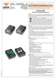
Transmitter versions<br />
TRQ449100 Miniaturized transmitters 1 button<br />
TRQ449200 Miniaturized transmitters 2 buttons<br />
TRQ449300 Miniaturized transmitters 3 buttons<br />
TRQ449400 Miniaturized transmitters 4 buttons<br />
TRQ44940M Wall mounted transmitters 4 buttons<br />
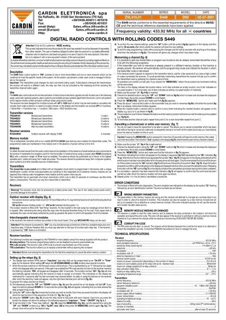
Receiver versions<br />
RCQ449D00 Outdoor receiver with display (1000) 4 channels<br />
Memory module<br />
This is extractable, furnished with a non volatile EEPROM 24C64 type memory and contains the transmitter codes. The<br />
programmed codes are maintained in this module even in the absence of power without a time limit.<br />
Antenna<br />
To obtain the best results from the radio control device the installation of the antenna is fundamental as once connected to<br />
the receiver it represents the reception point for the transmitter. A tuned antenna using a coaxial cable RG58 (impedance<br />
50Ω) with a maximum length of 15 m must be installed. The antenna should be positioned out of doors in the highest<br />
possible point, visible and away from metal structures. The receiver should be positioned away from computer systems,<br />
alarm systems and other possible sources of disturbance.<br />
Transmitters<br />
The transmitter is pre-coded and is fitted with an integrated circuit which is programmed in the factory with a unique<br />
identification number. All the code parameters are contained in this integrated circuit (external memory modules are not<br />
required) thus making code management more reliable and the system more secure.<br />
The transmitter has an automatic shut down mechanism which cuts in after 25 seconds of continuous use (this limits<br />
battery consumption). This time can vary from transmitter to transmitter.<br />
Receivers<br />
Warning! The receivers must only be powered by a safety power pack. The use of non safety power packs could<br />
provoke damage to the system.<br />
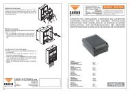
Outdoor receiver with display (fig. 4)<br />
- The outdoor receiver card (printed circuit CS1127a) is fitted with an 14-way terminal board and has the following electrical<br />
connections:<br />
12V ac/dc between binding posts 1-2 - 24V ac/dc between binding posts 1-3.<br />
The outdoor receiver is fitted with "fast-fitting" brackets. Fix the bracket to the wall using two rawlplugs (check that it is<br />
in square). After connecting the wiring slide the case onto the bracket therefore fixing it to the wall. If any repair work is<br />
necessary the case can be easily extracted by pushing upwards the action of which will separate it from the bracket.<br />
Interchangeable channel modules<br />
In the receivers the channel functions are printed on the circuit board. Only type MCC4491R0 relays can be used.<br />
Attention! If the receiver is powered by "24V" you may simultaneously activate two of the four available relays plus one<br />
impulsive relay. It follows therefore that you must pay attention to the type of function each relay has. If the receiver<br />
is powered by "12V" there is no limitation.<br />
Receiver functions<br />
The following functions are managed by the PGM449 for more details consult the manual supplied with the product.<br />
Blocking buttons: The receiver programming buttons can be disabled to prevent unauthorised use.<br />
PIN code security: This function uses a PIN code to prevent unauthorised use of the receiver.<br />
TRS substitution: This function allows you to replace a transmitter without opening the container<br />
Attention! Before memorising the transmitters for the first time remember to cancel the entire memory content.<br />
Setting up the relays (fig. 5)<br />
• The display type receiver S449 uses an "Impulsive" type relay that can be programmed as an "On-Off" or "Timer"<br />
relay by the receiver. When setting UP relays the UP/DOWN/MEMO and DEL buttons have special functions.<br />
• When the receiver switches on the firmware version will be shown. This is represented by an "r" followed by two digits<br />
which will disappear after one second. If the palm has enabled the PIN code security function (in the receiver memory)<br />
the flashing indication "PIN" will appear and disappear after 10 seconds. The location number "001" (fig. 5a) will now<br />
automatically appear indicating that the receiver is ready to accept a command. The indications on the display are<br />
maintained for 4 seconds after the last command was received (either via radio or using the buttons on the receiver)<br />
after which the stand-by mode will appear; only the right hand decimal point will be lit (fig. 5b).<br />
To program the relays proceed as follows:<br />
1) Simultaneously press the "UP" and "DOWN" buttons (fig. 5c) and the central line on the display will light UP. If you<br />
keep the buttons pressed DOWN for 10 seconds the symbol (fig. 5d) will appear, indicating that you have entered the<br />
relay programming mode.<br />
2) Using the "UP" button (fig. 5e) choose the function you wish to modify. Each time you press the button the display will<br />
show the next function in the sequence CH-A,B,C,D (fig. 5e, f, g, h).<br />
3) Using the "DOWN" button (fig. 5i) choose the relay mode to associate with each channel. Each time you press the<br />
button the display will show the setting in the following sequence "Impulsive", "Timer","ON/OFF" (fig. 5j, k, l)<br />
4) To set the timer in the "Timer relay method" (fig. 5K) press the MEMO/DEL (fig. 5m), set the desired time using the<br />
"UP" and "DOWN" buttons (e.g. 120 s "fig.5N", max. 255 s) then press the MEMO/DEL button again (fig. 5q). The<br />
chosen time will be set for the desired relay.<br />
SERIAL NUMBER<br />
ZVL415.01<br />
SERIES<br />
DIGITAL RADIO CONTROLS WITH ROLLING CODES S449<br />
MODEL<br />
S449 D00 02-07-2001<br />
The S449 series conforms to the essential requirements of the directive 99/05/<br />
CE and the technical reference standards have been applied.<br />
Frequency validity: 433.92 MHz for all<br />
DATE<br />
countries<br />
5) To confirm the new channel settings, press the "UP" button until the symbol (fig.5p) appears on the display and then<br />
wait for 20 seconds after which period the receiver will store the new settings.<br />
6) To exit the relay programming mode without saving the changes wait for twenty seconds with anything on the display<br />
other than the indication in (fig.5p). The receiver will ignore any changes which have been made.<br />
Memorising a channel (fig. 6)<br />
• It is possible to add new transmitters or program new functions into an already memorised transmitter at any<br />
time with the following exceptions:<br />
- If the transmitter you wish to memorise is already present in a different memory location or the function is<br />
already present, the receiver will automatically exit the programming mode and indicate the location in which<br />
the transmitter code is memorised.<br />
- If the receiver doesn't appear to respond to the transmitter button, wait for a few seconds (if you have a high number<br />
of codes memorised the receiver). To avoid accidentally memorising transmitters the receiver will ask you to confirm<br />
the transmitted code by pressing the channel a second time.<br />
- All operations are carried out manually. If you release the "MEMO/DEL" before the procedure has terminated nothing<br />
will be memorised.<br />
- The dots on the display indicate the location status: no lit dots indicates an empty location; one lit dot indicates an<br />
occupied location (1 to 3 channels); two lit dots indicates an entirely occupied location (4 channels)<br />
1) Make sure the jumper "J1" (fig 4-6a) is inserted.<br />
2) Choose the desired location using the "UP" and "DOWN" buttons (fig 6a) which increase and decrease the displayed<br />
number (keep the button pressed DOWN to scroll faster).<br />
3) Press the "MEMO/DEL" button and make sure that (fig 6c) appears.<br />
4) Press (for about 1 second) the button on the transmitter that you wish to memorise (fig 6d) until either the symbol (fig<br />
6e) or an already memorised location appears.<br />
5) Press the channel button a second time to confirm it and a letter indicating the inserted function will appear on the<br />
display e.g. (a,b,c or d, as shown in fig 6f).<br />
6) The procedure is now finished. Release the button and the memory location will be shown with the status points updated<br />
e.g. (fig 6g-h).<br />
7) To memorise another channel button repeat from point 3; for a new transmitter repeat from point 2.<br />
Cancelling a channel/user or entire user memory (fig. 7)<br />
• You do not need to have the transmitter to be able to cancel. This allows you to cancel a transmitter which has been<br />
lost without having to cancel all codes and consequently having to re-insert all the codes (obviously you must already<br />
know the memory location for this to work.<br />
Caution! Keeping the MEMO/DEL button pressed for more than 20 seconds will wipe the entire memory (the codes<br />
cannot be recovered). The indication "CLA" appears on the display (fig 7k) when the entire user memory has been cleared.<br />
1) Make sure the jumper "J1" (fig 4-7a) is not inserted.<br />
2) Choose the desired location using the "UP" and "DOWN" buttons (fig 7b) which increase and decrease the displayed<br />
number (keep the button pressed DOWN to scroll faster).<br />
3) Press the "MEMO/DEL" button and make sure that the indication in (fig 7c) appears.<br />
4) The letters indicating the function will appear on the display in sequence (fig 7d-f) separated by the "Nil" indication (fig<br />
7e-g). After the four function letters have appeared the symbol "ALL" (fig 7h) will appear on the display (indicating that the<br />
entire location has been cancelled) after which the sequence will start again. Only the memorised functions will be shown<br />
so if the location is empty the "Nil" indication (fig 7i) will be shown followed by the symbol "ALL" (fig 7h). Keep the button<br />
pressed to scroll through the indications on the display and release the button when you reach the desired location. Releasing<br />
the button with the "Nil" symbol (fig 7i) on the display will abort the cancellation procedure leaving the location unaltered.<br />
5) If a cancellation operation has been selected the indication (fig 7j) will appear to confirm that the command has been<br />
carried out after which the memory location will once again be shown.<br />
6) Repeat points 1 to 4 for all ulterior cancellation procedures.<br />
ERROR CONDITIONS<br />
• The receiver is fitted with error diagnostics. The error situations are indicated on the display by the symbol "Er" flashing<br />
followed by an error identification number. The error numbers are as follows:<br />
WRONG MEMORY PARAMETERS<br />
• The parameters in the memory module are wrong and the receiver will attempt to manage any eventual data it can<br />
read in order to allow the receiver to function. This indication can also be caused by a new memory module (not yet<br />
set up to operate) or by a defective or corrupt memory module. If the error indication persists do not use the receiver<br />
and contact the after sales service.<br />
MEMORY MODULE MISSING OR DAMAGED<br />
• The receiver is unable to read the code memory and to preserve the data contained in the module it will block the<br />
operation and signal this error code. This error will also appear if the receiver is switched on without a memory module<br />
inserted or if you remove the module while the receiver is functioning (THIS MUST NEVER BE DONE!).<br />
CORRUPT PIN CODE<br />
• The PIN code security data is corrupt. The receiver will be blocked because this could be the result of an attempt to<br />
breach the installation security. Consult the PGM449 instructions for how to manage this error.<br />
TECHNICAL SPECIFICATIONS<br />
Receiver<br />
- reception frequency......................................................................................................................................... 433,92 MHz<br />
- local oscillation tolerance....................................................................................................... ±30 PPM from -20 to +75°C<br />
- sensitivity (finely tuned signal).................................................................................................................. -110 dBm 0,7 µV<br />
- selectivity.................................................................................................................................................................±30 kHz<br />
- modulation..................................................................................................................................................................... FSK<br />
- modulation with ∆F.................................................................................................................................................≤ 20 kHz<br />
- antenna impedance in input.......................................................................................................................................... 50Ω<br />
- receiver power supply ................................................................................................................................... 12/24V ac/dc<br />
- maximum power consumption (depending on the number of relays).............................................................. 22/145 mA<br />
- maximum commutable power at the relay with ac/dc resistive load:...............................................................60VA/24W<br />
maximum voltage applied at the relay contacts ..................................................................................................30Vac/dc<br />
- relay activation delay time...................................................................................................................................0,1 ÷ 1,3 s<br />
- maximum relay setting time........................................................................................................................................ 255 s<br />
- operating temperature range.......................................................................................................................... -20°…+75°C<br />
Transmitters<br />
- carrier frequency.............................................................................................................................................. 433.92 MHz<br />
- carrier frequency tolerance.....................................................................................................................................±30 kHz<br />
- apparent radiated power............................................................................................................-10…-7dBm (100-200µW)<br />
- modulation...............................................................................................................................................................FM/FSK<br />
- modulated with ∆F.................................................................................................................................................≤ 20 kHz<br />
- power supply (lithium battery)...........................................................................................................................2 x CR2032<br />
- power consumption...................................................................................................................................................35 mA<br />
- operating temperature range............................................................................................................................-10…+55°C<br />
- relative humidity........................................................................................................................................................ < 95%<br />
- type of encoding................................................................................................................. <strong>rolling</strong> code (2 66 combinations )<br />
- number of channels............................................................................................................................................................4<br />
- automatic shut down....................................................................................................................after at least 25 seconds