Mod. 1092 Sch./Ref./Réf./Typ/Ref 1092/300A - Golmar
Mod. 1092 Sch./Ref./Réf./Typ/Ref 1092/300A - Golmar
Mod. 1092 Sch./Ref./Réf./Typ/Ref 1092/300A - Golmar

Create successful ePaper yourself
Turn your PDF publications into a flip-book with our unique Google optimized e-Paper software.
DS<strong>1092</strong>-035<br />
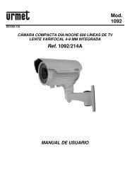
<strong>Mod</strong>.<br />
<strong>1092</strong><br />
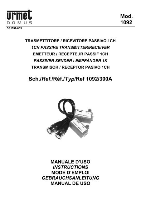
TRASMETTITORE / RICEVITORE PASSIVO 1CH<br />
1CH PASSIVE TRANSMITTER/RECEIVER<br />
EMETTEUR / RECEPTEUR PASSIF 1CH<br />
PASSIVER SENDER / EMPFÄNGER 1K<br />
TRANSMISOR / RECEPTOR PASIVO 1CH<br />
<strong>Sch</strong>./<strong>Ref</strong>./Réf./<strong>Typ</strong>/<strong>Ref</strong> <strong>1092</strong>/<strong>300A</strong><br />
MANUALE D’USO<br />
INSTRUCTIONS<br />
MODE D’EMPLOI<br />
GEBRAUCHSANLEITUNG<br />
MANUAL DE USO
ITALIANO<br />
INFORMAZIONI GENERALI<br />
Il presente documento descrive come installare ed utilizzare il modello di trasmettitore / ricevitore passivo a<br />
1 canale URMET Domus S.p.A. <strong>Sch</strong>.<strong>1092</strong>/<strong>300A</strong>.<br />
Prima di usare l’apparecchiatura, leggere il presente manuale che ne descrive l’uso corretto e sicuro.<br />
Conservare questo manuale con attenzione ed in un luogo facilmente reperibile per poterlo consultare<br />
prontamente quando necessario.<br />
DESCRIZIONE PRODOTTO<br />
Il prodotto URMET Domus S.p.A. <strong>Sch</strong>.<strong>1092</strong>/<strong>300A</strong> è costituito da una coppia di dispositivi passivi (senza<br />
amplificazione di segnale), che permettendo l’adattamento di impedenza tra cavo coassiale e cavo UTP,<br />
vengono utilizzati per la trasmissione / ricezione di un segnale video, bianco/nero o colori, su cavo UTP<br />
(Unshielded Twisted Pair). Tali dispositivi vengono comunemente detti VIDEO BALUN (balanced /<br />
unbalanced).<br />
Il segnale video trasmesso sul cavo UTP CAT5 da questo dispositivo viene bilanciato e ripartito equamente<br />
sulla coppia twistata, rendendo la ricetrasmissione molto più sicura contro le interferenze rispetto alla<br />
classica ricetrasmissione video su cavo coassiale.<br />
Il cavo UTP è un cavo formato da 4 coppie di conduttori di rame isolati ed intrecciati tra loro (twistati).<br />
Caratteristiche generali<br />
‣ Dimensioni compatte per una connessione semplice ad apparati di gestione video, monitor e<br />
telecamere.<br />
‣ Estrema facilità di impiego grazie alla presenza del BNC maschio e della morsettiera.<br />
‣ Nessuna alimentazione richiesta.<br />
‣ Doppia impedenza e filtro disturbi per garantire maggiore sicurezza contro le interferenze.<br />
APERTURA DELLA CONFEZIONE<br />
Verificare che l’imballo ed il contenuto non presentino danni visibili. Se alcune parti non sono presenti o<br />
risultano danneggiate, contattare immediatamente il rivenditore. In questi casi non tentare di utilizzare il<br />
dispositivo. Se il prodotto dovesse essere rimandato al fornitore, assicurarsi di spedirlo con il suo imballo<br />
originale.<br />
Contenuto della confezione<br />
‣ N°2 ricetrasmettitori con cavo intestato BNC.<br />
‣ Manuale d’uso.<br />
AVVERTENZE<br />
• Assicurarsi dell’integrità dell’apparecchio dopo averlo tolto dall’imballo.<br />
• Prima di effettuare qualsiasi operazione di pulizia o di manutenzione disinserire l’apparecchio dalla<br />
rete di alimentazione elettrica. Non usare prodotti spray per la pulizia dell’apparecchio.<br />
• Controllare che la temperatura d’esercizio sia nei limiti indicati e che l’ambiente non sia<br />
particolarmente umido.<br />
• In caso di guasto e/o cattivo funzionamento togliere l’alimentazione tramite l’interruttore generale.<br />
• Il dispositivo deve essere aperto soltanto da personale tecnico qualificato.<br />
• Per le riparazioni rivolgersi solo ad un centro di assistenza tecnica autorizzato.<br />
• Il collegamento dei balun non necessita di particolari componenti, ma occorre prestare attenzione agli<br />
ingombri qualora venisse utilizzato su dispositivi all’interno di custodie, con staffa a muro o armadi<br />
rack.<br />
2<br />
DS<strong>1092</strong>-035
INSTALLAZIONE<br />
1. Prima d’iniziare l’installazione, assicurarsi che tutte le unità da collegare non siano alimentate.<br />
2. Sguainare il cavo UTP CAT5 per circa 20 mm avendo cura di non tagliare i conduttori.<br />
3. Tagliare, scegliendo tra quelli liberi, i conduttori del colore relativo alla sorgente video da collegare.<br />
Nota Bene<br />
Per impianti a singolo segnale video, su un solo cavo UTP, si consiglia di utilizzare la coppia 4<br />
(bianco / marrone - marrone).<br />
4. Spellare i conduttori prescelti per circa 5 mm ed inserirli nel connettore prestando attenzione alla<br />
polarità in quanto il segnale video su cavo UTP è polarizzato (vedere tabella 1).<br />
COLORI / POLARITÀ CAVO UTP<br />
COPPIA COLORE POLARITÀ<br />
1<br />
Bianco-verde +<br />
Verde -<br />
2<br />
Bianco-arancio +<br />
Arancio -<br />
3<br />
Bianco-blu +<br />
Blu -<br />
4<br />
Bianco-marrone +<br />
Marrone -<br />
Tabella 1<br />
5. Serrare i morsetti con l’ausilio di un cacciavite.<br />
6. Collegare il BNC all’uscita video della sorgente video se impiegato come trasmettitore, oppure<br />
all’ingresso all’utilizzatore previsto (monitor o sistemi di gestione video) se impiegato come ricevitore.<br />
7. Alimentare la sorgente video e l’utilizzatore.<br />
Nota Bene<br />
Occorre, comunque, prestare molta attenzione al collegamento fisico che si intende realizzare.<br />
Nonostante il VIDEO BALUN consenta il trasporto del segnale video su un cavo UTP normalmente usato<br />
nelle reti informatiche, non vi è assolutamente alcuna compatibilità elettrica con i segnali presenti<br />
nella rete. Per questo motivo utilizzare dei VIDEO BALUN con dei cavi già usati in reti informatiche<br />
esistenti richiede estrema attenzione e cautela.<br />
IMPIEGO<br />
Il dispositivo <strong>Sch</strong>.<strong>1092</strong>/<strong>300A</strong> può essere impiegato sia come trasmettitore sia come ricevitore.<br />
Impiego come trasmettitore (TX)<br />
Impiegato come trasmettitore consente di poter connettere una sorgente video utilizzando una sola coppia<br />
twistata di un cavo UTP CAT5 dedicato. Può essere abbinato ai seguenti ricevitori:<br />
‣ <strong>Sch</strong>.<strong>1092</strong>/<strong>300A</strong> → “Trasmettitore / Ricevitore passivo 1ch”<br />
‣ <strong>Sch</strong>.<strong>1092</strong>/303 → “Ricevitore attivo 1ch”<br />
‣ <strong>Sch</strong>.<strong>1092</strong>/304 → “Ricevitore attivo 4ch”<br />
‣ <strong>Sch</strong>.<strong>1092</strong>/316 → “Ricevitore attivo 16ch”<br />
Impiego come ricevitore (RX)<br />
Impiegato come ricevitore viene collegato direttamente al BNC del lato utilizzatore: sistemi di gestione<br />
video (DVR, quad, ecc) o monitor.<br />
Tale impiego può essere abbinato solo con il trasmettitore passivo: <strong>Sch</strong>.<strong>1092</strong>/<strong>300A</strong>.<br />
DS<strong>1092</strong>-035 3
CARATTERISTICHE TECNICHE<br />
Ingresso / uscita video:.............................................................................................................. BNC maschio<br />
Ingresso / uscita cavo UTP:........................................................................................................... Morsettiera<br />
Tipo di cavo consigliato: ...............................................................................24 AWG UTP CAT5 o superiore<br />
........................................................................... Impedenza 100 Ω ± 20%, resistenza DC loop 18 Ω/100 m<br />
Impedenza BNC: .......................................................................................................................................75 Ω<br />
Impedenza UTP:......................................................................................................................................100 Ω<br />
Protezione sovratensioni: .............................................................................................................................. Si<br />
Temperatura di utilizzo: ......................................................................................................................-10÷45°c<br />
Temperatura d’immagazzinamento:................................................................................................... -30÷60°c<br />
Umidità: ................................................................................................................................................. 0÷95%<br />
Dimensioni (L x H x P):.......................................................................................................... 30 x 15 x 14 mm<br />
Peso (cad.): .............................................................................................................................................. 30 gr<br />
Nota Bene<br />
Le caratteristiche tecniche possono essere soggette a variazione senza alcun preavviso.<br />
APPLICAZIONI<br />
A seconda della distanza tra il lato sorgente e quello utilizzatore, far riferimento alla tabella 2 per la scelta<br />
dei VIDEO BALUN attivi / passivi e trasmettitori / ricevitori da impiegare per la realizzazione dell’impianto.<br />
Nota Bene<br />
Applicazione N° Telecamere<br />
Distanze per<br />
telecamere<br />
VIDEO BALUN<br />
b/n - colore (m)<br />
da a TX RX<br />
A 1 0 250<br />
<strong>Sch</strong>. <strong>Sch</strong>.<br />
<strong>1092</strong>/<strong>300A</strong> <strong>1092</strong>/<strong>300A</strong><br />
B 1 250 1200<br />
<strong>Sch</strong>. <strong>Sch</strong>.<br />
<strong>1092</strong>/<strong>300A</strong> <strong>1092</strong>/303<br />
C 4 250 1200<br />
<strong>Sch</strong>. <strong>Sch</strong>.<br />
<strong>1092</strong>/<strong>300A</strong> <strong>1092</strong>/304<br />
D 16 250 1200<br />
<strong>Sch</strong>.<br />
<strong>1092</strong>/<strong>300A</strong><br />
Tabella 2: distanze con cavo 24 AWG UTP CAT5<br />
<strong>Sch</strong>.<br />
<strong>1092</strong>/316<br />
• La tabella 2 fornisce una indicazione di massima delle distanze, con una tolleranza di circa ± 50m.<br />
• Le distanze possono variare in funzione della qualità del cavo, anche quando quest’ultimo risulta<br />
essere dello stesso tipo / costruttore.<br />
• Nel caso in cui tali dispositivi vengano impiegati con apparati DVR, occorre tenere in considerazione<br />
che le distanze indicate potrebbero subire un decremento.<br />
4<br />
DS<strong>1092</strong>-035
SCHEMI<br />
Qui di seguito si riportano alcuni schemi relativi ad applicazioni di base e di uso comune per il<br />
dispositivo <strong>Sch</strong>.<strong>1092</strong>/<strong>300A</strong>.<br />
Balun lato sorgente: <strong>Sch</strong>.<strong>1092</strong>/<strong>300A</strong><br />
A<br />
Balun lato utilizzatore: <strong>Sch</strong>.<strong>1092</strong>/<strong>300A</strong><br />
Applicazione con 1 telecamera<br />
Applicazione con 4 telecamere<br />
Balun lato sorgente: <strong>Sch</strong>.<strong>1092</strong>/<strong>300A</strong><br />
B<br />
Balun lato utilizzatore: <strong>Sch</strong>.<strong>1092</strong>/303<br />
DS<strong>1092</strong>-035 5
Balun lato sorgente: <strong>Sch</strong>.<strong>1092</strong>/<strong>300A</strong><br />
C<br />
Balun lato utilizzatore: <strong>Sch</strong>.<strong>1092</strong>/304<br />
OPPURE<br />
* Il dispositivo <strong>1092</strong>/304 dispone di due tipologie di ingressi per il segnale UTP: su morsettiera o su<br />
connettore RJ45. La scelta dell’ingresso da utilizzare è legata alla soluzione installativa che si<br />
intende realizzare.<br />
Balun lato sorgente: <strong>Sch</strong>.<strong>1092</strong>/<strong>300A</strong><br />
D<br />
Balun lato utilizzatore: <strong>Sch</strong>.<strong>1092</strong>/316<br />
1÷16<br />
Nota Bene<br />
Per informazioni più dettagliate e schemi relativi ad applicazioni più avanzate si consiglia di consultare il<br />
manuale tecnico sui sistemi di trasmissione video.<br />
6<br />
DS<strong>1092</strong>-035
ENGLISH<br />
GENERAL INFORMATION<br />
This document shows how to install and use the URMET Domus 1 channel passive transmitter/receiver<br />
<strong>Ref</strong>. <strong>1092</strong>/<strong>300A</strong>.<br />
Read this manual which contains information for correct, safe use carefully.<br />
Keep this manual at hand so that you can refer to it when needed.<br />
PRODUCT DESCRIPTION<br />
URMET Domus S.p.A. <strong>Ref</strong>.<strong>1092</strong>/<strong>300A</strong> consists of a pair of passive devices (without signal amplification)<br />
allowing for impedance adaptation between coaxial cable and UTP cable. The devices are used to transmit<br />
and receive a black and white or colour video signal on UTP (Unshielded Twisted Pair) cable. These<br />
devices are commonly known as VIDEO BALUN (balanced / unbalanced) devices.<br />
The video signal transmitted on the UTP CAT5 cable by this device is balanced and equally split on the<br />
twisted pair thus making transceiving more protected from interference with respect to traditional video<br />
transceiving on a coaxial cable.<br />
The UTP cable is formed by four pairs of insulated, twisted copper wires.<br />
General features<br />
‣ Compact dimensions for quick connection to video management apparatuses, monitors and<br />
cameras.<br />
‣ Very easy to use thanks to the presence of a male BNC and a terminal board.<br />
‣ No power needed.<br />
‣ Double impedance and interference filter for ensuring better protection from interference.<br />
OPENING THE BOX<br />
Check that the packing and the contents are not visibly damaged. Contact the retailer immediately if parts<br />
are either missing or damaged. Do not attempt to use the device in this case. Send the product back in its<br />
original packing if it is damaged.<br />
Contents of the box<br />
‣ N°2 transceivers with BNC plug cable.<br />
‣ Instruction manual.<br />
PRECAUTIONS<br />
• Make sure that the device is intact after removing it from the package.<br />
• Disconnect the device from the mains before cleaning or maintenance. Do not use spray products to<br />
clean the device.<br />
• Check that the working temperature is within the indicated range and that the environment is not<br />
particularly humid.<br />
• Disconnect power by means of the circuit breaker in the event of a failure and/or bad operation.<br />
• The device can only be opened by qualified technical personnel.<br />
• Exclusively contact an authorised service centre for repairs.<br />
• No special components are needed for connecting the balun devices but care must be devoted to<br />
dimensions if the devices are installed inside casings, on wall brackets or on racks.<br />
DS<strong>1092</strong>-035 7
INSTALLATION<br />
1. Make sure that no units are powered before starting the installation procedure.<br />
2. Strip the UTP CAT5 cable by approximately 20 mm making sure you do not cut the wires.<br />
3. Cut the wire whose colour corresponds to that of the video source to be connected. Choose one of<br />
the free wires.<br />
Important note:<br />
It is advisable to use the 4 wire pair (white/brown - brown) for single video signal systems on one only<br />
UTP.<br />
4. Strip the chosen wires by approximately 5 mm and insert them in the connector making sure that the<br />
polarity is correct because the UTP video signal is polarised (see table 1).<br />
UTP WIRE COLOURS/POLARITY<br />
PAIR COLOUR POLARITY<br />
1<br />
White-green +<br />
Green -<br />
2<br />
White-orange +<br />
Orange -<br />
3<br />
White-blue +<br />
Blue -<br />
4<br />
White-brown +<br />
Brown -<br />
Table 1<br />
Pair 1<br />
Pair 2<br />
Pair 3<br />
Pair 4<br />
5. Connect the terminals using a screwdriver.<br />
6. Connect the BVC to the video source output if it is used as a transmitter or to the required user input<br />
(monitor or video management system) if used as a receiver.<br />
7. Power the video source and user.<br />
Important note:<br />
Consider the physical connection to be made with the utmost attention.<br />
Although the video balun system allows to carry video signals on UTP cables generally used in IT systems,<br />
the balun system will not be electrically compatible with the signals present online in any way. For<br />
this reason, the utmost care is required when installing a video balun system using wires already installed<br />
in an IT network.<br />
USE<br />
The <strong>1092</strong>/<strong>300A</strong> device may be used either as a transmitter or as a receiver.<br />
Use as a transmitter (TX)<br />
Used as a transmitter, the device allows to connect a video source using one pair of twisted wires in a<br />
dedicated UTP CAT5 cable. It may be used in combination with the following receivers:<br />
‣ <strong>Ref</strong>.<strong>1092</strong>/<strong>300A</strong> → “1ch passive transmitter/receiver”<br />
‣ <strong>Ref</strong>.<strong>1092</strong>/303 → “1ch active receiver”<br />
‣ <strong>Ref</strong>.<strong>1092</strong>/304 → “4ch active receiver”<br />
‣ <strong>Ref</strong>.<strong>1092</strong>/316 → “16ch active receiver”<br />
Use as receiver (RX)<br />
When used as a receiver, the device is directly plugged into the BNC on video management system user<br />
(DVR, quad, etc.) or monitor side.<br />
This use is only possible in combination with passive transmitter <strong>Ref</strong>. <strong>1092</strong>/<strong>300A</strong>.<br />
8<br />
DS<strong>1092</strong>-035
TECHNICAL SPECIFICATIONS<br />
Video input/output:............................................................................................................................Male BNC<br />
UTP cable input/output:...........................................................................................................Terminal board<br />
Recommended wire type:.................................................................................24 AWG UTP CAT5 or higher<br />
...........................................................................Impedance 100 Ω ± 20%, resistance DC loop 18 Ω/100 m<br />
BNC impedance: .......................................................................................................................................75 Ω<br />
UTP impedance:......................................................................................................................................100 Ω<br />
Voltage surge protection:............................................................................................................................ Yes<br />
Working temperature range:............................................................................................................... -10-45°C<br />
Storage temperature range: ............................................................................................................... -30-60°C<br />
Humidity:................................................................................................................................................. 0-95%<br />
Dimensions (W x H x D): ....................................................................................................... 30 x 15 x 14 mm<br />
Weight (each): ........................................................................................................................................... 30 g<br />
Important note:<br />
Technical features may be subject to change without prior notice.<br />
APPLICATIONS<br />
<strong>Ref</strong>er to table 2 to select the active/passive transmitters and receivers to be used for system installation<br />
according to the distance between source and user.<br />
Important note:<br />
Application N. of cameras<br />
Camera distance<br />
b/w - colour (m)<br />
VIDEO BALUN<br />
from to TX RX<br />
A 1 0 250<br />
<strong>Ref</strong>.<br />
<strong>Ref</strong>.<br />
<strong>1092</strong>/<strong>300A</strong> <strong>1092</strong>/<strong>300A</strong><br />
B 1 250 1200<br />
<strong>Ref</strong>.<br />
<strong>Ref</strong>.<br />
<strong>1092</strong>/<strong>300A</strong> <strong>1092</strong>/303<br />
C 4 250 1200<br />
<strong>Ref</strong>.<br />
<strong>Ref</strong>.<br />
<strong>1092</strong>/<strong>300A</strong> <strong>1092</strong>/304<br />
D 16 250 1200<br />
<strong>Ref</strong>.<br />
<strong>Ref</strong>.<br />
<strong>1092</strong>/<strong>300A</strong> <strong>1092</strong>/316<br />
Table 2: distances with 24 AWG UTP CAT5 cable<br />
• Table 2 shows the approximate maximum distances with a tolerance of approximately ± 50m.<br />
• The distances may vary according to the wire quality also when the latter is made by the same<br />
manufacturer as the devices.<br />
• Consider that the distances may decrease if the devices are used with DVR apparatuses.<br />
DS<strong>1092</strong>-035 9
DIAGRAMS<br />
Some diagrams related to basic applications and common use of the <strong>Ref</strong>. <strong>1092</strong>/<strong>300A</strong> device are shown<br />
below.<br />
Balun source side: <strong>Ref</strong>.<strong>1092</strong>/<strong>300A</strong><br />
A<br />
Balun user side: <strong>Ref</strong>.<strong>1092</strong>/<strong>300A</strong><br />
Application with 1 camera<br />
Application with 4 cameras<br />
Balun source side: <strong>Ref</strong>.<strong>1092</strong>/<strong>300A</strong><br />
B<br />
Balun user side: <strong>Ref</strong>.<strong>1092</strong>/303<br />
10<br />
DS<strong>1092</strong>-035
Balun source side: <strong>Ref</strong>.<strong>1092</strong>/<strong>300A</strong><br />
C<br />
Balun user side: <strong>Ref</strong>.<strong>1092</strong>/304<br />
OR<br />
* The <strong>1092</strong>/304 device has two UTP signal input types (terminal board or RJ45 connector). Choose<br />
either one or the other according to the installation solution you want.<br />
Balun source side: <strong>Ref</strong>.<strong>1092</strong>/<strong>300A</strong><br />
D<br />
Balun user side: <strong>Ref</strong>.<strong>1092</strong>/316<br />
1÷16<br />
Important note:<br />
<strong>Ref</strong>er to the video transmission system technical manual for more detailed information and most complex<br />
application diagrams.<br />
DS<strong>1092</strong>-035 11
FRANÇAIS<br />
GENERALITES<br />
Le présent document décrit l’installation et le mode d’utilisation du modèle d'émetteur/récepteur passif à<br />
une voie URMET Domus S.p.A., Réf.<strong>1092</strong>/<strong>300A</strong>.<br />
Avant d'utiliser l'équipement, lire le présent manuel, qui en décrit le fonctionnement correct et sûr.<br />
Conserver le présent manuel avec soin et dans un lieu facilement identifiables pour pouvoir le consulter<br />
aisément en cas de besoin.<br />
DESCRIPTION DU PRODUIT<br />
Le produit URMET Domus S.p.A. Réf.<strong>1092</strong>/<strong>300A</strong> se compose d'une paire de dispositifs passifs (sans<br />
amplification de signal) qui, en permettant l'adaptation d'impédance entre le câble coaxial et le câble UTP,<br />
sont utilisés pour l'émission/réception d'un signal vidéo, en noir/blanc ou couleurs, sur un câble UTP<br />
(Unshielded Twisted Pair). Ces dispositifs sont généralement appelés VIDEO BALUN (balanced /<br />
unbalanced).<br />
Le signal vidéo transmis sur le câble UTP CAT5 par ce dispositif est équilibré et également réparti sur la<br />
paire torsadée, en rendant l'émission/réception mieux protégée contre les interférences par rapport à<br />
l'émission/réception vidéo sur câble axiale.<br />
Le câble UTP est constitué de quatre paires de conducteurs en cuivre isolés et torsadés (twistés).<br />
Caractéristiques générales<br />
‣ Dimensions compactes pour une connexion aisée à des appareils de gestion vidéo, des écrans<br />
ou des caméras.<br />
‣ Grande facilité d'utilisation, grâce à la présence du BNC mâle et du bornier.<br />
‣ Aucune alimentation n'est requise.<br />
‣ Double impédance et filtre à perturbations pour assurer une meilleure protection contre les<br />
interférences.<br />
OUVERTURE DE L'EMBALLAGE<br />
Vérifier que l’emballage et son contenu ne présentent aucun dommage visible. S’il manque une pièce ou si<br />
des pièces sont endommagées, contacter immédiatement le revendeur. Ne tenter d’utiliser le dispositif, en<br />
aucun cas. Si nécessaire, le produit doit impérativement être retourné au fournisseur dans son emballage<br />
d’origine.<br />
Contenu de l’emballage<br />
‣ N°2 émetteurs/rècepteurs avec câble abouté BNC.<br />
‣ Manuel utilisateur.<br />
AVERTISSEMENTS<br />
• Après avoir retiré l’emballage, s’assurer de l’état intact de l’appareil.<br />
• Avant de procéder à toute opération de nettoyage ou de maintenance, débrancher l’appareil du<br />
secteur. Ne pas utiliser de produits en spray pour le nettoyage de l’appareil.<br />
• Vérifier que la température de fonctionnement est conforme aux limites indiquées et que<br />
l'environnement ne présente pas une humidité excessive.<br />
• En cas de panne et/ou de fonctionnement irrégulier, couper l’alimentation à l’aide de l’interrupteur<br />
général.<br />
• Seul un personnel technique qualifié peut ouvrir le dispositif.<br />
• Pour les réparations, s’adresser uniquement à un centre après-vente agréé par le constructeur.<br />
• Le raccordement des baluns ne requiert pas de composants particuliers; il est quand même<br />
nécessaire de veiller aux encombrements, en cas d'utilisation sur des dispositifs renfermés dans des<br />
boîtiers, avec un étrier mural ou dans des baies.<br />
12<br />
DS<strong>1092</strong>-035
INSTALLATION<br />
1. Avant de procéder à l'installation, s'assurer que toutes les unités à brancher sont hors tension.<br />
2. Dégainer le câble UTP CAT5 sur environ 20 mm, en veillant à ne pas couper les conducteurs.<br />
3. Parmi les conducteurs libres, couper ceux dont la couleur correspond à la source vidéo à brancher.<br />
N.B. :<br />
Pour les installations à simple signal vidéo, sur un seul câble UTP, il est conseillé d'utiliser la paire de<br />
câbles 4 (blanc / marron - marron).<br />
4. Dégainer les conducteurs choisis sur environ 5 mm et les introduire dans le connecteur, en veillant à<br />
leur polarité, car le signal vidéo sur câble UTP est polarisé (voir tableau 1).<br />
COULEURS / POLARITE CABLE UTP<br />
PAIRE COULEUR POLARITE<br />
1<br />
Blanc-vert +<br />
Vert -<br />
2<br />
Blanc-orange +<br />
Orange -<br />
3<br />
Blanc-bleu +<br />
Bleu -<br />
4<br />
Blanc-marron +<br />
Marron -<br />
Paire 1<br />
Paire 2<br />
Paire 3<br />
Paire 4<br />
Tableau 1<br />
5. Serrer les bornes à l'aide d'un tournevis.<br />
6. Raccorder le BNC à la sortie vidéo de la source vidéo, si utilisé en guise d'émetteur, ou à la sortie de<br />
l'utilisateur prévu (écran ou systèmes de gestion vidéo), si utilisé en guise de récepteur.<br />
7. Alimenter la source vidéo et l’utilisateur.<br />
N.B. :<br />
Il est néanmoins nécessaire de porter une extrême attention au raccordement physique à réaliser.<br />
Bien que le VIDEO BALUN permette le transfert du signal vidéo sur un câble UTP normalement utilisé sur<br />
les réseaux informatiques, il n'y a absolument aucune compatibilité électrique avec les signaux<br />
présents sur le réseau. C'est pourquoi l'utilisation des VIDEO BALUNS avec des câbles déjà employés<br />
sur les réseaux informatiques existants, exige beaucoup d'attention et de prudence.<br />
UTILISATION<br />
Le dispositif Réf.<strong>1092</strong>/<strong>300A</strong> peut être utilisé en guise aussi bien d'émetteur que de récepteur.<br />
Utilisation en guise d'émetteur (TX)<br />
Si utilisé en guise d'émetteur, il permet de connecter une source vidéo en utilisant une seule paire torsadée<br />
d'un câble UTP CAT5 dédié. Il peut être associé aux récepteurs suivants :<br />
‣ Réf.<strong>1092</strong>/<strong>300A</strong> → “Emetteur / Récepteur passif 1ch”<br />
‣ Réf.<strong>1092</strong>/303 → “Récepteur actif 1ch”<br />
‣ Réf.<strong>1092</strong>/304 → “Récepteur actif 4ch”<br />
‣ Réf.<strong>1092</strong>/316 → “Récepteur actif 16ch”<br />
Utilisation en guise de récepteur (RX)<br />
Si utilisé en guise de récepteur, il est directement raccordé au BNC, côté utilisateur : systèmes de gestion<br />
vidéo (DVR, quad, etc.) ou écrans.<br />
Dan ce cas, il ne peut être associé qu'à un émetteur passif : Réf.<strong>1092</strong>/<strong>300A</strong>.<br />
DS<strong>1092</strong>-035 13
CARACTERISTIQUES TECHNIQUES<br />
Entrée / sortie vidéo :........................................................................................................................BNC mâle<br />
Entrée / sortie câble UTP : ...................................................................................................................Bornier<br />
<strong>Typ</strong>e de câble conseillé :........................................................................... 24 AWG UTP CAT5 ou supérieur<br />
...........................................................................Impédance 100 Ω ± 20%, résistance DC loop 18 Ω/100 m<br />
Impédance BNC : ......................................................................................................................................75 Ω<br />
Impédance UTP :.....................................................................................................................................100 Ω<br />
Protection contre les surtensions : ..............................................................................................................Oui<br />
Température de fonctionnement :...................................................................................................... -10÷45°C<br />
Température de stockage : ............................................................................................................... -30÷60°C<br />
Humidité : .............................................................................................................................................. 0÷95%<br />
Dimensions (L x H x P): ......................................................................................................... 30x 15 x 14 mm<br />
Poids (chaque) : ....................................................................................................................................... 30 gr<br />
N.B. :<br />
Les caractéristiques techniques peuvent varier sans préavis.<br />
APPLICATIONS<br />
En fonction de la distance entre les côtés source et utilisateur, se reporter au tableau 2 pour choisir les<br />
VIDEO BALUNS actifs / passifs et les émetteurs / récepteurs à utiliser pour réaliser l'installation.<br />
N.B. :<br />
Application<br />
N.bre de<br />
caméras<br />
A 1 0 250<br />
B 1 250 1200<br />
C 4 250 1200<br />
D 16 250 1200<br />
Distances pour<br />
caméras<br />
VIDEO BALUN<br />
n/b - couleurs (m)<br />
de à TX RX<br />
Réf.<br />
Réf.<br />
<strong>1092</strong>/<strong>300A</strong> <strong>1092</strong>/<strong>300A</strong><br />
Réf.<br />
Réf.<br />
<strong>1092</strong>/<strong>300A</strong> <strong>1092</strong>/303<br />
Réf.<br />
Réf.<br />
<strong>1092</strong>/<strong>300A</strong> <strong>1092</strong>/304<br />
Réf.<br />
<strong>1092</strong>/<strong>300A</strong><br />
Tableau 2: distances avec câble 24 AWG UTP CAT5<br />
Réf.<br />
<strong>1092</strong>/316<br />
• Le tableau 2 donne une indication de principe des distances, avec une tolérance d'environ ± 50m.<br />
• Les distances peuvent varier en fonction de la qualité du câble, et ce même lorsque celui-ci est du<br />
même type/fabricant que celui prescrit.<br />
• Lorsque ces dispositifs sont utilisés avec des appareils DVR, il faut rappeler que les distances<br />
indiquées pourraient subir une réduction.<br />
14<br />
DS<strong>1092</strong>-035
SCHEMAS<br />
Voici quelques schémas relatifs à des applications de base et d'usage courant du dispositif Réf.<br />
<strong>1092</strong>/<strong>300A</strong>.<br />
Balun côté source : Réf.<strong>1092</strong>/<strong>300A</strong><br />
A<br />
Balun côté utilisateur : Réf.<strong>1092</strong>/<strong>300A</strong><br />
Application avec une caméra<br />
Application avec quatre caméras<br />
Balun côté source : Réf.<strong>1092</strong>/<strong>300A</strong><br />
B<br />
Balun côté utilisateur : Réf.<strong>1092</strong>/303<br />
DS<strong>1092</strong>-035 15
Balun côté source : Réf.<strong>1092</strong>/<strong>300A</strong><br />
C<br />
Balun côté utilisateur : Réf.<strong>1092</strong>/304<br />
OU BIEN<br />
* Le dispositif <strong>1092</strong>/304 comporte deux typologies d'entrées pour le signal UTP : sur bornier ou sur<br />
connecteur RJ45. Le choix de l'entrée dépend de la solution d'installation à réaliser.<br />
Balun côté source : Réf.<strong>1092</strong>/<strong>300A</strong><br />
D<br />
Balun côté utilisateur : Réf.<strong>1092</strong>/316<br />
1÷16<br />
N.B. :<br />
Pour plus d'informations et pour les schémas relatifs à des applications plus avancées, se reporter au<br />
manuel technique des systèmes de transmission vidéo.<br />
16<br />
DS<strong>1092</strong>-035
DEUTSCH<br />
ALLGEMEINE INFORMATIONEN<br />
Dieses Dokument beschreibt die Installation und den Einsatz des <strong>Mod</strong>ells des passiven Senders /<br />
Empfängers mit 1 Kanal von URMET Domus S.p.A. <strong>Typ</strong> <strong>1092</strong>/<strong>300A</strong>.<br />
Vor dem Gebrauch des Geräts diese Gebrauchsanleitung lesen, die dessen korrekten und sicheren<br />
Gebrauch beschreibt.<br />
Diese Gebrauchsanleitung sorgsam und an einem leicht zugänglichen Ort aufbewahren, um sie bei Bedarf<br />
umgehend konsultieren zu können.<br />
PRODUKTBESCHREIBUNG<br />
Das Produkt von URMET Domus S.p.A. <strong>1092</strong>/<strong>300A</strong> besteht aus einem Paar passiver Bauteile (ohne<br />
Signalverstärkung), die, da sie die Impedanzanpassung zwischen Koaxialkabel und UTP-Kabel gestatten,<br />
für die Übertragung / den Empfang eines Videosignals in schwarz-weiß oder in Farbe auf dem UTP-Kabel<br />
(Unshielded Twisted Pair) eingesetzt werden. Diese Bauteile werden im allgemeinen VIDEO BALUN<br />
(ausgeglichen / nicht ausgeglichen) genannt.<br />
Das auf dem UTP-Kabel CAT5 von diesem Bauteil übertragene Signal wird ausgeglichen und gleichmäßig<br />
auf dem verdrillten Paar verteilt und bietet so einen besseren <strong>Sch</strong>utz der Übertragung und des Empfangs<br />
gegen Interferenzen im Vergleich zur herkömmlichen Art der Übertragung und des Empfangs auf<br />
Koaxialkabel.<br />
Das UTP-Kabel ist ein aus vier isolierten und untereinander verflochtenen (verdrillten) Kupferleiterpaaren<br />
bestehendes Kabel.<br />
Allgemeine Merkmale<br />
‣ Kompakte Abmessungen für einen einfachen Anschluss an Videosysteme, Monitore und<br />
Kameras.<br />
‣ Extrem einfache Verwendung dank des BNC-Steckers und der Klemmenleiste.<br />
‣ Keinerlei Versorgung erforderlich.<br />
‣ Doppelte Impedanz und Störfilter, um größeren <strong>Sch</strong>utz gegen Interferenzen zu garantieren.<br />
ÖFFNEN DER VERPACKUNG<br />
Überprüfen, ob die Verpackung und der Inhalt keine erkennbaren <strong>Sch</strong>äden aufweisen. Fehlen Teile oder<br />
erweisen diese sich als beschädigt, unmittelbar den Händler kontaktieren. In diesen Fällen nicht<br />
versuchen, das Gerät zu verwenden. Muss das Produkt an den Lieferanten zurückgeschickt werden,<br />
vergewissern Sie sich, dass dies in der Originalverpackung erfolgt.<br />
Inhalt der Verpackung<br />
‣ N°2 Stück Sender-Empfänger mit BNC-Steckerleitung.<br />
‣ Gebrauchsanleitung.<br />
DS<strong>1092</strong>-035 17
HINWEISE<br />
• Nach dem Auspacken des Geräts muss sichergestellt werden, dass es sich in einwandfreiem<br />
Zustand befindet.<br />
• Vor dem Ausführen jeglicher Reinigungs- oder Wartungsarbeiten, das Gerät vom<br />
Stromversorgungsnetz trennen. Für die Reinigung des Geräts keine Sprays verwenden.<br />
• Überprüfen, ob die Betriebstemperatur sich innerhalb der angezeigten Grenzwerte befindet und die<br />
Umgebung nicht besonders feucht ist.<br />
• Bei Defekten und/oder mangelnder Funktionstüchtigkeit, die Versorgung über den Hauptschalter<br />
abschalten.<br />
• Das Gerät darf nur von qualifiziertem technischen Personal geöffnet werden.<br />
• Für Reparaturen wenden Sie sich bitte nur an ein autorisiertes Zentrum des technischen<br />
Kundendiensts.<br />
• Der Anschluss der Balun erfordert keine besonderen Komponenten, es muss jedoch auf die<br />
Abmessungen geachtet werden, sollte der Einsatz auf Bauelementen im Inneren von Gehäusen, mit<br />
Wandhalterung oder Rackschränken erfolgen.<br />
INSTALLATION<br />
1. Vor der Installation sicherstellen, dass alle anzuschließenden Einheiten von der Versorgung getrennt<br />
sind.<br />
2. Die Ummantelung des UTP-Kabels CAT5 ca. 20 mm entfernen und dabei darauf achten, die Leiter<br />
nicht zu durchschneiden.<br />
3. Durch Auswahl unter den freien Leitern die Leiter mit der jeweiligen Farbe der anzuschließenden<br />
Videoquelle zuschneiden.<br />
Beachten<br />
Für Anlagen mit einfachem Videosignal auf einem einzigen UTP-Kabel wird empfohlen, das<br />
Kabelpaar 4 (weiß/ braun - braun) zu verwenden.<br />
4. Von den ausgewählten Leitern die Ummantelung ca. 5 mm weit entfernen und diese in den Verbinder<br />
einführen. Dabei auf die Polarität achten, das das Videosignal auf UTP-Kabel polarisiert ist (siehe<br />
Tabelle 1).<br />
FARBEN / POLARITÄT UTP-KABEL<br />
PAAR FARBE POLARITÄT<br />
Weiß-grün +<br />
1<br />
Grün -<br />
Weiß-orange +<br />
2<br />
Orange -<br />
Weiß-Blau +<br />
3<br />
Blau -<br />
Weiß-braun +<br />
4<br />
Braun -<br />
Paar 1<br />
Paar 2<br />
Paar 3<br />
Paar 4<br />
Tabelle 1<br />
5. Die Klemmen mit Hilfe eines <strong>Sch</strong>raubenziehers anziehen.<br />
6. Den BNC an den Videoausgang der Videoquelle anschließen, wenn dieser als Sender verwendet<br />
wird oder an den Eingang des vorgesehenen Verbrauchers (Monitor oder Videosystem) beim Einsatz<br />
als Empfänger.<br />
7. Die Videoquelle und den Verbraucher mit Strom versorgen.<br />
18<br />
DS<strong>1092</strong>-035
Beachten<br />
Es muss auf jeden Fall bei der herzustellenden physischen Verbindung sehr vorsichtig vorgegangen<br />
werden.<br />
Obwohl der VIDEO BALUN den Transport des Videosignals auf ein normalerweise in den Computernetzen<br />
verwendetes UTP-Kabel gestattet, gibt es absolut keine elektrische Kompatibilität mit den im Netz<br />
vorhandenen Signalen. Aus diesem Grund den VIDEO BALUN mit bereits in bestehenden<br />
Computernetzen verwendeten Kabeln verwenden und sehr aufmerksam und vorsichtig vorgehen.<br />
EINSATZ<br />
Das Bauteil <strong>Typ</strong> <strong>1092</strong>/<strong>300A</strong> kann sowohl als Sender als auch als Empfänger eingesetzt werden.<br />
Einsatz als Sender (TX)<br />
Beim Einsatz als Sender gestattet es den Anschluss einer Videoquelle unter Verwendung eines einzigen<br />
verdrillten Paars eines speziellen UTP-Kabels CAT5. Es kann mit den folgenden Empfängern kombiniert<br />
werden:<br />
‣ <strong>Typ</strong> <strong>1092</strong>/<strong>300A</strong> → “Passiver Sender / Empfänger 1K”<br />
‣ <strong>Typ</strong> <strong>1092</strong>/303 → “Aktiver Empfänger 1K”<br />
‣ <strong>Typ</strong> <strong>1092</strong>/304 → “Aktiver Empfänger 4K”<br />
‣ <strong>Typ</strong> <strong>1092</strong>/316 → “Aktiver Empfänger 16K”<br />
Einsatz als Empfänger (RX)<br />
Beim Einsatz als Empfänger wird es direkt an den BNC der Verbraucherseite angeschlossen:<br />
Videosysteme (DVR, Quad, etc) oder Monitor.<br />
Dieser Einsatz kann nur mit dem passiven Sender kombiniert werden: <strong>Typ</strong> <strong>1092</strong>/<strong>300A</strong>.<br />
TECHNISCHE EIGENSCHAFTEN<br />
Videoeingang/-ausgang:..............................................................................................................BNC-Stecker<br />
Eingang / Ausgang UTP-Kabel:............................................................................................... Klemmenleiste<br />
Empfohlener Kabeltyp: ................................................................................. 24 AWG UTP CAT5 oder höher<br />
......................................................................... Impedanz 100 Ω ± 20 %, Widerstand DC Loop 18 Ω/100 m<br />
Impedanz BNC: .........................................................................................................................................75 Ω<br />
Impedanz UTP:........................................................................................................................................100 Ω<br />
Überspannungsschutz:..................................................................................................................................Ja<br />
Betriebstemperatur:........................................................................................................................... -10÷45°C<br />
Lagertemperatur:............................................................................................................................... -30÷60°C<br />
Luftfeuchtigkeit: ..................................................................................................................................... 0÷95%<br />
Abmessungen (B x H x T): .................................................................................................... 30 x 15 x 14 mm<br />
Gewicht (jeweils): ...................................................................................................................................... 30 g<br />
Beachten<br />
Die technischen Charakteristiken können Änderungen ohne Vorankündigung unterliegen.<br />
DS<strong>1092</strong>-035 19
ANWENDUNGEN<br />
Beziehen Sie sich abhängig von dem Abstand zwischen der Seite der Quelle und der des Verbrauchers<br />
hinsichtlich der Auswahl der in der Anlage zu verwendenden aktiven / passiven VIDEO BALUN und Sender<br />
/ Empfänger auf die Tabelle 2.<br />
Abstände für<br />
Kameras<br />
VIDEO BALUN<br />
Anwendung Anz. Kameras<br />
s/w – Farbe (m)<br />
von an TX RX<br />
A 1 0 250<br />
<strong>Typ</strong><br />
<strong>Typ</strong><br />
<strong>1092</strong>/<strong>300A</strong> <strong>1092</strong>/<strong>300A</strong><br />
B 1 250 1200<br />
<strong>Typ</strong><br />
<strong>Typ</strong><br />
<strong>1092</strong>/<strong>300A</strong> <strong>1092</strong>/303<br />
C 4 250 1200<br />
<strong>Typ</strong><br />
<strong>Typ</strong><br />
<strong>1092</strong>/<strong>300A</strong> <strong>1092</strong>/304<br />
D 16 250 1200<br />
<strong>Typ</strong><br />
<strong>1092</strong>/<strong>300A</strong><br />
<strong>Typ</strong><br />
<strong>1092</strong>/316<br />
Beachten<br />
Tabelle 2: Abstände mit Kabel 24 AWG UTP CAT5<br />
• Die Tabelle erteilt eine ungefähre Angabe der Abstände bei einer Toleranz von ca. ± 50 m.<br />
• Die Abstände können abhängig von der Qualität des Kabels variieren, auch wenn Letzteres<br />
desselben <strong>Typ</strong>s ist oder von demselben Hersteller stammt.<br />
• Sollten diese Bauteile mit DVR-Geräten verwendet werden, ist zu berücksichtigen, dass die<br />
angegebenen Abstände geringer sein könnten.<br />
20<br />
DS<strong>1092</strong>-035
PLÄNE<br />
Im Anschluss werden einige Pläne in Hinblick auf die Basisanwendungen und bezüglich des allgemeinen<br />
Einsatzes für das Bauteil <strong>Typ</strong> <strong>1092</strong>/<strong>300A</strong> aufgeführt.<br />
A<br />
Balun Quellenseite: <strong>Typ</strong> <strong>1092</strong>/<strong>300A</strong> Balun Verbraucherseite: <strong>Typ</strong> <strong>1092</strong>/<strong>300A</strong><br />
Verwendung mit 1 Kamera<br />
Verwendung mit 4 Kameras<br />
B<br />
Balun Quellenseite: <strong>Typ</strong> <strong>1092</strong>/<strong>300A</strong> Balun Verbraucherseite: <strong>Typ</strong> <strong>1092</strong>/303<br />
DS<strong>1092</strong>-035 21
C<br />
Balun Quellenseite: Karte <strong>1092</strong>/<strong>300A</strong> Balun Verbraucherseite: Karte <strong>1092</strong>/304<br />
ODER<br />
• Das Bauteil <strong>1092</strong>/304 verfügt über zwei Eingangsarten für das UTP-Signal: auf der<br />
Klemmenleiste oder auf RJ45-Verbinder. Die Auswahl des zu verwendenden Eingangs hängt<br />
mit der Installationslösung zusammen, die realisiert werden soll.<br />
D<br />
Balun Quellenseite: Karte <strong>1092</strong>/<strong>300A</strong> Balun Verbraucherseite: Karte <strong>1092</strong>/316<br />
1÷16<br />
Beachten<br />
Für weitere Informationen und Pläne hinsichtlich erweiterter Anwendungen wird empfohlen, sich auf das<br />
technische Handbuch der Videoübertragungssysteme zu beziehen.<br />
22<br />
DS<strong>1092</strong>-035
ESPAÑOL<br />
INFORMACIÓN GENERAL<br />
Este documento contiene la descripción de la instalación y el uso del modelo de transmisor / receptor<br />
pasivo de 1 canal URMET Domus S.p.A. <strong>Ref</strong>. <strong>1092</strong>/<strong>300A</strong>.<br />
Antes de utilizar el equipo, leer este manual que explica cómo usar el producto de manera correcta y<br />
segura.<br />
Conservar este manual en buenas condiciones y en un lugar de fácil acceso para poder consultarlo<br />
rápidamente en caso de necesidad.<br />
DESCRIPCIÓN DEL PRODUCTO<br />
El producto URMET Domus S.p.A. <strong>Ref</strong>. <strong>1092</strong>/<strong>300A</strong> está formado por una pareja de dispositivos pasivos<br />
(sin amplificación de señal), que permiten la adaptación de impedancia entre el cable coaxial y el cable<br />
UTP; se utilizan para la transmisión / recepción de una señal vídeo, en blanco/negro o de colores, por<br />
cable UTP (Unshielded Twisted Pair o par trenzado sin blindaje). Estos dispositivos se conocen como<br />
VIDEO BALUN (balanceado / no balanceado).<br />
La señal vídeo transmitida por cable UTP CAT5 desde este dispositivo se balancea y se reparte<br />
equitativamente en el par trenzado, haciendo que la recepción y la transmisión sean mucho más seguras<br />
contra las interferencias respecto de las tradicionales por cable coaxial.<br />
El cable UTP está formado por 4 pares de conductores de cobre aislados y trenzados.<br />
Características generales<br />
‣ Dimensiones compactas para una conexión sencilla con aparatos de control vídeo, monitores y<br />
cámaras TV.<br />
‣ Gran facilidad de uso gracias a la presencia del BNC macho y del tablero de bornes.<br />
‣ Ninguna alimentación necesaria.<br />
‣ Doble impedancia y filtro antiparásito para garantizar mayor seguridad contra las interferencias.<br />
APERTURA DEL EMBALAJE<br />
Comprobar que el embalaje y el contenido no presenten daños visibles. Si falta alguna pieza o si está<br />
dañada, ponerse inmediatamente en contacto con el revendedor. En dichos casos no se debe intentar<br />
utilizar el dispositivo. Si se debe devolver el producto al proveedor, asegurarse de enviarlo en su embalaje<br />
original.<br />
Contenido del embalaje<br />
‣ Dos trasmisores/receptores con latiguillo BNC.<br />
‣ Manual de uso.<br />
ADVERTENCIAS<br />
• Asegurarse de la integridad del dispositivo una vez abierto el embalaje.<br />
• Antes de realizar cualquier operación de limpieza o de mantenimiento, desconectar el aparato de la<br />
red de alimentación eléctrica. No usar productos en aerosol para la limpieza del aparato.<br />
• Controlar que la temperatura de funcionamiento se encuentre dentro de los límites indicados y que el<br />
medio ambiente no sea muy húmedo.<br />
• En caso de avería y/o defectos de funcionamiento, cortar la alimentación mediante el interruptor<br />
general.<br />
• El dispositivo sòlo puede ser manipulado internamente por personal tècnicamente cualificado.<br />
• Para las reparaciones dirigirse sólo a un centro de asistencia técnica autorizado.<br />
• La conexión de los balun no necesita componentes especiales, pero hay que prestar atención a las<br />
dimensiones ocupadas cuando se utiliza en dispositivos contenidos en cubiertas, con soporte de<br />
pared o armarios rack.<br />
DS<strong>1092</strong>-035 23
INSTALACIÓN<br />
1. Antes de empezar la instalación, asegurarse de que todas las unidades que se deben conectar estén<br />
sin alimentación.<br />
2. Cortar unos 20 mm de la vaina del cable UTP CAT5 con la precaución de no cortar los conductores.<br />
3. Cortar, escogiendo entre los libres, los conductores del color correspondiente a la fuente vídeo a<br />
conectar.<br />
Nota:<br />
Para los sistemas de una sola señal vídeo, en un solo cable UTP, se recomienda el uso del par de<br />
cables 4 (blanco / marrón – marrón).<br />
4. Pelar unos 5 mm los conductores escogidos e introducirlos en el conector, prestando atención a la<br />
polaridad, ya que la señal vídeo por cable UTP está polarizada (consultar la tabla 1).<br />
COLORES / POLARIDAD CABLE UTP<br />
PAR COLOR POLARIDAD<br />
1<br />
Blanco-verde +<br />
Verde -<br />
2<br />
Blanco-naranja +<br />
Naranja -<br />
3<br />
Blanco-azul +<br />
Azul -<br />
4<br />
Blanco-marrón +<br />
Marrón -<br />
Par 1<br />
Par 2<br />
Par 3<br />
Par 4<br />
Tabla 1<br />
5. Apretar los bornes con la ayuda de un destornillador.<br />
6. Conectar el BNC en la salida vídeo de la fuente vídeo, si se utiliza como transmisor, o en la entrada<br />
del equipo previsto (monitor o sistemas de control vídeo), si se utiliza como receptor.<br />
7. Dar alimentación a la fuente vídeo y al equipo conectado.<br />
Nota:<br />
Hay que prestar siempre mucha atención a la conexión física que se quiere realizar.<br />
Aunque el VIDEO BALUN permite el transporte de la señal vídeo por un cable UTP normalmente usado en<br />
las redes informáticas, no existe ninguna compatibilidad eléctrica con las señales presentes en la<br />
red. Por este motivo, utilizar los VIDEO BALUN con cables ya utilizados en redes informáticas existentes<br />
exige una gran atención y mucha precaución.<br />
USO<br />
El dispositivo <strong>Ref</strong>. <strong>1092</strong>/<strong>300A</strong> se puede utilizar como transmisor y como receptor.<br />
Uso como transmisor (TX)<br />
Utilizado como transmisor permite conectar una fuente vídeo usando un solo par trenzado de un cable<br />
UTP CAT5 dedicado. Se puede combinar con los siguientes receptores:<br />
‣ <strong>Ref</strong>. <strong>1092</strong>/<strong>300A</strong> → “Transmisor / Receptor pasivo 1ch”<br />
‣ <strong>Ref</strong>. <strong>1092</strong>/303 → “Receptor activo 1ch”<br />
‣ <strong>Ref</strong>. <strong>1092</strong>/304 → “Receptor activo 4ch”<br />
‣ <strong>Ref</strong>. <strong>1092</strong>/316 → “Receptor activo 16ch”<br />
Uso como receptor (RX)<br />
Utilizado como receptor se conecta directamente en el BNC del lado del equipo conectado: sistemas de<br />
control vídeo (DVR, quad, etc.) o monitor.<br />
Este tipo de uso se puede combinar sólo con el transmisor pasivo: <strong>Ref</strong>. <strong>1092</strong>/<strong>300A</strong>.<br />
24<br />
DS<strong>1092</strong>-035
CARACTERÍSTICAS TÉCNICAS<br />
Entrada / salida vídeo:.................................................................................................................. BNC macho<br />
Entrada / salida cable UTP:............................................................................................... Tablero de bornes<br />
Tipo de cable aconsejado:..............................................................................24 AWG UTP CAT5 o superior<br />
.........................................................................Impedancia 100 Ω ± 20%, resistencia DC loop 18 Ω/100 m<br />
Impedancia BNC: ......................................................................................................................................75 Ω<br />
Impedancia UTP:.....................................................................................................................................100 Ω<br />
Protección contra sobretensiones: ................................................................................................................ Sí<br />
Temperatura de uso: ......................................................................................................................... -10÷45°C<br />
Temperatura de almacenamiento: .................................................................................................... -30÷60°C<br />
Humedad: .............................................................................................................................................. 0÷95%<br />
Dimensiones (A x A x F):....................................................................................................... 30 x 15 x 14 mm<br />
Peso (c/u): ................................................................................................................................................ 30 gr<br />
Nota:<br />
Las características técnicas pueden sufrir variaciones sin aviso previo.<br />
APLICACIONES<br />
De acuerdo con la distancia entre el lado de la fuente y el del equipo conectado, consultar la tabla 2 para<br />
la elección de los VIDEO BALUN activos / pasivos y transmisores / receptores a utilizar para realizar el<br />
sistema.<br />
Aplicación N° de cámaras<br />
Distancias para<br />
cámaras<br />
VIDEO BALUN<br />
b/n - color (m)<br />
de a TX RX<br />
A 1 0 250<br />
<strong>Ref</strong>.<br />
<strong>Ref</strong>.<br />
<strong>1092</strong>/<strong>300A</strong> <strong>1092</strong>/<strong>300A</strong><br />
B 1 250 1200<br />
<strong>Ref</strong>.<br />
<strong>Ref</strong>.<br />
<strong>1092</strong>/<strong>300A</strong> <strong>1092</strong>/303<br />
C 4 250 1200<br />
<strong>Ref</strong>.<br />
<strong>Ref</strong>.<br />
<strong>1092</strong>/<strong>300A</strong> <strong>1092</strong>/304<br />
D 16 250 1200<br />
<strong>Ref</strong>.<br />
<strong>1092</strong>/<strong>300A</strong><br />
<strong>Ref</strong>.<br />
<strong>1092</strong>/316<br />
Nota:<br />
Tabla 2: distancias con cable 24 AWG UTP CAT5<br />
• La tabla 2 presenta una indicación general de las distancias, con una tolerancia de aproximadamente<br />
± 50 m.<br />
• Las distancias pueden variar según la calidad del cable, incluso cuando es del mismo tipo /<br />
fabricante.<br />
• Si los dispositivos se utilizan con equipos DVR, hay que considerar que las distancias indicadas<br />
podrían reducirse.<br />
DS<strong>1092</strong>-035 25
DIAGRAMAS<br />
A continuación se presentan algunos diagramas correspondientes a aplicaciones básicas y de uso común<br />
del dispositivo <strong>Ref</strong>. <strong>1092</strong>/<strong>300A</strong>.<br />
A<br />
Balun lado fuente: <strong>Ref</strong>. <strong>1092</strong>/<strong>300A</strong> Balun lado equipo conectado: <strong>Ref</strong>. <strong>1092</strong>/<strong>300A</strong><br />
Aplicación con 1 cámara<br />
Aplicación con 4 cámaras<br />
B<br />
Balun lado fuente: <strong>Ref</strong>. <strong>1092</strong>/<strong>300A</strong> Balun lado equipo conectado: <strong>Ref</strong>. <strong>1092</strong>/303<br />
26<br />
DS<strong>1092</strong>-035
C<br />
Balun lado fuente: <strong>Ref</strong>. <strong>1092</strong>/<strong>300A</strong> Balun lado equipo conectado: <strong>Ref</strong>. <strong>1092</strong>/304<br />
O BIEN<br />
* El dispositivo <strong>1092</strong>/304 tiene dos tipos de entradas para la señal UTP: en tablero de bornes o en<br />
conector RJ45. La elección de la entrada a utilizar depende de la solución de instalación que se<br />
quiere realizar.<br />
D<br />
Balun lado fuente: <strong>Ref</strong>. <strong>1092</strong>/<strong>300A</strong> Balun lado equipo conectado: <strong>Ref</strong>. <strong>1092</strong>/316<br />
1÷16<br />
Nota:<br />
Para obtener una información más detallada y los diagramas correspondientes a aplicaciones avanzadas<br />
se recomienda consultar el manual técnico de los sistemas de transmisión vídeo.<br />
DS<strong>1092</strong>-035 27
DS<strong>1092</strong>-035<br />
Prodotto in Cina su specifica URMET Domus<br />
Made in China to URMET Domus specification<br />
FILIALI<br />
20151 MILANO – V.Gallarate 218<br />
Tel. 02.380.111.75 - Fax 02.380.111.80<br />
00043 CIAMPINO (ROMA) V.L.Einaudi 17/19A<br />
Tel. 06.791.07.30 - Fax 06.791.48.97<br />
80013 CASALNUOVO (NA) V.Nazionale delle Puglie 3<br />
Tel. 081.193.661.20 - Fax 081.193.661.04<br />
30030 VIGONOVO (VE) – V.del Lavoro 71<br />
Tel. 049.738.63.00 r.a. - Fax 049.738.63.11<br />
66020 S.GIOVANNI TEATINO (CH) – V.Nenni 17<br />
28 http://www.urmetdomus.com<br />
DS<strong>1092</strong>-035<br />
loc. Sambuceto Tel. 085.44.64.851<br />
Tel. 085.44.64.033 - Fax 085.44.61.862<br />
e-mail: info@urmetdomus.it<br />
SEDE<br />
URMET DOMUS S.p.A.<br />
10154 TORINO (ITALY)<br />
VIA BOLOGNA 188/C<br />
Telef.<br />
+39 011.24.00.000 (RIC.AUT.)<br />
Fax +39 011.24.00.300 - 323<br />
Area Tecnica<br />
Servizio Clienti +39 011.23.39.810