Correction des effets de relief
Correction des effets de relief
Correction des effets de relief
- No tags were found...

Create successful ePaper yourself
Turn your PDF publications into a flip-book with our unique Google optimized e-Paper software.
<strong>Correction</strong> <strong><strong>de</strong>s</strong> <strong>effets</strong> <strong>de</strong> <strong>relief</strong> <br />
en spectro-‐imagerie aéroportée <br />
Proposition <strong>de</strong> Sujet <strong>de</strong> Thèse <br />
Andrés Almansa, Julie Delon – Telecom ParisTech <br />
Yann Ferrec -‐ ONERA <br />
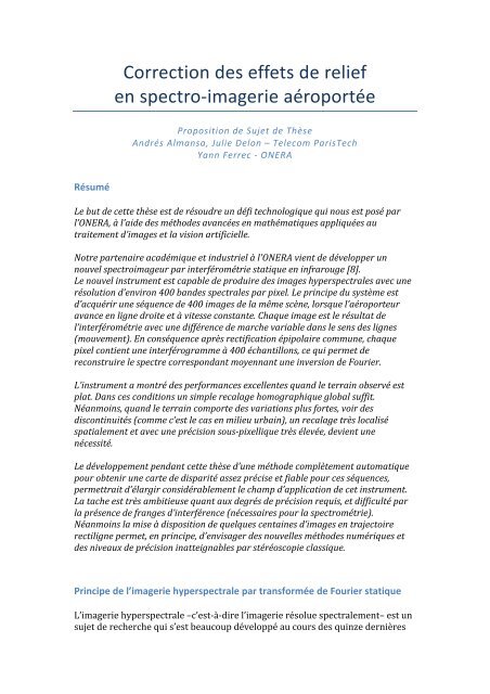
Résumé <br />
Le but <strong>de</strong> cette thèse est <strong>de</strong> résoudre un défi technologique qui nous est posé par <br />
l’ONERA, à l’ai<strong>de</strong> <strong><strong>de</strong>s</strong> métho<strong><strong>de</strong>s</strong> avancées en mathématiques appliquées au <br />
traitement d’images et la vision artificielle. <br />
Notre partenaire académique et industriel à l'ONERA vient <strong>de</strong> développer un <br />
nouvel spectroimageur par interférométrie statique en infrarouge [8]. <br />
Le nouvel instrument est capable <strong>de</strong> produire <strong><strong>de</strong>s</strong> images hyperspectrales avec une <br />
résolution d’environ 400 ban<strong><strong>de</strong>s</strong> spectrales par pixel. Le principe du système est <br />
d’acquérir une séquence <strong>de</strong> 400 images <strong>de</strong> la même scène, lorsque l’aéroporteur <br />
avance en ligne droite et à vitesse constante. Chaque image est le résultat <strong>de</strong> <br />
l’interférométrie avec une différence <strong>de</strong> marche variable dans le sens <strong><strong>de</strong>s</strong> lignes <br />
(mouvement). En conséquence après rectification épipolaire commune, chaque <br />
pixel contient une interférogramme à 400 échantillons, ce qui permet <strong>de</strong> <br />
reconstruire le spectre correspondant moyennant une inversion <strong>de</strong> Fourier. <br />
L’instrument a montré <strong><strong>de</strong>s</strong> performances excellentes quand le terrain observé est <br />
plat. Dans ces conditions un simple recalage homographique global suffit. <br />
Néanmoins, quand le terrain comporte <strong><strong>de</strong>s</strong> variations plus fortes, voir <strong><strong>de</strong>s</strong> <br />
discontinuités (comme c’est le cas en milieu urbain), un recalage très localisé <br />
spatialement et avec une précision sous-‐pixellique très élevée, <strong>de</strong>vient une <br />
nécessité. <br />
Le développement pendant cette thèse d’une métho<strong>de</strong> complètement automatique <br />
pour obtenir une carte <strong>de</strong> disparité assez précise et fiable pour ces séquences, <br />
permettrait d’élargir considérablement le champ d’application <strong>de</strong> cet instrument. <br />
La tache est très ambitieuse quant aux <strong>de</strong>grés <strong>de</strong> précision requis, et difficulté par <br />
la présence <strong>de</strong> franges d’interférence (nécessaires pour la spectrométrie). <br />
Néanmoins la mise à disposition <strong>de</strong> quelques centaines d’images en trajectoire <br />
rectiligne permet, en principe, d’envisager <strong><strong>de</strong>s</strong> nouvelles métho<strong><strong>de</strong>s</strong> numériques et <br />
<strong><strong>de</strong>s</strong> niveaux <strong>de</strong> précision inatteignables par stéréoscopie classique. <br />
Principe <strong>de</strong> l’imagerie hyperspectrale par transformée <strong>de</strong> Fourier statique <br />
L’imagerie hyperspectrale –c’est-‐à-‐dire l’imagerie résolue spectralement– est un <br />
sujet <strong>de</strong> recherche qui s’est beaucoup développé au cours <strong><strong>de</strong>s</strong> quinze <strong>de</strong>rnières
années, tant sur le plan <strong>de</strong> l’analyse <strong><strong>de</strong>s</strong> données que sur celui l’instrumentation, <br />
et aujourd’hui <strong>de</strong> nombreuses sociétés commercialisent <strong><strong>de</strong>s</strong> spectroimageurs <br />
fonctionnant dans le domaine visible. En revanche, les spécificités <strong>de</strong> l’infrarouge <br />
(fort bruit <strong>de</strong> lecture <strong><strong>de</strong>s</strong> détecteurs comparés aux détecteurs visibles, faiblesse <br />
du signal pour la ban<strong>de</strong> [3μm ; 5μm], importance du courant <strong>de</strong> fond pour les <br />
détecteurs sensibles jusqu’à 11μm, etc.) font que le développement <strong>de</strong> spectro-imageurs<br />
infrarouges aéroportés est un exercice technologiquement ardu, au <br />
point qu’actuellement, la France ne dispose pas d’un instrument capable <strong>de</strong> <br />
répondre aux besoins scientifiques et opérationnels. L’Onera a donc été chargé <br />
<strong>de</strong> développer cet instrument, appelé Sieleters. <br />
Celui-‐ci est schématiquement constitué d’une caméra matricielle visant au nadir <br />
au travers d’un interféromètre. Ce <strong>de</strong>rnier agit comme un filtre spectralement <br />
sinusoïdal, dont la pério<strong>de</strong> dépend <strong>de</strong> l’angle d’inci<strong>de</strong>nce et par conséquent <strong>de</strong> la <br />
colonne <strong>de</strong> l’image. Chaque colonne du détecteur est ainsi associée à un état <br />
d’interférences particulier, ce qui se traduit par le fait que les franges <br />
d’interférences se superposent à l’image <strong>de</strong> la scène. <br />
L’appareil est alors placé dans un porteur aéroporté ayant une trajectoire <br />
rectiligne : l’image <strong>de</strong> la scène défile donc par rapport à la matrice <strong>de</strong> détecteurs <br />
et, à chaque fois que l’image a avancé d’une colonne, on déclenche une <br />
acquisition. On dispose ainsi <strong>de</strong> toute une séquence d’images fortement <br />
recouvrantes, à partir <strong>de</strong> laquelle on retrouve le spectre <strong>de</strong> chaque point <strong>de</strong> la <br />
scène, puisque chaque colonne du détecteur est associée à une différence <strong>de</strong> <br />
marche. Ce principe <strong>de</strong> mesure est schématisé par la figure 1, où l’on a mis à <br />
gauche trois images extraites d’une séquence, avec une croix pour marquer un <br />
point fixe au sol. <br />
Fig. 2. (Color online) Figure Principle 1 for obtaining a spectral image using a high étendue Fourier transform hyperspectral imager: first, a<br />
sequence of images are acquired by scanning the scene (only three images are shown on the diagram). These images are then registered,<br />
so that the signal associated to one ground pixel can be retrieved in all the images of the sequence. This signal is the interferogram of the<br />
pixel; its spectrum is <strong>de</strong>duced by a Fourier transform.<br />
dispersive imaging spectrometers, tunable filter<br />
imaging spectrometers, wedge filter imaging spectrometers,<br />
and slitless Fourier transform imaging<br />
• The spectral resolution is limited by the number<br />
of pixels of the focal plane array in the alongtrack<br />
direction. Furthermore, the spectrum is
L’image <strong>de</strong> ce point a été formée à travers différents états d’interférences, et on <br />
peut ainsi reconstituer son interférogramme, puis son spectre par <br />
transformation <strong>de</strong> Fourier. <br />
Importance du recalage <strong><strong>de</strong>s</strong> images : difficulté liée aux variations d’altitu<strong>de</strong> <br />
ou d’élévation <br />
Le recalage <strong>de</strong> toutes les images <strong>de</strong> la séquence est donc une étape clef du <br />
dépouillement <strong><strong>de</strong>s</strong> données, et, pour être le plus exact possible, il doit prendre en <br />
compte les variations d’élévation <strong>de</strong> la scène, qu’elles soient dues au <strong>relief</strong> <br />
intrinsèque du terrain ou aux éléments du sursol (bâtiments, arbres, etc.). <br />
Sur la figure 3, on peut voir l’effet d’une variation d’élévation non prise en <br />
compte : les images ont été recalées selon un modèle global {translation ; <br />
dilatation ; rotation}, et on n’a donc pas tenu compte <strong>de</strong> la moindre vitesse <br />
apparente du toit du bâtiment. Pour un pixel situé au milieu du toit (croix verte), <br />
l’erreur <strong>de</strong> recalage ne se traduit pas par une erreur radiométrique, car le point <br />
reste à l’intérieur d’une zone homogène. Par contre, un pixel situé au bord du toit <br />
sombre (croix rouge) glisse peu à peu vers la faça<strong>de</strong> blanche : l’interférogramme <br />
associé n’est donc pas exploitable, ce qui est particulièrement visible sur sa ligne <br />
<strong>de</strong> base (partie droite <strong>de</strong> la figure 2). <br />
Fig. 12. (Color online) Effects of a change in elevation of the scene. At the beginning, the two pixels are both from the roof (bottom left<br />
image: Figure image 2 number 65). Because of errors in registration, the pixel indicated by a red cross slips gradually toward the front of the house<br />
(top image: image number 435). On the right are the interferograms associated with these two pixels.<br />
by this noise. The second consi<strong>de</strong>ration is that with a<br />
proper stabilization system, which strongly filters<br />
high frequency vibrations, this jitter noise on the interferogram<br />
will be temporally correlated; thus, it<br />
will mainly affect low wavenumbers of the spectrum<br />
and may be concentrated in an out-of-band spectral<br />
domain.<br />
Un modèle numérique d’élévation suffisamment précis est donc nécessaire, <br />
particulièrement en milieu urbain, que ce soit pour corriger les variations <br />
d’élévation ou pour indiquer les zones où l’information n’est pas exploitable. Or, <br />
ce modèle numérique d’élévation n’est pas toujours disponible : il est alors <br />
Elevation variations. The second cause of error<br />
nécessaire <strong>de</strong> retrouver cette information à to partir the intensity <strong><strong>de</strong>s</strong> images variations elles-‐mêmes. in the image. Ceci <br />
est possible, car, du fait <strong>de</strong> l’avancée du porteur, chaque zone <strong>de</strong> la scène a été <br />
vue sous un grand nombre d’angles différents. <br />
in registration comes from the variations of elevation<br />
of the scene. In<strong>de</strong>ed, two ground points at different<br />
elevations will have different apparent speeds for<br />
the imager. Thus a rigid mo<strong>de</strong>l like the one we used<br />
is no more suitable when the scene is not flat. This<br />
effect can be seen on Fig. 12; we have chosen a pixel<br />
at the edge of the roof of a building. This building is<br />
Proposition <strong>de</strong> thèse <br />
viewed by the instrument un<strong>de</strong>r different angles as<br />
the carrier flies over the scene, and on the registered<br />
sequence the roof seems to move with respect to the<br />
ground. Thus, our pixel initially belongs to the roof<br />
but gradually slips to the ground, passing through<br />
the white front of the building. Because of that effect,<br />
the interferogram associated with this pixel is nonsense,<br />
as can be seen on its baseline (Fig. 12).<br />
It is obvious that it is hopeless to retrieve the full<br />
spectrum of parts of the scene that are partially<br />
hid<strong>de</strong>n, like the front of the building on our example.<br />
However, it is possible to take advantage of these<br />
for instance, 5%, the intensity parasitic image is only<br />
0.25% of that of the nominal image. But in our system,<br />
the interferometer acts as a semireflective mirror;<br />
only one parasitic reflection is thus sufficient to<br />
create a parasitic image on the <strong>de</strong>tector (see Fig. 14).<br />
As this unwanted image moves in the opposite direction<br />
compared to the nominal one, it will add noise on<br />
the interferograms, with an amplitu<strong>de</strong> proportional<br />
The basic solution to avoid this problem is to improve<br />
the antireflective layer’s performance. Another<br />
is to use birefringent interferometers, where the nontransmitted<br />
light is absorbed and not reflected, but<br />
even with reflective interferometers, this parasitic<br />
image can be suppressed, by separating the entrance<br />
Le premier objet <strong>de</strong> la thèse sera <strong>de</strong> développer un outil permettant d’estimer à <br />
partir <strong><strong>de</strong>s</strong> images les variations d’élévation <strong>de</strong> la scène. Ceci se fera en adaptant
les outils <strong>de</strong> l’imagerie stéréoscopique « standard » aux spécificités <strong>de</strong> Sieleters, <br />
en particulier la disponibilité <strong>de</strong> plusieurs centaines d’images <strong>de</strong> la même scène. <br />
Il s’agira ensuite d’utiliser les informations ainsi obtenues pour améliorer le <br />
recalage <strong><strong>de</strong>s</strong> images, en affinant à la fois le modèle numérique d’élévation et les <br />
mesures d’attitu<strong>de</strong> du porteur (vitesse, hauteur sol, roulis, lacet et tangage) <br />
fournies par une centrale inertielle. On obtiendra ainsi un outil <strong>de</strong> recalage <br />
robuste et précis. Toutefois, cet outil ne pourra évi<strong>de</strong>mment pas être parfait : le <br />
travail <strong>de</strong> thèse consistera aussi à en évaluer les limites, afin <strong>de</strong> quantifier l’effet <br />
sur les images finales <strong><strong>de</strong>s</strong> défauts <strong>de</strong> recalage. <br />
Pour mener à bien l’ensemble <strong>de</strong> ce travail, le doctorant disposera dès le début <br />
<strong>de</strong> sa thèse d’images expérimentales aéroportées prises avec un instrument <br />
fonctionnant dans le domaine visible, ainsi que <strong><strong>de</strong>s</strong> données d’attitu<strong>de</strong> et <strong>de</strong> <br />
navigation du porteur associées, en attendant la mise en service <strong>de</strong> l’instrument <br />
Sieleters en 2013. Si nécessaire, <strong><strong>de</strong>s</strong> mesures complémentaires pourront être <br />
envisagées. <br />
Méthodologie <br />
Pour répondre au défi technologique <strong>de</strong> l’ONERA, l’étudiant s’appuiera sur <strong><strong>de</strong>s</strong> <br />
développements précé<strong>de</strong>nts <strong>de</strong> l’équipe. Notamment en ce qui concerne la <br />
fiabilité et précision en stéréoscopie [4], que dans notre cas est couplée à la <br />
difficulté additionnelle que les blocs à mettre en correspondance sont <br />
contaminés par <strong><strong>de</strong>s</strong> patterns d’interférométrie différents. Pour une bonne <br />
modélisation mathématique du problème, on tiendra en compte l’irrégularité <br />
induite dans l’échantillonnage <strong><strong>de</strong>s</strong> interférogrammes par la variabilité du terrain, <br />
un problème qui a déjà été étudié par l’équipe en collaboration avec le CNES, <br />
aussi bien dans le cadre <strong>de</strong> l’interférométrie que dans le cadre stéréoscopique <br />
[3]. <br />
Profil du candidat <br />
Le candidat aura une formation en Mathématiques Appliquées au Traitement <br />
d’Images et un goût particulier pour <br />
• la modélisation physique et mathématique <strong><strong>de</strong>s</strong> instruments <strong>de</strong> capture <br />
d'images <br />
• la mise en œuvre informatique d'algorithmes <strong>de</strong> traitement d'images <br />
Bibliographie <br />
[1] Présentation <strong><strong>de</strong>s</strong> instrumentaux CaHyD, Sieleters, et d’autres fruits <strong>de</strong> la <br />
collaboration Onera/Institut d’optique dans le domaine <strong>de</strong> la spectroscopie par <br />
transformée <strong>de</strong> Fourier statique. <br />
http://tele<strong>de</strong>tection.ipgp.fr/sfth/documents/SFTH_5.5_Guerineau.pdf
[2] M. Bryson, M. Johnson-‐Roberson et S. Sukkarieh, « Airborne Smoothing and <br />
Mapping using Vision and Inertial Sensors », 2009 IEEE International Conference <br />
on Robotics and Automation Exemple d’estimation d’un modèle numérique <strong>de</strong> <br />
terrain à partir d’une caméra et d’une central inertielle. <br />
[3] J. Caron, “Irregular Sampling Restoration. Theory and applications to <br />
satellite images and signals.,” Universitée <strong>de</strong> Picardie -‐ S. Durand & A. Almansa <br />
(Dir.), 2012. <br />
http://perso.telecom-‐paristech.fr/~almansa/julien.caron/phd_thesis-‐v4.pdf <br />
[4] N. Sabater, “Reliability and accuracy in stereovision : application to aerial <br />
and satellite high resolution images,” Ecole Normale Supéerieure <strong>de</strong> Cachan -‐ JM. <br />
Morel & A. Almansa (Dir.), 2010. <br />
http://tel.archives-‐ouvertes.fr/tel-‐00505143 <br />
[5] A. Criminisi, S. B. Kang, R. Swaminathan, R. Szeliski, and P. Anandan, <br />
“Extracting layers and analyzing their specular properties using epipolar-‐plane-image<br />
analysis,” Computer Vision and Image Un<strong>de</strong>rstanding, vol. 97, no. 1, pp. <br />
51-‐85, Jan. 2005. <br />
doi:10.1016/j.cviu.2004.06.001 <br />
[6] E. Bughin, “Towards automated, precise & validated vectorisation of <br />
disparity maps in urban satellite stereoscopy,” Ecole Normale Supérieure <strong>de</strong> <br />
Cachan -‐ A. Almansa (Dir.), 2011. <br />
http://tel.archives-‐ouvertes.fr/tel-‐00653875 <br />
[7] J. Delon and B. Rougé, “Small Baseline Stereovision,” Journal of <br />
Mathematical Imaging and Vision, vol. 28, no. 3, pp. 209-‐223, Jul. 2007. <br />
doi:10.1007/s10851-‐007-‐0001-‐1 <br />
[8] Y. Ferrec, J. Taboury, Hervé Sauer, P. Chavel, P. Fournet, C. Coudrain, J. <br />
Deschamps, and J. Primot. “Experimental results from an airborne static Fourier <br />
transform imaging spectrometer,” Applied Optics, 50(30):5894, October 2011. <br />
ISSN 0003-‐ 6935. doi: 10.1364/AO.50.005894.