V600 - V700 - D-HOME-OTIK
V600 - V700 - D-HOME-OTIK
V600 - V700 - D-HOME-OTIK

Create successful ePaper yourself
Turn your PDF publications into a flip-book with our unique Google optimized e-Paper software.
CANCELLI AUTOMATICI<br />
SERIE VER | VER SERIES | SÉRIE VER | BAUREIHE VER | SERIE VER<br />
<strong>V600</strong> - <strong>V700</strong><br />
Documentazione<br />
Tecnica<br />
S87<br />
rev. 0.9<br />
02/2003<br />
© CAME<br />
CANCELLI<br />
AUTOMATICI<br />
119ES87<br />
Automazione con sistema a traino per porte basculanti e sezionali<br />
Automatic traction system for overhead and sectional doors<br />
Automatisme avec systéme "a traction" pour portes basculantes et sectionnels<br />
Schubantriebssistem für Schwing-und Sektionaltore<br />
Automatización con sistema "por arrastre" para puertas basculantes y seccionales<br />
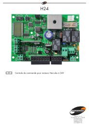
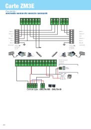
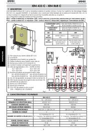
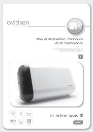
Impianto tipo - Standard installation - Installation type - Standard Montage - Instalaciòn tipo<br />
9 10 7 8<br />
1<br />
230V~<br />
3x1,5<br />
2 3<br />
T RG58<br />
2x1,5<br />
11<br />
4<br />
2x1 6x1,5<br />
5<br />
4x1 2x1<br />
RX<br />
6<br />
TX<br />
5<br />
1. Gruppo VER<br />
2. Quadro comando incorporato<br />
3. Ricevitore radio<br />
4. Pulsantiera da interno<br />
5. Fotocellule di sicurezza<br />
6. Costola a raggi infrarossi<br />
7. Braccio di trasmissione<br />
8. Dispositivo di sblocco<br />
9. Antenna<br />
10. Lampeggiatore<br />
11. Selettore a chiave<br />
1. VER unit<br />
2. Incorporated control<br />
panel<br />
3. Radio receiver<br />
4. Internal pushbutton array<br />
5. Safety photocells<br />
6. Infrared rib<br />
7. Transmission arm<br />
8. Release mechanism<br />
9. Antenna<br />
10. Flashing light<br />
11. Key-operated selector<br />
switch<br />
1. Groupe VER<br />
2. Armoire de commande<br />
incorporée<br />
3. Récepteur radio<br />
4. Poussoirs internes<br />
5. Photocellules de<br />
sécurité<br />
6. Profil de sécurité à<br />
rajons infrarouges<br />
7. Bras de transmission<br />
8. Dispositif de déblocage<br />
9. Antenne<br />
10. Clignotant<br />
11. Sélecteur à clé<br />
1. VER-Antriebsmotor<br />
2. Intergrierte motorsteuerung<br />
3. Funkempfänger<br />
4. Schalteinheit für Innenmontage<br />
5. Lichtschanken<br />
6. Infrarot Sicherheitsleiste<br />
7. Antriebsarm<br />
8. Entriegelungssjstem<br />
9. Antenne<br />
10. Blinkleuche<br />
11. Schlüsselschalter<br />
1. Conjunto VER<br />
2. Cuadro de mando<br />
incorporado<br />
3. Radiorreceptor<br />
4. Botonera interior<br />
5. Fotocélulas de seguridad<br />
6. Protector por infrarrojos<br />
7. Brazo de transmisión<br />
8. Dispositivo de desbloqueo<br />
9. Antena<br />
10. Lámpara intermitente<br />
11. Selector a llave
ITALIANO<br />
Caratteristiche<br />
Descrizione generale:<br />
- Automazione a traino per porte basculanti e sezionali;<br />
- Progettato e costruito interamente dalla CAME Cancelli Automatici S.p.A.,<br />
risponde alle vigenti norme di sicurezza;<br />
- Grado di protezione IP 40;<br />
- Garantito 24 mesi salvo manomissioni.<br />
Versioni:<br />
<strong>V600</strong><br />
Motoriduttore 24V (D.C.) con finecorsa meccanici e con quadro comando<br />
incorporato; alimentazione a 230V a.c. con frequenza 50÷60Hz;<br />
potenza motore 130W max e forza di trazione fino a 500N;<br />
<strong>V700</strong><br />
Motoriduttore 24V (D.C.) con finecorsa meccanici e con quadro comando<br />
incorporato; alimentazione a 230V a.c. con frequenza 50÷60Hz;<br />
potenza motore 260W max e forza di trazione fino a 850N;<br />
Guide di traino:<br />
V0671 - V0674<br />
Gruppo guida con catena L = 3,02 m (V0674 = guida in due metà da<br />
assemblare a 3,02 m);<br />
- per porte basculanti a contrappesi fino a 2,40 m di altezza<br />
- per porte basculanti a molle fino a 2,25 m di altezza<br />
- per porte sezionali* fino a 2,20 m di altezza<br />
V0672<br />
Gruppo guida con catena L = 3,52 m;<br />
- per porte basculanti a molle fino a 2,75 m di altezza<br />
- per porte sezionali* fino a 2,70 m di altezza<br />
V0673<br />
Gruppo guida con catena L = 4,02 m;<br />
- per porte basculanti a molle fino a 3,25 m di altezza<br />
- per porte sezionali* fino a 3,20 m di altezza<br />
V0675 - V0678<br />
Gruppo guida con cinghia L = 3,02 m (V0678 = guida in due metà da<br />
assemblare a 3,02 m);<br />
- per porte basculanti a contrappesi fino a 2,40 m di altezza<br />
- per porte basculanti a molle fino a 2,25 m di altezza<br />
- per porte sezionali* fino a 2,20 m di altezza<br />
V0676<br />
Gruppo guida con cinghia L = 3,52 m;<br />
- per porte basculanti a molle fino a 2,75 m di altezza<br />
- per porte sezionali* fino a 2,70 m di altezza<br />
V0677<br />
Gruppo guida con cinghia L = 4,02 m;<br />
- per porte basculanti a molle fino a 3,25 m di altezza<br />
- per porte sezionali* fino a 3,20 m di altezza<br />
* vedi pagina 5<br />
Accessori di completamento:<br />
V201<br />
Braccio adattatore di trasmissione per porte basculanti a contrappeso<br />
(sostituisce quella in dotazione), vedi pag. 7;<br />
Accessori opzionali:<br />
V0670<br />
Scheda collegamento batterie d'emergenza, completa di supporto per 2<br />
batterie (12V-1,2Ah - ESCLUSE);<br />
V121<br />
Dispositivo di sblocco a cordino e rinvio per il collegamento alla serratura;<br />
V122<br />
Braccio di trasmissione maggiorato per portoni sezionali, vedi pag. 6;<br />
Caratteristiche tecniche:<br />
- Motoriduttore alimentato a 24V in corrente continua (d.c.); cassa del riduttore in<br />
alluminio pressofuso al cui interno opera un sistema di riduzione irreversibile a vite<br />
senza fine e corona elicoidale. La lubrificazione è a grasso fluido permanente.<br />
- Contenitore automazione in ABS con coperchio provvisto di finestra per lampada di<br />
illuminazione diffusa dell'ambiente. Il gruppo è montato e sostenuto dalla guida di<br />
trascinamento.<br />
- Quadro elettrico di comando incorporato.<br />
- Finecorsa a microinterruttori;<br />
- Guida di trascinamento in lamiera zincata profilata a freddo; terminale anteriore di<br />
tensionamento e di fissaggio alla parete; terminale posteriore in ABS di innesto e<br />
sostegno gruppo motore. La guida incorpora il dispositivo di sblocco d'emergenza e<br />
l'aggancio del braccio di trasmissione; nella guida sono previste delle forature per<br />
eventuali attacchi delle staffe supplementari.<br />
- Sistema di traino a catena o a cinghia.<br />
Attenzione! Controllate che le apparecchiature di comando, di sicurezza e gli accessori<br />
siano originali CAME; ciò garantisce e rende l'impianto di facile esecuzione e manutenzione.<br />
ENGLISH<br />
Caracteristics<br />
General description:<br />
- Automatic traction system for overhead and sectional doors;<br />
- Designed and built entirety by CAME Cancelli automatici S.p.A., in full<br />
compliance with current safety standards;<br />
- IP 40 protecting rating;<br />
- Guaranteed for 24 months, unless tampered with by unauthorized personnel.<br />
Versions:<br />
<strong>V600</strong><br />
24V (D.C.) gearmotor with mechanical limit switch and built-in control<br />
board; 230V AC power with 50÷60Hz frequency; 130W max. motor power<br />
and up to 500N in traction power.<br />
<strong>V700</strong><br />
24V (D.C.) gearmotor with mechanical limit switch and built-in control<br />
board; 230V AC power with 50÷60Hz frequency; 260W max. motor power<br />
and up to 850N in traction power.<br />
Sliding rails:<br />
V0671 - V0674<br />
Rail unit with chain L = 3,02 m (V0674 = rail unit in two halves to assemble<br />
at 3.02 m);<br />
- for counterweighted overhead doors up to 2,40 m height<br />
- for spring-balanced overhead doors up to 2,25 m height<br />
- for sectional doors* up to 2,20 m height<br />
V0672<br />
Rail unit with chain L = 3,52 m;<br />
- for spring-balanced overhead doors up to 2,75 m height<br />
- for sectional doors* up to 2,70 m height<br />
V0673<br />
Rail unit with chain L = 4,02 m;<br />
- for spring-balanced overhead doors up to 3,25 m height<br />
- for sectional doors* up to 3,20 m height<br />
V0675 - V0678<br />
Rail unit with belt L = 3,02 m (V0678 = rail unit in two halves to assemble<br />
at 3.02 m);<br />
- for counterweighted overhead doors up to 2,40 m height<br />
- for spring-balanced overhead doors up to 2,25 m height<br />
- for sectional doors* up to 2,20 m height<br />
V0676<br />
Rail unit with belt L = 3,52 m;<br />
- for spring-balanced overhead doors up to 2,75 m height<br />
- for sectional doors* up to 2,70 m height<br />
V0677<br />
Rail unit with belt L = 4,02 m;<br />
- for spring-balanced overhead doors up to 3,25 m height<br />
- for sectional doors* up to 3,20 m height<br />
* see page 5<br />
Accessories:<br />
V201<br />
Transmission adapter arm for counterweighted overhead doors (it substitutes<br />
the arm supplied), see pg. 7;<br />
Optional accessories:<br />
V0670<br />
Emergency battery connection card with support for 2 batteries (12V-<br />
1,2Ah - ESCLUSE);<br />
V121<br />
Cable release device and transmission for connection to the lock;<br />
V122<br />
Improved transmission arm for sectional gates, see pg. 6;<br />
Technical specifications:<br />
- 24V DC gearmotor; reduction gear unit housed in a die-cast aluminium casing. The<br />
unit features an irreversible reduction gear with worm screw and helicoidal. Permanently<br />
lubricated with liquid grease.<br />
- ABS automation container and cover with window for lamp to illuminate the area. The<br />
unit is mounted on and supported by the sliding rail.<br />
- Built-in electric control panel.<br />
- Microswitch end-stop;<br />
- Galvanised cold-formed plate sliding rail; front tensioning and fastening wall terminal;<br />
ABS back motor unit support and connector terminal. The rail has a built-in emergency<br />
release device and the transmission arm’s hook; the rail has holes for possible connection<br />
of additional brackets.<br />
- Chain or belt sliding system.<br />
Attention! to insure easy installation and conformance with current safety, norms, we<br />
raccomend installation of CAME safety and control accessories.<br />
2
FRANÇAIS<br />
Caractéristiques<br />
Description génèralés:<br />
- Automatisme avec sistéme "a traction" pour portes basculantes et sectionnels.<br />
- Il a été entièrement concu et construit par la Société CAME Cancelli<br />
Automatici S.p.A., conformément aux normes de sécurité en vigueur;<br />
- Degré de protection IP 40.<br />
- Il est garanti 24 mois sauf en cas d'altérations.<br />
Versions:<br />
<strong>V600</strong><br />
Motoréducteur 24V (C.C.) avec butées de fin de course mécaniques et<br />
tableau de commande incorporé; alimentation en 230V a.c. avec fréquence<br />
50÷60Hz; puissance du moteur 130W max. et force de traction<br />
jusqu’à 500N;<br />
<strong>V700</strong><br />
Motoréducteur 24V (C.C.) avec butées de fin de course mécaniques et<br />
tableau de commande incorporé; alimentation en 230V a.c. avec fréquence<br />
50÷60Hz; puissance du moteur 260W max. et force de traction<br />
jusqu’à 850N;<br />
Guides de traction:<br />
V0671 - V0674<br />
Groupe guide avec chaîne L = 3,02 m (V0674 = groupe guide en deux<br />
moitiés à assembler à 3,02 m);<br />
- pour portes basculantes à contrepoids jusqu’à 2,40 m de haut<br />
- pour portes basculantes à ressorts jusqu’à 2,25 m de haut<br />
- pour portes sectionnelles* jusqu’à 2,20 m de haut<br />
V0672<br />
Groupe guide avec chaîne L = 3,52 m;<br />
- pour portes basculantes à ressorts jusqu’à 2,75 m de haut<br />
- pour portes sectionnelles* jusqu’à 2,70 m de haut<br />
V0673<br />
Groupe guide avec chaîne L = 4,02 m;<br />
- pour portes basculantes à ressorts jusqu’à 3,25 m de haut<br />
- pour portes sectionnelles* jusqu’à 3,20 m de haut<br />
V0675 - V0678<br />
Groupe guide avec courroie L = 3,02 m (V0678 = groupe guide en deux<br />
moitiés à assembler à 3,02 m);<br />
- pour portes basculantes à contrepoids jusqu’à 2,40 m de haut<br />
- pour portes basculantes à ressorts jusqu’à 2,25 m de haut<br />
- pour portes sectionnelles* jusqu’à 2,20 m de haut<br />
V0676<br />
Groupe guide avec courroie L = 3,52 m;<br />
- pour portes basculantes à ressorts jusqu’à 2,75 m de haut<br />
- pour portes sectionnelles* jusqu’à 2,70 m de haut<br />
V0677<br />
Groupe guide avec courroie L = 4,02 m;<br />
- pour portes basculantes à ressorts jusqu’à 3,25 m de haut<br />
- pour portes sectionnelles* jusqu’à 3,20 m de haut<br />
* voir page 5<br />
Accessoires complémentaires:<br />
V201<br />
Bras adaptateur de transmission pour portes basculantes à contrepoids<br />
(remplace celui fourni de série), voir page 7;<br />
Accessoires en option:<br />
V0670<br />
Carte de branchement batteries d’urgence avec support pour 2 batteries<br />
(12V-1,2 Ah – NON COMPRISES);<br />
V121<br />
Dispositif de déblocage et de renvoi à cordon pour le branchement à la<br />
serrure;<br />
V122<br />
Bras de transmission plus grand pour portes sectionnelles, voir p. 6;<br />
Caractéristiques techniques:<br />
- Motoréducteur alimenté en 24V en courant continu (d.c.); coffre du réducteur réalisé<br />
en aluminium moulé sous pression. A l'intérieur agi' un système de réduction irréversible<br />
à vis sans fin et couronne hélicoidale. Lubrification permanente par graisse fluide.<br />
- Boîtier automatisme en ABS avec couvercle muni d’une fenêtre pour lampe d’éclairage<br />
diffuse du local. Le groupe est monté et soutenu par le guide d’entraînement.<br />
- Armoire électrique de commande incorporé.<br />
- Microinterrupteurs de fin de course;<br />
- Guide d’entraînement en tôle zinguée profilée à froid; élément terminal avant de<br />
tension et de fixation au mur; élément terminal arrière de raccord et de soutien du<br />
groupe du moteur en ABS. Le guide comprend le dispositif de déblocage d’urgence et<br />
d’accrochage du bras de transmission; des trous ont été prévus dans le guide pour les<br />
raccords éventuels des brides supplémentaires.<br />
- Système de traction par chaîne ou par courroie.<br />
Attention! Vérifiez que l'appareillage de commande, de sécurité et les accessoires sont<br />
des produits originaux CAME afin de garantir l'installation et d'en faciliter le montage<br />
et l'entretien.<br />
DEUTSCH<br />
Allgemeine merkmale<br />
Beschreibung:<br />
- Schubantriebssistem für Kipptoren und Sektionaltoren.<br />
- Vollständig von der CAME Cancelli Automatici S.p.A. gemäß geltender<br />
Sicherheilsnormen entwickelt und hergestellt.<br />
- Schutzklasse IP 40;<br />
- Garantie: 24 Monate, vorbehaltlich unsachgemäßer Handhabung und<br />
Montage.<br />
Ausführungen:<br />
<strong>V600</strong><br />
Getriebemotor 24V (Gleichstrom) mit mechanischen Endanschlägen<br />
und eingebauter Schalttafel; Speisung 230V WS mit Frequenz 50-60 Hz;<br />
max. Motorleistung 130W und Zugkraft bis zu 500N;<br />
<strong>V700</strong><br />
Getriebemotor 24V (Gleichstrom) mit mechanischen Endanschlägen<br />
und eingebauter Schalttafel; Speisung 230V WS mit Frequenz 50-60 Hz;<br />
max. Motorleistung 260W und Zugkraft bis zu 850N;<br />
Antriebsgehäuse:<br />
V0671 - V0674<br />
Steuergruppe mit Kette L = 3.02 m (V0674 = Steuergruppe in zwei Hälften<br />
auf 3.02 m zusammenzusetzen);<br />
- für Gegengewicht-Kipptoren bis zu einer Höhe von 2.40 m<br />
- für Ausgleichsfeder-Kipptoren bis zu einer Höhe von 2.25 m<br />
- für Sektionaltoren* bis zu einer Höhe von 2,20 m<br />
V0672<br />
Steuergruppe mit Kette L = 3.52 m;<br />
- für Ausgleichsfeder-Kipptoren bis zu einer Höhe von 2.75 m<br />
- für Sektionaltoren* bis zu einer Höhe von 2,70 m<br />
V0673<br />
Steuergruppe mit Kette L = 4.02 m;<br />
- für Ausgleichsfeder-Kipptoren bis zu einer Höhe von 3.25 m<br />
- für Sektionaltoren* bis zu einer Höhe von 3,20 m<br />
V0675 - V0678<br />
Steuergruppe mit Riemen L = 3.02 m (V0678 = Steuergruppe in zwei<br />
Hälften auf 3.02 m zusammenzusetzen);<br />
- für Gegengewicht-Kipptoren bis zu einer Höhe von 2.40 m<br />
- für Ausgleichsfeder-Kipptoren bis zu einer Höhe von 2.25 m<br />
- für Sektionaltoren* bis zu einer Höhe von 2,20 m<br />
V0676<br />
Steuergruppe mit Riemen L = 3.52 m;<br />
- für Ausgleichsfeder-Kipptoren bis zu einer Höhe von 2.75 m<br />
- für Sektionaltoren* bis zu einer Höhe von 2,70 m<br />
V0677<br />
Steuergruppe mit Riemen L = 4.02 m;<br />
- für Ausgleichsfeder-Kipptoren bis zu einer Höhe von 3.25 m<br />
- für Sektionaltoren* bis zu einer Höhe von 3,20 m<br />
* siehe Seite 5<br />
Zusätzliche Zubehörteile:<br />
V201<br />
Anpassungs-Antriebsarm für Gegengewicht-Kipptoren (ersetzt den zur<br />
Ausstattung gehörenden Arm), siehe Seite 7;<br />
Optionale Zubehörteile:<br />
V0670<br />
Anschlußkarte für Notbatterien mit Halterung für 2 Batterien (12V-1,2Ah<br />
– AUSGESCHLOSSEN);<br />
V121<br />
Entsperrvorrichtung mit Schnur und Umlenkung zur Verbindung mit<br />
dem Schloß;<br />
V122<br />
Übergroßer Antriebsarm für Sektionaltoren, siehe Seite 6;<br />
Technische Eigenschaften:<br />
- In Gleichstrom (d.c.) bei 24V gespeister Getriebemotor; Untersetzungsgetriebe in<br />
Aluminium-druckgußgehäuse. Irreversibles Schnecken/Schrägzahnraduntersetzungsgetriebe.<br />
Dauerschmierung mirreis flüssigem Schmiermittel.<br />
- Kasten für die Automatik in ABS mit einem mit einem Fenster versehenen Deckel für<br />
die Lampe zur Beleuchtung der Umgebung. Die Gruppe ist montiert und durch den<br />
Verbindungsträger abgestützt.<br />
- Eingebaute Schalttafel.<br />
- Endanschlag mit Mikroschaltern.<br />
- Verbindungsträger aus kaltgeformten Zinkblech; vorderes Endstück zum Spannen<br />
und zur Wandbefestigung; hinteres Endstück in ABS zur Kupplung und Halterung der<br />
Motorgruppe. In der Steuergruppe ist die Notentsperrvorrichtung und die Kupplung<br />
des Antriebsarms eingebaut; in der Steuergruppe sind Bohrungen für die eventuellen<br />
Anschlüsse von zusätzlichen Bügeln vorgesehen.<br />
Zugsystem durch Kette oder Riemen.<br />
Achtung! Wir empfehlen original CAME-Schalt- und -Sicherheitsvorrichtungen mit<br />
entsprechendem Zubehör zu montieren, um die einwandfreie Montage und die<br />
problemlose Wartung der Anlage zu gewährleisten.<br />
3
ESPAÑOL<br />
Caracteristicas<br />
Descripción generales:<br />
- Automatización con sistema "por arrastre" para puertas basculantes<br />
y seccionales.<br />
- Diseñado y fabricado enteramente por CAME Cancelli Automatici<br />
S.p.A., cumple con las normas de seguridad vigentes.<br />
- Grado de protección IP 40.<br />
- Garantizado 24 meses, salvo manipulaciones.<br />
Versiones:<br />
<strong>V600</strong><br />
Motorreductor 24V (D.C.) con finales de carrera mecánicos y cuadro<br />
de mando incorporado; alimentación a 230V c.a. con frecuencia de<br />
50÷60 Hz; potencia motor 130W máx y fuerza de tracción hasta 500N;<br />
<strong>V700</strong><br />
Motorreductor 24V (D.C.) con finales de carrera mecánicos y cuadro<br />
de mando incorporado; alimentación a 230V c.a. con frecuencia de<br />
50÷60 Hz; potencia motor 260W máx y fuerza de tracción hasta 850N;<br />
Guías de empuje:<br />
V0671 - V0674<br />
Grupo de guía con cadena L = 3,02 m (V0674 = grupo de guía en dos<br />
mitades a ensamblar a 3,02 m);<br />
- para puertas basculantes por contrapesos hasta 2,40 m de altura<br />
- para puertas baculantes por resorte hasta 2,25 m de altura<br />
- para puertas seccionales* hasta 2,20 m de altura<br />
V0672<br />
Grupo de guía con cadena L = 3,52 m;<br />
- para puertas baculantes por resorte hasta 2,75 m de altura<br />
- para puertas seccionales* hasta 2,70 m de altura<br />
V0673<br />
Grupo de guía con cadena L = 4,02 m;<br />
- para puertas baculantes por resorte hasta 3,25 m de altura<br />
- para puertas seccionales* hasta 3,20 m de altura<br />
Accesorios de completamiento:<br />
V201<br />
Brazo adaptador de transmisión para puertas basculantes por<br />
contrapesos (sustituye la de serie), véase pág. 7;<br />
Accesorios opcionales:<br />
V0670<br />
Tarjeta de conexión baterías de emergencia, completa con soporte<br />
para 2 baterías (12V-1,2Ah - EXCLUIDAS);<br />
V121<br />
Dispositivo de desbloqueo con cable y transmisión para la conexión a<br />
la cerradura;<br />
V122<br />
Brazo de transmisión extragrande para puertas seccionales, véase<br />
pág.6;<br />
Características técnicas:<br />
- Motorreductor alimentado a 24V en corriente continua (c.c.); caja del<br />
reductor de aluminio fundido. En su interior obra un sistema de<br />
reducción irreversible por tornillo sin fin y corona hellcoidal. La<br />
lubricación es permanente, por grasa fluida.<br />
- Contenedor de automatización en ABS con tapa dotada de ventana con<br />
lámpara de alumbrado difuso del ambiente. El grupo está montado y<br />
sostenido por la guía de arrastre.<br />
- Cuadro eléctrico de mando incorporado.<br />
- Final de carrera por microinterruptores;<br />
- Guía de arrastre en chapa galvanizada perfilada en frío; terminal anterior<br />
de tensado y de fijación en la pared; terminal posterior en ABS de<br />
acoplamiento y sostén del grupo motor. La guía incorpora el dispositivo de<br />
desbloqueo de emergencia y el enganche del brazo de transmisión; en la<br />
guía se prevén perforaciones para eventuales enganches de abrazaderas<br />
suplementarias.<br />
- Sistema de empuje por cadena o por correa.<br />
Atención! Comprobar que los equipos de mando, de seguridad y los<br />
acesorios sean originales CAME; lo cual garantiza y facilita el uso y<br />
mantenimiento del aparato.<br />
V0675 - V0678<br />
Grupo de guía con correa L = 3,02 m (V0678 = grupo de guía en dos<br />
mitades a ensamblar a 3,02 m);<br />
- para puertas basculantes por contrapesos hasta 2,40 m de altura<br />
- para puertas baculantes por resorte hasta 2,25 m de altura<br />
- para puertas seccionales* hasta 2,20 m de altura<br />
V0676<br />
Grupo de guía con correa L = 3,52 m;<br />
- para puertas baculantes por resorte hasta 2,75 m de altura<br />
- para puertas seccionales* hasta 2,70 m de altura<br />
V0677<br />
Grupo de guía con correa L = 4,02 m;<br />
- para puertas baculantes por resorte hasta 3,25 m de altura<br />
- para puertas seccionales* hasta 3,20 m de altura<br />
* véase página 5<br />
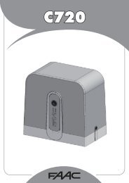
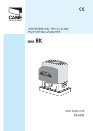
CARATTERISTICHE TECNICHE MOTORIDUTTORE // GEAR MOTOR TECNICHAL CARACTERISTICS<br />
CARACTÉRISTIQUES TECHNIQUES MOTORÉDUCTEUR // GETRIEBEMOTOR TECNISCHEDATEN // CARACTERÍSTICAS TÉCNICAS MOTORREDUCTOR<br />
Motoriduttore<br />
Gear<br />
motor<br />
Motoréducteur<br />
Getriebemotor<br />
Motorreductor<br />
<strong>V600</strong><br />
<strong>V700</strong><br />
Peso<br />
Weight<br />
Poids<br />
Gewicht<br />
Peso<br />
Alimentazion<br />
e<br />
Power<br />
Supply<br />
Alimentatio<br />
n<br />
Netzspannun<br />
g<br />
Alimentació<br />
n<br />
Assorbimento<br />
motore<br />
Motor<br />
absorption<br />
Absorption<br />
moteur<br />
Motor-Stomaufnahm<br />
e<br />
Absorción<br />
motor<br />
Potenza<br />
max<br />
Max<br />
power<br />
Puissance<br />
max<br />
Max<br />
Leistung<br />
Potencia<br />
max<br />
Intermittenza<br />
di lavoro<br />
Duty<br />
cycle<br />
Intermittence<br />
de travail<br />
Einschaltdaue<br />
r<br />
Intermitencia<br />
de trabajo<br />
Forza<br />
di trazione<br />
Traction<br />
force<br />
Force<br />
de traction<br />
Zugkraft<br />
Fuerza<br />
de arrastre<br />
5,7 Kg<br />
6A max 130W<br />
500N<br />
230V a.c.<br />
50 %<br />
5,9<br />
Kg<br />
11A max<br />
260W<br />
850N<br />
Velocità media<br />
Average speed<br />
Vitesse moyenne<br />
Durchschnittsge s<br />
Velocidad media<br />
6 m/min<br />
4
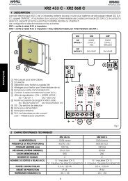
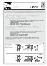
ESEMPI DI APPLICAZIONE // EXAMPLES OF APPLICATIONS // EXEMPLES ES D'APPLICATIONS //<br />
INSTALLATIONSBEISPIELE // EJEMPLOS DE APLICACIONES<br />
A<br />
H<br />
PORTA BASCULANTE A CONTRAPPESI, tipo a corsa verticale<br />
debordante e a parziale rientranza<br />
COUNTERWEIGHTED OVERHEAD DOOR, vertical stroke outward and<br />
partially inward entry type<br />
PORTE BASCULANTE Á CONTREPOIDS, type à course verticale<br />
débordante et à retrait partielle<br />
GEGENGEWICHT-KIPPTOREN, Heraustragende-Vertikalbewegung<br />
und partial Ausparung Typ<br />
PUERTA BASCULANTE POR CONTRAPESOS, tipo a recorrido<br />
vertical desbordante y a entrada parcial<br />
B<br />
H<br />
PORTA BASCULANTE A MOLLE, tipo a corsa verticale<br />
debordante e a totale rientranza<br />
SPRING-BALANCED OVERHEAD DOOR, spring balanced, vertical<br />
stroke outward and totally inward entry type<br />
PORTE BASCULANTE Á RESSORTS, type à course verticale<br />
débordante et à retrait totale<br />
AUSGLEICHSFEDER-KIPPTOREN, Heraustragende-<br />
Vertikalbewegung und völlig Ausparung Typ<br />
PUERTA BASCULANTE POR RESORTE, tipo a recorrido vertical<br />
desbordante y a entrada total<br />
CA<br />
PORTA SEZIONALE<br />
SECTIONAL DOOR<br />
PORTE SECTIONNELLE<br />
SEKTIONALTOR<br />
PUERTA SECCIONAL<br />
H<br />
H - 100mm<br />
a singola guida<br />
single sliding rail<br />
à une seule guide<br />
EinzelVerbindungsträger<br />
a guía individual<br />
H<br />
a doppia guida<br />
double sliding rail<br />
à double guide<br />
DoppelVerbindungsträger<br />
a guía doble<br />
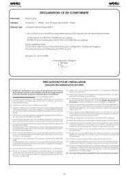
MISURE D'INGOMBRO // EXTERNAL DIMENSIONS // MEASURES D'ENCOMBRENT // ABMESSUNGEN // DIMENSIONES<br />
Uscita cavi<br />
Cable exit<br />
Sortie cables<br />
Netzkabeleingang<br />
Salida de los cables<br />
540 max*<br />
140 18<br />
400 212<br />
* Per altezze superiori a tale valore, prevedere dei tiranti o staffe supplementari<br />
For heights exceding 540 mm., it is necessary to use additional brackets or struts<br />
Pour des hauteurs superieures a cette valeur, prevoir des tirants ou des etriers supplementaires<br />
Bei Höhen, die obiges Maß überschreiten zusätzliche Schubstangen oder Bügel montieren<br />
Para las alturas mayores que esta medida, se deben utilizar unos tirantes o soportes adicionales<br />
PRESA E SPINA DI ALIMENTAZIONE // POWER SUPPLY PLUG AND OUTLET // PRISE ET FICHE D'ALIMENTATION //<br />
STECK KONTAKTE FÜR BETRIEBSSPANNUNG // PRENSA Y ENCHUFE DE ALIMENTACIÓN<br />
USE ONLY 250V FUSES<br />
N<br />
L<br />
5
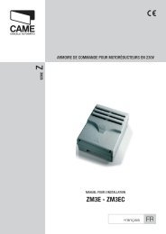
MONTAGGIO DEL GRUPPO // UNIT ASSEMBLY // MONTAGE DU GROUPE // MONTAGE DER GRUPPE // MONTAJE DEL GRUPO<br />
ITALIANO<br />
ENGLISH<br />
FRANÇAIS<br />
DEUTSCH<br />
ESPAÑOL<br />
PREDISPOSIZIONE<br />
GUIDA DI TRASMISSIONE<br />
PREARRANGEMENT OF<br />
TRANSMISSION RAIL<br />
PRÉPARATION GUIDE<br />
DE TRANSMISSION<br />
VORBEREITUNGS DER<br />
ANTRIEBSGRUPPE<br />
PREDISPOSICIÓN GUÍA<br />
DE TRANSMISIÓN<br />
- Fissare la staffa sul terminale<br />
anteriore della guida<br />
di trasmissione con le viti in<br />
dotazione;<br />
- Fasten the bracket to the<br />
transmission guide’s front<br />
terminal with the screws<br />
provided;<br />
- Fixer la bride sur l’élément<br />
terminal avant du guide de<br />
transmission avec les vis<br />
fournies de série;<br />
- Mit den zur Ausstattung<br />
gehörenden Schrauben den<br />
Bügel am vorderen Endstück<br />
der Antriebsgruppe<br />
befestigen;<br />
- Fijar la abrazadera en el<br />
terminal anterior de la guía<br />
de transmisión con los tornillos<br />
de serie;<br />
M6<br />
M6x20<br />
FISSAGGIO GUIDA DI<br />
TRASMISSIONE<br />
TRANSMISSION RAIL<br />
FASTENING<br />
FIXATION GUIDE DE<br />
TRANSMISSION<br />
BEFESTIGUNG DER<br />
ANTRIEBSGRUPPE<br />
FIJACIÓN GUÍA DE<br />
TRANSMISIÓN<br />
- Fissare la guida di trasmissione<br />
nel seguente<br />
modo:<br />
a) per porte sezionali<br />
tipo C (vedi rif. pag. 5), fissare<br />
la staffa direttamente<br />
sopra il palo-molla (figura<br />
1), usando tasselli e viti<br />
adeguati; se la distanza fra<br />
il palo-molla e la battuta superiore<br />
del portone è compresa<br />
tra 30 e 60 cm,<br />
applicare il braccio V122<br />
(consultare la documentazione<br />
tecnica allegata all'accessorio);<br />
- Fasten the transmission<br />
rail in the following manner:<br />
a) for sectional doors<br />
C-type (see ref. p.5), fasten<br />
the bracket directly<br />
over the spring-release<br />
coiling shaft using adequate<br />
dowels and screws; if the<br />
distance between the coiling<br />
shaft and the gate’s upper<br />
ledge is between 30<br />
and 60 cm, apply the V122<br />
arm (read the technical<br />
documentation provided<br />
with the accessory);<br />
- Fixer le guide de transmission<br />
de la façon suivante:<br />
a) pour portes sectionnelle<br />
type C (voir réf. page<br />
5), fixer la bride directement<br />
au-dessus de l’axe à<br />
ressort, à l’aide de chevilles<br />
et de vis appropriées; appliquer<br />
le bras V122 si la<br />
distance entre l’axe à ressort<br />
et la butée supérieure<br />
du portail est comprise entre<br />
30 et 60 cm (consulter<br />
la documentation technique<br />
jointe à l’accessoire);<br />
- Die Antriebsgruppe ist wie<br />
folgt zu befestigen:<br />
a) für Sektionaltoren<br />
Typ C (siehe S. 5) den Bügel<br />
direkt an der Wand<br />
oberhalb der mit einer<br />
Sprungfeder umwickelten<br />
Welle befestigen. Dazu<br />
sind angemessene Dübel<br />
und Schrauben zu benutzen;<br />
falls der Abstand<br />
zwischen der Welle und<br />
dem oberen Toranschlag<br />
zwischen 30 und 60 cm<br />
liegt, ist der Arm V122<br />
anzubringen.(die technische<br />
dem Zubehörteil anliegende<br />
technische Dokumentation<br />
zu Rate ziehen);<br />
- Fijar la guía de transmisión<br />
de la siguiente manera:<br />
a) para puertas seccional<br />
tipo C (véase ref. pág.<br />
5), fijar la abrazadera directamente<br />
arriba de la barraresorte,<br />
usando tarugos y<br />
tornillos adecuados; si la<br />
distancia entre la barra-resorte<br />
y el punto de contacto<br />
superior de la puerta está<br />
comprendida entre 30 y 60<br />
cm, aplicar el brazo V122<br />
(consultar la documentación<br />
técnica anexa al accesorio);<br />
Fig./Abb. 1<br />
= =<br />
20 á 30 mm<br />
Palo-molla<br />
Spring-bar<br />
Barre du ressort<br />
Federbügel<br />
Barra-resorte<br />
Battuta superiore della porta<br />
Upper edge of door<br />
Point de fermeture supérieur de la porte<br />
Obere Torkante<br />
Punto de contacto superior de la puerta<br />
V122<br />
30 ÷ 60 cm<br />
Palo-molla<br />
Spring-bar<br />
Barre du ressort<br />
Federbügel<br />
Barra-resorte<br />
6
) per porte basculanti<br />
tipo A-B (vedi rif. pag. 5),<br />
verificare il punto massimo<br />
di scorrimento dell'anta<br />
(fig.2) e fissare di conseguenza<br />
in altezza la staffa<br />
con viti o rivetti adeguati.<br />
N.B.: per porte basculanti a<br />
contrappesi debordanti, bisogna<br />
utilizzare il braccio<br />
adattatore V201 (consultare<br />
la documentazione tecnica<br />
allegata all'accessorio).<br />
b) for A-B-type overhead<br />
doors (see ref. p.5), verify<br />
the maximum door sliding<br />
point (fig.2) and consequently<br />
fasten the bracket<br />
on high with adequate<br />
screws or rivets.<br />
N.B.: for counterweighted<br />
overhead doors, partial entry,<br />
it is necessary to use<br />
the adapter arm V201 (read<br />
the technical documentation<br />
provided with the accessory).<br />
b) pour portes basculantes<br />
type A-B (voir réf.<br />
page 5), contrôler le point<br />
maximum de coulissement<br />
de la porte (fig.2) et fixer<br />
proportionnellement la bride<br />
en hauteur avec des vis<br />
ou des rivets appropriés.<br />
N.B.: utiliser le bras d'adaptation<br />
V201 pour porte basculante<br />
á contrepoids, débordante,<br />
(consulter la documentation<br />
jointe à l’accessoire).<br />
b) für Kipptoren Typ A-<br />
B (siehe S. 5) den maximalen<br />
Gleitpunkt des Torflügels<br />
(Abb.2) feststellen und<br />
aut der dementsprechenden<br />
Höhe den Bügel mit angemessenen<br />
Schrauben<br />
oder Nieten befestigen.<br />
Bitte beachten: Für Gegengewichtstor<br />
wird der Paßarm<br />
V201 benötigt (die die<br />
Zubehörteil anliegende<br />
technische Dokumentation<br />
zu Rate ziehen).<br />
b) para puertas basculantes<br />
tipo A-B (véase ref.<br />
pág. 5), verificar el punto<br />
máximo de deslizamiento<br />
de la puerta (fig.2) y de consecuencia<br />
fijar la altura de<br />
la abrazadera con tornillos<br />
o remaches apropiados.<br />
Nota: para puerta basculante<br />
a contrapeso de entrada<br />
parcial, hay que utilizar el<br />
brazo adaptador V201 (consultar<br />
la documentación<br />
técnica anexa al accesorio).<br />
Fig./Abb. 2<br />
10 ÷ 20 mm<br />
= =<br />
H = 2.4 m max.<br />
V201<br />
7
- Sollevare e disporre orizzontalmente<br />
la guida per rilevare<br />
la distanza dal soffitto;<br />
di conseguenza, fissare<br />
al terminale posteriore<br />
della guida gli angolari oppure<br />
le staffe di fissaggio in<br />
dotazione (tagliando l'eventuale<br />
eccedenza). N.B. nella<br />
guida di trasmissione<br />
sono predisposti 3 fori ø7<br />
per ulteriori fissaggi nel<br />
caso si desideri rinforzare<br />
il gruppo.<br />
- Sollevare e fissare la guida<br />
di trasmissione al soffitto<br />
livellandola.<br />
- Predisporre la traccia per<br />
i collegamenti elettrici.<br />
- Raise and set the guide<br />
horizontally to establish the<br />
distance from the ceiling;<br />
then fasten the angle sections<br />
or fastening brackets<br />
provided (cutting off any excess<br />
part) to the rail’s back<br />
terminal. N.B. the transmission<br />
guide has three ø7<br />
holes for further fastening<br />
should it prove necessary<br />
to reinforce the unit.<br />
- Lift, level and fix the rail to<br />
the ceiling.<br />
- Prepare the chase for<br />
electric wiring.<br />
- Soulever et disposer le<br />
guide horizontalement pour<br />
relever la distance du plafond,<br />
fixer ensuite les cornières<br />
ou les brides de fixation<br />
fournies de série (en<br />
coupant la partie en trop<br />
éventuelle) à l’élément terminal<br />
arrière du guide.<br />
N.B.: 3 trous ø7 sont prévus<br />
dans le guide de transmission<br />
pour fixer d’autres<br />
éléments afin de renforcer<br />
le groupe.<br />
- Soulever, fixer et niveler<br />
la guide de transmission an<br />
plafond.<br />
- Prévoir la place pour les<br />
branchements électriques;<br />
Zur Feststellung des Dekkenabstands,<br />
die Antriebsschiene<br />
anheben und horizontal<br />
anbringen; am hinteren<br />
Endstück die Winkelprofile<br />
oder die zur Ausstattung<br />
gehörenden Befestigungsbügel<br />
(den überstehenden<br />
Teil eventuell abschneiden)<br />
befestigen. N.B.<br />
Zur eventuellen Verstärkung<br />
der Gruppe sind am<br />
Verbindungsträger 3 Löcher<br />
ø7 für weitere Befestigungen<br />
vorgesehen.<br />
- Die Antriebsschiene anheben<br />
und rechtwinklig zur<br />
Wand an der Decke befestigen.<br />
- Den Elektrokabelkanal<br />
vorbereiten.<br />
- Levantar y colocar horizontalmente<br />
la guía para<br />
detectar la distancia hasta<br />
el techo; de consecuencia<br />
fijar al terminal posterior de<br />
la guía los angulares o las<br />
abrazaderas de fijación de<br />
serie (cortando la parte<br />
eventualmente excedente).<br />
Nota: en la guía de transmisión<br />
hay 3 agujeros ø7<br />
para otras fijaciones en el<br />
caso se desee reforzar el<br />
grupo.<br />
- Levante el riel, nivelelo y<br />
fije al techo.<br />
- Predisponer las huellas<br />
para las conexiones eléctricas.<br />
Livella<br />
Level<br />
Niveau à bulle<br />
im Wasser<br />
Nivel<br />
M6<br />
M6x14<br />
M6x14<br />
Ø7<br />
8
FISSAGGIO LEVE DI<br />
TRAINO<br />
SLIDING LEVER<br />
FASTENING<br />
FIXATION LEVIERS DE<br />
TRACTION<br />
BEFESTIGUNG DER<br />
ZUGHEBEL<br />
FIJACIÓN DE LAS<br />
PALANCAS DE EMPUJE<br />
- Fissare centralmente il<br />
braccio di trasmissione al<br />
traverso superiore della<br />
porta con i rivetti in dotazione<br />
(o eventuali viti);<br />
- Montare la manopola di<br />
sblocco avvitandola sul<br />
nottolino del gruppo sblocco<br />
premontato e fissarla<br />
nella posizione consigliata<br />
con il controdado;<br />
- Spostare il pattino di scorrimento<br />
e agganciarlo al<br />
braccio di trasmissione,<br />
previo smontaggio della vite<br />
premontata.<br />
N.B.: nel caso di utilizzo del<br />
braccio adattatore (V201)<br />
agganciare il carrello al pattino<br />
di scorrimento.<br />
- Centrally fix the transmission<br />
arm to the door’s upper<br />
crosspiece with the rivets<br />
provided (or possible<br />
screws);<br />
- Mount the unlocking handle<br />
by screwing it to the preassembled<br />
unlocking unit’s<br />
revolving plug and fasten it<br />
in the recommended position<br />
with the lock nut;<br />
- Move the sliding runner<br />
and hook it to the transmission<br />
arm after removing the<br />
preset screw.<br />
N.B.: if the adapter arm<br />
(V201) is used, hook the<br />
carriage to the sliding runner.<br />
- Fixer le bras de transmission<br />
au centre de la traverse<br />
supérieure de la porte<br />
avec les rivets fournis de<br />
série (ou vis éventuelles);<br />
- Monter la poignée de déblocage<br />
en la vissant sur le<br />
mentonnet du groupe de<br />
déblocage pré-monté et la<br />
fixer dans la position conseillée<br />
avec le contreécrou;<br />
- Déplacer le patin de coulissement<br />
et l’accrocher au<br />
bras de transmission, après<br />
avoir démonté la vis prémontée;<br />
N.B.: accrocher le chariot<br />
au patin de coulissement s’il<br />
faut utiliser le bras adaptateur<br />
(V201).<br />
- Am oberen Querträger<br />
des Tores den Zughebel mit<br />
den beiliegenden Nieten in<br />
der Mitte befestigen (oder<br />
eventuelle Schrauben);<br />
- Den Entsperrgriff montieren<br />
und an den Sperrzahn<br />
der vorher montierten Entsperrgruppe<br />
anschrauben<br />
und anschließend mit der<br />
Gegenmutter in der empfohlenen<br />
Stellung befestigen.<br />
- Die Gleitbacke verschieben<br />
und nach vorherigem<br />
Abbau der vormontierten<br />
Schraube an den Antriebsarm<br />
einhaken.<br />
N.B. Bei Gebrauch des Anpassungsarms<br />
(V201), den<br />
Wagen an die Gleitbacke<br />
haken.<br />
- Fijar centralmente el brazo<br />
de transmisión en el travesaño<br />
superior de la puerta<br />
con los remaches de<br />
serie (o posibles tornillos);<br />
- Montar la manecilla de<br />
desbloqueo enroscándola<br />
en el pestillo del grupo de<br />
desbloqueo premontado y<br />
fijarla en la posición aconsejada<br />
con la contratuerca;<br />
- Desplazar el patín de deslizamiento<br />
y engancharlo en<br />
el brazo de transmisión,<br />
desmontando previamente<br />
el tornillo ya montado.<br />
Nota: cuando se usa el brazo<br />
adaptador (V201) enganchar<br />
el carro al patín de<br />
deslizamiento.<br />
30˚<br />
9
INSTALLAZIONE DEL<br />
MOTORIDUTTORE<br />
GEARMOTOR<br />
INSTALLATION<br />
INSTALLATION DU<br />
MOTORÉDUCTEUR<br />
INSTALLATION DES<br />
GETRIEBEMOTORS<br />
INSTALACIÓN DEL<br />
MOTORREDUCTOR<br />
- Togliere il coperchio del<br />
contenitore automazione,<br />
agendo sulla vite ø3,9x13;<br />
- Fissare il motoriduttore sul<br />
terminale posteriore della<br />
guida di traino nella posizione<br />
desiderata con le tre viti<br />
ø6,3x45 in dotazione;<br />
- Remove the automation<br />
container cover by unscrewing<br />
the ø3.9x13<br />
screw;<br />
- Fasten the gear motor to<br />
the sliding rail’s back terminal<br />
in the desired position<br />
with the three ø6.3x45<br />
screws provided;<br />
- Enlever le couvercle du<br />
boîtier de l’automatisme en<br />
agissant sur la vis ø3,9x13;<br />
- Fixer le motoréducteur sur<br />
l’élément terminal arrière du<br />
guide de traction dans la position<br />
désirée avec les trois<br />
vis ø6,3x45 fournies de série.<br />
- Durch Einwirken aut die<br />
Schraube ø3.9x13 den<br />
Deckel vom Kasten der<br />
Automatik entfernen.<br />
- Den Getriebemotors am<br />
vorderen Endstück des<br />
Verbindungsträgers mit den<br />
drei beiliegenden Schrauben<br />
ø6.3 x45 an der gewünschten<br />
Stelle befestigen.<br />
- Quitar la tapa del contenedor<br />
de automatización,<br />
destornillando los tornillos<br />
ø3,9x13;<br />
- Fijar el motorreductor en<br />
el terminal posterior de la<br />
guía de empuje en la posición<br />
deseada con los tres<br />
tornillos de serie ø6,3x45;<br />
CAME<br />
ø3,9x13<br />
ø6,3x45<br />
SBLOCCO DEL<br />
MOTORIDUTTORE<br />
GEARMOTOR<br />
UNLOCKING<br />
DÉBLOCAGE DU<br />
MOTORÉDUCTEUR<br />
ENTSPERRUNG DES<br />
GETRIEBEMOTORS<br />
DESBLOQUEO DEL<br />
MOTORREDUCTOR<br />
- Agire sulla manopola<br />
ruotandola come illustrato;<br />
il riaggancio dello sblocco<br />
avverrà automaticamente<br />
alla prima manovra, riportando<br />
la manopola nella posizione<br />
iniziale.<br />
- Se presente il dispositivo<br />
di sblocco a cordino V121<br />
(per il montaggio consultare<br />
la documentazione tecnica<br />
allegata all'accessorio),<br />
per bloccare e sbloccare<br />
il motoriduttore ruotare<br />
la maniglia come illustrato.<br />
- Turn the handle as illustrated;<br />
the rehooking of the<br />
release will take place automatically<br />
at the first manoeuvre,<br />
re-setting the<br />
handle in the original position.<br />
- If there is a V121 cable<br />
release device (read the<br />
technical documentation<br />
accompanying the accessory<br />
for assembly instructions),<br />
turn the handle as<br />
illustrated to lock and the<br />
gearmotor.<br />
- Agir sur la poignée en la<br />
tournant comme indiqué sur<br />
la figure; le dispositif de déblocage<br />
se raccrochera<br />
automatiquement à la première<br />
manœuvre en remettant<br />
la poignée dans sa position<br />
première.<br />
- Tourner la poignée comme<br />
indiqué sur la figure pour<br />
bloquer et débloquer le motoréducteur<br />
si le dispositif<br />
de déblocage à cordon<br />
V121 est prévu (consulter<br />
la documentation technique<br />
jointe à l’accessoire pour le<br />
montage).<br />
- Den Griff wie dargestellt<br />
drehen; die Entsperrung<br />
klinkt bei der ersten Betätigung<br />
erneut ein und bringt<br />
den Griff in Ausgangsstellung<br />
zurück.<br />
- Bei einer Entsperrvorrichtung<br />
mit Schnur V121 (für<br />
die Montage die dem Zubehörteil<br />
anliegende technische<br />
Dokumentation zu<br />
Rate ziehen), ist zur Sperrung<br />
und Entsperrung des<br />
Getriebemotors der Griff<br />
wie dargestellt zu drehen<br />
- Girar la manecilla como<br />
se muestra en la ilustración;<br />
el reenganche del desbloqueo<br />
se efectuará automáticamente<br />
en la primera<br />
maniobra, volviendo a poner<br />
la manecilla en la posición<br />
inicial.<br />
- Si el presente dispositivo<br />
de desbloqueo con cable<br />
V121 (para el montaje consultar<br />
la documenticón técnica<br />
anexa al accesorio),<br />
para bloquear y desbloquear<br />
el motorreductor girar<br />
la manilla como se<br />
muestra en la ilustración.<br />
V121<br />
10
DESCRIZIONE TECNICA SCHEDA COMANDO ZL55<br />
ITALIANO<br />
La scheda va alimentata mediante presa di alimentazione con<br />
tensione di 230V (a.c.) ed è protetta in ingresso con fusibile di<br />
linea da 1.6A. I dispositivi di comando sono a bassa tensione e<br />
protetti con fusibile da 315mA. La potenza complessiva degli<br />
accessori a 24V, protetti da fusibile a 3.15A, non deve superare<br />
i 40W.<br />
Tempo di lavoro fisso 80 secondi.<br />
Sicurezza<br />
Le fotocellule possono essere collegate e predisposte per:<br />
- Riapertura in fase di chiusura (2-C1), le fotocellule rilevando<br />
un ostacolo durante la fase di chiusura della porta, provocano<br />
l'inversione di marcia fino alla completa apertura;<br />
- Stop totale (1-2), arresto della porta basculante con l'esclusione<br />
del ciclo di chiusura automatica; per riprendere il movimento<br />
bisogna agire sulla pulsantiera o sul radiocomando;<br />
- Dispositivo amperometrico: vedi NOTA, pag. 13<br />
Altre funzioni<br />
- Chiusura automatica. Il temporizzatore di chiusura automatica<br />
si autoalimenta a fine-tempo corsa in apertura. Il tempo prefissato<br />
regolabile, è comunque subordinato dall'intervento di eventuali<br />
accessori di sicurezza e si esclude dopo un intervento di<br />
"stop" o in mancanza di energia elettrica;<br />
- Rilevazione ostacolo. A motore fermo (porta chiusa, aperta o<br />
dopo un comando di stop totale), impedisce qualsiasi movimento<br />
se i dispositivi di sicurezza (es. fotocellule) rilevano un ostacolo;<br />
- Funzione a "uomo presente". Funzionamento della porta mantenendo<br />
premuto il pulsante (esclude la funzione del<br />
radiocomando);<br />
- Prelampeggio. Dopo un comando di apertura o di chiusura, il<br />
lampeggiatore collegato su 10-E, lampeggia per 5 secondi<br />
prima di iniziare la manovra;<br />
- Tipo di comando:<br />
- «apre-stop-chiude-stop» per pulsante e/o trasmettitore;<br />
- «apre-chiude» per pulsante e/o trasmettitore;<br />
- «solo apre» per pulsante e/o trasmettitore.<br />
Accessori collegati<br />
- Lampada di cortesia (24V-25W). Lampada che illumina la<br />
zona di manovra, dopo un comando di apertura, rimane accesa<br />
per un tempo fisso di 2 minuti e 30 secondi.<br />
Accessori opzionali<br />
- Lampada di cortesia (24V-25W), collegata ai morsetti 10-E3;<br />
- Lampeggiatore di movimento (24V-25W max.), collegato ai<br />
morsetti 10-E;<br />
- Scheda V0670 per alimentazione mediante batterie che, in<br />
caso di mancanza di energia elettrica, interviene automaticamente.<br />
Al ripristino della tensione di linea, provvede alla ricarica<br />
delle batterie stesse;<br />
- Scheda radiofrequenza AF (vedi tabella pag. 24) per comando<br />
a distanza.<br />
Regolazioni<br />
- Trimmer TCA = Regolazione tempo chiusura automatica;<br />
- Trimmer SENS = Regolazione della sensibilità amperometrica.<br />
Attenzione! Prima di intervenire all’interno dell’apparecchiatura,<br />
togliere la tensione di linea e scollegare le<br />
batterie (se inserite).<br />
TECHNICAL DESCRIPTION ZL55 CONTROL PANEL<br />
ENGLISH<br />
The card is powered with a 230V (AC) power outlet and its input<br />
is protected with a 1.6A line fuse. Control systems are powered<br />
by low voltage and protected by a 315mA fuse. The total power<br />
consumption of 24V accessories (which are protected by a 3.15A<br />
fuse) must not exceed 40W.<br />
Fixed operating time of 80 sec.<br />
Safety<br />
Photocells can be connected to obtain:<br />
- Re-opening during the closing cycle (2-C1), the photocells on<br />
detecting an obstacle while closing the door, cause the movement<br />
direction to be reversed until opening is complete;<br />
- Total stop (1-2), stop of the garage-type door with the exclusion<br />
of the automatic closing cycle. To resume the movement, use the<br />
pushbutton or the radio control;<br />
- Amperometric safety device: see NOTE, pag. 13<br />
Other functions<br />
- Automatic closing. The automatic closing timer is automatically<br />
activated at the end of the opening cycle. The preset, adjustable<br />
automatic closing time is automatically interrupted by the activation<br />
of any safety system, and is deactivated after a STOP command<br />
or in case of power failure;<br />
- Obstacle detection. When the motor is stopped (gate is closed,<br />
open or half-open after an emergency stop command), the<br />
transmitter and the control pushbutton will be deactivated if an<br />
obstacle is detected by one of the safety devices (for example, the<br />
photocells);<br />
- "Operator present" function. Gate operates only when the<br />
pushbutton is held down (the radio remote control system is<br />
deactivated);<br />
- Pre-flashing. After an opening or closing command, the flascher<br />
connected to the 10-E flashes for 5 seconds before beginning the<br />
procedure;<br />
- Type of command:<br />
- «open-stop-close-stop» for pushbutton and radio transmitter;<br />
- «open-close» for pushbutton and radio transmitter;<br />
- «open only» for pushbutton and radio transmitter.<br />
Accessories connected<br />
- Courtesy Light (24V-25W). A light that illuminates the<br />
manoeuvring zone; after an opening command, the light remains<br />
on for a fixed time of 2 minutes and 30 seconds.<br />
Optional accessories<br />
- Courtesy Light (24V-25W), connect it to terminal blocks W-E;<br />
- Flashing signal light when gate is in motion (24V-25W max.),<br />
connect it to terminal blocks 10-E;<br />
- V0670 board card for emergency battery. which is automatically<br />
connected in case of power failure; battery is recharged when line<br />
power is restored;<br />
- AF radiofrequency board (see table on pg. 24) for remote<br />
control.<br />
Adjustments<br />
- Trimmer TCA = adjustment automatic closing time;<br />
- Trimmer SENS = adjustment sensitivity of amperometric safety<br />
system.<br />
Caution! Shut off the mains power and disconnect the<br />
batteries before servicing the inside of the unit.<br />
11
DESCRIPTION TECHNIQUE CARTE DE COMMANDE ZL55<br />
FRANÇAIS<br />
La carte doit être alimentée à l'aide d'une prise d'alimentation<br />
avec une tension de 230V (a.c.). Elle est protégée à l'entrée par<br />
un fusible de 1.6A. Les dispositifs de commande sont à basse<br />
tension et protégés avec un fusible de 315mA. La puissance<br />
totale des accessoires en 24V, protégés par un fusible de 3,15A,<br />
ne doit pas dépasser 40W.<br />
Temps de fonctionnement fixe de 80 secondes.<br />
Sécurité<br />
Il est possible de brancher des photocellules et de les programmer<br />
pour:<br />
- Réouverture en phase de fermeture (2-C1), en détectant un<br />
obstacle durant la phase fermeture des vantaux, les photocellules<br />
provoquent l'inversion de marche jusq'à la ouverture compléte;<br />
- Stop total (1-2), arrêt du portail et désactivation d'un éventuel<br />
cycle de fermeture automatique; pour activer de nouveau le<br />
mouvement, il faut agir sur les boutons-poussoirs ou sur la<br />
radiocommande;<br />
- Dispositif ampèremétrique: voir NOTE, pag. 13<br />
Autres fonctions<br />
- Fermeture automatique. Le temporisateur de fermeture<br />
automatique est autoalimenté à la fin du temps de la course en<br />
ouverture. Le temps réglable est programmé, cependant, il est<br />
subordonné à l’intervention d’éventuels accessoires de sécurité<br />
et il est exclu après une intervention de “stop” ou en cas de<br />
coupure de courant;<br />
- Détection d'obstacle. Quand le moteur est arrêté (portail fermé,<br />
ouvert ou semi-ouvert, cette position est obtenue avec une<br />
commande de stop total), annule toute fonction de l’émetteur ou<br />
du bouton-poussoir en cas d’obstacle détecté par les dispositifs<br />
de sécurité (ex. Photocellules) ;<br />
- Fonction "homme mort". Fonctionnement du portail en<br />
maintenant appuyé le bouton-poussoir (exclut la fonction de la<br />
radiocommande);<br />
- Pré-clignotement. Après une commande d’ouverture ou de<br />
fermeture, le clignotant branché sur 10-E, clignote pendant 5<br />
secondes avant de commencer la manoeuvre;<br />
- Type de commande:<br />
- «ouverte-stop-fermée-stop» pour bouton-poussoir et/ou<br />
émetteur radio;<br />
- «ouverte-fermée» pour bouton-poussoir et/ou émetteur radio;<br />
- «seulement ouverte» pour bouton-poussoir et/ou émetteur<br />
radio.<br />
Accessoires branchés<br />
- Lampe passagge (24V-25W). Lampe qui illumine la zone de<br />
manoeuvre, après une commande d'ouverture elle reste allumée<br />
pour une durée fixe 2 minutes et 30 secondes.<br />
Accessoires en option<br />
- Lampe passegge (24V-25W), brancher aux bornes 10-E3;<br />
- Clignotant de mouvement (24V-25W max.), brancher aux<br />
bornes 10-E;<br />
- Carte V0670 pour l'alimentation par batterie intervenant<br />
automatiquement en cas d'absence d'énergie électrique, au<br />
rétablissement de la tension de ligne, la carte procède au<br />
rechargement de la batterie;<br />
- Carte radiofréquence à AF (voir tableau page 24) pour la<br />
commande à distance.<br />
Réglages<br />
- Trimmer TCA = Réglage temps de fermeture automatique;<br />
- Trimmer SENS = Réglage sensibilité ampèremétrique.<br />
Attention! Avant d'intervenir à l'intérieur de<br />
l'appareillage, couper la tension de ligne et débrancher les<br />
batteries (si branchées).<br />
TECHNISCHE BESCHREIBUNG GRUNDPLATINE ZL55<br />
DEUTSCH<br />
Die Karte wird durch eine Speisesteckdose mit Spannung von<br />
230 (Wechselstrom) gespeist und ist in Eingang durch eine<br />
Leitungssicherung von 1.6A geschützt. Die Steuerungen erfolgen<br />
mit Niederspannung und geschützen enie 315mA-Sicherung.<br />
Die Gesamtleistung des durch eine 3.15-A-Sicherung<br />
geschützten 24-V-Zubehörs darf 40W nicht überschreiten.<br />
Festgelegte Laufzeit von 80 Sek.<br />
Sicherheitsvorrichtungen<br />
Die Lichtschranken können für folgende Funktionen<br />
angeschlossen bzw. vorbereitet werden:<br />
- Wiederöffnen beim Schließen (2-C1), die Lichtschranken<br />
erfassen beim Schließen der Torflügel ein Hindernis und lösen<br />
die Umkehrung der Laufrichtung bis zum vollständigen Öffnen<br />
aus;<br />
- Totalstop (1-2), sofortiger Stillstand des Tores mit Ausschluß<br />
eventueller Schließautomatik: Fortsetzung des Torlaufs über<br />
Drucktaster- bzw. Funksendersteuerung;<br />
- Amperemetrische Vorrichtung: siehe HINWEIS, Seite 13<br />
Andere Funktionen<br />
- Schließautomatik. Der Schließautomatik-Zeischalter speist sich<br />
beim Öffnen am Ende der Torlaufzeit selbst. Die voreingestellte<br />
Zeit ist auf jeden Fall immer dem Eingriff eventueller Sicherheitsvorrichtungen<br />
untergeordnet und schließt sich nach einem<br />
“Stop”-Eingriff bzw. bei Stromausfall selbst aus;<br />
- Hinderniserfassung. Bei stillstehendem Motor (Tor geschlossen,<br />
geöffnet oder durch eine Totalstop-Steuerung halb geöffnet)<br />
wird bei durch die Sicherheitsvorrichtungen (z.B.: Lichtschranken)<br />
erfaßtem Hindernis jede Sender- oder Drucktasterfunktion<br />
annulliert;<br />
- Funktion "Bedienung vom Steuerpult". Torbetrieb durch Drucktasterbetätigung<br />
(Funkfernsteuerung ausgeschlossen);<br />
- Vorblinken. Nachdem der Befehl zum Öffnen oder Schließen<br />
gegeben worden ist, blinkt das Blinklicht, das an 10-E<br />
angeschlossen ist, zunächst 5 Sekunden, bevor das Manöver<br />
beginnt;<br />
- Steuerart:<br />
- «Öffnen-stop-Schließen-stop» für Drucktaster- und<br />
Funksendersteuerart;<br />
- «Öffnen-Schließen» für Drucktaster- und Funksendersteuerart;<br />
- «nur Öffnen» für Drucktaster- und Funksendersteuerart.<br />
Angeschlossenes Zubehör<br />
- Torbeleuchtung (24V-25W). Nachdem der Befehl zum Öffnen<br />
des Tors gegeben worden ist, bleibt das Licht, das den<br />
Manöverbereich am Tor beleuchtet, für eine vorgegebene Zeit<br />
von 3 Minuten und 30 Sekunden eingeschaltet.<br />
Extrazubehör<br />
- Torbeleuchtung (24V-25W), mit den Klemmen 10-E3;<br />
- Blinkleuchte (24V-25W max.), mit den Klemmen 10-E;<br />
- Steckplatine V0670 für Stromversorgung über Notbatterie, die<br />
sich bei Stromausfall automatisch zuschaltet und die Batterie bei<br />
erneuter Netz-Stromversorgung wieder auflädt;<br />
- Funkfrequenzkarte AF (siehe Tabelle Seite 24) für<br />
Fernsteuerung.<br />
Einstellungen<br />
- Trimmer TCA = Zeiteinstellung Schließautomatik;<br />
- Trimmer SENS = Einstellung der amperemetrischen.<br />
Achtung! Das Gerät vor Eingriffen im inneren<br />
spannungsfrei schalter und die Stromzufuhr mittels<br />
Batterien (falls zugeschaltet) unterbrechen.<br />
12
DESCRIPCIÓN TÉCNICA TARJETA DE MANDO ZL55<br />
ESPAÑOL<br />
La tarjeta se debe alimentar mediante toma de alimentación con<br />
tensión de 230V (c.a.) y está protegida a la entrada con fusible<br />
de línea de 1.6A. Los dispositivos de mando son a baja tensión<br />
y està protegidos por fusible a 315mA. La potencia total de los<br />
accesorios a 24V, protegidos por fusible a 3.15A, no debe<br />
superar los 40W.<br />
Tiempo de trabajo fijo a 80 seg.<br />
Seguridad<br />
Las fotocélulas pueden estar conectadas y predispuestas para:<br />
- Reapertura en la fase de cierre (2-C1), las fotocélulas detectan<br />
un obstáculo durante la cierre de la hojas, causando la inversión<br />
del movimiento hasta que se abre totalmente;<br />
- Parada total (1-2), parada de la puerta excluyendo el posible<br />
ciclo de cierre automático; para reactivar el movimiento es<br />
preciso actuar en el teclado o en el mando a distancia;<br />
- Dispositivo amperométrico: mirar NOTA, pag. 13<br />
Otras funciones<br />
- Cierre automático. El temporizador de cierre automático se<br />
autoalimenta en fin-de-tiempo carrera en fase de apertura. El<br />
tiempo prefijado regulable, sin embargo, está subordinado a la<br />
intervención de posibles accesorios de seguridad y se excluye<br />
después de una intervención de parada o en caso de falta de<br />
energía eléctrica;<br />
- Detección obstáculo. Con el motor parado (puerta cerrada,<br />
abierta o en posición semi-abierta obtenida a través de un<br />
comando de stop total), anula cualquier función del transmisor<br />
o del botón en caso de obstáculo detectado por los dispositivos<br />
de seguridad (por ejemplo: fotocélulas);<br />
- Función a "hombre presente". Funcionamiento de la puerta<br />
manteniendo pulsada la tecla (excluye la función del mando a<br />
distancia);<br />
- Preintermitencia. Después de un mando de apertura o cierre,<br />
la lámpara intermitente conectada en 10-E, parpadea por 5<br />
segundos antes de comenzar la manibra;<br />
- Tipo di mando:<br />
- «apertura-parada-cierre-parada» para tecla y/o trasmisor de<br />
radio;<br />
- «apertura-parada» para tecla y/o trasmisor de radio;<br />
- «sólo apertura» para tecla y/o trasmisor de radio;<br />
Accesorios conectados<br />
- Lámpara de cortesía (24V-25W). Lámpara que ilumina la zona<br />
de maniobra; tras un mando de apertura permanece encendida<br />
por 2 minutos y 30 segundos.<br />
Accesorios opcionales<br />
- Lámpara de cortesía (24V-25W), conéctela a los bornes 10-E3;<br />
- Lámpara intermitente de movimiento (24V-25W max.),<br />
conéctela a los bornes 10-E;<br />
- Tarjeta V0670 para la alimentación mediante batería, que en<br />
caso de falta de energía eléctrica, interviene automáticamente;<br />
una vez conectada de nuevo la tensión de línea, se ocupa de<br />
cargar la batería misma;<br />
- Tarjeta de radiofrecuencia AF (véase tabla pág. 24) para el<br />
mando a distancia.<br />
Regulación<br />
- Trimmer TCA = Regulación tiempo cierre automático;<br />
- Trimmer SENS = Regulación sensibilidad amperimétrica.<br />
¡Atención! Antes de actuar dentro del aparado, quitar<br />
la tensión de línea y desecnectar las baterías (si estuvieran<br />
conectadas).<br />
NOTA // NOTE // REMARQUE // HINWEIS // NOTA<br />
ITALIANO<br />
Il dispositivo amperometrico,<br />
in presenza di<br />
ostacolo, provoca:<br />
a) l'arresto dell'anta durante<br />
la fase di apertura<br />
con successiva chiusura<br />
automatica (se attivata);<br />
ENGLISH<br />
In the presence of an<br />
obstacle, the amperometric<br />
device:<br />
a) completely stops the<br />
door during opening<br />
and subsequently closes<br />
it automatically (if activated);<br />
FRANÇAIS<br />
En présence d’un obstacle,<br />
le dispositif ampèremétrique<br />
provoque:<br />
a) l’arrêt de la porte durant<br />
la phase d’ouverture<br />
suivi de la fermeture<br />
automatique (si elle est<br />
activée);<br />
DEUTSCH<br />
Die Stromvorrichtung<br />
löst bei Vorliegen eines<br />
Hindernisses folgendes<br />
aus:<br />
a) Anhalten des Torflügels<br />
während des Öffnens<br />
mit anschließendem<br />
automatischen<br />
Schließen (falls aktiviert).<br />
ESPAÑOL<br />
El dispositivo amperométrico,<br />
en presencia de<br />
obstáculos, provoca:<br />
a) la parada de la puerta<br />
durante la apertura<br />
con el sucesivo cierre<br />
automático (si está activado);<br />
a)<br />
b) l'inversione di marcia<br />
se in fase di chiusura.<br />
Attenzione: nel caso b,<br />
dopo 3 rilevamenti<br />
d'ostacolo consecutivi,<br />
l'anta si ferma in apertura<br />
e viene esclusa la chiusura<br />
automatica; per<br />
riprendere il movimento<br />
bisogna agire sulla pulsantiera<br />
o sul radiocomando.<br />
b) if in the closure phase,<br />
the movement of the door<br />
is reversed.<br />
N.B.: In situation (b), if an<br />
obstacle is detected three<br />
times, the door wing stops<br />
during aperture, and automatic<br />
closure is<br />
disactivated.<br />
Use the keyboard or the<br />
radio transmitter to<br />
resume movement of the<br />
bar.<br />
b) si en phase de fermeture,<br />
l'inversion du mouvement.<br />
Attention: dans le case<br />
b), après 3détections<br />
d'obstacle consécutives,<br />
la vantail s'arrête en<br />
ouverture et la fermeture<br />
automatique est exclue.<br />
Pour reprendre le mouvement,<br />
il faut agir sur les<br />
boutons-poussoirs ou<br />
sur la radiocommande,<br />
b) in der Schließphase<br />
die Bewegungsumkehr<br />
(Sicherheitsrücklauf).<br />
Achtung: Im Fall b) bleibt<br />
der Flügel nach 3 hintereinandererfolgten<br />
Hinderniserfassungen<br />
offen und die Schließautomatik<br />
wird ausgeschaltet.<br />
Die Wideraufnahme des<br />
Normalbetriebes erfolgt<br />
mittels Tasten- bzw.<br />
Funksteuerung.<br />
b) en fase de cierre la<br />
inversión de la marcha.<br />
¡Atención!: En el caso<br />
b), despus de 3 detecciones<br />
de obstaculo consecutivas,<br />
la puerta se<br />
para en apertura y se<br />
excluye el cierre automatico;<br />
para reactivar el<br />
movimiento se debe actuar<br />
en el teclado o en el<br />
mando a distancia.<br />
b)<br />
13
QUADRO COMANDO // CONTROL PANEL // ARMOIRE DE COMMANDE // SCHALTTAFEL // CUADRO DE MANDO<br />
1<br />
2<br />
VERDE - GREEN - VERT - GRÜN - VERDE<br />
ROSSO - RED - ROUGE - ROT - ROJO<br />
3<br />
5<br />
BIANCO - WHITE - BLANC - WEIß - BLANCO<br />
ROSSO - RED - ROUGE - ROT - ROJO<br />
BIANCO - WHITE - BLANC - WEIß - BLANCO<br />
ROSSO - RED - ROUGE - ROT - ROJO<br />
MARRONE - BROWN - MARRON - BRAUN - CASTÀÑO<br />
VERDE/GIALLO - GREEN/YELLOW - VERT/JAUNE<br />
GRÜN/GELB - VERDE/AMARILLO<br />
0V<br />
230V<br />
0<br />
17<br />
4<br />
26<br />
6<br />
7<br />
34V 26V17V 0V M N FA FC F<br />
FUS. MOTORE 8A<br />
AZZURRO - BLUE - BLEU - BLAU - AZUL<br />
ROSSO - RED - ROUGE - ROT - ROJO<br />
BIANCO - WHITE - BLANC - WEIß - BLANCO<br />
T.C.A.<br />
SENS. AP / CH<br />
CH1<br />
APRE<br />
8<br />
9<br />
10 11 12 13 14<br />
16<br />
15<br />
18<br />
17<br />
FUS.<br />
ACC. 3,15A<br />
FUS. CENTR. 315mA<br />
AF<br />
19<br />
20 21<br />
solo per <strong>V700</strong><br />
only for <strong>V700</strong><br />
soulement pour <strong>V700</strong><br />
nur für <strong>V700</strong><br />
solo para <strong>V700</strong><br />
40<br />
NERO - BLACK - NOIR - SCHWARZ- NEGRO<br />
AZZURRO - BLUE - BLEU - BLAU - AZUL<br />
ROSSO - RED - ROUGE - ROT - ROJO<br />
BIANCO - WHITE - BLANC - WEIß - BLANCO<br />
T.C.A.<br />
SENS. AP / CH<br />
CH1 CH2<br />
34V 26V17V 0V M N FA FC F<br />
FUS. MOTORE 8A<br />
APRE<br />
CHIUDE<br />
14
QUADRO COMANDO // CONTROL PANEL // ARMOIRE DE COMMANDE // SCHALTTAFEL // CUADRO DE MANDO<br />
Principali componenti<br />
ITALIANO<br />
1 - Spina di alimentazione 230V<br />
2 - Fusibile di linea 1,6A<br />
3 - Microinterruttori di finecorsa<br />
4 - Locazione per batterie di emergenza<br />
5 - Motoriduttore<br />
6 - Trasformatore<br />
7 - Morsettiera collegamento trasformatore<br />
8 - Fusibile motore 8A (<strong>V600</strong>), 10A (<strong>V700</strong>)<br />
9 - Morsettiera collegamento motoriduttore e finecorsa<br />
10 - Led segnalazione<br />
11 - Pulsante di memorizzazione codice radio<br />
12 - Trimmer TCA: regolazione tempo chiusura automatica<br />
13 - Trimmer SENS: regolazione della sensibilità<br />
amperometrica<br />
14 - Pulsante di apertura e chiusura per la regolazione dei<br />
finecorsa<br />
15 - Selettore funzioni a 10 dip (pag.18)<br />
16 - Selettore funzioni a 2 dip (pag.19)<br />
17 - Lampada di cortesia<br />
18 - Fusibile accessori 3,15A<br />
19 - Fusibile centralina 315mA<br />
20 - Morsettiera di collegamento accessori e comandi<br />
21 - Innesto scheda radiofrequenza "AF"<br />
Principaux composants<br />
FRANÇAIS<br />
1 - Fiche d'alimentation 230V<br />
2 - Fusible de ligne 1,6A<br />
3 - Microinterrupteurs de fin de course<br />
4 - Logement pour les batteries d'urgence<br />
5 - Motoreducteur<br />
6 - Transformateur<br />
7 - Plaque à bornes de branchement transformateur<br />
8 - Fusible moteur 8A (<strong>V600</strong>), 10A (<strong>V700</strong>)<br />
9 - Plaque à bornes de branchement motoréducteur et fin<br />
de course<br />
10 - Led de signalisation<br />
11 - Bouton mise en mémoire code radio<br />
12 - Trimmer TCA: réglage temps de fermeture auomatique<br />
13 - Trimmer SENS: réglage sensibilité ampèremétrique<br />
14 - Bouton d'ouverture et de fermeture pour le réglage des<br />
interrupteurs de fin de course<br />
15 - Selecteur de fonctions à 10 interrupteurs (pag.18)<br />
16 - Selecteur de fonctions à 2 interrupteurs (pag.19)<br />
17 - Lampe passagge<br />
18 - Fusible accessoires 3,15A<br />
19 - Fusible boîtier 315mA<br />
20 - Plaque à bornes de branchement des accessoires et<br />
des commandes<br />
21 - Branchement carte radiofréquence "AF"<br />
Main compoments<br />
ENGLISH<br />
1 - 230V electric plug<br />
2 - Line fuse, 1,6A<br />
3 - End-stop microswitches<br />
4 - Location for emergency batteries<br />
5 - Gearmotor<br />
6 - Trasformer<br />
7 - Trasformer connection terminal board<br />
8 - Motor fuse, 8A (<strong>V600</strong>), 10A (<strong>V700</strong>)<br />
9 - Gearmotor and limit switch connection terminal board<br />
10 - Signal LED<br />
11 - Radio-code save button<br />
12 - Trimmer TCA: automatic closing time adjustment<br />
13 - Trimmer SENS: amperometric sensitivity adjustment<br />
14 - Opening and closing button for end-stop adjustment<br />
15 - 10-dip function switch (pag.18)<br />
16 - 2-dip function switch (pag.19)<br />
17 - Courtesy Light<br />
18 - Accessoires fuse, 3,15A<br />
19 - Central control unit fuse, 315mA<br />
20 - Accessory and control connection terminal board<br />
21 - "AF" radiofrequency board socket<br />
Hauptkomponenten<br />
DEUTSCH<br />
1 - Speisestecker 230V<br />
2 - 1,6A-Sicherung Leitungs<br />
3 - Mikroendschalter<br />
4 - Raum für Notbatterien<br />
5 - Getribemotor<br />
6 - Transformator<br />
7 - Anschlußklemmenbrett Transformator<br />
8 - 8A (<strong>V600</strong>), 10A (<strong>V700</strong>) Sicherung Motor<br />
9 - Anschlußklemmenbrett Getriebemotor und Endschalter<br />
10 - LED Kontrolleuchte zur Anzeige<br />
11 - Knöpfe zum Abspeicher der Radiocode<br />
12 - Trimmer TCA: Einstellung der Schließautomatik<br />
13 - Trimmer SENS: Einstellung der amperemetrischen<br />
14 - Öffnungs- und Schließdrucktaste zur Einstellung der<br />
Endschalter<br />
15 - Wählschalter für Funktionen mit 10 Dip (pag.19)<br />
16 - Wählschalter für Funktionen mit 2 Dip (pag.19)<br />
17 - Torbeleuchtung<br />
18 - 3,15A-Sicherung Zubehör<br />
19 - 315mA-Sicherung Schaltkasten<br />
20 - Anschlußklemmenbrett Zubehörteile und Steuerungen<br />
21 - Steckanschluß Funkfrequenze-Platine "AF"<br />
Principales Componentes<br />
ESPAÑOL<br />
1 - Enchufe de alimentación 230V<br />
2 - Fusible de línea 1,6A<br />
3 - Microinterruptores de final de carrera<br />
4 - Ubicación para baterías de emergencia<br />
5 - Motorreductor<br />
6 - Transformador<br />
7 - Placa de bornes para conexión del transformador<br />
8 - Fusible motor 8A (<strong>V600</strong>), 10A (<strong>V700</strong>)<br />
9 - Placa de bornes para conexión del motorreductor y final<br />
de carrera<br />
10 - Led de señal<br />
11 - Tecla de memorización del código radio<br />
12 - Trimmer TCA: regulación tiempo ciere automático<br />
13 - Trimmer SENS: regulación sensibilidad amperimétrica<br />
14 - Pulsador de apertura y cierre para la regulación de los<br />
finales de carrera<br />
15 - Selector de fonciones con 10 dip (pag.19)<br />
16 - Selector de fonciones con 2 dip (pag.19)<br />
17 - Lámpatra de cortesía<br />
18 - Fusible accesorios 3,15A<br />
19 - Fusible para central 315mA<br />
20 - Placa de bornes de conexión accesorios y mandos<br />
21 - Conexión tarjeta radiofrecuencia "AF"<br />
15
COLLEGAMENTI ELETTRICI // ELECTRICAL CONNECTIONS // BRANCHEMENTS ÉLECTRIQUES //<br />
ELEKTRISCHE ANSCHLÜSSE // CONEXIONES ELÉCTRICAS<br />
M N FA FC F 10 11 E E3 1 2 3 7 C1<br />
M<br />
N<br />
Motore 24V (d.c.)<br />
24 (d.c.) motor<br />
Moteur 24V (d.c.)<br />
Motor 24V (Gleichstrom)<br />
Motor 24V (d.c.)<br />
F<br />
FA<br />
Collegamento microinterruttore finecorsa apre (N.C.)<br />
Connection limit switch opens (N.C.)<br />
Connexion fin de course ouverture (N.F.)<br />
Anschluß Endschalter Öffnung (N.C.)<br />
Conexión fin de carrera apertura (N.C.)<br />
F<br />
FC<br />
Collegamento microinterruttore finecorsa chiude (N.C.)<br />
Connection limit switch closes (N.C.)<br />
Connexion fin de course fermeture (N.F.)<br />
Anschluß Endschalter Schließung (N.C.)<br />
Conexión fin de carrera cierre (N.C.)<br />
+<br />
-<br />
10<br />
11<br />
Alimentazioni accessori (max 40W)<br />
- 24V (A.C.) con alimentazione a 230V (A.C.)<br />
- 24V (D.C.) con alimentazione a 24V (D.C.)<br />
Powering accessories (max 40W)<br />
- 24V (A.C.) with power supply at 230V (A.C.)<br />
- 24V (D.C.) with power supply at 24V (A.C.)<br />
Alimentation accessoires (max 40W)<br />
- 24V (a.c.) avec alimentation en 230V (a.c.)<br />
- 24V (d.c.) avec alimentation en 24V (d.c.)<br />
Zubehörspeisung (max 40W)<br />
- 24V (Wechselstrom) bei Stromversorgung 230V (Wechselstrom)<br />
- 24V (Gleichstrom) bei Stromversorgung 24V (Gleichstrom)<br />
Alimentación accesorios (max 40W)<br />
- 24V (a.c.) con alimentación 230V (a.c.)<br />
- 24V (d.c.) con alimentación 24V (d.c.)<br />
10<br />
E<br />
Uscita 24V in movimento (es.lampeggiatore 25W)<br />
24V output in motion (e.g. flashing light)<br />
Sortie 24V en mouvement (ex. branchement clignotant)<br />
Ausgang 24V in Bewegung (z.B. Blinker-Anschluß)<br />
Salida de 24V en movimento (p.ej. conexión lámpara intermitente)<br />
10<br />
E3<br />
Lampada di cortesia 24V - 25W max.<br />
24V - 25W max. courtesy light<br />
Lampe de passagge 24V - 25W max.<br />
Torbeleuchtung 24V - 25W max.<br />
Lámpara de cortesía 24V - 25W max.<br />
1<br />
2<br />
Pulsante stop (N.C.)<br />
Pushbutton stop (N.C.)<br />
Bouton-poussoir arrêt (N.F.)<br />
Stop-Taste (Ruhekontakt)<br />
Pulsador de stop (N.C.)<br />
16
FUS.<br />
ACC. 3,15A<br />
FUS. MOTORE 8A<br />
FUS. CENTR. 630mA<br />
1<br />
CH1<br />
APRE<br />
2<br />
T.C.A.<br />
SENS.<br />
AP / CH<br />
2<br />
2<br />
3<br />
Pulsante di apertura (N.O.)<br />
Pushbutton opens (N.O.)<br />
Bouton-poussoir de ouverture (N.O.)<br />
Taste (Arbeitskontakt) für Öffnung<br />
Pulsador de apertura (N.O.)<br />
2<br />
C1<br />
Contatto (N.C.) di «riapertura durante la chiusura»<br />
Contact (N.C.) for «re-aperture during closure»<br />
Contact (N.F.) de «réouverture pendant la fermeture»<br />
Kontakt (Ruhekontakt) Wiederöffnen beim Schliessen<br />
Contacto (N.C.) para la apertura en la fase de cierre<br />
2<br />
7<br />
Pulsante per comandi (N.O.) vedi selezione sul dip n° 2 o pulsante di<br />
chiusura nel funzionamento a "uomo presente" dip n° 6 in ON.<br />
Pushbutton for commands (N.O.) see selection on dip switch No. 2 or closing<br />
pushbutton in "operation present" operation, dip switch No. 6 in ON position.<br />
Bouton pour les commandes (N.O.) voir sélection sur le microinterrupteur<br />
n°2 ou bouton de fermeture lors du fonctionement "homme mort",<br />
microinterrupteur n°6 sur ON.<br />
Drucktaste für Steuerungen (N.O.) siehe Wahl auf Dip N° 2 oder<br />
Veschlußdrucktaste bei Betrieb "Bedienung vom Steuerpult" Dip N° 6 auf ON.<br />
Pulsador para mandos (N.O.) véase selección en el dip n° 2 o pulsador de<br />
cierre en el funcionamiento en modo "hombre presente" dip n° 6 en ON.<br />
Collegamento antenna<br />
Antenna connection<br />
Connexion antenne<br />
Antennenanschluß<br />
Conexión antena<br />
N.B. Tutti i contatti e<br />
pulsanti normalmente<br />
chiusi (N.C.) non usati<br />
devono essere disinseriti<br />
mediante dip-switch o<br />
cortocircuitati.<br />
N.B. All normally closed<br />
(N.C.) contacts and buttons<br />
not used should be disconnected<br />
with a dipswitch<br />
or short-circuited.<br />
N.B. Tous les contacts et<br />
les boutons normalement<br />
fermés (N.C.) qui ne<br />
sont pas utilisés doivent<br />
être déconnectés à l’aide<br />
de l’interrupteur à bascule<br />
ou court-circuités.<br />
N.B. Alle gewöhnlich geschlossenen<br />
(N.C.) nicht<br />
benutzten Kontakte und<br />
Drucktasten müssen durch<br />
dip-switch ausgeschaltet<br />
werden oder kurzgeschlossen<br />
sein.<br />
Nota: todos los contactos<br />
y pulsadores normalmente<br />
cerrados (N.C.)<br />
que no se usan deben<br />
ser desconectados mediante<br />
dip-switch o cortocircuitados.<br />
REGOLAZIONI // ADJUSTMENTS // RÉGLAGES // EINSTELLUNGEN // REGULACIONES<br />
ITALIANO<br />
Trimmer T.C.A. = Regolazione tempo di chiusura automatica.<br />
Trimmer SENS. = Regolazione della sensibilità amperometrica.<br />
ENGLISH<br />
Trimmer T.C.A. = Automatic closing time adjustment<br />
Trimmer SENS. = Amperometric sensitivity adjustment<br />
FRANÇAIS<br />
ON<br />
ZL55<br />
1 3 4 5 6 7 8 9 10<br />
Trimmer T.C.A. = Réglage temps fermeture automatique<br />
Trimmer SENS. = Réglage sensibilité ampèremétrique<br />
AF<br />
DEUTSCH<br />
T.C.A.<br />
SENS.<br />
Trimmer T.C.A. = Einstellung der Schließautomatik<br />
Trimmer SENS. = Einstellung amperemetrischen<br />
Empfindlichkeit während Laufgeschwindigkeit<br />
ESPAÑOL<br />
T.C.A.<br />
120" 1"<br />
max.<br />
SENS.<br />
min.<br />
Trimmer T.C.A. = Regulación tiempo cierre automático<br />
Trimmer SENS. = Regulación sensibilidad amperimétrica<br />
17
FUS.<br />
ACC. 3,15A<br />
FUS. MOTORE 8A<br />
FUS. CENTR. 630mA<br />
1<br />
CH1<br />
APRE<br />
2<br />
T.C.A.<br />
SENS.<br />
AP / CH<br />
2<br />
SELEZIONI FUNZIONI // SELECTION OF FUNCTIONS // SÉLECTION FONCTIONS // FUNKTIONSWAHL // SELECCIÓN DE LAS FUNCIONES<br />
ITALIANO<br />
1 ON Chiusura automatica attivata;<br />
2 ON "Apre-stop-chiude-stop” con pulsante (2-7) e<br />
radiocomando (scheda AF inserita) attivato;<br />
2 OFF "Apre-chiude” con pulsante (2-7) e radiocomando<br />
(scheda AF inserita) attivato;<br />
3 ON "Solo apre” con radiocomando (scheda AF inserita)<br />
attivato;<br />
4 ON Prelampeggio in apertura e chiusura attivato; dopo<br />
un comando di apertura o di chiusura, il lampeggiatore<br />
collegato su 10-E, lampeggia per 5 secondi prima di iniziare<br />
la manovra<br />
5 ON Rilevazione dell'ostacolo con motore a finecorsa e<br />
diminuzione della spinta in battuta di chiusura attivato; a<br />
motore fermo (porta chiusa, aperta o dopo un comando di<br />
stop totale), impedisce qualsiasi movimento se i dispositivi<br />
di sicurezza (es. fotocellule) rilevano un ostacolo;<br />
6 ON "Uomo presente" attivato, funzionamento della porta<br />
mantenendo premuto costantemente il pulsante, pulsante<br />
collegato su (2-3) per l'apertura e (2-7) per la chiusura,<br />
esclude la funzione del radiocomando;<br />
7 OFF Riapertura in fase di chiusura attivato; inserire il<br />
dispositivo di sicurezza (2-C1) le fotocellule rilevando un<br />
ostacolo durante la fase di chiusura della porta, provocano<br />
l'inversione di marcia fino alla completa apertura;<br />
Dip-switch 10 vie<br />
10-way dip-switch<br />
Dip-switch 10 voies<br />
Zehnweg-Dip-Switch<br />
Dip-switch 10 vías<br />
ON<br />
ZL55<br />
AF<br />
1 3 4 5 6 7 8 9 10<br />
ON<br />
ON<br />
1 2 3 4 5 6 7 8 9 10<br />
OFF<br />
8 Non utilizzato, tenere il dip in posizione «OFF»;<br />
9 Non utilizzato, tenere il dip in posizione «OFF»;<br />
10 ON Abilita il microinterruttore alla funzione di stop in<br />
chiusura;<br />
10 OFFAbilita il microinterruttore alla funzione di rallentamento<br />
in chiusura;<br />
ENGLISH<br />
1 ON Automatic closure enabled;<br />
2 ON "Open-stop-close-stop” with pushbutton (2-7) and<br />
radio control (AF board inserted) enabled;<br />
2 OFF "Open-close” with pushbutton (2-7) and radio control<br />
(AF board inserted) enabled;<br />
3 ON "Only opening” with pushbutton (2-7) and radio<br />
control (AF board inserted) enabled;<br />
4 ON Pre-flashing in opening and closing enabled; After<br />
an opening or closing command, the flascher connected to<br />
the 10-E flashes for 5 seconds before beginning the procedure;<br />
5 ON Obstacle detection device with motor of limit position<br />
and closing speed deceleration enabled; when the motor is<br />
stopped (gate is closed, open or half-open after an emergency<br />
stop command), the transmitter and the control pushbutton<br />
will be deactivated if an obstacle is detected by one of the<br />
safety devices (for example, the photocells);<br />
6 ON "Operator present" enabled, operation of the gate<br />
by keeping constantly pressed the pushbutton connected to<br />
(2-3) for opening (2-7) closing (the radio remote control<br />
system is deactivated);<br />
7 OFF Re-opening in closing phase enabled; connect the<br />
safety device on terminal (2-C1) the photocells on detecting<br />
an obstacle while closing the door, cause the movement<br />
direction to be reversed until opening is complete;<br />
8 Not used, keep the dip in position «OFF»;<br />
9 Not used, keep the dip in position «OFF»;<br />
10 ON Enables the microswitch to the stop function of<br />
while closing;<br />
10 OFFEnables the microswitch to the slowing while closing;<br />
FRANÇAIS<br />
1 ON Fermeture automatique activé;<br />
2 ON "Ouvre-stop-ferme-stop” avec bouton (2-7) et<br />
commande-radio (carte AF insérée) activé;<br />
2 OFF "Ouvre-ferme” avec bouton (2-7) et commanderadio<br />
(carte AF insérée) activé;<br />
3 ON "Seulement ouverture” avec bouton (2-7) et<br />
commande-radio (carte AF insérée) activé;<br />
4 ON Pré-clignotement en ouverture et de fermeture activé;<br />
après une commande d’ouverture ou de fermeture, le<br />
clignotant branché sur 10-E, clignote pendant 5 secondes<br />
avant de commencer la manoeuvre;<br />
5 ON Dispositif de détection de présence avec moteur en<br />
fin de course et diminution de la poussée à proximité de la<br />
butée de fermeture activé; quand le moteur est arrêté (portail<br />
fermé, ouvert ou semi-ouvert, cette position est obtenue<br />
avec une commande de stop total), annule toute fonction de<br />
l’émetteur ou du bouton-poussoir en cas d’obstacle détecté<br />
par les dispositifs de sécurité (ex. Photocellules) ;<br />
6 ON "Homme mort" activé, fonctionnement du portail en<br />
maintenant appuyé constamment sur le bouton-poussoir, le<br />
bouton branché sur (2-3) pour l'ouverture et (2-7) pour la<br />
fermeture (exclut la fonction de la radiocommande);<br />
7 OFF Réouverture en phase de fermeture activé; brancher<br />
le dispositif de sécurité aux bornes (2-C1) en détectant un<br />
obstacle durant la phase fermeture des vantaux, les<br />
photocellules provoquent l'inversion de marche jusqu'à la<br />
ouverture compléte;<br />
8 Pas utilisé, garder le commutateur à bascule «OFF»;<br />
9 Pas utilisé, garder le commutateur à bascule «OFF»;<br />
10 ON Active la fonction d'arrêt en fermeture du<br />
microinterrupteur;<br />
10 OFFActive la fonction de ralentissement en fermeture du<br />
microinterrupteur;<br />
18
FUS.<br />
ACC. 3,15A<br />
FUS. MOTORE 8A<br />
FUS. CENTR. 630mA<br />
1<br />
CH1<br />
APRE<br />
2<br />
T.C.A.<br />
SENS.<br />
AP / CH<br />
2<br />
DEUTSCH<br />
1 ON Schließautomatik zugeschaltet;<br />
2 ON "Öffnen-Stop-Schließen-Stop” mit Druckknopf (2-7)<br />
und Fernsteuerung (Karte AF eingesteckt) zugeschaltet;<br />
2 OFF "Öffnen-Schließen” mit Druckknopf (2-7) und<br />
Fernsteuerung (Karte AF eingesteckt) zugeschaltet;<br />
3 ON "nur Öffnen” mit Druckknopf (2-7) und Fernsteuerung<br />
(Karte AF eingesteckt) zugeschaltet;<br />
4 ON Vorblinken beim Öffnen und Schließen<br />
zugeschaltet; Nachdem der Befehl zum Öffnen oder<br />
Schließen gegeben worden ist, blinkt das Blinklicht, das an<br />
10-E angeschlossen ist, zunächst 5 Sekunden, bevor das<br />
Manöver beginnt;<br />
5 ON Hindernisaufnahme mit bei Motor am Endanschlag<br />
und Schubabnahme bei Schließungsanschlag zugeschaltet;<br />
Bei stillstehendem Motor (Tor geschlossen, geöffnet oder<br />
durch eine Totalstop-Steuerung halb geöffnet) wird bei<br />
durch die Sicherheitsvorrichtungen (z.B.: Lichtschranken)<br />
erfaßtem Hindernis jede Sender- oder Drucktasterfunktion<br />
annulliert;<br />
6 ON "Bedienung vom Steuerpult" zugeschaltet,<br />
Türbetrieb durch anhaltende Betätigung der Drucktaste,<br />
zum Öffnen an (2-3) und zum Schließen an (2-7)<br />
angeschlossen; schließt die Funksteuerung aus;<br />
7 OFF Wiederöffnen beim Schließen zugeschaltet;<br />
schließen Sie die Sicherheitsvorrichtung an die Klemmen 2-<br />
C1 an; die Lichtschranken erfassen beim Schließen der<br />
Torflügel ein Hindernis und lösen die Umkehrung der<br />
Laufrichtung bis zum vollständigen Öffnen aus;<br />
8 Nicht in Gebrauch, lassen Sie den Dip-Schalter auf<br />
«OFF» stehen;<br />
9 Nicht in Gebrauch, lassen Sie den Dip-Schalter auf<br />
«OFF» stehen;<br />
10 ON Aktiviert am Mikroschalter die Funktion Stop beim<br />
Schließen;<br />
10 OFFAktiviert am Mikroschalter die Funktion<br />
Verlangsamung beim Schließen;<br />
ESPAÑOL<br />
1 ON Cierre automático activado;<br />
2 ON "Abrir-parada-cierrar-parada” con botón (2-7) y<br />
radiocontrol (tarjeta AF conectada) activado;<br />
2 OFF "Abrir-cierrar” con botón (2-7) y radiocontrol (tarjeta<br />
AF conectada) activado;<br />
3 ON "Solo apertura” con botón (2-7) y radiocontrol (tarjeta<br />
AF conectada) activado;<br />
4 ON Preintermitencia en apertura y cierre activado;<br />
después de un mando de apertura o cierre, la lámpara<br />
intermitente conectada en 10-E, parpadea por 5 segundos<br />
antes de comenzar la manibra;<br />
5 ON Detección del obstáculo con el motor al final de<br />
carrera y disminución del empuje en el cierre activado; Con<br />
el motor parado (puerta cerrada, abierta o en posición semiabierta<br />
obtenida a través de un comando de stop total),<br />
anula cualquier función del transmisor o del botón en caso<br />
de obstáculo detectado por los dispositivos de seguridad<br />
(por ejemplo: fotocélulas);<br />
6 ON "Hombre presente" activado, funcionamiento de la<br />
puerta manteniendo apretado constantemente el botón;<br />
botón conectado en (2-3) para la apertura y en (2-7) para el<br />
cierre (excluye la función del mando a distancia);<br />
7 OFF Reapertura en la fase de cierre activado; conecte el<br />
dispositivo de seguridad a los bornes (2-C1); las fotocélulas<br />
detectan un obstáculo durante la cierre de la hojas, causando<br />
la inversión del movimiento hasta que se abre totalmente;<br />
8 Non se utiliza, mantenga el dip en posición «OFF»;<br />
9 Non se utiliza, mantenga el dip en posición «OFF»;<br />
10 ON Activa el microinterruptor para la función de parada<br />
en cierre;<br />
10 OFFActiva el microinterruptor para la función de<br />
deceleración en cierre;<br />
ITALIANO<br />
Dip-switch 2 vie / 2-way dip-switch / Dip-switch 2 voies /<br />
Zweiweg-Dip-Switch / Dip-switch 2 vías<br />
1 ON Centralina abilitata per motoriduttori <strong>V600</strong>;<br />
1 OFF Centralina abilitata per motoriduttori <strong>V700</strong>;<br />
ON<br />
1 3 4 5 6 7 8 9 10<br />
ON<br />
2 Non utilizzato, tenere il dip in posizione "OFF"<br />
ZL55<br />
1 2<br />
OFF<br />
AF<br />
ENGLISH<br />
1 ON Control unit enabled for <strong>V600</strong> gear motor;<br />
1 OFF Control unit enabled for <strong>V700</strong> gear motor;<br />
2 Not used, keep the dip in position «OFF»;<br />
FRANÇAIS<br />
1 ON Centrale activée pour motoréducteurs <strong>V600</strong>;<br />
1 OFF Centrale activée pour motoréducteurs <strong>V700</strong>;<br />
2 Pas utilisé, garder le commutateur à bascule «OFF»;<br />
DEUTSCH<br />
ESPAÑOL<br />
1 ON Steuergehäuse befähigt für Getriebemotoren <strong>V600</strong>;<br />
1 OFF Steuergehäuse befähigt für Getriebemotoren <strong>V700</strong>;<br />
2 Nicht in Gebrauch, lassen Sie den Dip-Schalter auf<br />
«OFF» stehen;<br />
19<br />
1 ON Centralita habilitada para motorreductores <strong>V600</strong>;<br />
1 OFF Centralita habilitada para motorreductores <strong>V700</strong>;<br />
2 Non se utiliza, mantenga el dip en posición «OFF»;
FUS.<br />
ACC. 3,15A<br />
FUS. MOTORE 8A<br />
FUS. CENTR. 630mA<br />
1<br />
CH1<br />
APRE<br />
2<br />
T.C.A.<br />
SENS.<br />
AP / CH<br />
2<br />
REGOLAZIONI DEI FINECORSA // ADJUSTING THE LIMIT SWITCHES // RÉGLAGE DES FINS DE COURSE //<br />
EINSTELLUNG DER ENDANSCHLÄGE // REGULACION DE LOS FINALES DE CARRERA<br />
ITALIANO<br />
ENGLISH<br />
FRANÇAIS<br />
DEUTSCH<br />
ESPAÑOL<br />
IMPORTANTE: LEGGERE ATTEN-<br />
TAMENTE LE ISTRUZIONI PRIMA<br />
DI PROCEDERE CON LE REGOLA-<br />
ZIONI.<br />
IMPORTANT: READ INSTRUC-<br />
TIONS CAREFULLY BEFORE PRO-<br />
CEEDING WITH ADJUSTMENTS.<br />
IMPORTANT: LIRE ATTENTIVE-<br />
MENT LES INSTRUCTIONS AVANT<br />
D'EFFECTUER LES RÉGLAGES.<br />
WICHTIG: VOR DURCHFÜHRUNG<br />
DER EINSTELLUNGEN AUFMER-<br />
SAM DIE ANWEISUNGEN LESEN.<br />
IMPORTANTE: LEER ATENTA-<br />
MENTE LAS INSTRUCCIONES<br />
ANTES DE EFECTUAR LAS REGU-<br />
LACIONES.<br />
In apertura c'è una sola<br />
modalità di finecorsa.<br />
In chiusura si può scegliere<br />
la funzione di stop<br />
o di rallentamento.<br />
Posizionare il dip 2 in<br />
ON durante le operazioni<br />
di regolazione.<br />
During opening there is<br />
only one end-stop<br />
mode.<br />
While closing, you can<br />
choose the stop or slowing<br />
function.<br />
Position the dip 2 to ON<br />
during any adjustment<br />
operations.<br />
Il n’y a qu’un mode de<br />
fin de course en ouverture.<br />
Possibilité de choisir<br />
entre l'arrêt ou le ralentissement<br />
en fermeture.<br />
Mettre le microinterrupteur<br />
2 sur ON durant les<br />
opérations de réglage.<br />
Beim Öffnen ist nur ein<br />
Endschaltermodus.<br />
Beim Schließen kann<br />
die Funktion Stop oder<br />
Verlangsamen gewählt<br />
werden.<br />
Den Dip 2 während der<br />
Einstellungen auf ON<br />
stellen.<br />
Durante la apertura hay<br />
una única modalidad<br />
de final de carrera.<br />
Durante el cierre se<br />
puede escoger la función<br />
de parada o desaceleración.<br />
Coloque el dip 2 en ON<br />
durante los trabajos de<br />
regulación.<br />
ON<br />
ZL55<br />
T.C.A.<br />
SENS.<br />
AP / CH<br />
ON<br />
1 2 3 4 5 6 7 8 9 10<br />
2 ON<br />
Regolazione<br />
finecorsa di apertura<br />
Opening limit switch<br />
adjustment<br />
Réglage fin de course<br />
d'ouverture<br />
Einstellung der<br />
Öffnungsendschalter<br />
Regulación final de<br />
carrera de apertura<br />
Premere/lasciare il tasto<br />
"AP/CH", quando la<br />
porta basculante è completamente<br />
aperta, ripremere/rilasciare<br />
il tasto.<br />
Ruotare la camma di colore<br />
bianco fino ad inserire<br />
il microinterruttore<br />
di finecorsa apre e bloccarla<br />
con la vite.<br />
- Press and keep<br />
pressed the button "AP/<br />
CH". When the overhead<br />
door is fully open,<br />
press the button again<br />
and release it.<br />
Turn the white cam until<br />
the opening end-stop<br />
microswitch is inserted<br />
and secure it with a<br />
screw.<br />
- Appuyer sur la touche<br />
“AP/CH” et la relâcher.<br />
Appuyer de nouveau<br />
sur cette touche et la<br />
relâcher quand la porte<br />
basculante est complètement<br />
ouverte.<br />
Tourner la came blanche<br />
pour insérer le microinterrupteur<br />
de fin de<br />
course d’ouverture et la<br />
bloquer avec la vis.<br />
Wenn die Schwingtür<br />
vollkommen geöffnet<br />
ist, die Taste “AP/CH”<br />
betätigen und wieder<br />
freigeben; die Taste<br />
erneut betätigen und<br />
danach freilassen.<br />
Den weißen Nocken solange<br />
drehen, bis der<br />
Öffnungs-Mikroendschalter<br />
einschreitet<br />
und mit der Schraube<br />
blockieren.<br />
Presione y suelte el<br />
botón “AP/CH”, cuando<br />
la puerta basculante<br />
esté completamente<br />
abierta, vuelva a<br />
presionar y a soltar el<br />
botón.<br />
Girar la leva de color<br />
blanco hasta conectar<br />
el microinterruptor de final<br />
de carrera abre y<br />
bloquearla con el tornillo.<br />
SENS.<br />
AP / CH<br />
ON<br />
1 2 3 4 5 6 7 8 9 10<br />
1 3 4 5 6 7 8 9 10<br />
AF<br />
SENS.<br />
AP / CH<br />
ON<br />
1 2 3 4 5 6 7 8 9 10<br />
Camma bianca<br />
White cam<br />
Came blanche<br />
Weiße Noche<br />
Leva blanca<br />
Microinterruttore di finecorsa apre<br />
Opening end-stop microswitch<br />
Microinterrupteur de fin de course d'ouverture<br />
Öffnungs-Mikroendschalter einschreitet<br />
Microinterruptor de final de carrera abre<br />
20
Regolazione<br />
finecorsa di stop in<br />
chiusura<br />
Closing limit switch<br />
adjustment<br />
Réglage fin de course<br />
d'arrêt en fermeture<br />
Einstellung der Stop-<br />
Endschalter beim<br />
Schließen<br />
Regulación final de<br />
carrera de parada en<br />
cierre<br />
Posizionare il dip 10 in<br />
ON.<br />
Premere/lasciare il tasto<br />
"AP/CH", quando la porta<br />
arriva in battuta di<br />
chiusura, ripremere/ rilasciare<br />
il tasto.<br />
Ruotare la camma rossa<br />
fino ad inserire il microinterruttore<br />
di finecorsa<br />
chiude e bloccarla con la<br />
vite.<br />
Set dip 10 to ON.<br />
Press and keep pressed<br />
the button "AP/CH".<br />
When the door reaches<br />
its closing limit switch,<br />
press and release the<br />
button.<br />
Turn the red cam until the<br />
closing end-stop microswitch<br />
is inserted and<br />
secure it with a screw.<br />
Mettre le microinterrupteur<br />
10 sur ON.<br />
Appuyer sur la touche<br />
“AP/CH” et la relâcher.<br />
Appuyer de nouveau sur<br />
cette touche et la relâcher<br />
quand la porte arrive<br />
à la butée de fermeture.<br />
Tourner la came rouge<br />
pour insérer le microinterrupteur<br />
de fin de course<br />
de fermeture et la bloquer<br />
avec la vis.<br />
Dip 10 auf ON stellen<br />
Wenn die Tür den<br />
Verschlußanschlag<br />
erreicht, die Taste “AP/<br />
CH” betätigen und<br />
wieder freigeben; die<br />
Taste erneut betätigen<br />
und danach freigeben.<br />
Den roten Nocken solange<br />
drehen, bis der<br />
Mikroendschalter einschreitet<br />
und mit der<br />
Schraube blockieren.<br />
Colocar el dip 10 en ON.<br />
Presione y suelte el<br />
botón “AP/CH”, cuando<br />
la puerta llegue al tope<br />
de cierre, vuelva a<br />
presionar y a soltar el<br />
botón.<br />
Girar la leva roja hasta<br />
conectar el microinterrupotor<br />
de final de carrera<br />
cierra y bloquearla con<br />
el tornillo.<br />
SENS.<br />
AP / CH<br />
10 ON<br />
ON<br />
.C.A. SENS. AP / CH<br />
ON<br />
1 2 3 4 5 6 7 8 9 10<br />
.C.A. SENS. AP / CH<br />
ON<br />
1 2 3 4 5 6 7 8 9 10<br />
1 2 3 4 5 6 7 8 9 10<br />
Camma rossa<br />
Red cam<br />
Came rouge<br />
Roten Noche<br />
Leva roja<br />
Microinterruttore di finecorsa chiude<br />
Closing end-stop microswitch<br />
Microinterrupteur de fin de course de fermeture<br />
Schließ-Mikroendschalter einschreitet<br />
Microinterruptor de final de carrera cierra<br />
21
Regolazione<br />
finecorsa con<br />
rallentamento in<br />
chiusura<br />
Slowing when closing<br />
limit switch adjustment<br />
Réglage fin de course<br />
ralentissement en<br />
fermeture<br />
Einstellung des<br />
Endschalters mit<br />
Verlangsamung beim<br />
Schließen<br />
Regulación final de<br />
carrera con<br />
deceleración en cierre<br />
Posizionare il dip 10 in<br />
OFF.<br />
Premere/lasciare il tasto<br />
"AP/CH", quando la porta<br />
arriva a 20 cm circa<br />
dalla battuta di chiusura,<br />
ripremere/rilasciare il tasto.<br />
Ruotare la camma rossa<br />
fino ad inserire il microinterruttore<br />
di finecorsa<br />
chiude e bloccarla con la<br />
vite.<br />
Set dip 10 to OFF.<br />
Press and release the<br />
button "AP/CH". When<br />
the door reaches about<br />
20 cm from closure limit<br />
switch, press and release<br />
the button.<br />
Turn the red cam until the<br />
closing end-stop microswitch<br />
is inserted and<br />
secure it with a screw.<br />
Mettre le microinterrupteur<br />
10 sur OFF.<br />
Appuyer sur la touche<br />
“AP/CH” et la relâcher.<br />
Appuyer de nouveau sur<br />
cette touche et la relâcher<br />
quand la porte arrive<br />
à environ 20 cm de la<br />
butée de fermeture.<br />
Tourner la came rouge<br />
pour insérer le microinterrupteur<br />
de fin de course<br />
de fermeture et la bloquer<br />
avec la vis.<br />
Dip 10 aut OFF stellen.<br />
Wenn die Tür ca. 20 cm<br />
vor dem Verschlußanschlag<br />
angekommen<br />
ist, die Taste “AP/CH”<br />
betätigen und wieder<br />
freigeben; die Taste<br />
erneut betätigen und<br />
danach freigeben.<br />
Den roten Nocken<br />
solange drehen, bis der<br />
Mikroendschalter<br />
einschreitet und mit der<br />
Schraube blockieren.<br />
Colocar el dip 10 en OFF.<br />
Presione y suelte el<br />
botón “AP/CH”, cuando<br />
la puerta llegue a<br />
alrededor de 20 cm del<br />
tope de cierre, vuelva a<br />
presionar y a soltar el<br />
botón.<br />
Girar la leva roja hasta<br />
activar el microinterruptor<br />
de final de carrera<br />
cierre y bloquearla con<br />
el tornillo.<br />
SENS.<br />
AP / CH<br />
10 OFF<br />
ON<br />
1 2 3 4 5 6 7 8 9 10<br />
.C.A. SENS. AP / CH<br />
ON<br />
1 2 3 4 5 6 7 8 9 10<br />
.C.A. SENS. AP / CH<br />
ON<br />
1 2 3 4 5 6 7 8 9 10<br />
Camma rossa<br />
Red cam<br />
Came rouge<br />
Roten Noche<br />
Leva roja<br />
20 cm<br />
Microinterruttore di finecorsa chiude<br />
Closing end-stop microswitch<br />
Microinterrupteur de fin de course de fermeture<br />
Schließ-Mikroendschalter einschreitet<br />
Microinterruptor de final de carrera cierra<br />
22
Fermo meccanico<br />
Mechanical end-stop<br />
Fin de course<br />
mécaniques<br />
Mechanische<br />
endanschläge<br />
Finales de carrera<br />
mecánicos<br />
A porta aperta, posizionare<br />
il fermo meccanico<br />
posto nella guida di<br />
trasmissione sul pattino<br />
di scorrimento e<br />
bloccarlo con le viti.<br />
With the door either<br />
open, position the mechanical<br />
end-stop in<br />
the transmission guide<br />
on the sliding pad and<br />
fix it with the screws.<br />
Quand la porte est<br />
ouverte, mettre la butée<br />
mécanique qui se<br />
trouve dans la glissière<br />
de transmission sur le<br />
patin de coulissement<br />
et la fixer avec les vis.<br />
Bei offenem Tor, die<br />
mechanische Feststellvorrichtung<br />
auf der<br />
Antribsführung auf der<br />
Gleitschiene anbringen<br />
und mit den Schrauben<br />
befestingen.<br />
Con la puerta abierta,<br />
coloque el finales de<br />
carrera mecánicos situado<br />
en la guída de<br />
transmisión en el patín<br />
de deslizamiento y fíjelo<br />
con los tornillos.<br />
PATTINO<br />
SLIDING BLOCK<br />
PATIN<br />
GLEITBACKE<br />
PATIN<br />
FERMO MECCANICO<br />
MECHANICAL END-STOP<br />
FIN DE COURSE MÉCANIQUES<br />
MECHANISCHE ENDANSCHLÄGE<br />
FINALES DE CARRERA MECÁNICOS<br />
Nota: dopo aver programmato<br />
e posizionato<br />
il dip 6 in OFF, servirsi<br />
del tasto "AP/CH"<br />
per eventuali verifiche<br />
di apertura e chiusura<br />
della porta.<br />
Note: after having programmed<br />
and switched<br />
dip 6 to OFF, use the<br />
"AP/CH" key to check<br />
proper gate opening and<br />
closing.<br />
Remarque: après avoir<br />
programmé et mis le<br />
microinterrupteur 6 sur<br />
OFF, se servir de la<br />
touche "AP/CH" pour<br />
vérifier éventuellement<br />
l'ouverture et la fermeture<br />
de la porte.<br />
Anmerkung: nachdem<br />
der Dip 6 auf OFF programmiert<br />
und positioniert<br />
wurde, für eventuelle<br />
Türöffnungs- und<br />
Türschließprüfungen<br />
die Taste "AP/CH" benutzen.<br />
Nota: tras haber programado<br />
y colocado el dip<br />
6 en OFF, utilice el botón<br />
"AP/CH" para verificar<br />
la apertura y cierre<br />
de la puerta.<br />
23
INSTALLAZIONE DEL RADIOCOMANDO // RADIO CONTROL INSTALLATION // INSTALLATION DE LA RADIOCOMMANDE //<br />
INSTALLATION DER RADIOSTEUERUNG // INSTALACIÓN DEL RADIOMANDO<br />
ITALIANO<br />
ENGLISH<br />
FRANÇAIS<br />
DEUTSCH<br />
ESPAÑOL<br />
PROCEDURA<br />
PROCEDURE<br />
PROCEDURE<br />
PROZEDUR<br />
PROCEDIMIENTO<br />
A. inserire una<br />
scheda AF **.<br />
B. codificare il/i<br />
trasmettitore/i.<br />
C. memorizzare la<br />
codifica sulla<br />
scheda base.<br />
A. insert an<br />
AF card **.<br />
B. encode<br />
transmitter/s.<br />
C. store code in the<br />
motherboard.<br />
A. placer une carte<br />
AF **.<br />
B. codifier le/s<br />
émetteur/s.<br />
C. mémoriser la<br />
codification sur la<br />
carte base.<br />
A. Stecken Sie eine<br />
Karte AF **.<br />
B. Codieren Sie den/<br />
die Sender.<br />
C. Speichern Sie die<br />
Codierung auf der<br />
Grundplatine.<br />
A. introducir una<br />
tarjeta AF **.<br />
B. codificar el/los<br />
transmisor/es.<br />
C. memorizar la<br />
codificación en la<br />
tarjeta base.<br />
A<br />
INSERIMENTO SCHEDA AF - AF BOARD INSERTION - NSTALLATION DE LA CARTE AF -<br />
EINSTECKEN DER KARTE AF - MONTAJE DE LA TARJETA AF<br />
Frequenza/MHz<br />
Frequency/MHz<br />
Frequence/MHz<br />
Frequenz/MHz<br />
Frequencia/MHz<br />
Scheda radiofrequenza<br />
Radiofrequency board<br />
Carte radiofréquence<br />
Funkfrequenz-platine<br />
Tarjeta radiofrecuencia<br />
Trasmettitore<br />
Transmitter<br />
Emmetteur<br />
Funksender<br />
Transmisor<br />
FM 26.995 AF130 TFM<br />
FM 30.900 AF150 TFM<br />
AM 26.995 AF26 TOP<br />
AM 30.900 AF30 TOP<br />
AM 433.92 AF43S / AF43SM TAM / TOP<br />
AM 433.92 AF43SR ATOMO<br />
CH1<br />
APRE<br />
T.C.A.<br />
SENS.<br />
AP / CH<br />
ON<br />
1 2 3 4 5 6 7 8 9 10<br />
SCHEDA BASE<br />
MOTHERBOARD<br />
CARTE DE BASE<br />
BASISKARTE<br />
TARJETA BASE<br />
1<br />
2<br />
ZL55<br />
SCHEDA "AF"<br />
"AF" BOARD<br />
CARTE "AF"<br />
KARTE «AF»<br />
TARJETA «AF»<br />
AF<br />
La schedina AF<br />
deve essere inserita<br />
OBBLIGATORIAMENTE<br />
in assenza di<br />
tensione, perché la<br />
scheda madre la<br />
riconosce solo<br />
quando viene<br />
alimentata.<br />
The AF board<br />
should ALWAYS be<br />
inserted when the<br />
power is off because<br />
the motherboard only<br />
recognises it when it is<br />
powered.<br />
La carte AF doit<br />
OBLIGATOIREMENT<br />
être branchée en<br />
l’absence de tension<br />
car la carte mère ne<br />
la reconnaît que<br />
quand elle est<br />
alimentée.<br />
Vor Einschieben<br />
der Karte die<br />
Stromzufuhr<br />
UNBEDINGT<br />
abschalten, da die<br />
Erkennung durch die<br />
Hauptkarte nur über<br />
eine Neueinschaltung<br />
(nur durch Versorgung)<br />
erfolgt.<br />
La tarjeta AF se<br />
debe montar<br />
OBLIGATORIAMENTE<br />
en caso de falta de<br />
corriente, porque la<br />
tarjeta madre la<br />
reconoce sólo<br />
cuando está<br />
alimentada.<br />
24
B<br />
CODIFICA TRASMETTITORI - TRANSMITTER ENCODING - CODIFICATION DES EMETTEURS<br />
CODIERUNG DER SENDER - CODIFICACIÓN TRANSMISORES<br />
TOP QUARZATI - QUARTZ - AU QUARTZ - QUARTZGENAUE - CUARZO<br />
PROCEDURA COMUNE DI CODIFICA<br />
T262M-T264M-T2622M<br />
T302M-T304M-T3022M<br />
1.segnare un codice (anche per archivio)<br />
2.inserire jumper codifica J<br />
3.memorizzarlo<br />
4.disinserire jumper J<br />
ANLEITUNGEN ZUR CODIERUNG<br />
T262M-T264M-T2622M<br />
T302M-T304M-T3022M<br />
1.Ordnen Sie einen Code zu (auch für das<br />
Archiv).<br />
2.Schalten Sie den Codierungs-Jumper J ein.<br />
3.Speichern Sie den Code.<br />
4.Schalten Sie den Jumper J wieder aus.<br />
STANDARD ENCODING PROCEDURE<br />
T262M-T264M-T2622M<br />
T302M-T304M-T3022M<br />
1.assign a code (also on file)<br />
2.connect encoding jumper J<br />
3.register code<br />
4.disconnect jumper J<br />
1.<br />
P1<br />
P2<br />
codice/codice/codice/codice/<br />
codice<br />
PROCEDURE COMMUNE DE CODIFICATION<br />
T262M-T264M-T2622M<br />
T302M-T304M-T3022M<br />
1.taper un code (également pour les<br />
archives)<br />
2.placer un cavalier de codification J<br />
3.mémoriser le code<br />
4.enlever le cavalier J<br />
OFF<br />
ON<br />
2.<br />
J<br />
PROCEDIMIENTO COMÚN DE CODIFICACIÓN<br />
T262M-T264M-T2622M<br />
T302M-T304M-T3022M<br />
1.marcar un código (también para el<br />
archivo)<br />
2.conectar un jumper codificación J<br />
3.registrar el código<br />
4.desconectar jumper J<br />
P1<br />
P2<br />
T2622M - T3022M<br />
1° codice/codice<br />
codice/codice/codice<br />
J<br />
P1=CH1<br />
P2=CH2<br />
3.<br />
premere in sequenza P1 o P2 per registrare il<br />
codice; al decimo impulso un doppio suono<br />
confermerà l'avvenuta registrazione<br />
Press P1 or P2 in sequence in order to register<br />
the code; at the tenth pulse, a double beep will<br />
confirm that registration has occurred<br />
appuyer en séquence sur P1 ou P2 pour<br />
mémoriser le code; à la dixième impulsion, une<br />
double sonnerie confirme que le code a été<br />
mémorisé<br />
Drücken Sie nacheinander P1 oder P2, um den<br />
Code zu speichern. Nach dem zehnten Impuls<br />
signalisiert ein doppelter Piepton, daß der Code<br />
gespeichert worden ist.<br />
oprimir repetidamente P1 ó P2 para registrar el<br />
código; con el décimo impulso un doble<br />
sonido señalará que el registro se ha<br />
efectuado.<br />
T262M - T302M<br />
P1=OFF<br />
4.<br />
J<br />
P2=ON<br />
2° codice/codice/codice/codice/codice<br />
P1<br />
P2<br />
J<br />
T264M - T304M<br />
OFF<br />
ON<br />
P3=CH1<br />
P4=CH2<br />
P1<br />
P2<br />
J<br />
La prima codifica deve essere effettuata mantenendo i jumper<br />
posizionati per i canali 1 e 2 come da fig. A; per eventuali e<br />
successive impostazioni su canali diversi vedi fig. B<br />
The first encoding operation must be carried out whilst keeping<br />
the jumpers positioned for channels 1 and 2 as per fig. A; see fig. B<br />
for any subsequent settings on different channels.<br />
La première codification doit être effectuée en maintenant les<br />
cavaliers en position pour les canaux 1 et 2, comme d'après la<br />
fig. A; pour des saisies successives éventuelles sur des canaux<br />
différents, voir fig. B<br />
Für die erste Codierung muß der Jumper auf den Kanälen 1 und 2<br />
positioniert bleiben (siehe Abb. A). Für eventuelle weitere oder<br />
spätere Einstellungen auf anderen Kanälen halten Sie sich bitte an<br />
Abb. B.<br />
La primera codificación tiene que efectuarse manteniendo los<br />
jumper conectados para los canales 1 y 2 como se ilustra en la<br />
fig. A; para planteamientos posteriores en canales distintos ver<br />
la fig. B<br />
P1=CH1 - P2=CH2<br />
P3=CH3 - P4=CH4<br />
fig.<br />
A<br />
fig. B<br />
P1<br />
P3<br />
P2<br />
P4<br />
J<br />
P1=CH1 - P2=CH3<br />
P1=CH3 - P2=CH2<br />
P1=CH1<br />
P2=CH2<br />
P1=CH1 - P2=CH4<br />
P1=CH3 - P2=CH4<br />
25
B<br />
CODIFICA TRASMETTITORI - TRANSMITTER ENCODING - CODIFICATION DES EMETTEURS<br />
CODIERUNG DER SENDER - CODIFICACIÓN TRANSMISORES<br />
ATOMO<br />
AT01 - AT02 - AT04<br />
vedi foglio istruzioni inserito nella confezione<br />
della scheda AF43SR<br />
see instruction sheet inside the pack of<br />
AF43SR circuit card<br />
voir les instructions qui se trouve dans<br />
l'emballage de la carte AF43SR<br />
Siehe Anleitungen, die der Packung beiliegen<br />
der Platine AF43SR<br />
ver hoja de instrucciones adjunta en el<br />
embalaje de la tarjeta AF43SR<br />
B<br />
CODIFICA TRASMETTITORI - TRANSMITTER ENCODING - CODIFICATION DES EMETTEURS<br />
CODIERUNG DER SENDER - CODIFICACIÓN TRANSMISORES<br />
TOP<br />
T432M - T312M<br />
P1<br />
P2<br />
D<br />
1 2 3 4<br />
impostare il codice sul dip-switch C e il canale su D (P1=CH1 e<br />
P2=CH2, impostazione di default)<br />
set the code to dip-switch C and channel to D (P1=CH1 and P2=CH2,<br />
default setting)<br />
saisir le code sur le commutateur dip C et le canal sur D (P1=CH1 et<br />
P2=CH2, saisie de défaut)<br />
Stellen Sie den Code auf den Dip-Switch C und den Kanal auf D<br />
(P1=CH1 und P2=CH2; Grundeinstellung).<br />
plantear el código en el dip-switch C y el canal en D (P1=CH1 y<br />
P2=CH2, planteamiento por defecto)<br />
1 2 3 4 5 6 7 8 9 10<br />
P1<br />
1 2 3 4<br />
1 2 3 4 1 2 3 4 1 2 3 4<br />
C<br />
CH1 CH2 CH3 CH4<br />
P2<br />
1 2 3 4 1 2 3 4 1 2 3 4 1 2 3 4<br />
CH1 CH2 CH3 CH4<br />
T434M - T314M<br />
T432S - T432SA - T434MA<br />
P1<br />
P3<br />
P2<br />
P4<br />
P1=CH1<br />
P2=CH2<br />
P3=CH3<br />
P4=CH4<br />
impostare solo il codice<br />
set code only<br />
ne saisir que le code<br />
Stellen Sie nur den<br />
Code ein.<br />
plantear sólo el código<br />
1 2 3 4 5 6 7 8 9 10<br />
C<br />
vedi istruzioni su confezione<br />
see instructions on pack<br />
voir instructions sur l'emballage<br />
Siehe Anleitungen auf der Packung.<br />
ver instrucciones en el embalaje<br />
B<br />
CODIFICA TRASMETTITORI - TRANSMITTER ENCODING - CODIFICATION DES EMETTEURS<br />
CODIERUNG DER SENDER - CODIFICACIÓN TRANSMISORES<br />
TAM<br />
T432<br />
T434<br />
T438<br />
vedi foglio istruzioni inserito<br />
nella confezione<br />
see instruction sheet inside<br />
the pack<br />
voir la notice d'instructions<br />
qui se trouve dans<br />
l'emballage<br />
Siehe Anleitungen, die der<br />
Packung beiliegen.<br />
ver hoja de instrucciones<br />
adjunta en el embalaje<br />
TFM<br />
T132<br />
T134<br />
T138<br />
T152<br />
T154<br />
T158<br />
26
C<br />
MEMORIZZAZIONE CODICE - CODE STORAGE - MEMORISATION DU CODE<br />
SPEICHERN VOM CODE - MEMORIZACIÓN CÓDIGO<br />
ITALIANO<br />
Tenere premuto il tasto<br />
"CH1" sulla scheda<br />
base (il led di segnalazione<br />
lampeggia), con<br />
un tasto del trasmettitore<br />
si invia il codice, il<br />
led rimarrà acceso a<br />
segnalare l'avvenuta<br />
memorizzazione.<br />
ENGLISH<br />
Keep the CH1 key<br />
pressed on the base<br />
card (the signal LED will<br />
flash), and with a key<br />
on the transmitter the<br />
code is sent, the LED<br />
will remain lit to signal<br />
the successful saving<br />
of the code.<br />
FRANÇAIS<br />
Appuyer sur la touche<br />
"CH1" sur la carte de<br />
base (le led de signalisation<br />
clignote), avec<br />
une touche du emetteur<br />
on envoie le code, le<br />
led reste allumé pour<br />
signaler que la mémorisation<br />
s'est effectuèe.<br />
DEUTSCH<br />
Die Taste "CH1" gedrückt<br />
halten und nach<br />
Aufleuchten der Anzeige-Leuchtdiode<br />
über<br />
den Sender-Taster einen<br />
Steuerimpuls ausführen:<br />
ein kurzes Blinken<br />
der Led zeigt die<br />
erfolgte Speicherung<br />
an.<br />
ESPAÑOL<br />
Mantener oprimida la<br />
tecla "CH1" en la tarjeta<br />
base (el led de señalización<br />
parpadea), con<br />
una tecla del transmisor<br />
se envía el código,<br />
el led permanece encendido<br />
para indicar<br />
que el almacenamendo<br />
se ha efectuado.<br />
Led intermittenza<br />
Flashing Led<br />
Led clignotant<br />
Led Aufblinkende<br />
Led intermitente<br />
"CH1"<br />
Led acceso<br />
Lit Led<br />
Led allumé<br />
Led Kontrolleuchte<br />
Led encendido<br />
Sheda "AF"<br />
"AF" board<br />
Carte "AF"<br />
Platine "AF"<br />
Tarjeta "AF"<br />
CH1<br />
AP / CH<br />
CH1<br />
AP / CH<br />
FUS. MOTORE 8A<br />
APRE<br />
FUS. MOTORE 8A<br />
APRE<br />
1 2<br />
ZL55<br />
ZL55E<br />
1 2<br />
ZL55<br />
ZL55E<br />
FUS.<br />
ACC. 3,15A<br />
FUS. CENTR. 630mA<br />
A<br />
FUS. CENTR. 630mA<br />
AF<br />
AF<br />
CH1 = Canale per comandi<br />
diretti ad una funzione<br />
della centralina<br />
del motoriduttore (comando<br />
"solo apre" /<br />
"apre-chiude-inversione"<br />
oppure "apre-stopchiude-stop",<br />
a seconda<br />
della selezione effettuata<br />
sui dip-switch<br />
2 e 3 del selettore funzioni<br />
a 10 vie).<br />
N.B.: Se in seguito si<br />
vuol cambiare codice,<br />
basta ripetere la sequenza<br />
descritta.<br />
CH1 = Channel for direct<br />
control of one function<br />
performed by the<br />
control unit on the gear<br />
motor ("open only" /<br />
"open-close-reverse" or<br />
"open-stop-close-stop",<br />
depending on the position<br />
of dip switches 2<br />
and 3, 10-dip function<br />
switch).<br />
N.B. If you wish to<br />
change the code on your<br />
transmitters in the future,<br />
simply repeat the<br />
procedure described<br />
above.<br />
CH1 = Canal pour obtenir<br />
la commande directe<br />
d'une fonction du<br />
boîtier du motoréducteur<br />
(commande "uniquement<br />
ouverture" /<br />
"ouverture-fermetureinversion"<br />
ou "ouvertestop-ferme-stop"<br />
en<br />
fonction de la sélection<br />
effectuée sur les dipswitchs<br />
2 et 3, selecteur<br />
de fonctions à 10<br />
interrupteurs).<br />
N.B.: Si, successivement,<br />
on veut changer<br />
le code des émetteur, il<br />
suffit de répéter la séquence<br />
décrite ci-dessus.<br />
CH1 = Kanal für die Direktsteuerung<br />
einer<br />
Funktion des Getriebemotor-Schaltkastens<br />
(Steuerung "nur Öffnen"<br />
/ "Öffnen-Schließen-Sicherheitsrücklauf"<br />
bzw.<br />
"Öffnen-Stp-Schließen-<br />
Stop", je nach über Dip-<br />
Switch 2 und 3 ausgeführter<br />
Wahl, Wählschalter<br />
für Funktionen<br />
mit 10 Dip).<br />
HINWEIS: bei eventuell<br />
erwünschter Sender<br />
codeänderung ist der<br />
beschriebene Vorgang<br />
zu wiederholen.<br />
CH1 = Canal para mando<br />
directo a una función<br />
de la central del<br />
motorreductor (mando<br />
"solo abre" / "abre-cierra-inversión"<br />
o "abrestop-cierra-stop",<br />
según<br />
la selección efectuada<br />
en los dip-switch 2 y 3,<br />
selector de funciones<br />
con 10 dip).<br />
Nota: Si posteriormente<br />
se quisiera cambiar<br />
el código de los propios<br />
transmisores, sólo hay<br />
que repetir la secuencia<br />
descrita.<br />
27
MANUNTENZIONI PERIODICHE // PERIODIC MAINTENANCE // ENTRETIENS PERIODIQUES //<br />
REGELMAßIGE WARTUNG // MANTENIMIENTO PERIODICO<br />
ITALIANO<br />
Il gruppo non necessita<br />
di alcuna manutenzione<br />
specifica. Tuttavia,<br />
è buona regola lubrificare<br />
periodicamente<br />
le ruote di scorrimento<br />
e i perni dei<br />
bracci della porta, e<br />
controllare la tensione<br />
della catena o della cinghia.<br />
ENGLISH<br />
The unit does not require<br />
specific maintenance.<br />
However, it is a<br />
good idea to periodically<br />
oil the sliding wheels<br />
and the pins of the<br />
door arms, and to<br />
check the belt or<br />
chain’s tension.<br />
FRANÇAIS<br />
Le groupe n’a besoin<br />
d’aucun entretien spécifique.<br />
Il convient toutefois<br />
de lubrifier régulièrement<br />
les roues de<br />
glissement ainsi que<br />
les pivots des bras de<br />
la porte et de contrôler<br />
si la chaîne ou la courroie<br />
est bien tendue<br />
DEUTSCH<br />
Die Gruppe benötigt<br />
keinerlei spezifische<br />
Wartung. Trotzdem sollten<br />
in festgesetzten<br />
Zeitabständen die<br />
Gleitrollen und die Bolzen<br />
der Torarme geschmiert<br />
und die Ketten-<br />
oder Riemenspannung<br />
kontrolliert werden.<br />
ESPAÑOL<br />
El grupo no necesita<br />
operaciones específicas<br />
de mantenimiento.<br />
Sin embargo es aconsejable<br />
lubricar periódicamente<br />
las ruedas de<br />
deslizamiento y los<br />
pernos de los brazos<br />
de la puerta, controlando<br />
siempre la tensión<br />
de la cadena o de la<br />
correa.<br />
Tutti i dati sono stati controllati con la<br />
massima cura. Non ci assumiamo comunque<br />
alcuna responsabilità per<br />
eventuali errori od omissioni.<br />
CANCELLI AUTOMATICI<br />
ASSISTENZA TECNICA<br />
NUMERO VERDE<br />
800 295830<br />
WEB<br />
www.came.it<br />
E-MAIL<br />
info@came.it<br />
CAME CANCELLI AUTOMATICI S.P.A.<br />
DOSSON DI CASIER (TREVISO)<br />
(+39) 0422 4940 (+39) 0422 4941<br />
All data checked with the maximum care.<br />
However, no liability is accepted for any<br />
error or omission.<br />
SISTEMA QUALITÀ<br />
CERTIFICATO<br />
Toutes les données ont été contrôlées<br />
très soigneusement. Nous n’assumons<br />
de toute façon aucune responsabilité<br />
pour les erreurs ou omissions<br />
éventuelles.<br />
CAME LOMBARDIA S.R.L.________COLOGNO M. (MI)<br />
(+39) 02 26708293 (+39) 02 25490288<br />
CAME SUD S.R.L. ____________________NAPOLI<br />
(+39) 081 7524455 (+39) 081 7529109<br />
CAME (AMERICA) L.L.C._____________MIAMI (FL)<br />
(+1) 305 593 8798 (+1) 305 593 9823<br />
CAME AUTOMATISMOS S.A____________MADRID<br />
(+34) 091 5285009 (+34) 091 4685442<br />
CAME BELGIUM____________________LESSINES<br />
(+32) 068 333014 (+32) 068 338019<br />
Die Daten wurden mit höchster Sorgfalt<br />
geprüft. Für eventuelle Fehler oder<br />
Auslassungen übernehmen wir keine<br />
Haftung.<br />
Todos los datos se han controlado con<br />
la máxima atención. No obstante no<br />
nos responsabilizamos de los posibles<br />
errores u omisiones.<br />
CAME FRANCE S.A._____NANTERRE CEDEX (PARIS)<br />
(+33) 01 46130505 (+33) 01 46130500<br />
CAME GMBH_KORNTAL MÜNCHINGEN BEI (STUTTGART)<br />
(+49) 0 7150 37830 (+49) 0 7150 378383<br />
CAME GMBH______________SEEFELD BEI (BERLIN)<br />
(+49) 03 33988390 (+49) 03 339885508<br />
CAME PL SP.ZO.O________________WARSZAWA<br />
(+48) 022 8365076 (+48) 022 8369920<br />
CAME UNITED KINGDOM LTD______NOTTINGHAM<br />
(+44) 0115 9210430 (+44) 0115 9210431