ALPHA SPOT 300
ALPHA SPOT 300
ALPHA SPOT 300

Create successful ePaper yourself
Turn your PDF publications into a flip-book with our unique Google optimized e-Paper software.
5<br />
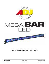
Alimentazione<br />
Mains<br />
L<br />
Alimentation<br />
Netz N<br />
Alimentación{<br />
MARRONE<br />
BLU<br />
GIALLO<br />
VERDE<br />
MARRON<br />
BLEU<br />
JAUNE<br />
VERT<br />
=<br />
=<br />
=<br />
=<br />
=<br />
=<br />
L<br />
N<br />
L<br />
N<br />
MARRÓN<br />
AZUL<br />
AMARILLO<br />
VERDE<br />
=<br />
=<br />
=<br />
L<br />
N<br />
BROWN<br />
BLUE<br />
YELLOW<br />
GREEN<br />
=<br />
=<br />
=<br />
L<br />
N<br />
BRAUN<br />
BLAU<br />
GELB<br />
GRÜN<br />
=<br />
=<br />
=<br />
L<br />
N<br />
6<br />
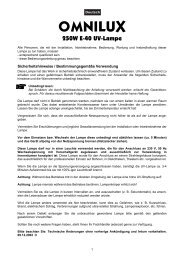
DMX 512<br />
5 PIN<br />
5 1<br />
4 2<br />
3<br />
SCREEN<br />
SIGNAL<br />
SIGNAL<br />
DMX 512<br />
DMX 512<br />
3 PIN<br />
SIGNAL<br />
SIGNAL<br />
3 1<br />
2<br />
SCREEN<br />
I<br />
GB<br />
F<br />
D<br />
E<br />
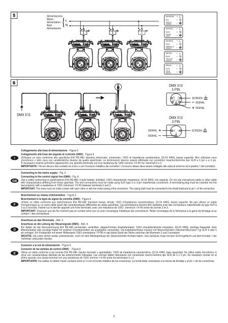
Collegamento alla linea di alimentazione - Figura 5<br />
Collegamento alla linea del segnale di controllo (DMX) - Figura 6<br />
Utilizzare un cavo conforme alle specifiche EIA RS-485: bipolare intrecciato, schermato, 120Ω di impedenza caratteristica, 22-24 AWG, bassa capacità. Non utilizzare cavo<br />
microfonico o altro cavo con caratteristiche diverse da quelle specificate. Le terminazioni devono essere effettuate con connettori maschio/femmina tipo XLR a 5 pin o a 3 pin.<br />
È necessario inserire sull’ultimo apparecchio uno spinotto terminale con una resistenza da 120Ω (minimo 1/4 W) tra i terminali 2 e 3.<br />
IMPORTANTE: I fili non devono fare contatto tra di loro o con l’involucro metallico dei connettori. L’involucro stesso deve essere collegato alla calza di schermo ed al piedino 1 dei connettori.<br />
Connecting to the mains supply - Fig. 5<br />
Connecting to the control signal line (DMX) - Fig. 6<br />
Use a cable conforming to specifications EIA RS-485: 2-pole twisted, shielded, 120Ω characteristic impedance, 22-24 AWG, low capacity. Do not use microphone cable or other cable<br />
with characteristics differing from those specified. The end connections must be made using XLR type 3 or 5-pin male/female connectors. A terminating plug must be inserted into the<br />
last projector with a resistance of 120Ω (minimum 1/4 W) between terminals 2 and 3.<br />
IMPORTANT: The wires must not make contact with each other or with the metal casing of the connectors. The casing itself must be connected to the shield braid and to pin 1 of the connectors.<br />
Branchement au réseau d'alimentation - Figure 5<br />
Branchement à la ligne du signal de contrôle (DMX) - Figure 6<br />
Utiliser un câble conforme aux spécifications EIA RS-485: bipolaire tressé, blindé, 120Ω d’impédance caractéristique, 22-24 AWG, basse capacité. Ne pas utiliser un câble<br />
microphonique ou un autre câble ayant des caractéristiques différentes de celles spécifiées. Les terminaisons doivent être réalisées avec des connecteurs mâle/femelle du type XLR à<br />
3 ou 5 broches. Insérer sur le dernier appareil une fiche terminale, avec une résistance de 120Ω (minimum 1/4 W) entre les bornes 2 et 3.<br />
IMPORTANT: S'assurer que les fils n'entrent pas en contact entre eux ou avec l'enveloppe métallique des connecteurs. Relier l'enveloppe de la fiche/prise à la gaine de blindage et au<br />
contact 1 des connecteurs.<br />
Anschluss an das Stromnetz - Abb. 5<br />
Anschluss an die Leitung der Steuersignale (DMX) - Abb. 6<br />
Ein Kabel mit der Kennzeichnung EIA RS-485 verwenden: verdrilltes, abgeschirmtes Zweileiterkabel, 120Ω charakteristische Impedanz, 22-24 AWG, niedrige Kapazität. Kein<br />
Mikrofonkabel oder sonstige Kabel mit anderen Charakteristiken als angegeben verwenden. Die Kabelabschlüsse müssen mit Steckverbindern (Steckern/Buchsen) Typ XLR 3 oder 5<br />
pin erfolgen. Ein Endstecker mit einem Widerstand 120Ω (mindestens 1/4 W) in das letzte Gerät der Reihe zwischen die Klemmen 2 und 3 einsetzen.<br />
WICHTIG: Die Leiter dürfen weder untereinander, noch mit dem Metallgehäuse der Steckverbinder Kontakt haben. Das Gehäuse muss mit dem Schirmgeflecht und dem Kontakt 1 der<br />
Verbinder verbunden werden.<br />
Conexión a la red de alimentación - Figura 5<br />
Conexión de las señales de control (DMX) - Figura 6<br />
Utilice un cable conforme a las normas EIA RS-485: bipolar trenzado y apantallado, 120Ω de impedancia característica, 22-24 AWG, baja capacidad. No utilice cable microfónico ni<br />
otros con características distintas de las anteriormente indicadas. Las uniones deben efectuarse con conectores macho-hembra tipo XLR de 3 o 5 pin. Es necesario montar en el<br />
último aparato una clavija terminal con una resistencia de 120Ω (mínimo 1/4 W) entre los terminales 2 y 3.<br />
IMPORTANTE: los cables no deben hacer contacto entre sí ni con la funda metálica de los conectores. La funda debe conectarse a la trenza de blindaje y al pin 1 de los conectores.<br />
7