
Create successful ePaper yourself
Turn your PDF publications into a flip-book with our unique Google optimized e-Paper software.
ISTRUZIONI PER L’INSTALLAZIONE, L’USO E LA MANUTENZIONEINSTALLATION, USE AND MAINTENANCE INSTRUCTIONSINSTRUCTIONS POUR L’INSTALLATION, L’EMPLOI ET L’ENTRETIENINSTALLATIONS-, BETRIEBS-UND WARTUNGSANLEITUNGENINSTRUCCIONES PARA LA INSTALACIÓN, EL USO Y EL MANTENIMIENTOTUTTAPIASTRA A GAS SERIE DOMINA 700SECONDO NORMA: EN 437 e EN 203 parte 1 e 2 Categoria II per Gas Metano e G.P.L.GAS SOLID TOP DOMINA 700 SERIESACCORDING TO: EN 437 and EN 203 part 1 and 2 Cat. II for Natural gas and L.P.G.PLAQUE COUPE-FEU GAZ SERIE DOMINA 700CONFORME AUX NORMES: EN 437 et EN 203 1ère et 2ème partie pour Gaz Méthane et G.P.L.GAS-GLÜHPLATTENHERDE SERIE DOMINA 700NACH: EN 437 und EN 203 Teil 1 und 2 Kategorie II für Erdgas und FlüssiggasPLANCHA A GAS SERIE DOMINA 700SEGÚN: EN 437 y EN 203 parte 1 y 2. Categoría II: Metano y G.P.L.GT...77GTF...77GTA...77I<strong>GB</strong>23/04/2007 Rev.2 1690550 6 9 4FDE
ITALIANO ................................................................................................ pagina 2 - 13ENGLISH ................................................................................................. page 14 - 26FRANÇAIS ............................................................................................... page 27 - 38DEUTSCH ................................................................................................ Seite 39 - 50ESPAÑOL ................................................................................................ página 51 - 62INDICECAPITOLO DESCRIZIONE PAGINAAvvertenze generali ............................................................................................................................. 31. Dati tecnici .......................................................................................................................................... 41.1 Tabella I: Tuttapiastra a gas serie (Domina 700) Categoria II (Gas Metano e G.P.L.) ....................... 41.2 Caratteristiche tecniche ....................................................................................................................... 41.3 Forno ................................................................................................................................................... 51.4 Riscaldamento a gas ......................................................................................................................... 51.5 Tuttapiastra .......................................................................................................................................... 52. Istruzioni per l’installazione ............................................................................................................... 52.1 Informazioni riguardanti i tuttapiastra a gas serie Domina 700 ......................................................... 52.2 Legge, norme e direttive tecniche da rispettare .................................................................................. 62.3 Luogo d’installazione ......................................................................................................................... 62.4 Posizionamento ................................................................................................................................... 62.5 Montaggio apparecchiatura top su base o supporto a sbalzo ............................................................. 62.6 Tabella II: Dati tecnici gas, pressione, ugelli bruciatore tuttapiastra, pilota e vite del minimo(Valido per tutti i tuttapiastra serie Domina 700) .............................................................................. 7Tabella II: Dati tecnici gas, pressione, ugelli bruciatore forno, pilota e vite del minimo(Valido per tutti i tuttapiastra serie Domina 700) .............................................................................. 7Tabella II: dati tecnici gas, pressione, ugelli bruciatore piccolo, pilota e vite del minimo (valido pertutti i tuttapiastra serie domina 700) ................................................................................................... 7Tabella II: dati tecnici gas, pressione, ugelli bruciatore medio, pilota e vite del minimo (valido pertutti i tuttapiastra serie domina 700) ................................................................................................... 73. Collegamento all’impianto del gas .................................................................................................... 83.1 Scarico dei prodotti di combustione .................................................................................................. 83.2 Apparecchi a gas tipo: A ..................................................................................................................... 83.3 Come ottenere la portata termica nominale ........................................................................................ 84. Controllo della pressione .................................................................................................................... 94.1 Controllo della pressione a monte (Pe) .............................................................................................. 94.2 Controllo della pressione all’ugello (Pi) ............................................................................................ 94.3 Regolazione della portata termica minima ......................................................................................... 94.4 come ottenere la portata termica nominale ......................................................................................... 94.5 Controllo per il funzionamento a gas liquido ............................................................................................. 94.6 Controllo del funzionamento .............................................................................................................. 94.7 introduzione dell’utente ..................................................................................................................... 95. Trasformazione per funzionamento ad altro tipo di gas ..................................................................... 105.1 forno .................................................................................................................................................... 105.1.1 sostituzione ugello bruciatore forno ................................................................................................... 105.1.2 sostituzione ugello bruciatore pilota .................................................................................................. 105.1.3 regolazione bruciatore forno ............................................................................................................... 105.2 tuttapiastra ........................................................................................................................................... 105.2.1 sostituzione ugello bruciatore ............................................................................................................ 105.2.2 sostituzione ugello bruciatore pilota .................................................................................................. 105.2.3 sostituzione della vite del minimo «by-pass» .................................................................................... 106. Istruzioni per l’utente .......................................................................................................................... 116.1 Accensione bruciatori forno ................................................................................................................ 116.2 Accensione bruciatori tuttapiastra ...................................................................................................... 117. Sostituzione dei componenti piu’ importanti ..................................................................................... 127.1 Sostituzione dei componenti .............................................................................................................. 128. Manutenzione e pulizia ...................................................................................................................... 13SCHEMI DI INSTALLAZIONE ........................................................................................................... 63I- 2 -
AVVERTENZE GENERALI- Leggere attentamente le avvertenze contenute nel presente libretto in quanto forniscono importanti indicazioniriguardanti la sicurezza di installazione, d’uso e di manutenzione.- Conservare con cura questo libretto per ogni ulteriore consultazione dei vari operatori.- Dopo aver tolto l’imballaggio, assicurarsi dell’integrità dell’apparecchiatura e in caso di dubbio, non utilizzarel’apparecchiatura e rivolgersi a personale professionalmente qualificato.- Prima di collegare l’apparecchiatura, accertarsi che i dati riportati sulla targhetta siano corrispondenti a quelli dellarete di distribuzione gas ed elettrica.- Questa apparecchiatura deve essere destinata solo all’uso per il quale è stata espressamente concepita, ognialtro uso è da considerarsi improprio e quindi pericoloso.- L’apparecchiatura deve essere utilizzata solo da persona addestrata all’uso della stessa.- Per eventuale riparazione rivolgersi solamente ad un centro di assistenza tecnica autorizzato dal costruttore erichiedere l’utilizzo di ricambi originali.- Il mancato rispetto di quanto sopra, può compromettere la sicurezza dell’apparecchiatura.- Non lavare l’apparecchiatura con getti d’acqua diretti e ad alta pressione.- Non ostruire le aperture o feritoie di aspirazione o di smaltimento del calore.IL TIPO DI UGELLO INDICATO NELLE TABELLE È FRUTTO DI SEVERE PROVE DI LABORATORIO PER CUI UNASOSTITUZIONE CON ALTRO DIFFERENTE, OLTRE CHE FAR CADERE OGNI GARANZIA NON PORTA NESSUN MI-GLIORAMENTO NELLE PRESTAZIONI O NEL MONTAGGIO.In caso di inosservanza delle norme contenute nel presente manuale, sia da parte dell’utente che da parte del tecnicoaddetto all’installazione, la Ditta declina ogni responsabilità ed ogni eventuale incidente o anomalia causato dallesuddette inosservanze non potrà essere imputato alla stessa.LA CASA COSTRUTTRICE DECLINA OGNI RESPONSABILITÀ PER LE POSSIBILI INESATTEZZE CONTENUTE NEL PRE-SENTE OPUSCOLO, IMPUTABILI AD ERRORI DI TRASCRIZIONE O STAMPA. SI RISERVA INOLTRE IL DIRITTO DI APPOR-TARE AL PRODOTTO QUELLE MODIFICHE CHE SI RITENGONO UTILI O NECESSARIE, SENZA PREGIUDICARE LE CARAT-TERISTICHE ESSENZIALI.- 3 - I
1. DATI TECNICI1.1 TABELLA I: TUTTAPIASTRA A GAS SERIE DOMINA 700 CATEGORIA II (GAS METANO E G.P.L.)MODELLOGT77GT2SD77GT2SDA77GT2SS77GT2SSA77GTA77GT4S77GT4SA77GTF77 GT2SDFA77 GT2SSFA77 GT4SF277 GT4SF2E77Dimensioni esterneLarghezzaProfonditàAltezzaAltezza tot. Tipo: ATipommmmmmmmA700735250425A1100735250425A700735250425A1500735250425A700735850925A1100735850925A1100735850925A1500735850925A1500735850925Attacco gasDimensioni armadioLarghezzaProfonditàAltezzaDimensione piastraLarghezzaProfonditàDimensioni forno GN2/1LarghezzaProfonditàAltezzaN° bruciatore e portatatermica nominalePiccolo (1)Medio (1)Piastra (1)Forno (1)Portata termica nom. totaleConsumo gasG.P.L G30/G31Metano H-G20Metano L-G25Assorbimento*Peso nettommmmmmmmmmN°mmmmmm3,5 kW6,0 kW9,0 kW6,0 kWkW(15°C)g/hm 3 /hm 3 /hkWkgG1/2”---670585---N°--1-9,0709-6990,9531,108-68G1/2”---670585---N°111-18,51457-14371,9582,277-85G1/2”---670585---N°111-18,51457-14371,9582,277-85G1/2”---670585---N°221-28,02205-21752,9643,447-110G1/2”---6705851560630295N°--11151183-11651,5871,846-120G1/2”3406503556705851560630295N°111124,51932-19032,5933,016-150G1/2”3406503556705851560630295N°111124,51932-19032,5933,016-150G1/2”---6705852560630295N°2212403,155-31084,2334,924-320G1/2”---6705852560630295N°2212 da 5,3kw*28,02205-21752,9643,447* 8,8320(1) Compreso la portata termica del pilota ca. 200W* Tensione: 1N AC220...240V 50/60 Hz.1.2 CARATTERISTICHE TECNICHESTRUTTURAStruttura portante in acciaio inox AISI 304, pannellatura e basamento in acciaio inox, montata su piedini regolabili in altezza.TERMOSTATI E RUBINETTI in ottone stampato, dotati di valvola di sicurezza con termocoppia per l’interruzione automaticadel gas in caso di spegnimento accidentale del pilota. Regolazione tra portata minima e massima.MANOPOLE RUBINETTI in materiale atermico.I- 4 -
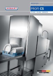
1.3 FORNOCAMERA DI COTTURA in acciaio inox smaltato resistente alle alte temperature e agli acidi, di dimensioni interne conformialle GASTRONORM 2/1. Isolamento termico con lana di vetro ad alta densità. Supporti laterali griglia in tondino di acciaiocromato, facilmente estraibili per le pulizie. Griglia in tondino d’acciaio cromato.PORTE FORNO a doppia parete con intercapedine isolante in lana di vetro, controporte in acciaio inox, maniglie in acciaiosatinato e guarnizione di tenuta alla porta. Cerniere a molla bilanciate.1.4 RISCALDAMENTO A GASCon bruciatore in acciaio inox a fiamma autostabilizzata. Regolazione termostatica della temperatura 150 ÷ 290 °C convalvola di sicurezza con termocoppia per l’interruzione automatica del gas in caso di spegnimento accidentale del pilota.Accensione piezoelettrica al pilota «Targhet» del forno.1.5 TUTTAPIASTRAPIASTRA di cottura in ghisa con disco “zona di cottura rapida” centrale estraibile.BRUCIATORE in acciaio inox AISI 304 con fiamma stabilizzata; accensione con fiamma pilota «Targhet», con ugelli fissiper i diversi tipi di gas.ACCENSIONE piezoelettrica del bruciatore pilota.RUBINETTO in ottone stampato, dotato di valvola di sicurezza con termocoppia per l’interruzione automatica del gas incaso di spegnimento accidentale del pilota. Regolazione tra portata minima e massima.CAMERA DI COMBUSTIONE in acciaio inox AISI 430 isolato con fibre di ceramica (Ossidi di Alluminio e Silicio).2. ISTRUZIONI PER L’INSTALLAZIONEL’installazione e l’eventuale trasformazione per l’uso di altri tipi di gas, deve essere eseguita da persone qualificatesecondo la normativa in vigore.Vedere tabelle dati tecnici: 1.1 e 2.6AVVERTENZE:Nel caso in cui l’apparecchiatura venga installata contro una parete quest’ultima deve resistere ai valori di temperatura di90°C e deve essere incombustibile.Prima di procedere all’installazione, togliere dal rivestimento la pellicola di protezione in plastica, eliminando gli eventualiresidui adesivi con prodotto adatto alla pulizia per l’acciaio inossidabile.Installare l’apparecchio in posizione orizzontale, la corretta posizione si otterrà ruotando i piedini livellatori.Qualora l’apparecchiatura venga installata singolarmente si consiglia di fissarla per rendere più sicura la sua stabilità.2.1 INFORMAZIONI RIGUARDANTI I TUTTAPIASTRA A GAS SERIE DOMINA 700Questo libretto è valido per nostri Tuttapiastra serie DOMINA 700 del tipo A Categoria II (Gas naturale e Liquido G.P.L.).Vedere tabella 1.1 e 2.6La targhetta secondo le norme EN437 e EN203 parte 1 si trova:a) sugli apparecchi con forno, sul pannelloanteriore-inferioreb) sugli apparecchi senza forno, nell’armadioin basso a sinistra.c) sugli apparecchi top, sul retro o all’internoEsempio targhetta Italia: Cat. II 2H3+Pe = Pressione a montePi = Pressione all’ugelloMod.Matr.N°V Hz kWCat.P nCat.P nQn(Hi)IT-GR-<strong>GB</strong>-ES-IE-PTII2H3+PTII2H3+20,50/6720,29/37NO-SE-EE-LT-DK-LV-CZ-SK-SI-FI-TR-HR-BG-ROII2H3B/P20,30/30KWG20G25m 3 /hm 3 /hNLII2L3B/P25,30,30G30G31TypetipoIS-MT-CY PL FR - BE DE LUI3B/P30/30II2E3P20/37II2E+3+20/25,29/37II2ELL3B/P20,20,50/50I2E; I3+20,29/37AT-CHII2H3B/P20,50/50mbarmbarKg/hKg/h- 5 - I
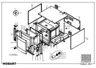
2.2 LEGGE, NORME E DIRETTIVE TECNICHE DA RISPETTAREPer l’installazione sono da osservare le seguenti norme:- Prescrizioni vigenti antinfortunistiche e antincendio.- La regolamentazione dell’ente erogatore del gas, dal quale bisogna farsi rilasciare il nullaosta prima dell’installazione.- Norme «Installazione impianti a gas».- Norme «Installazione impianti elettrici».- La regolamentazione dell’ente erogatore energia elettrica.- Norme igieniche.2.3 LUOGO D’INSTALLAZIONE- L’apparecchio deve essere installato in locali consufficiente areazione. Questo apparecchio richiede unaaspirazione di almeno 2 m 3 /h • kW P.T. (Portata Termica).- Installare l’apparecchiatura secondo quanto previsto dalle norme di sicurezza UNI - CIG 8723, legge N° 46 del 5-3-’90 eD.M. N°74 del 12.04.96.2.4 POSIZIONAMENTO- Le varie apparecchiature possono essere installate singolarmente o possono essere accoppiate ad altre apparecchiaturedella nostra stessa gamma.- Questa apparecchiatura non è idonea per l’incasso.- La distanza dalla pareti laterali deve essere minimo di 10 cm., nel caso in cui la distanza fosse inferiore o il materiale dellepareti o del pavimento fossero infiammabili, è indispensabile l’applicazione di un isolante termico.2.5 MONTAGGIO APPARECCHIATURA TOPSU BASE O SUPPORTO A SBALZOTutte le apparecchiature top sono munite di piediniregolabili in altezza (P):- Quando l’apparecchiatura deve essere sistemata liberasu un tavolo o un piano, avvitare o svitare i piedini (P)come indicato in figura sino a farla appoggiareperfettamente, quindi stringere il controdado (D) inmodo da bloccare il piedino. Per impedirle di scivolare,infilare nei buchi inferiori dei piedini i tappi in gomma(M).- Quando l’apparecchiatura deve essere fissata su unabase o su un supporto a sbalzo, regolare i piedini (P)sino a farla appoggiare perfettamente, stringere poi ilcontrodado (D) in modo da bloccare il piedino. Fissarequindi da sotto mediante viti M5 (T) con relativerondelle avvitandole ai piedini come indicato in figura.I- 6 -
2.6 TABELLA II: DATI TECNICI GAS, PRESSIONE, UGELLI BRUCIATORE TUTTAPIASTRA, PILOTA E VITEDEL MINIMO (VALIDO PER TUTTI I TUTTAPIASTRA SERIE DOMINA 700)NazioneeCategoriaCat.UGELLOTipodiGASPRESSIONE GASA MONTE mbarBRUCIATORETUTTAPIASTRABY-PASSPEL COPRECIPILOTAPress. Gasall’Ugellocon 21SPortataTermicanom. kW (1)ConsumoGas(15°C)Nom. Min. MaxØ mmTipoMARCATOR.d.AX mmØ mmMARCATO“targhet”MARCATOMaxmbarMin.mbar100% P.T.Min.l/hg/hITALIA II2H3+2HG20metano201725215 KF1801803618,83,49,03,7953-ITALIA II2H3+3+G30butanoG31propano293720253545150 KF1001001928,636,44,35,69,03,7279368710699TABELLA II: DATI TECNICI GAS, PRESSIONE, UGELLI BRUCIATORE PICCOLO, PILOTA E VITE DEL MINIMO(VALIDO PER TUTTI I TUTTAPIASTRA SERIE DOMINA 700)NazioneeCategoriaCat.UGELLOTipodiGASPRESSIONE GASA MONTE mbarBRUCIATOREFORNOBY-PASSPEL SABAFPILOTAPress. Gasall’Ugellocon 25STPortataTermicanom. kW (1)ConsumoGas(15°C)Nom. Min. MaxØ mmTipoMARCATOR.d.AX mmØ mmMARCATO“targhet”MARCATOMaxmbarMin.mbar100% P.T.Min.24%l/hg/hITALIA II2H3+2HG20metano201725185 K1595 953618,41,36,01,55634-ITALIA II2H3+3+G30butanoG31propano293720253545125 K1565 651928,736,91,82,56,01,55186245473466TABELLA II: DATI TECNICI GAS, PRESSIONE, UGELLI BRUCIATORE FORNO, PILOTA E VITE DEL MINIMO(VALIDO PER TUTTI I TUTTAPIASTRA DOMINA 700)NazioneeCategoriaCat.UGELLOTipodiGASPRESSIONE GASA MONTE mbarBRUCIATOREPICCOLOBY-PASSPEL COPRECIPILOTAPress. Gasall’Ugellocon 21SPortataTermicanom. kW (1)ConsumoGas(15°C)Nom. Min. MaxØ mmTipoMARCATOR.d.AX mmØ mmMARCATO“targhet”MARCATOMaxmbarMin.mbar100% P.T.Min.33%l/hg/hITALIA II2H3+2HG20metano201725140 KF85903519,82,203,51,35370-ITALIA II2H3+3+G30butanoG31propano29372025354595 KF55552128,936,93,304,303,51,35108142276272TABELLA II: DATI TECNICI GAS, PRESSIONE, UGELLI BRUCIATORE MEDIO, PILOTA E VITE DEL MINIMO(VALIDO PER TUTTI I TUTTAPIASTRA SERIE DOMINA 700)NazioneeCategoriaCat.UGELLOTipodiGASPRESSIONE GASA MONTE mbarBRUCIATOREMEDIOBY-PASSPEL COPRECIPILOTAPress. Gasall’Ugellocon 21SPortataTermicanom. kW (1)ConsumoGas(15°C)Nom. Min. MaxØ mmTipoMARCATOR.d.AX mmØ mmMARCATO“targhet”MARCATOMaxmbarMin.mbar100% P.T.Min.35%l/hg/hITALIA II2H3+2HG20metano201725175 KF110 1153519,72,46,02,15635-ITALIA II2H3+3+G30butanoG31propano293720253545115 KF75 752128,936,94,45,76,02,15186243473466R.dA. = Regolazione dell’aria primaria F = Fisso R = Regolabile K = Ugello corto L =15 mm(1) Compresa portata termica pilota circa 200 W.Marcatura ugello Ø 1/100 mm.- 7 - I
3. COLLEGAMENTO ALL’IMPIANTO DEL GAS- L’apparecchio deve essere alimentato con gas avente le caratteristiche e la pressione riportata in tabella II.- La pressione del gas si misura alla presa di pressione iniziale con i bruciatori accesi (vedere Fig. 1 e art. 3.2).- L’apparecchiatura è collaudata e predisposta per funzionare a gas metano H-G20 - 20 mbar.* N.B. Se la pressione in rete varia più del +10% della pressione nominale, viene consigliato di montare un regolatoredi pressione a monte dell’apparecchio per garantire la pressione nominale.- L’allacciamento alla rete del gas deve essere effettuato con tubazione metallica di adeguata sezione e deve essere inseritoa monte un rubinetto di intercettazione omologato.- Dopo l’allacciamento alla rete del gas, controllare che non esistano perdite nei punti di raccordo con appositi strumentio acqua saponata.3.1 SCARICO DEI PRODOTTI DI COMBUSTIONEGli apparecchi devono essere installati in locali adatti per lo scarico dei prodotti della combustione che deve avvenire nelrispetto di quanto prescritto dalle norme d’installazione. Le nostre apparecchiature sono considerate (vedi Tabella 1.1 datitecnici)3.2 APPARECCHI A GAS TIPO: ANon sono previsti per essere collegati ad un controllo di scarico dei prodotti della combustione.L’apparecchiatura a gas va sistemata sotto una cappa di aspirazione il cui impianto deve avere le caratteristiche conformi alleNorme. Questa apparecchiatura necessita di almeno 2 m 3 /h • kW P.T. (P.T. = Portata Termica).Controllare l’aerazione della cucina; deve essere secondo le norme in vigore.3.3 COME OTTENERE LA PORTATA TERMICA NOMINALEControllare se l’apparecchio è predisposto per il tipo di gas, pressione e categoria che corrisponde con il gas disponibile inrete.Indicazione riportata sull’imballo e/o targhetta sull’apparecchio.Se l’apparecchio è predisposto per un altro tipo di gas e pressione, occorre prima fare una trasformazione per il funzionamentoad altro tipo di gas.Vedere la Tabella II per l’ugello, vite del minimo (by-pass), regolazione dell’aria primaria, (X mm), l’ugello del pilota e lapressione all’ugello del bruciatore principale.N.B.: I nomi degli ugelli «2H» e «3+» sono visibili nella parte sinistra della Tabella II.2H = G 20 - 20 mbar3 + = G 30 - 29 mbar e/o G 31 - 37 mbar una coppia di gas e pressione. Nel nostro settore abbiamo quasi sempre a che fare conG 31 - 37 mbar!Nella Tabella II sono riportati i tipi di gas e pressione per tutti i bruciatori e i relativi ugelli, la distanza X mm della regolazionedell’aria primaria (vedere Fig. 4), la vite del minimo (by-pass), l’ugello del pilota, la pressione massima e minima all’ugello,la portata termica massima e minima e il consumo gas in l/h (15°C) o in g/h in caso di G.P.L.Attenzione:Se la pressione «dinamica» del gas a monte dell’apparecchio è inferiore alla pressione minima della Tabella II,l’allacciamento è proibito; l’installatore deve comunicare all’azienda del gas che la pressione in rete è troppo bassa.N.B. Se la pressione varia più del +10% della pressione nominale p.e. per G 20 • 22 mbar viene consigliato di montare unregolatore di pressione a monte dell’apparecchio per garantire la pressione nominale.Se la pressione in rete è oltre la pressione massima della Tabella II p.e. per G 20 • 25 mbar avvertire l’azienda del gas.Controllare se la pressione in entrata ed all’ugello corrisponde con i valori riportati nella Tabella II.I- 8 -
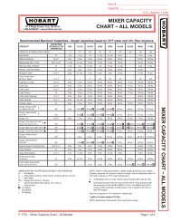
4. CONTROLLO DELLA PRESSIONE4.1 CONTROLLO DELLA PRESSIONE A MONTE (PE) FIG. 1La pressione viene misurata con un manometro 0 ÷ 80 mbar (Precisione almeno 0,1 mbar).La presa di pressione Fig. 1 si trova sulla rampa gas G 1/2" dietro il cruscottto; svitare la vite (A) della presa di pressione (B),attaccare la gomma al silicone nel manometro, accendere i bruciatori e rilevare la pressione «dinamica» a monte.Rimontare la vite (A) con rondella di tenuta gas (C) e controllare la tenuta gas con bolle di sapone.4.2 CONTROLLO DELLA PRESSIONE ALL’UGELLO (PI) FIG. 2.La presa di pressione si trova sopra il porta ugello (fig. 2).La gomma al silicone è adattta per alte temperature e va protetta con carta stagnola per evitare che questa bruci, specialmentenel forno o piastra di cottura.4.3 REGOLAZIONE DELLA PORTATA TERMICA MINIMALa portata termica minima, viene ottenuta con la vite del minimo by-pass «calibrata» avvitata a fondo secondo la Tabella II.4.4 COME OTTENERE LA PORTATA TERMICA NOMINALEControllare se l’apparecchio è predisposto per il tipo di gas, pressione e categoria che corrisponde con il gas disponibile inrete.Indicazione riportata sull’imballo e/o targhetta sull’apparecchio.Se l’apparecchio è predisposto per un altro tipo di gas e pressione, occorre prima fare una trasformazione per il funzionamentoad altro tipo di gas. Vedere la Tabella II per l’ugello, vite del minimo (by-pass), regolazione dell’aria primaria, (X mm), l’ugellodel pilota e la pressione all’ugello del bruciatore principale.N.B. I nomi degli ugelli «2H» e «3+» sono visibili nella parte sinistra della Tabella II.2H = G 20 - 20 mbar3 + = G 30 - 29 mbar e/o G 31 - 37 mbar una coppia di gas e pressione. Nel nostro settore abbiamo quasi sempre a che fare conG 31 - 37 mbar!Nella Tabella II sono riportati i tipi di gas e pressione per tutti i bruciatori e i relativi ugelli, la distanza X mm della regolazionedell’aria primaria (vedere Fig. 3), la vite del minimo (by-pass), l’ugello del pilota, la pressione massima e minima all’ugello,la portata termica massima e minima e il consumo gas in l/h (15°C) o in g/h in caso di G.P.L.Attenzione: Se la pressione «dinamica» del gas a monte dell’apparecchio è inferiore alla pressione minima della Tabella II,l’allacciamento è proibito; in più l’installatore deve comunicare all’azienda del gas che la pressione in rete è troppo bassa.N.B. Se la pressione varia più del +10% della pressione nominale p.e. per G 20 • 22 mbar viene consigliato di montare unregolatore di pressione a monte dell’apparecchio per garantire la pressione nominale.Se la pressione in rete è oltre la pressione massima della Tabella II p.e. per G 20 • 25 mbar avvertire l’azienda del gas.Controllare se la pressione in entrata ed all’ugello corrisponde con i valori riportati nella Tabella II.4.5 CONTROLLO PER IL FUNZIONAMENTO A GAS LIQUIDOControllare se gli ugelli montati corrispondono con l’indicazione delle Tabelle II Cap. 2.6.Verificare se la pressione in entrata corrisponde con le indicazioni della Tabella II.Controllare se l’impianto a gas G.P.L. ha due regolatori di pressione di sufficiente capacità e se la capacità di evaporazionepuò essere considerata sufficiente.Vedere anche la pubblicazione «Norme di installazione e caratteristiche di Impianti a gas G.P.L.».4.6 CONTROLLO DEL FUNZIONAMENTO- Mettere l’apparecchio in funzione secondo le istruzioni d’uso.- Controllare che non ci siano delle perdite di gas secondo le normative locali.- Controllare l’accensione e l’interaccensione del bruciatore pilota e bruciatore principale.- Verificare lo scarico regolare dei gas della combustione.- Scrivere su una targhettina adesiva da incollare sulla targhetta della apparecchiatura per quale gas e pressione l’apparecchioè stato regolato.4.7 INTRODUZIONE DELL’UTENTESpiegare il funzionamento e l’uso all’utente utilizzando il libretto istruzioni e illustrare eventuali cambiamenti.Lasciare il libretto istruzioni in mano all’utente e spiegare che lo deve utilizzare per ulteriori consultazioni.- 9 - I
5. TRASFORMAZIONE PER FUNZIONAMENTO AD ALTRO TIPO DI GAS5.1 FORNO5.1.1 SOSTITUZIONE UGELLO BRUCIATORE FORNODopo aver tolto il piano del forno; smontare la scatola di protezione.- Sostituire l’ugello del bruciatore con una chiave del 12 (Fig. 4 pos. 4) con quello corrispondente al tipo di gas presceltoattenendosi alla Tabella II Iniettori Cap. 2.65.1.2 SOSTITUZIONE UGELLO BRUCIATORE PILOTAN.B.: Si consiglia di smontare subito la candeletta per evitare di romperla.Svitare il dado con una chiave 10 mm. (Fig. 4 pos. 2) e smontare l’ugello (Fig. 4 pos. 1). L’ugello è agganciato al bicono(Fig. 4 pos. 3).Sostituire l’ugello pilota (Fig. 4 pos. 1) con quello corrispondente al gas prescelto secondo quanto riportato nella Tabella IIIniettori Cap. 2.6Stringere bene il dado con una chiave da 10 mm., e controllare la tenuta gas con bolle di sapone.5.1.3 REGOLAZIONE BRUCIATORE FORNOSostituire la vite del minimo (Fig. 5 pos. 11) situata sul termostato con quella corrispondente al tipo di gas prescelto TabellaII Iniettori Cap. 2.6L’aria primaria viene regolata impostando il regolatore dell’aria primaria (Fig. 4 pos. 8) secondo quanto riportato sulla TabellaII Iniettori Cap. 2.6Dopo aver regolato la distanza, bloccare con la vite; rimontare la protezione dopo aver montato la vite della presa dipressione.5.2 TUTTAPIASTRA5.2.1 SOSTITUZIONE UGELLO BRUCIATORETogliere le manopole dei rubinetti.Dopo aver tolto il cruscotto (svitare le 4 viti), si può facilmente cambiare l’ugello (Fig. 6 pos. 9) con quello per il tipo di gasprescelto usando una chiave del 12, attenendosi alla Tabella II Iniettori Cap. 2.6.Il bruciatore non ha la possibilità di regolare la quantità dell’aria primaria.5.2.2 SOSTITUZIONE UGELLO BRUCIATORE PILOTAN.B. Per evitare di rompere la candeletta d’accensione (Fig. 6 pos. 4) conviene toglierla usando una chiave del 10.Il burciatore pilota è del tipo “Targhet” cioè senza regolazione dell’aria primaria e ha gli ugelli fissi.Svitare il dado con chiave da 10 mm. (Fig. 6 pos. 4) e smontare l’ugello pilota (Fig. 6 pos. 5) che è agganciato al bicono(Fig. 6 pos. 3). Sostituire l’ugello pilota con quello corrispondente al gas prescelto secondo quanto riportato nella TabellaII Iniettori Cap. 3.4.0. Stringere molto bene il dado con chiave 10 mm.5.2.3 SOSTITUZIONE DELLA VITE DEL MINIMO «BY-PASS»Sul rubinetto si trova la vite della portata termica minima o “By-pass” (Fig. 2 pos. 1).Svitare con un cacciavite la vite del minimo e sostituirla con quella corrispondente al gas prescelto secondo quanto riportatonella Tabella II Iniettori Cap. 2.6. La vite del minimo va avvitata a fondo contro la sua sede.Accendere il bruciatore pilota, e portare la manopola in posizione di minimo e procedere alla eventuale regolazione dellaportata del minimo (Fig. 2 pos. 1) secondo quanto riportato nella Tabella II Iniettori Cap. 2.6Verificarelapressioneminimaall’ugello. La portata termica in posizione di minimo deve essere circa 50% della portata termicanominale. Il bruciatore della piastra di cottura non deve spegnersi quando si gira la manopola velocemente dalla posizionemassima ( ) alla posizione minima ( ). La vite del minimo va stretta bene fino in fondo quando questa ha un foro calibrato(vedere tabella).Terminata la sostituzione degli ugelli, applicare sopra alla targhetta esistente quella data in dotazione alla macchinaindicante il nuovo tipo di gas.I- 10 -
6. ISTRUZIONI PER L’UTENTE6.1 ACCENSIONE BRUCIATORI FORNO- Per accendere il pilota del forno, premere la manopola (Fig. 8) ruotandola verso sinistra in corrispondenza del simbolo( ), raggiunta la posizione, premere a fondo la manopola schiacciando contemporaneamente il pulsante dell’accensionepiezoelettrica (Fig. 8).- Il pilota, visibile attraverso i fori posti sul piano del forno si accenderà, tenere premuto la manopola per circa 15 secondie quindi rilasciarla. Se il pilota dovesse spegnersi, ripetere l’operazione.- Per accendere e regolare il bruciatore, girare la manopola nella posizione desiderata.- Per spegnere il bruciatore, riportare la manopola in posizione ( ) per lo spegnimento totale, riportare la manopola inposizione ( ).6.2 ACCENSIONE BRUCIATORI TUTTAPIASTRAPer accendere il pilota del tuttapiastra, premere la manopola (Fig. 7), ruotandola verso sinistra fino al simbolo ( ) raggiuntala posizione premere a fondo e procedere all’accensione del pilota schiacciando contemporaneamente il pulsante dell’accensionepiezoelettrica; il pulsante si trova sul cruscotto. Il bruciatore pilota è visibile attraverso l’oblò sul cruscotto.Mantenere premuta la manopola per circa 15 secondi; al suo rilascio, la fiammella del pilota deve rimanere accesa. Se ciò nonavvenisse, ripetere l’operazione di accensione.Per accendere il bruciatore al massimo ruotare la manopola in posizione ( ) ed in posizione ( ) per il minimo. Per spegnereil bruciatore, girare la manopola in senso contrario portandola sul simbolo (manopola sullo zero ( ).) per spegnere anche il pilota ruotare laNOTA: Il tuttoapiastra non è adatto per la cottura diretta dei cibi, il disco centrale raggiunge una temperatura di circa500°C; non utilizzare olio per le cotture.- 11 - I
7. SOSTITUZIONE DEI COMPONENTI PIU’ IMPORTANTI7.1 SOSTITUZIONE DEI COMPONENTIDa effettuarsi solo da un “Centro Assistenza Autorizzato”!!.Per poter cambiare i seguenti componenti si deve per prima cosa:- chiudere il rubinetto gas in entrata;- togliere le manopole;- smontare il frontalino;- eventualmente togliere le griglie, gli spartifiamma e i bruciatori.Adesso si possono sostituire i componenti più importanti.A) Termostato forno (Fig. 5) “Solo per gli apparecchi con forno a gas”.Il termostato si trova sulla rampa di alimentazione.- smontare la termocoppia (16) con una chiave del 19;- smontare per primo l’uscita del gas verso i bruciatori (13 e 15);- smontare il bulbo che si trova all’interno del forno e viene fissato con squadrette porta bulbo;- smontare l’entrata del gas (12) con una chiave del 9;- montare il nuovo termostato seguendo l’ordine inverso di smontaggio;- cambiare la vite del minimo “By-pass” (11);- montare il bulbo nel forno usando le sue squadrette.N.B.: Controllare che non vi siano fughe di gas usando bolle di sapone, la tenuta deve essere perfetta.B) Termocoppia forno (Fig. 4 pos. 6 e Fig. 5 pos. 16)- togliere il fondo del forno;- smontare il dado sul termostato con una chiave del 9 (Fig. 5 pos. 16);- smontare il dado (Fig. 4 pos. 6) con una chiave del 10;- montare una termocoppia targhet nuova seguendo l’ordine inverso di smontaggio.N.B.: Termocoppia unificata SIT: da tenere 4 o 5 mm indietro rispetto al suo fermo.C) Candeletta bruciatore pilota forno (Fig. 4 pos. 5)- eliminare il fondo del forno;- staccare il cavo dell’alta tensione;- smontare la candeletta svitando il dado con una chiave del 10;- montare una nuova candeletta seguendo l’ordine inverso di smontaggio.D) Accenditore piezoelettrico forno e/o piastraE’ molto semplice smontare l’accenditore dal cruscotto del forno;- staccare il cavo dell’alta tensione;- svitare il dado con una chiave del 25;- montare l’accenditore nuovo seguendo l’ordine inverso di smontaggio.E) Rubinetto tuttapiastra (Fig. 2)- smontare la termocoppia (3) con una chiave del 9;- smontare l’alimentazione (4) del bruciatore pilota con una chiave del 10;- smontare l’uscita (5) e poi l’entrata del gas (6);- montare un nuovo rubinetto seguendo l’ordine inverso di smontaggio;- invertire la vite del minimo “By-pass” (1).N.B.: Controllare che non vi siano fughe di gas usando bolle di sapone, la tenuta deve essere perfetta.F) Candeletta bruciatore pilota del tuttopiastra (Fig. 6)- staccare il cavo dell’alta tensione;- svitare il dado (7) con una chiave del 10;- montare una nuova candeletta seguendo l’ordine inverso di smontaggio.G) Termocoppia del tuttapiastra (Fig. 6)- staccare il cavo dell’alta tensione;- smontare la candeletta (6) vedere (H);- smontare la termocoppia (Fig. 2 pos. 3) con una chiave del 9;- smontare la termocoppia (1) con una chiave del 10; dado (2);- montare la nuova termocoppia seguendo l’ordine inverso di smontaggio.I- 12 -
H) Bruciatore pilota del tuttapiastra (Fig. 6)- smontare per prima cosa la candeletta (veder H);- smontare poi la termocoppia (vedere I);- smontare il dado (4) dall’alimentazione gas con una chiave del 10;- l’ugello (5) rimane agganciato al bicono (3);- cambiare l’ugello (5) se questo non è in buono stato;- smontare il pilota dalla staffa con una chiave brugola di 4 mm.;- montare un nuovo bruciatore “Targhet”;- stringere molto bene il dado (4);- rimontare il tutto seguendo l’ordine inverso di smontaggio.N.B.: Controllare che non vi siano fughe di gas usando bolle di sapone, la tenuta deve essere perfetta.8. MANUNTENZIONE E PULIZIA- Pulire giornalmente la parti in acciaio inox con acqua tiepida saponata, quindi risciacquare abbondantemente ed asciugarecon cura.- Evitare nel modo più assoluto di pulire l’acciaio inox con paglietta, spazzola o raschietti di acciaio comune in quantopossono depositare particelle ferrose che ossidandosi provocano punti di ruggine. Può essere eventualmente adoperatalana di acciaio inossidabile passata nel senso della satinatura.- Qualora l’apparecchiatura non venga utilizzata per lunghi periodi, passare energicamente su tutte le superfici in acciaioun panno appena imbevuto di olio di vaselina, in modo da stendere un velo protettivo. Arieggiare periodicamente i locali.PIASTRA DI COTTURAPulire frequentemente la piastra usando uno strofinaccio umido, successivamente metterla in funzione per qualche minutoposizionando le manopole al massimo allo scopo di asciugarla nel più breve tempo possibile. Al termine lubrificarla con unleggero strato di olio di vaselina.PARTI IN ACCIAIO INOSSIDABILEAnche i particolari in acciaio inox debbono essere puliti con acqua saponata e poi asciugati con un panno morbido.La lucentezza viene mantenuta mediante ripassatura periodica, con (POLISH) liquido, un prodotto reperibile ovunquePARTI SMALTATEPer mantenere a lungo la lucentezza delle parti smaltate, è necessario pulirle frequentemente con acqua saponata tiepida.Non permettere che l’aceto, il caffè, il latte, l’acqua salina, il succo di limone e di pomodoro rimangano per lungo tempo acontatto con la superficie smaltata.- 13 - I
INDEXCHAPTER DESCRIPTION PAGEGeneral remarks ............................................................................................................................................... 151. Technical data.................................................................................................................................................. 161.1 Table I : Gas solid top DOMINA 700 series, Category II (Natural gas and L.P.G.) ........................................ 161.2 Technical characteristics .................................................................................................................................. 161.3 Oven ................................................................................................................................................................. 171.4 Gas heating ...................................................................................................................................................... 171.5 Gas solid top .................................................................................................................................................... 172. Installation instructions ................................................................................................................................... 172.1 Information about gas solid top DOMINA 700 series ..................................................................................... 172.2 Laws, regulations and technical directives to be complied with .................................................................... 182.3 Installation place ............................................................................................................................................. 182.4 Positioning ....................................................................................................................................................... 182.5 Mounting the top units on a base or an extending support ............................................................................ 182.6 Table II: Gas technical data, pressure, solid top burner nozzles, pilot and idle screw(Valid for all gas solid tops Domina 700 series) ............................................................................................. 19Table II: Gas technical data, pressure, oven burner nozzles, pilot and idle screw(Valid for all gas solid tops Domina 700 series) ............................................................................................. 19Table II: gas technical data, pressure, medium burner nozzles, pilot and idle screw (valid for all gas solidtops domina 700 series) ................................................................................................................................... 20Table II: gas technical data, pressure, small burner nozzles, pilot and idle screw (valid for all gas solid topsdomina 700 series) ........................................................................................................................................... 203. Gas system connection .................................................................................................................................... 213.1 Discharge of exhaust flue products ................................................................................................................. 213.2 Gas units type A ............................................................................................................................................... 213.3 How to achieve the nominal thermal capacity ............................................................................................... 214. Pressure check.................................................................................................................................................. 224.1 Incoming pressure check (Pe).......................................................................................................................... 224.2 Nozzle pressure check (Pi) .............................................................................................................................. 224.3 Adjusting the minimum thermal capacity ....................................................................................................... 224.4 how to achieve the nominal thermal capacity ................................................................................................. 224.5 Liquid gas operation control ........................................................................................................................... 224.6 Operation control ............................................................................................................................................. 224.7 Introduction to users ........................................................................................................................................ 225. Trasformation to operate with other gas type .................................................................................................. 235.1 Oven ................................................................................................................................................................. 235.1.1 Replacing the oven burner nozzle ................................................................................................................... 235.1.2 Replacing the pilot burner nozzle ................................................................................................................... 235.1.3 Adjusting the oven burner ............................................................................................................................... 235.2 Solid top........................................................................................................................................................... 235.2.1 Replacing the burner nozzle ............................................................................................................................ 235.2.2 Replacing the pilot burner nozzle ................................................................................................................... 235.2.3 Replacing the idle bypass screw ...................................................................................................................... 236. Instructions to user ........................................................................................................................................... 246.1 Igniting the oven burners ................................................................................................................................ 246.2 Igniting the solid top burners .......................................................................................................................... 247. Replacing important components ................................................................................................................... 247.1 Replacing components .................................................................................................................................... 248. Maintenance and cleaning .............................................................................................................................. 26INSTALLATION DIAGRAMS ......................................................................................................................... 63<strong>GB</strong>- 14 -
GENERAL REMARKS- Carefully read the instructions contained in the present booklet as they supply important informationrelating to safe installation, use and maintenance.- Keep this booklet with care, for any further consultation by the various operators.- Having removed the packing, make sure the unit is in good order and in case of doubt, do not use the unit, but callon skilled personnel.- Before connecting the unit, make sure the data appearing on the label correspond to those of the main gas supply.- This unit must only be destined to the use it was expressely built for; any other use must be deemed improper andtherefore dangerous.- The unit must be used only by a person trained for its operation.- For any repairs, please call exclusively a technical service centre authorised by the manufacturer, and ask fororiginal spare parts only.- The non-compliance of the above can compromise unit safety.- Do not wash the unit with direct or high-pressure water jets.- Do not obstruct openings or draft grids or heat vents.THE TYPE OF NOZZLE INDICATED IN THE TABLES IS THE RESULT OF STRICT LABORATORY EXPERIMENTS:REPLACING IT WITH A DIFFERENT ONE, APART FROM MAKING THE GUARANTEE VOID, DOES NOT IMPROVETHE PERFORMANCES OR THE ASSEMBLY.In case of non-compliance with the indications contained in the present manual, both on the user’s part and on theinstalling technician’s part, the Manufacturer declines any esponsibility, and any possible accident or fault caused by theabove mentioned non-compliances will not be imputable to the Manufacturer.The Manufacturer declines any responsibility for any imprecisions appearing on the present booklet, ascribable to transcriptionor printing errors. Furthermore, the Manufacturer reserves the right to make any modifications to the product deemed usefulor necessary, without prejudicing its essential characteristics.- 15 - <strong>GB</strong>
1. TECHNICAL DATA1.1 TABLE I : GAS SOLID TOP DOMINA 700 SERIES, CATEGORY II (NATURAL GAS AND L.P.G.)MODELGT77GT2SD77GT2SDA77GT2SS77GT2SSA77GTA77GT4S77GT4SA77GTF77 GT2SDFA77 GT2SSFA77 GT4SF277 GT4SF2E77External dimensionsWidthDepthHeightTotal Height Type ATipommmmmmmmA700735250425A1100735250425A700735250425A1500735250425A700735850925A1100735850925A1100735850925A1500735850925A1500735850925Gas connectionCabinet dimensionsWidthDepthHeightPlate diemensionsWidthDepthGN2/1 Oven dimensionsWidthDepthHeightBurner No. and nominalthermal capacitySmall (1)Medium (1)Plate (1)Oven (1)mmmmmmmmmmN°mmmmmm3,5 kW6,0 kW9,0 kW6,0 kWTotal nominal thermal cap. kWGas consumption (15°C)L.P.G. G30/G31g/hNatural Gas H-G20 m 3 /hNatural Gas L-G25 m 3 /hAbsorption*kWNet weightkgG1/2”---670585---N°--1-9,0709-6990,9531,108-68G1/2”---670585---N°111-18,51457-14371,9582,277-85G1/2”---670585---N°111-18,51457-14371,9582,277-85G1/2”---670585---N°221-28,02205-21752,9643,447-110G1/2”---6705851560630295N°--11151183-11651,5871,846-120G1/2”3406503556705851560630295N°111124,51932-19032,5933,016-150G1/2”3406503556705851560630295N°111124,51932-19032,5933,016-150G1/2”---6705852560630295N°2212403,155-31084,2334,924-320G1/2”---6705852560630295N°2212 da 5,3kw*28,02205-21752,9643,447* 8,8320(1) Including the pilot thermal capacity approx. 200W* Voltage: 1N AC220...240V 50/60 Hz.1.2 TECHNICAL CHARACTERISTICSSTRUCTUREStainless steel frame AISI 304, stainless steel panels and base mounted on height-adjustable feet.THERMOSTAT, GAS COCKS in pressed brass, supplied with safety valve and thermocouple for automatic interruption ofgas flow in case of accidental pilot extinguishment.CONTROL KNOBS in heat-insulated material.<strong>GB</strong>- 16 -
1.3 OVENCOOKING CHAMBER in high-temperature and acid resistant enameled stainless steel, with internal dimensions complyingto GASTRONORM 2/1. Thermal insulation with high-density glass wool. Grill’s lateral supports made of chromate steel bars,easily extractable for cleaning. Grill made of chromate steel bar.OVEN DOORS with double panelling and insulating glass wool interspace, door headers of stainless steel, handles satinysteel, and door seal. Balanced spring hinges.1.4 GAS HEATINGStainless steel burner with self-stabilising flame. Thermostat adjustable temperature 150÷290°C with safety valve andthermocouple for automatic gas interruption in case of accidental pilot extinguishment.Piezoelectric ignition of the oven’s “Targhet” pilot.1.5 GAS SOLID TOPCOOKING PLATE made of cast iron, with extractable central “fast-cooking-zone” disc.BURNER made of AISI 304 stainless steel with stabilised flame; ignition by “Targhet” pilot flame, with fixed nozzles forvarious types of gas.PIEZOELECTRIC IGNITION of the pilot burner.GAS COCK of pressed brass, supplied with safety valve and thermocouple for automatic gas interruption in case of accidentalpilot extinguishment. Adjustment between minimum and maximum capacity.COMBUSTION CHAMBER made of AISI 304 stainless steel insulated by way of ceramic fibres (Aluminium Oxide andSilicon Monoxide).2. INSTALLATION INSTRUCTIONSInstallation and any transformation for using other types of gas, must be performed by qualified technicians accordingto the law in force.See technical data tables: 1.1 and 2.6WARNINGS:Should the unit be installed against a wall, the latter must be heat resistant to temperatures of 90°C and must be fireproof.Before proceeding with the installation, remove the protective plastic film from the relevant parts, eliminating any adhesiveresidues with an appropriate cleaning product suitable for stainless steel.Install the unit in a horizontal position; its correct levelling will be achieved by rotating the adjustable feet.If the unit is installed by itself, it is advisable to fasten it to make its stability safer.2.1 INFORMATION ABOUT GAS SOLID TOP DOMINA 700 SERIESThis manual applies to our Gas Solid Tops DOMINA 700 Series, Type A Category II (Natural Gas and L.P.G.).See table 1.1 and 2.6The label according to EN437 and EN203 regulations, Part 1, is located:a) for the units with oven, on the front-lower panelb) for the units with no oven, in the cabinet’slow-left sidec) on the Top units, at back or inside.Example for Italy label: Category II 2H3÷Pe= Incoming PressurePi= Nozzle PressureMod.Matr.N°V Hz kWCat.P nIT-GR-<strong>GB</strong>-ES-IE-PTII2H3+20,29/37TypetipoIS-MT-CY PL FR - BE DE LUI3B/P30/30II2E3P20/37II2E+3+20/25,29/37II2ELL3B/P20,20,50/50I2E; I3+20,29/37mbarCat.P nPTII2H3+20,50/67NO-SE-EE-LT-DK-LV-CZ-SK-SI-FI-TR-HR-BG-ROII2H3B/P20,30/30NLII2L3B/P25,30,30AT-CHII2H3B/P20,50/50mbarQn(Hi)KWG20G25m 3 /hm 3 /hG30G31Kg/hKg/h- 17 - <strong>GB</strong>
2.2 LAWS, REGULATIONS AND TECHNICAL DIRECTIVES TO BE COMPLIED WITHThe following indications should be observed during installation:- Accident and fire regulations in force- Prescriptions by the Gas Supply Company, which should issue an authorisation before installation.- Instructions for the “Installation of gas equipment”- Instructions for the “Installation of electrical equipment”- Prescriptions by the Electrical Supply Company- Hygienic regulations.2.3 INSTALLATION PLACE- The unit should be installed in adequately ventilated places. (This unit requires a draft of at least 2cu.m/hr l kW T.C.(Thermal Capacity).- Install the equipment in compliance with the safety rules applicable in the country where the equipment is installed.2.4 POSITIONING- The various units may be installed individually or together with other units of our range.- This unit is not suitable for encasing.- The distance between side walls must be a minimum of 10cm; should the distance be less or the wall or floor material beflammable, it is essential to use a thermal insulator.2.5 MOUNTING THE TOP UNITS ON A BASE OR AN EXTENDING SUPPORTAll Top units are supplied with height-adjustable feet (P):- When the unit is to be placed free on a table or a surface,tighten or loosen the feet (P) as shown in the illustrationtill it is perfectly steady, then tighten the locknut (D) sothat the foot is blocked. To prevent slipping, insert therubber plugs (M) into the feet’s lower holes.- When the unit is to be fixed to a base or an extendingsupport, adjust the feet (P) till it is perfectly steady,then tighten the locknut (D) so that the foot is blocked.Subsequently fasten from beneath by way of M5 screws(T) and respective washers, screwing them into the feetas shown in the illustration.<strong>GB</strong>- 18 -
2.6 TABLE II: GAS TECHNICAL DATA, PRESSURE, SOLID TOP BURNER NOZZLES, PILOT AND IDLESCREW (VALID FOR ALL GAS SOLID TOPS DOMINA 700 SERIES)NationandcategoryCat.NozzleTypeofgasGas pressureupstreammbarSOLID TOPBURNERBY-PASSPELCOPRECIPILOTNozzlesgaspressure21SNominalThermalkW (1)Gasconsumption15°C1013 mbarNom. Min. Max.Ø mm. TypeMARKEDR.d.A.X mm.Ø mm.MARKED“targhet”MARKEDMax.mbarMin.mbar100% T.C.Min.50%l/hg/hENG, ICEL, DENIM,FIN, SWED, PORT,GREECE, IRELAND2HG20201725215 KF1801803618,84,49,03,7953-NETHERLANDS2LG25252030235 KF1801803622,93,39,03,71108-NORWAY,ICEL,DENMARK,FINLAND,SWEDENDNETHERLANDS3B/PG30*G312928302535150 KF1001001928,64,39,03,7279323710613IRELAND,PORTUGALGREECE,ENGLAND3+G30*G31293720253545150 KF1001001928,636,44,35,69,03,7279368710699* Pressure regulator excluded R.o.A. = Regulation of primary air Nozzle marking Ø 1/100(1) Including the pilot thermal capacity approx. 200W. K = Short nozzle l = 15 mm F = FixedTABLE II: GAS TECHNICAL DATA, PRESSURE, OVEN BURNER NOZZLES, PILOT AND IDLE SCREW (VALIDFOR ALL GAS SOLID TOPS DOMINA 700 SERIES)NationandcategoryCat.NozzleTypeofgasGas pressureupstreammbarOVENBURNERBY-PASSPELSABAFPILOTNozzlesgaspressure21SNominalThermalkW (1)Gasconsumption15°C1013 mbarNom. Min. Max.Ø mm. TypeMARKEDR.d.A.X mm.Ø mm.MARKED“targhet”MARKEDMax.mbarMin.mbar100% T.C.Min.24%l/hg/hENG, ICEL, DENIM,FIN, SWED, PORT,GREECE, IRELAND2HG20201725185 K1595 953618,41,261,55634-NETHERLANDS2LG25252030190/250 K1595 993622,51,7561,55738-NORWAY, ICEL,DENMARK,FINLAND,SWEDENDNETHERLANDS3B/PG30*G312928302535125 K1565 651928,71,861,55186215473408GREECE,ENGLAND,IRELAND, PORTUGAL3+G30*G31293720253545125 K1565 651928,536,51,861,55186245473466- 19 - <strong>GB</strong>
TABLE II: GAS TECHNICAL DATA, PRESSURE, SMALL BURNER NOZZLES, PILOT AND IDLE SCREW(VALID FOR ALL GAS SOLID TOPS DOMINA 700 SERIES)NationandcategoryCat.NozzleTypeofgasGas pressureupstreammbarSMALLBURNERBY-PASSPELCOPRECIPILOTNozzlesgaspressure21SNominalThermalkW (1)Gasconsumption15°C1013 mbarNom. Min. Max.Ø mm. TypeMARKEDR.d.A.X mm.Ø mm.MARKED“targhet”MARKEDMax.mbarMin.mbar100% T.C.Min.33%l/hg/hENG, ICEL, DENIM,FIN, SWED, PORT,GREECE, IRELAND2HG20201725140 KF85 903519,82,23,51,35370-NETHERLANDS2LG25252030140/250 KF85 903524,63,03,51,35430-ICEL, - NORWAYDENMARK,FINLAND,SWEDENDNETHERLANDS3B/PG30*G31292830253595 KF55 552128,93,33,51,35108125276239IRELAND - PORTUGALGREECE,ENGLAND3+G30*G3129372025354595 KF55 552128,836,83,34,33,51,35108142276272* Pressure regulator excluded R.o.A. = Regulation of primary air Nozzle marking Ø 1/100(1) Including the pilot thermal capacity approx. 200W. K = Short nozzle l = 15 mm F = FixedTABLE II: GAS TECHNICAL DATA, PRESSURE, MEDIUM BURNER NOZZLES, PILOT AND IDLE SCREW(VALID FOR ALL GAS SOLID TOPS DOMINA 700 SERIES)NationandcategoryCat.NozzleTypeofgasGas pressureupstreammbarMEDIUMBURNERBY-PASSPELCOPRECIPILOTNozzlesgaspressure21SNominalThermalkW (1)Gasconsumption15°C1013 mbarNom. Min. Max.Ø mm. TypeMARKEDR.d.A.X mm.Ø mm.MARKED“targhet”MARKEDMax.mbarMin.mbar100% T.C.Min.33%l/hg/hENG, ICEL, DENIM,FIN, SWED, PORT,GREECE, IRELAND2HG20201725175 KF110 1153519,82,46,02,15635-NETHERLANDS2LG25252030185/250 KF115 1203524,23,46,02,15739-ICEL, NORWAYDENMARK,FINLAND,SWEDENDNETHERLAND3B/PG30*G312928302535115 KF75 752128,94,46,02,15186214473410GREECE,IRELANDENGLANDPORTUGAL3+G30*G31293720253545115 KF75 752128,936,94,45,76,02,15186243473466<strong>GB</strong>- 20 -
3. GAS SYSTEM CONNECTION- The unit should be supplied with gas having the characteristics and the pressure shown on Table II.- The gas pressure is measured at the initial pressure outlet with the burner on (see Fig. 1 and Art. 3.2).- The unit is tested and fitted to operate with natural gas H G20 - 20mbar.* N.B. Should the supply pressure vary more than +10% of the nominal pressure, it is advisable to install a pressureregulator ahead of the unit to guarantee the nominal pressure.- Gas supply connection should be performed by means of metal piping of an appropriate cross section and an approvedshutoff cock should be fitted at source.- After connecting to the gas system, check for any leaks in the connecting points with special instruments or with soapywater.3.1 DISCHARGE OF EXHAUST FLUE PRODUCTSThe units should be installed in premises suitable for the discharge of flue products, which must occur in compliance with theinstallation instructions. Our equipment (see Table 1.1 for technical data) is classified as:3.2 GAS UNITS TYPE A1They are not suitable to be connected to a flue discharge control. The gas unit should be positioned beneath a draft hood withits system complying with the Regulations. (This unit needs at least 2cu.m 3 /h • kW T.C. (Thermal Capacity).Check kitchen ventilation: it should by complying with the Regulations in force.3.3 HOW TO ACHIEVE THE NOMINAL THERMAL CAPACITYCheck whether the unit is fitted for the gas type, pressure and category corresponding with the main gas supply.Indication shown on packing and/or the label of the unit.If the unit is fitted for another gas type or pressure, you need to first effect a change over to the other gas type.See Table II for the nozzle, the idle screw (bypass), the primary air regulation, (X mm), the pilot nozzle and the nozzle pressurefor the main burner.N.B. : The names of nozzles “2H” and “3+” are shown on the left side of Table II.2H= G20 - 20mbar3+= G30- 29mbar and/or G31 - 37mbar coupled gas and pressure. In our sector, we almost always have to deal with G31 -37mbar!Table II shows the types of gas and pressure for all burners and respective nozzles, the X mm distance for the adjustment ofprimary air (see Fig. 3), the idle screw (bypass), the pilot nozzle, the maximum and minimum pressure at nozzle, the maximumand minimum thermal capacity, and the gas consumption in l/hr (15°C) or in g/hr in the case of L.P.G.Attention: If the incoming gas’ “dynamic” pressure to the unit is lower than the minimum pressure on Table II, connection isprohibited; furthermore, the fitter should notify the gas Company that the supply pressure is too low.N.B.: Should the pressure vary more to than +10% of the nominal pressure, e.g. for G20 - 22mbar, it is advisable to mount apressure regulator ahead of the unit in order to guarantee the nominal pressure.Should the supply pressure exceed the maximum pressure on Table II, e.g. for G20 - 25mbar, notify the gas Company.Make sure the inlet and nozzle pressures agrees with the values shown on Table II.- 21 - <strong>GB</strong>
4. PRESSURE CHECK4.1 INCOMING PRESSURE CHECK (PE) FIG. 1Pressure is measured with a manometer 0 ÷ 80mbar (precision at least 0.1mbar).The pressure socket Fig. 1 is located on the G 1/2" gas ramp behind the panel; undo the screw (A) of the pressure socket (B),attach the silicone rubber to the manometer, ignite the burner (Fig. 3 position 4) and take the incoming “dynamic” pressure.Fasten the screw (A) back with a gas washer (C), check gas sealing with bubble soap.4.2 NOZZLE PRESSURE CHECK (PI) FIG. 2The pressure socket is located above the nozzle holder (Fig. 2).The silicone rubber is prepared for high temperatures and should be protected with tin foil to avoid its burning, especially inthe oven or the cooking plate.4.3 ADJUSTING THE MINIMUM THERMAL CAPACITYThe right minimum for thermal capacity is achieved by means of the “calibrated” bypass idle screw firmly tightened inaccordance with Table II.4.4 HOW TO ACHIEVE THE NOMINAL THERMAL CAPACITYCheck whether the unit is fitted for the gas type, pressure and category corresponding with the main gas supply.Indication shown on packing and/or the label of the unit.If the unit is fitted for another gas type or pressure, you need to first effect a change over to the other gas type.See Table II for the nozzle, the idle screw (bypass), the primary air regulation, (X mm), the pilot nozzle and the nozzle pressurefor the main burner.N.B. The names of nozzles “2H” and “3+” are shown on the left side of Table II.2H= G20 - 20mbar3+= G30 29mbar and/or G31 - 37mbar coupled gas and pressure. In our sector, we almost always have to deal with G31 -37mbar!Table II shows the types of gas and pressure for all burners and respective nozzles, the X mm distance for the adjustment ofprimary air (see Fig. 3), the idle screw (bypass), the pilot nozzle, the maximum and minimum pressure at nozzle, themaximum and minimum thermal capacity, and the gas consumption in l/hr (15°C) or in g/hr in the case of L.P.G.Attention: If the incoming gas’ “dynamic” pressure to the unit is lower than the minimum pressure on Table II, connectionis prohibited; furthermore, the fitter should notify the gas Company that the supply pressure is too low.N.B. Should the pressure vary more to than +10% of the nominal pressure, e.g. for G20 • 22mbar, it is advisable to mount apressure regulator ahead of the unit in order to guarantee the nominal pressure.Should the supply pressure exceed the maximum pressure on Table II, e.g. for G20 • 25mbar, notify the gas Company.Make sure the inlet and nozzle pressures agrees with the values shown on Table II.4.5 LIQUID GAS OPERATION CONTROLCheck whether the fitted nozzles comply with the indications on Table II, Ch. 2.6Check whether the incoming pressure complies with the indications on Table II.Make sure that the L.P.G. gas system has two pressure regulators of suitable capacity and that the evaporation capacity issufficient. See also the publication “Installation Regulations and Characteristics of L.P.G. Systems”.4.6 OPERATION CONTROL- Start the unit in accordance with the use instructions.- Make sure there are no leaks following the local procedures.- Check the ignition and interignition of the pilot burner and the main burner.- Make sure the flue gases are discharged regularly.- Write on a sticker, to be glued to the unit label, for what gas and pressure the unit has been calibrated4.7 INTRODUCTION TO USERSExplain the operation and use to the user by consulting the manual, and illustrate any changes.Leave the manual in the user’s hands and explain the he/she should use it for further reference.<strong>GB</strong>- 22 -
5. TRASFORMATION TO OPERATE WITH OTHER GAS TYPE5.1 OVEN5.1.1 REPLACING THE OVEN BURNER NOZZLEAfter removing the oven bottom, disassemble the protection box.Using a size-12 spanner (Fig. 4 position 4), replace the burner nozzle with one corresponding to the type of gas chosen andfollowing Table II Injectors Ch. 2.65.1.2 REPLACING THE PILOT BURNER NOZZLEN.B.: We advise to first remove the spark plug because it can easily break.Unscrew the nut with a size-10 spanner (Fig. 4 position 2) and remove the nozzle (Fig. 4 position 1). The nozzle is hooked tothe bicone (Fig. 4 position 3).Replace the nozzle (Fig. 4 position 1) with one corresponding to the gas type chosen, according to Table II Injectors Ch. 2.6Tighten the nut firmly with a size-10 spanner and check for gas leaks with bubble soap.5.1.3 ADJUSTING THE OVEN BURNERReplace the idle screw (Fig. 5 position 11) located on the thermostat with one corresponding to the type of gas chosen,following Table II Injectors Ch. 2.6The primary air is adjusted by setting the primary air regulator (Fig. 4 position 8) in accordance with Table II Injectors Ch.2.6After adjusting the distance, fix it with the screw; re-assemble the protection after having mounted the pressure intake screw.5.2 SOLID TOP5.2.1 REPLACING THE BURNER NOZZLERemove the cock knobs.Having removed the dashguard (undo the 4 screws), you can easily change the nozzle (Fig. 6 position 9) with one of the gastype chosen by using a size-12 spanner and complying with Table II Injectors Ch. 2.6The burner has no possibility of regulating the primary air quantity.5.2.2 REPLACING THE PILOT BURNER NOZZLEN.B.: Using a size-10 spanner, we advise to first remove the spark plug (Fig. 6 position 4) because it can easily break.The pilot burner is of the “Targhet” type, that is, with no primary air regulation, and has fixed nozzles.Unscrew the nut with a size-10 spanner (Fig. 6 position 4) and remove the nozzle (Fig. 6 position 5). The nozzle is hooked tothe bicone (Fig. 6 position 3). Replace the pilot nozzle with one corresponding to the gas type chosen, according to Table IIInjectors Ch 2.6 Tighten the nut firmly with a size-10 spanner.5.2.3 REPLACING THE IDLE BYPASS SCREWThe minimal thermal capacity screw or “Bypass” (Fig. 2 position 1) is located on the gas cock.Unscrew with a screwdriver the idle screw and replace it with the one corresponding to the gas selected and in accordance withTable II Injectors Ch. 2.6 The idle screw should be firmly screwed down into its housing. Ignite the pilot burner and turn theknob to the minimum position, then proceed to adjust the minimum capacity if necessary (Fig. 2 position 1) following TableII Injectors Ch. 2.6 Check the nozzle’s minimum pressure.Thermal capacity in the minimum position should be approx. 50% of the nominal thermal capacity.The cooking plate burner should not go off when quickly turning the knob from the maximum position ( ) to the minimumone ( ). The idle screw ought to be firmly tightened when it has a calibrated hole (see Table).After replacing the nozzles, apply on the existing label the one supplied with the machine indicating the new type of gas.- 23 - <strong>GB</strong>
6. INSTRUCTIONS TO USER6.1 IGNITING THE OVEN BURNERS- To ignite the oven pilot, press the knob (Fig. 8) and rotate it to the left to reach the symbol ( ); having reached it, pressthe knob deeply down, at the same time pressing the piezoelectric ignition button (Fig. 8).- The pilot, visible through the holes placed on the oven bottom, will ignite; keep the knob pressed for approx. 15 secondsand then release it. If the pilot goes off, repeat the operation.- To ignite and adjust the burner, turn the knob to the desired position.- To shut off the burner, bring the knob back to position ( ); for a total extinguishment, bring the knob back to position (0).6.2 IGNITING THE SOLID TOP BURNERSTo ignite the Solid Top pilot, press the knob (Fig. 7), turning it to the left to reach the symbol ( ); having reached it, pressdeeply down and proceed to ignite the pilot by simultaneously pressing the piezoelectric ignition button; the button islocated on the dashguard. The pilot burner is visible through the peephole on the dashguard. Keep the knob pressed for about15 seconds, once released, the pilot flame must stay on. Conversely, repeat the ignition operation. To ignite the burner to itsmaximum, turn the knob to position ( ) and for the minimum turn it to position ( ). To shut off the burner, turn the knobanticlockwise, bringing it to the symbol ( ); to shut off the pilot too, rotate the knob to zero ( O ).NOTE: The radiant plate surface is not fit for cooking the food directly; the central disk reaches a temperature of ca. 500°C;not to use oil for the cooking.7. REPLACING IMPORTANT COMPONENTSThe unit should be checked at least twice a year. You must check the burners, the ignition, the interignition, the maximum andminimum settings. Moreover, you should check the good functioning of the windscreen/draft hood (Type B II ) and the airinlet.7.1 REPLACING COMPONENTSTo be performed exclusively by an “Authorised Service Centre”!In order to replace these components, it is important to first do the following:- Shut off the gas supply inlet valve;- Remove the knobs;- Disassemble the front panel;- Possibly remove the grills, the flame-spreaders and the burners.Now you can replace the more important components.A) Oven thermostat (Fig. 5) “For gas oven units only”.The thermostat is located on the supply backguard.- disassemble the thermocouple (16) with a size-19 spanner;- first remove the gas outlet towards the burners (13 and 15);- remove the bulb inside the oven, which is fixed by bulb-holder brackets;- remove the gas inlet (12) with a size-9 spanner;- install a new thermostat following the reverse assembling order;- change the idle bypass screw (11);- install the bulb into the oven using its brackets.N.B.: Check for gas leaks using bubble soap: sealing must be perfect.B) Oven thermocouple (Fig. 4 position 6 and Fig. 5 position 16)- remove the oven bottom;- unscrew the thermostat nut with a size-9 spanner (Fig. 5 position 16);- unscrew the nut (Fig. 4 position 6) with a size-10 spanner;- install a new Targhet thermocouple, following the opposite assembling order.N.B.: Unified SIT thermocouple: should be kept 4 or 5mm back in respect of its holder.<strong>GB</strong>- 24 -
C) Oven pilot burner spark-plug (Fig. 4 position 5)- remove the oven bottom;- detach the high-voltage wire;- remove the spark plug by unscrewing the nut with a size-10 spanner;- install the new spark plug, following the opposite assembling order.D) Oven and/or Plate piezoelectric igniterIt is very easy to disassemble the igniter from the oven dashguard:- detach the high-voltage wire;- unscrew the nut with a size-25 spanner;- install the new piezoelectric igniter, following the opposite assembling order.E) Solid Top gas cock (Fig. 2)- remove the thermocouple (3) with a size-9 spanner;- detach the pilot burner supply (4) with a size-10 spanner;- detach the gas outlet (5) and then the inlet (6);- install a new cock, following the opposite assembling order.- invert the idle bypass screw (1).N.B.: Check for gas leaks using bubble soap: sealing must be perfect.F) Solid Top pilot burner spark-plug (Fig. 4 position 5)- detach the high-voltage wire;- unscrew the nut (7) with a size-10 spanner;- install the new spark plug, following the opposite assembling order.G) Solid Top thermocouple (Fig. 6)- detach the high-voltage wire;- remove the spark plug (6) see (H);- remove the thermocouple (Fig. 2 position 3) with a size-9 spanner;- remove the thermocouple (1) with a size-10 spanner; nut (2);- install a new thermocouple, following the opposite assembling order.H) Solid Top pilot burner (Fig. 6)- first remove the spark plug (see H);- then remove the thermocouple (see I);- unscrew the nut (4) from gas supply with a size-10 spanner;- the nozzle (5) stays hooked to the bicone (3);- change the nozzle (5) if the old one is not in good order;- disassemble the pilot from its bracket with a 4mm Allen key;- install a new “Targhet” burner;- firmly tighten the nut (4);- re-assemble everything, following the opposite order.N.B.: Check for gas leaks using bubble soap: sealing must be perfect.- 25 - <strong>GB</strong>
8. MAINTENANCE AND CLEANING- Clean the stainless steel parts daily with soapy lukewarm water, then rinse well and dry thoroughly.- Absolutely avoid to clean the stainless steel with common steel-wool, or common steel brushes and scrapers, as they maydiscard ferrous particles which, on depositing, cause rust spots. You may, if you like, use stainless steel-wool passed onfollowing the butter-finish direction.- Should the unit remain unused for long periods, heavily rub all the steel surfaces with a cloth slightly wetted with vaselineoil, in order to cover them with a protective film. Periodically ventilate the premises.COOKING TOPFrequently clean the plate by using a wet rag, then switch it on for a few minutes turning the knobs to top temperature in orderto dry it quickly. Finally, grease it with a thin film of vaseline oil.CHROME PLATESFrequently clean the plate by using a wet rag. Finally, grease it with a thin film of vaseline oil.IMPORTANTAfter using detergents, rinse the plate and switch it on for a few seconds to let it dry. Periodically cover it with a film of oil orsimilar product for protection.This way the plate will always be just as new.STAINLESS STEEL PARTSThe stainless steel parts too must be cleaned with soapy water and then dried with a soft cloth.The bright polish is kept by periodical wiping with liquid (POLISH), a product easily available.<strong>GB</strong>- 26 -
INDEXCHAPITRE DESCRIPTION PAGEInstructions generales .......................................................................................................................... 281. Donnees techniques ............................................................................................................................ 291.1 Tableau 1 : Plaque coupe-feu gaz serie Domina 700 Categorie II (Gaz methane et G.P.L.) ............... 291.2 Caracteristiques techniques ................................................................................................................ 291.3 Four ...................................................................................................................................................... 291.4 Fonctionnement au gaz ....................................................................................................................... 301.5 Plaque coupe de feu ............................................................................................................................ 302. Instructions pour l’installation............................................................................................................ 302.1 Plaquette d’identification de la plaque coupe-feu gaz serie DOMINA 700 ...................................... 302.2 Legislation a respecter ........................................................................................................................ 312.3 Lieu d’installation ............................................................................................................................... 312.4 Mise en place ....................................................................................................................................... 312.5 Montage des plaques sur une base ou un support .............................................................................. 312.6 Tableau II: Donnees techniques gaz, pression, gicleurs, bruleurs, veilleuse et vis du minimum(Valable pour tous les bruleurs des plaques coupe-feu serie Domina 700) ........................................ 32Tableau II: Donnees techniques gaz, pression, gicleurs, bruleurs four, veilleuse et vis du minimum ...... 32Tableau II: donnees techniques gaz, pression, gicleurs petit, bruleur, veilleuse et vis du minimumplaques coup de feu ............................................................................................................................. 33Tableau II: donnees techniques gaz, pression, gicleurs, bruleur moyen, veilleuseet vis du minimumplaques coup de feu ............................................................................................................................. 333. Raccordement a l’installation du gaz ................................................................................................ 343.1 Evacuation des produits de combustion ............................................................................................ 343.2 Appareil de type A .............................................................................................................................. 343.3 Comment obtenir un debit thermique nominal .................................................................................. 344. Controle de la pressione ..................................................................................................................... 344.1 Controle de la pression en amont (Pe) ................................................................................................ 344.2 Controle de la pression au gicleur (Pi) ............................................................................................... 354.3 Reglage du debit thermique minimum ............................................................................................... 354.4 comment obtenir un debit thermique nominal ................................................................................... 354.5 Controle pour le fonctionnement au gaz liquide ................................................................................ 354.6 Controle du fonctionnement ............................................................................................................... 354.7 Informations de l’usager ...................................................................................................................... 355. Trasformation pour fonctionner avec d’autres types de gaz ............................................................... 355.1 Four ...................................................................................................................................................... 355.1.1 Changement du gicleur du bruleur du four ......................................................................................... 355.1.2 Changement du gicleur de la veilleuse ............................................................................................... 365.1.3 Reglage du bruleur du four ................................................................................................................. 365.2 Plaque coupe-feu ................................................................................................................................. 365.2.1 Changement du gicleur du bruleur ..................................................................................................... 365.2.2 Changement du gicleur de la veilleuse ............................................................................................... 365.2.3 Changement de la vis de minimum “by-pass” .................................................................................... 366. Instructions pour l’usager .................................................................................................................... 366.1 Allumage des bruleurs du four ............................................................................................................ 366.2 Allumage des bruleurs de la plaque coupe-feu ................................................................................... 377. Changement des composants plus importants .................................................................................... 377.1 Changement des composants .............................................................................................................. 378. Entretien et nettoyage ......................................................................................................................... 38SCHEMAS D’INSTALLATION ........................................................................................................... 63- 27 - F
INSTRUCTIONS GENERALES- Lisez attentivement les instructions contenues dans cette notice car elles fournissent d’importantesindications concernant la sécurité d’installation, d’emploi et d’entretien.- Rangez soigneusement cette notice dans un endroit accessible et adapté à de futures consultations.- Après avoir déballé l’appareil, contrôlez-en l’intégrité. En cas de doute ne l’utilisez pas et adressez-vous à unpersonnel qualifié.- Avant de brancher l’appareil, assurez-vous que les informations reportées sur la plaquette signalétique correspondentà celles du réseau de distribution du gaz.- Cet appareil n’est destiné qu’à l’usage pour lequel il a été expressément conçu. Tout autre usage est considéréimpropre et donc dangereux.- L’appareil ne doit être utilisé que pas une personne formée à son usage et ayant pris connaissance du contenu decette notice.- Pour les réparations adressez-vous seulement à un centre de service après-vente agréé par le Fabricant et exigezdes pièces de rechange d’origine.- Le non respect de ces indications peut compromettre la sécurité de l’appareil.- Ne dirigez jamais de jets d’eau à haute pression sur l’appareil pour le laver.- N’obstruez jamais les ouvertures ou les fentes d’aspiration ou d’évacuation de la chaleur.LE TYPE DE BUSE INDIQUÉ DANS LES TABLEAUX EST LE FRUIT DE TESTS RIGOUREUX EN LABORATOIRE. UNÉVENTUEL REMPLACEMENT PAR UN AUTRE TYPE DE BUSE FERAIT DÉCHOIR TOUT DROIT À LA GARANTIEET N’APPORTERAIT AUCUNE AMÉLIORATION DES PERFORMANCES OU DU MONTAGE.En cas de non respect des instructions contenues dans cette notice, aussi bien de la part de l’usager que de l’installateur, leFabricant décline toute responsabilité en cas de dégâts à des personnes ou à des biens dérivants de ce non respect.LE FABRICANT DÉCLINE TOUTE RESPONSABILITÉ SUR LES CONSÉQUENCES IMPUTABLES À D’ÉVENTUELLESINEXACTITUDES DUES À DES ERREURS DE TRANSCRIPTION OU D’IMPRESSION. LE FABRICANT SE RÉSERVE AUSSI LEDROIT D’APPORTER TOUTES LES MODIFICATIONS QU’IL RETIENDRA UTILES OU NÉCESSAIRES SUR LES PRODUITSSANS EN ALTÉRER LES CARACTÉRISTIQUES PRINCIPALES.F- 28 -
1. DONNEES TECHNIQUES1.1 TABLEAU 1 : PLAQUE COUPE-FEU GAZ SERIE DOMINA700 CATEGORIE II (GAZ METHANE ETG.P.L.)MODELEGT77GT2SD77GT2SDA77GT2SS77GT2SSA77GTA77GT4S77GT4SA77GTF77 GT2SDFA77 GT2SSFA77 GT4SF277 GT4SF2E77Dimensions externesLargeurProfondeurHauteurHauteur tot. Tipo: ATipommmmmmmmA700735250425A1100735250425A700735250425A1500735250425A700735850925A1100735850925A1100735850925A1500735850925A1500735850925Raccordement gazDimensions armoireLargeurProfondeurHauteurDimensions plaquesLargeurProfondeurDimensions four GN2/1LargeurProfondeurHauteurQté brûleur et débitthermique nominalPetit (1)Moyen (1)Plaque (1)Four (1)Débit therm. nominale tot.Consommation gazG.P.L G30/G31Méthane H-G20Méthane L-G25Absorption*Poids netmmmmmmmmmmN°mmmmmm3,5 kW6,0 kW9,0 kW6,0 kWkW(15°C)g/hm 3 /hm 3 /hkWkgG1/2”---670585---N°--1-9,0709-6990,9531,108-68G1/2”---670585---N°111-18,51457-14371,9582,277-85G1/2”---670585---N°111-18,51457-14371,9582,277-85G1/2”---670585---N°221-28,02205-21752,9643,447-110G1/2”---6705851560630295N°--11151183-11651,5871,846-120G1/2”3406503556705851560630295N°111124,51932-19032,5933,016-150G1/2”3406503556705851560630295N°111124,51932-19032,5933,016-150G1/2”---6705852560630295N°2212403,155-31084,2334,924-320G1/2”---6705852560630295N°2212 da 5,3 kw*28,02205-21752,9643,447* 8,8320(1) Y compris le débit thermique de la veilleuse: 200W environ* Tension: 1N AC220...240V 50/60 Hz.1.2 CARACTERISTIQUES TECHNIQUESSTRUCTURELa structure portante est en acier Inox AISI 304 montée sur des pieds réglables en hauteur, les panneaux et la base sont enacier Inox.THERMOSTAT, ROBINETS en laiton étampé, équipés de vanne de sécurité avec thermocouple pour l’interruptionautomatique du gaz en cas d’extinction accidentelle de la veilleuse. Réglage de la flamme entre minimum et maximum.- 29 - F
1.3 FOURFOUR en acier inox émaillé résistant aux hautes températures et aux acides, aux dimensions internes adaptées pour accueillirles GASTRONORM 2/1. Isolation thermique en laine de verre à haute densité. Les glissières latérales de la grille sont enacier chromé et s’extraient facilement pour le nettoyage. Grille en acier chromé.PORTES DU FOUR à double vitre avec isolation en laine de verre, la contre-porte est en acier inox, les manettes en aciersatiné. L’étanchéité du four est assuré par un joint fixé tout autour de la porte. La porte est montée sur des charnières àressorts.1.4 FONCTIONNEMENT AU GAZLe fonctionnement est au gaz avec un brûleur à flamme autostabilisante. Le réglage de la température de 150 à 290°Cs’effectue par un thermostat avec soupape de sécurité et thermocouple pour l’interruption automatique de l’arrivée du gazen cas d’extinction accidentelle de la veilleuse. Allumage piézo-électrique de la veilleuse “Targhet” du four.1.5 PLAQUE COUPE DE-FEUPLAQUE de cuisson en fonte avec disque “zone de cuisson rapide” central extractible.BRULEUR en acier Inox AISI 304 avec flamme stabilisée, allumage par veilleuse “Targhet” et gicleurs fixes pour lesdifférents types de gaz.ALLUMAGE piézo-électrique de la veilleuse.ROBINET en laiton étampé, équipé de vanne de sécurité avec thermocouple pour l’interruption automatique du gaz en casd’extinction accidentelle de la veilleuse. Possibilité de régler la flamme entre minimum et maximum.FOUR en acier Inox AISI 430 isolation avec des fibres de céramique (Oxydes d’aluminium et Silicium).2. INSTRUCTIONS POUR L’INSTALLATIONL’installation et la transformation éventuelle pour l’utilisation avec d’autres types de gaz doit être exécutée par uninstallateur qualifié en conformité avec la législation en vigueur.Reportez-vous aux tableaux des données techniques 1.1 - 2.6ATTENTION !Si l’appareil est installé contre un mur, il faut que ce dernier puisse résister à une température de 90° et qu’il soit en matériauincombustible.Enlevez d’abord la pellicule en plastique qui le recouvre et éliminez les résidus éventuels avec un produit de nettoyageadapté à l’acier inoxydable.Installez l’appareil horizontalement et contrôlez son horizontalité. Réglez éventuellement en agissant sur les pieds réglables.Si l’appareil est installé seul, il est conseillé de l’ancrer au sol pour garantir sa stabilité.2.1 PLAQUETTE D’IDENTIFICATION DE LA PLAQUE COUPE-FEU GAZ SERIE DOMINA 700Cette notice concerne les Plaques coupe-feu de la série DOMINA 700 des type A Catégorie II (Gaz naturel et Liquide G.P.L.).Reportez-vous aux tableaux des données techniques 1.1 - 2.6Conformément aux normes EN437 et EN 203 1ère partie, la plaquette d’identification se trouve:a) sur les appareils avec four sur le panneauavant-inférieurb) sur les appareils sans four, dans l’armoireen bas à gauche.c) sur les plaques uniquement, à l’arrière ou àl’intérieur.Exemple de la plaquette italienne : Cat. II2H3+Pe = pression en amontPi = pression au gicleurMod.Matr.N°V Hz kWCat.P nCat.P nIT-GR-<strong>GB</strong>-ES-IE-PTII2H3+PTII2H3+20,50/6720,29/37NO-SE-EE-LT-DK-LV-CZ-SK-SI-FI-TR-HR-BG-ROII2H3B/P20,30/30NLII2L3B/P25,30,30TypetipoIS-MT-CY PL FR - BE DE LUI3B/P30/30II2E3P20/37II2E+3+20/25,29/37II2ELL3B/P20,20,50/50I2E; I3+20,29/37AT-CHII2H3B/P20,50/50mbarmbarQn(Hi)KWG20G25m 3 /hm 3 /hG30G31Kg/hKg/hF- 30 -
2.2 LEGISLATION A RESPECTERLa législation suivante est à respecter :- Lois sur la prévention des accidents de travail et des risques d’incendie.- Réglementation de la compagnie distributrice de gaz, qui devra délivrer une autorisation d’installation.- Normes sur les “Installations au gaz”.- Normes sur les “Installations électriques”.- Réglementation de la compagnie distributrice d’électricité.- Normes d’hygiène2.3 LIEU D’INSTALLATION- L’appareil doit être installé dans un local suffisamment aéré car il requiert une aspiration d’au moins 2 m 3 /h •kW Débitthermique.- L’appareil doit être installé conformément à la législation en matière de sécurité en vigueur dans le pays d’installation.2.4 MISE EN PLACE- Cet appareil peut être installé seul ou assemblé à d’autres de la même gamme.- Cet appareil n’est pas prévu pour être encastré.- Vous devez respecter une distance minimum de 10 cm des cloisons. Si cette distance est inférieure ou si le matériau descloisons ou du plancher est inflammable, il est indispensable de prévoir une isolation thermique.2.5 MONTAGE DES PLAQUES SUR UNE BASE OU UN SUPPORTToutes les plaques sont équipées de pieds réglables en hauteur (P) :- Si l’appareil est installé simplement sur une table, vissez ou dévissez les pieds (P) comme illustré sur la figure ci- contre,jusqu’à ce l’appareil soit parfaitement horizontal, serrez ensuite le contre-écrou (D) de façon à bloquer les pieds. Pourempêcher qu’ils ne glissent, enfilez les tampons en caoutchouc (M) dans les trous inférieurs des pieds.- Si l’appareil doit être encastré dans une base ou unsupport, réglez les pieds (P) comme illustré sur la figurejusqu’à ce l’appareil soit parfaitement horizontal, serrezensuite le contre-écrou (D) de façon à bloquer les pieds.Fixez ensuite les pieds par en-dessous à travers les visM5 (T) et la rondelle.comme illustré dans la Fig. 8.- 31 - F
2.6 TABLEAU II: DONNEES TECHNIQUES GAZ, PRESSION, GICLEURS, BRULEURS, VEILLEUSE ETVIS DU MINIMUM (VALABLE POUR TOUS LES BRULEURS DES PLAQUES COUP DE FEU SERIEDOMINA 700)PAYSCATEGO- TYPE DERIE GAZGICLEURPRESSION GAZEN AMONT mbarNom. Min. Max.BRULEURPLAQUESCOUPE-FEUØ mm. TypeMARQUER.d.A.X mm.BY-PASS VEILLEUSEPRESSIONGAZDEBITAU GICLEUR THERMIQUEPEL COPRECIAVEC S21 NOM. kW (1)Ø mm.MARQUE“targhet”MARQUEMax.mbarMin.mbar100%P.T. Minca. 50%CONSOMMATIONGAZ (15°C)l/h g/hPORTUGALLUXEMBOURG2H2EG20201715215 KF1801803618,83,49,03,7953-FRANCEBELGIQUE2E+G20*G25202517172330215 KF1801803618,823,23,43,49,03,79531014-PORTUGALFRANCE, BELG.LUXEMBURG3+G30G31293720253545150 KF1001001928,636,44,39,09,03,7279368710699* Régulateur de pression exclu R.d.A. = Réglage de l’air primarie Marquage gicleur Ø 1/100(1) Y compris le débit thermique de la veilleuse: 200 W environ K = Gicleur court l = 15 mm F = Fixe R= RégableTABLEAU II: DONNEES TECHNIQUES GAZ, PRESSION, GICLEURS, BRULEURS FOUR, VEILLEUSE ET VIS DUMINIMUM, SERIE DOMINA 700PAYSPORTUGALLUXEMBOURGCATEGO- TYPE DERIE GAZGICLEUR2H2EG20PRESSION GAZEN AMONT mbarNom. Min. Max.201715BRULEURFOURØ mm. TypeMARQUE185 KR.d.A.X mm.15BY-PASS VEILLEUSEPRESSIONGAZAU GICLEURPEL SABAFAVEC 25 STØ mm.MARQUE95 95“targhet”MARQUE36Max.mbar18,4Min.mbar1,2DEBITTHERMIQUENOM. kW (1)100%6,0P.T. Minca. 24%1,55CONSOMMATIONGAZ (15°C)l/h g/h634-FRANCEBELGIQUE2E+G20*G25202517172330185 K1595 953618,422,51,31,76,01,55634676-PORTUGALFRANCE, BELGLUXEMBURG3+G30G31293720253545125 K1565 651928,736,91,82,56,01,55186245473466* Régulateur de pression exclu R.d.A. = Réglage de l’air primarie Marquage gicleur Ø 1/100(1) Y compris le débit thermique de la veilleuse: 200 W environ K = Gicleur court l = 15 mm F = Fixe R= RégableF- 32 -
COPRECITABLEAU II: DONNEES TECHNIQUES GAZ, PRESSION, GICLEURS PETIT, BRULEUR, VEILLEUSE ET VIS DUMINIMUM PLAQUES COUP DE FEUPAYSPORTUGALLUXEMBOURGCATEGO- TYPE DERIE GAZGICLEUR2H2EG20PRESSION GAZ ENAMONT mbarNom. Min. Max.201715PETITBRULEURØ mm. TypeMARQUE140 KR.d.A.X mm.FBY-PASSVEILLEUSEPRESSIONGAZAU GICLEURPALAVEC 21 SCOPRECIØ mm.MARQUE85 90“targhet”MARQUE35Max.mbar19,8Min.mbar2,3DEBIT CONSOMMATIONTHERMIQUE GAZ (15°C)NOM. kW (1)100% P.T. Minca. 33%3,51,35l/h370g/h-FRANCEBELGIQUE2E+G20*G25202517172330140 KF85 903519,824,72,23,13,51,35370394-PORTUGALFRANCE, BELG.LUXEMBURG3+G30*G31*29372025354595 KF* Régulateur de pression exclu R.d.A. = Réglage de l’air primarie Marquage gicleur Ø 1/100(1) Y compris le débit thermique de la veilleuse: 200 W environ K = Gicleur court l = 15 mm F = Fixe R= Régable55 552128,936,93,34,33,51,35108143276272TABLEAU II: DONNEES TECHNIQUES GAZ, PRESSION, GICLEURS, BRULEUR MOYEN, VEILLEUSEET VIS DU MINIMUM PLAQUES COUP DE FEUPAYSPORTUGALLUXEMBOURGCATEGO- TYPE DERIE GAZGICLEUR2H2EG20PRESSION GAZ ENAMONT mbarNom. Min. Max.201715BRULEURMOYENØ mm. TypeMARQUE175 KR.d.A.X mm.FBY-PASSVEILLEUSEPRESSIONGAZDEBIT CONSOMMATIONAU GICLEUR THERMIQUE GAZ (15°C)PALAVEC 21 S NOM. kW (1)Ø mm.MARQUE110 115“targhet”MARQUE35Max.mbar19,7Min.mbar2,4100%6,0P.T. Minca. 35%2,15l/h g/h635-FRANCEBELGIQUE2E+G20*G25202517172330175 KF110 1153519,724,32,43,56,02,15635676-PORTUGALFRANCE, BELG.LUXEMBURG3+G30*G31*293720253545115 KF75 752128,936,94,45,76,02,15186245473466* Régulateur de pression exclu R.d.A. = Réglage de l’air primarie Marquage gicleur Ø 1/100(1) Y compris le débit thermique de la veilleuse: 200 W environ K = Gicleur court l = 15 mm F = Fixe R= Régable- 33 - F
3. RACCORDEMENT A L’INSTALLATION DU GAZ- L’appareil doit être alimenté avec du gaz ayant les caractéristiques et la pression reportée au tableau II.- La pression du gaz se mesure à la prise de pression initiale avec le brûleur allumé (cfr. Fig 1 et paragraphe 3.2).- L’appareil a été testé et prédisposé pour fonctionner avec du gaz Méthane HG 20-20 mbar.* N.B. Si la pression de réseau varie de plus de + 10% de la pression nominale, il est conseillé de monter un régulateurde pression en amont de l’appareil pour garantir la pression nominale.- Le raccordement au réseau du gaz doit s’effectuer avec des tuyaux métalliques d’une section adéquate et il faudraintroduire en amont un robinet d’arrêt homologué.- Après le branchement au réseau du gaz, vérifier l’absence de fuites sur les raccords avec des instruments prévus à cet effetou de l’eau savonneuse.3.1 EVACUATION DES PRODUITS DE COMBUSTIONL’appareil doit être installé dans des locaux adaptés à l’évacuation des produits de combustion qui doit s’effectuer dans lerespect des normes d’installation. Nos appareils sont divisés en deux catégories (cfr. Tableau1.1 des données techniques) :3.2 APPAREIL DE TYPE A1Ils ne sont pas prévus pour être reliés à un conduit naturel d’évacuation des produits de combustion.L’appareil au gaz doit être installé sous une hotte d’aspiration conforme aux normes car il requiert une aspiration d’aumoins 2 m 3 /h • kW Débit thermique.Le local où il est installé doit être suffisamment aéré.3.3 COMMENT OBTENIR UN DEBIT THERMIQUE NOMINALContrôlez si l’appareil est prédisposé pour le type de gaz, et si sa pression et sa catégorie correspondent au gaz disponibleen réseau. L’indication est reportée sur l’emballage et/ou sur la plaquette d’identification de l’appareil.Si l’appareil est prédisposé pour un autre type de gaz et de pression, vous devez d’abord le transformer pour qu’il puissefonctionner avec un autre type de gaz.Reportez-vous au tableau II pour les gicleurs, vis de réglage du minimum (by-pass), réglage de l’air primaire, (X mm), legicleur de la veilleuse et la pression au gicleur du brûleur principal.N.B.: Les noms des gicleurs “2H” et “3+” sont visibles sur la gauche du tableau II.2H = G20 - 20 mbar3+ = G30 - 29 mbar et/ou G 31 à 37 mbar un couple de gaz à pression.Dans notre secteur il s’agit presque toujours de G31 - 37 mbar.Le tableau II reporte les types de gaz et la pression pour chaque brûleur et le gicleur correspondant, la distance X mm duréglage de l’air primaire, la vis de réglage du minimum (by-pass), le gicleur de la veilleuse et la pression maximum etminimum au gicleur, le débit thermique maximum et minimum et la consommation de gaz en l/h (15°C) ou en g/h en cas deG.P.L.Attention! Si la pression “dynamique” du gaz en amont de l’appareil est inférieure à la pression minimum du Tableau II, leraccordement est interdit. En plus, l’installateur doit communiquer à la compagnie du gaz que la pression deréseau est trop faible.Note :Si la pression de réseau varie de plus de 10% de la pression nominale, par exemple pour G20 - 22 mbar, il estconseillé de monter un régulateur de pression en amont de l’appareil pour garantir la pression nominale.Si la pression de réseau dépasse la pression maximum du tableau II, par exemple pour G20 - 25 mbar, prévenez la compagniedu gaz. Contrôlez si la pression en entrée et au gicleur correspond aux valeurs reportées dans le tableau II.4. CONTROLE DE LA PRESSIONE4.1 CONTROLE DE LA PRESSION EN AMONT (PE) FIG. 1La pression est mesurée avec un manomètre de 0 à 80 mbar (précision 0,1 mbar au moins).Le raccord de pression Fig. 1 se trouve sur la rampe de gaz G1/2” derrière le tableau de commande. Dévissez la vis (A) de laprise de pression (B). Montez le tuyau en caoutchouc siliconé dans le manomètre. Allumez le brûleur (Fig. 3 poste 4) etrelevez la pression “dynamique” en amont. Monter la vis (A) avec la rondelle d’étanchéité gaz (C).Remontez la vis (A) avec une rondelle d’étanchéité gaz et contrôlez qu’il n’y ait pas de fuites avec de l’eau savonneuse.F- 34 -
4.2 CONTROLE DE LA PRESSION AU GICLEUR (PI) FIG. 2Le raccordement pour la pression se trouve au-dessus du porte-gicleur (Fig. 2).Le tuyau en caoutchouc siliconé doit être adapté aux hautes températures et doit être protégé avec du papier aluminiumpour éviter qu’il ne brûle, spécialement dans le four ou la plaque de cuisson.4.3 REGLAGE DU DEBIT THERMIQUE MINIMUMLe juste débit thermique minimum s’obtient en vissant à fond la vis de réglage du minimum by-pass “calibrée” selon letableau II.4.4 COMMENT OBTENIR UN DEBIT THERMIQUE NOMINALContrôlez si l’appareil est prédisposé pour le type de gaz, et si sa pression et sa catégorie correspondent au gaz disponible enréseau. L’indication est reportée sur l’emballage et/ou sur la plaquette d’identification de l’appareil.Si l’appareil est prédisposé pour un autre type de gaz et de pression, vous devez d’abord le transformer pour qu’il puissefonctionner avec un autre type de gaz.Reportez-vous au tableau II pour les gicleurs, vis de réglage du minimum (by-pass), réglage de l’air primaire, (X mm), legicleur de la veilleuse et la pression au gicleur du brûleur principal.N.B. Les noms des gicleurs “2H” et “3+” sont visibles sur la gauche du tableau II.2H = G20 à 20 mbar3+ = G30 à 29 mbar et/ou G 31 à 37 mbar un couple de gaz à pression.Dans notre secteur il s’agit presque toujours de G31 - 37 mbar.Le tableau II reporte les types de gaz et la pression pour chaque brûleur et le gicleur correspondant, la distance X mm duréglage de l’air primaire, la vis de réglage du minimum (by-pass), le gicleur de la veilleuse et la pression maximum etminimum au gicleur, le débit thermique maximum et minimum et la consommation de gaz en l/h (15°C) ou en g/h en cas deG.P.L.Attention ! Si la pression “dynamique” du gaz en amont de l’appareil est inférieure à la pression minimum du Tableau II, leraccordement est interdit. En plus, l’installateur doit communiquer à la compagnie du gaz que la pression de réseau est trop faible.Note : Si la pression de réseau varie de plus de 10% de la pression nominale, par exemple pour G20 • 22 mbar, il est conseilléde monter un régulateur de pression en amont de l’appareil pour garantir la pression nominale.Si la pression de réseau dépasse la pression maximum du tableau II, par exemple pour G20 • 25 mbar, prévenez la compagniedu gaz. Contrôlez si la pression en entrée et au gicleur correspond aux valeurs reportées dans le tableau II.4.5 CONTROLE POUR LE FONCTIONNEMENT AU GAZ LIQUIDEContrôlez que les gicleurs montés correspondent aux indications du tableau II paragraphe 2.6. Vérifiez si la pression enentrée correspond aux indications du tableau II paragraphe 2.6. Contrôlez que l’installation au gaz G.P.L. a deux régulateursde pression de capacité suffisante et si la capacité d’évaporation est suffisante.Consultez aussi la publication “Normes d’installation et caractéristiques des Installations au gaz G.P.L.”.4.6 CONTROLE DU FONCTIONNEMENT- Mettez l’appareil en route en suivant le mode d’emploi.- Contrôlez qu’il n’y ait pas de fuites de gaz.- Contrôlez l’allumage de la veilleuse et du brûleur principal.- Vérifiez que les gaz de combustion s’évacuent normalement.- Notez sur une étiquette adhésive que vous appliquerez ensuite à côté de la plaquette d’identification, à quel gaz et àquelle pression l’appareil a été réglé.4.7 INFORMATIONS DE L’USAGERExpliquez le fonctionnement et l’emploi de l’appareil à l’usager en utilisant cette notice et en lui illustrant les éventuelschangements apportés. Remettez lui un exemplaire en lui expliquant de la ranger dans un endroit sûr et de la consulter encas de besoin.5. TRASFORMATION POUR FONCTIONNER AVEC D’AUTRES TYPES DE GAZ5.1 FOUR5.1.1 CHANGEMENT DU GICLEUR DU BRULEUR DU FOURAprès avoir enlevé le plan du four, démontez la boîte de protection.A l’aide d’une clé de 12, dévissez le gicleur (fig. 4 poste 4) et remplacez-le par un autre correspondant au type de gaz choisiet reporté dans le tableau II paragraphe 2.6- 35 - F
5.1.2 CHANGEMENT DU GICLEUR DE LA VEILLEUSENote : Démontez d’abord la bougie pour éviter de la casser.Avec une clé de 10 mm, dévissez l’écrou (Fig. 4 poste 2) et démontez le gicleur (Fig. 4 poste 1). Le gicleur est accroché aubicône (Fig. 4 poste 3).Remplacez le gicleur de la veilleuse par un autre correspondant au type de gaz choisi et reporté dans le tableau II paragraphe2.6Resserrez bien l’écrou avec une clé de 10 mm et contrôlez qu’il n’y ait pas de fuites avec de l’eau savonneuse.5.1.3 REGLAGE DU BRULEUR DU FOURChangez la vis du minimum (Fig. 5 poste 11) située sur le thermostat et remplacez-la par une autre correspondant au type degaz choisi et reporté dans le tableau II paragraphe 2.6L’air est réglé en programmant le régulateur de l’air (Fig. 4 poste 8) en fonction des indications reportées dans le tableau IIparagraphe 2.6Après avoir réglé la distance, bloquez la vis, remontez la protection après avoir monté la vis de la prise de pression.5.2 PLAQUE COUPE-FEU5.2.1 CHANGEMENT DU GICLEUR DU BRULEUREnlevez les manettes des robinets. Après avoir démonté le panneau de commande en dévissant les 4 vis, à l’aide d’une cléde 12, dévissez le gicleur (Fig. 6 poste 9) et remplacez-le par un autre correspondant au type de gaz choisi et reporté dans letableau II paragraphe 2.6Le brûleur n’a pas la possibilité de régler la quantité d’air.5.2.2 CHANGEMENT DU GICLEUR DE LA VEILLEUSENote : Avec une clé de 10, démontez d’abord la bougie d’allumage (Fig. 6 poste 4) pour éviter de la casser.La veilleuse est du type “Targhet”, c’est à dire sans réglage de l’air et a les gicleurs fixes.Avec une clé de 10 mm, dévissez l’écrou (Fig. 6 poste 4) et démontez la veilleuse (Fig. 6 poste 5) qui est accroché au bicône(Fig. 6 poste 3).Remplacez le gicleur de la veilleuse par un autre correspondant au type de gaz choisi et reporté dans le tableau II paragraphe 2.6Resserrez bien l’écrou avec une clé de 10 mm.5.2.3 CHANGEMENT DE LA VIS DE MINIMUM “BY-PASS”Sur le robinet se trouve la vis du débit thermique minimum ou “By-pass” (Fig. 2 poste 1).A l’aide d’un tournevis, dévissez la vis du minimum remplacez-la par une autre correspondant au type de gaz choisi etreporté dans le tableau II paragraphe 2.6. La vis du minimum doit être serrée à fond contre son siège.Allumez la veilleuse et positionnez la manette sur le minimum et réglez éventuellement le débit minimum (Fig. 2 poste 1)conformément aux indications du tableau II paragraphe 2.6Vérifiez la pression minimum au gicleur.Le débit thermique en position de minimum doit être égal à 50% environ du débit thermique nominal. En tournant rapidementla manette de la position maximum ( ) à la position minimum ( ), le brûleur ne doit pas s’éteindre. La vis du minimum doitêtre vissée à fond lorsque celle-ci a un trou calibré (cfr. tableau).Après avoir changé les buses, appliquez sur l’étiquette existante, celle fournie en dotation avec la machine et indiquant lenouveau type de gaz.6. INSTRUCTIONS POUR L’USAGER6.1 ALLUMAGE DES BRULEURS DU FOUR- Pour allumer la veilleuse du four, appuyez sur la manette (Fig. 8) et tournez-la à gauche sur le symbole. Appuyez toujourssur le bouton et pressez simultanément le bouton d’allumage piézo-électrique (Fig. 8) .- La veilleuse, visible à travers les ouvertures sur le plan du four s’allumera en appuyant pendant 15 secondes environ surla manette. Si la veilleuse devait s’éteindre, répétez l’opération.- Pour allumer et régler le brûleur, tournez la manette sur la position désirée.- Pour éteindre le brûleur, ramenez la manette sur le symbole ( ), pour l’extinction complète, ramenez la manette sur lesymbole ( ).F- 36 -
6.2 ALLUMAGE DES BRULEURS DE LA PLAQUE COUPE-FEUPour allumer la veilleuse, appuyez sur la manette (Fig. 7) et tournez-la à gauche sur le symbole ( ). Appuyez toujours surle bouton et pressez simultanément le bouton d’allumage piézo-électrique qui se trouve sur le tableau de commandes. Laveilleuse est visible à travers le hublot sur le tableau de commandes.Continuez à appuyer sur la manette pendant 15 secondes au bout desquelles la petite flamme devrait rester allumée. Si elledevait s’éteindre, répétez l’opération.Pour allumer le brûleur, tournez la manette sur ( ) pour le maximum et sur ( ) pour le minimum. Pour éteindre complètementle brûleur, tournez la manette dans en sens inverse en l’amenant sur le symbole ( ) et pour éteindre la veilleuse, positionnezla manette sur ( ).NOTE : La plaque de cuisson n’est pas adaptée pour la cuisson directe des aliments. Le foyer central atteint une températruede 500°C; ne pas utiliser je huile pour les cuissons.7. CHANGEMENT DES COMPOSANTS PLUS IMPORTANTS7.1 CHANGEMENT DES COMPOSANTSAttention ! Pour les réparations s’adresser seulement à un centre de service après-vente agréé.Avant d’effectuer toute opération de réparation, il faut d’abord :- fermer l’arrivée du gaz- enlever les manettes- démonter la façade- enlever éventuellement les grilles, les chapons de brûleurs et les brûleurs.Vous pouvez à présent procéder à la réparation des composants plus importants :A) Thermostat four (Fig. 5)Seulement pour les appareils avec four à gaz, le thermostat se trouve sur la rampe d’alimentation.- avec une clé de 19, démontez le thermocouple (16),- démontez d’abord la sortie du gaz vers les brûleurs (13 et 15),- démontez le réservoir dans le four qui est fixé à un porte-réservoir,- avec une clé de 22, démontez l’arrivée du gaz (12),- montez le nouveau thermocouple et remontez le tout en sens inverse,- changez la vis de minimum “By-pass” (11),- remontez le réservoir sur son porte-réservoir.N.B.: Contrôlez qu’il n’y ait pas de fuites de gaz en faisant un test avec de l’eau savonneuseB) Thermocouple four (Fig. 4 poste 6 et Fig. 5 poste 16)- enlevez le fond du four,- avec une clé de 9, dévissez l’écrou sur le thermostat (Fig. 5 poste 16),- avec une clé de 10, dévissez l’écrou (Fig. 4 poste 6),- montez le nouveau thermocouple et remontez le tout en sens inverse,- thermocouple unifié SIT : enfilez 4 à 5 mm en arrière par rapport à sa position d’arrêt.C) Bougie brûleur veilleuse four (Fig. 4 poste 5)- enlevez le fond du four,- débranchez le câble de haute tension,- démontez la bougie en dévissant l’écrou avec une clé de 10,- montez une nouvelle bougie et remontez le tout en sens inverse.D) Allumeur piézo-électrique du four et/ou de la plaqueSon démontage est très simple, il suffit de :- dévissez l’écrou avec une clé de 25,- montez un nouvel allumeur et revissez l’écrou.E) Robinet plaque coupe de feu (Fig. 2)- dévissez le thermocouple (3) avec une clé de 9,- démontez l’alimentation (4) de la veilleuse avec une clé de 10,- 37 - F
- dévissez la sortie (5) et l’arrivée du gaz (6),- montez un nouveau robinet et remontez le tout en sens inverse,- inversez la vis de minimum “By pass” (1).N.B.: Contrôlez qu’il n’y ait pas de fuites de gaz en faisant un test avec de l’eau savonneuseF) Bougie veilleuse de la plaque coupe de feu (Fig. 6)- débranchez le câble de haute tension,- dévissez l’écrou (7) avec une clé de 10,- montez une nouvelle bougie et remontez le tout en sens inverse.G) Thermocouple de la plaque coupe de feu (Fig. 6)- débranchez le câble de haute tension,- dévissez la bougie (6) voir (H),- dévissez le thermocouple (Fig. 2 poste 3) avec une clé de 9,- dévissez le thermocouple (1) avec une clé de 10 et l’écrou (2)- montez le nouveau thermocouple et remontez le tout en sens inverse.H) Brûleur pilote de la plaque (Des. 6)- dévissez la bougie (6) voir (H),- dévissez le thermocouple (voir I);- dévissez l’écrou (4) de l’alimentation du gaz avec une clé de 10;- le gicleur (5) reste accroché au bicône (3);- changez le gicleur (5) en cas de besoin,- dévissez le pilote de son support avec une clé à 6 pans de 4 mm.;- montez un brûleur “Targhet” neuf,- revissez l’écrou (4) à fond,- remontez le tout en suivant l’ordre inverse de démontage.N.B.: Contrôlez l’étanchéité des raccords avec de l’eau savonneuse.8. ENTRETIEN ET NETTOYAGE- Nettoyez tous les jours les éléments en acier Inox avec de l’eau tiède et savonneuse. Rincez abondamment et séchezsoigneusement.- Ne nettoyez jamais les éléments en acier Inox avec des éponges abrasives ou des racleurs en acier car ils abîmeraient laplaque et provoqueraient, à la longue, son oxydation.- Avant toute période d’inactivité prolongée, passez un chiffon imbibé d’huile de vaseline sur tous les éléments en acierInox, de façon à étaler un film de protection. Aérez périodiquement le local.PLAQUE DE CUISSONMettez-la ensuite en route au maximum pour la sécher le plus rapidement possible. A la fin, étalez un léger voile d’huile devaseline.PLAQUE CHROMEENettoyez régulièrement la plaque avec un chiffon humide. Enlevez les incrustations en utilisant une spatule en plastiquerésistant et séchez-la ensuite. A la fin, étalez un léger voile d’huile de vaseline.IMPORTANTA près l’utilisation de détergents, rincez la plaque et laissez-la sécher en l’allumant quelques instants. Etalez périodiquementun léger voile d’huile pour la protéger.La plaque sera toujours comme neuve.ELEMENTS EN ACIER INOXYDABLELes éléments en acier Inox doivent eux aussi être nettoyés avec de l’eau savonneuse et séchés avec un chiffon doux.La brillance est maintenue en appliquant périodiquement du POLISH liquide, un produit que l’on trouve partout dans lecommerce.F- 38 -
INHALTSVERZEICHNISKAPITEL BESCHREIBUNG SEITEAllgemeinehinweise ............................................................................................................................ 401. Technische Daten ................................................................................................................................ 411.1 Tabelle I: Gas-Gluhplattenherd Serie Domina 700 Kategorie II (Methan Und Flussiggas) ............... 411.2 Technische Eigenschaften ................................................................................................................... 411.3 Backofen ............................................................................................................................................. 421.4 Gasheizung .......................................................................................................................................... 421.5 Glühplatte ............................................................................................................................................ 422. Installationsanleitungen ..................................................................................................................... 422.1 Informationen Über Die Gas-glühplattenherde Der Serie Domina 700 .............................................. 422.2 Einzuhaltende Gesetze, Normen Und Technische Richtlinien........................................................... 432.3 Installationsort .................................................................................................................................... 432.4 Aufstellung .......................................................................................................................................... 432.5 Montage Von Top-geräten Auf Untergestellen Oder Kragstrukturen ................................................ 432.6 Tabelle II: Technische daten über: gas, druck, glühplatten-brennerdüsen, leitflamme undkleinststufen-einstellschraube (Gilt Für All Glühplattenherde Serie Domina 700) ........................... 44Tabelle II: Technische Daten Über: Gas, Druck, Backofen-Brennerdüsen, Leitflamme UndKleinststufen-Einstellschraube - Glühplattenherd ............................................................................. 44Tabelle II: technische daten über: gas, druck, düsen des kleinen brenners, leitflamme und .............kleinststufen-einstellschraube - glühplattenherd ............................................................................... 45Tabelle II: technische daten über: gas, druck, düsen des mittleren brenners, leitflamme und ...........kleinststufen-einstellschraube - glühplattenherd ............................................................................... 453. Anschluss An Die Gasanlage ............................................................................................................... 453.1 Abgasung............................................................................................................................................. 463.2 Gasgeräte Typ: A ................................................................................................................................. 463.3 Erreichen Der Nennwärmeleistung ...................................................................................................... 464. Anweisungen An Den Verwender ........................................................................................................ 464.1 Kontrolle Des Vordruckes (Pe) ............................................................................................................. 464.2 Kontrolle Des Druckes An Der Düse (Pi) ............................................................................................. 464.3 Reglage Du Debit Thermique Minimum ............................................................................................ 464.4 erreichen der nennwärmeleistung ....................................................................................................... 464.5 Kontrolle Für Den Betrieb Mit Flüssiggas .......................................................................................... 474.6 Betriebskontrolle................................................................................................................................. 474.7 Vorbereitung Des Verwenders .............................................................................................................. 475. Umrüstung Für Den Betrieb Mit Anderen Gasarten ............................................................................ 475.1 Backofen ............................................................................................................................................. 475.1.1 Austauschen Der Backofen-brennerdüse ............................................................................................ 475.1.2 Austauschen Der Leitflammenbrennerdüse ........................................................................................ 475.1.3 Einstellen Des Backofenbrenners ....................................................................................................... 475.2 Glühplatte ............................................................................................................................................ 485.2.1 Austauschen Der Brennerdüse ............................................................................................................ 485.2.2 Austauschen Der Leitflammenbrennerdüse ........................................................................................ 485.2.3 Austauschen Der Kleinststellungs-einstellschraube “By-pass” ......................................................... 486. Anweisungen An Den Verwender ........................................................................................................ 486.1 Anzünden Der Backofenbrenner ......................................................................................................... 486.2 Anzünden Der Glühplattenbrenner ..................................................................................................... 487. Austauschen Der Wichtigsten Bestandteile ........................................................................................ 497.1 Austauschen Der Bestandteile ............................................................................................................ 498. Wartung Und Reinigung ..................................................................................................................... 50INSTALLATIONSPLÄNE ................................................................................................................... 63- 39 - D
ALLGEMEINEHINWEISE- Dieses Handbuch enthält wichtige Anleitungen für eine sichere Installation, Verwendung und Wartungund muß daherauf- merksam durchgelesen werden.- Dieses Handbuch muß für ein späteres Nachschlagen der verschiedenen Bediener sorgfältig aufbewahrt werden.- Nach dem Entfernen der Verpackung muß das Gerät nach seinem einwandfreien Zustand überprüft werden;verwenden Sie im Zweifelsfall das Gerät nicht, sondern wenden Sie sich an eine qualifizierte Fachkraft.- Vor dem Geräteanschluß sicherstellen, daß die Schilddaten den Werten des Gasversorgungsnetzes entsprechen.- Dieses Gerät darf nur für den Verwendungszweck benutzt werden, für den es eigens entwickelt wurde. Jedeandersartige Verwendung muß als zweckfremd und somit gefährlich betrachtet werden.- Das Gerät darf nur von Personen bedient werden, die mit dessen Umgang vertraut sind.- Reparaturen dürfen ausschließlich in vom Hersteller zugelassenen technischen Betreuungsstellen durchgeführtwerden. Originalersatzteile verlangen!- Vorschriftswidrigkeiten können die Sicherheit des Gerätes beeinträchtigen!- Beim Waschen keinen direkten Hochdruck-Wasserstrahl auf das Gerät richten.- Die Öffnungen oder Schlitze für die Absaugung oder den Wärmeauslaß dürfen nicht verstopft werden.DER IN DEN TABELLEN ANGEFÜHRTE DÜSENTYP IST DAS ERGEBNIS STRENGER LABORTESTS. EINE AUS-WECHSLUNG DURCH ANDERSARTIGE DÜSENTYPEN BEWIRKT DAHER NICHT NUR DAS UNWIRKSAM-WERDEN JEDER GARANTIE, SONDERN FÜHRT ZU KEINERLEI VERBESSERUNG DER LEISTUNGEN ODER DERMONTAGE.Bei Nichtbefolgung der in diesem Handbuch enthaltenen Vorschriften durch den Verwender oder den Installationstechnikerlehnt der Hersteller jede Verantwortung ab und haftet somit nicht für eventuelle Unfälle oder Störungen, die auf einsolches Verhalten zurückführbar sein sollten.DER HERSTELLER HAFTET IN KEINER WEISE FÜR EVENTUELL IN DIESER BROSCHÜRE ENTHALTENE UNGENAUIGKEITENDURCH ABSCHRIFTS- ODER DRUCKFEHLER. ER BEHÄLT SICH AUßERDEM DAS RECHT VOR, ALS VORTEILHAFT ODERNOTWENDIG BEFUNDENE PRODUKTÄNDERUNGEN OHNE BEEINTRÄCHTIGUNG DER WESENTLICHENPRODUKTEIGENSCHAFTEN VORZUNEHMEN.D- 40 -
1. TECHNISCHE DATEN1.1 TABELLE I: GAS-GLUHPLATTENHERD SERIE DOMINA 700 KATEGORIE II (METHAN UNDFLUSSIGGAS)MODELLOGT77GT2SD77GT2SDA77GT2SS77GT2SSA77GTA77GT4S77GT4SA77GTF77 GT2SDFA77 GT2SSFA77 GT4SF277 GT4SF2E77AußenmaßeBreiteTiefeHöheGasamthöhe Typ: ATypmmmmmmmmA700735250425A1100735250425A700735250425A1500735250425A700735850925A1100735850925A1100735850925A1500735850925A1500735850925GasanschlußSchrankabmessungenBreitemmTiefemmHöhemmPlattenabmessungenBreitemmTiefemmBackofenabmessungen GN2/1N°BreitemmTiefemmHöhemmBrenner-Anz. undNennwärmeleistungKlein (1)Mittel (1)Platte (1)Backofen (1)3,5 kW6,0 kW9,0 kW6,0 kWGasamt-NennwärmeleistungkWGasverbrauch(15°C)Flüssiggas G30/G31 g/hMethan H-G20m 3 /hMethan L-G25m 3 /hAufnahme*kWNettogewichtkgG1/2”---670585---N°--1-9,0709-6990,9531,108-68G1/2”---670585---N°111-18,51457-14371,9582,277-85G1/2”---670585---N°111-18,51457-14371,9582,277-85G1/2”---670585---N°221-28,02205-21752,9643,447-110G1/2”---6705851560630295N°--11151183-11651,5871,846-120G1/2”3406503556705851560630295N°111124,51932-19032,5933,016-150G1/2”3406503556705851560630295N°111124,51932-19032,5933,016-150G1/2”---6705852560630295N°2212403,155-31084,2334,924-320G1/2”---6705852560630295N°2212 da 5,3 kw*28,02205-21752,9643,447* 8,8320(1) Einschließlich der Wärmeleistung der Leitflamme ca. 200W* Spannung: 1N AC220...240V 50/60 Hz.1.2 TECHNISCHE EIGENSCHAFTENSTRUKTURTragestruktur aus Inox-Stahl AISI 304, Täfelung und Untergestell aus Inox-Stahl, auf höhenverstellbaren Füßen.THERMOSTAT, HÄHNE aus gedrucktem Messing, mit Sicherheitsventil und Thermoelement zur automatischenGasabstellung bei unabsichtlichem Erlöschen der Leitflamme. Einstellung der Mindest- und Höchstfördermenge.HAHNGRIFFE aus athermischem Material.- 41 - D
1.3 BACKOFENGARRAUM aus hitze- und säurebeständigem emailliertem rostfreier Stahl, mit Innenmaßen nach den Bestimmungen vonGASTRONORM 2/1. Wärmeisolierung mit hochdichter Glaswolle. Seitliche Rosthalter aus verchromten Stahlrundeisen,zum Reinigen leicht herausziehbar. Rost aus verchromtem Stahlrundeisen.BACKOFENTÜREN mit Doppelwand und isolierendem Glaswolle-Zwischenraum, Gegentüren aus emailliertem Stahl, aufHalterungen aus athermischem Material montierte Griffe und Türdichtung. Ausgewuchtete Federscharniere.1.4 GASHEIZUNGMit Brenner aus Inox-Stahl mit selbsthaltender Flamme. Thermostatische Einstellung der Temperatur zwischen 150-290°Cmit Sicherheitsventil und Thermoelement zur automatischen Gasabstellung im Falle eines unabsichtlichen Erlöschens derLeitflamme. Piezozündung der “Targhet”-Leitflamme des Backofens.1.5 GLÜHPLATTEPLATTE aus roheisen mit einer herausnehmbaren “Blitzkochzone” in der Mitte.BRENNER aus Inox-Stahl AISI 304 mit Flammenhaltung; Zündung durch “Targhet”-Leitflamme mit fixen Düsen für dieverschiedenen Gasarten.PIEZOZÜNDUNG des Leitflammenbrenners.HAHN aus gedrucktem Messing, mit Sicherheitsventil und Thermoelement zur automatischen Gasabstellung beiunabsichtlichem Erlöschen der Leitflamme. Einstellung der Mindest- und Höchstfördermenge.GARRAUM aus Inox-Stahl AISI 430 mit Fiberfraxisolierung (Aluminium- und Siliziumoxyd).2. INSTALLATIONSANLEITUNGENDie Installation und die eventuelle Umrüstung für die Verwendung anderer Gasarten muß in Übereinstimmung mit dengeltenden Vorschriften von qualifizierten Fachkräften durchgeführt werden.Siehe Tabelle der technischen Daten 1.1 und 2.6HINWEISE:Wenn das Gerät gegen eine Wand installiert wird, so muß die Wand einer Temperatur von 90°C standhalten und feuerfest sein.Vor der Installation ist der Plastikschutzfilm vom Gerät zu lösen und die eventuellen Klebereste mit einem für Inoxstahlgeeigneten Putzmittel zu entfernen.Das Gerät in einer horizontalen Stellung installieren und durch das Drehen der Nievellierungsfüße eben stellen.Wenn das Gerät alleine installiert wird, ist es zugunsten seiner Stabilität empfehlenswert, es zu befestigen.2.1 INFORMATIONEN ÜBER DIE GAS-GLÜHPLATTENHERDE DER SERIE DOMINA 700Diese Anleitung gilt für unsere Glühplattenherde der Serie DOMINA 700 Typ A Kategorie II (Erdgas und Flüssiggas).Siehe Tabelle 1.1 und 2.6.Das Schild nach EN-Norm 203 Teil 1 befindetsich:a) bei den Geräten mit Backofen auf demunteren vorderseitigen Deckelb) bei den Geräten ohne Backofen links untenim Schrankc) bei den Top-Geräten (zum Aufsetzen) aufder Rückseite oder im Innern.Beispiel Italien-Schild: Kat. II 2H3+Mod.Matr.N°V Hz kWCat.P nIT-GR-<strong>GB</strong>-ES-IE-PTII2H3+20,29/37TypetipoIS-MT-CY PL FR - BE DE LUI3B/P30/30II2E3P20/37II2E+3+20/25,29/37II2ELL3B/P20,20,50/50I2E; I3+20,29/37mbarPe = VordruckPi = Druck an der DüseCat.P nPTII2H3+20,50/67NO-SE-EE-LT-DK-LV-CZ-SK-SI-FI-TR-HR-BG-ROII2H3B/P20,30/30NLII2L3B/P25,30,30AT-CHII2H3B/P20,50/50mbarQn(Hi)KWG20G25m 3 /hm 3 /hG30G31Kg/hKg/hD- 42 -
2.2 EINZUHALTENDE GESETZE, NORMEN UND TECHNISCHE RICHTLINIENBei der Installation müssen folgende Normen befolgt werden:- Geltende Unfall- und Brandverhütungsvorschriften.- Die Bestimmungen der Gaslieferstelle, bei welcher vor der Installation die entsprechende Unbedenklichkeitserklärunganzufordern ist.- Die Normen “Installation von Gasanlagen”.- Die Normen “Installation von Elektroanlagen”.- Die Bestimmung der Stromlieferstelle.- Die Hygienenormen.2.3 INSTALLATIONSORT- Das Gerät muß in einem ausreichend durchlüftetem Raum installiert werden. (Dieses Gerät bedarf einer Absaugkraft vonmindestens 2 m 3 /h • kW Wärmeleistung).- Bei der Installation dieses Gerätes sind die Sicherheitsvorschriften des Landes einzuhalten, im dem das Gerät aufgestelltwird.2.4 AUFSTELLUNGDanach von unter her mit den M5-Schrauben (T) und den entsprechenden Unterlegscheiben durch abbildungsgemäßesAufschrauben festmachen.3.1 ABGASUNGDie Geräte müssen in Räumen installiert werden, die eine angemessenen Abgasung in Übereinstimmung mit deninstallationsnormengerechten Vorschriften gestatten. Unsere Geräte gelten (siehe Tabelle 1.1 technische Daten) als:3.2 GASGERÄTE TYP: ASind nicht für den Anschluß an ein Kontrollsystem der Abgasung voreingestellt.Das Gasgerät muß unter einer Rauchhaube mit normengerechten Anlageneigenschaften aufgestellt werden. (Dieses Geräterfordert eine Absaugkraft von mindestens 2 m 3 /h • kW Wärmeleistung).Die Küchendurchlüftung kontrollieren: sie muß den geltenden Normen entsprechen.3.3 ERREICHEN DER NENNWÄRMELEISTUNG- Die einzelnen Geräte können alleine aufgestellt werden, oder aber in der Kombination mit anderen Geräten unsererProdukteserie- Diese Gerät eignet sich nicht für den Schrankeinbau.- Der von den Seitenwänden einzuhaltende Mindestabstand beträgt 10 cm; bei geringeren Abständen oder wenn das Wandbzw.Bodenmaterial nicht feuerfest ist, muß unbedingt ein Wärmeschutzstoff aufgebracht werden.2.5 MONTAGE VON TOP-GERÄTEN AUF UNTERGESTELLEN ODER KRAGSTRUKTURENAlle Top-Geräte sind mit höhenverstellbaren Füßen (P)ausgestattet:- Soll das Gerät frei auf einem Tisch oder einerAufstandfläche aufgestellt werden, die Füße (P) lautAbbildung so lange aus-oder einschrauben, bis dasGerät perfekt aufliegt und dann die Gegenmutter (D)zur Sperrung des Fußes festziehen. Um das Abrutschenzu verhindern, die Gummistopfen (M) in die unterenLöcher der Füßchen einstecken.- Soll das Gerät auf einer auskragenden Unterlage oderHalterung befestigt werden, die Füßchen (P)einregulieren, bis das Gerät perfekt aufliegt und danndie Gegenmutter (D) festziehen, um die Füßchen zusperren.- 43 - D
2.6 TABELLE II: TECHNISCHE DATEN ÜBER: GAS, DRUCK, GLÜHPLATTEN-BRENNERDÜSEN,LEITFLAMME UND KLEINSTSTUFEN-EINSTELLSCHRAUBE (GILT FÜR ALLGLÜHPLATTENHERDE SERIE DOMINA 700)LANDDEUTSCHLANDSCHWEIZ,ÖSTERDEUTSCHLANDDÜSEN- GASARTKATEGORIE2H2E2LLG20G25GAS- VORDRUCKmbarNom. Min. Max.202017172525GLÜHPLATTEN-BRENNERØ mm. TypMARKIERT215 K250 KP. L.EX mm.FFØ mm. “targhet”MARKIERT MARKIERT1801801801803636Max.mbar18,817,9Min.mbar3,42,3100% Mind.Wär. leistca.50%9,09,03,73,7GASVERBRAUCH(15°C)l/h9521108g/h--BELGIENFRANKREICH2E+G20*G25202517172330215 KF1801803618,823,23,43,49,03,79531014-DEUTSCHLANDSCHWEIZ, ÖSTER.FRANKREICHBELGIEN3B/P3+G30G31G30G3150293742.5202557.53545130 K150 K* Ausgeschlossen Druckregler P.L.E. = Primärlufteinstellung Düsenmarkierung Ø 1/100(1) Einschließlich der Wärmeleistung der Leitflamme ca.200 W K = Kurze Düse l = 15 mm F = Fix R= EinstellbarFF9010090100191949,228,636,48,74,35,69,09,03,73,7279323279368710613710699LANDDEUTSCHLANDSCHWEIZ,ÖSTERDEUTSCHLANDBELGIENFRANKREICHTABELLE II: TECHNISCHE DATEN ÜBER: GAS, DRUCK, BACKOFEN-BRENNERDÜSEN,LEITFLAMME UND KLEINSTSTUFEN-EINSTELLSCHRAUBE - GLÜHPLATTENHERDBY-PASS LEIT-GASDRUCKAN DER DÜSEPAL COPRECI FLAMME MIT 21 SNENNWÄRME-LEISTUNG kW(1)DÜSEN- GASARTKATEGORIE2H2E2LL2E+G20G25G20*G25GAS- VORDRUCKmbarNom. Min. Max.202020251717171725252330BACKOFEN-BRENNERØ mm. TypMARKIERT185 K190/250 K185 KP. L.EX mm.151515BY-PASS LEIT-GASDRUCK NENNWÄRME-AN DER DÜSE LEISTUNG kWPAL SABAF FLAMME MIT 25 ST (1)Ø mm. “targhet”MARKIERT MARKIERT95 9595 10595 95363636Max.mbar18,418,218,422,6Min.mbar1,31,31,31,7100% Mind.Wär. leistca.24%6,06,06,01,551,551,55GASVERBRAUCH(15°C)l/h634738634676g/h---DEUTSCHLANDSCHWEIZ, ÖSTER.3B/PG30G315042.557.5105 K1555 551949,73,26,01,55186215473408FRANKREICHBELGIEN3+G30G31293720253545125 K1565 651928,736,91,92,56,01,55186245473466* Ausgeschlossen Druckregler P.L.E. = Primärlufteinstellung Düsenmarkierung Ø 1/100(1) Einschließlich der Wärmeleistung der Leitflamme ca.200 W K = Kurze Düse l = 15 mm F = Fix R= EinstellbarD- 44 -
LANDDEUTSCHLANDSCHWEIZ,ÖSTERDEUTSCHLANDTABELLE II: TECHNISCHE DATEN ÜBER: GAS, DRUCK, DÜSEN DES KLEINEN BRENNERS,LEITFLAMME UND KLEINSTSTUFEN-EINSTELLSCHRAUBE - GLÜHPLATTENHERDBY-PASS LEIT- GASDRUCKAN DER DÜSEPEL COPRECI FLAMMEMIT 21 SDÜSEN- GASARTKATEGORIE2H2E2LLG20G25GAS- VORDRUCKmbarNom. Min. Max.202017172525KLEINERBRENNERØ mm. TypMARKIERT140 K145/250 KP. L.EX mm.FFØ mm. “targhet”MARKIERT MARKIERT85 9085 903535Max.mbar19,819,5Min.mbar2,22,0BY-PASS LEIT-GASDRUCKAN DER DÜSEPELFLAMMECOPRECIMIT 21 SNENNWÄRME-LEISTUNG kW(1)100% Mind.Wär. leistca.33%3,53,51,351,35GASVERBRAUCH(15°C)l/h371430g/h--BELGIENFRANKREICH2E+G20*G25202517172330140 KF85 903519,824,72,23,13,51,35370394-DEUTSCHLANDSCHWEIZ, ÖSTER.FRANKREICHBELGIEN3B/P3+G30G31G30G3150293742.5202557.5354578 K95 KFF50 5055 55212149,828,936,97,53,34,33,53,51,351,35108125108142276238276272* Ausgeschlossen Druckregler P.L.E. = Primärlufteinstellung Düsenmarkierung Ø 1/100(1) Einschließlich der Wärmeleistung der Leitflamme ca.200 W K = Kurze Düse l = 15 mm F = Fix R= EinstellbarLANDDEUTSCHLANDSCHWEIZ,ÖSTERDEUTSCHLANDBELGIENFRANKREICHTABELLE II: TECHNISCHE DATEN ÜBER: GAS, DRUCK, DÜSEN DES MITTLEREN BRENNERS,LEITFLAMME UND KLEINSTSTUFEN-EINSTELLSCHRAUBE - GLÜHPLATTENHERDDÜSEN- GASARTKATEGORIE2H2E2LL2E+G20G25G20*G25GAS- VORDRUCKmbarNom. Min. Max.202020251717171725252330MITTELERERBRENNERØ mm. TypMARKIERT175 K190/250 K175 KP. L.EX mm.FFFØ mm. “targhet”MARKIERT MARKIERT110 115115 130110 115353535Max.mbar19,719,219,724,3Min.mbar2,42,52,43,5NENNWÄRMELEISTUNG kW(1)100% Mind.Wär. leistca.35%6,06,06,02,152,152,15GASVERBRAUCH(15°C)l/h635739635676g/h---DEUTSCHLANDSCHWEIZ, ÖSTER.FRANKREICHBELGIEN3B/P3+G30G31G30G3150293742.5202557.53545105 K115 KFF65 6575 75212149,528,936,95,74,45,76,06,02,152,15186214186245473410473466* Ausgeschlossen Druckregler P.L.E. = Primärlufteinstellung Düsenmarkierung Ø 1/100(1) Einschließlich der Wärmeleistung der Leitflamme ca.200 W K = Kurze Düse l = 15 mm F = Fix R= Einstellbar3. ANSCHLUSS AN DIE GASANLAGE- Das Gerät ist mit einem Gas mit den in der Tabelle II enthaltenen Eigenschaften und Druckwerten zu versorgen.- Den Gasdruck mißt man bei eingeschaltetem Brenner an der Anfangsdruckentnahme (siehe Abb. 1 und Art. 3.2).- Das Gerät ist für den Betrieb mit Methangas H G20-20 mb geprüft und voreingestellt.* MERKE: Wenn die Netzdruckschwankungen größer sind als +10% des Nenndruckes, empfiehlt es sich zurGewährleistung der Nenndruckeinhaltung, dem Gerät einen Druckregler vorzuschalten.- Der Anschluß an das Gasversorgungsnetz muß mit einem Metallrohr mit einem angemessenen Durchmesser erfolgen,wobei ein typengeprüfter Sperrhahn vorgeschaltet werden muß.- Nach Anschluss an das Gasversorgungsnetz mit entsprechenden Geräten oder Seifenblasen kontrollieren, dass es an denVerbindungsstellen keine Leckagen gibt.- 45 - D
3.1 ABGASUNGDie Geräte müssen in Räumen installiert werden, die eine angemessenen Abgasung in Übereinstimmung mit deninstallationsnormengerechten Vorschriften gestatten. Unsere Geräte gelten (siehe Tabelle 1.1 technische Daten) als:3.2 GASGERÄTE TYP: ASind nicht für den Anschluß an ein Kontrollsystem der Abgasung voreingestellt.Das Gasgerät muß unter einer Rauchhaube mit normengerechten Anlageneigenschaften aufgestellt werden. (Dieses Geräterfordert eine Absaugkraft von mindestens 2 m 3 /h • kW Wärmeleistung).Die Küchendurchlüftung kontrollieren: sie muß den geltenden Normen entsprechen.3.3 ERREICHEN DER NENNWÄRMELEISTUNGKontrollieren Sie, ob das Gerät für die den Gasnetzwerten entsprechende Gasart, Druck und Kategorie voreingestellt ist.Diese Angaben befinden sich auf der Verpackung und/oder auf dem Geräteschild.Wenn das Gerät für eine andere Gas- und Druckart voreingestellt ist, muß vorher eine Umrüstung für den Betrieb mit eineranderen Gasart stattfinden.Siehe hierzu Tabelle II für die Düse, die Kleinststufen-Einstellschraube (By-Pass), die Primärlufteinstellung (Xmm), dieLeitflammendüse und den Druck an der Düse des Hauptbrenners.MERKE: Die Namen der Düsen “2H” und “3+” sind auf der linken Seite der Tabelle II ersichtlich.2H = G 20 - 20 mb3+= G 30 - 29 mb und/oder G 31 - 37 mb, eine Gas/Druck-Paarung. In unserem Bereich handelt es sich fast immer um G 31 - 37mb!Die Tabelle II zeigt die Gas- und Druckarten für alle Brenner und die entsprechenden Düsen, den Abstand Xmm derPrimärlufteinstellung (siehe Abb. 3), die Kleinststufen-Einstellschraube (By-Pass), die Leitflammendüse, den Höchst- undMindestdruck an der Düse, die Höchst- und Mindestwärmeleistung und den Gasverbrauch in l/h (15°C) oder in g/h im Fallevon Flüssiggas.Achtung: Wenn der “dynamische” Vordruck des Gases am Gerät geringer ist als der Mindestdruck laut Tabelle II, darf derAnschluß nicht erfolgen: der Installateur muß der Gaslieferstelle außerdem mitteilen, daß der Netzdruck zu schwach ist.Merke: Wenn die Netzdruckschwankungen größer sind als +10% des Nenndruckes (z.B. bei G 20 _ 22 mb), empfiehltes sich zur Gewährleistung der Nenndruckeinhaltung, dem Gerät einen Druckregler vorzuschalten.Wenn der Netzdruck den Höchstdruck der Tabelle II überschreitet (z.B. bei G 20 - 25 mb), die Gaslieferstelle verständigen.Kontrollieren, ob der Eingangsdruck und der Druck an der Düse mit den Werten laut Tabelle II übereinstimmen.4. ANWEISUNGEN AN DEN VERWENDER4.1 KONTROLLE DES VORDRUCKES (PE) ABB. 1Der Druck wird mit einem Manometer 0÷80 mb (Genauigkeit mindestens 0,1 mb) gemessen.Die Druckentnahmestelle Abb. 1 befindet sich auf der Gasrampe G 1/2" hinter dem Schaltbrett; die Schraube (A) derDruckentnahmestelle (B) losschrauben, den Silikongummischlauch im Manometer anschließen, den Brenner anzünden(Abb. 3 Pos. 4) und den “dynamischen” Vordruck ermitteln.Die Schraube (A) mit einem Gasdichtring (C) wieder montieren und die Gasdichtigkeit mit Seifenblasen kontrollieren.4.2 KONTROLLE DES DRUCKES AN DER DÜSE (PI) ABB. 2Die Druckentnahmestelle befindet sich oberhalb des Düsenhalters (Abb.2). Der Silikongummischlauch eignet sich für hoheTemperaturen und muß mit Stanniol ummantelt werden, damit er nicht verbrennt; dies gilt vor allem für den Backofen oder dieKochplatte.4.3 REGLAGE DU DEBIT THERMIQUE MINIMUMDie Wärmeleistung der richtigen Kleinststufe erzielt man mittels der “kalibrierten” Kleinststufen-Einstellschraube (By-Pass),die laut Tabelle II ganz eingeschraubt werden muß.4.4 ERREICHEN DER NENNWÄRMELEISTUNGKontrollieren Sie, ob das Gerät für die den Gasnetzwerten entsprechende Gasart, Druck und Kategorie voreingestellt ist.Diese Angaben befinden sich auf der Verpackung und/oder auf dem Geräteschild.Wenn das Gerät für eine andere Gas- und Druckart voreingestellt ist, muß vorher eine Umrüstung für den Betrieb mit eineranderen Gasart stattfinden.Siehe hierzu Tabelle II für die Düse, die Kleinststufen-Einstellschraube (By-Pass), die Primärlufteinstellung (Xmm), dieD- 46 -
Leitflammendüse und den Druck an der Düse des Hauptbrenners.MERKE: Die Namen der Düsen “2H” und “3+” sind auf der linken Seite der Tabelle II ersichtlich.2H = G 20 - 20 mb3+= G 30 - 29 mb und/oder G 31 - 37 mb, eine Gas/Druck-Paarung. In unserem Bereich handelt es sich fast immer um G 31 -37 mb!Die Tabelle II zeigt die Gas- und Druckarten für alle Brenner und die entsprechenden Düsen, den Abstand Xmm derPrimärlufteinstellung (siehe Abb. 3), die Kleinststufen-Einstellschraube (By-Pass), die Leitflammendüse, den Höchst- undMindestdruck an der Düse, die Höchst- und Mindestwärmeleistung und den Gasverbrauch in l/h (15°C) oder in g/h im Fallevon Flüssiggas.Achtung: Wenn der “dynamische” Vordruck des Gases am Gerät geringer ist als der Mindestdruck laut Tabelle II, darf derAnschluß nicht erfolgen: der Installateur muß der Gaslieferstelle außerdem mitteilen, daß der Netzdruck zu schwach ist.Merke: Wenn die Netzdruckschwankungen größer sind als +10% des Nenndruckes (z.B. bei G 20 - 22 mb), empfiehlt es sichzur Gewährleistung der Nenndruckeinhaltung, dem Gerät einen Druckregler vorzuschalten.Wenn der Netzdruck den Höchstdruck der Tabelle II überschreitet (z.B. bei G 20 - 25 mb), die Gaslieferstelle verständigen.Kontrollieren, ob der Eingangsdruck und der Druck an der Düse mit den Werten laut Tabelle II übereinstimmen.4.5 KONTROLLE FÜR DEN BETRIEB MIT FLÜSSIGGASKontrollieren, ob die montierten Düsen mit den Werten in den Tabellen II Kap. 2.6 übereinstimmen.Überprüfen, ob der Eingangsdruck mit den Werten in der Tabelle II übereinstimmt.Kontrollieren, ob die Flüssiggasanlage zwei Druckregler mit ausreichender Kapazität besitzt und ob die Verdampfungskapazitätals ausreichend betrachtet werden kann.Siehe auch die Herausgabe “Installationsnormen und Eigenschaften der Flüssiggasanlagen”.4.6 BETRIEBSKONTROLLE- Das Gerät laut Gebrauchsanleitungen in Betrieb setzen.- In Übereinstimmung mit den örtlich geltenden Normen kontrollieren, daß keine Gasleckagen vorhanden sind.- Kontrollieren, daß der Leitflammenbrenner und der Hauptbrenner jeweils anzünden und zwischenzünden.- Überprüfen, daß die Abgase ordnungsgemäß abgelassen werden.- Auf einem Klebeschild notieren, auf welches Gas und welchen Druck das Gerät eingestellt wurde und das Klebeschild danauf dem Geräteschild aufkleben.4.7 VORBEREITUNG DES VERWENDERSDem Verwender müssen unter Verwendung des Anleitungshandbuches der Betrieb und der Gebrauch des Gerätes sowieeventuelle Änderungen erklärt werden.Das Anleitungshandbuch im Besitz des Verwenders lassen und ihm erklären, daß er es für späteres Nachschlagen verwenden muß5. UMRÜSTUNG FÜR DEN BETRIEB MIT ANDEREN GASARTEN5.1 BACKOFEN5.1.1 AUSTAUSCHEN DER BACKOFEN-BRENNERDÜSENach Entfernen der Backofenbodenplatte das Schutzgehäuse abmontieren.Die Brennerdüse mittels eines 12er-Schlüssels (Abb. 4 Pos. 4) mit der für die gewählte Gasart geeigneten Düse ersetzen unddabei die Tabelle II Einspritzdüsen Kap. 2.6 befolgen.5.1.2 AUSTAUSCHEN DER LEITFLAMMENBRENNERDÜSEMERKE: Es empfiehlt sich, die Glühkerze sofort abzumontieren, damit sie nicht bricht.Die Mutter mit einem 10 mm-Schlüssel ausschrauben (Abb. 4 Pos. 2) und die Düse (Abb. 4 Pos. 1) abmontieren. Die Düse istam Doppelkegel angehakt (Abb. 4 Pos. 3).Die Leitflammendüse (Abb. 4 Pos. 1) mit der anderen, dem zu verwendenden Gas entsprechenden Düse austauschen (siehehierzu Tabelle II Einspritzdüsen Kap. 2.6).Die Mutter mit einem 10 mm-Schlüssel gut festziehen und die Gasdichtigkeit mit Seifenblasen kontrollieren.5.1.3 EINSTELLEN DES BACKOFENBRENNERSDie auf dem Thermostat befindliche Kleinststellungs-Einstellschraube (Abb. 5 Pos. 11) mit der für die gewählte Gasartgeeigneten Schraube ersetzen (Tabelle II Einspritzdüsen Kap. 2.6).Die Primärlufteinregulierung erfolgt durch das Einstellen des Primärlufteinstellers (Abb. 4 Pos.8) laut Angaben der Tabelle IIEinspritzdüsen Kap. 2.6. Nach der Abstandseinstellung mit der Schraube sperren; nach Montage der Schraube für dieDruckentnahme den Schutz wieder montieren.- 47 - D
5.2 GLÜHPLATTE5.2.1 AUSTAUSCHEN DER BRENNERDÜSEDie Griffe der Hähne abnehmen.Nach Abnahme der Bedienleiste (die 4 Schrauben losschrauben) kann die Düse (Abb. 6 Pos. 9) mit einem 12er-Schlüssel undunter Einhaltung der Tabelle II Einspritzdüsen Kap. 2.6 leicht mit der für die gewählte Gasart geeigneten Düse ausgetauschtwerden.Der Brenner kann die Primärluftmenge nicht einregulieren.5.2.2 AUSTAUSCHEN DER LEITFLAMMENBRENNERDÜSEMERKE: Damit die Glühkerze (Abb. 6 Pos. 4) nicht bricht, ist es empfehlenswert, sie mit Hilfe eines 10er-Schlüsselsabzunehmen. Der Leitflammenbrenner ist vom “Targhet”-Typ, d.h. ohne Primärlufteinstellung und mit fixen Düsen.Die Mutter mit einem 10er-Schlüssel ausschrauben (Abb. 6 Pos. 4) und die am Doppelkegel (Abb. 6 Pos. 3) angehakteLeitflammendüse (Abb. 6 Pos. 5) abmontieren. Die Leitflammendüse mit der für die gewählte Gasart geeigneten Düse ersetzenund dabei die Angaben in der Tabelle II Einspritzdüsen Kap. 2.6 beachten. Die Mutter mit dem 10er-Schlüssel besonders gutfestziehen.5.2.3 AUSTAUSCHEN DER KLEINSTSTELLUNGS-EINSTELLSCHRAUBE “BY-PASS”Auf dem Hahn befindet sich die Einstellschraube der Mindestwärmeleistung “By-Pass” (Abb. 2 Pos. 1).Mit einem Schraubenzieher die Einstellschraube der Kleinststellung losschrauben und sie unter Beachtung der Werte in derTabelle II Einspritzdüsen Kap. 2.6 mit der für das gewählte Gas geeigneten Schraube ersetzen. Die Einstellschraube derKleinststellung muß ganz gegen Ihren Sitz eingeschraubt werden.Den Leitflammenbrenner anzünden, den Knopf auf die Kleinstellung drehen und eventuell die Leistung der Kleinststellung(Abb. 2 Pos. 1) laut Tabelle II Einspritzdüsen Kap. 2.6 regulieren.Den Mindestdruck an der Düse überprüfen; Die Wärmeleistung muß in der Kleinststellung etwa 50% der Nennwärmeleistungbetragen. Der Kochplattenbrenner darf nicht erlöschen, wenn der Knopf schnell von der Höchststellung ( ) auf dieKleinststellung( ) gedreht wird. Die Einstellschraube der Kleinststellung muß bis zum Anschlag gut festgezogen werden, wenn diese einPaßloch besitzt (siehe Tabelle).Nachdem die Düsen ausgewechselt wurden, auf das vorhandene Etikett das der Maschine mitgelieferte Etikette mit derneuen Gasart anbringen.”6. ANWEISUNGEN AN DEN VERWENDER6.1 ANZÜNDEN DER BACKOFENBRENNER- Zum Anzünden der Backofenleitflamme den Knopf (Abb. 8) drücken und bis auf das Symbol ( ) nach links drehen, aufdieser Stellung stark auf den Knopf drücken und gleichzeitig den Piezozündknopf (Abb. 8) drücken.- Die durch die Löcher auf dem Backofenboden sichtbare Leitflamme wird anzünden, den Knopf noch etwa 15 Sekundenlang gedrückt halten und dann loslassen. Sollte die Leitflamme erlöschen, den Vorgang wiederholen.- Zum Anzünden und Einstellen des Brenners den Knopf auf die gewünschte Stellung drehen.- Zur Brennerlöschung den Knopf wieder auf die Stellung ( ) drehen und um das Gerät ganz auszuschalten den Knopf auf(0) drehen.6.2 ANZÜNDEN DER GLÜHPLATTENBRENNERZum Anzünden der Glühplattenleitflamme den Drehknopf (Abb. 7) drücken und bis auf das Symbol () nach links drehen,auf dieser Stellung stark auf ihn drücken und durch das gleichzeitige Drücken des Piezozündknopfes die Leitflamme anzünden.Letztgenannter befindet sich auf dem Schaltbrett. Der Leitflammenbrenner ist durch das Loch auf dem Schaltbrett sichtbar.Den Drehknopf etwa 15 Sekunden lang gedrückt halten; beim Loslassen muß die Leitflamme angezündet bleiben, andernfallsden Zündvorgang noch einmal wiederholen.Den Knopf auf Stellung ( ) drehen, um die Brennerzündung auf die Höchststellung zu bringen und auf Stellung ( ), um sieauf die Kleinststellung zu bringen. Zum Ausschalten des Brenners den Knopf in die entgegengesetzte Richtung auf dasSymbol ( ) drehen und auf (0), wenn auch die Leitflamme gelöscht werden soll.ANMERKUNG: Der Glühplattenherd eignet sich für das direkte Garen der Speisen, die mittlere Platte erreicht eine Temperaturvon ca. 500°C; nicht zu benutzen öle ich für das Kochen.D- 48 -
7. AUSTAUSCHEN DER WICHTIGSTEN BESTANDTEILEDas Gerät muß mindestens zweimal pro Jahr kontrolliert werden. Zu kontrollieren sind: die Brenner, die Zündung, dieZwischenzündung, die Einstellung der Kleinst- und Höchststufe.7.1 AUSTAUSCHEN DER BESTANDTEILEDurchführung nur durch befugte technische Betreuungsstellen!Vor dem Austauschen nachfolgender Bestandteile:- den vorgeschalteten Gashahn zudrehen;- die Drehknöpfe abnehmen;- das Stirnbrett abmontieren;- eventuell die Roste, Flammentrenner und Brenner abnehmen.Nun können die wichtigsten Bestandteile ersetzt werden.A) Backofen-Thermostat (Abb. 5) “Nur bei Geräten mit Gas-Backofen”.Der Thermostat befindet sich auf der Zufuhrrampe.- Das Thermoelement mit einem 19er-Schlüssel abmontieren;- zuerst den Gasauslaß zu den Brennern (13 und 15) abmontieren;- den mit einem Haltewinkel befestigten Wulst im Backofeninnern abmontieren;- den Gaseinlaß (12) mit einem 9er-Schlüssel abmontieren;- den neuen Thermostat in der umgekehrten Reihenfolge der Abmontage wieder einbauen;- die Kleinststellungs-Einstellschraube “By-Pass” (11) auswechseln;- den Wulst unter Verwendung seines Befestigungswinkels in den Backofen einmontieren.WICHTIG: Mit Seifenblasen kontrollieren, daß keine Undichtigkeiten das Austreten von Gas erlauben. Der Anschluß mußabsolut dicht sein!B) Backofen-Thermoelement (Abb. 4 Pos. 6 und Abb. 5 Pos. 16)- den Ofenboden herausnehmen;- die Mutter auf dem Thermostat mit einem 9er-Schlüssel abnehmen (Abb. 5 Pos. 16);- die Mutter (Abb. 4 Pos. 6) mit einem 10er-Schlüssel abnehmen;- in umgekehrter Reihenfolge ein neues “Targhet”-Thermoelement einbauen.WICHTIG: genormtes Thermoelement SIT: seiner Sperrung gegenüber um 4 oder 5 mm zurückhalten.C) Glühkerze des Backofen-Leitflammenbrenners (Abb. 4 Pos. 5)- den Ofenboden herausnehmen;- das Hochspannungskabel abtrennen;- die Mutter mit einem 10er-Schlüssel ausschrauben und die Glühkerze abmontieren;- die neue Glühkerze in umgekehrter Reihenfolge wieder einbauen.D) Piezozünder des Backofens und/oder der PlatteDer Zünder kann ganz leicht vom Backofenschaltbrett abmontiert werden:- das Hochspannungskabel abtrennen;- die Mutter mit einem 25er-Schlüssel losschrauben;- den neuen Zünder in umgekehrter Reihenfolge wieder einbauen.E) Glühplattenhahn (Abb. 2)- das Thermoelement (3) mit einem 9er-Schlüssel abmontieren;- die Zufuhrleitung (4) des Leitflammenbrenners mit einem 10er-Schlüssel abmontieren;- die Gasausgabe (5) und dann den Gaseinlauf (6) abmontieren;- einen neuen Hahn in umgekehrter Reihenfolge wieder einbauen;- die Einstellschraube der Kleinststellung “By-Pass” (1) umkehren.WICHTIG: Mit Seifenblasen kontrollieren, daß keine Undichtigkeiten das Austreten von Gas erlauben. Der Anschluß mußabsolut dicht sein!F) Glühkerze des Glühplatten-Leitflammenbrenners (Abb.6)- das Hochspannungskabel abtrennen;- die Mutter (7) mit einem 10er-Schlüssel losschrauben;- in umgekehrter Reihenfolge eine neue Glühkerze einbauen.G) Thermoelement der Glühplatte (Abb. 6)- das Hochspannungskabel abtrennen;- die Glühkerze (6) gemäß (H) abnehmen;- 49 - D
- das Thermoelement (Abb. 2 Pos. 3) mit einem 9er-Schlüssel abmontieren;- das Thermoelement (1) mit einem 10er-Schlüssel abmontieren; Mutter (2);- das neue Thermoelement in umgekehrter Reihenfolge wieder einbauen.H) Leitflammenbrenner der Glühplatte (Abb. 6)- zuerst die Glühkerze abnehmen (siehe H);- danach das Thermoelement abmontieren (siehe I);- die Mutter (4) der Gaszufuhr mit einem 10er-Schlüssel abmontieren;- die Düse (5) bleibt am Doppelkegel (3) hängen;- die Düse (5) austauschen, falls sie keinen guten Zustand aufweist;- den Leitflammenbrenner mit einem 4 mm-Inbus-Steckschlüssel von seiner Pratze abmontieren;- einen neuen “Targhet”-Brenner montieren;- die Mutter (4) gut festziehen;- alles in umgekehrter Reihenfolge wieder zusammenbauen.WICHTIG: Mit Seifenblasen kontrollieren, daß keine Undichtigkeiten das Austreten von Gas erlauben. Der Anschluß mußabsolut dicht sein!8. WARTUNG UND REINIGUNG- Die Teile aus Inox-Stahl täglich mit lauwarmem Seifenwasser säubern, reichlich nachspülen und sorgfältig abtrocknen.- Die Inox-Stahlteile dürfen absolut nicht mit herkömmlichen Metallwollen, Bürsten oder Stahlschabern geputzt werden,weil sich dadurch Eisenteilchen ablagern könnten, die verrosten und auf dem Gerät Roststellen bilden könnten. Eventuellkann Stahlwolle verwendet werden, die in die selbe Richtung der Oberflächensatinierung gewischt werden muß.- Wenn das Gerät eine längere Zeit lang nicht verwendet wird, ein leicht in Vaselinöl getunktes Tuch energisch über diegesamten Stahloberflächen wischen und so einen Schutzfilm auftragen. Den Raum von Zeit zu Zeit durchlüften.KOCHPLATTEDie Platte häufig mit einem feuchten Tuch abwischen und danach einige Minuten lang in Betrieb setzen, wobei die Drehknöpfeauf die Höchststufe zu drehen sind, damit sie in der kürzest möglichen Zeit trocken kann. Daraufhin einen dünnen FilmVaselinöl auftragen.VERCHROMTE PLATTENDie Platte häufig mit einem feuchten Tuch abwischen. Eventuelle Verkrustungen mit einem festen, geneigt gehaltenenPlastikschaber entfernen und danach die Platte mit einem Tuch abtrocknen. Daraufhin einen dünnen Film Vaselinöl auftragen.WICHTIGNach Verwendung von Reinigungsmitteln muß die Platte nachgespült und zum Trocknen einige Sekunden lang angeheiztwerden. Von Zeit zu Zeit einen Ölfilm oder einen gleichwertigen Schutzfilm auftragen.So bleibt die Platte immer wie neu erhalten.TEILE AUS ROSTFREIEM STAHLAuch die Teile aus rostfreiem Stahl müssen mit Seifenwasser gewaschen und mit einem weichen Tuch abgetrocknet werden.Der Glanz bleibt erhalten, wenn sie ab und zu mit einem flüssigen Poliermittel (POLISH - überall im Handel erhältlich)abgewischt werden.D- 50 -
ÍNDICECAPÍTULO DESCRIPCIÓN PÁGINAObservaciones generales ..................................................................................................................... 521. Datos técnicos .................................................................................................................................... 531.1 Tabla 1: Plancha a gas serie Domina 700, Categoría II (Gas metano y GPL) .................................... 531.2 Características técnicas ....................................................................................................................... 531.3 Horno ................................................................................................................................................... 541.4 Calentamiento a gas ............................................................................................................................ 541.5 Plancha ................................................................................................................................................ 542. Instrucciones para la instalación ........................................................................................................ 542.1 Informaciones sobre las planchas a gas serie Domina 700 ................................................................ 542.2 Ley, normas y directivas técnicas a respetar....................................................................................... 552.3 Lugar de instalación ........................................................................................................................... 552.4 Ubicación ............................................................................................................................................ 552.5 Montaje aparatos top sobre bases o soportes voladizos .................................................................. 552.6 Tabla II: Datos técnicos gas, presión, inyectores quemador plancha, pilot y tornillo del mínimo(válido para todas las planchas serie Domina 700). .......................................................................... 55Tabla II: Datos técnicos gas, presión, inyectores quemador horno, piloto y tornillo delmínimo plancha .................................................................................................................................. 56Tabla II: datos técnicos gas, presión, inyectores quemador pequeño, piloto y tornillo del mínimo .plancha serie domina 700 .................................................................................................................. 56Tabla II: datos técnicos gas, presión, inyectores quemador mediano, piloto y tornillo del mínimo .plancha serie domina 700 .................................................................................................................. 563. Conexión de la instalación del gas .................................................................................................... 573.1 Descarga de los productos de combustión ......................................................................................... 573.2 Aparatos a gas tipo: A ......................................................................................................................... 573.3 Cómo obtener la capacidad térmica nominal .................................................................................... 574. Control de la presión ........................................................................................................................... 584.1 Control de la presión anterior al aparato (Pe) Fig. 1 .......................................................................... 584.2 Control de la presión en el inyector (Pi) Fig. 2 .................................................................................. 584.3 Regulación de la capacidad térmica mínima ..................................................................................... 584.4 cómo obtener la capacidad térmica nominal ..................................................................................... 584.5 Control para el funcionamiento a gas líquido ................................................................................... 584.6 Control del funcionamiento ............................................................................................................... 594.7 Introducción del usuario ..................................................................................................................... 595. Trasformacion para el funcionamiento con otro tipo de gas ............................................................. 595.1 Horno ................................................................................................................................................... 595.1.1 Sustitución del inyector del quemador del horno .............................................................................. 595.1.2 Sustitución del inyector del quemador piloto ................................................................................... 595.1.3 Regulación del quemador del horno .................................................................................................. 595.2 Plancha ................................................................................................................................................ 595.2.1 Sustitución del inyector del quemador .............................................................................................. 595.2.2 Sustitución del inyector del quemador piloto ................................................................................... 605.2.3 Sustitución del tornillo del mínimo “by-pass” .................................................................................. 606. Intrucciones para el usuario ................................................................................................................ 606.1 Encendido del quemador del horno. .................................................................................................. 606.2 Encendido quemador cocina .............................................................................................................. 607. Sustitución de los componentes más importantes .............................................................................. 607.1 Sustitución de los componentes ......................................................................................................... 608. Mantenimiento y limpieza .................................................................................................................. 62ESQUEMAS DE INSTALACIÓN ........................................................................................................ 63- 51 - E
OBSERVACIONES GENERALES- Leer atentamente las observaciones contenidas en el presente manual ya que suministran importantesindicaciones respecto a la seguridad de instalación, de uso y de mantenimiento.- Conservar con cuidado el presente manual para cualquier consulta posterior de los distintos operadores- Después de haber quitado el embalaje, asegurarse que el aparato esté íntegro y en caso de dudas, no utilizar elmismo y dirigirse a personal profesionalmente experto.- Antes de conectar el aparato asegurarse que los datos de la placa correspondan con los de la red de suministrodel gas.- Este aparato tiene que ser destinado solamente para el uso para el cual ha sido expresamente concebido.- El aparato debe ser utilizado sólo por la persona adiestrada para el uso del mismo.- Para eventuales reparaciones dirigirse solamente a un centro de asistencia técnica autorizado y pedir el empleode repuestos originales.- La falta de respeto de todo lo antes expuesto puede poner en peligro la seguridad del aparato.- No lavar el aparato con chorros de agua y a alta presión.- No obstruir las aberturas ni ranuras de aspiración o de eliminación del calor.EL TIPO DE BOQUILLA INDICADA EN LAS TABLAS ES FRUTO DE RIGUROSAS PRUEBAS DE LABORATORIO,POR LO QUE UNA SUSTITUCIÓN CON OTRO DIFERENTE, ADEMÁS DE ANULAR CUALQUIER GARANTÍA, NOAPORTA NINGUNA MEJORA EN LAS PRESTACIONES O EN EL MONTAJE.En caso de falta de observación de las normas contenidas en el presente manual, tanto por parte del usuario como porparte del técnico de la instalación, la empresa Fabricante declina toda responsabilidad y cualquier eventual accidente oanomalía causado por tal falta de observación.LA CASA FABRICANTE DECLINA TODAS RESPONSABILIDAD POR POSIBLES INEXACTITUDES CONTENIDAS EN ELPRESENTE MANUAL, IMPUTABLES A ERRORES DE TRANSCRIPCIÓN O IMPRENTA. SE RESERVA ADEMÁS EL DERECHODE APORTAR AL PRODUCTO LAS MODIFICACIONES QUE SE CONSIDEREN ÚTILES O NECESARIAS SIN PERJUICIO DELAS CARACTERÍSTICAS ESENCIALES.E- 52 -
1. DATOS TÉCNICOS1.1 TABLA 1: PLANCHA A GAS SERIE DOMINA 700, CATEGORÍA II (GAS METANO Y GPL)MODELOGT77GT2SD77GT2SDA77GT2SS77GT2SSA77GTA77GT4S77GT4SA77GTF77 GT2SDFA77 GT2SSFA77 GT4SF277 GT4SF2E77Dimensiones exterioresAnchuraProfundidadAlturaAltura tot. Tipo: ATipommmmmmmmA700735250425A1100735250425A700735250425A1500735250425A700735850925A1100735850925A1100735850925A1500735850925A1500735850925Toma del gasDimensiones armarioAnchuraProfundidadAlturaDimensiones planchaAnchuraProfundidadDimensiones horno GN2/1AnchuraProfundidadAlturaN° de quemadores ycapacidad térmica nominalePequeño (1)Mediano (1)Plancha (1)Horno (1)mmmmmmmmmmN°mmmmmm3,5 kW6,0 kW9,0 kW6,0 kWCapacidad térmica nom. tot kWConsumo de gas (15°C)G.P.L G30/G31g/hMetano H-G20m 3 /hMetano L-G25m 3 /hConsumo*kWPeso netokgG1/2”---670585---N°--1-9,0709-6990,9531,108-68G1/2”---670585---N°111-18,51457-14371,9582,277-85G1/2”---670585---N°111-18,51457-14371,9582,277-85G1/2”---670585---N°221-28,02205-21752,9643,447-110G1/2”---6705851560630295N°--11151183-11651,5871,846-120G1/2”3406503556705851560630295N°111124,51932-19032,5933,016-150G1/2”3406503556705851560630295N°111124,51932-19032,5933,016-150G1/2”---6705852560630295N°2212403,155-31084,2334,924-320G1/2”---6705852560630295N°2212 da 5,3 kw*28,02205-21752,9643,447* 8,8320(1) Incluida la capacidad tèrmica del piloto unos 200W* Tensión: 1N CA220...240V 50/60 Hz.1.2 CARACTERÍSTICAS TÉCNICASESTRUCTURAEstructura portante de acero inoxidable AISI 304, paneles y estructura de acero inoxidable, montados sobre patas de alturaregulable.TERMOSTATO, GRIFOS de latón estampado, con válvulas de seguridad con termopar para la interrupción automáticadel paso del gas en caso de que la llama piloto se apague accidentalmente. Regulación entre el mínimo y el máximo.MANIVELAS GRIFOS de material atérmico.- 53 - E
1.3 HORNOCÁMARA DE COCCIÓN de acero inoxidable esmaltado resistente a altas temperaturas y a los ácidos, de dimensionesinteriores conformes a las GASTRONORM 2/1. Aislamiento térmico con lana de vidrio de alta densidad. Soportes laterales dela parrilla de varillas redondas de acero cromado, fácilmente extraíble para la limpieza. Parrilla de varillas redondas de acerocromado.PUERTAS HORNO de doble pared con aislamiento de lana de vidrio, contra puertas de acero inoxidable, manillas de acerosatinado y junta de retención en la puerta. Bisagras con muelle balanceadas.1.4 CALENTAMIENTO A GASCon quemador de acero inoxidable y llama autoestabilizada. Regulación termostática 150 - 290°C con válvula de seguridadcon termopar para la interrupción automática del paso del gas en caso de que la llama piloto se apague accidentalmente.Encendido piezo eléctrico del piloto “Targhet” del horno.1.5 PLANCHAPLACA de cocción de hierro fundido con disco “zona de cocción rápida” central extraíble.QUEMADOR de acero inoxidable AISI 304 con llama estabilizada; encendido con llama piloto “Targhet”, con inyectoresfijos para los distintos tipos de gas.ENCENDIDO piezo eléctrico del quemador piloto.GRIFO de latón estampado, con válvula de seguridad con termopar para la interrupción automática del paso del gas en casode que la llama piloto se apague accidentalmente. Regulación entre el mínimo y el máximo.CÁMARA DE COMBUSTIÓN de acero inox AISI 430 aislado con fibras de cerámica (Óxidos de Aluminio y Silicio).2. INSTRUCCIONES PARA LA INSTALACIÓNLa instalación y la eventual transformación para el uso con otros tipos de gas tiene que ser efectuada por personasexpertas, según las normas en vigor.(Véanse las tablas de datos técnicos 1.1 y 2.6).OBSERVACIONES:En caso de que el aparato se instale contra una pared, esta última tiene que resistir a los valores de temperatura de 90°C y debeser incombustible.Antes de efectuar la instalación, quitar el revestimiento de la película de protección plástica, eliminando los eventualesresiduos adhesivos con un producto apto para la limpieza del acero inoxidable.Instalar el aparato en posición horizontal: la posición correcta se obtiene girando las patas niveladoras.En caso de que el aparato se instale solo se aconseja fijarlo para hacer más segura su estabilidad.2.1 INFORMACIONES SOBRE LAS PLANCHAS A GAS SERIE DOMINA 700El presente manual es válido para nuestras Planchas serie DOMINA 700 tipo A Categoría II (Gas natural y Líquido G.P.L)Véase tabla 1.1 y 2.6La etiqueta según las normas EN437 y EN 203 parte 1 se encuentra:a) en las cocinas con horno en el panel delantero-inferiorb) en las cocinas sin horno, en el armario deabajo, a la izquierda.c) en las planchas en la parte trasera o en elinterior.Ejemplo de placa Italia: Cat. II 2H3+Pe = Presión anterior al aparatoPi = Presión en el inyectorMod.Matr.N°V Hz kWCat.P nIT-GR-<strong>GB</strong>-ES-IE-PTII2H3+20,29/37TypetipoIS-MT-CY PL FR - BE DE LUI3B/P30/30II2E3P20/37II2E+3+20/25,29/37II2ELL3B/P20,20,50/50I2E; I3+20,29/37mbarPTNO-SE-EE-LT-DK-LV-CZ-SK-SI-FI-TR-HR-BG-RONLAT-CHCat.P nII2H3+20,50/67II2H3B/P20,30/30II2L3B/P25,30,30II2H3B/P20,50/50mbarQn(Hi)KWG20G25m 3 /hm 3 /hG30G31Kg/hKg/hE- 54 -
2.2 LEY, NORMAS Y DIRECTIVAS TÉCNICAS A RESPETARPara la instalación hay que respetar las siguientes normas:- Medidas vigentes2.3 LUGAR DE INSTALACIÓN- El aparato debe ser instalado en locales con suficiente aireación (Este aparato requiere una aspiración de por lo menos 2m 3 /h • Kw C.T (Capacidad Térmica).- Instalar el aparato respetando las normas de seguridad vigentes en la nación en que se instala el mismo.2.4 UBICACIÓN- Los distintos aparatos pueden instalarse solos o pueden ser combinados con otros aparatos o equipos de nuestra gama.- Este aparato no es apto para ser empotrado.- La distancia de las paredes laterales debe ser como mínimo de 10 cm. en caso de que la distancia fuera inferior o el materialde las paredes o del suelo fueran inflamables, es indispensable aplicar un aislamiento térmico.2.5 MONTAJE APARATOS TOP SOBREBASES O SOPORTES VOLADIZOSTodas las cocinas constan de patas de altura regulable (P):- Cuando se trata de un aparato de sobremesa, hay queenroscar o desenroscar las patas (P) como se indica enla figura hasta que se apoye perfectamente, luegoapretar la contratuerca (D) para bloquear la pata. Paraimpedir que resbale, colocar en los agujeros inferioresde las patas los tapones de goma (M).- Cuando se fija el aparato en una base o en un soporte devola dizo, hay que regular las patas (P) hasta que seapoye perfectamente, luego apretar la contratuerca (D)para bloquear la pata. Fijar luego desde abajo con lostornillos M5 (T) con las arandelas correspondientes,enroscándolas en las patas como se indica en la figura.2.6 TABLA II: DATOS TÉCNICOS GAS, PRESIÓN, INYECTORES QUEMADOR PLANCHA, PILOT YTORNILLO DEL MÍNIMO (VÁLIDO PARA TODAS LAS PLANCHAS SERIE DOMINA 700).PAÍSCATEGORÍAESPANAPORTUGALCATEGORÍAINYECTOR2HTIPODE GASG20PRESÍON GASANTERIOR AL APARATOmbarNom. Min. Max.201715QUEMADORPLANCHAØ mm. TipoMARCADO215 KR.d.A.X mm.FBY-PASSPELØ mm.MARCADO180COPRECI180PILOTO“targhet”MARCADO36PRESÍON GAS ALINYECTORCON 25 STMax.mbar18,8Min.mbar3,4CAPACIDADTÉRMICANOM. kW (1)100% C.T. Mín50%aprox9,03,7CONSUMO GAS(15°C)l/h953g/h-ESPANAPORTUGALPORTUGAL3+3+G30G31G30G31*29375067202542,550354557,580150 K130 KFF1809018090191928,636,449,266,04,35,68,711,19,09,03,73,7279368368710699699R.d.A = Regulación de la entrad del aire Marcación inyector Ø 1/100mm L = 15 mm(1) Incluida la capacidad térmica del piloto, unos 200 W K = Inyector corto F = Fijo R= Regulable- 55 - E
TABLA II: DATOS TÉCNICOS GAS, PRESIÓN, INYECTORES QUEMADOR HORNO, PILOTO Y TORNILLO DELMÍNIMO PLANCHA SERIE DOMINA 700PAÍSCATEGORÍAESPANAPORTUGALCATEGORÍAINYECTOR2HTIPODE GASG20PRESÍON GASANTERIOR AL APARATOmbarNom. Min. Max.201715QUEMADORHORNOØ mm. TipoMARCADO185 kR.d.A.X mm.15BY-PASSPEL sabafØ mm.MARCADO95 95PILOTO“targhet”MARCADO36PRESÍON GAS ALINYECTORCON 25 STMax.mbar18,4Min.mbar1,3CAPACIDADTÉRMICANOM. kW (1)100% C.T. Mín24%aprox6,01,55CONSUMO GAS(15°C)l/h634g/h-ESPANAPORTUGAL3+G30G31293720253545125 K1565 651928,736,91,82,56,01,55186245473466PORTUGAL3+G30G31506742.55057.580105 K1555 551949,766,53,34,56,01,55186245473466R.d.A = Regulación de la entrad del aire Marcación inyector Ø 1/100mm L = 15 mm(1) Incluida la capacidad térmica del piloto, unos 200 W K = Inyector corto F = Fijo R= RegulableTABLA II: DATOS TÉCNICOS GAS, PRESIÓN, INYECTORES QUEMADOR PEQUEÑO, PILOTO Y TORNILLODEL MÍNIMO PLANCHA SERIE DOMINA 700.PAÍSCATEGORÍAESPANAPORTUGALCATEGORÍAINYECTOR2HTIPODE GASG20PRESÍON GASANTERIOR AL APARATOmbarNom. Min. Max.201715QUEMADORPEQUEÑOØ mm. TipoMARCADO140 KR.d.A.X mm.FBY-PASSPEL COPRECIØ mm.MARCADO85 90PILOTOØ mm.MARCADO35PRESÍON GAS ALINYECTORCON 25 STMax.mbar19,8Min.mbar2,3CAPACIDADTÉRMICANOM. kW (1)100% C.T. Mín33%aprox3,51,35CONSUMO GAS(15°C)l/h371g/h-ESPANAPORTUGAL3+G30G3129372025354595 KF55 552128,836,83,34,33,51,35108142276272PORTUGAL3+G30G31506742,55057,58078 KF50 502149,966,87,58,53,51,35108143276272R.d.A = Regulación de la entrad del aire Marcación inyector Ø 1/100mm L = 15 mm(1) Incluida la capacidad térmica del piloto, unos 200 W K = Inyector corto F = Fijo R= RegulableTABLA II: DATOS TÉCNICOS GAS, PRESIÓN, INYECTORES QUEMADOR MEDIANO, PILOTO Y TORNILLODEL MÍNIMO PLANCHA SERIE DOMINA 700.PAÍSCATEGORÍAESPANAPORTUGALCATEGORÍAINYECTOR2HTIPODE GASG20PRESÍON GASANTERIOR AL APARATOmbarNom. Min. Max.201715QUEMADORMEDIANOØ mm. TipoMARCADO175 KR.d.A.X mm.FBY-PASS PILOTOPEL COPRECIØ mm. Ø mm.MARCADO MARCADO110 11535PRESÍON GAS ALINYECTORCON 25 STMax.mbar19,7Min.mbar2,4CAPACIDADTÉRMICANOM. kW (1)100% C.T. Mín33%aprox6,02,15CONSUMO GAS(15°C)l/h635g/h-ESPANAPORTUGAL3+G30G31293720253545115 KF75 752128,936,94,45,76,02,15186243473466PORTUGAL3+G30G31506742,55057,580105 KF65 652149,566,15,76,26,02,15186245473466R.d.A = Regulación de la entrad del aire Marcación inyector Ø 1/100mm L = 15 mm(1) Incluida la capacidad térmica del piloto, unos 200 W K = Inyector corto F = Fijo R= RegulableE- 56 -
3. CONEXIÓN DE LA INSTALACIÓN DEL GAS- El aparato tiene que ser alimentado con un gas que tenga las características y la presión indicadas en la tabla II.- La presión del gas se mide en la toma de presión inicial con el quemador encendido (véase la Fig. 1 y art. 3.2).- El aparato ha sido probado y predispuesto para funcionar a gas metano H G20 - 20 mbar.* Nota. Si la presión de la red varía más del 10% de la presión nominal se aconseja montar un regulador de presiónantes del aparato para garantizar la presión nominal.- La conexión con la red de gas tiene que ser efectuada con tubos metálicos de sección adecuada y tiene que ser colocadoantes un grifo de interceptación homologado.- Monte de nuevo el tornillo (A) con arandela de estanqueidad del gas (C), compruebe la estanqueidad del gas con losinstrumentos adecuados.3.1 DESCARGA DE LOS PRODUCTOS DE COMBUSTIÓNEl aparato a gas tiene que ser instalado debajo de una campana de aspiración cuya instalación tiene que realizarse en elrespeto de las Normas. (Para este aparato debe ser de por lo menos 2 m 3 /h • Kw C.T (Capacidad Térmica).Controlar la aireación de la cocina: debe ser según las normas vigentes.3.2 APARATOS A GAS TIPO: ANo han sido previstos para la conexión a un control de la descarga de los productos de la combustión.El aparato a gas se coloca debajo de una campana de aspiración cuya instalación debe tener las características conformes a lasNormas. (Este aparato necesita por lo menos 2 m 3 /h • Kw. C.T (C.T. = Capacidad térmica)Controlar la aireación de la cocina; debe ser según las normas en vigor.de las Normas. (Para este aparato debe ser de por lomenos 2 m 3 /h • Kw C.T (Capacidad Térmica).3.3 CÓMO OBTENER LA CAPACIDAD TÉRMICA NOMINALControlar si el aparato está predispuesto para el tipo de gas, presión y categoría correspondientes al gas de la red de suministro.Esta indicación se encuentra en el embalaje y/o etiqueta del aparato.Si el aparato está predispuesto para otro tipo de gas y presión, primero hay que hacer una transformación para el funcionamientocon otro tipo de gas.Véase la Tabla II para los inyectores, tornillo de mínimo (by-pass), regulación del aire de entrada, (X mm), el inyector delpiloto y la presión del inyector del quemador principal.Nota. Los nombres de los inyectores “2H” y “3+” se ven en la parte izquierda de la Tabla II.2H = G 20 - 20 mbar3 + = G 30 - 29 mbar y/o G 31 - 37 mbar una cupla de gas y presión. En nuestro sector casi siempre se trata de G 31 - 37 mbar!En la Tabla II se encuentran los principales tipos de gas y presión para cada quemador y los inyectores correspondientes, ladistancia X mm. de la regulación del aire de entrada (véase la Fig. 3) el tornillo de mínimo (by-pass), el inyector del piloto, lapresión máxima y mínima en el inyector, la capacidad térmica máxima y mínima y el consumo gas en l/h. (15°C) o en g/h en casode G.P.L.Atención: está prohibida la conexión si la presión “dinámica” del gas anterior al aparato es inferior a la presión mínima delaTabla II; además el instalador debe comunicar a la empresa de suministro del gas que la presión de la red es demasiadobaja.Nota. Si la presión varía del + 10% de la presión nominal, por ejemplo para G20 - 22mbar se aconseja montar un reguladorde presión antes del aparato para garantizar la presión nominal.Si la presión de la red es superior a la presión máxima de la Tabla II, por ejemplo para G 20 - 25 mbar advertir a la empresa desuministro del gas.Controlar si la presión que entra y en el inyector corresponde a los valores indicados en la Tabla II.- 57 - E
4. CONTROL DE LA PRESIÓN4.1 CONTROL DE LA PRESIÓN ANTERIOR AL APARATO (PE) FIG. 1La presión se mide con un manómetro 0 ÷ 80 mbar (Presión de por lo menos 0,1 mbar).La toma de presión Fig. 1 se encuentra en la conexión del gas G 1/” detrás del tablero: desatornillar el tornillo (A) de la toma depresión (B), conectar la manguera de siliconas en el manómetro, encender el quemador y medir la presión “dinámica” anterior alaparato.Colocar el tornillo (A) con arandela de estanqueidad del gas (C), controlar que no haya pérdidas de gas con burbujas dejabón.Controlar si la presión que entra y en el inyector corresponde a los valores indicados en la Tabla II.4.2 CONTROL DE LA PRESIÓN EN EL INYECTOR (PI) FIG. 2La toma de la presión se encuentra encima del porta inyector (fig. 2)La goma de siliconas es apta para altas temperaturas y tiene que ser protegida con papel de aluminio para evitar que se queme,especialmente en el horno o en las placas de cocción.4.3 REGULACIÓN DE LA CAPACIDAD TÉRMICA MÍNIMAEl mínimo justo de la capacidad térmica mínima se obtiene con el tornillo del mínimo by-pass “calibrado”, apretado hasta elfondo según la tabla II.4.4 CÓMO OBTENER LA CAPACIDAD TÉRMICA NOMINALControlar si el aparato está predispuesto para el tipo de gas, presión y categoría correspondientes al gas de la red de suministro.Esta indicación se encuentra en el embalaje y/o etiqueta del aparato.Si el aparato está predispuesto para otro tipo de gas y presión, primero hay que hacer una transformación para el funcionamientocon otro tipo de gas.Véase la Tabla II para los inyectores, tornillo de mínimo (by-pass), regulación del aire de entrada, (X mm), el inyector delpiloto y la presión del inyector del quemador principal.Nota. Los nombres de los inyectores “2H” y “3+” se ven en la parte izquierda de la Tabla II.2H = G 20 - 20 mbar3 + = G 30 - 29 mbar y/o G 31 - 37 mbar una cupla de gas y presión. En nuestro sector casi siempre se trata de G 31 - 37 mbar!En la Tabla II se encuentran los principales tipos de gas y presión para cada quemador y los inyectores correspondientes, ladistancia X mm. de la regulación del aire de entrada (véase la Fig. 3) el tornillo de mínimo (by-pass), el inyector del piloto, lapresión máxima y mínima en el inyector, la capacidad térmica máxima y mínima y el consumo gas en l/h. (15°C) o en g/h encaso de G.P.L.Atención: está prohibida la conexión si la presión “dinámica” del gas anterior al aparato es inferior a la presión mínima de laTabla II; además el instalador debe comunicar a la empresa de suministro del gas que la presión de la red es demasiado baja.Nota. Si la presión varía del + 10% de la presión nominal, por ejemplo para G20 • 22mbar se aconseja montar un regulador depresión antes del aparato para garantizar la presión nominal.Si la presión de la red es superior a la presión máxima de la Tabla II, por ejemplo para G 20 • 25 mbar advertir a la empresa desuministro del gas.Controlar si la presión que entra y en el inyector corresponde a los valores indicados en la Tabla II.4.5 CONTROL PARA EL FUNCIONAMIENTO A GAS LÍQUIDOControlar si los inyectores montados corresponden con los de la indicación de la Tabla II Cap. 2.6Verificar si la presión en la entrada corresponde con las indicaciones de la Tabla II.Controlar si la instalación a gas G.P.L. tiene dos reguladores de presión de capacidad suficiente y si la capacidad de evaporaciónpuede ser considerada suficiente.Véase también la publicación “Normas de instalación y características de Instalaciones de gas G.P.L.”E- 58 -
4.6 CONTROL DEL FUNCIONAMIENTO- Poner el aparato en funcionamiento según las instrucciones para el uso.- Controlar que no haya pérdidas de gas según las normas locales.- Controlar el encendido y la interceptación del quemador piloto y el quemador principal.- Controlar que la descarga de los gases de combustión sea normal.- Escribir una etiqueta adhesiva, que se pega sobre la placa del aparato, para indicar para qué tipo de gas y presión ha sidoregulado.4.7 INTRODUCCIÓN DEL USUARIOExplicar el funcionamiento y el empleo al usuario utilizando el manual de instrucciones e ilustrar eventuales cambio.Dejar el manual de instrucciones en manos del usuario y explicar que lo tiene que utilizar para ulteriores consultas.5. TRASFORMACION PARA EL FUNCIONAMIENTO CON OTRO TIPO DE GAS5.1 HORNO5.1.1 SUSTITUCIÓN DEL INYECTOR DEL QUEMADOR DEL HORNODespués de haber quitado el plano del horno, desmontar la caja de protección.Sustituir el inyector del quemador con una llave del 12 (Fig. 4 pos. 4) con la correspondiente al tipo de gas escogido,ateniéndose a la Tabla II Inyectores Cap. 2.65.1.2 SUSTITUCIÓN DEL INYECTOR DEL QUEMADOR PILOTONota: se aconseja desmontar inmediatamente la bujía para evitar que se rompa.Desatornillar la tuerca con llave 10 mm. (Fig. 4 pos. 2) y desmontar el inyector (Fig. 4 pos. 1). El inyector está enganchado enel bicono (Fig. 4 pos. 3)Sustituir el inyector del piloto (Fig. 4 pos. 1) con otro adecuado para el tipo de gas escogido, ateniéndose a la Tabla IIInyectores Cap. 2.6Apretar bien la tuerca con una llave de 10 mm. y controlar la estanqueidad del gas con burbujas de jabón.5.1.3 REGULACIÓN DEL QUEMADOR DEL HORNOSustituir el tornillo del mínimo (Fig. 5 pos. 11) situado en el termostato con otro adecuado para el tipo de gas escogido,ateniéndose a la Tabla II Inyectores Cap. 2.6El aire de entrada se regula con el regulador del aire de entrada (Fig. 4 pos. 8) según la Tabla II Inyectores Cap. 2.6Después de haber regulado la distancia, bloquear con el tornillo; volver a montar la protección después de haber montado eltornillo de la toma de presión.5.2 PLANCHA5.2.1 SUSTITUCIÓN DEL INYECTOR DEL QUEMADORQuitar las manivelas de los grifos.Después de haber quitado el tablero (desatornillar los 4 tornillos), se puede cambiar fácilmente el inyector (Fig. 6 pos. 9) conotro adecuado para el tipo de gas escogido, usando una llave del 12, ateniéndose a la Tabla II Inyectores Cap. 2.6El quemador no tiene la posibilidad de regular la cantidad del aire de entrada.- 59 - E
5.2.2 SUSTITUCIÓN DEL INYECTOR DEL QUEMADOR PILOTONota. para evitar que se rompa la bujía de encendido (Fig. 6 pos. 4) conviene quitarla usando una llave del 10. El quemadorpiloto es tipo “Targhet” es decir sin regulación del aire de entrada y tiene los inyectores fijos.Desenroscar la tuerca con una llave de 10 mm. (Fig. 6 pos. 4) y desmontar el inyector piloto (Fig. 6 pos. 5) que está enganchadoen el bicono (Fig. 6 pos. 3). Sustituir el inyector piloto con otroadecuado para el tipo de gas escogido, según la Tabla II Inyectores Cap. 2.6. Apretar muy bien la tuerca con la llave 10 mm.5.2.3 SUSTITUCIÓN DEL TORNILLO DEL MÍNIMO “BY-PASS”En el grifo se encuentra el tornillo de la capacidad térmica mínima o “By-pass” (Fig. 2 pos.1).Desatornillar con un destornillador el tornillo del mínimo y sustituirlo con el correspondiente al tipo de gas escogido, segúnla Tabla II Inyectores Cap. 2.6. Apretar muy bien el tornillo del mínimo.Encender el quemador piloto y poner la manivela en la posición de mínimo, luego regular el mínimo si fuera necesario (Fig.2 pos.) según la Tabla II Inyectores Cap. 2.6.Controlar la presión mínima del inyector.La capacidad térmica en posición de mínimo tiene que ser el 50% aproximadamente de la capacidad térmica nominal.El quemador de la cocina no tiene que apagarse cuando se gira la manivela rápidamente desde la posición de máximo ( )hasta la posición ( ). Apretar muy bien el tornillo del mínimo cuando tiene un agujero calibrado (véase tabla).Una vez completada la sustitución de las boquillas, aplíquese sobre la etiqueta existente la que acompaña a la máquina, enla que se indica el nuevo tipo de gas.6. INTRUCCIONES PARA EL USUARIO6.1 ENCENDIDO DEL QUEMADOR DEL HORNO.- Para encender el piloto de la cocina, apretar la manivela (Fig. 8) girándola hacia la izquierda hasta el símbolo ( ), ya enla posición apretar a fondo la manivela apretando simultáneamente el botón del encendido piezo eléctrico (Fig. 8).- El piloto, visible a través de los agujeros del fondo del horno se enciende. Mantener apretado el botón unos 15 segundosaproximadamente y luego soltarlo. Si el piloto se apaga repetir la operación.- Para encender y regular el quemador, girar la manivela hasta la posición deseada.- Para apagar el quemador colocar la manivela en la posición ( ) para apagar totalmente, colocar la manivela en laposición (0).6.2 ENCENDIDO QUEMADOR COCINAPara encender el piloto del cocina apretar la manivela (Fig. 7), girándola hacia la izquierda hasta el símbolo ( ), al alcanzarla posición apretar a fondo y encender el piloto apretando simultáneamente el botón del encendido piezo eléctrico. Estebotón se encuentra en el tablero. El quemador piloto se ve a través de la mirilla del tablero.Mantener apretada la manivela unos 15 segundos; al soltarla la llama piloto tiene que quedar encendida. Si así no fuera repetirla operación de encendido.Para encender el quemador al máximo, girar la manivela hasta la posición () y hasta la posición ( ) para el mínimo. Paraapagar el quemador girar la manivela en sentido contrario poniéndola en el símbolo (la manivela hasta cero (0).), para apagar también el piloto girarNOTA: La placa no es adecuada para la cocción directa de los alimentos. El disco central alcanza una temperatura de unos500 ºC. para no utilizar el aceite para cocinar.7. SUSTITUCIÓN DE LOS COMPONENTES MÁS IMPORTANTES7.1 SUSTITUCIÓN DE LOS COMPONENTESTiene que ser efectuada sólo en un “Centro de Asistencia Autorizado” !!!Para poder cambiar los siguientes componentes en primer lugar hay que:- cerrar el grifo de gas en entrada;- cerrar las manivelas;E- 60 -
- desmontar parte delantera;- si fuera necesario quitar las parrillas, los partidores de llamas y los quemadores.Entonces se pueden sustituir los componentes más importantes.estanqueidad tiene que ser perfecta.A) Termostato horno (Fig. 5) “Sólo para aparatos con horno a gas”El termostato se encuentra en el conducto de alimentación- desmontar el termopar (16) con una llave del 19;- desmontar primero el paso del gas hacia los quemadores (13 y 15);- desmontar el bulbo que se encuentra dentro del horno y fijado con escuadras porta bulbo;- desmontar la entrada del gas (12) con una llave del 9;- montar el nuevo termostato siguiendo el orden inverso al del desmontaje;- cambiar el tornillo del mínimo “By-pass” (11);- montar el bulbo en el horno usando sus escuadras.Nota: controlar que no haya pérdidas de gas usando burbujas de jabón, la estanqueidad tiene que ser perfecta.B) Termopar del horno (Fig. 4 pos. 6 y Fig. 5 pos. 16)- quitar el fondo del horno;- desmontar la tuerca del termostato con una llave del 9 (Fig. 5 pos. 16);- desmontar la tuerca (Fig. 4 pos. 6) con una llave del 10;- montar un termopar targhet nuevo siguiendo el orden inverso al del desmontaje.Nota: termopar unificado SIT: hay que mantener 4 ó 5 mm. detrás respecto a su bloqueo.C) Bujía quemador piloto horno (Fig. 4 pos. 5)- sacar el fondo del horno;- desconectar el cable de alta tensión;- desmontar la bujía desenroscando la tuerca con una llave del 10;- montar una bujía nueva siguiendo el orden inverso al del desmontaje.D) Encendedor piezo eléctrico horno y/o placaEs muy sencillo desmontar el encendedor del tablero del horno;- desconectar el cable de alta tensión;- desenroscar la tuerca con una llave del 25;- montar el encendedor nuevo siguiendo el orden inverso al del desmontaje.E) Grifo plancha (Fig. 2)- desmontar el termopar (3) con una llave del 9;- desmontar la toma (4) del quemador piloto con una llave del 10;- desmontar la salida (5) y luego la entrada del gas (6);- montar un grifo nuevo siguiendo el orden inverso al del desmontaje;- invertir el tornillo del mínimo “By-pass” (1).Nota: controlar que no haya pérdidas de gas usando burbujas de jabón, la estanqueidad tiene que ser perfecta.F) Bujía quemador del piloto de la plancha (Fig. 6)- desconectar el cable de alta tensión;- desenroscar la tuerca (7) con una llave del 10;- montar la bujía nueva siguiendo el orden inverso al del desmontaje.G) Termopar de la plancha (Fig. 6)- desconectar el cable de alta tensión;- desmontar la bujía (6), ver (H);- desmontar el termopar (Fig. 2 pos. 3) con una llave del 9.- desmontar el termopar (1) con una llave del 10; tuerca (2);- montar el nuevo termopar siguiendo el orden inverso al del desmontaje.H) Quemador piloto de la plancha (Fig. 6)- desmontar primero la bujía (ver H);- desmontar luego el termopar (ver I);- desmontar la tuerca (4) de la toma del gas con una llave del 10;- el inyector (5) queda enganchada en el bicono (3);- cambiar el inyector (5) si no está en buen estado;- desmontar el piloto de la platina con una llave de Allen de 4 mm.;- montar un quemador “Targhet” nuevo;- apretar muy bien la tuerca (4);- montar nuevamente todo siguiendo el orden inverso al del desmontaje.Nota: controlar que no haya pérdidas de gas usando burbujas de jabón, la estanqueidad tiene que ser perfecta.- 61 - E
8. MANTENIMIENTO Y LIMPIEZA- Limpiar diariamente las partes de acero inoxidable con agua tibia enjabonada, luego enjuagar abundantemente y secarcon cuidado.- Evitar absolutamente limpiar el acero inoxidable con una esponja metálica, cepillos o rascadores de acero común ya quepueden depositar partículas ferrosas que al oxidarse causan problemas de herrumbre. Puede usarse en todo caso lana deacero inoxidable pasada en el sentido del satinado.- En caso de que el aparato no sea utilizado durante largos períodos, pasar enérgicamente sobre toda la superficie de aceroun paño apenas embebido con aceite de vaselina a fin de extender un velo de protección. Airear periódicamente losambientes.PLANCHALimpiar con frecuencia la plancha usando un trapo húmedo, luego hacerla funcionar algunos minutos, colocando los mandosen el máximo a fin de que se seque en el menor tiempo posible. Al final lubricarla con una ligera capa de aceite de vaselina.IMPORTANTE Después del empleo de detergentes, enjuagar la plancha y encendiéndola algunos instantes, dejarla secar.Periódicamente extender una ligera capa de aceite u otro producto apto para la protección.La plancha estará siempre como nueva.PARTES DE ACERO INOXIDABLETambién las piezas de acero inoxidable hay que limpiarlas con agua enjabonada y luego secarlas con un trapo suave.El brillo se mantiene haciéndo esta operación periódicamente, con (POLISH) líquido, un producto que se encuentra en todaspartes.E- 62 -
SCHEMI DI INSTALLAZIONE - INSTALLATION DIAGRAMSSCHEMAS D’INSTALLATION - INSTALLATIONSPLÄNEESQUEMAS DE INSTALACIÓNTIPO: A1735735GT2SSFA77735GT2SDFA77735GTF77GT4SF27GT4SF2E7925A) Attacco gas G1/2”Gas connection G1/2”Raccord gaz G1/2”Gasanschluss G1/2”Toma de gas 1/2”Ingresso cavo d’alimentazioneSupply cable entryEntrée cordon d’alimentationSpeisekabeleingangEntrada cable de alimentación- 63 -
TIPO: A735735GT2SS77GT2SD77735735GTS77GT4S77A) Attacco gas G1/2”Gas connection G1/2”Raccord gaz G1/2”Gasanschluss G1/2”Toma de gas 1/2”A46520 250330Ø 17mmH=15/20 mm- 64 -
fig. 1 fig. 2fig. 3 fig. 5fig. 4- 65 -
fig. 6fig. 7 fig. 8- 66 -
INFORMAZIONE AGLI UTENTIAI SENSI delle Direttive 2002/95/CE, 2002/96/CE e 2003/108/CE, relative alla riduzione dell’uso di sostanze pericolose nelleapparecchiature elettriche ed elettroniche, nonché allo smaltimento dei rifiuti.Il simbolo del cassonetto barrato riportato sull’apparecchiatura o sulla confezione, indica che il prodotto alla fine della propria vita utiledeve essere raccolto separatamente dagli altri rifiuti.La raccolta differenziata della presente apparecchiatura giunta a fine vita è organizzata e gestita dal produttore. L’utente che vorrà disfarsidella presente apparecchiatura dovrà quindi contattare il produttore e seguire il sistema che questo ha adottato per consentire la raccoltaseparata dell’apparecchiatura giunta a fine vita.L’adeguata raccolta differenziata per l’avvio successivo dell’apparecchiatura dismessa al riciclaggio, al trattamento e allo smaltimentoambientalmente compatibile contribuisce ad evitare possibili effetti negativi sull’ambiente e sulla salute e favorisce il reimpiago e/o riciclodei materiali di cui è composta l’apparecchiatura.Lo smaltimento abusivo del prodotto da parte del detentore comporta l’applicazione delle sanzioni amministrative previste dalla normativa vigente.USER INFORMATIONPursuant to the 2002/95/CE, 2002/96/CE and 2003/108/CE Directives concerning the reduction in the utilisation of dangeroussubstances in electric and electronic equipment, as well as waste disposal.The symbol of the crossed rubbish skip on the equipment or on the package indicates that the product must be separated from otherwaste at the end of its useful life.The differentiated collection of this equipment is organised and managed by the producer. The user who intends to get rid of this equipmentshall contact the producer and follow the system that the latter has used in order to collect the equipment separately at the end of its life.The proper differentiated collection in order to start the following recycling, treatment and disposal of the disused equipment incompliance with the environment helps to avoid possible negative effects on the environment and on health, and favours the reutilisationand/or recycling of the materials forming the equipment.The unauthorised disposal of the product by the holder implies applying administrative penalties provided by the regulations in force.FINFORMATIONS DESTINÉES AU CLIENTConformément aux Directives 2002/95/CE, 2002/96/CE et 2003/108/CE concernant la réduction des substances dangereusesdans les appareils électriques et électroniques ainsi que le traitement des déchets.Le pictogramme de la benne barrée reportée sur l’appareil ou sur l’emballage indique que l’appareil, à la fin de sa vie, doit être traité séparémentdes autres déchets.La collecte différentiée de cet appareil ayant atteint la fin de sa vie est organisée et gérée par le fabricant. Le client souhaitant se défaire de cet appareildevra donc contacter le fabricant et suivre la procédure que ce dernier a adoptée afin de permettre la collecte séparée de l’appareil arrivé en fin de vie.La collecte différentiée adéquate permettant le recyclage successif de l’appareil et un traitement compatible avec l’environnement contribueà prévenir les impacts négatifs sur l’environnement et la santé des personnes ainsi qu’à favoriser la réutilisation et/ou le recyclagedes matériaux qui composent l’appareil.Le traitement illégal de l’appareil par son propriétaire entraîne l’application des sanctions administratives prévues par la législation en vigueur.DI<strong>GB</strong>INFORMATION FÜR DIE BENUTZERIM SINNE der Richtlinien 2002/95/EG, 2002/96/EG und 2003/108/EG zur Beschränkung der Verwendung bestimmter gefährlicherStoffe in Elektro- und Elektronikgeräten und zur Entsorgung der Abfälle.Das auf dem Gerät oder auf der Packung vorhandene Symbol eines gekreuzten Müllcontainers weist darauf hin, dass das Produkt nachEnde seiner Nutzungsdauer von anderen Abfällen getrennt zu sammeln ist.Die getrennte Sammlung dieses Geräts nach Ende seiner Nutzungsdauer wird vom Hersteller organisiert und verwaltet. Der Benutzer,der sich von diesem Gerät befreien will, muss sich daher mit dem Hersteller in Verbindung setzen und das System befolgen, das derHersteller für die getrennte Sammlung des Geräts nach Ende seiner Nutzungsdauer eingeführt hat.Eine angemessene getrennte Sammlung für die spätere Zuführung des abgelegten Geräts zum Recyling, zur Behandlung und zur umweltfreundlichenEntsorgung trägt dazu bei, mögliche negativen Auswirkungen auf die Umwelt und auf die Gesundheit zu vermeidenund begünstigt die Wiederverwertung und/oder das Recycling der Werkstoffe, aus denen das Gerät besteht.Eine rechtswidrige Produktentsorgung durch den Besitzer führt zur Auferlegung der von den einschlägigen Normvorschriften vorgesehenenVerwaltungssanktionen.EINFORMACIÓN A LOS USUARIOSSegún las Directivas 2002/95/CE, 2002/96/CE y 2003/108/CE, relativas a la reducción del uso de sustancias peligrosas en losaparatos eléctricos y electrónicos, así como a la gestión de los residuos.El símbolo del contenedor tachad que aparece en los aparatos o en los envases, indica que el producto, al final de su vida útil deberecogerse separado de los otros residuos.La recogida diferenciada de este aparato una vez llegado el fin de su vida útil es organizada y gestionada por el productor. El usuario quedesee deshacerse de este aparato deberá, pues, ponerse en contacto con el productor y seguir el sistema adoptado por éste para permitir larecogida separada del aparato al final de su vida útil.La adecuada recogida diferenciada para el posterior reciclaje, tratamiento y desguace ambientalmente compatible del aparato contribuye a evitarposibles efectos negativos sobre el ambiente y la salud y favorece la reutilización o el reciclaje de los materiales de que está compuesto el aparato.El desguace abusivo del producto por parte del propietario comporta la aplicación de las sanciones administrativas previstas por la normativa vigente.