Untitled - Stauff
Untitled - Stauff
Untitled - Stauff

You also want an ePaper? Increase the reach of your titles
YUMPU automatically turns print PDFs into web optimized ePapers that Google loves.
Revisionsverlauf / revision historyVersion/versionDatum/dateÄnderung/changes1.0 01/2011 Erstausgabe/First editionKontaktadresse / contact addressWalter <strong>Stauff</strong>enberg GmbH & Co. KGPostfach 1745 • D-58777 WerdohlIm Ehrenfeld 4 • D-58791 WerdohlTel.: +49 23 92 916–0Fax: +49 23 92 2505sales@stauff.comwww.stauff.com
Inhaltsverzeichnis1. Sicherheitshinweise 41.1 Bestimmungsgemäßer Gebrauch 41.2 Fachpersonal 41.3 Richtigkeit technische Dokumentation 41.4 Hochdruckanwendungen 51.5 Service/Reparatur 61.6 Reinigung/Wartungshinweise 71.7 Hinweise zur Entsorgung 72. Allgemeine Gerätebeschreibung 9DEUTSCH3. Bedienung 113.1 Anschließen des Sensors/der Sensoren an die Messstelle 113.2 Zusätzliche Anschlüsse 123.3 Filtration 123.4 Arbeitsbedinungen 123.5 Anschließen der Anschlusskabel und desAbschlusswiderstands 133.6 Anschließen des Sensors/der Sensoren an dasMessgerät und Inbetriebnahme 163.7 Durchflussmessung mit dem Sensor PPC-CAN-SFM 183.8 Kalibrierung 184. Anhang 194.1 Technische Daten 204.2 Zubehör 223
1. Sicherheitshinweise1.1 Bestimmungsgemäßer GebrauchDas Gerät ist nur für die in der Bedienungsanleitung beschriebenen Anwendungenbestimmt. Eine andere Verwendung ist unzulässig und kannzu Unfällen oder Zerstörung des Gerätes führen. Diese Anwendungenführen zu einem sofortigen Erlöschen jeglicher Garantie- und Gewährleistungsansprüchegegenüber dem Hersteller.WARNUNGEin Einsatz des ausgewählten Produktes außerhalb der Spezifikationoder Missachtung der Bedien- und Warnhinweise könnenzu folgenschweren Fehlfunktionen derart führen, dass Personenbzw.Sachschaden entstehen kann.1.2 FachpersonalDiese Bedienungsanleitung wendet sich an ausgebildetes Fachpersonal,das sich mit den geltenden Bestimmungen und Normen des Verwendungsbereichsauskennt.1.3 Richtigkeit technische DokumentationDiese Bedienungsanleitung wurde mit großer Sorgfalt erstellt. Für dieRichtigkeit und Vollständigkeit der Daten, Abbildungen und Zeichnungenwird keine Gewähr übernommen. Änderungen vorbehalten.4
1.4 HochdruckanwendungenAuswahlGEFAHRBei der Auswahl von Sensoren sollte der Überlastdruck nichtüberschritten werden.Bei Lufteinschlüssen können durch den „Dieseleffekt“ Druckspitzenentstehen, die den Überlastdruck weit übersteigenkönnen. Der Betriebsdruck des Sensors sollte oberhalb desBetriebsdruckes in dem zu messenden System liegen.DEUTSCHMontageACHTUNGBitte befolgen Sie die Hinweise und beachten Sie die richtigenAnzugsmomente für eingesetzte Verschraubungen oder Adapter.Für Hydraulikverschraubungen oder Hydraulikschläuche beachtenSie bitte die in den Katalogen angegebenen Höchstdrücke.5
1.5 Service/ReparaturFür Reparatur oder Kalibrierung der Messgeräte wenden Sie sich bittean <strong>Stauff</strong>.MedienverträglichkeitWARNUNGDie medienberührenden Produkte werden nicht öl- und fettfreiproduziert. Daher sind diese Produkte für Applikationen, beidenen ein explosives Öl-, Öl-Gas-Gemisch (z.B. Sauerstoffoder Kompression) entstehen kann, nicht zu verwenden (Explosionsgefahr!).Verwenden Sie nur Medien, die zu den medienberührendenTeilen kompatibel sind. Falls Sie Fragen habensollten, wenden Sie sich bitte an den Anlagenhersteller oderden Hersteller des verwendeten Mediums.6
1.6 Reinigung/WartungshinweiseReinigen Sie den Sensor bitte nur mit warmem Wasser. Verwenden Siekeine chemischen Reinigungsmittel oder Alkohol.Wir empfehlen eine regelmäßige Kalibrierung alle 1-2 Jahre.1.7 Hinweise zur EntsorgungRecycling nach WEEEMit dem Erwerb unseres Produktes haben Sie die Möglichkeit, das Gerätnach Ende seines Lebenszyklus an <strong>Stauff</strong> zurückzugeben.Die WEEE (EU-Richtlinie 2002/96 EG) regelt die Rücknahmeund das Recycling von Elektroaltgeräten.Im B2B-Bereich (Business to Business) sind die Hersteller vonElektrogeräten ab dem 13.8.2005 dazu verpflichtet, Elektrogerätedie nach diesem Datum verkauft werden, kostenfrei zurückzunehmenund zu recyceln. Elektrogeräte dürfen dann nicht mehr in die „normalen“Abfallströme eingebracht werden. Elektrogeräte sind separat zurecyceln und zu entsorgen. Alle Geräte, die unter diese Richtlinie fallen,sind mit diesem Logo gekennzeichnet.DEUTSCH7
Was können wir für Sie tun?<strong>Stauff</strong> bietet Ihnen darum eine kostenneutrale Möglichkeit, Ihr altes Gerätan uns abzugeben. <strong>Stauff</strong> wird dann Ihr Gerät nach der aktuellenGesetzeslage fachgerecht recyceln und entsorgen.Was müssen Sie tun?Nachdem Ihr Gerät sein Lebensende erreicht hat, senden Sie es einfachper Paketservice (im Karton) an <strong>Stauff</strong>. Wir übernehmen dann alleanfallenden Recycling- und Entsorgungsmaßnahmen. Ihnen entstehendadurch keine Kosten und Unannehmlichkeiten.Weitere Fragen?Bei weiteren Fragen, kontaktieren Sie uns, oder besuchen Sie uns unterwww.stauff.com.8
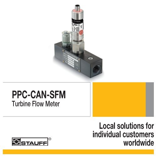
2. Allgemeine GerätebeschreibungDer Sensor PPC-CAN-SFM ist eine Durchflussturbine. Die DurchflussturbinenPPC-CAN-SFM bieten eine Gesamtlösung für dieDurchflussmessung auf Testständen, Maschinenwerkzeugen und anderenAnwendungen an. Der Durchflussmesser wird im hydraulischenKreislauf installiert.Typische Anwendungen sind Produktionsüberprüfung, Inbetriebnahmenoder Entwicklungsprüfungen. Die kompakte Gestaltung ermöglichtdie Montage an Orten mit limitertem Platz. Der Durchflussmesser ist einideales Werkzeug um die Leistung von Pumpen, Motoren, Ventilen undhydrostatischen Getrieben zu messen. Die Messwerte werden über dasstandardisierte serielle Bus-Protokoll CANopen übertragen.Der Sensor PPC-CAN-SFM ist ausschließlich für Messungen mit demMessgerät „<strong>Stauff</strong> PPC-Pad“ vorgesehen. Der Sensor besitzt eine LED,deren Signale den aktuellen Sensorstatus anzeigen.DEUTSCHACHTUNGFühren Sie Messungen mit dem Sensor PPC-CAN-SFM nurmit dem Messgerät „<strong>Stauff</strong> PPC-Pad“ durch, um Schäden amSensor zu vermeiden und korrekte Messwerte zu erhalten.9
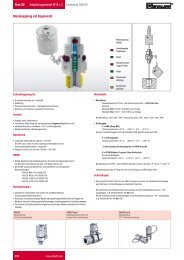
ADBCCSensor PPC-CAN-SFMA LEDB TypenschildC Anschluss DurchflussD SPEEDCON ® -Anschluss Stichleitung / Zuleitung10
3. Bedienung3.1 Anschließen des Sensors/der Sensoren an die MessstelleDie Turbinen haben eingebaute Strömungsberuhiger, sodass die normaleempfohlene Länge von 10 x Ø geradem Schlauch auf 8 x Ø reduziertwerden kann, falls der Platz limitiert ist. Eingangs- und Ausgangsverbindungensollten immer einen ähnlichen Durchmesser wie der Durchflussmesserhaben, um einen Venturi- oder Verengungseffekt zu verhindern.Der Durchflussmesser kann für das periodische-, oder konstante Testenin beiden Richtungen eingesetzt werden.DEUTSCHVORSICHTVerwenden Sie nur für den vorgesehenen Druckbereich zugelasseneSensoren. Informationen über die zulässigen Drückefür die jeweiligen Sensoren finden Sie auf dem Typenschild amSensor.ACHTUNGVerwenden Sie für Messungen nur <strong>Stauff</strong> Anschlusskabel.11
3.2 Zusätzliche AnschlüsseAlle Durchflussmesser haben zwei zusätzliche Anschlüsse auf der oberenFläche, um dem Anwender die Möglichkeit zu bieten, einen Temperatur-und einen Drucksensor anzuschließen. Der Messbereich 15 lpmhat nur den M10x1.3.3 FiltrationEs wird empfohlen einen 25 Mikron Filter (10 Mikron für den PPC-CAN-SFM-015) im hydraulischen Kreislauf, vor dem Durchflussmesser, zuverwenden.3.4 ArbeitsbedinungenDie Reihe wurde für den permanenten Einbau und ständigem Einsatz,bei normalen Arbeitsbedingungen konstruiert.12
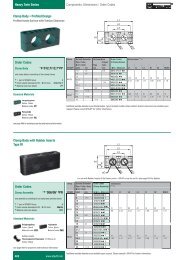
3.5 Anschließen der Anschlusskabel und des AbschlusswiderstandsDieser Abschnitt zeigt Ihnen anhand der Abbildungen Beispiele für dierichtige Kombination der Leitungen. Die Hinweise geben Ihnen an, wasSie dabei beachten müssen.ADEUTSCHBCAnschluss von einem CAN-SensorA Anschlusskabel zum Anschluss an das MessgerätB AbschlusswiderstandC CAN-Sensor13
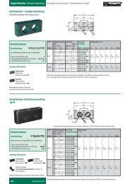
ACHTUNGVerwenden Sie für Messungen nur <strong>Stauff</strong> Anschlusskabel.AABCDAnschluss von mehreren CAN-SensorenA AnschlusskabelB Y-VerteilerC AbschlusswiderstandD CAN-Sensoren14
Achten Sie beim Anschluss von Sensoren der Serie PPC-CAN-SFM darauf, dass sich zwischen dem letzten Sensor am Endeder Busverkabelung und dem Anschlusskabel ein Abschlusswiderstandbefindet.1 Vergewissern Sie sich, dass alle Sensoren fest in den Messstellen verschraubtsind.2 Schrauben Sie den Abschlusswiderstand in den abschließenden Sensor.Befestigen Sie dann das Anschlusskabel am Widerstand.3 Befestigen Sie die Y-Verteiler an den übrigen Sensoren.4 Verbinden Sie die Y-Verteiler mit den Anschlusskabeln.DEUTSCHHinweis zu den Speedcon ® -SchnellverbindungenDas Anbringen an das Anschlusskabel geschieht über Speedcon ® -Schnellverbindungen. Die Schnellverbindung wird zuerst aufgestecktund dann mit einer kleinen Drehung zugedreht (Drehwinkel 180°). BeimAufstecken müssen die Markierungen an den Steckverbindungen zueinanderzeigen.ACHTUNGAchten Sie beim Aufstecken der Schnellverbindung auf dieLeichtgängigkeit und verkanten Sie die Anschlüsse nicht.Überdrehen Sie die Schnellverbindung nicht.15
3.6 Anschließen des Sensors/der Sensoren an das Messgerätund InbetriebnahmeDer einzelne Sensor bzw. das Sensor-Bussystem wird über ein Anschlusskabelan einen der CAN-Anschlüsse des Messgeräts „<strong>Stauff</strong>PPC-Pad“ angeschlossen.Nach dem Einschalten des Messgeräts erfolgt die automatische Erkennungund Initialisierung des Sensors. Ist dieser Vorgang beendet,erscheint der Startbildschirm auf dem Display. Die auftretenden LED-Signaleder CAN-Sensoren dienen der Kennung und der Zustandsanzeige.►►Weitere Informationen zu den LED-Signalen entnehmen Sie derTabelle „LED-Signale am Sensor“.Nach dem Einschaltvorgang können Sie weitere Einstellungen am Messgerät„<strong>Stauff</strong> PPC-Pad“ vornehmen oder mit der Messung beginnen.►►Weitere Informationen zur Bedienung des Messgeräts „<strong>Stauff</strong> PPC-Pad“ entnehmen Sie der Bedienungsanleitung des Messgeräts.16
LED-Signale am SensorLED-Signal am SensorLED leuchtet nichtGrünes LED-Signal blinktschnellGrünes LED-Signal flackertRotes LED-Signal blinkt imSekundentaktRotes LED-Signal blinktschnellRotes LED-Signal leuchtet*BedeutungDer Sensor ist funktionsfähig angeschlossenund liefert Messdaten andas Messgerät.Der Sensor ist funktionsfähigangeschlossen und wurde vom<strong>Stauff</strong> PPC-Pad per Sensor Infoangesprochen.Der Sensor ist funktionsfähig angeschlossenund wird über das <strong>Stauff</strong>PPC-Pad konfiguriert.Der Sensor ist nicht funktionsfähigangeschlossen.Ein Konfigurationsfehler des Sensorsist aufgetreten.Der Sensor ist nicht funktionsfähig,weil die CAN-Schnittstelle wegen fortlaufenderFehler deaktiviert wurde.DEUTSCH* Rote LED-Signale können auch nach Behebung des Fehlers weiterbestehen, da die internen Fehlerzähler erst abgebaut werden müssen.Danach erlischt die Fehlermeldung selbsttätig.17
3.7 Durchflussmessung mit dem Sensor PPC-CAN-SFMDie Durchflussmessungen erfolgen nach den von Ihnen am Messgerät„<strong>Stauff</strong> PPC-Pad“ ausgewählten Einstellungen oder nach den Standard-Einstellungen (Schnellstart-Messung).►►Weitere Informationen zur Durchführung der Messung mit denSensoren und zur Bedienung des Messgeräts „<strong>Stauff</strong> PPC-Pad“ entnehmenSie der Betriebsanleitung des Messgeräts.3.8 KalibrierungAlle Durchflussmesser werden als Standard, bei 21 cSt. kalibriert. SpezialKalibration mit einer anderen Viskosität oder einem gewünschten Durchflusswertist möglich. Wir empfehlen eine Rekalibrierung des Durchflussmessersalle 1-2 Jahre.18
4. AnhangLeitungsspezifikationen / VerlegehinweiseEs wird empfohlen, zum Anschluss von PPC-CAN-SFM-Sensoren nur <strong>Stauff</strong> Anschlusskabel zu benutzen. Dies gewährleisteteine störungsfreie und korrekte Messung.DEUTSCHWeiterführende Literatur zum Industriestandard CANopenCiA 301: CANopen – Application layer and communication profileCiA 305: CANopen – Layer setting services and protocol (LSS)CiA 301, Part 1: Cabling and connector pin assignmentCiA 301, Part 2: Representation of SI units and prefixCiA 301, Part 3: Indicator specificationCiA 404: Device Profile Measuring Devices and Closed-Loop Controllers►►Weitere Informationen zu diesen Industriestandards finden Sie im Internetunter: www.can-cia.orgDatenflussDer PPC-CAN-SFM verwendet den Industriestandard “Deviceprofile measuring devices and closed-loop controllers“, der imCiA Draft Standard 404 festgelegt ist.19
4.1 Technische DatenPPC-CAN-SFM-# 015 060 150 300 600Messbereich1…015 3…060 5...150 8...300 15...600QN (l/min)Genauigkeit1,0 FS 1,0 IR* 1,0 IR* 1,0 IR* 1,0 IR*(± %) FS/IR@ 21cSt.BetriebsdruckPN (bar)350 350 350 350 290Anschluss (A-B) 1/2“BSPDruckabfall∆P max (bar) @(FS)3/4“BSP3/4“BSP1“BSP1,5 1,5 1,5 4 51-1/4“BSPGewicht (g) 1000 2000 2000 2000 2700FS = FullScale (Messbereichsendwert)IR = Indicated Reading (angezeigter Messwert)* = für Messwerte ≥ 15 % FS, bei Messwerten < 15 % Genauigkeit0,15 % FS20
Ansprechzeit (ms) 50Q max (l/min) QN x 1,1Überlastdruck P max (bar) PN x 1,2Anschlüsse:Temperaturmessung (PPC-04/12-TS)Druck (EMA3 Anschluss)Druck (VSTI)M10x1 ORM16x21/4“ BSPPGehäuseAluminiumDichtungFKMMedienberührende TeileAluminium, Stahl, FKMUmgebungstemperatur (°C) -10...+50Lagertemperatur (°C) -20...+80T max Fluid (°C) -20...+90Filtration (μm)25 (10 μm für PPC-CAN-SFM-015)Viskositätsbereich (cSt.)* 10...100DEUTSCH* (kalibriert bei 21 cSt, andere Viskositäten auf Anfrage)PPC-CAN-SFM Durchflussturbine1,0...15/3...60/5...150/8...300/15...600 l/min PPC-CAN-SFM-xxx21
4.2 ZubehörKabel und Adapter CAN0,5 m Kabel PPC-CAN-CAB0.52 m Kabel PPC-CAN-CAB25 m Kabel PPC-CAN-CAB510 m Kabel PPC-CAN-CAB1020 m Kabel PPC-CAN-CAB20Y-Verteiler CAN inkl. 0,3 m Kabel Kabel PPC-CAN-CAB-YAbschlusswiderstandAbschlusswiderstandPPC-CAN-R22
Table of Contents1. Safety Notices 241.1 Proper and intended usage 241.2 Qualified personnel 241.3 Accuracy of the technical documentation 241.4 High pressure applications 251.5 Service and repair 261.6 Cleaning and maintenance information 271.7 Notes on disposal 272. General Description of Sensor 293. Operations 313.1 Connecting the sensor/sensors to the measurement interface313.2 Additional connections 323.3 Filtration 323.4 Operating conditions 323.5 Connecting the connection cable and the terminating resistor 333.6 Connecting the sensor or sensors to the measuringinstrument and starting up 363.7 Flow measurements with the PPC-CAN-SFM sensor 383.8 Calibration 384. Appendix 394.1 Technical Specifications 404.2 Accessories 42ENGLISH23
1. Safety Notices1.1 Proper and intended usageThis measuring instrument ("the instrument") is only approved for use inapplications described in the Operating Instructions. Any other use is notpermitted and can lead to accidents or the destruction of the device. Nonapproveduse will result in the immediate expiration of all guarantee andwarranty claims against the manufacturer.WARNINGSerious malfunctions leading to personal injury or damage toproperty can result when this product is used in applications thatdo not comply with the given specifications or if you disregard theoperating instructions and warning notes.1.2 Qualified personnelThese operating instructions have been written for skilled personnel whoare familiar with the valid regulations and standards relevant to the applicationarea.1.3 Accuracy of the technical documentationThese operating instructions were created with the utmost care and attention.However, we offer no guarantee that the data, graphics anddrawings are correct or complete. This document is subject to alterationwithout notice.24
1.4 High pressure applicationsSelectionDANGERWhen selecting sensors, ensure that their overload pressurewill not be exceeded.The "diesel effect" caused by entrapped air can result in pressurespikes that far exceed the maximum pressure. The operatingpressure of the sensors should be higher than the operatingpressure of the system to be measured.InstallationNOTICEPlease follow the instructions and observe the correct tighteningtorques for fittings and adapters.ENGLISHPlease observe the highest pressures as specified in the cataloguesfor hydraulic fittings or hydraulic hoses.25
1.5 Service and repairContact <strong>Stauff</strong> if you need assistance with repairing or calibrating measuringinstruments.Compatibility with media and substancesWARNINGProducts which come into contact with the medium (substance)are not produced in an oil-free or fat-free environment. Thereforethese product components are not suitable for use in applicationswhich use explosive mixtures of oil and gas (for example,oxygen or compression). This could lead to a dangerof explosion! Only use substances which are compatible withthose components that come into contact with the substance.Please consult with the plant manufacturer or the manufacturerof the substance if you have any questions.26
1.6 Cleaning and maintenance informationOnly clean the sensor with warm water. Do not use a chemical cleanseror alcohol.We recommend that a calibration be carried out every one to two years.1.7 Notes on disposalRecycling in compliance with WEEEPurchasing our product gives you the opportunity to return the device to<strong>Stauff</strong> at the end of its life cycle.The EU Directive 2002/96 EC (WEEE) regulates the return andrecycling of old electrical and electronic devices.As of 13/8/2005, manufacturers of electrical and electronicsequipment in the B2B (business-to-business) sector are obligedto take back and recycle any electrical devices sold after this date for nocharge. After that date, electrical devices must not be disposed of throughthe "normal" waste disposal channels. Electrical equipment must be disposedof and recycled separately. All devices that fall under this directivemust feature this logo.ENGLISH27
Can we be of assistance?<strong>Stauff</strong> offers you the option of returning your old device to us at no extracharge. <strong>Stauff</strong> will then professionally recycle and dispose of your devicein accordance with the applicable law.What do you have to do?Once your device has reached the end of its service life, simply returnit by parcel service (in the box) to <strong>Stauff</strong>. We will then take care of therecycling and disposal. You will incur no costs or suffer any inconvenience.Any questions?If you have any additional questions, please contact us or visit our websiteat www.stauff.com28
2. General Description of SensorThe PPC-CAN-SFM sensor is a flow turbine. The PPC-CAN-SFM flowturbines provide a total solution for measuring flow at test stations, machinetools and other applications. The flow meter is installed within thehydraulic circuit.Typical applications include production inspections, initial commissioningor development testing. Because of its compact design, the flow metercan be installed on-site where space is limited. The flow meter is theperfect tool for measuring the performance of pumps, motors, valves andhydrostatic gears. The measured readings can then be transmitted usingthe standardized CANopen serial bus protocol.The PPC-CAN-SFM sensor should only be used for measurements withthe "<strong>Stauff</strong> PPC-Pad" measuring instrument. The sensor features an LEDwhich can signal the current sensor status.NOTICEBe sure to use the PPC-CAN-SFM sensor only in conjunctionwith the <strong>Stauff</strong> PPC-Pad measuring instrument. This willensure that correct measurements are obtained and that thesensor is not damaged.ENGLISH29
ADBCCPPC-CAN-SFM sensorA LEDB Ratings plateC Flow connectionD SPEEDCON ® connection for spur line or lead-in30
3. Operations3.1 Connecting the sensor/sensors to the measurement interfaceThe turbines feature an integrated current stabilizer. So you can use asmaller tube of 8 times the diameter (instead of the recommended tentimes the diameter of a straight tube) when space is limited. The inputand output connections should always be of the same diameter as theflow meter. This will prevent a narrowing or Venturi effect from takingplace. The flow meter can be used for either periodic or constant testingin both flow directions.CAUTIONOnly use sensors that are approved for the range of pressurethat you are working with. The approved range of pressure fora specific sensor can be found on the sensor's ratings plate.ENGLISHNOTICEOnly <strong>Stauff</strong> connection cables should be used for measuring.31
3.2 Additional connectionsAll flow meters have two additional ports on the upper surface which allowthe user to connect a temperature sensor and a pressure sensor.Only the M10x1 has the 15-lpm measuring range.3.3 FiltrationWe recommend using a 25-micron filter (or a 10-micron filter for thePPC-CAN-SFM-015) when using the flow meter within a hydraulic circuit.3.4 Operating conditionsThis product series is designed for permanent installation and permanentuse under normal operating conditions.32
3.5 Connecting the connection cable and the terminating resistorThis section gives illustrated examples of correct cable combinations.The notices highlight information of particular importance.ABCENGLISHConnecting a single CAN sensorA Cable for connecting to the measurement instrumentB Terminating resistorC CAN sensorNOTICEOnly <strong>Stauff</strong> connection cables should be used for measuring.33
AABCDConnecting multiple CAN sensorsA Connection cableB Y junctionC Terminating resistorD CAN sensors34
When connecting multiple sensor from the PPC-CAN-SFMseries, be sure that a terminating resistor is used on the connectioncable before the last sensor at the end of the bus.1 Make sure that all sensors are securely screwed in to their measurementinterfaces.2 Screw the terminating resistor into the final sensor. Then fasten theconnection cable to the resistor.3 Connect the remaining sensors using Y splitters.4 Connect the Y splitters with the connection cables.Notice concerning the Speedcon ® quick connectionsThe connection cable is attached using Speedcon ® quick connection interfaces.The quick connection itself is initially plugged in and then turnedwith a slight turn (a 180° rotation). When plugging in, the marks on theconnector must be aligned with each other.ENGLISHNOTICEWhen connecting the quick connection, be sure that the connectionscan move freely and are not jammed in any way.Make sure that you do not over-turn the quick connection.35
3.6 Connecting the sensor or sensors to the measuring instrumentand starting upUsing a connection cable, the individual sensor or sensor bus systemshould be connected to one of the CAN ports on the <strong>Stauff</strong> PPC-Padmeasuring instrument.After the measuring instrument is turned on, the sensor is automaticallydetected and initialized. The start screen appears on the display afterthis process has ended. The LED signals on the CAN sensors are usedfor identification and status display.►►Additional information about the LED signals can be found in the"LED signals on the sensor" table.After the boot-up process, you can make further setting changes on the<strong>Stauff</strong> PPC-Pad measuring instrument or you can begin measuring.►►Additional information about operating the <strong>Stauff</strong> PPC-Padmeasuring instrument can be found in the instrument's operating instructions.36
LED signals on the sensorLED signal on the sensorLED is not illuminatedGreen LED is flashing quicklyGreen LED is flickeringRed LED is blinking once persecondRed LED is flashing quicklyRed LED is illuminated*MeaningThe sensor has a functional connectionand is delivering measurementsto the measuring instrument.The sensor has a functional connectionand is being addressed via sensorinfo by the <strong>Stauff</strong> PPC-Pad.The sensor has a functional connectionand is being configured by the<strong>Stauff</strong> PPC-Pad.The sensor does not have a functioningconnection.A sensor configuration error has occurred.The sensor is not functioning becausethe CAN interface has been deactivateddue to continued errors.ENGLISH* A red LED signal may be displayed after the error has been fixed. Butonce the internal error counter has decremented itself, the LED will goout.37
3.7 Flow measurements with the PPC-CAN-SFM sensorThe flow will be measured according to the settings which you have selectedon the <strong>Stauff</strong> PPC-Pad measuring instrument or according to thedefault settings (for a quick-start measurement).►►Additional information on taking measurements with the sensors andoperating the <strong>Stauff</strong> PPC-Pad measuring instrument can be found inthe instrument's operating instructions.3.8 CalibrationAll flow meters are calibrated by default to 21 cSt. Custom calibrationsbased on other viscosities or specific flow values are also possible. Werecommend that the flow meter be re-calibrated every one to two years.38
4. AppendixCable specifications / routing noticeWe recommend that you use only original <strong>Stauff</strong> connectioncables when connecting PPC-CAN-SFM sensors. This will guaranteethat your measurements are correct and free from errors.Further reading about the CANopen industrial standardCiA 301: CANopen – Application layer and communication profileCiA 305: CANopen – Layer setting services and protocol (LSS)CiA 301, Part 1: Cabling and connector pin assignmentCiA 301, Part 2: Representation of SI units and prefixCiA 301, Part 3: Indicator specificationCiA 404: Device Profile Measuring Devices and Closed-Loop Controllers►►You can find more information about these industrial standards onthe Internet at www.can-cia.orgENGLISHData flowThe PPC-CAN-SFM uses the "Device profile measuring devicesand closed-loop controllers" industrial standard, as specified inthe CiA Draft Standard 404.39
4.1 Technical SpecificationsPPC-CAN-SFM-# 015 060 150 300 600Flow measuring range 1…015 3…060 5...150 8...300 15...600QN (l/min)Accuracy1.0 FS 1.0 IR* 1.0 IR* 1.0 IR* 1.0 IR*(± %) FS/IR@ 21cSt.Operating pressurePN (bar)350 350 350 350 290Ports (A - B) 1/2"BSPPressure drop∆P max (bar) @ (FS)3/4"BSP3/4"BSP1“BSP1.5 1.5 1.5 4 51-1/4"BSPWeight (g) 1000 2000 2000 2000 2700FS = Full scale (upper range value)IR = Indicated reading (measured value)* = for readings ≥ 15 % FS, for readings < 15 % Accuracy 0.15 % FS40
Response time (ms) 50Q max (l/min) QN x 1.1Overload pressure P max (bar) PN x 1.2Ports:Temperature port (PPC-04/12-TS)Pressure port (EMA3 Fitting)Pressure port (VSTI)HousingSealingParts in contact with mediaM10x1 ORM16x21/4" BSPPAluminiumFKMAluminium, steel, FKMAmbient temperature (°C) -10...+50Storage temperature (°C) -20...+80T max Fluid (°C) -20...+90Filtration (µm)25 (10 μm for PPC-CAN-SFM-015)Viscosity range (cSt.) 10...100ENGLISH* (calibrated at 21 cSt, other viscosities on request)PPC-CAN-SFM flow meter1.0...15/3...60/5...150/8...300/15...600 l/min PPC-CAN-SFM-xxx41
4.2 AccessoriesCable and adapter CAN0,5 m Cable PPC-CAN-CAB0.52 m Cable PPC-CAN-CAB25 m Cable PPC-CAN-CAB510 m Cable PPC-CAN-CAB1020 m Cable PPC-CAN-CAB20CAN Y junction, including 0.3 m cable Cable PPC-CAN-CAB-YTerminating ResistorTerminating ResistorPPC-CAN-R42
Sommaire1 Consignes de sécurité 441.1 Utilisation conforme 441.2 Personnel spécialisé 441.3 Exactitude de la documentation technique 441.4 Applications haute pression 451.5 Service après-vente / réparation 461.6 Nettoyage/consignes d'entretien 471.7 Remarques concernant la mise au rebut 472. Description général de l'appareil 493. Utilisation 513.1 Raccordement du capteur/des capteurs au point de mesure 513.2 Raccords supplémentaires 523.3 Filtration 523.4 Conditions de travail 523.5 Raccordement du câble de liaison et de la résistancede terminaison 533.6 Raccordement du capteur/des capteurs sur l'appareilde mesure et mise en service 563.7 Mesure de débit à l'aide du capteur PPC-CAN-SFM 583.8 Etalonnage 584. Annexe 594.1 Caractéristiques techniques 604.2 Accessoires 62FRANCAIS43
1 Consignes de sécurité1.1 Utilisation conformeL'appareil n'est destiné qu'aux applications décrites dans ce mode d'emploi.Toute autre utilisation est interdite et peut conduire à des accidentsou la destruction de l'appareil. De telles applications auront pour conséquenceune extinction immédiate des garanties et des droits vis-à-vis dufabricant.AVERTISSEMENTUne utilisation du produit sélectionné en dehors de la spécificationou le non-respect des consignes de manipulation et d'avertissementpeuvent conduire à des dysfonctionnements si gravesqu'il peut en résulter des dommages corporels ou matériels.1.2 Personnel spécialiséCe mode d'emploi s'adresse au personnel spécialisé et formé, familiariséavec les directives et normes en vigueur dans le domaine d'emploi.1.3 Exactitude de la documentation techniqueCe mode d'emploi a été élaboré avec grand soin. Aucune garantie n'estassurée quant à l'exactitude et à l'exhaustivité des données, figures etdessins qu'il comporte. Sous réserve de modifications.44
1.4 Applications haute pressionSélectionDANGERLors de la sélection des capteurs, veiller à ne pas dépasser lapression de surcharge.La formation de poches d'air peut conduire par "effet Diesel" àdes pointes de pression pouvant largement dépasser la pressionde surcharge. La pression de service du capteur doit êtresupérieure à la pression de service régnant dans le systèmeà mesurer.MontageAVISVeuillez suivre les instructions et respecter les couples de serragedes raccords ou adaptateurs utilisés.Pour les raccords hydrauliques ou les flexibles hydrauliques,veuillez respecter les pressions maximum indiquées dans lescatalogues.FRANCAIS45
1.5 Service après-vente / réparationPour les travaux de réparation ou d'étalonnage des appareils de mesure,veuillez vous adresser à <strong>Stauff</strong>.Compatibilité avec les fluidesAVERTISSEMENTLes produits en contact avec les fluides ne sont pas fabriquéssans huile ni sans graisse. Pour les applications pouvant générerun mélange explosif d'huile ou d'huile et de gaz (par ex.oxygène ou compression), ces produits ne doivent donc pasêtre utilisés (danger d'explosion !). N'utilisez que des fluidescompatibles avec les pièces en contact avec ceux-ci. Si vousavez des questions, contactez le fabricant de l'installation ou lefabricant du fluide utilisé.46
1.6 Nettoyage/consignes d'entretienVeuillez nettoyer le capteur uniquement avec de l'eau chaude. N'utilisezaucun produit nettoyant chimique ni alcool.Un étalonnage régulier tous les 1 à 2 ans est conseillé.1.7 Remarques concernant la mise au rebutRecyclage selon DEEEEn achetant notre produit, vous avez la possibilité de rendre l'appareil à<strong>Stauff</strong> lorsqu'il est en fin de vie.La directive DEEE (Directive CE 2002/96 CE) réglemente leretour et le recyclage des équipements électriques. Dans lecommerce interentreprises, les fabricants d'appareils électriquesont l'obligation depuis le 13/08/2005 de reprendre gratuitementles appareils électriques vendus après cette date et de les recycler.Depuis cette date, il est interdit de mettre les appareils électriquesaux déchets "normaux". Les appareils électriques doivent être recycléset éliminés séparément. Tous les appareils auxquels s'applique cette directiveportent ce logo.FRANCAIS47
Que pouvons-nous faire pour vous ?Dans ce contexte, <strong>Stauff</strong> vous offre la possibilité de nous rendre sansfrais votre ancien appareil. <strong>Stauff</strong> recyclera et éliminera ensuite cet appareilselon les règles de l'art et en respect de la loi en vigueur.Que devez-vous faire ?Lorsque votre appareil est en fin de vie, envoyez-le par colis postal (dansun carton) au <strong>Stauff</strong>. Nous assumons ensuite toutes les mesures derecyclage et d'élimination nécessaires. Ceci ne vous engage à aucunfrais ni désagréments.Avez-vous d'autres questions ?Si vous avez d'autres questions, contactez-nous ou rendez-vous surwww.stauff.com.48
2. Description général de l'appareilLe capteur PPC-CAN-SFM est une turbine débitmétrique. Les turbinesdébitmétriques PPC-CAN-SFM offrent une solution globale pour mesurerle débit sur bancs d'essai, machines-outils et autres applications. Ledébitmètre s'installe sur le circuit hydraulique.Les applications typiques se trouvent dans le contrôle de production, lesmises en service ou les contrôles de développement. La forme compactepermet de le monter dans des endroits où la place est limitée. Le débitmètreest un outil idéal pour mesurer la performance des pompes, moteurs,vannes et engrenages hydrostatiques. Les valeurs de mesure sonttransmises à l'aide du protocole normalisé de bus série CANopen.Le capteur PPC-CAN-SFM est conçu exclusivement pour les mesures àl'aide de l'appareil " <strong>Stauff</strong> PPC-Pad". Le capteur possède une diode lumineusedont les signaux affichent l'état actuel du capteur.AVISN'effectuez les mesures avec le capteur PPC-CAN-SFMqu'avec l'appareil de mesure "<strong>Stauff</strong> PPC-Pad", afin d'évitertout dommage sur le capteur et afin d'obtenir des mesurescorrectes.FRANCAIS49
ADBCCCapteur PPC-CAN-SFMA DELB Plaque signalétiqueC Raccord débitD Prise SPEEDCON ® câble de branchement/alimentation50
3. Utilisation3.1 Raccordement du capteur/des capteurs au point de mesureLes turbines possèdent des tranquilliseurs d'écoulement intégrés, desorte que la longueur normale conseillée de 10 x Ø de tube droit peutêtre réduit à 8 x Ø si la place est limitée. Les raccords d'entrée et de sortiedoivent toujours offrir un diamètre similaire au débitmètre afin d'éviterun effet Venturi ou d'étranglement. Le débitmètre peut être utilisé pourles essais périodiques ou permanents, dans les deux sens.ATTENTIONN'utilisez que les capteurs admissibles pour les étendues depression prévues. Sur la plaque signalétique du capteur, voustrouverez des informations sur les pressions admissibles dechaque capteur.AVISPour les mesures, utilisez exclusivement des câbles de raccordement<strong>Stauff</strong>.FRANCAIS51
3.2 Raccords supplémentairesTous les débitmètres ont deux raccords supplémentaires en surface supérieursafin d'offrir à l'utilisateur la possibilité de raccorder un capteur detempérature et un capteur de pression. La plage de mesure 15 lpm nepossède que le M10x1.3.3 FiltrationIl est recommandé d'utiliser un filtre 25 micron (10 micron pour le PPC-CAN-SFM-015) dans le circuit hydraulique, en amont du débitmètre.3.4 Conditions de travailCette série a été construite pour être montée en permanence et utiliséeen permanence, dans les conditions normales de travail.52
3.5 Raccordement du câble de liaison et de la résistance determinaisonCette section vous montre à l'aide des figures suivantes des exemplespour associer correctement les conducteurs. Les remarques vous indiquentce qu'il faut alors respecter.ABCRaccordement d'un capteur CANA Câble de raccordement sur l'appareil de mesureB Résistance de terminaisonC Capteur CANFRANCAIS53
AVISPour les mesures, utilisez exclusivement des câbles de raccordement<strong>Stauff</strong>.AABCDRaccordement de plusieurs capteurs CANA Câble de raccordementB Répartiteur YC Résistance de terminaisonD Capteurs CAN54
Lors du raccordement des capteurs de la série PPC-CAN-SFM,veillez à ce qu'une résistance de terminaison soit placée entre ledernier capteur situé en fin de câblage bus et le câble de raccordement.1 Assurez-vous que tous les capteurs soient fermement vissés dans lespoints de mesure.2 Vissez la résistance de terminaison dans le capteur situé à l'extrémité.Fixez ensuite le câble de raccordement sur la résistance.3 Fixez le répartiteur Y sur les capteurs restants.4 Raccordez le répartiteur Y sur les câbles de raccordement.Remarque sur les raccords rapides Speedcon ®La connexion sur le câble de raccordement s'effectue à l'aide de connecteursrapides Speedcon ® . Le raccord rapide est d'abord enfiché, puistourné par un petit mouvement de rotation (angle de rotation 180°). Lorsde l'enfichage, les repères situés sur les connecteurs doivent être faceà face.AVISLorsque vous enfichez le raccord rapide, veillez à ce cela s'effectuesans efforts et ne pliez pas les connexions. Ne pas tournerexcessivement la connexion rapide.FRANCAIS55
3.6 Raccordement du capteur/des capteurs sur l'appareil demesure et mise en serviceLe capteur unique ou le circuit de capteurs sur bus se connecte par uncâble de raccordement sur l'une des prises CAN de l'appareil de mesure"<strong>Stauff</strong> PPC-Pad".Après mise sous tension de l'appareil de mesure, le capteur est automatiquementdétecté et initialisé. Une fois cette procédure terminée, l'écrande départ s'affiche à l'écran. Les signaux de diode lumineuse émis surles capteurs CAN servent à l'identification et à l'affichage de l'état.►►Vous trouverez d'autres informations relatives aux signaux émis parles diodes dans le tableau "Signaux des DEL sur le capteur".Après la phase de mise en service, vous pouvez effectuer d'autresréglages sur l'appareil de mesure "<strong>Stauff</strong> PPC-Pad" ou commencer àmesurer.►►Vous trouverez d'autres informations sur l'utilisation de l'appareil demesure "<strong>Stauff</strong> PPC-Pad" dans le mode d'emploi de l'appareil demesure.56
Signaux des DEL sur le capteurSignal de la DEL sur lecapteurDEL éteinteLa diode clignote verte rapidementLa diode s'allume en vertvacillanteLa diode clignote rouge enbattant la secondeLa diode clignote rougerapidementLa diode s'allume en rouge*SignificationLe capteur est raccordé de façonopérationnelle et délivre les mesuresà l'appareil.Le capteur est raccordé et fonctionnelet a été interrogé par le <strong>Stauff</strong> PPC-Pad, par info capteur.Le capteur est raccordé et fonctionnel,il est en cours de configuration par le<strong>Stauff</strong> PPC-Pad.Le capteur n'est pas branché de façonopérationnelle.Une erreur de configuration du capteurest survenue.Le capteur n'est pas opérationnel carl'interface CAN a été désactivée pourraison d'erreur permanente.* Les signaux de diode rouge peuvent perdurer même après éliminationde l'erreur, car les compteurs internes d'erreur doivent d'abord être démontés.Le message d'erreur s'éteint ensuite de lui-même.FRANCAIS57
3.7 Mesure de débit à l'aide du capteur PPC-CAN-SFMLes mesures de débit s'effectuent selon les réglages que vous avez effectuéssur l'appareil de mesure "<strong>Stauff</strong> PPC-Pad" ou selon les réglagesstandard (mesure à démarage rapide).►►Vous trouverez de plus amples informations pour effectuer la mesureavec les capteurs et pour manipuler l'appareil de mesure "<strong>Stauff</strong>PPC-Pad" dans le mode d'emploi de l'appareil.3.8 EtalonnageTous les débitmètres sont calibrés en standard à 21 cSt. Un étalonnagespécial à une autre viscosité ou une valeur de débit désirée est égalementpossible. Un réétalonnage régulier du débitmètre tous les 1 à 2 ansest conseillé.58
4. AnnexeSpécification des conducteurs / conseils de poseIl est recommandé de n'utiliser que des câbles de raccordement<strong>Stauff</strong> pour effectuer le branchement des capteurs PPC-CAN-SFM. Ceci assure une mesure correcte et non parasitée.Ouvrages connexes sur le standard industriel CANopenCiA 301 : CANopen – Application layer and communication profileCiA 305 : CANopen – Layer setting services and protocol (LSS)CiA 301, Part 1 : Cabling and connector pin assignmentCiA 301, Part 2 : Representation of SI units and prefixCiA 301, Part 3 : Indicator specificationCiA 404 : Device Profile Measuring Devices and Closed-Loop Controllers►►Vous trouverez de plus amples informations au sujet de ces standardsindustriels sur Internet à l'adresse : www.can-cia.orgFux de donnéesLe PPC-CAN-SFM utilise le standard industriel "Device profilemeasuring devices and closed-loop controllers", lequel est définidans le projet de norme CiA 404.FRANCAIS59
4.1 Caractéristiques techniquesPPC-CAN-SFM-# 015 060 150 300 600Plage de mesure debit 1…015 3…060 5...150 8...300 15...600QN (l/min)Précision1,0 FS 1,0 IR* 1,0 IR* 1,0 IR* 1,0 IR*(± %) FS/IR@ 21cSt.Pression de fonctionnement 350 350 350 350 290PN (bar)Raccord (A - B) 1/2"BSPPerte de charge∆P max (bar) @(FS)3/4"BSP3/4"BSP1"BSP1,5 1,5 1,5 4 51-1/4"BSPPoids (g) 1000 2000 2000 2000 2700FS = FullScale (pleine échelle)IR = Indicated Reading (mesure affichée)* = pour mesures ≥ 15 % PE, sur les mesures < 15 % précision 0,15 %PE60
Temps de réponse (ms) 50Q max (l/min) QN x 1,1Pression de surcharge P max (bar) PN x 1,2RaccordMesure de Température (PPC-04/12-TS)Pression (EMA3 Raccord)Pression (VSTI)BoîtierJointPièces en contact avec le fluideM10x1 OUM16x21/4" BSPPaluminiumFKMAluminium, acier, FKMTempérature ambiante (°C) -10...+50Température de stockage (°C) -20...+80T max fluide (°C) -20...+90Filtre (µm)25 (10 μm pourPPC-CAN-SFM-015)Plage de viscosité (cSt.) 10...100* calibrés à 21 cSt., autres viscosités sur demandeDébitmètre à turbine PPC-CAN-SFM1,0...15/3...60/5...150/8...300/15...600 l/min PPC-CAN-SFM-xxxFRANCAIS61
4.2 AccessoiresCâble et adaptateur CAN0,5 m Cable PPC-CAN-CAB0.52 m Cable PPC-CAN-CAB25 m Cable PPC-CAN-CAB510 m Cable PPC-CAN-CAB1020 m Cable PPC-CAN-CAB20Répartiteur Y CAN avec 0.3 m de câble Cable PPC-CAN-CAB-YÉtats de resistanceTerminating ResistorPPC-CAN-R62
Contenuto1. Norme di sicurezza 641.1 Utilizzo conforme alla finalità d'uso 641.2 Personale tecnico 641.3 Correttezza della documentazione tecnica 641.4 Applicazioni ad alta pressione 651.5 Assistenza/Riparazione 661.6 Pulizia/Istruzioni per la manutenzione 671.7 Norme per lo smaltimento 672. Descrizione generale dell'apparecchio 69ITALIANO3. Utilizzo 713.1 Collegamento del sensore/dei sensori al punto di misura 713.2 Altri collegamenti 723.3 Filtrazione 723.4 Condizioni di lavoro 723.5 Collegare il cavo di raccordo e la resistenza terminale 733.6 Collegamento del sensore/dei sensori allo strumento dimisura e messa in funzione 763.7 Misurazione della portata con il sensore PPC-CAN-SFM 783.8 Calibrazione 784. Allegato 794.1 Dati Tecnici 804.2 Accessori 8263
1. Norme di sicurezza1.1 Utilizzo conforme alla finalità d'usoL'apparecchio è adatto esclusivamente per le applicazioni descritte nelleistruzioni per l'uso. Un impiego diverso è da considerarsi inammissibilee potrebbe provocare incidenti o la distruzione dell'apparecchio. Taliutilizzi comportano l'annullamento immediato della garanzia nei confrontidel produttore.AVVERTENZAUn utilizzo del prodotto che non rispetti le specifiche indicateovvero la mancata osservanza delle istruzioni per l’uso e degliavvertimenti potrebbero causare problemi di funzionamento chea loro volta potrebbero mettere a rischio persone e cose.1.2 Personale tecnicoLe presenti istruzioni per l’uso si rivolgono a personale specializzato cheabbia acquisito familiarità con le disposizioni e le norme del settore.1.3 Correttezza della documentazione tecnicaLe presenti istruzioni per l’uso sono state redatte con la massima cura. Sideclina ogni responsabilità per quanto riguarda la correttezza e la completezzadi dati, figure e disegni. Con riserva di modifiche.64
1.4 Applicazioni ad alta pressioneSelezionePERICOLOQuando si scelgono i sensori, non bisogna superare la pressionedi sovraccarico.Le inclusioni di aria potrebbero causare un "effetto diesel", conil conseguente incremento della pressione di sovraccarico. Lapressione d'esercizio del sensore deve essere superiore allapressione d'esercizio presente nel sistema da misurare.ITALIANOMontaggioAVVISOAttenersi alle avvertenze e rispettare i momenti torcenti correttiper gli avvitamenti o l'adattatore utilizzati.Nel caso degli avvitamenti idraulici o dei tubi flessibili idraulici,prestare attenzione alle pressioni massime indicate nei cataloghi.65
1.5 Assistenza/RiparazionePer la riparazione o la calibrazione degli strumenti di misura, rivolgersia <strong>Stauff</strong>.Compatibilità con le sostanzeAVVERTENZAI prodotti che entrano in contatto con i mezzi non sono esentida lubrificazione o ingrassaggio. Evitare pertanto di utilizzarequesti prodotti in applicazioni in cui si possa generare una miscelaesplosiva di olio o di olio-gas (ad esempio ossigeno ocompressione) (pericolo di esplosione!) Utilizzare esclusivamentesostanze compatibili con i componenti che vi entranoin contatto. Per ulteriori informazioni, rivolgersi al costruttoredell'impianto o al produttore del mezzo utilizzato.66
1.6 Pulizia/Istruzioni per la manutenzionePulire il sensore solo con acqua calda, Non utilizzare detergenti chimicio alcool.Si consiglia di eseguire una calibrazione regolare ogni 1-2 anni.1.7 Norme per lo smaltimentoRiciclaggio secondo WEEEAcquistando un nostro prodotto, il cliente ha la possibilità di restituire a<strong>Stauff</strong> l'apparecchio al termine del proprio ciclo di vita.La direttiva WEEE (direttiva UE 2002/96 CE) regola la restituzionee il riciclaggio delle apparecchiature elettriche ed elettroniche.Nel settore B2B (Business to Business), a decorrere dal13.8.2005 i produttori di apparecchiature elettriche ed elettronichesono obbligati a ritirare e a riciclare gratuitamente le apparecchiatureelettriche ed elettroniche vendute dopo questa data. Le apparecchiatureelettriche ed elettroniche non devono pertanto essere più inserite nelciclo „normale“ dei rifiuti. Gli apparecchi elettrici devono essere riciclati esmaltiti separatamente. Tutti gli apparecchi che rientrano in questa direttivasono contrassegnati con questo logo.ITALIANO67
Che cosa possiamo fare per Lei?<strong>Stauff</strong> offre ai suoi clienti la possibilità di restituire gratuitamente le apparecchiatureormai obsolete. <strong>Stauff</strong> provvederà quindi a riciclare e smaltirele apparecchiature secondo la normativa vigente.Che cosa deve fare Lei?Una volta che le apparecchiature hanno completato il loro ciclo di vita,basta inviarle in un pacco (cartone) alla <strong>Stauff</strong>. Sarà poi nostra cura adottaretutte le misure necessarie per il riciclaggio e lo smaltimento. Senzacosti né complicazioni da parte Sua.Altre domande?Per maggiori informazioni, è possibile contattarci direttamente oppure visitareil nostro sito all'indirizzo www.stauff.com.68
2. Descrizione generale dell'apparecchioIl sensore PPC-CAN-SFM è un misuratore di portata a turbina. I misuratoridi portata a turbina PPC-CAN-SFM rappresentano una soluzionecompleta per la misurazione della portata su espositori prove clienti,macchine utensili e altre applicazione. Il flussimetro viene installato nelcircuito idraulico.Applicazioni tipiche sono il controllo della produzione, la messa in servizioo controlli di sviluppo. La struttura compatta consente il montaggio inluoghi con spazio limitato. Il flussimetro è uno strumento ideale per misurarela potenza di pompe, motori, valvole e trasmissioni idrostatiche.I valori di misura vengono trasferiti tramite il protocollo bus seriale standardizzatoCANopen.Il sensore PPC-CAN-SFM è destinato esclusivamente alla misurazionecon lo strumento "<strong>Stauff</strong> PPC-Pad". Il sensore dispone di un LED i cuisegnali indicano lo stato corrente del sensore.ITALIANOAVVISOEseguire le misurazioni con il sensore PPC-CAN-SFM solocon lo strumento di misura "<strong>Stauff</strong> PPC-Pad". In questo modosi evitano danni al sensore e si ottengono valori di misuracorretti.69
ADBCCSensore PPC-CAN-SFMA LEDB TarghettaC Collegamento portataD Collegamento SPEEDCON ® cavo di derivazione/tubazione70
3. Utilizzo3.1 Collegamento del sensore/dei sensori al punto di misuraLe turbine hanno stabilizzatori di portata integrati che consentono di ridurrela lunghezza consigliata da 10 x Ø flessibile diritto a 8 x Ø flessibilediritto, qualora lo spazio a disposizione sia limitato. I collegamenti d'ingressoe d'uscita devono sempre avere un diametro simile a quello delflussimetro; in questo modo si evita l'effetto Venturi o di restringimento.Il flussimetro può essere utilizzato per il collaudo periodico o costante inentrambe le direzioni.ITALIANOATTENZIONEUtilizzare esclusivamente sensori omologati per i vari intervallidi pressione. Per maggiori informazioni sulle pressioni consentiteper i diversi sensori, fare riferimento alla targhetta presentesul sensore.AVVISOPer le misurazioni, impiegare esclusivamente cavi di collegamento<strong>Stauff</strong>.71
3.2 Altri collegamentiTutti i flussimetri dispongono di due collegamenti supplementari sulla superficiesuperiore in modo da offrire all'utente la possibilità di collegareun sensore di temperatura e un sensore di pressione. Solo M10x1 ha ilcampo di misura 15 lpm.3.3 FiltrazioneSi consiglia di utilizzare un filtro da 25 micron (10 micron per PPC-CAN-SFM-015) nel circuito idraulico, a monte del flussimetro.3.4 Condizioni di lavoroQuesta serie è stata costruita per il montaggio permanente e l'impiegocontinuo in condizioni di lavoro normali.72
3.5 Collegare il cavo di raccordo e la resistenza terminaleLe figure di questo capitolo forniscono esempi inerenti la giusta combinazionedei cavi. Le avvertenze richiamano invece l'attenzione sui puntia cui prestare attenzione.AITALIANOBCCollegamento di un sensore CANA Cavo di raccordo al collegamento sullo strumento di misuraB Resistenza terminaleC Sensore CAN73
AVVISOPer le misurazioni, impiegare esclusivamente cavi di collegamento<strong>Stauff</strong>.AABCDCollegamento di più sensori CANA Cavo di collegamentoB Ripartitore YC Resistenza terminaleD Sensori CAN74
Durante il collegamento dei sensori della serie PPC-CAN-SFM,assicurarsi che tra l'ultimo sensore alla fine del cablaggio bus e ilcavo di raccordo sia presente una resistenza terminale.1 Accertarsi che tutti i sensori siano avvitati saldamente ai punti di misura.2 Avvitare la resistenza terminale nel sensore finale. Fissare quindi ilcavo di raccordo alla resistenza.3 Fissare il ripartitore Y agli altri sensori.4 Collegare il ripartitore Y ai cavi di raccordo.ITALIANONota sugli attacchi rapidi Speedcon ®L'applicazione sul cavo di raccordo avviene mediante gli attacchi rapidiSpeedcon ® . L'attacco rapido viene dapprima innestato, quindi ruotatocon una piccola rotazione (angolo di rotazione di 180°). Durante il montaggio,i contrassegni sui connettori devono essere contrapposti.AVVISODurante il montaggio dell'attacco rapido, verificare la mobilitàevitando di inclinare i raccordi. Non serrare eccessivamentel'attacco rapido.75
3.6 Collegamento del sensore/dei sensori allo strumento di misurae messa in funzioneIl singolo sensore o il sistema bus di sensori viene collegato tramite uncavo di collegamento a uno dei collegamenti CAN dello strumento di misura"<strong>Stauff</strong> PPC-Pad".Dopo l'accensione dello strumento di misura avviene il riconoscimentoautomatico e l'inizializzazione del sensore. Una volta completato questoprocesso, sul display compare la schermata di avvio. I segnali LEDdei sensori CAN consentono l'identificazione e l'indicazione dello stato.►►Per maggiori informazioni sui segnali LED, fare riferimento alla tabella"Segnali LED sul sensore".Dopo la procedura di accensione, è possibile eseguire altre impostazionisullo strumento di misura "<strong>Stauff</strong> PPC-Pad" oppure iniziare la misurazione.►►Per maggiori informazioni sull'utilizzo dello strumento di misura"<strong>Stauff</strong> PPC-Pad", fare riferimento alle istruzioni per l'uso inerenti lostrumento di misura.76
Segnali LED sul sensoreSegnale LED sul sensoreIl LED non si accendeIl segnale LED verde lampeggiavelocementeIl segnale LED verde sfarfallaIl segnale LED rosso lampeggiaad intervalli di secondi.Il segnale LED rosso lampeggiavelocementeIl segnale LED rosso siaccende*SignificatoIl sensore è collegato correttamente efornisce i dati di misura allo strumentodi misura.Il sensore è collegato correttamenteed è stato interrogato da <strong>Stauff</strong> PPC-Pad per Sensor InfoIl sensore è collegato correttamentee viene configurato tramite <strong>Stauff</strong>PPC-Pad.Il sensore non è collegato correttamente.Si è verificato un errore di configurazionedel sensore.Il sensore non funziona in quantol'interfaccia CAN è stata disattivata acausa di errori progressivi.ITALIANO* I segnali LED rossi possono presentarsi anche dopo l'eliminazionedell'errore in quanto il contatore di errori interno deve essere precedentementesmontato. Dopo di che il messaggio di errore scompareautomaticamente.77
3.7 Misurazione della portata con il sensore PPC-CAN-SFMLe misurazioni della portata avvengono in base alle impostazioni selezionatesullo strumento di misura "<strong>Stauff</strong> PPC-Pad" oppure in base alle impostazionipredefinite (misurazione avvio rapido).►►Per maggiori informazioni sull'esecuzione della misurazione con isensori e sull'utilizzo dello strumento di misura "<strong>Stauff</strong> PPC-Pad",fare riferimento alle istruzioni per l'uso inerenti lo strumento di misura.3.8 CalibrazioneTutti i flussimetri vengono calibrati di serie a 21 cSt. Possibilità di calibrazionespeciale con una viscosità diversa o un valore di portata desiderato.Si consiglia di eseguire una ricalibrazione del flussimetro ogni1-2 anni.78
4. AllegatoSpecifiche dei cavi / Norme per la posaPer collegare i sensori PPC-CAN-SFM si consiglia di utilizzaresolo cavi di collegamento <strong>Stauff</strong>. In questo modo si garantisceuna misurazione precisa ed accurata.ITALIANOLetteratura di riferimento inerente lo standard industriale CANopenCiA 301: CANopen – Application layer and communication profileCiA 305: CANopen – Layer setting services and protocol (LSS)CiA 301, Part 1: Cabling and connector pin assignmentCiA 301, Part 2: Representation of SI units and prefixCiA 301, Part 3: Indicator specificationCiA 404: Device Profile Measuring Devices and Closed-Loop Controllers►►Per maggiori informazioni su questi standard industriali, digitare inInternet l'indirizzo: www.can-cia.orgFlusso di datiIl sensore PPC-CAN-SFM utilizza lo standard industriale"Device profile measuring devices and closed-loop controllers",fissato in CiA Draft Standard 404.79
4.1 Dati TecniciPPC-CAN-SFM-# 015 060 150 300 600Campo di misura 1…015 3…060 5...150 8...300 15...600QN (l/min)Precisione1,0 FS 1,0 IR* 1,0 IR* 1,0 IR* 1,0 IR*(± %) FS/IR@ 21cSt.Pressione d'esercizioPN (bar)350 350 350 350 290Collegamento (A-B) 1/2“BSPCaduta di pressione∆P max (bar) @(FS)3/4“BSP3/4“BSP1“BSP1,5 1,5 1,5 4 51-1/4“BSPPeso (g) 1000 2000 2000 2000 2700FS = FullScale (valore del campo di misura)IR = Indicated Reading (valore di misura visualizzato)* = per i valori misurati ≥ 15 % FS, con valori misurati < 15 % Precisione0,15 % FS80
Tempo di reazione (ms) 50Q max (l/min) QN x 1,1Pressione di sovraccarico P max PN x 1,2(bar)Collegamenti:Misurazione della temperatura(PPC-04/12-TS)Pressione (collegamento EMA3)Pressione (VSTI)CustodiaGuarnizioneParti a contatto con il mezzoM10x1 ORM16x21/4“ BSPPAlluminioFKMAlluminio, acciaio, FKMTemperatura ambiente (°C) -10...+50Temperatura di immagazzinamento-20...+80(°C)T max Fluido (°C) -20...+90Filtrazione (μm)25 (10 μm perPPC-CAN-SFM-015)Campo viscosità (cSt.)* 10...100ITALIANO* (calibrato su 21-26 cSt., altre viscosità a richiesta)Misurazione di flusso a turbinaPPC-CAN-SFM1,0...15/3...60/5...150/8...300/15...600 l/min PPC-CAN-SFM-xxx81
4.2 AccessoriCavo e adattatore CAN0,5 m Cable PPC-CAN-CAB0.52 m Cable PPC-CAN-CAB25 m Cable PPC-CAN-CAB510 m Cable PPC-CAN-CAB1020 m Cable PPC-CAN-CAB20Ripartitore Y CAN incl. cavo 0,3 m Cable PPC-CAN-CAB-YDichiarazioni di resistenzaTerminating ResistorPPC-CAN-R82
Contenido1. Indicaciones de seguridad 841.1 Utilización adecuada 841.2 Personal técnico 841.3 Adecuación de la documentación técnica 841.4 Aplicaciones de alta presión 851.5 Servicio técnico/reparación 861.6 Instrucciones de limpieza/mantenimiento 871.7 Consejos para la eliminación 872. Descripción general de equipos 893. Manejo 913.1 Conecte el sensor o sensores al punto de medición 913.2 Conexiones adicionales 923.3 Filtración 923.4 Condiciones de trabajo 923.5 Conexión del cable de alimentación y de la resistenciaterminal 933.6 Conecte el sensor/los sensores al medidor y lleve acabo la puesta en marcha 963.7 Medición de caudal mediante el sensor PPC-CAN-SFM 983.8 Calibración 984. Apéndice 994.1 Datos técnicos 1004.2 Accesorios 102ESPAÑOL83
1. Indicaciones de seguridad1.1 Utilización adecuadaEste aparato está previsto exclusivamente para las aplicaciones descritasen el manual de operación. Cualquier otro uso se considera comoun uso indebido y puede causar accidentes o la destrucción del propioaparato. Este tipo de aplicaciones conducen a la invalidación inmediatade cualquier tipo de reclamación de garantía por parte del usuario frenteal fabricante.ADVERTENCIAEl uso del producto seleccionado de modo distinto al especificadoo el desobedecimiento de las instrucciones de uso y advertenciaspuede tener como consecuencia fallos de funcionamientograves que pueden causar lesiones a personas o dañosmateriales.1.2 Personal técnicoEste manual de instrucciones está dirigido al personal técnico instruidoque está familiarizado con las disposiciones y normas vigentes del ámbitode aplicación.841.3 Adecuación de la documentación técnicaEste manual ha sido elaborado con suma diligencia. No nos hacemosresponsables de la veracidad e integridad de los datos, ilustraciones nidibujos que figuran en el manual. Reservado el derecho a modificaciones.
1.4 Aplicaciones de alta presiónSelecciónPELIGRODurante la selección de sensores no debe superarse la presiónde sobrecarga.Si se producen burbujas de aire pueden generarse picos depresión debido al "efecto diesel" que aumentarían mucho lapresión de sobrecarga. La presión de servicio del sensor deberíaencontrarse por encima de la presión de servicio en elsistema que está previsto medir.MontajeAVISOSiga las instrucciones y tenga presente el par de apriete adecuadopara uniones de tornillo o adaptadores colocados.ESPAÑOLEn relación a las uniones de tornillo hidráulicas o tubos flexibleshidráulicos, tenga presente las presiones máximas indicadas enlos catálogos.85
1.5 Servicio técnico/reparaciónPara reparar o calibrar los medidores avise al <strong>Stauff</strong>.Resistencia a mediosADVERTENCIALos productos en contacto con los medios no se fabrican libresde aceite y grasa. Por tanto, estos productos no deben utilizarseen aplicaciones en las que puedan generarse mezclasexplosivas de aceite, gasóleo (p.ej. oxígeno o compresión) (peligrode explosión). Utilice exclusivamente medios compatiblescon los componentes que entran en contacto con el medio. Situviera alguna duda consulte al fabricante de la instalación o alfabricante del medio utilizado.86
1.6 Instrucciones de limpieza/mantenimientoLimpie el sensor utilizando únicamente agua templada. No utilice limpiadoresquímicos ni alcohol.Recomendamos realizar una calibración periódica cada 1 a 2 años.1.7 Consejos para la eliminaciónReciclaje según la RAEECon la adquisición de nuestro producto podrá retornar el equipo a<strong>Stauff</strong> al final de su vida útil.La RAEE (Directiva Europea 2002/96 CE) regula la devolución yel reciclaje de equipos eléctricos usados.En el ámbito B2B (Business to Business), los fabricantes deequipos eléctricos y electrónicos están obligados desde el13/08/2005 a retirar y reciclar los equipos eléctricos y electrónicos vendidosa partir de esta fecha sin ningún tipo de coste. Esta Directiva prohíbedepositar los aparatos eléctricos y electrónicos en el circuito de residuos"normal". Los equipos eléctricos y electrónicos deben reciclarse yeliminarse por separado. Todos los equipos adscritos a esta Directiva estánmarcados con este logotipo.ESPAÑOL87
¿Qué podemos hacer por usted?<strong>Stauff</strong> le ofrece por este motivo una opción sin sobrecoste para devolversu equipo antiguo. <strong>Stauff</strong> reciclará y eliminará su equipo de forma adecuada,conforme a la normativa legal actual.¿Qué debe hacer usted?Cuando su equipo haya terminado su ciclo de vida útil, sólo tiene que enviarlopor servicio postal (embalado en una caja) al <strong>Stauff</strong>. Nosotros nosharemos cargo de todas las medidas obligatorias de reciclaje y eliminación.Usted no deberá abonar ningún coste ni sufrir ningún inconvenienterelacionado con este proceso.¿Tiene más preguntas?Ante cualquier pregunta no dude en consultarnos o visítenos en la direcciónwww.stauff.com.88
2. Descripción general de equiposEl sensor PPC-CAN-SFM es una turbina de flujo. Las turbinas de flujode la serie PPC-CAN-SFM son una solución general para la medición decaudal en bancos de ensayo, herramientas de máquina y otras aplicaciones.El caudalímetro se instala en el circuito hidráulico.La verificación de producción, puesta en marcha o pruebas de desarrolloson algunas de las aplicaciones típicas. El diseño compacto permiteel montaje en espacios reducidos. El caudalímetro es una herramientaideal para medir la potencia de bombas, motores, válvulas y engranajeshidrostáticos. Los valores de medición son enviados mediante el protocolode bus serie estándar CANopen.El sensor PPC-CAN-SFM está previsto únicamente para medicionesmediante el medidor "<strong>Stauff</strong> PPC-Pad". El sensor dispone de un LED,cuyas señales muestran el estado actual del sensor.AVISOLas mediciones realizadas con el sensor PPC-CAN-SFM sólodeben ser realizadas utilizando el dispositivo de medición"<strong>Stauff</strong> PPC-Pad" para evitar daños en el sensor y obtenerunos valores de medición correctos.ESPAÑOL89
ADBCCSensor PPC-CAN-SFMA LEDB Placa de característicasC Conexión de caudalD Conexión SPEEDCON ® línea en ramificación/de alimentación90
3. Manejo3.1 Conecte el sensor o sensores al punto de mediciónLas turbinas presentan un atenuador de flujo integrado para reducir lalongitud normal recomendada de tubo flexible recto de 10 x Ø a 8 x Øen casos de espacio limitado. Las conexiones de entrada y salida siempredeberían presentar un diámetro similar al caudalímetro para evitarun efecto Venturi o de estrechamiento. El caudalímetro puede utilizarsepara realizar una medición periódica o constante en ambas direcciones.ATENCIÓNUtilice sensores adecuados para el rango de presión previsto.Puede consultar las presiones admisibles para cada sensordeterminado en la placa de especificaciones del sensor.AVISOPara realizar mediciones debe utilizar exclusivamente cablesde alimentación <strong>Stauff</strong>.ESPAÑOL91
3.2 Conexiones adicionalesTodos los caudalímetros presentan dos conexiones adicionales sobre lasuperficie superior para permitir al usuario conectar un sensor de temperaturay un sensor de presión. El rango de medición 15 lpm sólo loposee el M10x1.3.3 FiltraciónSe recomienda utilizar un filtro de 25 micrones (10 micrones parael PPC-CAN-SFM-015) instalado en el circuito hidráulico, antes delcaudalímetro.3.4 Condiciones de trabajoEsta serie ha sido fabricada para el montaje permanente y el uso constanteen condiciones normales de servicio.92
3.5 Conexión del cable de alimentación y de la resistencia terminalEste apartado explica mediante varios ejemplos con ilustraciones lacombinación de cables correcta que hay que utilizar. Las indicacionesmuestran los aspectos que hay que tener en cuenta.ABCESPAÑOLConexión de un sensor CANA Cable de conexión al medidorB Resistencia terminalC Sensor CAN93
AVISOPara realizar mediciones debe utilizar exclusivamente cablesde alimentación <strong>Stauff</strong>.AABCDConexión de varios sensores CANA Cable de conexiónB Distribuidor YC Resistencia terminalD Sensores CAN94
Al conectar los sensores de la serie PPC-CAN-SFM procure queentre el último sensor al final del cableado de bus y el cable dealimentación exista una resistencia terminal.1 Asegúrese de que todos los sensores están bien atornillados a lospuntos de medición.2 Atornille la resistencia terminal al sensor que está previsto conectar. Acontinuación fije el cable de alimentación a la resistencia.3 Fije el distribuidor en Y al resto de los sensores.4 Conecte el distribuidor en Y a los cables de alimentación.Consejo para el uso de conexiones rápidas Speedcon ®La instalación en el cable de alimentación se realiza mediante las conexionesrápidas Speedcon ® . La conexión rápida se acopla primero yluego se cierra girándola una vuelta (ángulo de giro 180º). Al acoplaresta conexión las marcas que figuran en las uniones de acoplamientodeben mirar una hacia la otra.ESPAÑOLAVISOAl acoplar la conexión rápida compruebe antes que se acoplacorrectamente y no doble las conexiones. No gire más allá deltope la unión rápida.95
3.6 Conecte el sensor/los sensores al medidor y lleve a cabo lapuesta en marchaCada sensor o sistema de bus con sensor se conecta mediante un cablea una de las conexiones CAN del medidor "<strong>Stauff</strong> PPC-Pad".Después de conectar el medidor tiene lugar la detección automática einicialización del sensor. Una vez finalizado este proceso se mostraráel menú de bienvenida en la pantalla. Las señales LED de los sensoresCAN sirven para detectar y señalizar los distintos estados.►►Si desea más información sobre las señales LED consulte la tabla"señales LED en el sensor".Después del proceso de conexión puede realizar otros ajustes en el medidor"<strong>Stauff</strong> PPC-Pad" o iniciar la medición.►►Si desea más información sobre la operación del medidor "<strong>Stauff</strong>PPC-Pad" consulte el manual de operación del medidor.96
Señales LED en el sensorSeñal LED en el sensorEl LED no se iluminaLa señal LED verde parpadearápidamenteLa señal LED verde parpadeaLa señal LED roja parpadeaen ciclos de segundosLa señal LED roja parpadearápidamenteLa señal LED roja se ilumina*SignificadoEl sensor está correctamente conectadoy envía datos de medición almedidor.El sensor está correctamente conectadoy ha sido detectado mediante elsensor del <strong>Stauff</strong> PPC-Pad.El sensor funciona correctamente y seconfigura mediante el <strong>Stauff</strong> PPC-Pad.El sensor no está conectado correctamente.Fallo de configuración del sensor.El sensor no funciona porque la interfazCAN ha sido desactivada debido aun fallo persistente.ESPAÑOL* Las señales LED rojas pueden persistir, a pesar de haberse solucionadoel fallo, ya que los contadores de fallos internos deben desmontarseprimero. A continuación el mensaje de error desaparecerá automáticamente.97
3.7 Medición de caudal mediante el sensor PPC-CAN-SFMLas mediciones de caudal tienen lugar conforme a los ajustes seleccionadospor usted en el medidor "<strong>Stauff</strong> PPC-Pad" o conforme a los ajustesestándar (medición rápida).►►Si desea más información sobre cómo realizar una medición mediantelos sensores o sobre el uso del medidor "<strong>Stauff</strong> PPC-Pad"consulte el manual de operación del medidor.3.8 CalibraciónTodos los caudalímetros se calibran generalmente a 21 cSt. Puede realizarseuna calibración especial con otra viscosidad u otro caudal deseado.Recomendamos realizar una nueva calibración del caudal cada 1 a2 años.98
4. ApéndiceEspecificaciones del cableado / instrucciones de montajeSe recomienda utilizar exclusivamente cables <strong>Stauff</strong> para conectarlos sensores PPC-CAN-SFM. Así se asegurará una mediciónadecuada y sin errores.Documentación adicional sobre la norma industrial CANopenCiA 301: CANopen – Capa de aplicación y perfil de comunicacionesCiA 305: CANopen – Servicios y protocolo de configuración de capa(LSS)CiA 301, Parte 1: asignación de cableado y de pines de conectoresCiA 301, Parte 2: representación de unidades SI y prefijosCiA 301, Parte 3: especificación de indicadoresCiA 404: Dispositivos de medición de perfiles de dispositivos y controladoresde lazo cerrado►►Si desea más información sobre estas normas industriales consultela dirección de Internet: www.can-cia.orgESPAÑOLFlujo de datosEl PPC-CAN-SFM aplica la norma industrial “Dispositivos de mediciónde perfil de dispositivos y controladores de lazo cerrado,especificada en la Norma Borrador CiA 404.99
4.1 Datos técnicosPPC-CAN-SFM-# 015 060 150 300 600Rango de medición 1…015 3…060 5...150 8...300 15...600QN (l/min)Precisión1,0 FS 1,0 IR* 1,0 IR* 1,0 IR* 1,0 IR*(± %) FS/IR@ 21cSt.Presión de servicioPN (bar)350 350 350 350 290Conexión (A-B) 1/2“BSPCaída de presión∆P max (bar) @(FS)3/4“BSP3/4“BSP1“BSP1,5 1,5 1,5 4 51-1/4“BSPPeso (g) 1000 2000 2000 2000 2700FS = FullScale (valor límite del rango de medición)IR = Indicated Reading (valor de medición mostrado)* = para valores de medición ≥ 15 % FS, en valores de medición < 15% precisión 0,15 % FS100
Tiempo de respuesta (ms) 50Q max (l/min) QN x 1,1Presión de sobrecarga P max (bar) PN x 1,2Conexiones:Medición de temperatura (PPC-04/12-TS)Presión (conexión EMA3)Presión (VSTI)CarcasaJuntaComponentes en contacto con elmedioM10x1 ORM16x21/4“ BSPPAluminioFKMAluminio, acero, FKMTemperatura ambiente (°C) -10...+50Temperatura de almacenaje (°C) -20...+80T max líquido (°C) -20...+90Filtración (μm)25 (10 μm paraPPC-CAN-SFM-015)Rango de viscosidad (cSt.)* 10...100ESPAÑOL* (calibrado a 21 cSt., otras viscosidades disponibles sobre demanda)Turbina de flujo PPC-CAN-SFM1,0...15/3...60/5...150/8...300/15...600 l/min PPC-CAN-SFM-xxx101
4.2 AccesoriosCable y adaptador CAN0,5 m Cable PPC-CAN-CAB0.52 m Cable PPC-CAN-CAB25 m Cable PPC-CAN-CAB510 m Cable PPC-CAN-CAB1020 m Cable PPC-CAN-CAB20Distribuidor en Y CAN incl. cable de 0,3 m Cable PPC-CAN-CAB-YDeclaraciones resistenciaTerminating ResistorPPC-CAN-R102
BedienungsanleitungPPC-CAN-SFMOperating instructionsPPC-CAN-SFMMode d‘emploiPPC-CAN-SFMIstruzioni per l‘usoPPC-CAN-SFMInstrucciones para el manejoPPC-CAN-SFMWalter <strong>Stauff</strong>enberg GmbH & Co. KGPostfach 1745 • D-58777 WerdohlIm Ehrenfeld 4 • D-58791 WerdohlTel.: +49 23 92 916–0Fax: +49 23 92 2505sales@stauff.comwww.stauff.com