Operating Instructions PPC-06/08-Plus v2009 (PDF - 1,3 MB) - Stauff
Operating Instructions PPC-06/08-Plus v2009 (PDF - 1,3 MB) - Stauff
Operating Instructions PPC-06/08-Plus v2009 (PDF - 1,3 MB) - Stauff

Create successful ePaper yourself
Turn your PDF publications into a flip-book with our unique Google optimized e-Paper software.
Contact addressWalter <strong>Stauff</strong>enberg GmbH & Co. KGPostfach 1745 58777 WerdohlIm Ehrenfeld 4 58791 WerdohlGermanyPhone: +49 2392 916-0Fax: +49 2392 2505E-Mail:sales@stauff.comInternet: www.stauff.comVersion 1.0April 20092
Contents1.0 Notes on safety / Product selection.................................................................. 51.1. Approved use ............................................................................................... 51.2. Skilled Personnel.......................................................................................... 51.3. Accuracy of the technical documentation..................................................... 51.4. High-pressure applications........................................................................... 51.5. Service / Repair............................................................................................ 61.6. Notes on disposal......................................................................................... 62.0 Device version / Scope of delivery................................................................... 73.0 Initial use.......................................................................................................... 83.1. Charging the batteries / Battery status inidcator........................................... 84.0 Keys and Functions ......................................................................................... 94.1. Keys and Functions...................................................................................... 94.2. Function Keys and Menu Keys................................................................... 104.3. Symbols and using the menus ................................................................... 114.4. What the function keys do within the menus .............................................. 115.0 Connecting the sensors / Display functions ................................................... 125.1. Display format (DISP)................................................................................. 135.2. Display Configuration (LINE)...................................................................... 145.3. Zero Point Calibration (ZERO) ................................................................... 155.4. Deleting MIN / MAX values (RESET) ......................................................... 165.5. Difference for measuring values................................................................. 165.6. Differential value alignment (IN1=IN2)........................................................ 175.7. Connecting auxiliary sensors (SET AUX: SENSOR).................................. 195.8. Error messages / Warnings........................................................................ 216.0 Device settings (SET) .................................................................................... 226.1. Setting the units (SET-UNIT)...................................................................... 236.2. Auto power off (SET-AUTO POWER) ........................................................ 236.3. Setting auxiliary sensors (SET-AUX.SENSOR).......................................... 236.4. Displaying defined measurement tasks (SET-PROJECT).......................... 246.5. Setting the contrast (SET-CONTRAST) ..................................................... 246.6. Setting the time / date (SET-TIME/DATE).................................................. 256.7. Displaying the device version (SET-VERSION) ......................................... 256.8. Factory setting (USER RESET).................................................................. 257.0 Configuring the measured value memory (MEMORY SET)........................... 267.1. Deleting the measured value memory (MEM-DELETE MEMORY) ............ 287.2. Setting the data format (MEM-DATA FORMAT)......................................... 287.3. Setting the recording format(MEM-REC-CONFIG)..................................... 288.0 The REC menu .............................................................................................. 299.0 Recording measured values .......................................................................... 319.1. Settings for recording measured values (REC) .......................................... 319.2. The REC NAMES setting ........................................................................... 329.3. Memory function START/STOP ................................................................. 339.4. Memory function POINT............................................................................. 359.5. Memory function AUTO TRIGGER............................................................. 379.6. Memory function MANUAL......................................................................... 399.7. Recording measured values with default PROJECT settings..................... 413
10.0 Setting and operating via PC...................................................................... 4210.1. Connecting to a PC .................................................................................... 4210.2. <strong>Operating</strong> / Configuring via PC................................................................... 4211.0 Accessories................................................................................................ 4312.0 Technical Data ........................................................................................... 4413.0 Description of the memory functions .......................................................... 454
1.0 Notes on safety / Product selection1.1. Approved useThe device is approved for use in applications described in the <strong>Operating</strong> instructions only.Any other use is not approved and can lead to accidents or the destruction of the device.Non-approved use will result in the immediate expiry of all guarantee and warranty claimsagainst the manufacturer.Serious malfunctions leading to personal injury or damage to property canresult from using the chosen product in applications that do not comply withthe given specifications or from disregarding the operating instructions andwarning notes.1.2. Skilled PersonnelThese operating instructions have been written for skilled personnel who are familiar with thevalid regulations and standards applicable to the field of application.1.3. Accuracy of the technical documentationThese operating instructions were created with the utmost care and attention. However, weoffer no guarantee that the data, graphics and drawings are correct or complete. Subject toalteration without notice.1.4. High-pressure applicationsSelectionWhen selecting pressure components, ensure that the overload pressure will not beexceeded.It is possible that the pressure cell can be deformed when the overload pressure isexceeded (depending on the duration / frequency and level of the pressure spike).The "diesel effect" caused by entrapped air can result in pressure spikes that farexceed the overload pressure. The nominal pressure of the pressure componentshould be higher than the nominal pressure of the system to be measured.5
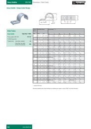
MountingPlease abide by the instructions and observe the correct tightening torques for thefittings or adapters being utilized:Connector thread:½" BSP = 90 Nm¼" BSP = 30 NmPlease observe the highest pressures detailed in the catalogues for hydraulic hosesfrom the Walter <strong>Stauff</strong>enberg GmbH & Co. KG.1.5. Service / RepairFor repairs to or calibration of the measurement instruments, please contact your localSTAUFF sales branch.1.6. Notes on disposalRecycling in accordance with WEEEPurchasing our product gives you the opportunity to return the device to STAUFF at the endof its life cycle.The EU Directive 2002/96 EC (WEEE) regulates the return and recycling of wasteelectrical and electronics equipment.As of 13/<strong>08</strong>/2005 manufacturers of electrical and electronics equipment in the B2B(business-to-business) category are obliged to take back and recycle WEEE free ofcharge sold after this date. After that date, electrical equipment must not bedisposed of through the "normal" waste disposal channels. Electrical equipmentmust be disposed of and recycled separately. All devices that fall under the directivemust feature this logo:Can we be assistance?The Walter <strong>Stauff</strong>enberg Company offers you the option of returning your old device to us atno extra charge. STAUFF will then professionally recycle and dispose of your device inaccordance with the applicable law.What do you have to do?Once your device has reached the end of its service life, simply return it by parcel service (inthe box) to your STAUFF sales branch responsible for customer care – we will then initiatethe necessary recycling and disposal measures. You will incur no costs or suffer anyinconvenience.Any questions?If you have any questions, please contact us or visit our website: www.stauff.com6
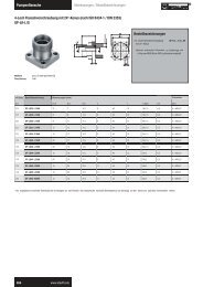
2.0 Device version / Scope of deliveryAccording to your order the Walter <strong>Stauff</strong>enberg Company will supply you one of thefollowing devices:<strong>PPC</strong>-<strong>06</strong> plus<strong>PPC</strong>-<strong>08</strong> plusdevice with 3 sensor inputsdevice with 4 sensor inputsEvery measurement device is supplied with the following components:- Power supply <strong>PPC</strong>-04/12-110V/230V (110/230 V AC)- PC connection cable (USB)- Diagtronics-CD (incl. PC-software, manual and product cataloguesas files)7
3.0 Initial useThe measuring instrument is supplied with rechargeable batteries fitted at the factory.Charge the rechargeable batteries for at least 3 hours before using the first time.The device is then ready for use.3.1. Charging the batteries / Battery status inidcatorIf the battery power is too low, the battery symbol flashes and the measuring turns offautomatically.Battery symbolThe measuring instrument is powered using the external power supply (Power supply<strong>PPC</strong>-04/12-110V/230V) or via the car adapter (Cable <strong>PPC</strong>-04/12-CAB-MOB).The battery can be recharged directly. The charging process begins as soon as the powersupply unit is connected.Please refer to the chapter "Accessories" for more information about the external powersupply unit and the car adapter.8
4.2. Function Keys and Menu KeysFunction KeysON / OFFConfirms functions / valuesSelects functions / valuesSTOP / ESCMenu KeysThese keys are assigned dual functions:Assignment 1. Menu levelAssignment 2. Menu level (black background)= 1 x press= 1 x hold key (2 seconds)ZEROMEMZero point calibrationDifferential value alignmentMemory configurationMain menu (Device Settings)DISPMIN-MAX / ACTUAL or FS displayDisplay configurationRECRecord measurement valuesDeleteDeleting MIN / MAX values10
4.3. Symbols and using the menusIf the sign ">" is displayed at the end of a menu function, press the "OK" key to enteran associated submenu.If the sign ":" is displayed, press the "OK" key to confirm the respective entry.Menu symbol Key Function Example>Call up a submenu /SettingUNIT > .: Confirm AUTO POWER : OFF▲▼ Select --SET-- ▲▼Key assignment and symbols associated with the menu functions are consistentthroughout this device; therefore will be no further explicit explanation given.4.4. What the function keys do within the menusUse the arrow keys to scroll between functions when several functions are available forselection in a window or a menu. The arrow keys move the cursor in the direction in whichthe arrow is pointing.Press the "OK" key each time you wish to select a function or submenu; when makingalterations or adding values you must press "OK" to confirm your action. The "OK" key isused to save all settings.Press the "STOP / ESC" key if you wish to leave a menu or do not wish to save an entry.Key assignment and mode of operation of these three keys is always the same no matter inwhich menu they are used.As the function keys are easy to understand and always function in the samemanner, actuating the function keys has not been included in the examplesequences to ensure that the content of the menus remain central to thedescriptions. It is a pre-condition for replicating the examples that the function keysare used as described above.11
5.0 Connecting the sensors / Display functionsTo avoid electrical interference, please observe the following steps:1 Connect the sensor to the measuring instrument using the connection cable.2 Turn on the measuring instrument.11-30VDC I1 I2 I3I4®PC<strong>PPC</strong>-<strong>06</strong>-plusON/OFFZEROIN1=IN2STOPRECESCOKMEMSETDISPLINERESETMIN/MAXMeasuring instrument with two pressure sensors• Once turned on, all measured values are visible in the display.• Automatic sensor recognition ensures that the measured value is indicated in thecorrect unit.• No further settings to the device are required.• The following message will be displayed if no sensor is connected to the device.12
5.1. Display format (DISP)Press DISP (once)It is possible to change the display format bypressing DISP (once only).Available selection:ACT = Actual valuesMIN = Minimum valuesMAX = Maximum values (pressure spikes)FS = Full scale (upper range value)TEMP = Temperature displayThe TEMP display applies only to the sensor type <strong>PPC</strong>-04/12-PT.13
5.2. Display Configuration (LINE)Press and hold (2 seconds)Line:1: No settings possible; cannot be selected2: Available for selection:Difference (IN1 – IN2)Addition (IN1 + IN2)3: Volume VOL = Q3 x time4: Available for selectionPowerPWR1 = p1 x Q3PWR2 = (p1-p2) x Q314
5.3. Zero Point Calibration (ZERO)If the alignment values are within thepermissible tolerance (2% of FS),the values are set to zero.If the alignment values exceed thepermissible tolerance (2% of FS), thefollowing is displayed: "ZERO OFL"Press ZERO once15
5.4. Deleting MIN / MAX values (RESET)The MAX values measured until now are displayedin the MAX displayDeleting MAX valuesThe updated MAX values are displayed in the MAXdisplay.Example: Loss of pressure in the hydraulic system.5.5. Difference for measuring values►The settings IN1 – IN2 are described in the chapter "Display configuration (LINE)"16
5.6. Differential value alignment (IN1=IN2)Befor running the differential value alignment of two sensors of the same type it is necessaryto run a configuration first.Herefor follow the instructions in chapter 5.2 and calculate the difference of both sensors.Press and hold (2 seconds)Carry out differential value alignment at below operating pressure. Connect twopressure sensors to the same connection (T-adapter). Δp-calibration sets thetolerance of the sensors in relation to one another to zero.This setting remains stored; it is valid only for the respective operating pressure.17
Error messagesThree error messages are possible for IN1 = IN2:1 Alignment value exceed the permissible tolerance:• For sensors with automatic sensor recognition, 5% ofthe upper range value (FS)• For auxiliary sensors, 10% of the upper range value(FS)2 IN1 – IN2 is not configured (DISP-LINE)3 Measured variables are not the same(e.g. IN1=bar, IN2=l/min)18
5.7. Connecting auxiliary sensors (SET AUX: SENSOR)Press and hold (2 seconds)Ensure that the electrical specifications of the auxiliary sensors are compatible withthe measuring instrument / adapter. Please ensure correct PIN assignment andsupply voltage and avoid short-circuits!19
Text input for UNIT / SIGNALTo set the units: Text input up to (max. 15 characters)Numerical input for FROM / TOTo set the measurement range and signal span:3-digit prefixDecimal point3-digit suffix.Measuring instrument with connector adapter and sensors for distance (mm) and force (kN).11...24VDCHandmeter11...24VDCHandmeterADCVDCADCVDC4A48V200mA 10V20mA 3V11-30VDC I1 I2 I34A48V200mA 10V20mA 3VSensorI4®PC<strong>PPC</strong>-<strong>06</strong>-plusSensorON/OFFZEROIN1=IN2STOPRECESCOKMEMSETDISPLINERESETMIN/MAX20
5.8. Error messages / WarningsDisplay Description What action to take?No sensor is connected Turn off the measuring instrumentConnect sensorTurn on the measuring instrument%An auxiliary sensor isconnectedCarry out settings in the menuSET-AUX.SENSORSensor recognitioninterrupted (cable break orinput defect)Send measuring instrument, sensor andconnection to the Walter <strong>Stauff</strong>enbergGmbH & Co. KGMeasurement rangeoverflow. The measuredpressure is outside of themeasurement rangeOverflow ZEROThe zero point offset valueexceeds the toleranceOverflow IN1 = IN2Differential value alignment.The alignment valueexceeds the toleranceDISP LINE IN1 = IN2Wrong settingOverflow IN1 – IN2Differential value alignment.Wrong sensorRelease pressure from the system.Use sensor with wider measurementrange.Check only when no pressure is applied.Test system pressure.Use sensors with wider measurementrange.Configure IN1 – IN2.Measured variables (sensors) must bethe sameIN1 / IN2 = barIN1 / IN2 = l/minIN1 / IN2 = °CMeasured value memory full Download measured values to PC.Delete measured value memory.Do not use in FAST MODERecording time conflict(DURATION)FAST MODE (0,5 ms)Recording time conflict(REC RATE)Setting REC:START-STOP/POINTFAST MODE only for AUTO TRIGGERMANUAL possibleREC settingAUTO TRIGGERMANUALAlter recording time DURATIONSetting MEM-SETREC CONFIGREC RATEAlter recording interval REC RATEPress "OK" to confirm21
6.0 Device settings (SET)Press and hold (2 seconds)22
6.1. Setting the units (SET-UNIT)Available for selection:PRESSURE: bar, mbar, psi, Mpa, kPaTEMPERATURE: °C, °FFLOW:l/min, G/min (US)POWER:kW, HP (US)6.2. Auto power off (SET-AUTO POWER)Available for selection:AUTO POWER:OFF, ON6.3. Setting auxiliary sensors (SET-AUX.SENSOR)►Further information is available in the chapter "Connecting auxiliary sensors".23
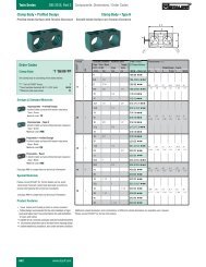
6.4. Displaying defined measurement tasks (SET-PROJECT)Up to five different measurement tasks (PROJECT) can be configured in the PC software.Certain sensors are defined for each input. These definitions can be retrieved in Set-PROJECT.Input 1Wrong sensor connected!Please use measurement range 100.Input 4Correct sensor connected.FS = 600 l/min.It is possible to alter this setting using the PC software.6.5. Setting the contrast (SET-CONTRAST)Available for selection:CONTRAST: 10 ... 100 %24
6.6. Setting the time / date (SET-TIME/DATE)Available for selection:HOUR: 0 ... 23MINUTE: 0 ... 59SECOND: 0 ... 59DAY: 1 ... 31MONTH: 1 ... 12YEAR: 1 ... 996.7. Displaying the device version (SET-VERSION)6.8. Factory setting (USER RESET)Proceed as follows to restore the measuring instrument to its factory-set default settings:1 Turn off the measuring instrument.2 Press and hold down the "MEM-SET" key.3 Press the "ON/OFF" key.4 Press "OK" to confirm the USER RESET25
7.0 Configuring the measured value memory(MEMORY SET)The following settings will be undertaken:• Delete measured value memory• Configure data format of the measured values• Configure recording intervalsMenu Setting /pre-selectionDELETE YESMEMORY: NODATA FORMAT: ACTMIN-MAXREC CONFIG:REC RATE UNIT: msshREC RATE2.000 PTSExampleYESNotesDelete the measured value memoryACT Data format of the measured valuesACT = Save actual valuesMIN-MAX = Save MIN/MAX values2.000 PTS REC RATE = Setting an individualrecording interval2.000 PTS = Dividing the recording timein 2.000 recording intervalsms Pre-selecting time unit(recording interval)REC RATE: Number 20 Setting 20 msWhen defining ACT values, it is possible that important measurement values will notbe saved if the selected recording interval is too great.26
Example:No dynamic MIN-MAX values are saved when the recoding interval is set to 200milliseconds. Therefore, the setting MIN-MAX is recommended for dynamic measurements(pressure spikes).Press and hold (2 seconds)27
7.1. Deleting the measured value memory (MEM-DELETE MEMORY)Press once (briefly)Available for selection:DELETE MEMORY: YES / NOThe measured value memory will be deleted when the "OK" key is pressed to confirmthe action7.2. Setting the data format (MEM-DATA FORMAT)Available selection:DATA FORMAT:ACTMIN/MAXFASTWhen set to FAST, the recording interval for measuring and storing at IN1 is 0.5 ms7.3. Setting the recording format(MEM-REC-CONFIG)REC CONFIGTwo different formats can be set:a. Format 2.000 PTSThe measurement curves are saved with aresolution of 2.000 intervals (points).b. Format REC RATEThe measurement curves are saved at a resolutiondefined interval.Example: 20 ms28
8.0 The REC menu29
9.0 Recording measured values9.1. Settings for recording measured values (REC)The following parameters are displayed in the information bar:REC 1<strong>08</strong>Number of recorded measured values.In this example there are 1<strong>08</strong> measurements saved to memory..Memory allocation17-- Number of measured values that can still be recorded. With the currentsetting / configuration it is possible to save a further 17 measurements.The REC symbol flashes when measured values are being written tomemory31
9.2. The REC NAMES settingDesignations (names) for measurements and channels IN1 / IN2 / IN3 / IN4 are definedthrough the text / numerical input.These settings remain saved in the measuring instrument32
9.3. Memory function START/STOPThe user controls the recording of measured values using START and STOP / ESC keys.The data format FAST (recording interval ACT values in 0.5 ms) cannot be usedwhen the device is in the START / STOP mode.33
The following message is displayed:If the measured value memory is full, the following message is displayed:34
9.4. Memory function POINTMeasurement points representing a given machine sequence (for example: lifting, sinking,operation under load, off-load operation etc.) are saved in a "point-to-point curve". In theexample shown, the channels p1, p2 and Q4 are connected.Pressing the "OK" key saves the measured values Pressing "STOP/ESC" stops therecording and all measured values are saved in the measured value memory.Press to save first data recordFor example. p1, p2 and Q4Press to save second data recordFor example. p1, p2 and Q4Save arbitrary data recordPressingstops the recordingAll data records will be written in the measuredvalue memory35
The data format FAST (recording interval ACT values in 0.5 ms) cannot be usedwhen the device is in the START / STOP mode.The following message is displayed:If the measured value memory is full, the following message is displayed:36
9.5. Memory function AUTO TRIGGERThe function Auto Trigger documents the process of recording measured values triggered bya defined start signal (for example pressure on channel 2 >> 125 bar). In response, asequence of measured values is automatically recorded until the previously setmeasurement time expires.Time-dependent functions (for example making operations or production cycles) aremeasured when recording measured values.The following parameters must be set:MenuTIME UNIT>Setting/Pre-selectionsechrsValueshNotesPre-selected time unit(trigger / pre-trigger)DURATION Number 100 Recording timePRETRIGGER> Number 1 Pre-trigger time(time before the trigger signal)TRIGGER> IN p1 Starting-point measuring channelLEVEL> Number 125 bar Start-point valueTRIG SLOPE> ▲▼ ▲ Ascending or descending edgeAUTO READY> YES, NO YES Recording of measured values isrepeated automatically37
If conflicts arise between the recording time and the set recording interval, thefollowing message is displayed:1. FAST MODEConfiguring a longer recording interval.2. REC RATEConfiguring a longer recording interval.If the measured value memory is full, the following message is displayed:Delete measured value memory or transfer to PC.38
9.6. Memory function MANUALThe manual trigger function documents the process of recording measured values triggeredby a manual start signal initiated by the user. Automatic recording of measured values endsafter predetermined measurement time.For this reason, time-dependent recordings of measured values are started manually.The following parameters must be set:MenuTIME UNIT>Setting/Pre-selectionsechrsExample NoteshPre-selection time unit(trigger / pre-trigger)DURATION Number 100 Recording timePRETRIGGER> Number 1 Pre-trigger time(time before the trigger signal)TRIGGER> IN p1 Starting-point measuringchannel39
If conflicts arise between the recording time and the set recording interval, thefollowing message is displayed:1. FAST MODEConfigure a longer recording interval.2. REC RATEConfigure a longer recording interval.If the measured value memory is full, the following message is displayed:Delete measured value memory or transfer to PC.40
9.7. Recording measured values with default PROJECT settingsIn this setting, measurements are made using a defined sensor configuration. The user usingthe PC software defines this configuration. This avoids false measurements and wrongsettings.The preset parameters are altered in the PC software and transferred to the measuringinstrument.The following parameters can be set:MenuREC NAME>Setting/Pre-selectionNo1 ... 5ExampleNotesLoad Test There are max. 5 predefinedsettings (tests) available forselectionINPUT> PILOT PRS Defined sensors are defined foreach channelWRONGSENSOR!CORRECTSENSOR!USE 150 bar Warns of wrong sensor:A pressure sensor with thecorresponding FS (full scale) mustbe connected to this channelFS 600 l/min Indicates correct sensor.The next channel can beconnected.When all of the sensors are connected, the respective type of recording (START/STOP,POINT, AUTO TRIGGER, MANUAL) is selected and performed automatically. An internalquery of the connected sensors occurs only before choosing the project setting.41
10.0 Setting and operating via PC10.1. Connecting to a PC11-30VDC I1 I2 I3I4®PC<strong>PPC</strong>-<strong>06</strong>-plusON/OFFRECZEROIN1=IN2STOPESCOKMEMSETDISPLINERESETMIN/MAXSteps:1 Connect the measuring instrument to the PC via the USB cable2 Launch PC softwareRun through the PC software. Once the procedure has been confirmed, the measuringinstrument will be initialized and can communicate with the PC.10.2. <strong>Operating</strong> / Configuring via PCAll further steps and settings are described in detail in the PC software:• Online measurement• Reading out the measured value memory• PROJECT definition• Administering and analyzing measurement curves42
11.0 AccessoriesPower supply unit 110/230 VACPower supply <strong>PPC</strong>-04/12-110V/230V(EUR / US / UK / AUS)Car adapter cable 12/24 VDCCable <strong>PPC</strong>-04/12-CAB-MOBConnecting cable3 mCable <strong>PPC</strong>-04/12-CAB35 mCable <strong>PPC</strong>-04/12-EXT5Pressure Sensors-1 ... 15 barSensor <strong>PPC</strong>-04/12-PT-015 /20 ... 60 barSensor <strong>PPC</strong>-04/12-PT-<strong>06</strong>0 /20 ... 150 barSensor <strong>PPC</strong>-04/12-PT-150 /20 ... 400 barSensor <strong>PPC</strong>-04/12-PT-400 /20 ... 600 barSensor <strong>PPC</strong>-04/12-PT-600 /2Pressure peak sensor0 ... 1000 bar Sensor <strong>PPC</strong>-04/12-PT-601 /2Temperature sensorsScrew-in sensor (M10)Sensor <strong>PPC</strong>-04/12-TS–25°C ... 125°C (–13°F …257°F)Hand-held sensorSensor <strong>PPC</strong>-04/12-TSH–25°C ... 125°C (–13°F …257°F)Flow meter1 ... 15 l/min4 ... 60 l/min6 ... 150 l/min10 ... 300 l/min20 ... 600 l/min25 ... 750 l/minGear flow meter0,2 ... 15 l/min0,4 ... 60 l/min0,6 ... 150 l/min1 ... 300 l/minRotational speed sensorFlow meter <strong>PPC</strong>-04/12-SFM-015Flow meter <strong>PPC</strong>-04/12-SFM-<strong>06</strong>0Flow meter <strong>PPC</strong>-04/12-SFM-150Flow meter <strong>PPC</strong>-04/12-SFM-300Flow meter <strong>PPC</strong>-04/12-SFM-600Flow meter <strong>PPC</strong>-04/12-SFM-750Flow meter <strong>PPC</strong>-04/12-SVC-015Flow meter <strong>PPC</strong>-04/12-SVC-<strong>06</strong>0Flow meter <strong>PPC</strong>-04/12-SVC-150Flow meter <strong>PPC</strong>-04/12-SVC-3000 ... 10.000 RPM Sensor <strong>PPC</strong>-04/12-SDS-CABCase (aluminum)Case <strong>PPC</strong>-<strong>06</strong>/12►For further details and other accessories please have a look at our catalog"Diagtronics".43
12.0 Technical DataSensor inputSensor recognition (p/T/Q/n)Connecting auxiliary sensorsPlug-in connection, 5pin Push-pullResolution 12 bit + sign = 4.096 stepsSampling period1 ms0,25 ms FAST MODE (IN1)DisplayLCD 128x64 PixelDisplay size 72x40 mm (2,84 x 1,58 inch)IlluminationHeight of characters 6 mm (0,24 inch)InputMembrane keypadInterface USB 2.0Online speed 20 msACT-MIN-MAXDisplay functionsDifference; addition; power; volumeACT; MIN; MAX; FS; TEMPMeasured value memory Measured value memory 1.000.000 pointsCurve memory: 250.000 pointsData format:ACT; MIN-MAX; FAST (0,25 ms)Memory configuration: Interval (e.g. 5 ms)Points per channel (2.000)Environmental conditions Ambient temperature: 0 … 50°C (32°F... 122°F)Storage temperature: -25°C … 60°C (-13°F... 140°F)Temperature error: 0,02 %/°CRelative humidity:
13.0 Description of the memory functionsConfiguring the measured value memoryDATA FORMAT ACT During the recording interval (for example, 50 ms), thecurrent measurement value (ACT) only will be written tothe measured value memory.MIN-MAX During the recording interval (for example, 50 ms), oneMIN and one MAX value will be written to the measuredvalue memoryREC CONFIG 2.000 PTS The selected recording time is automatically defined intoa fixed number of recording intervals per channel.Example:Recording time 10 min = 600 sDuration of recording interval = 600 s / 2.000 = 300 msREC RATE Definition of an individual recording interval(for example. 5 ms)Based in the settings (DATA FORMAT/REC RATE), themeasuring instrument examines if the selected recordingtime must be extended.Example:Recording time 100 h/ conflictRecording timeFAST MODEACT measured values only are saved at a fixedrecording interval of 0.5 ms via IN1. All other inputs (Inx)are not in function.Selecting the memory function: sensor <strong>PPC</strong>-04/12-PT-XXX /2Recording time 60 sMemory function SettingDATA FORMATSTART / STOPAUTO /MANUALTRIGGERACTMIN-MAXACMIN-MAXSettingREC CONFIGCurve memory(points)Number ofmeasuredvalues / pointsp (bar), T (°C)- 120.000 p (bar) = 15.000T (°C) = 15.0002.000 PTS 250.000 p (bar) = 2.000T (°C) = 60REC RATE (5 ms) 250.000 p (bar) = 12.000T (°C) = 6045
1. Determining the number of the memory functions:ChannelsMeasuredvariableNumber ofmeasuredvaluesExample 14 Sensor <strong>PPC</strong>-04/12-PT °CbarvaluesExample 22 Sensor <strong>PPC</strong>-04/12-PT1 Flow meter <strong>PPC</strong>-04/12-SFM°Cbarl/minNumber of recordingintervals120.000 / measurementvalues = number ofrecording intervals448 120.000 / 8 = 15.0002211 Sensor <strong>PPC</strong>-04/12-SDS-CABRPMvalues16 120.000 / 6 = 20.0002. Determining the duration of the recording interval:Time Channels Number ofmeasuredvaluesExample 160s60.000 ms30s30.000 msExample 260s60.000 ms40s40.000 msDuring of recordinginterval4 Sensor <strong>PPC</strong>-04/12-PT 8 60.000 / 15.000 = 4 ms4 Sensor <strong>PPC</strong>-04/12-PT 8 40.000 / 15.000 = 2 ms2 Sensor <strong>PPC</strong>-04/12-PT1 Flow meter <strong>PPC</strong>-04/12-SFM1 Sensor <strong>PPC</strong>-04/12-SDS-CAB2 Sensor <strong>PPC</strong>-04/12-PT1 Flow meter <strong>PPC</strong>-04/12-SFM1 Sensor <strong>PPC</strong>-04/12-SDS-CAB6 60.000 / 20.000 = 3 ms6 40.000 / 20.000 = 2 ms46
Important information about the START/STOP modeSTART STOP The settings made under REC CONFIG are not relevant in this mode.The recording time is still unknown when the process of recordingmeasured values begins. For this reason, the recording interval isdynamically optimized and appropriately adapted as the measuredvalues are being recorded. The curve memory can store approx. 120.000measured values.When sensors types <strong>PPC</strong>-04/12-PT are connected, the measurementvalues for temperature and pressure are saved at the same recordinginterval.Important information about the AUTO / MANUAL TRIGGER modes:AUTO/MANUALTRIGGERREC CONFIG2.000 PTSREC CONFIGREC RATEThe settings made under REC CONFIG are relevant in this mode.The recording time is known when the process of recording measuredvalues begins.The curve memory can store 250.000 measured values.DURATION / 2000 = duration of the recording interval / channelWhen sensors types <strong>PPC</strong>-04/12-PT are connected, the measuredtemperature values are saved at a recording interval of 1 second.Measured values are recorded at the set interval (REC RATE).When sensors types <strong>PPC</strong>-04/12-PT are connected, the measuredtemperature values are saved at a recording interval of 1 second.47
1. Determining the duration of the recording interval for REC CONFIG 2000 PTS:Time Channels Measuredvalues60s60.000 ms4 Sensor <strong>PPC</strong>-04/12-PT °CbarStored measurement points 8.24030s 4 Sensor <strong>PPC</strong>-04/12-PT °C30.000 msbarStored measurement points 8.12<strong>06</strong>0s 2 Sensor <strong>PPC</strong>-04/12-PT°C60.000 msbar1 Flow meter <strong>PPC</strong>-04/12-SFM l/min1 Sensor <strong>PPC</strong>-04/12-SDS-CAB RPMStored measurement points 8.12040s 2 Sensor <strong>PPC</strong>-04/12-PT°C40.000 msbar1 Flow meter <strong>PPC</strong>-04/12-SFM l/min1 Sensor <strong>PPC</strong>-04/12-SDS-CAB RPMStored measurement points 8.<strong>08</strong>0Number ofmeasurementvalues4x604x2.0004x304x2.0002x602x2.0001x2.0001x2.0002x402x2.0001x2.0001x2.000Duration of therecoding interval60.000 / 2.000 =30 ms30.000 / 2.000 =15 ms60.000 / 2.000 =30 ms40.000 / 2.000 =20 ms2. Determining the number of recording intervals for REC CONFIG/REC RATE 5 ms:Time Channels Measuredvariable60s60.000 ms4 Sensor <strong>PPC</strong>-04/12-PT °CbarStored measurement points 48.24030s30.000 ms4 Sensor <strong>PPC</strong>-04/12-PT °CbarStored measurement points 24.12<strong>06</strong>0s 2 Sensor <strong>PPC</strong>-04/12-PT°C60.000 msbar1 Flow meter <strong>PPC</strong>-04/12-SFM l/min1 Sensor <strong>PPC</strong>-04/12-SDS-CAB RPMStored measurement points 48.12040s 2 Sensor <strong>PPC</strong>-04/12-PT°C40.000 msbar1 Flow meter <strong>PPC</strong>-04/12-SFM l/min1 Sensor <strong>PPC</strong>-04/12-SDS-CAB RPMStored measurement points 32.<strong>08</strong>0Numberof measurementvalues4x604x12.0004x304x6.0002x602x12.0001x12.0001x12.0002x402x8.0001x8.0001x8.000Number ofrecordingintervals60.000 / 5 =12.00030.000 / 5 =6.00<strong>06</strong>0.000 / 5 =12.00040.000 / 5 =8.00048
Walter <strong>Stauff</strong>enberg GmbH & Co. KGPostfach 1745 58777 WerdohlIm Ehrenfeld 4 58791 WerdohlDeutschlandPhone: +49 2392 916-0Fax: +49 2392 2505E-Mail:sales@stauff.comInternet: www.stauff.comSubject to alterationTechnische Änderung vorbehalten /49