
Create successful ePaper yourself
Turn your PDF publications into a flip-book with our unique Google optimized e-Paper software.
REMARQUELa totalité des instructions, garanties et autres documents est sujette à modification à la seule discrétiond’<strong>Horizon</strong> <strong>Hobby</strong>, Inc. Pour obtenir la documentation à jour, rendez-vous sur le site horizonhobby.com et cliquezsur l’onglet de support de ce produit.AVVISOTutte le istruzioni, le garanzie e gli altri documenti pertinenti sono soggetti a cambiamenti a totale discrezionedi <strong>Horizon</strong> <strong>Hobby</strong>, Inc. Per una documentazione aggiornata sul prodotto, visitare il sito www.horizonhobby.come fare clic sulla sezione Support per questo prodotto.Signification de certains termes spécifiquesLes termes suivants sont utilisés dans l’ensemble du manuel pour indiquer différents niveaux de danger lorsde l’utilisation de ce produit:REMARQUE: Procédures qui, si elles ne sont pas suivies correctement, peuvent entraîner des dégâtsmatériels ET éventuellement un faible risque de blessures.ATTENTION: Procédures qui, si elles ne sont pas suivies correctement, peuvent entraîner des dégâtsmatériels ET des blessures graves.AVERTISSEMENT: Procédures qui, si elles ne sont pas suivies correctement, peuvent entraîner desdégâts matériels et des blessures graves OU engendrer une probabilité élevée de blessure superficielle.Significato dei termini particolariIn tutta la documentazione relativa al prodotto sono utilizzati i seguenti termini per indicare vari livelli dipotenziale pericolo durante il funzionamento:AVVISO: Procedure che, se non sono seguite correttamente, possono creare danni materiali E nessunao scarsa possibilità di lesioni.ATTENZIONE: Procedure che, se non sono seguite correttamente, possono creare danni materiali Epossibili gravi lesioni.AVVERTENZA: Procedure che, se non debitamente seguite, espongono alla possibilità di danni allaproprietà fisica o possono omportare un’elevata possibilità di provocare ferite superficiali. Ulteriori precauzioniper la sicurezza e avvertenze.AVERTISSEMENT: Lisez la TOTALITÉ du manuel d’utilisation afin de vous familiariser avec lescaractéristiques du produit avant de le faire fonctionner. Une utilisation incorrecte du produit peutentraîner sa détérioration, ainsi que des risques de dégâts matériels, voire de blessures graves.AVVERTENZA: Leggere TUTTO il manuale di istruzioni e prendere familiarità con le caratteristichedel prodotto, prima di farlo funzionare. Un utilizzo scorretto del prodotto può causare danni al prodottostesso, alle persone o alle cose, provocando gravi lesioni.Ceci est un produit de loisirs sophistiqué. Il doit être manipulé avec prudence et bon sens et requiert desaptitudes de base en mécanique. Toute utilisation irresponsable de ce produit ne respectant pas les principesde sécurité peut provoquer des blessures, entraîner des dégâts matériels et endommager le produit. Ce produitn’est pas destiné à être utilisé par des enfants sans la surveillance directe d’un adulte. N’essayez pas dedémonter le produit, de l’utiliser avec des composants incompatibles ou d’en améliorer les performances sansl’accord d’<strong>Horizon</strong> <strong>Hobby</strong>, Inc. Ce manuel comporte des instructions relatives à la sécurité, au fonctionnementet à l’entretien. Il est capital de lire et de respecter la totalité des instructions et avertissements du manuelavant l’assemblage, le réglage et l’utilisation, ceci afin de manipuler correctement l’appareil et d’éviter toutdégât matériel ou toute blessure grave.Questo è un prodotto di hobbistica sofisticato e NON un giocattolo. È necessario farlo funzionare con cautela eresponsabilità e avere conoscenze basilari di meccanica. Se questo prodotto non è utilizzato in maniera sicura eresponsabile potrebbero verificarsi lesioni o danni al prodotto stesso o ad altre proprietà. Non è un prodotto adattoa essere utilizzato dai bambini senza la diretta supervisione di un adulto. Non tentare di smontare il prodotto, diutilizzare componenti incompatibili o di potenziarlo in alcun modo senza previa approvazione di <strong>Horizon</strong> <strong>Hobby</strong>,Inc. Questo manuale contiene le istruzioni per un funzionamento e una manutenzione sicuri. È fondamentaleleggere e seguire tutte le istruzioni e le avvertenze del manuale prima di montare, configurare o far funzionare ilProdotto, al fine di utilizzarlo correttamente e di evitare danni o lesioni gravi.14 ans et plus. Ceci n’est pas un jouet. Almeno 14 anni. Non è un giocattolo.Utilisation du manuelCe manuel est divisé en sections pour vous aider à comprendre plus facilement l’assemblage. Des cases ()ont été placées à chaque étape. Cela vous permet d’avoir un suivi des étapes déjà effectuées.Come usare il manualeQuesto manuale è diviso in sezioni per rendere più facile la comprensione del montaggio. Vicino ad ogni passosono stati posti dei piccoli quadrati () per aiutare a tenere traccia delle cose fatte e di quelle da fare.3
Safety warnings and precautionsRead and follow all instructions and safety precautionsbefore use. Improper use can result in fire, serious injury anddamage to property.ComponentsUse only with compatible components. Should anycompatibility questions exist, please refer to the productinstructions, component instructions or contact theappropriate <strong>Horizon</strong> <strong>Hobby</strong> office.FlightFly only in open areas to ensure safety. It is recommendedflying be done at AMA (Academy of Model Aeronautics)approved flying sites. Consult local ordinances beforechoosing a flying location.PropellerKeep loose items that can become entangled in the propelleraway from the prop. This includes loose clothing or otherobjects such as pencils and screwdrivers. Keep your handsaway from the propeller as injury can occur.BatteriesAlways follow the manufacturers’ instructions when usingand disposing of any batteries. Mishandling of Li-Po batteriscan result in fire causing serious injury and damage.Small PartsThis kit includes small parts and should not be leftunattended near children as choking and serious injury couldresult.Warnungen und Sicherheit-SicherheitsvorkehrungenBitte lesen und befolgen Sie alle Anweisungen undSichervorkehrungen vor dem Gebrauch. Falscher, nichtsachgemäßer Gebrauch kann Feuer, ernsthafte Verletzungenund Sachbeschädigungen zur Folge haben.KomponentenVerwenden Sie mit dem Produkt nur kompatibleKomponenten. Sollten Fragen zur Kompatibilität auftreten,lesen Sie bitte die Produkt- oder Bedienungsanweisung oderkontaktieren den Service von <strong>Horizon</strong> <strong>Hobby</strong>.FliegenFliegen Sie um Sicherheit garantieren zu können, nur inweiten offenen Gegenden. Wir empfehlen hier den Betrieb aufzugelassenen Modellflugplätzen. Bitte beachten Sie lokaleVorschriften und Gesetze, bevor Sie einen Platz zum Fliegenwählen.PropellerHalten Sie lose Gegenstände die sich im Propellerverfangen können weg vom Propeller. Dieses gilt auch fürKleidung oder andere Objekte wie zum Beispiel Stifte oderSchraubendreher.Halten Sie ihre Hände weg vom Propeller, es besteht akuteVerletzungsgefahr.AkkusFolgen Sie immer den Herstelleranweisungen bei demGebrauch oder Entsorgung von Akkus. Falsche Behandlungvon LiPo Akkus kann zu Feuer mit Körperverletzungen undSachbeschädigung führen.KleinteileAvertissements relatifs à lasécuritéLisez et suivez toutes les instructions relatives à la sécuritéavant utilisation. Une utilisation inappropriée peut entraînerun incendie, de graves blessures et des dégâts matériels.ComposantsUtilisez uniquement des composants compatibles. Si vousavez des questions concernant la compatibilité, référez-vousà ce manuel ou contactez le service technique <strong>Horizon</strong> <strong>Hobby</strong>.Le volVolez uniquement dans des zones dégagées pour unmaximum de sécurité. Il est recommandé d’utiliser les pistesdes clubs d’aéromodélisme. Consultez votre mairie pourconnaître les sites autorisés.L’héliceGardez éloignés tous les éléments qui pourraient êtreattrapés par l’hélice. Cela inclut les vêtements larges ou lesobjets comme des outils par exemple. Gardez toujours vosmains à distance pour éviter tout cas de de blessures.Les batteriesSuivez toujours les instructions du fabricant de vosbatteries. Une mauvaise manipulation d’une batterieLi-Po peut entraîner un incendie causant de graves dégâtsmatériels et des blessures corporelles.Petites piècesCe kit contient des petites pièces qui ne doivent pasêtre laissées à la portée des enfants, ces pièces sontdangereuses pour eux et peuvent entraîner de gravesblessures.AVVERTIMENTI E PRECAUZIONI PER LASICUREZZAPrima dell’uso leggere attentamente tutte le istruzioni e leprecauzioni per la sicurezza. In caso contrario si potrebberoprocurare incendi, danni o ferite.ComponentiUsare solo componenti compatibili. Se ci fossero dubbiriguardo alla compatibilità, è opportuno far riferimentoalle istruzioni relative al prodotto o ai componenti oppurerivolgersi al reparto <strong>Horizon</strong> <strong>Hobby</strong> di competenza.VoloPer sicurezza volare solo in aree molto ampie. Meglio se siva su campi volo autorizzati per modellismo. Consultare leordinanze locali prima di scegliere una ubicazione.ElicaTenere gli oggetti liberi (vestiti, penne, cacciaviti, ecc.)lontano dall’elica, prima che vi restino impigliati. Bisognafare attenzione anche con le mani perché c’è il rischio diferirsi anche gravemente.BatterieQuando si maneggiano o si utilizzano le batterie, bisognaattenersi alle istruzioni del costruttore; il rischio è diprocurare incendi, specialmente con le batterie LiPo, condanni e ferite serie.Piccole partiQuesto kit comprende delle parti di piccole dimensioni e nonlo si può lasciare incustodito se c’è la presenza di bambiniche li possono inghiottire e rimanere soffocati o intossicati.Dieser Baukasten beinhaltet Kleinteile und darf nichtunbeobachtet in der Nähe von Kindern gelassen werden,da die Teile verschluckt werden könnten mit ernsthaftenVerletzung zur Folge.4
Safe operating recommendations• Inspect your model before every flight to ensure it isairworthy.• Be aware of any other radio frequency user who maypresent an interference problem.• Always be courteous and respectful of other users in yourselected flight area.• Choose an area clear of obstacles and large enough tosafely accomodate your flying activity.• Make sure this area is clear of friends and spectatorsprior to launching your aircraft.• Be aware of other activities in the vicinity of your flightpath that could cause potential conflict.• Carefully plan your flight path prior to launch.Empfehlungen zum sicherenBetrieb• Überprüfen Sie zur Flugtauglichkeit ihr Modell vor jedemFlug.• Beachten Sie andere Piloten deren Sendefrequenzen ihreFrequenz stören könnte.• Begegnen Sie anderen Piloten in ihrem Fluggebiet immerhöflich und respektvoll.• Wählen Sie ein Fluggebiet, dass frei von Hindernissen undgroß genug ist.• Stellen Sie vor dem Start sicher, dass die Fläche frei vonFreunden und Zuschauern ist.• Beobachten Sie den Luftraum und andere Flugzeuge/Objekte die ihren Flugweg kreuzen und zu einem Konfliktführen könnten.Consignes de sécurité concernantl’utilisation• Inspectez votre modèle avant chaque vol.• Surveillez les fréquences utilisées à proximité.• Soyez toujours courtois et respectueux des autresutilisateurs de la zone de vol.• Choisissez une zone dégagée de tout obstacle etsuffisamment grande pour voler en toutes sécurité.• Contrôlez que la zone est libre de spectateurs avant delancer votre modèle.• Soyez conscient des autres activités aux alentours devotre vol, risque de conflit potentiel.• Planifiez votre vol avant de le commencer.Raccomandazioni per operare insicurezza• Controllare attentamente il modello prima di ogni volo peraccertarsi che sia idoneo.• Essere consapevoli che un altro utente della frequenza inuso, potrebbe procurare delle interferenze.• Essere sempre cortesi e rispettosi nei confronti degli altriutilizzatori dell’area in cui ci si trova.• Scegliere un’area libera da ostacoli e abbastanza ampiada permettere lo svolgimento del volo in sicurezza.• Prima del volo verificare che l’area sia libera da amici espettatori.• Stare attenti alle altre attività che si svolgono invicinanza della vostra traiettoria di volo, per evitarepossibili conflitti.• Abide by any and all established AMA National ModelAircraft Safety Code.• Planen Sie sorgfältig ihren Flugweg vor dem Start.• Pianificare attentamente il volo prima di lanciare ilmodello.• Rispettare sempre scrupolosamente le regole stabilitedall’associazione locale.Fasteners/Verbindungselemente/Attaches/Elementi di fissaggioFlat WasherUnterlegscheibeRondelle plateRondella piattaLock NutStopmutterEcrou auto-freinéDado di bloccaggioSetscrewMadenschraubeVis sans têteSet di vitiHex NutSechskantmutterEcrou hexagonalDado esagonaleSelf-Tapping ScrewSelbstschneidene SchraubeVis auto-taraudeuseVite autofilettanteNylon ClevisNylon GabelkopfChape nylonCambra di nylonSocket Head Cap ScrewInbusschraubeVis BTRVite a brugolaButton Head Cap ScrewHalbrundschraubeVis à tête bombéeVite a brugola a testa bombataSelf-Tapping Washer-Head ScrewSchraube mit UnterlegscheibenkopfVis auto-taraudeuse épauléeVite autofilettante flangiataBlind nutEinschlagmutterÉcrou borgneDado ciecoQuick ConnectorSchnellverbinderConnecteur rapideConnettore rapido5
Specifications/Spezifikationen/Spécifications/SpecificheLarge Parts Layout/Bauteile (ohne Kleinteile)/Grandes Pièces/Schema dei componenti grandi106 in (269cm)1630 sq in (<strong>150</strong> dm 2 ) Total/Totale51131668.0 in (173 cm)16.5–<strong>18</strong>.5 lb (7.5–8.4 kg)2-Stroke Gas/2-Takt Benziner/2 temps Essence/2-Tempi Gas20–26cc4-Stroke Gas/4-Takt Benziner/4 temps Essence/4-Tempi Gas30cc2-Stroke Glow/2-Takt Glühzünder/2 temps méthanol/2-Tempi Glow1.20–1.604-Stroke Glow/4-Takt Glühzünder/4 temps méthanol/4-Tempi Glow1.20–1.80Electric Power/Elektro Antrieb/Moteur électrique (EP)/Motore elettricoPower 1105-channel (or greater) with 8 servos5- Kanal (oder größer) mit 8 Servos5 voies (ou plus) avec 8 servos5 canali (o più) con 8 serviSpinner/Spinner/Cône/Ogiva dell’elica2 1 / 2-inch (64 mm) (included/inklusive/inclus/inclusa)11374814917126<strong>18</strong>151026
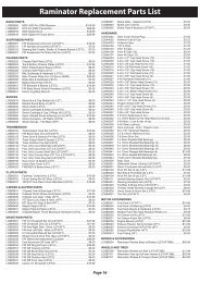
Replacement parts/Ersatzteile/Pièces de rechange/RicambiE english deutsch français italiano1. HAN454001 Fuselage Rumpf Fuselage Fusoliera2. HAN454002 Left Wing with Aileron and Flap Tragfläche Links mit Querruder und Klappe Aile gauche avec aileron et volet Semiala sinistra con alettone e flap3. HAN454003 Right Wing with Aileron and Flap Tragfläche Rechts mit Querruder und Klappe Aile droite avec aileron et volet Semiala destra con alettone e flap4. HAN454004 Stabilizer and Elevator Set Höhenruderset Stabilisateur et Gouverne de profondeur Set stabilizzatore ed elevatore5. HAN454005 Rudder Seitenleitwerk Dérive Timone6. HAN454006 Cowl Motorhaube Capot Capottina motore7. HAN454007 Anodized Aluminum Wing Tube Aluminium Flächenverbinder Clé d’aile en aluminium anodisé Tubo ala in alluminio anodizzato8. HAN454008 Landing Gear without Wheels Fahrwerk ohne Räder Train d’atterrissage sans roues Carrello senza ruote9. HAN454009 Main Wheel Set (Pair) Fahrwerksräder Set Paire de roues principales Set ruota principale10. HAN454010 Wing Struts Set (Left and Right) Tragflächenstreben (Links und Rechts) Jeu de haubans d’aile (Gauche et Droite) Set montanti ala (destro e sinistro)11. HAN454011 Window Set Fenster Set Jeu de vitrage Set finestrature12. HAN454013 Painted Aluminum Spinner Aluminiumspinner lackiert Cône en aluminium peint Ogiva in alluminio verniciata13. HAN454014 Tail Wheel with Wheel Spornradset Roulette de queue avec roue Carrello coda con ruota14. HAN454015 Landing Gear Airfoil Strut Covers (pair) Fahrwerksverkleidungen (1 Paar) Carénage d’amortisseur de train d’atterrissage (paire) Carenature gambe carrello (paio)15. HAN454016 Seats (2), Dash panel Sitze (2), Instrumententafel Sièges (2), Tableau de bord Sedili (2), Cruscotto16. HAN454020 Tail Wire Bracing Leitwerksverspannung Renfort de câble de queue Controventature coda17. HAN454021 Windshield Screen Windschutzscheibe Écran de pare-brise Schermo parabrezza<strong>18</strong>. HAN4566 Full Body Poseable Pilot, 25% Pilotenfigur 25% Pilote, 25% Figura pilotaSmall Parts (Not Shown)/Kleinteile nicht abgebildet/Petites Pièce (Non Illustrées)/PICCOLE <strong>PA</strong>RTI (NON ILLUSTRATE)HAN454012 Pushrods Schubstangen Tringleries Barrette comandiHAN454017 Hardware Package Kleinteile Packet Sachet de visserie Pacchetto raccordi metalliciHAN4540<strong>18</strong> Optional EP Motor Mount and Battery Tray Optionaler Elektro- Motorträger und Akkuhalter Support moteur EP et compartiment batterie optionnels Supporto motore e batteria opzionali7
Assembly Symbol Guide/Montage Symbole /Guide des Symboles pour assemblage /Guida ai simboli di assemblaggioApply threadlockEnsure free rotationUse medium CAUse a pencilSchraubensicherungslack verwendenUtilisez du frein filetApplicare fuido threadlockRotation sicherstellenPermettez une rotation libreAssicurarsi rotazione liberaMittelflüssigenSekundenkleber verwendenUtilisez de la collecyanoacrylate moyenneVerwenden Sie einen BleistiftUtilisez un crayon à papierUsare una matitaUsare colla ciano acrilica mediaLRLRAssemble right and leftLinks und rechts montierenAssemblez à droite et à gaucheAssemblare destra e sinistraPush tightlyFest drückenSerrez fortementSpingere forteUse thin CADünnflüssigenSekundenkleber verwendenUtilisez de la collecyanoacrylate fineUse a felt-tipped penVerwenden Sie einen FaserstiftUtilisez un feutre fin effaçableUsare un pennarelloUsare colla ciano acrilica finex2Repeat multiple times(as indicated)Vorgang wiederholen(wie angezeigt)Répétez comme indiquéRipetere piu’ volte(come indicato)OILApply oilÖl verwendenAppliquez lubricantApplicare olio15Use 15-minute epoxyVerwenden Sie 15 Minuten EpoxyUtilisez de l’époxy 15 minutesUsare una resina epossidica conindurimento di 15 minutiFully tightenVollständig festziehen/festschraubenSerrez complètementStringere al massimoEnsure proper orientationAusrichtung/Richtung sicherstellenVérifiez la bonne orientationAssicurarsi dell’appropriatoorientamentoAttach temporarilyVorübergehend anbringenAttachez temporairementAttaccare temporaneamente30Use 30-minute epoxyVerwenden Sie 30 Minuten EpoxyUtilisez de l’époxy 30 minutesUsare una resina epossidica conindurimento di 30 minutiUse hobby knife with#11 bladeVerwenden Sie ein <strong>Hobby</strong>messer mit #11 KlingeUtilisez un Couteau: Lame numéro 11Usare taglierino per hobbistica conlama numero 1<strong>18</strong>
Required Radio Equipment/erforderliche RC Ausrüstung/Equipement radio requis/Apparecchiature radioE english deutsch français italianoSPMAR9020 AR9020 9-Channel DSMX ® X-Plus Receiver Spektrum AR9200 DSMX 9 Kanal X Plus Empfänger Récepteur AR9020 9-voies DSMX X-Plus AR9020 9-Canali DSMX X-Plus RicevitoreJR<strong>PA</strong>004 JR ® Chargeswitch Ladestecker Interrupteur de charge JR JR Interruttore per caricaJR<strong>PA</strong>212 Large Servo Horns with Screws Große Servohörner mit Schrauben Bras de servo de grande taille avec vis Squadrette grandi per servo c/vitiSPMB2700NM 2700mAh 6V NiMH Receiver Battery 2700mAh 6Volt NiMh Empfänger Akku Batterie récepteur NiMH 6 V 2700 mAh 2700mAh 6V MiMH Batteria per ricevitoreJRPS821 (8) DS821 Digital Sport Servo DS821 Digital Sport Servo Servo Digital Sport DS821 DS821 Servo digitale sport*SPMA3004 (4) <strong>18</strong>-inch Heavy-Duty Servo Extension Servokabelverlängerung 457 mm (<strong>18</strong> inch) Rallonge de servo, 457 mm Estensione servo <strong>18</strong> polliciSPMA3005 (2) 24-inch Heavy-Duty Servo Extension Servokabelverlängerung 609 mm (24 inch) Rallonge de servo, 609 mm Estensione servo 24 polliciGasoline Engine/MOTEUR A ESSENCE/MOTORE A BENZINAZENE26A Zenoah G-26, 1.55 cu in Zenoah G-26, 1.55 cc in Zenoah G-26, 1.55 cu in (22,122 cm 3 ) Zenoah G-26, 1.55 cu inEVO16060 Evolution ® 16 x 6 Propeller Evolution 16 x 6 Propeller Hélice 16 x 6 Evolution Evolution 16 x 6 ElicaHAN143 Pro Fuel Filter Spritfilter: Gas, Glow Filtre carburant Pro Filtro carburante ProHAN116 Fuel Filler with “T” and Overflow Fittings Tanknippel mit T-Stück u. Überlauf Fitting Remplissage carburant avec raccords en Riempitore carburante con “T” e raccordi troppo pieno« T » et de débordementZEN20000 Zenoah Kill Switch Zenoah Killschalter Coupe-circuit Zenoah Zenoah interruttore spegnimentoDUB799 Tygon Tubing, 3 ft. Krafttstoffschlauch 1 Meter Durite Tygon, 3 ft (+/- 90 cm) Tubetti Tygon, 3 ft (1m)4-Stroke/4-Takt/4 temps/4-TempiSAIE<strong>18</strong>2TD Saito <strong>18</strong>2 Twin, Dual-Plug Saito <strong>18</strong>2 Twin Zylinder Saito <strong>18</strong>2 Twin, double bougie Saito <strong>18</strong>2 Twin, Dual-PlugAPC16080 16 x 8 Propeller 16 x 8 Propeller Hélice 16 x 8 16 x 8 ElicaDUB222 (2) Silicone Fuel Tubing, 2 ft Silikonkraftstoffschlauch 1Meter Durite carburant silicone, 2 ft (+/- 60 cm) Tubetto silicone carburante, 2 ftHAN116 Fuel Filler Tanknippel mit T-Stück u. Überlauf Fitting Remplissage carburant Riempitore carburanteHAN143 Fuel Filter Spritfilter: Gas, Glow Filtre carburant Filtro carburanteTRU0828A Spinner Adapter Spinner Adapter Adaptateur de cône Adattatore ogivaSAI<strong>18</strong>2TD1112 Flexible Exhaust, Right flexibler Auslass rechts Échappement flexible, Droite Flessibile per scarico, destroSAI<strong>18</strong>2TD1111 Flexible Exhaust, Left flexibler Auslass links Échappement flexible, Gauche Flessibile per scarico, sinistroSAI300T99A Muffler Bracket Dämpferhalter Bride de silencieux Supporto silenziatoreMCD474 On-Board Glow Bordglühsystem Bougie embarquée Accensione a bordo9
Electric Power/Elektroantrieb/MOTEUR ELECTRIQUE (EP)/MOTORE ELETTRICOE english deutsch français italianoEFLM4110A Power 110 Outrunner Brushless, 295Kv Power 110 Außenläufer Brushless, 295Kv Power 110 Outrunner Brushless, 295Kv Power 110 Cassa rotante Brushless, 295KvCSE010006700 Phoenix ICE 75 Brushless ESC Phoenix ICE 75 Brushless ESC / Regler CEV (ESC) Brushless Phoenix ICE 75 Phoenix ICE 75 Brushless ESC (regolatore)APC19010E APC 19 x 10 Electric Propeller Elektro Propeller, 19x10E Hélice électrique, 19X10E Elica elettrica sottile, 19x10EEFLB50004S30 (2) 4S 14.8V 5000mAh Li-Po Battery 5000mAh 4S 14.8V 30C Li-Po Batterie Li-Po 14.8V 4S 5000mA 30C 5000mAh 4S 14.8V 30C Li-PoEFLAEC501 (2) EC5 Device Connector, Male E-flite EC5 Steckverbindung Stecker Connecteur d’équipement EC5, mâle EC5 Device Connettore, maschioEFLAEC506 EC5 Extension Lead with 6-inch Wire EC5 Verlängerung mit 6 inch Kabel; 10Awg Câble d’extension EC5 avec câble 6-inch (152 mm) EC5 Prolunga con 152 mm di filoEFLAEC508 EC5 Battery Series Harness, 10Awg E-flite EC5 Akkukabel seriell; 10Awg Câble pour batterie série EC5, 10Awg EC5 Serie collegamenti batteria Ø 2,5 mmSPMA3003 12-inch Heavy-Duty Servo Extension Servokabelverlängerung 304 mm (12 inch) Rallonge de servo, 304 mm Estensione servo 12 polliciDUB582 10-32 x 1 1 / 4-inch SHCS Inbusschrauben 10-32 x 1 1 / 4-inch 10-32 x 1 1 / 4-inch SHCS 10-32 x 1 1 / 4-inch SHCSOptional Lighting/Optionale Beleuchtung/ECLAIRAGE OPTIONNEL/LUCI OPZIONALIEFLA600 Controller: Universal Lighting Kit Controller: Universal Beleuchtungs Kit Contrôleur: Kit d’éclairage universel Controller: Kit illuminazione universaleEFLA601 Solid Red LED Rote LED leuchtend DEL rouge fixe LED rosso fissoEFLA602 (2) Solid Clear LED Klare LED leuchtend DEL blanche fixe LED bianco fissoEFLA604 Solid Green LED Grüne LED leuchtend Universal Beleuchtungs Kit DEL verte fixe LED verde fissoEFLA617 (2) 6-inch Lighting Y-Harness Y-Kabel; HD 6 Universal Beleuchtungs Kit Câble Y d’éclairage (152 mm) Cavi a Y per luci da 152 mm*EFLA6<strong>18</strong> (2) <strong>18</strong>-inch Lighting Extension Verlängerung <strong>18</strong> inch: Universal Beleuchtungs Kit Extension d’éclairage (457 mm) Prolunghe per luci da 457 mmEFLA620 36-inch Lighting Extension Verlängerung 36 inch: Universal Beleuchtungs Kit Extension d’éclairage (914 mm) Prolunghe per luci da 914 mmSPMA3004 <strong>18</strong>-inch Servo Extension Servokabelverlängerung <strong>18</strong> inch (457 mm) Extension de servo (457 mm) Prolunga servo da 457 mmOptional Interior Items/Optionale Inneneinrichtung/Eléments optionnels d’intérieur du cockpit/Interni OpzionaliHAN454019 Optional Interior Cockpit Detail Kit Cockpit Interieur Kit Kit de détail d’intérieur de cockpit optionnel Kit opzionale dettagli cruscottoEFLA619 (2) 24-inch Lighting Extension Verlängerung 24: Universal Beleuchtungs Kit Extension d’éclairage (609 mm) Prolunghe per luci da 609 mmSPMA3005 (4) 24-inch Heavy-Duty Servo Extension Servokabelverlängerung 609 mm (24 inch) Rallonge de servo, 609 mm Estensione servo 24 pollici* Substitute 24-inch (609 mm) extensions listed for the <strong>18</strong>-inch (457 mm) extensions listed in the “Required Equipment” and “Optional Lighting” parts listings when installing the Optional Interior.* Ersetzen Sie die <strong>18</strong> inch (457 mm) Verlängerung mit der 24inch 609 mm Verlängerung wenn Sie die optionale Inneneinrichtung einbauen.* Substituer des extensions (609 mm) aux extensions (457 mm) mentionnées dans les listes des pièces « Équipement Requis » et « Éclairage Optionnel » en cas d’installation de l’intérieur en option.* Quando si installano gli interni opzionali, sostituire le prolunghe da 609 mm con quelle da 457 mm elencate negli equipaggiamenti richiesti e nelle luci opzionali.10
Required Adhesives/erforderliche Klebstoffe/Types de Colles Requis/Adesivi necessariE english deutsch français italiano<strong>PA</strong>APT56 Canopy Glue Kabinenhaubenkleber Colle à verrière Colla per il tettuccio<strong>PA</strong>APT03 Medium CA Sekundenkleber mittel Colle cyano moyenne Medio CA<strong>PA</strong>APT09 Thin CA Sekundenkleber dünnflüssig Colle cyano fine Sottile CA<strong>PA</strong>APT42 Threadlock Schraubensicherungslack Frein-filet Frenafiletti<strong>PA</strong>APT35 15-minute Epoxy 15 Minuten Epoxy Époxy 15 minutes Colla epoxy 15 minuti<strong>PA</strong>APT39 30-minute Epoxy 30 Minuten Epoxy Époxy 30 minutes Colla epoxy 30 minutiOptionaL Items/Optionale Teile/Eléments Optionnels/Articoli OpzionaliEFLA110 Power Meter E-flite Lastmessgerät Wattmètre Misuratore di potenzaEFLC3020 Celectra 200W DC Charger E-flite 200W DC Multi-Akku Ladegerät Chargeur CC 200W Celectra Celectra 200W DC Caricabatterie11
Required Tools/Benötigtes Werkzeug/Outils requis/Attrezzi Necessari12English deutsch français italianoAdjustable wrench Adjustable wrench Clé ajustable Chiave regolabileClear tape klares Klebeband Ruban adhésif transparent Nastro trasparenteCovering iron Folienbügeleisen Fer à entoiler Ferro per ricoperturaCrimping tool Crimpzange Pince à sertir Pinza crimpatriceDenatured alcohol Spiritus Alcool dénaturé Alcol denaturatoDental floss Zahnseide Fil dentaire Filo interdentaleDish washing detergent Spülmittel Liquide vaisselle Detersivo per i piattiDrill Bohrer Mini-perceuse TrapanoDrill bit: 1/16-inch, 5/64-inch, 1/8-inch, 5/32-inch, 7/32-inch Bohrer: 1,5 mm, 2 mm, 3 mm, 4 mm, 5,5 mm Forêt : 1,5 mm, 2 mm, 3 mm, 4 mm, 5,5 mm Punte per trapano: 1,5 mm, 2 mm, 3 mm, 4 mm, 5,5 mmEpoxy brushes Pinsel Pinceau Epoxy Spazzole epoxyFelt-tipped pen Faserstift Feutre fin effaçable PennarelloFlat blade screwdriver: small Schraubendreher klein Petit tournevis à tête plate Cacciavite piccolo a lama piattaFlat file Flachfeile Lime plate Lima piattaHemostat Klemme Pince Hemostat PinzettaHex wrench: 1.5mm, 2.5mm, 1/16-inch, 5/64-inch, Inbusschlüssel: 1,5 mm, 2,5 mm, 1/16-inch, 5/64-inch, Tournevis hexagonal: 1,5 mm, 2,5 mm, 1/16-inch, 5/64-inch, Chiave esag.: 1,5 mm, 2,5 mm, 1/16-inch, 5/64-inch,3/32-inch, 1/8-inch, 9/64-inch, 5/32-inch 3/32-inch, 1/8-inch, 9/64-inch, 5/32-inch 3/32-inch, 1/8-inch, 9/64-inch, 5/32-inch 3/32-inch, 1/8-inch, 9/64-inch, 5/32-inch<strong>Hobby</strong> knife: #11 blade <strong>Hobby</strong>messer mit # 11 Klinge Couteau : Lame numéro 11 Taglierino: #11 lamaLight machine oil Nähmaschinenöl Lubrifiant Olio leggeroLow-tack tape Klebeband m. geringer Klebekraft Adhésif de masquage Nastro a bassa aderenzaMedium grit sandpaper Schleifpapier mittel Papier à poncer grain moyen Carta vetrata mediaMixing cups and sticks Mischbecher und Rührstäbchen Récipients pour mélanger et bâtons Contenitori e stick per mixer collaNeedle nose pliers Spitzzange Pince fine Pinze a becco strettoNut driver: 1/4-inch, 7 mm Steckschlüssel: 1/4-inch, 7 mm Clés pour écrous : 1/4-inch, 7 mm Giradadi: 1/4-inch, 7 mmOpen-end wrench: 1/2-inch, 14 mm Maulschlüssel: 1/2-inch, 14 mm Clé plate ouverte : 1/2-inch, 14 mm Chiave aperta: 1/2-inch, 14 mmPaper towels Papiertücher Papier absorbant Asciugamani di cartaPencil Stift Crayon à papier MatitaPhillips screwdriver: #1, #2 Phillips Schraubendreher: #1,#2 Tournevis cruciforme: #1, #2 Cacciavite a croce: #1, #2Pin vise Handbohrer Porte forets Morsa stretta
Razor saw Säge Lame de rasoir Sega RazorReamer Reibahle Alésoir AlesatoreRuler Lineal Réglet RighelloScissors Schere Ciseaux ForbiciSide cutters Seitenschneider Pince coupante Lama lateraleWire Stripper Abisolierzange Pince à dénuder SpellafiliBefore Starting AssemblyVor dem ZusammenbauAvant de commencer l’assemblagePrima di iniziare il montaggio• Remove parts from bag.• Entnehmen Sie zur Überprüfung jedes Teil der Verpackung.• Retirez toutes les pièces des sachets pour les inspecter.• Togliere tutti i pezzi dalla scatola.• Inspect fuselage, wing panels, rudder and stabilizer fordamage.• Überprüfen Sie den Rumpf, Tragflächen, Seiten- undHöhenruder auf Beschädigung.• Inspectez soigneusement le fuselage, les ailes et lesempennages.• Verificare che la fusoliera, l’ala e i piani di coda non sianodanneggiati.• If you find damaged or missing parts, contact your placeof purchase.If you find any wrinkles in the covering, use a heat gun(HAN100) and covering glove (HAN<strong>150</strong>) or covering iron(HAN101) with a sealing iron sock (HAN141) to remove them.Use caution while working around areas where the colorsoverlap to prevent separating the colors.• Charge transmitter and receiver batteries.• Center trims and sticks on your transmitter.• For a computer radio, create a model memory for thisparticular model.• Bind your transmitter and receiver, using your radiosystem’s instructions.Attention: Rebind the radio system once all controlthrows are set. This will keep the servos from moving to theirendpoints until the transmitter and receiver connect. It willalso guarantee the servo reversal settings are saved in theradio system.• Sollten Sie beschädigte oder fehlende Teile feststellen,kontaktieren Sie bitte den Verkäufer.Zum Entfernen von Falten in der Bespannung verwendenSie den Heißluftfön (HAN100) und Bespannhandschuh(HAN<strong>150</strong>) oder das Folienbügeleisen (HAN141). Bitte achtenSie bei überlappenden Farben, dass Sie diese sich bei demBearbeitung nicht trennen.• Laden des Senders und Empfängers.• Zentrieren der Trimmungen und Sticks auf dem Sender.• Sollten Sie einen Computersender verwenden, resetten Sieeinen Speicherplatz und benennen ihn nach dem Modell.• Sender und Empfänger jetzt nach den Bindeanweisungdes Herstellers zu binden.WICHTIG: Wir empfehlen dringend nachdem alleEinstellungen vorgenommen worden sind, das Modellneu zu binden. Dieses verhindert, dass die Servos in dieEndanschläge laufen bevor sich Sender und Empfängerverbunden haben. Es garantiert auch, dass dieServoreverseeinstellungen in der RC Anlage gesichert sind.• Si un élément est endommagé , contactez votre revendeur.Si l’entoilage présente quelques plis, vous pouvez les lisseren utilisant le pistolet à air chaud (HAN100) et le gant(HAN<strong>150</strong>) ou le fer à entoiler (HAN101) avec la chaussettede protection (HAN141). Agissez soigneusement dans leszone ou plusieurs couleurs d’entoilage sont superposées afind’éviter de les séparer.• ll est recommandé de préparer tous les éléments dusystème de la radio.• Cela inclus, la charge des batteries comme la mise auneutre des trims est des manches de votre émetteur.• Si vous utilisez une radio programmable, sélectionnez unemémoire libre afin d’y enregistrer les paramètres de cemodèle.• Nous vous recommandons d’affecter maintenant lerécepteur à l’émetteur en suivant les instructions fourniesavec votre radio.ATTENTION: Il est hautement recommandé deré-affecter le système une fois que les courses serontréglées. Cela empêchera les servos d’aller en butée lors dela connexion du système. Cela garantit également que ladirection des servos est enregistrée dans l’émetteur.• Se si trovano parti danneggiate, contattare il negozio dacui è stato acquistato.Se si trovano delle rughe nella ricopertura, si possonotogliere usando una pistola ad aria calda (HAN100) e guantoper ricopertura (HAN<strong>150</strong>), oppure un ferro per ricopertura(HAN101) con la sua calza di protezione (HAN141). Usarecautela quando si lavora in aree del rivestimento dove cisono dei colori sovrapposti, per evitare la loro separazione.• Caricare il trasmettitore e la batteria di volo.• Centrare stick e trim sul trasmettitore.• Con una radio computerizzata creare una nuova memoriaper questo modello.• Facendo riferimento alle istruzioni del radiocomando,connettere (bind) trasmettitore e ricevitore.ATTENZIONE: Ripetere la procedura di connessioneuna volta regolate le corse, per evitare che i servi vadano afine corsa. Garantirà anche che le impostazioni di inversionedel servo vengano salvate nel sistema radio.13
LRLRLRLR5678LR15LRLRLRApply epoxy to the outside of the hinge using a toothpick.Install the hinges and allow the epoxy to fully cure beforeproceeding.Geben Sie mit einem Zahnstocher Expoxy auf die Aussenseitedes Scharnieres. Setzen Sie das Scharnier ein und lassenden Klebstoff vollständig trocknen bevor Sie fortfahren.Appliquer de l’époxy à l’extérieur de la charnière en utilisantun cure-dent. Installer les charnières et laisser le temps àl’époxy de durcir complètement avant de poursuivre.Mettere della colla epoxy sull’esterno della cerniera con unostuzzicadenti. Inserire le cerniere e aspettare che la collaindurisca.Position the hinges in the flap. Use care not to damage thescale covering on the flap. Do not use glue on the flaphinges.Positionieren Sie Scharniere in den Klappen. Bitte sein Sievorsichtig die Scale Bespannung auf den Klappen nicht zubeschädigen. Kleben Sie die Scharniere jetzt noch nichtein.Positionner les charnières dans le volet. Faire bien attentionà ne pas endommager les détails que comporte le volet. Nepas utiliser de colle sur les charnières des volets.Posizionare le cerniere nei flap, facendo attenzione a nonrovinare il rivestimento. Non usare colla sulle cerniere deiflap.Trim the opening for the flap hinges, removing any excesscovering from the holes.Bearbeiten Sie die Öffnung für die Klappenscharniere undentfernen überschüssige Bespannung von den Löchern.Découper l’ouverture pour les charnières de volets etdébarrasser les trous de tout excès de revêtement.Aprire le aperture per le cerniere dei flaps, togliendol’eccesso di rivestimento dai fori.Fit the flap to the wing. Align the flap with the wing, then uselow-tack tape to hold the flap in position. Do not use glueon the flap hinges.Passen Sie die Klappe an der Fläche an und richten dieseaus. Fixieren Sie die Klappe mit Klebeband mit geringerKlebekraft. Verwenden Sie keinen Klebstoff auf denScharnieren.Monter le volet sur l’aile. Aligner le volet avec l’aile, etutiliser ensuite du ruban adhésif de masquage pourmaintenir le volet en position. Ne pas utiliser de colle surles charnières des volets.Inserire i flap sull’ala, allineandoli e tenendoli fermi con delnastro a bassa aderenza. Non usare colla sulle cernieredei flap.15
LRLRLR9101112LRLRLREnsure the flap control horn aligns with the hole in thetrailing edge of the right and left wing for the flap linkage.Stellen Sie sicher, dass das Klappenruderhorn mit dem Lochin der Tragflächekante übereinstimmt.Assurez-vous que le bras de commande de volet s’aligneavec le trou pour la biellette de volet dans le bord de fuitedes ailes droite et gauche.Controllare che la squadretta dei flap sia allineata con ilforo sul bordo di uscita della semiala destra e sinistra per ilpassaggio del collegamento.Position the aileron on the wing. Use low-tack tape to holdthe aileron in aligning at the wing tip.Richten Sie die Querruder zur Tragflächenspitze aus. FixierenSie die Ruder mit Klebeband mit geringer Klebekraft.Positionner l’aileron sur l’aile. Utilisez du ruban adhésif demasquage pour maintenir l’aileron dans l’alignement dubord de fuite de l’aile.Posizionare gli alettoni sull’ala, tenendoli fermi con delnastro a bassa adesività, allineandoli con l’estremità alare.LRLRCheck the fit of the aileron on the left and right wing. Thecorrect aileron will align with the flap. If it does not, installthe opposite aileron so it aligns.Prüfen Sie Ausrichtung des linken und rechten Querruders.Das Querruder liegt mit der Klappe auf einer Linie. Fallsnicht, richten Sie die Ruder aus.Once fit, use epoxy on both the wing and aileron to glue thehinges in position. Use tape and the provided plywood guideto hold the aileron in position until the epoxy fully cures.Kleben Sie nach dem Ausrichten die Scharniere in Ruder undTragfläche mit Epoxy fest. Verwenden Sie Klebeband und dieim Lieferumfang befindlichen Holzlehren um die Querruder inPosition zu halten bis der Kleber vollständig getrocknet ist.Une fois en position, utiliser de l’époxy sur l’aile et l’aileronpour coller les charnières en position. Utiliser du rubanadhésif et le guide de contreplaqué fournis pour maintenirl’aileron en position jusqu’à ce que l’époxy ait parfaitementdurci.Quando tutto è ben allineato, usare la colla epoxy perincollare le cerniere in posizione sia sull’alettone chesull’ala. Usare del nastro adesivo e le guide in compensatofornite nel kit, per tenere gli alettoni fermi in posizione finchéla colla non si è indurita completamente.Contrôler le bon positionnement des ailerons sur les ailesgauche et droite. L’aileron correctement installé se trouveraaligné avec le volet. Si ce n’est pas le cas, installer l’autreaileron, de façon à ce qu’il soit aligné.Controllare che gli alettoni siano perfettamente allineaticon i flap sia di destra che di sinistra. Se non dovesseroallinearsi scambiare la posizione degli alettoni.16
1314Aileron and Flap Linkages/Anlenkungen Querruder und Landeklappen/Tringleries DE L’AILERON ET DU VOLET/COLLEGAMENTI DI ALETTONI E FLAP12LRLR15Use epoxy to glue the hinges to the wing and flap. Use apaper towel and rubbing alcohol to remove excess epoxybefore it cures.Kleben Sie die Klappenscharniere in der Klappe undTragfläche ein. Entfernen Sie überschüssigen Kleber mitReinigungsalkohol und einem Papiertuch bevor er aushärtet.Utilisez de l’époxy pour coller les charnières à l’aileet au volet. Utilisez du papier absorbant et de l’alcoolisopropylique pour enlever l’excès d’époxy avant qu’elle nedurcisse.Usare la colla epoxy per incollare le cerniere all’ala e ai flap.Usare un fazzoletto di carta con un po’ di alcool per pulire lacolla in eccesso prima che si indurisca.LRLROnce the epoxy cures, apply thin CA to fully secure thehinges. Apply the CA to the hinge where it enteres both theflap and the wing.Geben Sie bei dem Aushärten des Epoxi dünnflüssigenSekundenkleber auf die Stelle wo das Scharnier in dieTragfläche und Ruder geht.Une fois que l’époxy a durci, appliquez de la colle cyano finepour sécuriser totalement les charnières. Appliquer la collecyano à la charnière aux endroits où elle pénètre dans levolet et dans l’aile.Quando la colla è asciutta, mettere un po’ di colla CA(ciano) sulla cerniera, nel punto in cui entra sia nell’ala chenell’alettone.LRLRRemove the aileron servo cover from the wing. Remember theorientation of the cover during its removal.Nehmen Sie die Querruderservoabdeckung von derTragfläche ab. Bitte merken Sie sich die Ausrichtung derKlappe.Enlever la trappe du servo d’aileron. Bien se rappeler del’orientation du cache lors de son retrait.Togliere dall’ala il coperchio del servo dell’alettone,ricordando il suo orientamento.LRLR4-40x2Assemble the upper aileron drag link using a 4-40 x 4 5 / 8 -inchpushrod. Thread the pushrod so it protrudes slightly betweenthe forks of the clevis.Montieren Sie die Querruderanlenkung mit der 4-40 x 4 5 / 8 -inch Schubstange. Drehen Sie den Gabelkopf so weit auf dasGewinde, dass es zwischen den Gabeln sichtbar ist.Assembler tringlerie d’aileron en utilisant une tige 4-40x 4 5 / 8 -inch. Enfiler la tringle de sorte qu’elle dépasselégèrement entre les fourches de la clavette.Montare la barretta di comando collegandola alla partesuperiore dell’alettone. Avvitare la forcella in modo che labarretta filettata sporga leggermente al suo interno.x2x217
LRLRLR3456LRLRLRLRLRPosition the pushrod so it passes through the former in thewing. Attach the clevis to the control horn. Slide the siliconetubing over the forks of the clevis to secure it to the horn.Thread a servo mounting screw into each of the holes in theaileron servo mounting holes. Remove the screws beforeproceeding.Drehen Sie in jedes Servobefestigungsloch einmal eineServoschraube. Entfernen Sie die Schrauben bevor Sie weitermachen.Visser une vis de montage de servo dans chacun des trousde montage du servo d’aileron. Redévisser les vis avant depoursuivre.Avvitare una vite per il montaggio dei servi in ognuno dei foridel supporto servi alettoni. Svitare le viti prima di procedere.Apply a small amount of thin CA to harden the threads madein the previous step.Geben Sie einen kleinen Tropfen dünnflüssigenSekundenkleber in die Gewindelöcher um diese zu härten.Appliquer une petite quantité de colle cyano fine pour durcirles filetages faits lors de l’étape précédente.Mettere una piccola quantità di colla CA nei fori per indurireil filetto fatto nel passaggio precedente.Mount the servo to the cover. The output of the servo iscentered front-to-back in the slot in the cover.Setzen Sie das Servo in den Halter ein. Der Servoausgangzeigt auf die Mitte des Schlitzes für den Servohebel.Monter le servo sur la trappe. La sortie du servo est centréeavant-arrière dans la fente de la trappe.Montare il servo sul coperchio/supporto in modo che il suoalbero di uscita sia centrato rispetto alla fessura.Schieben Sie die Querruderanlenkung durch die Öffnungin der Tragfläche. Verbinden Sie den Gabelkopf mit demRuderhorn. Schieben Sie den Silikonschlauch zur Sicherungüber den Gabelkopf.Positionner la tringlerie de sorte qu’elle traverse le couple del’aile.Attacher la chape au bras de commande. Faire glisserle petit tuyau silicone sur les fourches de la chape pour lafixer au bras.Posizionare la barretta di comando in modo che passiattraverso all’ala andando poi a collegare la forcella allasquadretta dell’alettone. Far scorrere il tubetto di siliconesulla forcella per evitare che si apra.<strong>18</strong>
LRLRLRLR781011LRLRLRM2.5 x 8x1LRCenter the aileron servo using the radio system. Attach theservo arm so it is one spline from perpendicular. Removeany remaining arms from the horn. The aileron linkage willconnect to the hole that is 15 mm from the center of theservo horn.Zentrieren Sie das Querruderservo mit der Fernsteuerung.Setzen Sie den Servoarm so auf, dass er einer Raste weiterals rechtwinklig ist. Entfernen Sie jeden überschüssigenServoarm. Die Querruderanlenkung wird in das Loch geführtdass 15 mm von der Mitte entfernt ist.Placez au neutre le servo d’aileron en utilisant le systèmeradio. Fixer le bras de servo de façon à ce qu’il soit unecannelure de la perpendiculaire. Supprimer tout bras restantdu guignol. La biellette d’aileron se connectera à l’orifice setrouvant à 15 mm du centre du bras du servo.Prepare both aileron servos at this time.Bereiten Sie so beide Querruderservos zur gleichen Zeit vor.Préparer les deux servos d’ailerons lors de cette étape.Preparare entrambi i servi degli alettoni.9Thread a screw into each of the holes in the aileron servocover mounting holes. Remove the screws before proceeding.Drehen Sie in jedes Loch der Servoabdeckung eine Schraube.Entfernen Sie die Schrauben bevor Sie weiter machen.Visser une vis dans chacun des trous de montage dela trappe du servo d’aileron. Enlever les vis avant depoursuivre.Avvitare una vite in ognuno dei fori a cui andrà fissatoil coperchio con il servo alettoni. Togliere le viti prima diprocedere.Apply a small amount of thin CA to harden the threads madein the previous step.Geben Sie einen kleinen Tropfen dünnflüssigenSekundenkleber in die Gewindelöcher um diese zu härten.Appliquer une petite quantité de colle cyano fine pour durcirles filetages faits lors de l’étape précédente.Mettere una piccola quantità di colla CA nei fori, per indurireil filetto fatto nel passaggio precedente.Centrare il servo alettoni usando il radiocomando. Inserire lasquadretta del servo nel suo albero in modo che sia spostatadi un dente rispetto al centro. Tagliare i rimanenti braccidella squadretta. La forcella della barretta di comando,si deve collegare al foro che sta a 15 mm dal centro dellasquadretta del servo.LRLRSecure a 24-inch (609 mm) extension to the servo lead usingstring or dental floss.Sichern Sie eine 24inch Servoverlängerung (609 mm) miteiner Schlaufe aus festen Garn oder Zahnseide.Fixer une rallonge (609 mm) au câble du servo avec de laficelle ou du fil dentaire.Fissare saldamente una prolunga da 609 mm al connettoreche esce dal servo, usando del filo interdentale.19
LRLRLR12131415LRLRLR4-40x4x4x4Tie the string located inside the wing to the end of the 24-inch (609 mm) extension.Lift the cover for the flap servo. Use the string to pull theaileron servo extension to the area for the flap servo.Assemble the aileron linkage using a 4-40 x 1 3 / 8-inchpushrod.Knoten Sie das Ende der Schnur in der Tragfläche an dasEnde der 24 inch 609 mm Verlängerung.Attacher la ficelle située à l’intérieur de l’aile à l’extrémité dela rallonge (609 mm).Legare uno spago già infilato dentro l’ala, all’estremitàgiusta di una prolunga da circa 609 mm.Heben Sie die Abdeckung des Klappenservos ab. ZiehenSie mit der Schnur die Querruderservoverlängerung in dieÖffnung.Soulevez la trappe du servo de volet. Utiliser la ficelle pourtirer de la rallonge du servo d’aileron dans la zone du servode volet.Sollevare il coperchio per il servo dei flap. Usando lo spago diprima, tirare la prolunga degli alettoni fin dentro allo spazioper il servo dei flap.LRLRM2.5 x 8x8With the output of the servo facing toward the trailing of thewing, secure the servo cover to the wing using four M2.8 x 8self-tapping screws.Montieren Sie die Querruderanlenkung mit einer 4-40 x 1 3 / 8-inch Gewindestange auf 63mm Länge.Assembler la tringlerie d’aileron en utilisant une tige 4-40 x1 3 / 8-inch.Assemblare la barretta di comando dei flap.Setzen Sie mit dem Servoausgang nach hinten weisenddie Abdeckung ein und schrauben diese mit vier M2,8 x 8selbstschneidenen Schrauben fest.Avec la sortie de la servo tournée vers le bord de fuite del’aile, fixer la trappe du servo à l’aile en utilisant quatre visautotaraudeuses M2.8 x 8.Con l'uscita del servo rivolta verso il bordo di uscitadell'ala, fissare all'ala il coperchio con il servo, con 4 vitiautofilettanti da M2,8x8.20
LRLRLRLR1617<strong>18</strong>19LRLRLRLRConnect the linkage to the servo horn and aileron controlhorn. With the radio on and servo centered, adjust thelinkage to center the aileron. Slide the silicone tubing overthe clevises to secure their position.Verbinden Sie die Anlenkung mit dem Ruder- und Servohorn.Zentrieren Sie das Servo mit der Fernsteuerung und justierendas Gestänge um das Ruder zu zentrieren.Schieben Sie den Silikonschlauch zur Sicherung über dieGabelköpfe.Connecter la tringlerie au bras du servo et au bras decommande d’aileron. Radio en fonction et servo centré,ajuster la tringlerie pour centrer l’aileron. Faire glisserle petit tuyau silicone sur les chapes pour sécuriser leurposition.Collegare la barretta di comando alle squadrette di servoe alettone. Con il radiocomando acceso e il servo centrato,regolare la lunghezza della barretta per centrare l’alettone.Far scorrere il tubetto di silicone sulla forcella per evitareche si apra.Remove the flap cover. Mark the bottom of the cover so it canbe returned to its original orientation.Nehmen Sie die Klappenservoabdeckung ab. MarkierenSie die Unterseite der Abdeckung so dass Sie diese wiederrichtig herum aufsetzen können.Déposer la trappe de volet. Marquer le dessous de la trappede sorte qu’elle puisse être remise dans son orientationd’origine.Togliere il coperchio per il servo dei flap segnando laposizione, per rimetterlo nel verso giusto.Center (mid-flap position) the flap servo using the radiosystem. Attach the servo arm so it is one spline forward fromperpendicular. Remove any remaining arms from the horn.The flap linkage will connect to the hole that is 15mm fromthe center of the servo horn.Zentrieren Sie das Klappenservo (mittlere Klappenstellung)mit der Fernsteuerung. Setzen Sie den Servoarm so auf, dasser eine Raste weiter als rechtwinklig ist. Entfernen Sie jedenüberschüssigen Servoarm. Die Querruderanlenkung wird indas Loch geführt dass 15mm von der Mitte entfernt ist.Placer au neutre (position demi-volets) le servo de volet enutilisant le système radio. Fixer le bras de servo de façon àce qu’il soit une cannelure au-delà de la perpendiculaire.Enlever tout bras restants du bras (guignol). La tringlerie devolet se connectera à l’orifice se trouvant à 15 mm du centredu bras du servo.Centrare (flap in posizione media) il servo dei flap usando ilradiocomando. Inserire la squadretta del servo mettendolaspostata di un dentino in avanti rispetto alla perpendicolare.Tagliare gli altri bracci della squadretta. La forcella dellabarretta di comando si deve collegare al foro che sta a15mm dal centro della squadretta del servo.Prepare both flap servos at this time.Bereiten Sie beide Klappenservos zur gleichen Zeit vor.Lors de cette étape, préparer les deux servos de volet.Preparare entrambi i servi dei flap.20LRLR4-40x4x4Assemble the flap linkage using a 4-40 x 4 5 / 8-inch pushrod.Montieren Sie die Klappenanlenkung mit einer 4-40 x 4 5 / 8-inch Gewindestange auf 148mm Länge.x4Assembler la biellette de volet en utilisant une tige 4-40 x4 5 / 8-inch.Montare le barrette di comando dei flap.21
LRLRLRLR21232425LRLRLRLRConnect the clevis to the flap control horn. Slide the siliconetubing over the forks of the clevis to secure its position.Verbinden Sie den Gabelkopf mit dem Ruderhorn. SchiebenSie den Silikonschlauch zur Sicherung über die Gabeln.Attacher la chape au guignol de commande de volet. Faireglisser le petit tuyau silicone sur les fourches de la chapepour sécuriser sa position.Collegare la forcella alla squadretta del flap. Far scorrere iltubetto in silicone sulla forcella per evitare che si apra.22LRLRUse the string inside the wing to pull the flap and aileronservo leads to the root of the wing. A small notch has beenmade in the wing root to hold the aileron and flap (and LEDlighting) leads during transportation. The leads will need tobe moved when the wing is installed on the fuselage.Ziehen Sie mit der Schnur das Querruder- undKlappenservokabel an der Flügelwurzel aus der Tragfläche.Zur Transportsicherung befindet sich in dem Spant einkleiner Schlitz der die Kabel sichert. Bei Montage derTragflächen müssen sich die Kabel bewegen können.With the servo output shaft facing towards the trailing edgeof the wing, connect the clevis to the flap control horn .Verbinden Sie mit dem Servoabtrieb nach hinten zeigend denGabelkopf mit dem Servohorn.Avec la sortie du servo tournée vers le bord de fuite de l’aile,connecter la chape au bras de commande des volets.Con gli alberi di uscita dei servi rivolti verso il bordo diuscita dell’ala, collegare le forcelle alle squadrette dei flap.With the radio on and the flap set to the UP position, placethe flap servo cover in position.Setzen Sie mit eingeschaltetem Sender und den Klappen aufeingefahrener Position die Abdeckung wieder auf.Radio en fonction et volets mis en position UP, mettre lecache de servo de volets en position.Con il radiocomando acceso e il comando dei flap nellaposizione UP, posizionare il coperchio dei servi dei flap.Utiliser la ficelle à l’intérieur de l’aile pour tirer les câblesde servo de volet et d’aileron jusqu’à l’emplanture del’aile. Il existe une petite encoche faite dans l’emplanturepour maintenir les câbles de servo de volet et d’aileron (etl’éclairage à DEL) pendant le transport. Les câbles devrontêtre déplacés lors de l’installation de l’aile sur le fuselage.Tirare lo spago attraverso l’ala per fare uscire i connettoridei servi di alettoni e flap attraverso la centina di attacco.In questa posizione si è realizzato una tacca per fissare icavetti dei servi (e delle luci a LED) durante il trasporto. Icavetti andranno poi spostati da questa posizione prima difissare l’ala alla fusoliera.Tie the string around the flap servo lead at this time.Knoten Sie jetzt die Schnur um das Klappenservo.Attacher la ficelle autour du servo de volets cette fois.Legare uno spago intorno al connettore del servo dei flap.22
LRLRLRLR26272829LRLRM2.5 x 8x8LRLRAdjust the length of the flap linkage so the flap is centeredwhen the flap is in the UP position. Once the flap linkage hasbeen adjusted, slide the silicon tubing over the forks of theclevis to secure its position.Justieren Sie die Länge der Klappenanlenkung so, dass dieKlappe in der eingefahren Position zentriert ist. Sichern Siedanach die Gabelköpfe mit dem Silikonschlauch.Ajuster la longueur de la tringlerie de volet de sorte que levolet soit centré lorsque le volet est en position UP. Une foisque la tringlerie a été ajustée, faire glisser le petit tuyausilicone par-dessus les fourches de la chape pour sécurisersa position.Regolare la lunghezza della barretta di comando in modo dacentrare i flap. Fatta la regolazione, far scorrere il tubetto insilicone sulla forcella per evitare che si apra.Secure the servo cover to the wing using four M2.8 x 8 selftappingscrews.Schrauben Sie die Servoklappe an die Tragfläche mit den vierM2.5 x 8 selbstschneidenen Schrauben.Fixer le couvercle de servo à l'aide de 4 vis auto-taraudeusesM2.5 x 8.Fissare la copertura del servo all'ala usando quattro vitiautofilettanti M2.5 x 8.Use hobby scissors and sandpaper to trim the slot in thecover for the upper aileron linkage.Schneiden Sie mit der Schere und Schleifpapier einen Schlitzin die Querrudergestängeabdeckung.Utiliser des ciseaux de bricolage et du papier de verrepour découper la fente dans le carénage de la tringlerie del’aileron supérieur.Usare forbici e carta vetrata per aprire la fessura nellacarenatura per il comando superiore degli alettoni.Position the cover so it is 25 mm forward of the aileron hingeline. Check that the linkage does not bind on the cover whenoperating the aileron. Use canopy glue to secure the cover tothe top of the wing.Setzen Sie die Abdeckung so auf, dass diese 25 mm vonder Achse entfernt ist. Prüfen Sie dass die Abdeckung nichtdie Anlenkung behindert. Kleben Sie die Abdeckung auf derTragflächenoberseite mit Kabinenhaubenkleber fest.Positionner le carénage de sorte qu’il soit 25 mm en avantpar rapport à la ligne de la charnière d’aileron. Vérifier quela tringlerie ne touche pas le carénage lors du mouvement del’aileron. Utiliser de la colle à verrière pour fixer le carénagesur le dessus de l’aile.Posizionare la carenatura in modo che sia a 25 mm dallalinea di cerniera degli alettoni. Controllare che la carenaturanon impedisca il movimento del comando. Usare colla percapottine per fissare la carenatura sulla parte superioredell’ala.23
LRLRLRLRWing Strut Installation/Montage der Tragflächenstreben/INSTALLATION des haubans D’AILE/INSTALLAZIONE DEI MONTANTI DELL’ALA1234LR4-40 x 5/8 inchx4LRLRLR#4x24-40x24-40 x 5/8 inchx2Attach the strut bracket to the bottom the wing.Schrauben Sie den Strebenhalter an die Unterseite derTragfläche.Fixer le support du hauban sur le bas de l’aile.Attaccare il supporto per il montante alla parte inferioredell’ala.Use a pin vise and 1/8-inch (3 mm) drill bit to remove anyexcess paint from the hole in the jury strut mounts.Entfernen Sie mit dem 3 mm Handbohrer überschüssigeFarbe aus dem Loch des Strebenfußes.Utiliser un porte-foret et un foret 1/8-inch (3 mm) pourdébarrasser le trou de fixation de oeillet de tout excès depeinture.Usare un trapanino a mano con punta da 3 mm perrimuovere una eventuale rimanenza di vernice dall’attaccoper il montante.Thread the jury strut mounts into the holes in the wing. Theupper lip of the mount will be flush with the bottom of thewing.Drehen Sie den Strebenfuß in die Öffnung an der Unterseiteder Tragfläche. Der obere Rand sollte bündig mit derTragfläche sein.Visser oeillet dans les trous de l’aile. La lèvre supérieure deoeillet viendra affleurer le dessus de l’aile.Avvitare l’attacco nei fori esistenti sull’ala. Il bordo superioredel supporto sarà allineato con la parte inferiore dell’ala.Attach the wider strut to the forward bracket. The mount forthe jury strut must face the wing.Montieren Sie die längere, breitere Strebe an den vorderenHalter. Der Anschluß zum Strebenfuß muß zur Fläche zeigen.Attacher l’hauban le plus longà la fixation avant. L’oeilletdoit faire face à l’aile.Attaccare il montante più largo al supporto anteriore. Ilsupporto per il montante deve essere rivolto verso l’ala.24
LRLR567LR#4x24-40x24-40 x 5/8 inchx2LR#4x24-40x24-40 x 1/2 inchx4Attach the narrow strut to the rear bracket. The mount for thejury strut must face the wing.Montieren Sie die kürzere, engere Strebe an den hinterenHalter. Der Anschluß zum Strebenfuß muß zur Fläche zeigen.Attacher Le hauban le plus court à la fixation arrière. L’oeilletdoit faire face à l’aile.Collegare il montante più stretto al supporto posteriore. Ilsupporto per il montante deve essere rivolto verso l’ala. Peruna maggiore comprensione si osservino le figure.LRLRThe front and rear jury struts are different lengths. Make sure to install them in the correct locations. Place a piece of siliconetubing on the pin, then secure the jury strut to the jury strut mount using pins and keepers.Die vorderen und hinteren Strebenhalter haben unterschiedliche Längen. Stellen Sie bitte sicher, dass diese korrekt montiertsind. Setzen Sie ein Stück Silikonschlauch auf den Pin auf und sichern ihn mit der Klammer.Les renforts de haubans avant et arrière sont de longueurs différentes. S’assurer de bien les installer aux endroits corrects.Placer un morceau de tuyau silicone sur l’axe, puis fixer le hauban à son support en utilisant des axes et des goupilles.I montanti corti anteriore e posteriore hanno lunghezze differenti. Accertarsi di posizionarli correttamente e di fissarliadeguatamente ai loro supporti.Attach the jury struts and the spreader bar to the front andrear struts. The strut bracket and spreader bar are inside thejury strut.Verbinden Sie die Strebenhalter mit der Traverse und denvorderen und hinteren Tragflächenstreben. Die Traverse wirdin der Innenseite der Strebenhalter montiert.Les haubans et l’écarteur aux supports avant et arrière. Lafixation du hauban et l’écarteur se trouvent à l’intérieur dedes fourches du hauban.Attaccare i montanti corti e il loro distanziale ai montantianteriore e posteriore.25
Landing Gear Installation/Montage des Fahrwerk/Installation du train d’atterrissage/Installazione del carrello di atterraggio12341xLRLRLRSeparate the inner and outer bungee struts. Clean the innerstrut using 0000 steel wool and a paper towel. Use rubbingalcohol to remove any debris from the inner strut.Ziehen Sie Strebe der Gummifederung auseinander. ReinigenSie die innere Strebe mit einer 0000 Stahlwolle und einemPapiertuch. Verwenden Sie Reinigungsalkohol um jedeVerschmutzung von der inneren Strebe zu entfernen.Séparer les tiges des fourreaux des jambes d’amortisseur.Nettoyer l’entretoise intérieure à la laine d’acier 0000 et avecdu papier absorbant. Utiliser de l’alcool isopropylique pourdébarrasser l’entretoise intérieure de tout débris.Separare i montanti elastici interno ed esterno. Pulire ilmontante interno con paglietta e un fazzoletto di carta.Usare alcool per togliere eventuali detriti dal montanteinterno.LROILLRApply a few drops of light machine oil to the inner strut.Slide the inner strut into the outer strut.Geben Sie ein paar Tropfen Nähmaschinenöl auf die innereStrebe. Schieben Sie wieder die innere Strebe in die äußereStrebe der Gummifederung.Appliquer quelques gouttes d’huile fine sur la tige. Faireglisser la tige dans le fourreau.Mettere alcune gocce di olio leggero sul montante interno efarlo scorrere in quello esterno.LRMake sure the inner strut slides easily in the outer strut.Stellen Sie bitte sicher dass sich die innere Strebe leichtbewegen läßt.S’assurer que la tige coulisse facilement dansle fourreau.Accertarsi che il supporto interno scorra agevolmente.2x3x4x26
56LRLRCheck that the screws are centered and have not movedduring shipping. Wrap a rubber band around the screwsbetween the inner and outer strut. The rubber band will wrap4 times around the screws. Cross the last loop over the firstloops to help hold the rubber band in position.Bitte prüfen Sie dass die Schrauben zentriert sind und sichnicht während des Versandes bewegt haben. Wickeln Sieein Gummiband um die Schrauben der inneren und äußerenStrebe. Das Gummiband wird 4 mal um die Schraubengeführt. Kreuzen Sie die letzte Schlaufe um die ersteSchlaufe, um so das Gummiband zu sichern.Vérifier que les vis sont centrées et qu’elles n’ont pas bougéau cours du transport. Enrouler un élastique autour des visentre les les tiges et les fourreaux. L’élastique devrait faire 4tours autour des vis. Croiser la dernière boucle par-dessus lapremière afin de bien tenir l’élastique en place.Verificare che le viti siano centrate e non si siano mossedurante il trasporto. Avvolgere 4 volte un elastico intornoalle viti incrociando l’ultima spira sulla prima per tenerlo inposizione.LRLRRepeat the previous step to install the remaining three rubber bands. A total of 4 rubber bands will be installed on the strutwhen completed. A fifth rubber band has been included as a replacement.Wiederholen Sie den vorher beschriebenen Schritt um die restlichen 3 Gummibänder auf die Streben zu wickeln. Eine fünftesGummiband ist als Ersatz beigelegt.Refaire cette opération pour installer les trois autres élastiques. Il y aura 4 élastiques d’installés lorsque le montage desjambes sera terminé. Il est prévu un cinquième élastique à titre de remplacement.Ripetere il passo precedente per installare gli altri 3 elastici. Alla fine ci saranno 4 elastici avvolti sulla gamba. Un quintoelastico viene fornito come ricambio. The number of times the rubber bands are looped around the screws can be increased ordecreased depending on your flying surface. Increasing the loops will stiffen the gear for roughersurfaces, while decreasing the loops will soften the gear for smoother surfaces. Sie können die Anzahl der Wicklungen erhöhen oder verringern. Das erhöhen der Zahl der Wicklungen versteiftdie Federung für schlechtere Untergründe, während Veringern der Wicklungen das Fahrwerk weicher macht. Le nombre de boucles à faire faire aux élastiques autour des vis pourra être augmenté ou diminué en fonctionde votre surface sur laquelle vous volez. Une augmentation du nombre de boucles durcira le train d’atterrissagepour des surfaces plus douces, une diminution de celui-ci assouplira le train pour des surfaces plus dures. Il numero di volte che l’elastico viene avvolto intorno alle viti si può aumentare o diminuire inbase alla superficie del campo di volo. Aumentando le spire si irrigidisce il carrello per superficiruvide. Invece diminuendo le spire si rende il carrello più morbido per superfici lisce.LRLRUse a rotary tool and sanding drum to remove any roughedges from the opening in the landing gear airfoil cover.Nutzen Sie einen Dremel o.ä mit Schleitrommel um scharfeEcken von der Öffnung der Fahrwerksverkleidung zuentfernen.Utiliser un outil rotatif et un tambour de ponçage pourenlever toute bavure que pourrait présenter l’ouverture dansle carénage du train d’atterrissage.Rifinire con una piccola mola i bordi dell’apertura praticatasulla copertura profilata per il carrello.27
LRLR781011LRM3 x 15x4LR8-32 x 1/2 inchx8#4x24-40x24-40 x 5/8 inchx2LRLRSlide the bungee strut into the cover. The rubber bands mustnot touch the cover when installed. If so, enlarge the openingso the rubber bands can move without interference.Secure the bungee strut to the landing gear airfoil cover.Sichern Sie die Federungsstrebe in der Verkleidung.Fixer la jambe d’amortissement au carénage du traind’atterrissage.Fissare i montanti ammortizzati alla carenatura del carrello.9Secure the main gear to the fuselage. The strut bracket fitsbetween the fuselage and rear main gear mount.Schrauben Sie das Hauptfahrwerk an den Rumpf. DerStrebenhalter passt zwischen Rumpf und hinterenFahrwerkshalter.Fixer le train principal au fuselage. La fixation des haubansse glisse entre le fuselage et le support arrière du trainprincipal.Fissare il carrello principale alla fusoliera. Il supporto delmontante si inserisce tra la fusoliera e l’attacco posterioredel carrello principale.Attach the cross brace to the front main gear mounts.Schrauben Sie den Kreuzhalter an die vorderenFahrwerkshalter.Fixer la traverse aux supports avants du train principal.Attaccare la traversa al supporto anteriore del carrelloprincipale.12Schieben Sie die Strebe der Gummibandfederung in dieAbdeckung. Die Gummibänder dürfen die Abdeckung nichtberühren. Sollte das der Fall sein vergrößern Sie die Öffnung,dass sich die Gummibänder ohne Störung bewegen können.Faire glisser la jambe d’amortissement dans le carénage.Après cette mise en place, les élastiques ne doivent pastoucher le carénage. Si cela devait être le cas, élargirl’ouverture pour permettre aux élastiques de se mouvoirlibrement.Inserire il montante ammortizzato nella carenatura in modoche l’elastico non la tocchi una volta installato. Se fossenecessario allargare l’apertura in modo che gli elastici sipossano muovere agevolmente.LRLRThe mount for the main gear must move freely. Adjust asnecessary.Der Halter für das Hauptfahrwerk muss sich frei bewegenkönnen. Justieren Sie falls notwendig.Le support du train principal doit pivoter librement. Ajustersi nécessaire.Il supporto del carrello principale si deve muovereliberamente. Regolare se necessario.LRLR#4x44-40x44-40 x 5/8 inchx24-40 x 1/2 inchAttach the bungee assembly to the main gear and the crossbrace.Montieren Sie die Federung an das Hauptfahrwerk undKreuzhalter.Fixer l’ensemble d’amortissement au train principal et à latraverse.Attaccare l’insieme ammortizzante al carrello principale ealla traversa.x228
LRLRLRLR13141516LRM3 x 3x2LROILLRM2.5 x 16x8LRM4 x 4x2Secure the wheel collar to the axle. Tighten the setscrew onthe flat area of the axle.Sichern Sie den Radstellring auf der Achse. Ziehen Sie dieMadenschraube auf der flachen Seite der Achse an.Sécuriser la flasque de roue à l’axe. Serrer la vis sans têtesur le méplat de l’axe.Fissare all’asse il collare della ruota. Stringere i grani incorrispondenza della parte piatta dell’albero.Remove the hubs from the wheel assembly. Slide the axleinto the rear hub (without the four holes) Apply a drop oflight machine oil to the axle on either side of the wheelcollar.Nehmen Sie die Felgen von den Rädern. Stecken Sie dieAchse durch die hintere Felge (die ohne vier Löcher) GebenSie einen Tropfen Nähmaschinenöl auf beide Seiten desStellringes.Enlever les moyeux de l’assemblage de la roue. Fairecoulisser axe dans le moyeu arrière (sans les quatre trous).Appliquer une goutte de lubrifiant à l’essieu de chaque côtéde la collerette de roue.Slide the hubs into position, capturing the wheel collarbetween the hubs. Secure the hubs in the tire.Setzen Sie beide Felgen in das Rad mit dem Stellring in derMitte. Schrauben Sie die Felgen fest.Faire glisser les moyeux en position, capturant la bague deroue entre les moyeux. Sécuriser les moyeux dans le pneu.Far scorrere il mozzo in posizione prendendo il collarefermaruota tra le due metà del mozzo. Fissare i mozzi allaruota.Slide the axle into the main gear. Secure it using thesetscrew, tightening the setscrew on the flat of the axle.Schieben Sie die Achse in das Hauptfahrwerk. Sichern Sie esmit der Madenschraube auf der flachen Seite der Achse.Faire glisser axe dans le train principal. Le fixer par les vissans tête, en serrant la vis sans tête sur le méplat de l’axe.Far scorrere l’asse nel carrello principale. Fissarlo usando igrani, stringendoli sulla parte piatta dell’albero.Togliere il mozzo dalla ruota. Far scorrere l’asse nella parteposteriore (quella senza fori) e mettere alcune gocce di olioleggero sull’asse da entrambe le parti.29
17Rudder Hinges/Ruderscharniere/CHARNIERES DE DIRECTION/CERNIERE TIMONE123LRLRSnap the hubcap into the wheel hub. A very small amount ofsilicone adhesive can be used if the hub fits loosely.Setzen Sie die Radkappe auf die Felge. Sollte die Radkappeetwas lose sein hilft ein wenig Silikonkleber zur Befestigung.Enclencher l’enjoliveur dans le moyeu de la roue. On pourrautiliser une toute petite quantité de colle silicone si le moyeune reste pas en place..Agganciare i coperchi sul mozzo della ruota. Si può usareuna piccola quantità di silicone per fissarli meglio.Trim the opening for the rudder hinges, removing any excesscovering from the holes. Trim both the rudder and fin.Entfernen Sie aus den Scharnierlöchern von Ruder und Finneüberschüssige Folie.Découper l’ouverture pour les charnières de la dérive, etdébarrasser les trous de tout excès de revêtement. Effectuezlesur la dérive et sa gouverne.Tagliare le aperture per le cerniere del timone, togliendodai fori eventuali eccessi del rivestimento. Eseguire questaoperazione sia sulla parte fissa che su quella mobile.x3OILApply a small amount of oil to the flex point of the hinge toprevent epoxy from entering the hinge.Geben Sie einen kleinen Tropfen Öl auf das Scharniergelenkum zu verhindern das dort Klebstoff eindringt.Appliquer une toute petite quantité d’huile au point derotation de la charnière pour empêcher l’époxy de pénétrerdans la charnière.Mettere una piccola quantità di olio sul perno delle cerniereper evitare che la colla le blocchi.x3Fit the rudder hinges. The hinge pin will align with the hingeline of the rudder.Passen Sie die Scharniere ein. Das Scharnier muß mit derScharnierlinie des Ruders fluchten.Mettre en place les charnières de la dérive. L’axe de lacharnière sera alignée avec la ligne de la charnière dedérive.Inserire le cerniere del timone. Il perno della cerniera deveessere allineato con la linea di cerniera del timone.30
4689x3Position the hinge perpendicular to the hinge line. Checkthat it can move freely.Richten Sie das Scharnier rechtwinklig zur Scharnierlinieaus. Prüfen Sie dass es sich frei bewegen kann.Positionner la charnière perpendiculairement à la ligne de lacharnière. Contrôler la liberté de mouvement.Posizionare la cerniera perpendicolare alla linea di cerniera everificare che si muova liberamente.Install the three hinges. Check their operation and positionbefore the epoxy cures.Bauen Sie die drei Scharniere ein, prüfen Sie Funktion undPosition bevor der Kleber aushärtet.Monter les trois charnières. Contrôler leur fonctionnement etleur position avant que l’époxy ne durcisse.Montare le tre cerniere, controllando il loro posizionamentoprima che la colla indurisca.7Use a pin vise and 5/64-inch (2 mm) drill bit to drill theholes for the control horn mounting screws.Bohren Sie mit einem 2 mm Handbohrer die Löcher für dieBefestigungsschrauben.Utiliser un porte-foret et un foret 5/64-inch (2 mm) pourpercer les trous destinés aux vis de montage du guignol decommandeUsare un trapanino a mano con la punta da 2 mm per fare ifori delle viti di fissaggio.M2 M2 x 165x3x3Remove the backplates from the control horns. Secure themto the rudder.Nehmen Sie die Rückplatten von dem Ruderhorn ab undschrauben diese fest.Enlever les plaques arrières guignols bras de commande. Lesfixer à la dérive.Togliere la contropiastra dalla squadretta e fissarla altimone.x3 15Apply epoxy in the opening for the hinge using a toothpick.Geben Sie mit einem Zahnstocher etwas Epoxy in dieÖffnung.Appliquer de l’époxy à l’ouverture destinée à la charnière enutilisant un cure-dent.Con uno stuzzicadenti mettere un po’ di colla nei fori per lecerniere.Position the control horn and mark the locations for thecontrol horn mounting screws.Positionieren Sie das Ruderhorn und markieren diePositionen für die Befestigungsschrauben.Positionner le guignol de commande et marquer lesemplacements pour les vis de montage du guignol decommande.Posizionare la squadretta e segnare la posizione delle viti difissaggio.31
A (Lighting kit only/nur mitBeleuchtungskit/KIT D’ECLAIRAGE UNIQUEMENT/KIT DI ILLUMINAZIONE)B (Lighting kit only/nur mitBeleuchtungskit/KIT D’ECLAIRAGE UNIQUEMENT/KIT DI ILLUMINAZIONE)C (Lighting kit only/nur mitBeleuchtungskit/KIT D’ECLAIRAGE UNIQUEMENT/KIT DI ILLUMINAZIONE)10Solder two 24-inch (609 mm) lighting extensions together.Make sure the extension can plug into the controller. Staggerthe solder joints and wrap them with clear tape.Löten Sie zwei 24 inch (609 mm)Beleuchtungsverlängerungen zusammen. Stellen Sie sicher,dass die Verlängerung in den Controller gesteckt werdenkann. Löten Sie die Kabel versetzt und isolieren diese mitklaren Klebeband.Souder l’une à l’autre deux ralonge d’éclairage de 24 pouces(609 mm). S’assurer que la rallonge peut se brancher dansle contrôleur. Étaler les points de soudure et les envelopperde ruban adhésif transparent.Saldare insieme due prolunghe da 609 mm accertandosi chepossano collegarsi al Controller. Sfalsare i punti di saldaturaavvolgendoli con del nastro adesivo.Remove the connector from the extension, making surethe connector inside the fuselage matches the lightingcontroller. Insert the extension into the center tube in thefuselage. The connector for the controller will be on theinside of the fuselage.Nehmen Sie den Stecker von der Verlängerung ab und achtendarauf dass der Stecker im Rumpf auf den Controller paßt.Führen Sie die Verlängerung durch das mittlere Röhrchen.Der Anschlußstecker zum Controller bleibt im Rumpf.Retirer le connecteur de la rallonge, en s’assurant que leconnecteur à l’intérieur du fuselage correspond au contrôleurd’éclairage. Insérer la rallonge dans le tube central dufuselage. Le connecteur pour le contrôleur se trouvera ducôté intérieur du fuselage.Togliere il connettore dalla prolunga, accertandosi che ilconnettore nella fusoliera si adatti al controller delle luci.Inserire la prolunga nel tubo centrale della fusoliera. Ilconnettore per il controller deve stare all’interno dellafusoliera.Carefully pull the extension through the tube at the rudderhinge line.Ziehen Sie die Verlängerung durch das Röhrchen an derLeitwerksfinne.Tirer avec précautions la rallonge à travers le tube jusqu’à laligne de la charnière de la dérive.Tirare con attenzione la prolunga attraverso il tubo sullalinea di cerniera del timone.Check the fit of the rudder hinges to the fin. If the optionallighting is installed, route the wiring through the rudder.Überprüfen Sie die Passung des Ruders zur Finne. BeiMontage der optionalen Beleuchtung führen Sie das Kabeldurch das Ruder.Contrôler que les charnières de la dérive s’ajustent bien. Encas d’installation de l’éclairage en optionnel, acheminer lecâblage à travers la dérive.Controllare che le cerniere del timone si adattino alla deriva.Se è stata installata la luce opzionale, far passare il filoattraverso il timone.32
11d (Lighting kit only/nur mitBeleuchtungskit/KIT D’ECLAIRAGE UNIQUEMENT/KIT DI ILLUMINAZIONE)121315M2 x 10x2Once the fit of the hinges has been checked, use epoxy tosecure the hinges.Haben Sie die Passung des Ruders überprüft, sichern Sie dieScharniere mit Expoxy.Une fois l’ajustement des charnières vérifié, utiliser de lacolle pour sécuriser les charnières.Una volta che le cerniere sono ben allineate, usare la collaepoxy per fissarle.Solder the lighting extension to the clear tail light. Staggerthe solder joints and wrap them with clear tape.Löten Sie die Verlängerung an das klare Hecklicht. Löten Siedie Kabel versetzt und isolieren diese mit klaren Klebeband.Souder la rallonge d’éclairage au feu de queue blanc. Étalerles points de soudure et les envelopper de ruban adhésiftransparent.Saldare la prolunga della luce chiara di coda. Sfalsare ipunti di saldatura e avvolgerli con nastro adesivo.e (Lighting kit only/nur mitBeleuchtungskit/KIT D’ECLAIRAGE UNIQUEMENT/KIT DI ILLUMINAZIONE)Use a hobby knife to make a small hole in the bottom of thetail light lens to allow the light to stay cool.Schneiden Sie zur Kühlung in den Boden der Hecklichtlinsemit einem <strong>Hobby</strong>messer ein kleines Loch.Utiliser un cutter de bricolage pour faire un petit trou dans lebas de la lentille du feu arrière pour le ventiler.Usare un taglierino per fare un piccolo foro nella parteinferiore della lente per avere un certo raffreddamento.Secure the lens over the light. Thread the screws into theholes, then remove the screws. Use thin CA to harden thesurrounding wood before permanently installing the lens tothe rudder.Sichern Sie die Linse über der LED. Drehen Sie Schrauben indie Löcher und schrauben diese wieder raus. Härten Sie dasHolzgewinde mit etwas Sekundenkleber bevor Sie die Linseendgültig an das Ruder schrauben.Monter et fixer la lentille par-dessus le feu. Visser les visdans les trous pour les tarauder, puis redévisser les vis.Utiliser de la colle cyano fine pour durcir le bois environnantavant d’installer de façon permanente la lentille à lagouverne de dérive.Fissare la lente sopra la luce. Avvitare le viti nei fori e poitoglierle. Usare colla CA per indurire il legno circostanteprima di fissare definitivamente la lente sul timone.Slide the tail light into position. Fit it as shown.Passen Sie das Hecklicht wie abgebildet ein.Faire glisser le feu de queue en position. Fixer comme lemontre l’illustration.Posizionare la luce di coda come si vede dalla figura.33
LRLRRudder Servo Installation/Einbau des Seitenruderservos/INSTALLATION DU SERVO DE DIRECTION/INSTALLAZIONE SERVO DEL TIMONE1235LRLRx2x2Insert the end of the cable into the cable tubes for therudder.Schieben Sie das Ende des Bowdenzug in die Röhrchen fürdas Seitenleitwerk.Insérer l’extrémité du câble dans les tubes guides câbles dela direction.Inserire i terminali del cavo nei tubetti per il timone.Slide the cable though the tubes inside the fuselage. Pull thecable so equal portions are inside the fuselage.Schieben Sie die Bowdenzüge durch die Röhrchen im innerendes Rumpfes. Ziehen Sie die Züge so dass zwei gleich langeStücke im Rumpf sind.Faire glisser le câble à travers les tubes à l’intérieur dufuselage. Tirer le câble de manière à avoir des portionségales à l’intérieur du fuselage.Far scorrere il cavo attraverso i tubetti nella fusoliera. Tirareil cavo in parti uguali all’interno della fusoliera.Slide a crimp on the cable, then the cable through the cableend.Schieben Sie eine Quetschhülse auf den Bowdenzug unddann durch die Schrauböse.Faire glisser un sertissage sur le câble, puis le câble àtravers l’extrémité du câble.Inserire sul terminale del filo un nottolino per il crimpaggio.4Loop the cable through the crimp a second time. With thecable pulled tightly against the crimp, use a crimping tool tosecure the crimp to the cable.Führen Sie den Bowzdenzug ein zweites mal durch dieQuetschhülse. Ziehen Sie die Schlaufe stramm undquetschen die Hülse mit einem Crimpwerkzeug.Faire faire une seconde boucle au câble à travers lesertissage. Après avoir tiré le câble très fort contre lesertissage, utiliser une pince à sertir pour sécuriser lesertissage au câble.Far passare il cavo nel nottolino una seconda volta. Poistringerlo con un attrezzo per la crimpatura.x2Loop the cable back through the crimp.Führen Sie den Bowdenzug wieder durch die QuetschhülseFaire faire une boucle au câble à travers le sertissage.Passare il cavo nell’occhiello e poi di nuovo nel nottolino.34
6789x24-40x2Assemble the connection to connect the cable to the rudderservo. Thread the clevis on the cable end so it protrudesslightly between the forks of the clevis.Drehen Sie den Gabelkopf auf die Schrauböse, so dass dasGewinde zwischen den Gabeln sichtbar ist.Monter le raccord pour connecter le câble à la servo dedirection. Enfiler la chape sur l’extrémité du câble de sortequ’elle dépasse légèrement entre les fourches de la chape.Assemblare il sistema di collegamento tra il cavo e il servodel timone. Avvitare la forcella sul terminale del cavo inmodo che la parte filettata sporga leggermente all’internodella forcella.x2x2Thread a servo mounting screw into each of the holes inthe rudder servo mounting holes. Remove the screws beforeproceeding.Drehen Sie eine Servobefestigungsschraube in jedes Lochder Servobefestigung. Schrauben Sie die Schrauben wiederheraus.Visser une vis de montage de servo dans chacun des trousde montage du servo de direction. Redévisser les vis avantde poursuivre.Avvitare una vite in ciascuno dei fori per il montaggio delsupporto servi alettone. Togliere le viti prima di procedere.Apply a small amount of thin CA to harden the threads madein the previous step.Geben Sie etwas dünnflüssigen Sekundenkleber in dieSchraublöcher um die Gewinde zu härten die Sie vorhereingedreht haben.Appliquer une petite quantité de colle cyano fine pour durcirles taraudages faits lors de l’étape précédente.Mettere alcune gocce di colla CA liquida per indurire lefilettature fatte nel passo precedente.Install the grommets and eyelets in the servo. Center theservo using the radio system. Secure a large servo horn tothe servo. The clevises will connect to the horn 20 mm fromthe center of the horn.Setzen Sie die Gummipuffer und Blechösen in die Servohalterein. Zentrieren Sie mit der Fernsteuerung das Servo.Schrauben Sie ein großes Servohorn auf das Servo. DieGabelköpfe werden in die Löcher eingesteckt die 20 mm vonder Mitte entfernt sind.Installez les supports et les œilletons dans le servo.Centrer le servo en utilisant la radiocommande. Monter unbras de servo de grande taille sur le servo. Les chapes seconnecteront au bras à 20 mm du centre du bras.Installare sul servo i gommini e gli occhielli. Centrareil servo usando il radiocomando. Fissare sul servo unasquadretta piuttosto grande. La forcella si deve collegarealla squadretta nel foro a circa 20 mm dal centro.35
10111213Mount the rudder servo using the hardware included with theservo. Connect the clevises from the cables to the horn in thelocations shown in the previous step.Bauen Sie das Seitenruderservo mit dem Montagezubehörein. Schließen Sie die Gabelköpfe auf den beschriebenenPositionen am Ruderhorn an.Monter le servo de direction en utilisant le matériel fourniavec le servo. Raccorder les chapes des câbles au bras auxendroits indiqués dans l’étape précédente.Montare il servo usando le viti fornite insieme ad esso.Collegare alla squadretta le forcelle provenienti dal cavo,come spiegato nel passo precedente.Connect the rudder servo to the receiver. Use the radiosystem to hold the rudder servo centered. Pull the cablesnug at the rear of the fuselage. Cut the cable using sidecutters so there are two equal lengths exiting each side ofthe fuselage.Schließen Sie das Seitenruderservo am Empfänger amund halten es mit dem Sender zentriert. Ziehen Sie dieBowdenzüge am Heck stramm und schneiden die Züge so abdass zwei gleich lange Stücke aus dem Heck austreten.Connecter le servo de direction au récepteur. Utilisant aradiocommande pour maintenir le servo de dérive au neutre.Tirer sur le câble à l’arrière du fuselage pour le tendre.Couper le câble à l’aide d’une pince coupante pour qu’il y aitdeux longueurs égales sortant de chaque côté du fuselage.Collegare il servo del timone al ricevitore tenendolo centratocon il radiocomando. Tirare il cavo tenendolo aderente allaparte posteriore della fusoliera. Con un tronchesino tagliareil cavo in modo che abbia una lunghezza uguale sui due latidella fusoliera.Use low-tack tape to hold the rudder centered wheninstalling the cables.Zentrieren Sie bei der Montage der Seitenruderbowdenzügedas Seitenruder mit etwas Klebeband mit geringerKlebekraft.Utiliser du ruban adhésif de masquage pour maintenir ladirection centrée lors de l’installation des câbles.Usare del nastro adesivo per tenere il timone centrato mentresi installano i cavi.x24-40x2Follow the procedure as described for the cable ends andclevises earlier in this section of the manual. Prepare theright and left cables, connecting the clevises to the ruddercontrol horn. Secure the crimps BEFORE trimming the excesscable.Folgen Sie dem bereits beschriebenen Vorgang zumquetschen der Bowdenzugenden. Fertigen Sie beide Seitenund verbinden die Gabelköpfe mit dem Ruderhorn. SichernSie die Quetschhülse BEVOR Sie überschüssigen Bowdenzugabschneiden.Pour les extrémités du câble et les chapes, suivre laprocédure décrite précédemment dans cette section dumanuel. Préparer les câbles gauche et droit, reliant leschapes au (guignol) de la direction. Fixer les sertissagesAVANT de couper l’excédent de câble.Usare la stessa procedura già descritta per le altre estremitàdei cavi e per le forcelle. Preparare i cavi destro e sinistro,collegare le forcelle alle squadrette del timone. Crimpare ilcavo PRIMA di tagliare il cavo in eccesso.x2x236
5789M2 x 16x2Secure the tiller arm to the bottom of the rudder.Schrauben Sie den Hebelarm an der Unterseite des Rudersfest.Fixer le palonnier au bas de la gouverne de dérive.Fissare il braccio a croce sulla parte inferiore del timone.6#4x24-40 x 1/2 inchAttach the tail wheel bracket to the fuselage. The lower tailstrut bracket is installed at this time.Schrauben Sie den Spornradhalter an den Rumpf. Die untereStrebe wird mit montiert.Fixer le support de la roulette de queue au fuselage. Lesupport d’entretoise de queue inférieure est installé aumême moment.Fissare alla fusoliera il supporto del carrello di coda. Ilsupporto per il montante inferiore della coda viene installatoa questo punto.x2Carefully bend the ends of the tiller arm so they align withthe tail wheel control arm.Biegen Sie vorsichtig die Enden des Hebelarmes so dassdiese mit der Linie des Spornradhebels fluchten.Écartez avec précautions les extrémités du palonnier on afinqu’elles soient alignées avec le bras de commande roulettede queue.Piegare accuratamente i terminali del braccio a croce inmodo che siano allineati con la squadretta di controllo dellaruota di coda.x2Pass the tail control spring cable through the tail springfitting that DOES NOT have the hook.Führen Sie den Draht durch das Ende der Feder OHNE Haken.Faire passer le câble du ressort de commande de queue àtravers la fixation de ressort de queue NE COPMPORTANT <strong>PA</strong>Sle crochet.Passare il filo di controllo attraverso l’attacco (NON il gancio)della molla.Use pliers to bend the ends of the tail wheel control armupward 1/4 inch (6 mm) from the end of the arm.Biegen Sie mit einer Spitzzange die Enden des Steuerarmes6 mm nach oben.Utiliser des pinces pour replier les extrémités du bras decontrôle de roulette de queue 1/4 inch (6 mm) vers le haut,ceci mesuré à partir de l’extrémité du bras.Usare delle pinze per piegare verso l’alto 6 mm delleestremità della squadretta di controllo del carrello di coda.38
LRLRLR10111213x2LRLRLRInstall the crimp and secure the cable using the sametechnique as the rudder control cables.Schieben Sie eine Quetschhülse auf und sichern denBowdenzug wie vorher beschrieben.Installer le sertissage et fixer le câble en utilisant la mêmetechnique que pour les câbles de commande de la direction.Installare il nottolino di crimpaggio e fissare il cavo allostesso modo dei cavi per il timone.Place the hook on the rudder control spring through the tillerarm. Bend the hook to secure the spring to the tiller arm.Hängen Sie den Federhaken am Ruderarm ein. Biegen Sieden Haken zur Sicherung um.Placez le crochet sur le ressort de commande de la directionà travers le palonnier. Plier le crochet pour sécuriser le ressort aubras du timon.Infilare il gancio della molla nel braccio a croce. Piegare ilgancio per evitare che la molla si sganci.Slide a crimp on the cable, then the cable through the ruddercontrol arm. The cable goes back through the crimp. Prepareboth sides, adjusting the position of the cables so the tailwheel is centered with the rudder.Schieben Sie die Quetschhülse auf den Bowdenzug und dannden Zug durch den den Ruderarm. Führen Sie den Zug wiederzurück durch die Quetschhülse. Bereiten Sie beide Seiten vorund justieren die Züge so, dass das Spornrad zentriert ist.Faire glisser un sertissage sur le câble, puis le câble à traversle bras de commande de la direction. Le câble repasse àtravers le sertissage. Préparer deux côtés, en ajustant laposition des câbles de manière à ce que la roulette de queuesoit centrée par la gouverne de dérive.Pass the cable back through the crimp, pulling it to centerthe tail wheel. Use crimping pliers to secure the crimp to thecable.Führen Sie den Zug noch einmal durch das Kabel und ziehenihn so, dass das Rad zentriert ist. Quetschen Sie die Hülsemit einer Spitzzange.Faire repasser le câble à travers le sertissage, en le tirantpour centrer de la roulette de queue. Utiliser une pince àsertir pour sécuriser le sertissage au câble.Fatti tutti i passaggi correttamente, stringere i nottolini perfissare i cavi.Inserire un nottolino di crimpaggio sul cavo, poi passare ilcavo nel braccio di controllo del timone. Il cavo torna indietroattraverso il nottolino. Questo si fa da entrambi i lati e poi siregola la lunghezza dei cavi in modo che la ruota di coda siaallineata con il timone.39
Wing Installation/Montage der Tragflächen/Installation de l’aile/Montaggio DELL’ALA134x2M4x4x2Thread the nuts and aluminum strut end on the struts. Theposition will be adjusted once the wing is on the fuselage.Drehen Sie die Sicherungsmutter und Strebenanschluß aufdie Streben. Die Position der Strebenhalter wird bei derMontage der Flächen an den Rumpf eingestellt.Visser les écrous et les chapes en aluminium sur les haubans.La position sera ajusté une fois l’aile montée sur le fuselage.Avvitare i dadi e i terminali in alluminio sui montanti. Laposizione si regola quando l’ala è montata.2Move the aileron and flap leads from the holder in the wing and connect the leads to the extensions leading out of thefuselage. Slide the wing into position, guiding the leads for the flap and aileron servos into the wing. This will conceal theconnectors inside the wing where they can’t easily be seen. The wing will fit tightly against the fuselage.Nehmen Sie die Querruder- und Klappenanschlüsse aus der Transportsicherung und verbinden diese mit den Anschlüssen imRumpf. Schieben Sie die Tragflächen in Position und führen die Servokabel in den Rumpf. Die Kabel können so von aussennicht gesehen werden und die Tragfläche paßt sauber an den Rumpf.Déplacer les câbles d’aileron et de volets du porte-câbles de l’aile et connecter les câbles aux extensions sortant du fuselage.Faire glisser l’aile en position, en guidant les câbles pour les servos de volets et d’aileron dans l’aile. Les connecteurs setrouveront ainsi dissimulés à l’intérieur de l’aile et ne seront que peu visibles. L’aile viendra s’ajuster parfaitement contre lefuselage.Togliere i cavetti di alettoni e flap dai loro supporti sull’ala e collegarli alle prolunghe sporgenti dalla fusoliera. Far scorrerel’ala in posizione accompagnando i cavetti di flap e alettoni dentro l’ala in modo che vengano nascosti alla vista. L’ala siadatta perfettamente alla fusoliera.Remove the hatch by sliding the pin rearward, then liftingthe hatch at the rear.Schieben Sie den Verschlußpin zurück und heben dieAbdeckung nach hinten ab.Retirer la trappe en poussant le levier vers l’arrière l’arrière,et en soulevant ensuite le capot à l’arrière.Togliere il portello sollevandolo all’indietro dopo aver fattoscorrere il chiavistello,Slide the wing tube into the wing tube socket.Schieben Sie den Flächenverbinder in die Öffnung an derTragfläche.Faire glisser le tube de l’aile dans le réceptacle du tube de l’aile.Inserire il tubo nella sua sede nell’ala.40
56Stabilizer Installation/Einbau des Höhenleitwerks/INSTALLATION DU stabilisateur/INSTALLAZIONE DELLO STABILIZZATORE12A=Ax2x2AAThread the nylon wing bolt into position, securing the wing tothe fuselage.Sichern Sie mit der Flügelschraube die Tragfläche am Rumpf.Enfiler le boulon à oreilles en nylon en position, sécurisantainsi l’aile au fuselage.Per fissare una semiala alla fusoliera, avvitare la sua vitein nylon.Adjust the position of the fittings so the hole in the fittingaligns with the hole in the strut bracket. Place a piece ofsilicone tubing on the pin, then secure the fitting to thebracket using pins and clips. Tighten the 4mm nuts againstthe aluminum strut end to secure their position.Justieren Sie die Strebenposition so dass das Loch in derFitting mit dem Loch im Strebenhalter fluchtet. Setzen Sieein Stück Silikonschlauch auf den Pin und sichern die Fittingmit Pins und Clips. Drehen Sie die 4mm Mutter zur Sicherunggegen das Ende des Strebenanschlusses.Ajuster la position des chapes de sorte que l’orifice de lachape soit aligné avec l’orifice de la platine de fixation deshaubans. Placer un morceau de tuyau silicone sur la broche,puis fixer le raccord au support en utilisant les axes et lesgoupilles.Inspect the stabilizer to determine which side is up. Thecovering on the top will overlap onto the covering from thebottom.Stellen Sie die Oberseite des Höhenruders fest. Die Folie aufder Oberseite überlappt die der Unterseite.Inspecter le stabilisateur afin de déterminer quel côté est ledessus. Le revêtement du dessus chevauche le revêtementdu dessous.Controllare lo stabilizzatore per individuare la sua partesuperiore: il rivestimento superiore si sovrappone a quelloinferiore.Slide the stabilizer into the slot in the fuselage. Center thestabilizer.Schieben Sie das Höhenruder in den Schlitz am Rumpf undzentrieren es.Faire glisser le plan horizontal dans la fente du fuselage.Centrer le plan horizontal.Inserire lo stabilizzatore nella sua fessura sulla fusoliera,centrandolo.3Regolare la posizione degli attacchi in modo che il loro forosia allineato con i montanti. Mettere un tubetto di siliconesui perni e poi fissare il tutto con le clips. Stringere i dadida 4 mm contro il terminale in alluminio per tenerlo inposizione.Fit the elevators to the stabilizer to help center the stabilizerin the fuselage.Stecken Sie die Ruderflossen auf das Leitwerk um dieStabilisierung zu unterstützen.Monter les gouvernes de profondeur sur le stabilisateur pourfaciliter le centrage du stabilisateur dans le fuselage.Appoggiare l’elevatore allo stabilizzatore per facilitare ilcentraggio rispetto alla fusoliera.41
4567AAA=AMeasure from the tip of the stabilizer to the wing. Positionthe stabilizer so both measurements are equal. (Cowling hasnot been installed at this time.)Messen Sie vom Ende des Höhenruders bis zur Tragfläche.Positionieren Sie das Leitwerk so dass beide Maße gleichsind. (Die Motorhaube ist zu diesem Zeitpunkt noch nichtangebaut).Mesurer des extrémités du stabilisateur jusqu’à l’aile.Positionner le stabilisateur de façon à ce que les deuxdistances mesurées soient égales. (Le capot n’a pas encoreété installé pour le moment.)Misurare la distanza tra le estremità dell’ala e quelle dellostabilizzatore, curando che siano uguali. (La capottinamotore a questo punto non è ancora montata.)Check all alignments. Mark the outline of the fuselage on thetop and bottom of the stabilizer.Prüfen Sie Ausrichtung. Markieren Sie die Linie auf der OberundUnterseite.Contrôler tous les alignements. Tracer le contour du fuselagesur le dessus et le dessous du stabilisateur.Controllare tutti gli allineamenti e poi segnare con unamatita sopra e sotto lo stabilizzatore la sua posizionerispetto alla fusoliera.Use a ruler and carefully cut the covering 1/8 inch (3 mm)inside the line drawn on the stabilizer to remove the coveringfrom the center of the stabilizer. Remove the top and bottomcovering. Use care not to cut into the underlying wood,weakening the stabilizer.Schneiden Sie 3 mm hinter der Linie auf der Innenseitevorsichtig die Folie ein und entfernen diese vom Mittelstückoben und und unten. Bitte achten Sie darauf nicht in dasHolz zu schneiden und damit das Ruder zu schwächen.Utilisez une règle et couper soigneusement le revêtementà 1/8 inch (3 mm) à l’intérieur de la ligne tracée sur lestabilisateur pour enlever le revêtement au milieu dustabilisateur. Enlever le revêtement sur le dessus et surle dessous. Prendre soin de ne pas tailler dans le boissubjacent, ce qui affaiblirait le stabilisateur.Usare un righello per tagliare accuratamente il rivestimentodello stabilizzatore di 3 mm più interno rispetto alle righefatte prima, per poi toglierlo dall’interno dello stabilizzatore.Togliere il rivestimento superiore e inferiore. Nel tagliare fareattenzione a non incidere troppo il legno per non indebolire lostabilizzatore.30Apply epoxy to the top and bottom of the exposed wood of thestabilizer.Streichen Sie Ober- und und Unterseite des freigelegtenHolzes mit Epoxi ein.Appliquer de l’époxy sur le dessus et le dessous du boisexposée du stabilisateur.Applicare un po’ di colla epoxy sopra e sotto lo stabilizzatore,sul legno appena scoperto.42
8Stabilizer Support Installation/Montage der Leitwerksstreben/INSTALLATION des haubans DU stabilisateur/INSTALLAZIONE SUPPORTI STABILIZZATORE124250 mmMake sure to use enough epoxy to securely glue the stabilizerto the fuselage. Use a paper towel and rubbing alcohol toremove excess epoxy from the fuselage and stabilizer.Stellen Sie sicher, dass Sie ausreichend Epoxi zur Verklebungverwenden. Nutzen Sie Papiertücher und Reinigungsalkoholum überschüssigen Kleber zu entfernen.S’assurer d’utiliser suffisamment d’époxy pour collersolidement le stabilisateur au fuselage. Utiliser du papierabsorbant et de l’alcool isopropylique pour enlever l’excèsd’époxy se trouvant sur le fuselage et le stabilisateur.Accertarsi di usare abbastanza colla per fissare consicurezza lo stabilizzatore alla fusoliera. Usare un fazzolettodi carta e alcool per togliere la colla in eccesso dallafusoliera e dallo stabilizzatore prima che indurisca.x2Prepare the lower support rod by threading two nylon fittingsonto the ends of the rod.Bereiten Sie die untere Verstrebung durch aufdrehen zweierNylonfittings vor.Préparer le hauban inférieur en enfilant deux chapes nylonsur les extrémités de la tige.Preparare l’attacco per il montante inferiore, avvitando dueattacchi in nylon all’estremità delle astine.4-40x24-40 x 3/8 inchAttach the rods to the aluminum bracket.Schrauben Sie die Streben an den Aluminiumhalter.Fixer les haubans sur le support en aluminium.Collegare gli attacchi al supporto in alluminio.3x24-40x14-40 x 5/8 inchx1280 mmAttach the upper rods to the fin.Montieren Sie die obere Seite an der Finne.Fixer les haubans supérieurs à la dérive.Collegare l’astina superiore alla deriva.x2Prepare the upper support rod by threading two nylon fittingsonto the ends of the rod.Bereiten Sie die obere Verstrebung durch aufdrehen zweierNylonfittings vor.Préparer le hauban supérieur enfilant deux chapes nylon surles extrémités de la tige.Preparare l’attacco per il montante superiore, avvitando dueattacchi in nylon all’estremità delle astine.43
5678LRLR4-40x24-40 x 5/8 inchThe holes in the ends of the upper and lower rods must alignwith the holes in the stabilizer. Adjust as necessary. Attachthe rods to the stabilizer. Tighten all the hardware at thistime.Die Löcher an den Enden der Streben müssen deckungsgleichmit den Löchern im Leitwerk sein. Justieren Sie fallsnotwendig. Schrauben Sie die Strebe an das Höhenruder.Les orifices des chapes des haubans supérieurs et inférieurdoivent être alignés avec perçage du stabilisateur. Ajusterau besoin. Fixer les haubans au stabilisateur. Maintenant,bien resserrer l’ensemble des liaisons.I fori sui terminali delle astine si devono allineare con ifori sullo stabilizzatore; regolare quindi di conseguenza.Collegare le astine allo stabilizzatore. A questo puntostringere tutte le viti.x2Stand back from the model 8 to 10 feet (2 to 3 meters) andview the model from the front. The stabilizer must alignwith the wing. Adjust as necessary. (Cowling has not beeninstalled at this time.)Stellen Sie sich 2 bis 3 Meter vom Modell entfernt auf undschauen es von vorne an. Das Höhenruder muß mit derTragfläche fluchten (die Motorhaube wurde nicht montiert)Se mettre à entre 8 à 10 pieds (2 à 3 mètres) du modèle etregarder le modèle de face. Le stabilisateur doit être alignéavec l’aile. Ajuster au besoin. (Le capot n’a pas encore étéinstallé pour le moment.)Allontanandosi di 2 o 3 metri dal modello e guardandolodi fronte, lo stabilizzatore deve essere allineato con l’ala.Regolare se necessario. (La capottina motore a questo puntonon è ancora montata.)LRLRPrepare the stabilizer leading edge cover. Discard the areashown in the photo.Bereiten Sie die Abdeckung der Höhenrudervorderkante amRumpf vor. Schneiden Sie das Teil so wie abgebildet.Préparer la protection du bord d’attaque du stabilisateur.Supprimer la partie représentée sur la photo.Preparare la copertura del bordo di attacco dellostabilizzatore. Eliminare l’area visibile nella foto.LRLRGlue the leading edge cover to the fuselage side.Kleben Sie die Abdeckung an den Rumpf.Coller la protection du bord d’attaque sur le flanc dufuselage.Incollare la copertura sul fianco della fusoliera.44
Elevator Installation/Montage des Höhenruders/INSTALLATION DE LA PROFONDEUR/INSTALLAZIONE DELL’ELEVATORE1234Inspect the elevators to determine which side is up. Thecovering on the top will overlap onto the covering from thebottom.Stellen Sie die Oberseite des Höhenruders fest. Die Folie aufder Oberseite überlappt die der Unterseite.Inspecter les gouvernes de la profondeur afin de déterminerquel côté est le dessus. Le revêtement du dessus chevauche lerevêtement du dessous.Individuare la parte superiore e inferiore dell’elevatore: ilrivestimento superiore si sovrappone a quello inferiore.15LRLRx6Install the hinges. Review the section in “Installing theRudder Hinges” for details.Bauen Sie die Scharniere ein. Sehen Sie dazu in dem KapitelEinbau der Seitenruderscharniere für mehr Details nach.Monter les charnières. Consulter la section « Charnières dedérive » pour plus de détails.Montare le cerniere seguendo la stessa procedura fatta peril timone.Remove the control horn back plate. Position the control hornon the bottom of the stabilizer. Angle the horn slightly asshown to align with the pushrods. Mark the locations for thecontrol horn screws.Entfernen Sie die Rückseite des Ruderhornes. PositionierenSie das Ruderhorn auf dem Ruder. Winkeln Sie es leichtan um es auf eine Linie mit der Anlenkung zu bringen.Markieren Sie die Schraublöcher.Retirer la plaque arrière du guignol de commande. Positionnerle guignol de commande sur la partie inférieure de lagouverne de profondeur. Incliner légèrement le guignol commereprésenté pour l’aligner avec les tringleries. Marquer lesemplacements pour les vis du guignol de commande.Drill the holes for the control horn mounting screws using apin vise and 5/64-inch (2 mm) drill bit.Bohren Sie die Löcher für die Ruderhörner mit einem 2 mmHandbohrer.Percer les trous pour les vis de montage du guignol decommande à l’aide d’un porte-foret et d’un foret de 5/64-inch (2 mm).Usando un trapanino con punta da 2 mm praticare i fori perle viti.Staccare la piastrina posteriore della squadretta. Posizionarela squadretta sulla parte inferiore dello stabilizzatoreinclinandolo leggermente per allinearla con le barrette dicomando. Segnare la posizione delle viti per il fissaggio.45
567M2 x 16x315M2 x 16x3Secure the control horn to the bottom of the elevator usingthe screws and control horn back plate. The backplate islocated on the top of the stabilizer.Schrauben Sie das Servohorn und die Rückplatte an dasHöhenruder. Die Rückplatte wird dabei auf der Oberseite desRuders angeschraubt.Fixer le guignol de commande sur la partie inférieure dela gouverne de profondeur à l’aide des vis et de la plaquearrière du guignol de commande. La plaque arrière est situéesur la partie supérieure de la profondeur.Fissare la squadretta sulla parte inferiore dell’elevatoreusando le viti e la piastrina posteriore che viene posta sullaparte superiore.Prepare both the left and right control horns.Bereiten Sie beide Ruderhörner vor.Préparer les deux guignols de commande, gauche et droite.Preparare entrambi gli elevatori, il destro e il sinistro.Test fit, then secure, the hinges in the stabilizer. Removeexcess epoxy using a paper towel and rubbing alcohol. Uselow-tack tape to hold the elevator in position until the epoxycures.Prüfen Sie die Passung und kleben dann die Scharniere ein.Entfernen Sie überschüssigen Kleber mit Papiertüchern undReinigungsalkohol.Contrôler le bon positionnement des charnières dans lagouverne de profondeur et les sécuriser ensuite. Enlevertout excès d’époxy à l’aide de papier absorbant et d’alcoolisopropylique. Utiliser du ruban adhésif de masquage pourmaintenir la profondeur en position jusqu’à ce que l’époxyait durci.Verificare l’adattamento e poi fissare le cerniere allostabilizzatore. Togliere l’eccesso di colla con un fazzoletto dicarta e alcool. Mentre la colla indurisce tenere in posizionel’elevatore con del nastro adesivo.46
LRLRLRLRElevator Servo Installation/Einbau des Höhenruderservos/INSTALLATION DU SERVO DE PROFONDEUR/INSTALLAZIONE DEL SERVO ELEVATORE1234LRLR4-40x24-40 x 5/8 inchx1LRLR4-40x2x2x2Prepare the holes for the servo mounting screws followingthe procedure outlined previously for the rudder servo. Securethe elevator servo in the fuselage.Bereiten Sie die Befestigungslöcher derServobefestigungsschrauben genauso wie die desSeitenruderservos vor. Schrauben Sie dann das Servo imRumpf fest.Préparer les trous des vis de montage de servo en suivantla procédure décrite précédemment pour le servo de dérive.Fixer le servo de la profondeur au fuselage.Preparare i fori per il supporto del servo elevatore con lastessa procedura adottata per il servo del timone. Fissare ilservo dell’elevatore in fusoliera.Secure the ball link to the servo horn using the hardwareincluded with the model. Thread the 4-40 x 31 11 / 16-inchpushrod 14-turns into the ball link. Remove any excess armsfrom the servo horn using side cutters.Schrauben Sie den im Lieferumfang befindlichenKugelkopf auf dem Servohorn fest. Drehen Sie das 4-40x 31 11 / 16- Gestänge 14 Umdrehungen in den Kugelkopf.Entfernen Sie vom Servoarm alle restlichen Arme mit einemSeitenschneider.Fixer la chape (ball link) au bras du servo en utilisant lematériel fourni avec le modèle. Visser la tige de 4-40 x 31 11 / 16-inch en lui faisant faire 14 tours dans la chape. A l’aide decoupe-fils latéraux supprimer toute partie de bras en excédentau niveau du bras du servo.Fissare la sfera sulla squadretta del servo usando le vitifornite con il modello. Avvitare l’attacco a sfera sullabarretta del comando. Tagliare con un tronchesino i bracci ineccesso della squadretta del servo.Slide the pushrod into the tube, exiting the rear of thefuselage. Center the elevator servo using the radio system.Secure the elevator servo horn perpendicular to the servocenter line.Schieben Sie das Gestänge in die Röhrchen im Rumpf undzum Heck wieder hinaus. Zentrieren Sie das Servo mit derFernsteuerung. Montieren Sie das Servohorn rechtwinklig zuServomitte.Faire glisser la tringlerie dans le tube, en la faisant ressortirà l’arrière du fuselage. Centrer le servo de profondeuren utilisant le système radio. Fixer le bras de servo de laprofondeur pour qu’il soit perpendiculaire à l’axe central duservo.Inserire la barretta del comando nel tubetto fino a farlauscire sul retro della fusoliera. Centrare il servo usando ilradiocomando. Fissare la squadretta del servo elevatore inmodo che sia perpendicolare alla linea centrale del servo.Thread a 4-40 nut on the pushrod. Slide a silicon retaineron the clevis, then thread the clevis on the pushrod. Adjustthe clevis so the elevator is centered when the elevator servois centered. Slide the retainer over the forks of the clevis tosecure the clevis to the control horn.Drehen Sie eine 4-40 Mutter auf das Gestänge. Schieben Sieeinen Stück Silikonschlauch auf den Gabelkopf und drehenden Gabelkopf auf das Gestänge. Stellen Sie den Gabelkopfso ein, dass das Höhenruder zentriert ist. Schieben Sie denSilikonschlauch über die Gabel um diese zu sichern.Visser un écrou 4-40 sur la tringlerie. Enfiler un morceaude tube silicone sur la chape, puis enfiler la chape sur latringlerie. Ajuster la chape de sorte que la gouverne deprofondeur soit centrée lorsque le servo de profondeur estau neutre. Faire glisser le morceau de tube silicone sur lesfourches de la chape pour la fixer au bras de commande.Avvitare un dado sulla barretta. Far scorrere sulla barrettail tubetto in silicone, poi avvitare la forcella sulla barretta.Regolare la posizione della forcella in modo che l’elevatoresia centrato quando il suo servo è centrato. Stringere il dadoe spostare il fermo in silicone sulla forcella per evitare chesi apra.47
EP Motor Installation/ E-Motor Einbau/INSTALLATION DU MOTEUR EP/INSTALLAZIONE DEL MOTORE ELETTRICO1234#88-32 x 1 inch8-32Place the engine mounting template in position on thefirewall. Use a drill and 1/16-inch (1.5 mm) drill bit to drillthe pilot holes for your particular motor.Placieren Sie die Bohrschablone auf dem Brandschott.Bohren Sie die Pilotlöcher mit einem 1,5 mm Bohrer fürihren Motor.Mettre le gabarit de montage du moteur en position surla cloison pare-feu. Utiliser une mini-perceuse et un foret1/16-inch (1,5 mm) pour percer les trous de repéragecorrespondant à votre moteur.Sistemare la dima di montaggio del motore sull’ordinataparafiamma. Usare un trapano con punta da 1,5 mm perfare i fori guida per il vostro particolare motore.Remove the template from the firewall. Use a drill and 7/32-inch (4 mm) drill bit to enlarge the holes in the firewall.Nehmen Sie die Schablone von dem Brandschott ab.Vergrößern Sie mit einem 4 mm Bohrer die Löcher in demBrandschott.Retirer le gabarit de la cloison pare-feu. Utiliser une miniperceuseet un foret 7/32-inch (4 mm) pour agrandir lestrous dans la cloison pare-feu.Togliere la dima dall’ordinata parafiamma. Usare un trapanocon punta da 4 mm per allargare i fori sull’ordinata.Use a razor saw to remove the area from inside the cockpitto fit the motor batteries. Lines have been etched in the woodas guides for cutting.Sägen Sie mit einer Säge die Öffnung für die Akkus frei.Dafür sind Hilfslinien in das Holz geätzt.Utiliser une lame de rasoir pour découper la zone à l’intérieurdu cockpit pour la mise en place des batteries du moteur. Deslignes ont été marquées dans le bois afin de servir de guidespour la découpe.Usare una fresa per ricavare uno spazio per l’alloggiamentodella batteria del motore. Le linee di taglio sono già incisenel legno come guide.x4Attach the motor mount box to the firewall using thehardware listed.Schrauben Sie die Motorhalterbox mit dem im Lieferumfangenthaltenen Befestigungsmaterial fest.Fixer le bâti de montage de moteur à la cloison pare-feu enutilisant le matériel indiqué dans la liste.Fissare all’ordinata la scatola che fa da supporto motoreusando le viti elencate.x4x448
5678Attach the propeller adapter and X-mount to the motor.Montieren Sie den Propeller Adapter und X- Motor Träger aufden Motor.Fixer l’adaptateur d’hélice et le croisillon en X au moteur.Fissare al motore l’adattatore per l’elica e il supporto a X.Use a rotary tool and sanding drum to remove material fromthe firewall to allow the wires from the speed control to passinto the fuselage.Entfernen Sie mit einem Trommelschleifer Material vomBrandschott damit die Kabel des Regler in den Rumpfgeführt werden können.Utiliser un outil rotatif et un tambour de ponçage pouréliminer du matériau de la cloison pare-feu afin de permettreaux fils du contrôleur de vitesse de passer dans le fuselage.Con gli attrezzi adatti, aprire un passaggio per i fili delregolatore attraverso l’ordinata parafiamma.Secure the motor to the motor box using the hardwareincluded with the motor.Sichern Sie den Motor an der Motorträgerbox mit dem imLieferumfang des Motors enthaltenen Befestigungen.Fixer le moteur au bâti du moteur en utilisant le matérielfourni avec le moteur.Fissare il motore al suo supporto con le viti fornite insiemeal motore.Prepare the speed control by soldering the appropriateconnector to the speed control leads. Secure the speedcontrol to the motor box. Connect the motor leads and securethem so they don’t interfere with the operation of the motor.Löten Sie den Anschlüsse von Reglerkabel und Motor an.Sichern Sie den Regler dass er den Motorbetrieb nicht störenkann.Préparer le contrôleur de vitesse par la soudure duconnecteur approprié aux câbles du contrôleur de vitesse.Fixer le contrôleur de vitesse au bâti du moteur. Connecterles câbles du moteur et les fixer de telle façon qu’ilsn’interfèrent pas avec le fonctionnement du moteur.Preparare il regolatore saldandogli i connettori adatti efissandolo al box di supporto motore. Collegare i fili delmotore fissandoli, per evitare che interferiscano con imovimenti del motore.49
Gas Engine Installation/Benzin Motor Einbau/ INSTALLATION DU MOTEUR A ESSENCE/INSTALLAZIONE DI UN MOTORE A SCOPPIO1245Place the engine mounting template in position on thefirewall. Use a drill and 1/16-inch (1.5 mm) drill bit to drillthe pilot holes for your particular motor.Placieren Sie die Bohrschablone auf dem Brandschott.Bohren Sie die Pilotlöcher mit einem 1,5 mm Bohrer fürihren Motor.Mettre le gabarit de montage du moteur en position surla cloison pare-feu. Utiliser une mini-perceuse et un foret1/16-inch (1,5 mm) pour percer les trous de repéragecorrespondant à votre moteur spécifique.Sistemare la dima di montaggio del motore sull’ordinataparafiamma. Usare un trapano con punta da 1,5 mm perfare i fori guida per il vostro particolare motore.Remove the template from the firewall. Use a drill and 7/32-inch (4mm) drill bit to enlarge the holes in the firewall.Nehmen Sie die Schablone von dem Brandschott ab.Vergrößern Sie mit einem 4mm Bohrer die Löcher in demBrandschott.Retirer le gabarit de la cloison pare-feu. Utiliser une miniperceuseet un foret 7/32-inch (4 mm) pour agrandir lestrous dans la cloison pare-feu.Togliere la dima dall’ordinata parafiamma. Usare un trapanocon punta da 4mm per allargare i fori sull’ordinata.3Cut the throttle pushrod tube to a length of 170 mm. Sandthe first 3/4 inch (<strong>18</strong> mm) on each end of the pushrod tube.Kürzen Sie das Röhrchen des Gasgestänges auf eine Längevon 170 mm. Schleifen Sie die ersten <strong>18</strong> mm des Röhrchensan.Couper le tube de la tringlerie des gaz à une longueur de170 mm. Poncez les premiers 3/4 pouce (<strong>18</strong> mm) de chaqueextrémité du tube de la tige.Tagliare un tubetto lungo 170 mm per il comandodell’acceleratore. Scartavetrare i primi <strong>18</strong> mm da ogniestremità.Slide the pushrod tube into position. With equal portionsexiting the bracket inside the fuselage and protruding fromthe fuselage, use medium CA to glue the pushrod to thefirewall.Schieben Sie das Gasröhrchen in Position. Richten Sie esso aus, dass es etwas aus dem Brandschott rausgucktund zu gleichen Teilen in dem Halter steckt. Kleben Sie dasRöhrchen mit Sekundenkleber fest.Use a drill and 5/32-inch (3.5 mm) drill bit to drill the holefor the throttle pushrod.Bohren Sie mit einem 3,5 mm Bohrer das Loch für dasGasgestänge.Utiliser une mini-perceuse et un foret 5/32-inch (3,5 mm)pour percer le trou pour la tringlerie des gaz.Glisser le tube de la tringlerie en position. Avec deslongueurs égales sortant du support à l’intérieur du fuselageet en saillie du fuselage, utiliser de la colle cyano moyennepour coller le tube de la tringlerie à la cloison pare-feu.Far scorrere il tubetto in posizione, con sporgenze ugualiall’interno e all’esterno della fusoliera. Usare colla CA mediaper incollarlo all’ordinata parafiamma.Praticare un foro da 3,5 mm per il passaggio del comandodell’acceleratore.50
68910Secure the fuel tube to the fitting on the stopper by twistingthe wire using pliers.Sichern Sie den Kraftstoffschlauch am Stopfen mit Draht denSie mit einer Zange um den Schlauch gedreht haben.Enficher la durite de carburant sur l’embout du bouchon et lafixer en tournant le fil métallique avec une pince.Fissare il tubetto di pescaggio al tappo con del filo avvoltocon una pinza.7Insert the stopper in the tank. Make sure the clunk canmove freely inside the tank. Adjust as necessary. Secure thestopper by tightening the screw, then secure tubing for thecarburetor and vent lines to the tank.Setzen Sie den Stopfen in den Tank. Bitte achten Sie darauf,dass sich das Pendel frei bewegen kann. Justieren Siefalls notwendig. Sichern Sie den Stopper durch Anziehender Schraube, befestigen Sie dann die Schläuche für denVergaser und Entflüftung.Insérer l’ensemble bouchon dans le réservoir. S’assurerque le plongeur peut se déplacer librement à l’intérieur duréservoir. Ajuster au besoin. Fixer le bouchon en serrantla vis, sécuriser ensuite au réservoir la durite pour lecarburateur et les conduites d’aération.Insert the assembled tank inside the fuselage, guiding thetubing through the hole in the firewall.Setzen Sie den montieren Tank in den Rumpf und führen denSchlauch durch das Loch im Brandschott.Insérer le réservoir assemblé à l’intérieur du fuselage, enguidant la durite à travers le trou dans la cloison pare-feu.Inserire il serbatoio così preparato, all’interno dellafusoliera, guidando i tubetti attraverso l’apertura ricavatanell’ordinata parafiamma.Use a rubber band to secure the tank mounting plate inposition.Sichern Sie den Tank mit einem Gummiband an derHalteplatte.Utiliser un élastique pour fixer en position la plaque demontage du réservoir.Usare un elastico per fissare in posizione la piastra disupporto del serbatoio.Inserire il tappo sul serbatoio accertandosi che il pescantesi muova liberamente al suo interno. Regolare se necessario.Fissare il tappo stringendo la vite e fissando i tubetti per ilcarburatore e per la presa d’aria.Trim the tubing, then secure the clunk to the tubing.Kürzen Sie wie angezeigt den Schlauch und sichern dann dasPendel am Schlauch.Couper la durite à la bonne longueur, et fixer ensuite leplongeur à la durite.Tagliare il tubetto nella lunghezza giusta e fissargli ilpescante.51
11121315#88-32 x 1 1 /2 inch8-32Use a hobby knife with a #11 blade to remove the coveringfrom the side of the fuselage to mount the engine kill switch.Entfernen Sie mit einem 11 <strong>Hobby</strong>messer die Folie für denEinbau des Killschalters.Utiliser un cutter avec une lame n° 11 pour enlever lerevêtement du côté du fuselage pour monter le coupe-circuitmoteur.Usare un taglierino con lama a punta per togliereil rivestimento dalla fusoliera dove andrà montatol’interruttore di spegnimento del motore.Use a drill, 3/16-inch (4.5 mm) drill bit and hobby knife tomake an hole in the firewall to allow the wires from the killswitch to pass through.Bohren Sie mit einem 4,5 mm Bohrer und einem 11<strong>Hobby</strong> Messer die Öffnung für die Killschalterkabel in dasBrandschott.Utiliser une mini-perceuse, un foret 3/16-inch (4,5 mm) etun cutter pour faire un trou dans la cloison pare-feu pourpermettre le passage des fils du coupe-circuit.Usare un trapano con punta da 4,5 mm e un taglierino perfare un’apertura per il passaggio dei fili per l’interruttore dispegnimento.Mount the kill switch to the side of the fuselage. Make surethe wires pass through the hole in the firewall so they can beconnected to the engine.Montieren Sie den Killschalter am Rumpf. Stellen Sie sicher,dass die Kabel durch das Brandschott geführt und am Motorangeschlossen werden können.Monter le coupe-circuit sur le flanc du fuselage. S’assurerque les fils passent bien à travers le trou dans la cloisonpare-feu afin qu’ils puissent être branchés au moteur.Montare l’interruttore di spegnimento sul fianco dellafusoliera accertandosi che i suoi fili passino attraversol’apertura sull’ordinata per poi collegarsi al motore.14x4Secure the engine to the firewall using the hardware andaluminum spacers. The blind nuts are installed in theback-side of the firewall, with the prongs of the blind nutspenetrating into the wood, securing their location.Schrauben Sie den Motor mit den Schrauben aus demLieferumfang und den Aluminiumdistanzhülsen fest.Die Einschlagmuttern werden auf der Innenseite desBrandschott gesetzt, die Haken der Mutter müssen zuSicherung im Holz sein.Fixer le moteur à la cloison pare-feu en utilisant du matérielet des entretoises d’aluminium. Les écrous borgnes sontinstallés sur le côté arrière du pare-feu, leurs ailettespénétrant dans le bois, sécurisant ainsi leur positionnement.x4x4Fissare il motore all’ordinata usando le viti e i distanzialiin alluminio. I dadi ciechi sono installati sul lato posterioredell’ordinata con le loro punte che penetrano nel legno,fissando così la loro posizione.Remove the idle adjustment screw and carburetor throttlereturn spring from the carburetor.Entfernen Sie die Leerlaufschraube und Vergaserfeder vomVergaser.Retirer du carburateur la vis de réglage du ralenti et leressort de rappel des gaz du carburateur.52Togliere dal carburatore la vite di regolazione del minimo e lamolla di ritorno del carburatore.
1617<strong>18</strong>192-56 2-56 x 1/2 inchIf you are using an engine not listed in this manual, makesure that when installed, the distance from the firewall tothe drive washer measures 158 mm to correctly match thecowl spacing.Sollten Sie einen Motor verwenden der nicht in dieser Listeaufgeführt ist, achten Sie bitte darauf dass der Abstand vomBrandschott zum Mitnehmer 158 mm betragen muss damitdie Motorhaube korrekt paßt.En cas de mise en œuvre d’un moteur non mentionnédans ce manuel, s’assurer, une fois l’installation faite,que la distance entre le pare-feu pour la rondelle de l’axed’entraînement soit de 158 mm pour que cela correspondebien à l’espace du capot.Se si usa un motore non elencato in questo manuale,accertarsi che, una volta installato, la distanza fra l’ordinataparafiamma e la rondella di trascinamento sia di 158 mmper adattarsi perfettamente alla capottina motore.x1Prepare the throttle servo by installing the grommets andbrass eyelets. Enlarge the hole in the servo horn using ahobby knife and #11 blade. Secure the connector using thenylon back plate and pliers.Bereiten Sie das Gasservo mit den Gummipuffern undBlechösen vor. Vergrößern Sie das Loch in dem Servohornmit einem <strong>Hobby</strong>messer und 11 Klinge. Sichern Sie denGestängeanschluß mit der Nylonrückplatte.Préparer le servo des gaz en mettant en place lesamortisseurs. Agrandir le trou dans le bras du servo à l’aided’un cutter à lame n° 11. Fixer le connecteur à l’aide de laplaque arrière en nylon et une pince.Preparare il servo per il motore installando i gommini e gliocchielli in ottone. Allargare il foro sulla sua squadretta emontare il sistema di fissaggio della barretta di comando.Prepare the holes for the servo following the procedureoutlined earlier in this manual. Secure the throttle servousing the hardware provided with the servo. Slide the 2-56x 13-inch pushrod into the pushrod tubing and through theconnector installed on the throttle servo horn.Bereiten Sie die Löcher der Servobefestigung wie bereitsbeschrieben vor. Schrauben Sie dann das Servo mit denSchrauben aus dem Lieferumfang fest. Schieben Sie das2-56 x 13-inch Gasgestänge in das Röhrchen und dann inden Gestängeanschluss auf dem Servohorn.Préparer les trous pour le servo en suivant la procéduredécrite plus haut dans ce manuel. Monter le servo des gazen utilisant le matériel fourni avec le servo. Faire glisser latringlerie 2-56 x 13-inch dans le tube de la tige et à traversle connecteur installé sur le bras du servo des gaz.Preparare i fori seguendo la procedura già spiegata primain questo manuale. Fissare il servo per il motore usandole viti fornite con il servo. Inserire una barretta nel tubettoinstallato prima, fissandola alla squadretta del servo.x1Thread the 2-56 ball link 14-turns on the throttle pushrod.Secure the ball link to the carburetor arm.Drehen Sie den 2-56 Kugelanschluss auf das Gasgestänge.Schrauben Sie dann den Kugelanschluss an dieDrosselklappe des Vergasers.Enfiler la chape 2-56 en lui faisant faire 14 tours sur la tigedes gaz. Fixer la chape au bras du carburateur.Avvitare l’attacco a sfera sulla barretta dalla parte delcarburatore e agganciarlo alla sfera già fissata ad esso.x153
20212224M3 x 12M3 x 12x1x1Connect the fuel lines to the carburetor. Use a fuel dot toallow access from outside the cowl to fill and drain thetank. Make sure the line from the clunk is attached to thecarburetor. Secure the tubing to the firewall using a nylonbracket and screw (you will need to drill a 1/16-inch hole forthe screw) so it does not interfere with the operation of theengine.Schließen Sie die Spritleitung am Vergaser am. VerwendenSie einen Tankstutzen um den Tank von aussen befüllen oderentleeren zu können. Stellen Sie sicher, dass die Leitung mitdem Pendel am Vergaser angeschlossen ist. Sichern Sie denKraftstoffschlauch am Brandschott mit einem Nylonhalterund Schraube. (Sie müssen für die Schraube ein 1/16 inchLoch bohren), dass der Betrieb des Motors nicht gestört wird.Connecter les durites de carburant au carburateur. Utiliserun point de carburant pour permettre l’accès au réservoirdepuis l’extérieur du capot aux fins de remplissage et devidange. S’assurer que la durite du plongeur est fixée aucarburateur. Fixer le tubage à la cloison pare-feu en utilisantun support et une vis nylon (il vous faudra percer un troupour la vis 1/16-inch) afin qu’il n’interfère pas avec lefonctionnement du moteur.Collegare al carburatore il tubetto di alimentazione. Montareuna presa esterna per riempire e svuotare il serbatoio senzatogliere la capottina. Accertarsi di prelevare l’alimentazionedal tubetto collegato al pescante. Fissare i tubettiall’ordinata con un supporto in nylon fissato con una vite,per evitare che interferiscano con il motore.Route the vent line to the bottom of the fuselage. Secure thetubing to the firewall using a nylon bracket and screw (youwill need to drill a 1/16-inch hole for the screw) so it doesnot interfere with the operation of the engine.Führen Sie die Belüftungsleitung nach unten aus dem Rumpfraus.Sichern Sie den Kraftstoffschlauch am Brandschottmit einem Nylonhalter und Schraube. (Sie müssen für dieSchraube ein 1/16 inch Loch bohren), dass der Betrieb desMotors nicht gestört wird.Acheminer la tubulure d’aération jusqu’au fond du fuselage.Fixer le tubage à la cloison pare-feu en utilisant un supportet une vis nylon (il vous faudra percer un trou pour la vis1/16-inch) afin qu’il n’interfère pas avec le fonctionnementdu moteur.Mandare verso la parte inferiore della fusoliera il tubetto perla presa d’aria, fermandolo sull’ordinata con un supporto innylon fissato con una vite, per evitare che interferisca con ilmotore.Secure the muffler to the engine.Schrauben Sie den Schalldämpfer an den Motor.Fixer le silencieux au moteur.Fissare il silenziatore al motore.23Connect the wires from the kill switch to the engine.Schließen Sie die Kabel des Killschalters am Motor an.Connecter les fils reliant le coupe-circuit au moteur.Collegare al motore i fili per l’interruttore di spegnimento.M3 x 3x1Use the radio system to bring the throttle servo to the closedthrottle position. With the carburetor closed, tighten the M3 x3 setscrew, securing the pushrod to the pushrod connector.Stellen Sie mit der Fernsteuerung das Gasservo auf die MotorAus Position. Ziehen Sie dann mit geschlossenem Vergaserdie M3 x 3 Madenschraube des Gestängeanschluß fest.Utiliser la radiocommande pour amener le servo des gaz àla position gaz fermés. Carburateur fermé, serrer la vis deréglage M3 x 3, sécurisant ainsi la tige au connecteur debiellette.Usare il radiocomando per posizionare il servo incorrispondenza del carburatore chiuso. Con il carburatorechiuso, stringere il grano M3x3 sulla squadretta del servoper fissare la barretta di comando.54
2526 (Saito 1.82)M3 x 3x1Operate the throttle to make sure the carburetor moves from the fully-open to the fully-closed positions without binding.If not, adjust the end points at the transmitter so the servo operates the carburetor without binding. Once the throttle isoperating correctly, tighten the setscrew to secure the pushrod wire.Testen Sie die Gasfunktion um sicher zu stellen, dass die Drosselklappe ohne Behinderung von voll geöffnet auf vollgeschlossen fährt. Falls nicht justieren sie die Endpunkte am Sender. Ist der Gasweg korrekt eingestellt ziehen Sie dieMadenschraube zur Sicherung des Gestänges fest.Actionner la manette des gaz pour s’assurer que le carburateur se déplace des positions plein ouvert à plein fermé sans lemoindre blocage. Si ce n’est pas le cas, ajuster par le biais de l’émetteur, les points de butée de sorte que le servo commandele carburateur sans grippage. Une fois que la manette des gaz fonctionne correctement, serrer la vis de réglage pour fixer lecâble de la biellette.Muovere il comando motore per essere certi che il carburatore si muova da tutto aperto a tutto chiuso senza forzare. In caso diforzatura regolare i fine corsa del servo sul trasmettitore. Quando il comando motore opera correttamente, stringere il granoper fissare il comando.When installing the Saito 1.82, use the photos to properly install the motor.Bei Verwendung des Saito 1.82 nutzen Sie bitte die Fotos für den korrekten Einbau.Lors de l’installation du Saito 1,82, se référer aux photos pour une installation correcte du moteur.Se si utilizza il motore Saito 1.82, osservare le foto per installarlo correttamente.55
Cowling Installation/Einbau Motorhaube/INSTALLATION DU CAPOT/INSTALLAZIONE CAPOTTINA MOTORE1 (Gas Only/nur Benzinmoto/ESSENCEUNIQUEMENT/SOLO MOTORE A SCOPPIO)2 (Gas Only/nur Benzinmoto/ESSENCEUNIQUEMENT/SOLO MOTORE A SCOPPIO)34 (EP Only/nur E-Moto/EP UNIQUEMENT/SOLO MOTORE ELETTRICO)Trim a small notch to allow clearance for the propeller shaftas needed.Schneiden Sie eine kleine Nase damit sich die Propellerwellewie erforderlich bewegen kann.Découper, au besoin, une petite encoche pour libérer l’espacenécessaire à l’arbre d’hélice,.Ricavare una piccola tacca per dare spazio all’alberodell’elica.Trim the cowl to fit over the engine. Use a rotary tool andsanding drum, as well as scissors to trim the cowl. Workslowly for the best results.Schneiden Sie die Motorhaube passend aus, damit sie überden Motor paßt. Nutzen Sie dazu einen Dremel (o.ä) undeine Schleiftrommel. Arbeiten Sie langsam für die bestenErgebnisse.Découper le capot pour qu’il s’adapte bien au moteur.Utiliser un outil rotatif et un tambour de ponçage, de mêmeque des ciseaux pour découper le capot. Travailler lentementpour les meilleurs résultats.Intervenire sulla capottina per adattarla al motore. Usareuna fresa o una mola, o anche delle forbici e lavorare concalma per ottenere i migliori risultati.Slide the cowl into position, centering the back plate for themotor or engine in the opening.Schieben Sie die Motorhaube in Position. Der Mitnehmer istin der Mitte der Öffnung.Coulisser le capot en position, en centrant la plaque arrièrepour le moteur ou le moteur électrique dans l’ouverture.Inserire la capottina al suo posto, centrandolaperfettamente. We removed the spark plug when installing thecowl to make it easier to install. Remember to trimfor clearance around the spark plug and return itto its proper location before flying your model. Wir haben für einen einfacheren Einbau derMotorhaube die Kerze entfernt. Bitte denkenSie an ausreichend Freiraum für die Zündkerzeund montieren diese wieder vor Betrieb.Use a drill press and 15/32-inch (12 mm) drill bit to enlargethe hole in the spinner back plate to fit on the motor.Vergrößern Sie mit einem 12 mm Bohrer die Öffnung in derSpinnerrückplatte damit diese auf den Motor paßt.Utiliser une perceuse à colonne et un foret 15/32-inch (12mm) pour agrandir le trou dans le flasque arrière du cônepour qu’il s’adapte au moteur.Usare un trapano con punta da 12 mm per allargare il forosul piattello dell’ogiva e adattarla al motore. Nous avons, lors de l’installation du capot, enlevé labougie, afin de faciliter sa mise en place. Ne pas oublierde découper un espace autour de la bougie et de laremettre au bon endroit avant de faire voler votre modèle. Per facilitare il montaggio della capottina,conviene togliere la candela. Bisogna ricordarsidi fare una certa apertura per la candela e dirimetterla a posto prima di far volare il modello.56
5678M3 x 12Slide the spinner back plate on the motor shaft. Temporarilyattach the propeller to hold the back plate in position. Setthe cowl so there is a small gap between the back plate andcowl.Schieben Sie die Spinnerrückplatte auf die Motorwelle.Montieren Sie vorübergehend den Propeller damit die Plattein Position bleibt. Passen Sie die Motorhaube so an, dasszwischen Rückplatte und Motorhaube ein schmaler Spaltbleibt.Faire glisser le flasque arrière du cône sur l’arbre moteur.Mettre temporairement l’hélice en place pour maintenir leflasque arrière en position. Positionnez le capot de façon à cequ’il y ait un petit espace entre la plaque arrière et le capot.Inserire il piattello dell’ogiva sull’albero motore. Inserireprovvisoriamente l’elica per tenere il piattello in posizione.Regolare la capottina in modo che ci sia un po’ di spazio tradi essa e il piattello dell’ogiva.Use a drill and 1/16-inch (1.5 mm) drill bit to drill the holesfor the cowl mounting screws. Make sure the cowl position iscorrect before drilling each hole.Bohren Sie mit einem 1,5 mm Bohrer die Befestigungslöcherfür die Motorhaube. Bitte achten Sie darauf dass dieMotorhaube korrekt positioniert ist, bevor Sie die Löcherbohren.Utiliser une mini-perceuse et un foret 1/16-inch (1,5 mm)pour percer les trous pour les vis de montage du capot.S’assurer de la position correcte du capot avant de percerchacun des trous.Usare un trapanino con punta da 1,5 mm per fare i fori perle viti di fissaggio della capottina. Prima di forare accertarsiche la capottina sia nella giusta posizione.x1Remove the propeller, spinner back plate and cowl from thefuselage. Thread a cowl mounting screw into each of theholes.Nehmen Sie den Propeller, Spinnerrückplatteund Motorhaube vom Rumpf ab. Drehen Sie eineMotorhaubenbefestigungsschraube in jedes der Löcher.Retirer l’hélice, le flasque arrière du cône et le capot dufuselage. Visser une vis de montage de capot dans chacundes trous.Togliere l’elica, il piattello dell’ogiva e la capottina dallafusoliera. Avvitare una vite in ognuno dei fori.Remove any screws from the cowl mounting blocks. Apply afew drops of thin CA in each hole to harden the surroundingthreads.Schrauben Sie die Schrauben wieder raus. Geben Sie einpaar Tropfen dünnflüssigen Sekundenkleber in die Löcher umdas Gewinde zu härten.Enlever toutes les vis des blocs de montage du capot.Appliquer quelques gouttes de colle cyano fine dans chacundes trous pour durcir les filetages environnants.Togliere le viti e inserire nei fori poche gocce di colla CAliquida per indurire la filettatura.57
91011 (Gas Only/nur Benzinmoto/ESSENCEUNIQUEMENT/SOLO MOTORE A SCOPPIO)12M3 x 12x4Slide the cowl back into position. Secure the cowl to thefuselage.Schieben Sie die Motorhaube zurück in Position undschrauben sie fest.Remettre le capot en position. Fixer le capot au fuselage.Rimettere la capottina nella sua posizione e fissarla allafusoliera.Install the spinner back plate and propeller. Secure thepropeller using the nut and washer included with the motor/engineMontieren Sie die Spinnerrückplatte und den Propeller.Sichern Sie den Propeller mit der Unterlegschraube undMutter aus dem Lieferumfang des Motors.Installer le flasque arrière du cône et l’hélice. Fixer l’héliceà l’aide de l’écrou et la rondelle fournie avec le moteur /moteur électriqueMontare il piattello dell’ogiva e l’elica. Bloccare l’elicausando il dado e la rondella forniti insieme al motore.Secure the spinner adapter using a 1/2-inch wrench.Schrauben Sie den Spinner mit einem 1/2 InchMaulschlüssel fest.Fixer l’adaptateur de cône en utilisant une clé 1/2-inch.Fissare l’adattatore per l’ogiva con una chiave da 1/2pollice.Secure the spinner cone to the motor. Make sure the bladesof the propeller do not contact the cone. Tighten the screwusing a hex wrench.Befestigen Sie den Spinnerkonus am Motor. Stellen Sie sicherdass die Propellerblätter nicht Berührung mit dem Konuskommen. Ziehen Sie die Schraube mit einem Inbusschlüsselan.Fixer le cône sur le flasque. S’assurer que les pales del’hélice n’entrent pas en contact avec le cône. Serrer la vis àl’aide d’une clé hexagonale.Fissare il cono dell’ogiva al motore, facendo attenzione chele pale dell’elica non lo tocchino. Stringere la vite con unachiave esagonale. When installing the spinner on the E-flite ® motor, youwill need to purchase a 10-32 x 1 1 / 4-inch socket headscrew to secure the propeller nut. The included spinneradapter will not be used when using the EP motor option. Wenn Sie einen Spinner auf einem E-fliteMotor montieren benötigen Sie eine 10-32 x1 1 / 4-inchInbusschraube um die Propellermutter zusichern. Der im Lieferumfang enthaltene Spinneradapterwird bei der E-Motoroption nicht benötigt. Lorsque vous installez le cône sur le moteurE-flite, il vous faudra acheter une vis à six pans creux10-32 x 1 1 / 4-inch pour sécuriser l’écrou d’hélice.L’adaptateur de cône inclus ne sera pas utilisé lorsen cas d’utilisation de l’option du moteur EP. Quando si installa l’ogiva sul motore E-flite,per il suo fissaggio serve una vite a brugola da10-32x1 e 1/4 di pollice. L’adattatore fornitonon si potrà usare con un motore elettrico.58
Receiver and Receiver Battery Installation/Einbau von Empfänger und Empfängerakku/Installation du récepteur et de la batterie du récepteur/INSTALLAZIONE DI RICEVITORE E BATTERIA134Wrap the receiver battery in 1/4-inch (4 mm) foam to protectit from vibration.Wickeln Sie den Empfängerakku in 4 mm Schaumstoff umihn gegen Vibrationen zu schützen.Envelopper la batterie du récepteur dans 1/4-inch (4 mm) demousse pour la protéger des vibrations.Avvolgere nella spugna da 4 mm la batteria del ricevitore perproteggerla dalle vibrazioni.2Secure the receiver battery in the fuselage using a hook andloop strap.Sichern Sie den Empfängerakku im Rumpf mit Klettband.Fixer la batterie du récepteur dans le fuselage à l’aide d’unefixation par sangle auto-agrippante.Fissare la batteria del ricevitore nella fusoliera usando dellefascette adatte.Mount the switch harness in the fuselage using thehardware that was included with the switch.Montieren Sie den Schalter im Rumpf mit dem Schraubenaus dem Lieferumfang des Schalters.Monter le câble d’interrupteur dans le fuselage en utilisantle matériel qui a été fourni avec l’interrupteur.Montare in fusoliera l’interruttore usando le viti forniteinsieme ad esso. If installing the optional cockpit kit now wouldbe a good time to install the cockpit floor beforeinstalling the RX switch which is on top of the floor. Sollten Sie das optionale Cockpit Kit montierenist es jetzt eine gute Gelegenheit den Cockpitbodeneinzubauen bevor sie den Schalter montieren. En cas d’installation du kit cockpit en optionce serait un bon moment pour installer le plancherdu cockpit avant d’installer l’interrupteur RXqui se trouve au-dessus du plancher. Se si pensa di installare il kit dell’abitacolo,questo è il momento per installare il pavimento,prima di montare l’interruttore.Connect the leads for the servos to the receiver. Use <strong>18</strong>-inch (457 mm) extensions for the flaps and ailerons.Verbinden Sie die Servokabel mit dem Empfänger. Verwenden Sie eine 457 mm lange Verlängerung für die Klappen undQuerruder.Connecter les câbles des servos au récepteur. Utiliser des rallonges <strong>18</strong>-inch (457 mm) pour les volets et les ailerons.Collegare al ricevitore i connettori dei servi. Usare una prolunga da 457 mm per i flap e gli alettoni. Use 24-inch (609 mm) extensions for the flaps and ailerons when installing the cockpit kit. Verwenden Sie eine 609 mm lange Verlängerung für die Klappen und Querruder wenn Sie das Cockpit einbauen.. Utiliser des rallonges 24-inch (609 mm) pour les volets et les ailerons en cas d’installation du kit de cockpit. Quando si monta il kit dell’abitacolo, per flap e alettoni bisogna usare le prolunghe da 609 mm . Connect an <strong>18</strong>-inch (457 mm) extension if installing the optional lighting kit. Schließen Sie eine 457 mm Verlängerung an falls Sie das optionale Beleuchtungskit nutzen. Raccorder une rallonges <strong>18</strong>-inch (457 mm) en cas d’installation du kit d’éclairage en option. Se si monta il kit delle luci opzionali, bisogna collegare una prolunga da 457 mm.59
7B (No Cockpit Kit/Ohne Cockpit Kit/ Sans le kit de cockpit/SENZA KIT ABITACOLO)Optional Lighting Installation/Einbau der optionalen Beleuchtung/Installation d’éclairage en option/INSTALLAZIONE DELLE LUCI OPZIONALI12LRLRRoute the <strong>18</strong>-inch (457 mm) extensions for the flap and aileron servos. Secure the leads using tie wraps so they don’t moveinside the fuselage.Führen Sie die 457 mm langen Verlängerungen für die Klappen und Querruder wie abgebidet. Sichern Sie die Kabel mitKabelbindern, dass sie sich nicht im Rumpf bewegen können.Acheminer les rallonges <strong>18</strong>-inch (457 mm) pour les servos de volets et d’ailerons. Fixer les câbles pour qu’ils ne se promènentpas à l’intérieur du fuselage.Cablare le prolunghe da 457 mm per i servi di flap e alettoni. Fissare i cavi con fascette in modo che non si muovanoall’interno della fusoliera.Connect the <strong>18</strong>-inch (457 mm) lead from the receiver to thelighting controller. Connect the “Y” harness to the controllerand then out the sides of the fuselage. Secure the controllerwhere it won’t interfere with the installation of the cockpit kitor the operation of your model. Route the leads for the wingpanels out of the fuselage near the aileron and flap leads.Schließen Sie die 457 mm lange Verlängerung vomEmpfänger an den Lichtcontroller an. Schließen Sie das “Y”Kabel an den Controller an und führen dann aus den Seitendes Rumpfes. Sichern Sie den Controller dort wo er denCockpiteinbau und den Betrieb des Modell nicht stört. FührenSie die Kabel aus dem Rumpf in der Nähe der Querruder undKlappenkabel.Brancher le câble <strong>18</strong>-inch (457 mm) provenant du récepteurau contrôleur d’éclairage. Connecter le câble Y au contrôleur,puis vers les flancs du fuselage. Fixer le contrôleur à unendroit où il ne risquera pas d’interférer avec l’installationdu kit de cockpit ou le fonctionnement de votre modèle.Acheminer les câbles pour les plans d’aile en sortie dufuselage le long des câbles d’ailerons et de volets.Collegare la prolunga da 457 mm tra il ricevitore e ilcontroller delle luci. Collegare la prolunga ad Y al controllere poi sui fianchi della fusoliera. Fissare il controller in modoche non possa interferire con l’installazione dell’abitacoloo con le varie operazioni del modello. Cablare i cavi per lesemiali fuori dalla fusoliera, vicino ai cavi di flap e alettoni.LRLRUse medium CA to glue the red (right) light in the lighthousing.Kleben Sie mit mittelflüssigen Sekundenkleber die rote(rechte) LED in das Gehäuse.Utiliser de la colle cyano moyenne pour coller le feu rougedans le carénage de feu.Usare della colla CA media per fissare la luce rossa (semialasinistra) nel suo supporto.61
3456Connect a 36-inch (914mm) and <strong>18</strong>-inch (457 mm) lightinglead. Secure the leads using string or heat shrink so they donot disconnect inside the wing.Schließen Sie eine 914mm und 457 mm Lichtleitung an.Sichern Sie die Kabel mit Zahnseide oder Schrumpfschlauch,dass diese sich nicht im Rumpf trennen können.Connecter un câble d’éclairage 36-inch (914 mm) et <strong>18</strong>-inch(457 mm). Fixer les câbles avec de la ficelle ou de la gainethermorétractable pour éviter qu’ils ne se déconnectent àl’intérieur de l’aile.Collegare insieme una prolunga da 914 mm e una da 457mm fissando opportunamente la giunzione in modo che nonsi stacchi all’interno dell’ala.Tie the string around the end of the leads. Make sure theconnector will plug into the lead exiting the fuselage.Knoten Sie die Schnur um das Ende des Kabels. Stellen Siesicher dass der Anschluss in den Stecker am Rumpf paßt.Attacher la ficelle autour des extrémités des câbles.S’assurer que le connecteur se branchera bien au câblesortant du fuselage.Legare uno spago alla fine del cavo. Accertarsi che ilconnettore si colleghi al cavo che esce dalla fusoliera.Wrap a piece of tape around the string as shown. This willhelp the lead pass though the wing ribs while it is beingpulled into the wing panel.Wickeln Sie ein Stück Klebeband um die Schnur. Das hilftdabei die Schnur und Kabel durch die Rippen zu führen.Enrouler un morceau de ruban adhésif autour de la ficellecomme représenté ici. Cela aidera le câble à traverser lesnervures de l’aile lors de sa traction à travers le plan del’aile.Avvolgere un pezzo di nastro intorno allo spago come si vedein figura; questo per facilitare il passaggio del cavo quandoviene tirato all’interno dell’ala.Secure the light to the lead and carefully pull the leadthrough the wing. The lens is secured to the wing panelusing medium CA. Place the end of the lighting lead in thenotch along side the flap and aileron servo extensions so itdoesn’t fall back inside the wing during transport.Sichern Sie die LED am Kabel und ziehen das Kabelvorsichtig durch die Fläche.Kleben Sie die Linse mit mittlerem Sekundekleber fest.Platzieren Sie das Ende des Kabels in der Nase neben denQuerruder- und Klappenverlängerungen so dass es nichtwährend des Transportes in die Fläche fallen kann.Fixer le feu au câble et tirer délicatement sur le câbletraversant l’aile. La lentille est fixée au bout d’aile àl’aide de colle cyano moyenne. Placer l’extrémité du câbled’éclairage dans l’encoche à côté des extensions des servode volets et d’ailerons afin qu’il ne retombe pas à l’intérieurde l’aile au cours du transport.Fissare la luce al cavo per poi tirarlo attraverso l’ala. Lalente viene fissata all’ala usando della colla CA media.Sistemare il terminale del cavo nell’incavo a fianco delleprolunghe di flap e alettoni, così non può cadere all’internodell’ala durante il trasporto.62
LRLR78910LRLRUse medium CA to glue the green (left) light in the lighthousing.Kleben Sie mit mittelflüssigen Sekundenkleber die grüne(linke) LED in das Gehäuse.Utiliser de la colle cyano moyenne pour coller le feu vert(gauche) dans le carénage de feu.Usare della colla CA media per fissare la luce verde (semialadestra) nel suo supporto.Remove the covering so the lighting plate and leads for thelights can be installed.Nehmen Sie die Abdeckung ab dass die Beleuchtungsplatteund Kabel eingebaut werden kann.Enlever le capot afin de permettre l’installation de la plaquede l’éclairage et des câbles des feux.Togliere la copertura in modo che si possa montare ilsupporto delle luci e i relativi cavi.Tie the string around the end of the <strong>18</strong>-inch (457 mm)lighting extension.Knoten Sie die Schnur um das Ende der 457 mmVerlängerung.Attacher la ficelle autour de l’extrémité de la rallonged’éclairage <strong>18</strong>-inch (457 mm).Legare uno spago alla fine della prolunga da 457 mm per leluci.Wrap a piece of tape around the string as shown. This willhelp the lead pass though the wing ribs while it is beingpulled into the wing panel. Pull the lead to the opening forthe landing lights.Wickeln Sie ein Stück Klebeband um die Schnur. Das hilftdabei die Schnur und Kabel durch die Rippen zu führen.Ziehen Sie das Kabel bis zur Öffnung der Landescheinwerfer.Enrouler un morceau de ruban adhésif autour de la ficellecomme représenté ici. Cela aidera le câble à traverser lesnervures de l’aile lors de sa traction travers le plan del’aile. Tirer le câble jusqu’à l’ouverture pour les pharesd’atterrissage.Avvolgere un pezzo di nastro intorno allo spago come sivede in figura; questo per facilitare il passaggio del cavoquando viene tirato all’interno dell’ala. Tirare il cavo fino alleaperture per le luci di atterraggio.63
11121314<strong>18</strong> inches(457mm)36 inches(914mm)6 inches(152mm)LRLRSecure the light to the end of the <strong>18</strong>-inch (457 mm) lead andcarefully pull the lighting harness through the wing. The lensis secured to the wing panel using medium CA.Sichern Sie die LED am Kabel und ziehen das Kabelvorsichtig durch die Fläche. Kleben Sie die Linse mitmittlerem Sekundekleber fest.Fixer le feu à l’extrémité du câble <strong>18</strong>-inch (457 mm) ettirer délicatement sur le câble d’éclairage à travers l’aile.La lentille est fixée au bout d’aile à l’aide de colle cyanomoyenne.Fissare la luce al termine del cavo di prolunga da 457 mm etirare con attenzione il cablaggio della luce attraverso l’ala.La lente viene fissata all’ala usando colla CA media.Use medium CA to glue the two clear lights to the lightingplate.Kleben Sie mit mittleren Sekundenkleber zwei klare LEDs indie Beleuchtungsplatte.Utiliser de la colle cyano moyenne pour coller les deux feuxblancs dans la plaque d’éclairage.Usare colla CA media per incollare le due luci bianche allaloro piastra.Prepare the lighting harness using a 36-inch (914 mm)lighting extension, the <strong>18</strong>-inch (457 mm) lighting extensionthat is connected to the light at the wing tip and two 6-inch(152 mm) lighting Y-harnesses. Secure the leads using heatshrink so they do not disconnect inside the wing.Bereiten Sie den Beleuchtungskabelbaum mit einer 914 mmlangen Verlängerung und der 457 mm langen Verlängerungdie an die LED an der Flächenspitze angeschlossen wirdsowie zwei 152 mm Y-Kabeln vor. Sichern Sie die Stecker mitSchrumpfschlauch, dass sie sich nicht in der Fläche trennenkönnen.Préparer le câblage d’éclairage en utilisant une rallonged’éclairage 36-inch (914 mm), la rallonge d’éclairage<strong>18</strong>-inch (457 mm) connectée au feu de bout d’aile et deuxcâbles d’éclairage Y 6-inch (152 mm). Fixer les câbles avecde la gaine thermorétractable pour éviter qu’ils ne puissentse déconnecter à l’intérieur de l’aile.Preparare l’impianto per le luci con la prolunga da 914 mme la prolunga da 457 mm collegate alla luce sull’estremitàalare, più due prolunghe da 152 mm a Y. Fissare i cavi contermorestringente in modo che non si scolleghino all’internodell’ala.Connect the landing lights to the lighting harness. Makesure the landing light plate can be attached withoutinterference from the wiring harness. Tie the string to theend of the 36-inch (914mm) extension and pull the harnessto the wing root.Schließen Sie die Landelichter an den Kabelbaum an.Stellen Sie sicher dass die Beleuchtungsplatte ohneBehinderung eingesetzt werden kann. Knoten Sie die Schnuran das Ende der 914 mm langen Verlängerung und ziehendiese bis zur Flächenwurzel.Connecter les phares d’atterrissage au câblage d’éclairage.S’assurer que la plaque de phare d’atterrissage peut êtrefixée sans interférence du harnais de câblage. Attacher laficelle à l’extrémité de la rallonge 36-inch (914 mm) et tirerle harnais jusqu’à la racine de l’aile.Collegare all’impianto le luci di atterraggio. Verificare chela piastra della luce di atterraggio si possa attaccare senzainterferenze da parte del cablaggio. Legare uno spago allafine della prolunga da 914 mm e tirarla alla radice dell’ala.64
1516Cockpit-Interior/Cockpit-Innenausbau/Cockpit-Intérieur/ABITACOLO-INTERNO134-40Secure the lighting plate to the wing.Kleben Sie die Beleuchtungsplatte in der Tragfläche ein.Fixer la plaque d’éclairage à l’aile.Fissare all’ala la piastra delle luci di atterraggio.Use canopy glue to secure the landing light lens to the wing.The shape of the lens will match the airfoil, so make sure toinstall it in the correct direction.Kleben Sie die Landelichtlinse mit Kabinenhaubenkleber indie Tragfläche ein.Die Abdeckung ist so wie Tragflächenvorderkante geformt,bitte achten sie darauf dass Sie sie richtig herum einkleben.Utiliser de la colle à verrière pour fixer la lentille du feud’atterrissage à l’aile. La forme de la lentille correspondraau profil aérodynamique, s’assurer par conséquent de lapositionner dans le bon sens.Usare colla per capottine, per fissare all’ala la coperturatrasparente. La sua forma deve seguire il profilo dell’ala,perciò accertarsi che sia montata nel verso giusto.x1Thread the nut onto the door handle to cut the threads in thelocking portion of the nut.Drehen Sie die Mutter auf den Türgriff, um das Gewinde indie Stopmutter zu schneiden.Visser l’écrou sur la poignée de porte pour créer les filetagesdans la partie de verrouillage de l’écrou.Avvitare il dado sulla maniglia della porta prima di tagliarela parte filettata della lunghezza giusta per il dado dibloccaggio.2Carefully drill the door handle knob using a 1/8-inch (3 mm)drill bit. Slide the knob on the handle. It will fit tightly, so usecare when installing it on the handle.Bohren Sie vorsichtig ein Griff ein 3 mm Loch. Schieben Sieden Griff auf den Türöffner. Die Passung ist stramm , setzenSie ihn bitte vorsichtig auf.Forer délicatement le bouton de poignée de porte en utilisantun foret 1/8-inch (3 mm). Faire glisser le bouton sur lapoignée. Il sera parfaitement ajusté, faire donc très attentionlors de son montage sur la poignée.Forare con attenzione il pomolo per la maniglia con unapunta da 3 mm. Infilare il pomolo sulla maniglia. Entra unpo’ forzato, perciò inserirlo con attenzione.Remove the nut, then reverse it and thread it on the doorhandle.Drehen Sie die Mutter runter, drehen sie um und wieder aufden Türgriff.Retirer l’écrou, puis l’inverser et l’enfiler sur la poignée dela porte.Togliere il dado, girarlo e avvitarlo sulla maniglia della porta.65
4567#4#44-40x1Place a washer on the threaded portion of the door handle,then thread it into the hole in the cockpit door.Setzen Sie eine Unterlegscheibe auf das Gewindeteil desÖffners und drehen ihn dann in das Loch der Cockpittür.Placer une rondelle sur la partie filetée de la poignée deporte, puis visser celle-ci dans le trou de la porte de cockpit.Inserire una rondella nella porzione filettata della maniglia,poi avvitarla nel foro in corrispondenza della portadell’abitacolo.x1x1Secure the door handle using a lock nut and washer.Befestigen Sie den Türgriff mit einer Stopmutter undUnterlegscheibe.Fixer la poignée de porte en utilisant un contre-écrou et unerondelle.Fissare la maniglia della porta usando un dadoautobloccante e una rondella.Glue the instrument panel in position. We suggest using agray paint pen to paint any exposed wood on the panel beforegluing it into position.Kleben Sie das Instrumentenbrett ein. Wir empfehlen diefreien Flächen des Instrumentebrettes mit einem grauen Stiftanzumalen bevor Sie das Brett einkleben.Coller le tableau de bord en position. Nous vous suggéronsd’utiliser un stylo de peinture pour peindre en gris tout boisdu tableau exposé avant collage en position de ce dernier.Incollare in posizione il pannello strumenti. Prima diincollarlo, noi suggeriamo di dipingere in grigio tutto il legnovisibile sul pannello.There are two different control sticks provided. The controlstick with the longer threaded portion threads into the frontposition, while the shorter is used in the rear position.Es befinden sich zwei Steuerknüppel im Lieferumfang. DerKnüppel mit dem längeren Gewinde gehört zum Vordersitz ,während der kürzere zum hinteren Sitzplatz gehört.Il est fournit deux manches de commande différents. Lemanche de commande avec la partie filetée la plus longuese visse en place avant, celui ayant la partie filetée la pluscourte se visse en place arrière.Vengono fornite due barre di comando diverse; quella con ilfiletto più lungo si avvita nella posizione anteriore, mentrequella con il filetto più corto si avvita nella posizioneposteriore.66
89 (EP Only/nur E-Moto/Électrique(EP) uniquement/SOLO CON MOTOREELETTRICO)10a (Gas or Glow/Benzin oderGlühzünder/Essence ouIncandescence/MOTORI A SCOPPIO)10b (EP Only/nur E-Moto/Électrique(EP) uniquement/SOLO CON MOTOREELETTRICO)x2 #4 x1Slide the rubber boot onto the control stick. Use a drop of CAto glue the washer on the stick. Use care not to get glue inthe threads of the control stickSchieben Sie die Gummimanschette auf den Steuerknüppel.Kleben Sie diesen mit einem Tropfen Sekundenkleber fest.Bitte achten Sie darauf, dass kein Kleber in das Gewindeläuft.Faire glisser le soufflet en caoutchouc sur le manche decommande. Utilisez une goutte de colle cyano pour coller larondelle sur le manche. Faire bien attention soin à ne pasmettre de colle dans le filetage du manche de commande.Inserire il gommino a soffietto sull’asta della barra. Usareuna goccia di colla CA per fissare la rondella sull’asta. Fareattenzione che la colla non vada sulla filettatura.Secure the batteries to the battery tray using hook and loopstraps. Place hook and loop tape between the batteries andbattery tray to keep them from sliding on the tray.Sichern Sie die Akkus auf dem Träger mit ein Klettschlaufen.Kleben Sie auch Klettband auf die Akkus und Akkuträgerdamit diese nicht rutschen können.Fixer les batteries sur le support des batteries à l’aide d’unefixation par sangles auto-agrippantes. Placer de la bandeauto-agrippante entre les batteries et le support de batteriepour les empêcher de glisser sur le support.Fissare le batterie sul loro supporto con fascette a strappo.Mettere anche del nastro a strappo tra la batteria e ilsupporto per fissarle meglio.Place the cover into position and thread the control stick into secure the cover. Install both the front and rear covers atthis time.Setzen Sie die Abdeckungen vorne und hinten auf und drehendie entsprechenden Steuerknüppel zur Befestigung derAbdeckung ein.Mettre le couvercle en place et visser le manche decommande pour fixer le couvercle en place. Installersimultanément les couvercles avant et arrière.Mettere il coperchio in posizione e avvitare la barra perfissare il coperchio. Adesso si possono installare i coperchianteriore e posteriore.Place the front cover into position in the fuselage. Slide thebattery tray into the fuselage. The tray keys into the backof the firewall. Secure the tray and cover using the longercontrol stick. Install the rear cover at this time.Setzen Sie die vordere Abdeckung ein. Schieben Sie denAkkuträger in den Rumpf. Der Akkuträger paßt genau biszum Ende des Brandschotts. Sichern Sie die Abdeckung undden Akkuhalter mit dem längerem Steuerknüppel. Setzen Siedie hinteren Abdeckung jetzt auch ein.Mettre le couvercle avant en position dans le fuselage.Faire glisser le support de batteries dans le fuselage. Lecompartiment s’emboîte dans le dos de la cloison pare-feu.Fixer le compartiment et le couvercle en utilisant le manchede commande le plus long. Installer simultanément lecouvercle arrière également.Mettere il coperchio anteriore in posizione nella fusoliera.Inserire il supporto batterie nella fusoliera con i riferimentiverso il retro dell’ordinata parafiamma. Fissare supportoe coperchio usando la barra più lunga. A questo puntomontare anche il coperchio posteriore.67
1112Place the seats into the fuselage. They are held in positionusing magnets.Setzen Sie die Sitze in den Rumpf ein. Diese werden mitMagneten gehalten.Placer les sièges dans le fuselage. Ils sont maintenus enposition par des aimants.Piazzare i sedili in fusoliera. Essi sono tenuti in posizione condei magneti.Remove the life vest and helmet from the pilot. Use siliconeadhesive to glue the boots to the pilots feet so they stayattached to the pilot when he is removed. Place the pilot inthe cockpit. Use hook and loop tape between the pilot andthe seat to keep the pilot in position.Nehmen Sie dem Piloten die Rettungsweste und den Helmab. Kleben Sie mit Silikonkleber die Stiefel an die Füße.Setzen Sie den Pilot in das Cockpit, Verwenden Sie zurSicherung des Piloten Klettband.Retirer le gilet de sauvetage du pilote et son casque. Utiliserde la colle silicone pour coller les bottes aux pieds despilotes de façon à ce qu’elles restent aux pieds de celui-cilorsque le pilote est sorti du cockpit. Placer le pilote dansle cockpit. Utiliser une fixation par bande auto-agrippanteentre le pilote et le siège pour maintenir le pilote en position.Togliere al pilota il salvagente e il caschetto. Usare delsilicone adesivo per fissare gli stivali ai piedi del pilota,così stanno attaccati quando lo si rimuove. Mettere il pilotanell’abitacolo. Usare del nastro a strappo tra il pilota e ilsedile per tenerlo fermo.68
Optional Interior Installation/ Optionaler Innenausbau/Installation d’intérieur en option/INSTALLAZIONI INTERNE OPZIONALIThe installation of the cockpit kit will require the modelerto test-fit the various sections BEFORE they are gluedinto position. Laser-cut lines have been located inside thefuselage for the items detailed in this section of the manual.When installing the interior, start with the side panels, theninstall the remaining components. Remember to test fit eachitems and trim as necessary BEFORE gluing any of the itemsin position.123Der optionale Innenausbau des Cockpit macht eserforderlich, dass die verschieden Sektionen VOR demEinkleben auf Passung geprüft werden müssen. Für diePositionierung der Komponenten sind Laser-geschnitteneLinien im Rumpf vorhanden. Beginnen Sie mit dem Einbauder Seitenpanele und bauen dann die verbleibendenTeile ein. Bitte denken Sie daran VOR dem Einkleben dieKomponenten auf Passung zu überprüfen.L’installation du kit de cockpit requiert au modéliste deprocéder à un essai d’adaptation des différentes sectionsAVANT de les coller en place. L’intérieur du fuselage aété doté de lignes tracées au laser pour la mise en placedes articles décrits dans cette section du manuel. Lors del’installation de l’intérieur, commencer par les panneauxlatéraux, et installer ensuite le reste des éléments. Ne pasoublier de procéder à un essai d’adaptation de chaquearticles et, au besoin, enlever l’excédent AVANT le collage enplace de chacun d’entre eux.L’installazione del kit abitacolo richiede la verifica dellacompatibilità dei vari elementi PRIMA dell’incollaggio. Per gliarticoli descritti in questa sezione del manuale, ci sono dellelinee tagliate al laser posizionate in fusoliera. Quando simonta l’interno, iniziare con i pannelli laterali e poi gli altricomponenti. Per tutti questi articoli bisogna ricordare di fareun test di compatitbilità, e aggiustarli se necessario, PRIMAdi incollarli in posizione.Tack-glue the upper rails into the fuselage. Laser-cut lineshave been etched into the fuselage sides to help locate therails.Kleben Sie mit einem Schnellkleber die oberen Schienenan den Rumpf. Zur Erleichterung der Positionierung sindÄtzlinien am Rumpf angebracht.Enficher-coller les rails supérieurs dans le fuselage. Deslignes découpées au laser ont été gravées dans les flancs dufuselage pour aider à positionner les rails.Incollare nella fusoliera le guide superiori. Nella fusolieraci sono delle linee tagliate con il laser per aiutare adindividuare le guide.M3 x 12x4Attach the supports for the front and top rear boxes to thepanels. Leave the screws loose enough so that the supportscan be repositioned as necessary.Montieren Sie die Stützen des Vorder und Oberteils derHeckbox auf die Paneele. Lassen Sie die Schrauben etwaslose, dass die Stützen positioniert werden können.Fixer aux panneaux les supports pour les compartimentsavant et arrière. Laisser les vis suffisamment lâches pourpouvoir repositionner les supports au besoin.Attaccare ai pannelli i supporti per le scatole anteriore eposteriore. Non stringere le viti per poter riposizionare isupporti se fosse necessario.M3 x 12x4Fit the top and rear panels into the fuselage. placing thesupports along the laser-cut reference lines. Use clear tapeto hold the top and front together while fitting. Tack-gluethe supports to the fuselage sides, then remove panels fromthe supports. Continue to fit the interior, adjusting items asnecessary to all the components fit correctly.Setzen Sie das obere und hintere Teil der Box entlang derLaserlinien in den Rumpf ein. Verwenden Sie zur Fixierungklares Klebeband. Kleben Sie die Stützen mit Schnellkleberan den Rumpf und nehmen dann die Paneele von denStützen ab. Fahren Sie fort mit dem Anpassen allerInterieurkomponenten, bis diese korrekt passen.Monter les panneaux avant et arrière dans le fuselage,placer les supports le long des lignes de référencedécoupés au laser. Utiliser du ruban adhésif transparentpour maintenir ensemble le haut et le devant en coursd’ajustement. Enficher-coller les supports aux flancs dufuselage, puis enlever les panneaux des supports. Poursuivrela mise en place de l’intérieur, en ajustant au besoin lespièces afin que tous les éléments s’adaptent correctement.Posizionare in fusoliera i pannelli superiore e posteriore,mettendo i supporti lungo le linee di riferimento tagliatecon il laser. Usare nastro adesivo per tenere in posizioneil superiore e l’anteriore mentre si sistemano. Incollare isupporti ai fianchi della fusoliera, poi togliere i pannelli daisupporti. Continuare a sistemare l’interno in modo che i varioggetti si adattino correttamente a tutti i componenti.69
4Use the previous photos as a reference when installing the interior in your model.Nutzen Sie die Fotos als Referenz bei dem Einbau des Interieurs.Se référer aux photos des pages précédentes lors de l’installation de l’intérieur dans votre modèle.Quando si installano gli interni di questo modello, usare questa sequenza di foto come riferimento.70
Window Installation/Montage der Fenster/Installation des vitrages/INSTALLAZIONE DELLE FINESTRE1234Glue the supports in position. The angles for the supports fittheir correct locations, so position the supports so the anglesare flat against their final locations.Kleben Sie die Fensterstreben in Position. Die Position derFensterstreben sind durch ihre Winkel vorgegeben. Beikorrekter Passung liegen diese bündig an der Oberfläche auf.Coller les supports en position. Les angles pour les supportss’adaptent à leurs positions correctes ; aussi positionnerles supports de façon à ce que les angles soient bien à platcontre leurs positions définitives.Incollare i supporti al loro posto. Le angolazioni dei supportidevono combaciare perfettamente con le loro posizioni finali.Lightly sand the front windscreen and side windows wherethey contact the fuselage.Schleifen Sie die Frontscheibe und die Seitenscheibenvorsichtig dort an wo sie Kontakt mit dem Rumpf haben.Poncer légèrement le pare-brise et les vitres latérales auxendroits où ils entrent en contact avec le fuselage.Scartavetrare leggermente il parabrezza e le finestre lateralinel punto in cui sono in contatto con la fusoliera.Lightly sand the fuselage where the windows and windscreencontact it. Use a paper towel and rubbing alcohol to removeany oils or debris from the windows and fuselage.Schleifen Sie den Rumpf vorsichtig an wo er Kontakt mit denScheiben hat.Poncer légèrement le fuselage, aux endroits où il entre encontact avec les fenêtres et le pare-brise. Utiliser du papierabsorbant et de l’alcool isopropylique pour enlever toutehuile ou résidus sur les fenêtres et le fuselage.Scartavetrare leggermente la fusoliera nel punto che va acontatto con le finestre laterali e il parabrezza. Usare unfazzoletto di carta con alcool per togliere residui di grasso odi polvere dalle finestre e dalla fusoliera.Use canopy glue to glue the front windscreen to the fuselage.Use low-tack tape to hold the windscreen in position untilthe glue cures.Verwenden Sie zum Einkleben der Frontscheibe an denRumpf Kabinenhaubenkleber. Fixieren Sie die Frontscheibemit Klebeband mit geringer Klebekraft.Utiliser de la colle à verrière pour fixer le pare-brise avantau fuselage. Utiliser du ruban adhésif de masquage pourmaintenir le pare-brise en position jusqu’à ce que la colleait durci.Usare colla per le capottine per incollare il parabrezza allafusoliera. Usare nastro a bassa adesività per tenere lefinestre in posizione finché la colla non è indurita.71
LR5LRUse canopy glue to glue the remaining windows to thefuselage. Use low-tack tape to hold the windows in positionuntil the glue cures.Kleben Sie die weiteren Fenster mit Kabinenhaubenkleberan den Rumpf. Fixieren Sie die Fenster mit Klebeband mitgeringer Klebekraft.Utiliser de la colle à verrière pour fixer les autres fenêtresau fuselage. Utiliser du ruban adhésif de masquage pourmaintenir les fenêtres en position jusqu’à ce que la colle aitdurci.Usare sempre colla per capottine per incollare alla fusolierale finestre rimanenti. Usare nastro a bassa adesività pertenere le finestre in posizione finché la colla non è indurita.72
Center of GravityDer SchwerpunktCentre de gravitéCentro Di Gravita’ (Baricentro)An important part of preparing the aircraft for flight isproperly balancing the model.Ein sehr wichtiger Teil in der Flugvorbereitung ist es dasFlugzeug richtig auszubalancieren.Une des étapes importantes de la préparation d’un modèleest son équilibrage.Un punto importante per preparare l’aereo al volo è quello difare un centraggio corretto.1. Attach the wing panels to the fuselage. Make sure toconnect the leads from the aileron to the appropriate leadsfrom the receiver. Make sure the leads are not exposedoutside the fuselage before tightening the wing bolts. Yourmodel should be flight-ready before balancing.2. The recommended Center of Gravity (CG) location for yourmodel is 4 – 4 3 / 4 inches (102 mm–121 mm) back from theleading edge of the wing as shown. Mark the location of theCG on the bottom of the wing.3. When balancing your model, make sure it is assembledand ready for flight. Support the plane upright at the marksmade on the wing with your fingers or a commerciallyavailable balancing stand. This is the correct balance pointfor your model.1. Montieren Sie Tragflächen am Rumpf. Stellen Sie sicher,dass die Querruderservoanschlüsse in die richtigen Buchsenam Empfänger gesteckt sind. Achten Sie darauf, dass keineKabel zwischen Rumpf und Fläche herausschauen. DasModell sollte vor dem Balancieren flugfertig ausgerüstetsein.2. Der empfohlene Schwerpunkt (CG) des Modells befindetsich 102 - 121 mm von der vorderen Tragflächenkante nachhinten gemessen wie abgebildet. Markieren Sie die Positionauf der Unterseite der Tragfläche.3. Das Modell muß bei dem Ausbalancieren flugfertigausgerüstet sein. Halten Sie das Modell aufrecht auf ihrenFingerspitzen auf dem markierten Schwerpunkt oder nutzenSie dazu eine geeignete Schwerpunktwaage.1. Fixez les ailes au fuselage. Vérifiez que les ailerons sontreliés aux prises appropriées du récepteur. Contrôlez queles câbles ne dépassent pas du fuselage avant de serrerles ailes. Votre modèle doit être prêt à voler pour effectuerl’équilibrage.2. La position recommandée du Centre de Gravité (CG) pourvotre modèle se situe, comme illustré, entre 102 et 121 mmen arrière du bord d’attaque de l’aile. Marquez la position duCG sur le dessous de l’aile.3. Quand vous équilibrez votre modèle soyez sûr qu’ilest correctement assemblé et en ordre de vol. Soulevezl’avion au niveau des marques à l’aide de vos doigts oud’un équilibreur vendu dans le commerce. C’est le pointd’équilibre correct pour votre modèle.1. Fissare l’ala alla fusoliera e collegare le prolunghe deiservi alettoni al relativo canale sul ricevitore. Bisognafare attenzione che queste prolunghe non sporgano dallafusoliera quando si fissa l’ala. Il modello sarebbe pronto alvolo prima del bilanciamento.2. Il centro di gravità (CG) consigliato, si trova a 102-121mm dietro al bordo di entrata dell’ala, come si vede dallafigura. Segnare la posizione del CG sulla parte inferioredell’ala.3. Quando si fa il bilanciamento bisogna essere certi che ilmodello sia completamente montato e pronto al volo. Teneresospeso l’aereo appoggiando le dita o un attrezzo per ilbilanciamento in corrispondenza del punto segnato prima.Questo è il punto giusto per bilanciare questo modello.4. Because of the scale nature of your model, weight will benecessary to balance this type of model. Place the weight asfar forward inside the airplane as practical. The inside of thefiberglass cowling works well for this. Verify that it is cleanand free of dust for maximum bond strength of the self-stickweights (HAN3626) that are available at your local hobbystore.4. Aufgrund der Scalenatur des Modells ist es notwendigzum Ausbalancieren des Modells Gewicht hinzu zugeben.Positionieren Sie das Gewicht soweit vorne wie praktischmöglich. Die Innenseite der Motorhaube ist dazu sehr gutgeeignet. Stellen Sie sicher dass diese sauber und staubfreiist für einen festen Sitz der selbstklebenden Gewichte(HAN362 separat bei ihrem Fachhändler erhältlich).4. En raison de la nature de l’échelle de votre modèle, il vousfaudra un poids pour équilibrer ce type de modèle. Placerle poids dans l’avion, le plus loin vers l’avant possible.L’intérieur du capot en fibre de verre est un bon endroitpour cela. Vérifiez qu’il est propre et totalement exempt depoussière afin de garantir une adhérence maximale despoids auto-adhésifs (HAN3626) que propose votre magasinlocal d’articles de loisir.4. Essendo questo un modello in scala, serve del peso perbilanciarlo. Mettere il peso il più avanti possibile all’internodella fusoliera. Può andare bene l’interno della capottinamotore, che è in fibra di vetro. Verificare che sia ben pulitae senza polvere, per avere la massima aderenza dei pesiautoadesivi (HAN3626), disponibili nel vostro negozio dihobby locale. CAUTION: You must adjust your aircraft’s centerof gravity and balance your model properly beforeattempting flights. ACHTUNG: Der Schwerpunkt muß vor demErstflug korrekt ausbalanciert sein. ATTENTION: le centre de gravité de votremodèle doit être parfaitement ajusté avant detenter un vol. ATTENZIONE: prima di andare in volo ènecessario regolare accuratamente la posizionedel Baricentro (CG).73
Control Throws1. Turn on the transmitter and receiver of your model. Check the movement of the rudder using the transmitter. When the stickis moved to the right, the rudder should also move right. Reverse the direction of the servo at the transmitter if necessary.2. Check the movement of the elevator with the radio system. Moving the elevator stick toward the bottom of the transmitterwill make the airplane elevator move up.3. Check the movement of the ailerons with the radio system. Moving the aileron stick to the right will make the right aileronmove up and the left aileron move down.4. Use a ruler to adjust the throw of the elevator, ailerons and rudder.Aileron (high rate):aileron (low rate):Up: 1 inches 25 mm Up: 3/4 inches 19 mmDown: 7/8 inches 22 mm Down: 9/16 inches 14 mmElevator (high rate):elevator (low rate):Up: 1 3 / 4 inches 45 mm Up: 1 5 / 16 inches 33 mmDown: 1 3 / 4 inches 45 mm Down: 1 5 / 16 inches 33 mmRudder (high rate):rudder (low rate):Right: 2 3 / 8 inches 60 mm Right: 1 3 / 4 inches 45 mmLeft: 2 3 / 8 inches 60 mm Left: 1 3 / 4 inches 45 mmFlaps:Mid 1 1 / 8 inches 29 mmLanding 2 5 / 8 inches 67 mmElevator/Flap Compensation:Mid-Flap 3/16 inch (5 mm) DownLanding 1/2 inch (12 mm) DownThese are general guidelines measured from our own flight tests. You can experiment with higher rates to match yourpreferred style of flyingTravel Adjust and Sub-Trims are not listed and should be adjusted according to each individual model and preference. Alwaysinstall the control horns 90 degrees to the servo center line. Use sub-trim as a last resort to center the servos.We highly recommend re-binding the radio system once all the control throws are set. This will keep the servos from moving totheir endpoints until the transmitter and receiver connect.Ruderausschläge1. Schalten Sie den Sender und Empfänger ihres Modells ein. Prüfen Sie die Seitenruderaussschläge mit dem Sender.Bewegen Sie den Seitenruderstick nach rechts, sollte sich das Ruder auch nach rechts bewegen. Reversieren Sie fallsnotwendig die Funktion am Sender.2. Prüfen Sie die Höhenruderfunktion am Sender. Ziehen Sie den Höhenruderknüppel nach hinten, sollte sich das Ruder nachoben bewegen.3. Prüfen Sie die Querrruderfunktion mit dem Sender. Bewegen Sie den Querruderstick nach rechts, bewegt sich das rechteQuerruder nach oben und das linke Querrruder nach unten.4. Messen Sie mit einem Lineal den Ausschlag von Höhen- Quer- und Seitenruder.Querruder (Große Ruderausschläge):querruder (Kleine Ruderausschläge):Rauf: 25 mm Rauf: 19 mmRunter: 22 mm Runter: 14 mmHöhenruder (Große Ruderausschläge):höhenruder (Kleine Ruderausschläge):Rauf: 45 mm Rauf: 33 mmRunter: 45 mm Runter: 33 mmSeitenruder (Große Ruderausschläge):seitenruder (Kleine Ruderausschläge):Rechts: 60 mm Rechts: 45 mmLinks: 60 mm Links: 45 mmKlappen:Mitte: 29 mmLandung: 67 mmHöhenruder / Klappen KompensationKlappen Mitte: 5 mm runterLandung:12 mm runterDie hier genannten Ruderausschläge sind generelle Richtwerte die wir in unseren Testflügen erflogen haben. Sie können mitgrößeren Ausschlägen experimentieren wenn diese mehr zu ihrem Flugstil passen.Travel Adjust und Sub-Trimm Werte sind hier nicht gelistet und sollten individuell nach Modell und Vorliebe eingestelltwerden. Montieren Sie die Servohörner immer 90° zur Servomitte. Nutzen Sie die Subtrimmfunktion als letzte Möglichkeit dieServos zu zentrieren.Wir empfehlen dringend nach Einstellung aller Ruderausschläge das System neu zu binden. Das hält die Servos davon ab indie Endausschläge zu laufen, solange der Sender und Empfänger noch nicht verbunden sind.74
Débattements1. Mettez l’émetteur et le récepteur sous tension. Contrôlez les mouvements de la dérive en utilisant votre émetteur. Quand lemanche est vers la droite, la dérive doit s’orienter vers la droite. Inversez la direction du servo à l’émetteur si nécessaire.2. Contrôlez les mouvements de la profondeur en utilisant votre émetteur. Déplacez le manche vers le bas, la profondeur doits’orienter vers le haut.3. Contrôlez les mouvements des ailerons en utilisant votre émetteur. Déplacez le manche vers la doit, l’aileron droit s’orientervers le haut et l’aileron gauche doit s’orienter vers le bas.4. Utilisez un réglet pour mesurer les débattements de la dérive, de la profondeur et des ailerons.Ailerons (Grands débattements):ailerons (Petits débattements):Haut : 25 mm Haut : 19 mmBas : 22 mm Bas : 14 mmProfondeur (Grands débattements):profondeur (lPetits débattements):Haut : 45 mm Haut : 33 mmBas : 45 mm Bas : 33 mmDérive (Grands débattements):dérive (Petits débattements):Droite: 60 mm Droite: 45 mmGauche: 60 mm Gauche: 45 mmVolets :Demi 29 mmAtterrissage 67 mmCompensation Profondeur/volets :Demi-volets5 mm BasAtterrissage12 mm BasIl s’agit de mesures générales que nous avons obtenues en effectuant des essais en vol. Vous pouvez essayer desdébattements plus importants qui correspondent à votre style de pilotage.Les courses et les sub trims ne sont pas indiqués car ils doivent êtres réglés suivant la convenance de chaque pilote. Installeztoujours les bras de servos à la perpendiculaire des servos. Utilisez les sub trim en dernier recours pour régler le neutre desservos.Nous vous recommandons de ré-affecter votre radio quand tous les réglages de débattements sont effectués. Cela empêcherales servos d’aller en butée lors de la connexion de l’émetteur et du récepteur.Corse Dei Comandi1. Accendere trasmettitore e ricevitore del modello. Controllare i movimenti del timone agendo sul trasmettitore. Quandolo stick va a destra, anche il timone deve andare a destra. Se questo non avvenisse bisogna invertire il verso del servo daltrasmettitore.2. Sempre con il radiocomando controllare il movimento dell’elevatore. Muovendo il suo stick verso il basso del trasmettitore,l’elevatore si deve muovere verso l’alto.3. Provare ora il movimento degli alettoni spostando il relativo stick sul radiocomando verso destra: l’alettone destro deveandare verso l’alto e quello sinistro verso il basso.4. Servirsi di una riga per verificare e regolare le corse di elevatore, alettoni e timone.Alettoni: (Tasso Elevato):alettoni (Tasso Basso):su: 25 mm su: 19 mmgiù: 22 mm giù: 14 mmElevatore (Tasso Elevato):elevatore (Tasso Basso):su: 45 mm su: 33 mmgiù: 45 mm giù: 33 mmTimone (Tasso Elevato):timone (Tasso Basso):destra: 60 mm destra: 45 mmsinistra: 60 mm sinistra: 45 mmFlaps:MedioAtterraggio29 mm67 mmElevatore/Compensazione Flap:Flap medio 5 mm in giùAtterraggio 12 mm in giùQueste misure sono indicazioni generali misurate nelle nostre prove in volo. Si possono variare leggermente per adattarle alproprio stile di volo.La regolazione delle corse e dei sub-trim non sono menzionati perché ognuno se li regola in base alle proprie preferenze.Montare sempre le squadrette a 90° rispetto alla linea centrale del servo. I sub-trim si usano per centrare i servi ma soltantocome ultima risorsa.Si raccomanda vivamente di rifare il “binding” del radiocomando dopo che si sono fatte tutte le regolazioni. Questo evita che iservi si possano muovere a fine corsa prima che trasmettitore e ricevitore siano connessi.75
Preflight ChecklistVorflugkontrolleChecklist d’avant volLista Dei Controlli Prima Del Volo• Charge the transmitter, receiver and motor battery foryour airplane. Use the recommended charger suppliedwith your radio system. Following the instructionsprovided with the radio. Charge the radio system thenight before each flying session. Charge transmitter andreceiver batteries using only included or manufacturerrecommendedchargers. Follow all manufacturer’sinstructions for your electronic components.• Check the radio installation and make sure all controlsurfaces (aileron, elevator, rudder and throttle) movecorrectly (i.e., the correct direction and with therecommended throws).• Check all the hardware (control horns, servo horns,and clevises) to make sure they are secure and in goodcondition.• Prior to each flying session (and especially with a newmodel), perform a range check of your radio system.See your radio manual for the recommended range andinstructions for your particular radio system.• Run the motor. With the model securely anchored, repeatthe range check procedure. The range should not besignificantly affected. If it is, do not attempt to fly!Remove the radio equipment and have it inspected bythe manufacturer.• Laden Sie den Sender- ,Empfänger- und Zündakku fürIhr Flugzeug. Verwenden Sie für die RC Anlage bittedas empfohlene Ladegerät. Folgen Sie zum Laden desSenders den Anweisungen aus der Bedienungsanleitung.Laden Sie den Sender den Abend vor dem Flug. NutzenSie zum Laden von Sender- und Empfängerakku nur imLieferumfang befindliche oder empfohlene Ladegeräte.Folgen Sie allen Herstelleranweisungen der elektrischenKomponenten.• Prüfen Sie den RC Einbau und stellen sicher dass alleRuderfunktionen (Quer-, Höhen-, Seitenruder) und Gassich in die richtige Richtung mit den empfohlenenAusschlägen bewegen.• Überprüfen Sie alle Teile der Anlenkungen (Ruderhörner,Servohebel und Gabelköpfe) und stellen sicher dassdiese gut befestigt und in einwandfreiem Zustand sind.• Vor jeder Flugsession (und insbesondere mit einemneuem Modell) führen Sie einen Reichweitentest mitdem RC System durch. Sehen Sie für die Durchführungund Reichweite in der Bedienungsanleitung ihrerFernsteuerung nach.• Lassen Sie den Motor laufen. Wiederholen Sie mitlaufenden Motor den Reichweitencheck. Die Reichweitesollte nicht signifikant beeinflußt werden. Ist dieses derFall fliegen Sie nicht. Bauen Sie die RC Komponentenaus und lassen diese vom Hersteller überprüfen.• Chargez la batterie de votre émetteur, de réceptionet d’allumage. Utilisez le chargeur fourni avec votreradio. Suivez les instructions fournies avec votre radio.Charger votre radio la nuit qui précède la session devol. Chargez la batterie de l’émetteur et du récepteuruniquement à l’aide du chargeur fourni ou recommandépar le fabricant de votre radio. Suivez toutes lesinstructions des fabricants de vos composantsélectroniques.• Contrôlez votre installation radio et que toutesles gouvernes (ailerons,profondeur, dérive et gaz)fonctionnent dans la bonne direction et avec les bonsdébattements.• Contrôlez tous les accessoires (guignols, palonniers etchapes) pour être sûr qu’ils sont en bon état.• Avant chaque session de vol (et surtout avec unnouveau modèle), effectuez un test de portée radio.Consultez le manuel de votre radio pour les instructionspour effectuer un test de portée.• Faites tourner le moteur avec le modèle attaché au solet répétez un essai de portée radio. La portée ne doitpas être affectée de manière significative. Si c’est lecas, ne tentez pas de voler. Retirez l’équipement radio etrenvoyez-le chez le fabricant pour une inspection.• Caricare le batterie di trasmettitore, ricevitore eaccensione motore usando i caricabatterie consigliatio forniti con il radiocomando e seguendo le istruzioni.Caricare il radiocomando la notte prima di ogni sessionedi volo. Seguire le istruzioni e le raccomandazioni forniteinsieme alle apparecchiature elettroniche.• Controllare l’installazione radio accertandosi che tuttele superfici di controllo (alettoni, elevatore, timone emotore) si muovano nel verso corretto e con la giustacorsa.• Controllare tutte le squadrette di controllo, squadrettedei servi e forcelle, per accertarsi che siano ben fissate ein buone condizioni.• Prima di ogni sessione di volo e specialmente conun modello nuovo, eseguire una prova di portata delradiocomando. Per ulteriori spiegazioni si veda ilmanuale del radiocomando.• Avviare il motore e, con il modello assicuratosaldamente al suolo, ripetere la prova di portata delradiocomando che non dovrebbe sostanzialmentedifferire da quella precedente. Se così non fosseevitare di andare in volo! Fare le opportune verifichesull’impianto radio ed eventualmente inviare il tutto alservizio assistenza.76
Daily Flight ChecksTäglicher Flug CheckContrôles systématiquesControlli Di Volo Giornalieri• Check the battery voltage of the transmitter battery. Donot fly below the manufacturer’s recommended voltage.To do so can crash your aircraft.When you check these batteries, ensure you have thepolarities correct on your expanded scale voltmeter.• Check all hardware (linkages, screws, nuts, and bolts)prior to each day’s flight. Ensure that binding does notoccur and that all parts are properly secured.• Ensure all surfaces are moving in theproper manner.• Perform a ground range check before each day’s flyingsession.• Prior to starting your aircraft, turn off your transmitter,then turn it back on. Do this each time you start youraircraft. If any critical switches are on without yourknowledge, the transmitter alarm will sound a warning.• Check that all trim levers are in the proper location.• All servo pigtails and switch harness plugs should besecured in the receiver. Make sure the switch harnessmoves freely in both directions.• Überprüfen Sie die Spannung des Senderakkus. FliegenSie nicht wenn die Spannung unterhalb der vomHersteller empfohlenen Spannung liegt, da dieses zueinem Absturz führen könnte.Achten Sie bei dem Test darauf, dass die Polarität aufdem Voltmeter richtig angezeigt wird.• Überprüfen Sie alle montierten Teile (Verbindungen,Schrauben, Muttern und Bolzen vor jedem Flug. StellenSie sicher, dass nichts blockiert und alle Teile vernünftiggesichert sind.• Stellen Sie sicher, dass sich alle Ruder in die richtigeRichtung bewegen.• Führen Sie einen Reichweitentest vor jeder Flugsessiondurch.• Schalten Sie dem Starten des Modells den Sender Ausund wieder Ein. Machen Sie das vor jedem Starten.Sollten sich kritische Schalter auf EIN Position ohne ihrWissen befinden wird der Sender Alarm geben.• Prüfen Sie ob alle Trimmschieber in der richtigenPosition sind.• Alle Servokabel und Schalter sollten im Empfängergesichert sein. Stellen Sie sicher dass der Ein/AusSchalter sich ungehindert in beide Richtungen bewegenkann.• Contrôlez la tension de la batterie de l’émetteur. Ne volezjamais en dessous de la tension minimale recommandéepar le fabricant. Le faire pourrait entraîner un crash.Quand vous contrôlez les batteries, soyez certain derespecter les polarités avec votre voltmètre.• Contrôlez tous les accessoires (guignols, palonniers etchapes) pour être sûr qu’ils sont en bon état.• Vérifiez que toutes les gouvernes fonctionnent demanière correcte.• Effectuez un test de portée avant chaque journée de vol.• Avant de démarrer votre avion, mettez votre émetteurhors tension, puis remettez-le sous tension. Faites celaavant chaque démarrage. Si des interrupteurs ne sontpas dans des positions correctes, l’alarme de l’émetteurvous avertira.• Contrôlez que tous les leviers de trims sont correctementplacés.• Tous les câbles de servos et câbles d’interrupteursortants du récepteur doivent être maintenus en place.Contrôlez que l’interrupteur se déplace librement dansles deux directions.• Controllare la tensione della batteria del trasmettitore.Non volare se la tensione è inferiore a quella indicatadal costruttore; in caso contrario si potrebbe avere unincidente distruttivo.Quando si prova questa batteria, accertarsi di avere lagiusta polarità sul voltmetro a scala espansa.• Controllare tutti i rinvii, le viti, i dadi e i bulloni primadi ogni giornata di volo. Verificare che non ci sianoimpedimenti nelle corse dei comandi e che tutte le partisiano fissate bene.• Verificare che le superfici mobili si muovano nel versogiusto.• Eseguire una prova di portata a terra prima di unasessione di volo giornaliera.• Prima di avviare l’aereo, spegnere e riaccendere iltrasmettitore. Facendo questo tutte le volte, ci siaccorge se vi è qualche interruttore critico inseritoinavvertitamente perché, in questo caso, si attiva unallarme.• Verificare che tutti i trim siano nella giusta posizione.• Tutti i connettori dei servi e della batteria devono essereben inseriti nelle prese del ricevitore. Verificare chel’interruttore di accensione dell’impianto ricevente sipossa muovere liberamente in entrambe le direzioni.77
Limited WarrantyWhat this Warranty CoversLimitation of LiabilityInspection or ServicesNon-Warranty Service<strong>Horizon</strong> <strong>Hobby</strong>, Inc. (“<strong>Horizon</strong>”) warrants to the originalpurchaser that the product purchased (the “Product”) will befree from defects in materials and workmanship at the dateof purchase.What is Not CoveredThis warranty is not transferable and does not cover (i)cosmetic damage, (ii) damage due to acts of God, accident,misuse, abuse, negligence, commercial use, or due toimproper use, installation, operation or maintenance, (iii)modifi cation of or to any part of the Product, (iv) attemptedservice by anyone other than a <strong>Horizon</strong> <strong>Hobby</strong> authorizedservice center, (v) Product not purchased from an authorized<strong>Horizon</strong> dealer, or (vi) Product not compliant with applicabletechnical regulations.OTHER THAN THE EXPRESS WARRANTY ABOVE, HORIZONMAKES NO OTHER WARRANTY OR REPRESENTATION, ANDHEREBY DISCLAIMS ANY AND ALL IMPLIED WARRANTIES,INCLUDING, WITHOUT LIMITATION, THE IMPLIED WARRANTIESOF NON-INFRINGEMENT, MERCHANTABILITY AND FITNESS FORA <strong>PA</strong>RTICULAR PURPOSE. THE PURCHASER ACKNOWLEDGESTHAT THEY ALONE HAVE DETERMINED THAT THE PRODUCTWILL SUITABLY MEET THE REQUIREMENTS OF THEPURCHASER’S INTENDED USE.Purchaser’s Remedy<strong>Horizon</strong>’s sole obligation and purchaser’s sole and exclusiveremedy shall be that <strong>Horizon</strong> will, at its option, either (i)service, or (ii) replace, any Product determined by <strong>Horizon</strong>to be defective. <strong>Horizon</strong> reserves the right to inspect anyand all Product(s) involved in a warranty claim. Service orreplacement decisions are at the sole discretion of <strong>Horizon</strong>.Proof of purchase is required for all warranty claims.SERVICE OR REPLACEMENT AS PROVIDED UNDER THISWARRANTY IS THE PURCHASER’S SOLE AND EXCLUSIVEREMEDY.HORIZON SHALL NOT BE LIABLE FOR SPECIAL, INDIRECT,INCIDENTAL OR CONSEQUENTIAL DAMAGES, LOSS OFPROFITS OR PRODUCTION OR COMMERCIAL LOSS IN ANYWAY, REGARDLESS OF WHETHER SUCH CLAIM IS BASED INCONTRACT, WARRANTY, TORT, NEGLIGENCE, STRICT LIABILITYOR ANY OTHER THEORY OF LIABILITY, EVEN IF HORIZON HASBEEN ADVISED OF THE POSSIBILITY OF SUCH DAMAGES.Further, in no event shall the liability of <strong>Horizon</strong> exceed theindividual price of the Product on which liability is asserted.As <strong>Horizon</strong> has no control over use, setup, final assembly,modifi cation or misuse, no liability shall be assumed noraccepted for any resulting damage or injury. By the actof use, setup or assembly, the user accepts all resultingliability. If you as the purchaser or user are not prepared toaccept the liability associated with the use of the Product,purchaser is advised to return the Product immediately innew and unused condition to the place of purchase.LawThese terms are governed by Illinois law (without regard toconfl ict of law principals). This warranty gives you specifi clegal rights, and you may also have other rights which varyfrom state to state. <strong>Horizon</strong> reserves the right to change ormodify this warranty at any time without notice.WARRANTY SERVICESQuestions, Assistance, and ServicesYour local hobby store and/or place of purchase cannotprovide warranty support or service. Once assembly, setupor use of the Product has been started, you must contactyour local distributor or <strong>Horizon</strong> directly. This will enable<strong>Horizon</strong> to better answer your questions and service you inthe event that you may need any assistance. For questionsor assistance, please visit our website at www.horizonhobby.com, submit a Product Support Inquiry, or call 877.504.0233toll free to speak to a Product Support representative.If this Product needs to be inspected or serviced and iscompliant in the country you live and use the Product in,please use the <strong>Horizon</strong> Online Service Request submissionprocess found on our website or call <strong>Horizon</strong> to obtain aReturn Merchandise Authorization (RMA) number. Packthe Product securely using a shipping carton. Please notethat original boxes may be included, but are not designedto withstand the rigors of shipping without additionalprotection. Ship via a carrier that provides tracking andinsurance for lost or damaged parcels, as <strong>Horizon</strong> is notresponsible for merchandise until it arrives and is acceptedat our facility. An Online Service Request is availableathttp://www.horizonhobby.com/content/_ service-center_render-service-center. If you do not have internet access,please contact <strong>Horizon</strong> Product Support to obtain a RMAnumber along with instructions for submitting your productfor service. When calling <strong>Horizon</strong>, you will be asked to provideyour complete name, street address, email address andphone number where you can be reached during businesshours. When sending product into <strong>Horizon</strong>, please includeyour RMA number, a list of the included items, and a briefsummary of the problem. A copy of your original sales receiptmust be included for warranty consideration. Be sure yourname, address, and RMA number are clearly written on theoutside of the shipping carton.NOTICE: Do not ship LiPo batteries to <strong>Horizon</strong>. If youhave any issue with a LiPo battery, please contact theappropriate <strong>Horizon</strong> Product Support offi ce.Warranty RequirementsFor Warranty consideration, you must include youroriginal sales receipt verifying the proof-of-purchasedate. Provided warranty conditions have been met, yourProduct will be serviced or replaced free of charge. Service orreplacement decisions are at the sole discretion of <strong>Horizon</strong>.Should your service not be covered by warranty, servicewill be completed and payment will be required withoutnotifi cation or estimate of the expense unless theexpense exceeds 50% of the retail purchase cost. Bysubmitting the item for service you are agreeing to paymentof the service without notifi cation. Service estimates areavailable upon request. You must include this requestwith your item submitted for service. Non-warranty serviceestimates will be billed a minimum of ½ hour of labor.In addition you will be billed for return freight. <strong>Horizon</strong>accepts money orders and cashier’s checks, as well as Visa,MasterCard, American Express, and Discover cards. Bysubmitting any item to <strong>Horizon</strong> for service, you are agreeingto <strong>Horizon</strong>’s Terms and Conditions found on our websitehttp://www.horizonhobby.com/ content/_service-center_render-service-center.NOTICE: <strong>Horizon</strong> service is limited to Product compliantin the country of use and ownership. If non-compliantproduct is received by <strong>Horizon</strong> for service, it will bereturned unserviced at the sole expense of the purchaser.78
Garantie und Service InformationenWarnungEin ferngesteuertes Modell ist kein Spielzeug. Es kann, wennes falsch eingesetzt wird, zu erheblichen Verletzungen beiLebewesen und Beschädigungen an Sachgütern führen.Betreiben Sie Ihr RC-Modell nur auf freien Plätzen unbeachten Sie alle Hinweise der Bedienungsanleitung desModells wie auch der Fernsteuerung.GarantiezeitraumExklusive Garantie ¬ <strong>Horizon</strong> <strong>Hobby</strong> Inc (<strong>Horizon</strong>)garantiert, dass das gekaufte Produkt frei vonMaterialund Montagefehlern ist. Der Garantiezeitraumentspricht den gesetzlichen Bestimmung des Landes,in dem das Produkt erworben wurde. In Deutschlandbeträgt der Garantiezeitraum 6 Monate und derGewährleistungszeitraum <strong>18</strong> Monate nach demGarantiezeitraum.Einschränkungen der Garantie(a) Die Garantie wird nur dem Erstkäufer (Käufer) gewährtund kann nicht übertragen werden. Der Anspruch desKäufers besteht in der Reparatur oder dem Tausch imRahmen dieser Garantie. Die Garantie erstreckt sichausschließlich auf Produkte, die bei einem autorisierten<strong>Horizon</strong> Händler erworben wurden. Verkäufe an dritte werdenvon dieser Garantie nicht gedeckt. Garantieansprüchewerden nur angenommen, wenn ein gültiger Kaufnachweiserbracht wird. <strong>Horizon</strong> behält sich das Recht vor, dieseGarantiebestimmungen ohne Ankündigung zu ändernoder modifi zieren und widerruft dann bestehendeGarantiebestimmungen.(b) <strong>Horizon</strong> übernimmt keine Garantie für die Verkaufbarkeitdes Produktes, die Fähigkeiten und die Fitness desVerbrauchers für einen bestimmten Einsatzzweck desProduktes. Der Käufer allein ist dafür verantwortlich,zu prüfen, ob das Produkt seinen Fähigkeiten und demvorgesehenen Einsatzzweck entspricht.(c) Ansprüche des Käufers ¬ Es liegt ausschließlichim Ermessen von <strong>Horizon</strong>, ob das Produkt, bei dem einGarantiefall festgestellt wurde, repariert oder ausgetauschtwird. Dies sind die exklusiven Ansprüche des Käufers, wennein Defekt festgestellt wird.<strong>Horizon</strong> behält sich vor, alle eingesetzten Komponenten zuprüfen, die in den Garantiefall einbezogen werden können.Die Entscheidung zur Reparatur oder zum Austausch liegtnur bei <strong>Horizon</strong>. Die Garantie schließt kosmetische Defekteoder Defekte, hervorgerufen durch höhere Gewalt, falscheBehandlung des Produktes, falscher Einsatz des Produktes,kommerziellen Einsatz oder Modifi kationen irgendwelcherArt aus. Die Garantie schließt Schäden, die durch falschenEinbau, falsche Handhabung, Unfälle, Betrieb, Service oderReparaturversuche, die nicht von <strong>Horizon</strong> ausgeführt wurdenaus. Rücksendungen durch den Käufer direkt an <strong>Horizon</strong> odereine seiner Landesvertretung bedürfen der Schriftform.Schadensbeschränkung<strong>Horizon</strong> ist nicht für direkte oder indirekte Folgeschäden,Einkommensausfälle oder kommerzielle Verluste, diein irgendeinem Zusammenhang mit dem Produktstehen verantwortlich, unabhängig ab ein Anspruch imZusammenhang mit einem Vertrag, der Garantie oder derGewährleistung erhoben werden. <strong>Horizon</strong> wird darüberhinaus keine Ansprüche aus einem Garantiefall akzeptieren,die über den individuellen Wert des Produktes hinausgehen. <strong>Horizon</strong> hat keinen Einfl uss auf den Einbau, dieVerwendung oder die Wartung des Produktes oder etwaigerProduktkombinationen, die vom Käufer gewählt werden.<strong>Horizon</strong> übernimmt keine Garantie und akzeptiert keineAnsprüche für in der folge auftretende Verletzungen oderBeschädigungen. Mit der Verwendung und dem Einbaudes Produktes akzeptiert der Käufer alle aufgeführtenGarantiebestimmungen ohne Einschränkungen undVorbehalte. Wenn Sie als Käufer nicht bereit sind, dieseBestimmungen im Zusammenhang mit der Benutzungdes Produktes zu akzeptieren, werden Sie gebeten, dassProdukt in unbenutztem Zustand in der Originalverpackungvollständig bei dem Verkäufer zurückzugeben.SicherheitshinweiseDieses ist ein hochwertiges <strong>Hobby</strong> Produkt und keinSpielzeug. Es muss mit Vorsicht und Umsicht eingesetztwerden und erfordert einige mechanische wie auch mentaleFähigkeiten. Ein Versagen, das Produkt sicher und umsichtigzu betreiben kann zu Verletzungen von Lebewesen undSachbeschädigungen erheblichen Ausmaßes führen. DiesesProdukt ist nicht für den Gebrauch durch Kinder ohne dieAufsicht eines Erziehungsberechtigten vorgesehen. DieAnleitung enthält Sicherheitshinweise und Vorschriftensowie Hinweise für die Wartung und den Betrieb desProduktes. Es ist unabdingbar, diese Hinweise vor der erstenInbetriebnahme zu lesen und zu verstehen. Nur so kann derfalsche Umgang verhindert und Unfälle mit Verletzungen undBeschädigungen vermieden werden.Fragen, Hilfe und ReparaturenIhr lokaler Fachhändler und die Verkaufstelle können eineGarantiebeurteilung ohne Rücksprache mit <strong>Horizon</strong> nichtdurchführen. Dies gilt auch für Garantiereparaturen. Deshalbkontaktieren Sie in einem solchen Fall den Händler, dersich mit <strong>Horizon</strong> kurz schließen wird, um eine sachgerechteEntscheidung zu fällen, die Ihnen schnellst möglich hilft.Wartung und ReparaturMuss Ihr Produkt gewartet oder repariert werden, wenden Siesich entweder an Ihren Fachhändler oder direkt an <strong>Horizon</strong>.Rücksendungen / Reparaturen werden nur mit einer von<strong>Horizon</strong> vergebenen RMA Nummer bearbeitet. Diese Nummererhalten Sie oder ihr Fachhändler vom technischen Service.Mehr Informationen dazu erhalten Sie im Serviceportal unterwww. <strong>Horizon</strong>hobby.de oder telefonisch bei dem technischenService von <strong>Horizon</strong>.Packen Sie das Produkt sorgfältig ein. Beachten Sie,dass der Originalkarton in der Regel nicht ausreicht, umbeim Versand nicht beschädigt zu werden. VerwendenSie einen Paketdienstleister mit einer Tracking Funktionund Versicherung, da <strong>Horizon</strong> bis zur Annahme keineVerantwortung für den Versand des Produktes übernimmt.Bitte legen Sie dem Produkt einen Kaufbeleg bei, sowieeine ausführliche Fehlerbeschreibung und eine Liste allereingesendeten Einzelkomponenten. Weiterhin benötigenwir die vollständige Adresse, eine Telefonnummer fürRückfragen, sowie eine Email Adresse.Garantie und ReparaturenGarantieanfragen werden nur bearbeitet, wenn einOriginalkaufbeleg von einem autorisierten Fachhändlerbeiliegt, aus dem der Käufer und das Kaufdatum hervorgeht.Sollte sich ein Garantiefall bestätigen wird das Produktrepariert oder ersetzt. Diese Entscheidung obliegt einzig<strong>Horizon</strong> <strong>Hobby</strong>.Kostenpflichtige ReparaturenLiegt eine kostenpflichtige Reparatur vor, erstellen wir einenKostenvoranschlag, den wir Ihrem Händler übermitteln. DieReparatur wird erst vorgenommen, wenn wir die Freigabe desHändlers erhalten. Der Preis für die Reparatur ist bei IhremHändler zu entrichten. Bei kostenpflichtigen Reparaturenwerden mindestens 30 Minuten Werkstattzeit und dieRückversandkosten in Rechnung gestellt.Sollten wir nach 90 Tagen keineEinverständniserklärung zurReparatur vorliegen haben, behalten wir uns vor, das Produktzu vernichten oder anderweitig zu verwerten.Achtung: Kostenpflichtige Reparaturen nehmen wir nur fürElektronik und Motoren vor. Mechanische Reparaturen,besonders bei Hubschraubern und RC-Cars sind extremaufwendig und müssen deshalb vom Käufer selbstvorgenommen werden.Europäische Union:Elektronik und Motoren müssen regelmäßig geprüft undgewartet werden. Für Servicezwecke sollten die Produkte andie folgende Adresse gesendet werden:<strong>Horizon</strong> Technischer ServiceChristian-Junge-Straße 125337 Elmshorn, GermanyBitte rufen Sie +49 (0) 4121 2655 100 an oder schreibenSie uns ein Email an service@horizonhobby. de um jedemögliche Frage zum Produkt oder der Garantieabwicklungzu stellen.79
Garantie et réparationsDurée de la garantieGarantie exclusive - <strong>Horizon</strong> <strong>Hobby</strong>, Inc. (<strong>Horizon</strong>) garantitque le Produit acheté (le « Produit ») sera exempt de défautsmatériels et de fabrication à sa date d’achat par l’Acheteur.La durée de garantie correspond aux dispositions légalesdu pays dans lequel le produit a été acquis. La durée degarantie est de 6 mois et la durée d’obligation de garantiede <strong>18</strong> mois à l’expiration de la période de garantie.La garantie ne couvre pas les dégâts résultant d’un montageou d’une manipulation erronés, d’accidents ou encore dufonctionnement ainsi que des tentatives d’entretien ou deréparation non effectuées par <strong>Horizon</strong>. Les retours effectuéspar le fait de l’acheteur directement à <strong>Horizon</strong> ou à l’une deses représentations nationales requièrent une confirmationécrite.Limitation des dégâtsQuestions, assistance et réparationsVotre revendeur spécialisé local et le point de vente nepeuvent effectuer une estimation d’éligibilité à l’applicationde la garantie sans avoir consulté <strong>Horizon</strong>. Cela vautégalement pour les réparations sous garantie. Vous voudrezbien, dans un tel cas, contacter le revendeur qui conviendraavec <strong>Horizon</strong> d’une décision appropriée, destinée à vousaider le plus rapidement possible.Attention : nous n’effectuons de réparations payantes quepour les composants électroniques et les moteurs. Lesréparations touchant à la mécanique, en particulier cellesdes hélicoptères et des voitures radiocommandées, sontextrêmement coûteuses et doivent par conséquent êtreeffectuées par l’acheteur luimême.Limitations de la garantie(a) La garantie est donnée à l’acheteur initial (« Acheteur »)et n’est pas transférable. Le recours de l’acheteur consisteen la réparation ou en l‘échange dans le cadre de cettegarantie. La garantie s’applique uniquement aux produitsachetés chez un revendeur <strong>Horizon</strong> agréé. Les ventes faitesà des tiers ne sont pas couvertes par cette garantie. Lesrevendications en garantie seront acceptées sur fournitured’une preuve d’achat valide uniquement. <strong>Horizon</strong> se réservele droit de modifier les dispositions de la présente garantiesans avis préalable et révoque alors les dispositions degarantie existantes.(b) <strong>Horizon</strong> n’endosse aucune garantie quant à la vendabilitédu produit ou aux capacités et à la forme physique del’utilisateur pour une utilisation donnée du produit. Il est dela seule responsabilité de l’acheteur de vérifier si le produitcorrespond à ses capacités et à l’utilisation prévue.(c) Recours de l’acheteur – Il est de la seule discrétiond‘<strong>Horizon</strong> de déterminer si un produit présentant un casde garantie sera réparé ou échangé. Ce sont là les recoursexclusifs de l’acheteur lorsqu’un défaut est constaté.<strong>Horizon</strong> se réserve la possibilité de vérifier tous les élémentsutilisés et susceptibles d’être intégrés dans le cas degarantie. La décision de réparer ou de remplacer le produitest du seul ressort d’<strong>Horizon</strong>. La garantie exclut les défautsesthétiques ou les défauts provoqués par des cas de forcemajeure, une manipulation incorrecte du produit, uneutilisation incorrecte ou commerciale de ce dernier ou encoredes modifications de quelque nature qu’elles soient.<strong>Horizon</strong> ne saurait être tenu pour responsable de dommagesconséquents directs ou indirects, de pertes de revenus oude pertes commerciales, liés de quelque manière que ce soitau produit et ce, indépendamment du fait qu’un recourspuisse être formulé en relation avec un contrat, la garantieou l’obligation de garantie. Par ailleurs, <strong>Horizon</strong> n’accepterapas de recours issus d’un cas de garantie lorsque cesrecours dépassent la valeur unitaire du produit. <strong>Horizon</strong>n’exerce aucune influence sur le montage, l’utilisation ou lamaintenance du produit ou sur d’éventuelles combinaisonsde produits choisies par l’acheteur. <strong>Horizon</strong> ne prend encompte aucune garantie et n‘accepte aucun recours pour lesblessures ou les dommages pouvant en résulter. En utilisantet en montant le produit, l’acheteur accepte sans restrictionni réserve toutes les dispositions relatives à la garantiefigurant dans le présent document.Si vous n’êtes pas prêt, en tant qu’acheteur, à accepter cesdispositions en relation avec l’utilisation du produit, nousvous demandons de restituer au vendeur le produit complet,non utilisé et dans son emballage d’origine.Indications relatives à la sécuritéCeci est un produit de loisirs perfectionné et non un jouet.Il doit être utilisé avec précaution et bon sens et nécessitequelques aptitudes mécaniques ainsi que mentales.L’incapacité à utiliser le produit de manière sûre etraisonnable peut provoquer des blessures et des dégâtsmatériels conséquents. Ce produit n’est pas destiné àêtre utilisé par des enfants sans la surveillance par untuteur. La notice d’utilisation contient des indicationsrelatives à la sécurité ainsi que des indications concernantla maintenance et le fonctionnement du produit. Il estabsolument indispensable de lire et de comprendreces indications avant la première mise en service.C’est uniquement ainsi qu’il sera possible d’éviter unemanipulation erronée et des accidents entraînant desblessures et des dégâts.Maintenance et réparationSi votre produit doit faire l’objet d’une maintenance oud‘une réparation, adressez-vous soit à votre revendeurspécialisé, soit directement à <strong>Horizon</strong>. Emballez le produitsoigneusement. Veuillez noter que le carton d‘emballaged’origine ne suffit pas, en règle générale, à protéger leproduit des dégâts pouvant survenir pendant le transport.Faites appel à un service de messagerie proposant unefonction de suivi et une assurance, puisque <strong>Horizon</strong> ne prendaucune responsabilité pour l’expédition du produit jusqu’àsa réception acceptée. Veuillez joindre une preuve d’achat,une description détaillée des défauts ainsi qu’une liste detous les éléments distincts envoyés. Nous avons de plusbesoin d’une adresse complète, d’un numéro de téléphone(pour demander des renseignements) et d’une adresse decourriel.Garantie et réparationsLes demandes en garantie seront uniquement traitées enprésence d’une preuve d’achat originale émanant d’unrevendeur spécialisé agréé, sur laquelle figurent le nom del’acheteur ainsi que la date d’achat. Si le cas de garantieest confirmé, le produit sera réparé Cette décision relèveuniquement de <strong>Horizon</strong> <strong>Hobby</strong>.Réparations payantesEn cas de réparation payante, nous établissons un devisque nous transmettons à votre revendeur. La réparationsera seulement effectuée après que nous ayons reçu laconfirmation du revendeur. Le prix de la réparation devra êtreacquitté au revendeur. Pour les réparations payantes, nousfacturons au minimum 30 minutes de travail en atelier ainsique les frais de réexpédition. En l’absence d’un accord pourla réparation dans un délai de 90 jours, nous nous réservonsla possibilité de détruire le produit ou de l’utiliser autrement.80
Durata della GaranziaPeriodo di garanziaGaranzia esclusiva - <strong>Horizon</strong> <strong>Hobby</strong>, Inc., (<strong>Horizon</strong>)garantisce che i prodotti acquistati (il “Prodotto”) sonoprivi di difetti relativi ai materiali e di eventuali erroridi montaggio. Il periodo di garanzia è conforme alledisposizioni legali del paese nel quale il prodotto è statoacquistato. Tale periodo di garanzia ammonta a 6 mesi e siestende ad altri <strong>18</strong> mesi dopo tale termine.Limiti della garanzia(a) La garanzia è limitata all’acquirente originale(Acquirente) e non è cedibile a terzi. L’acquirente ha ildiritto a far riparare o a far sostituire la merce durante ilperiodo di questa garanzia. La garanzia copre solo queiprodotti acquistati presso un rivenditore autorizzato <strong>Horizon</strong>.Altre transazioni di terze parti non sono coperte da questagaranzia. La prova di acquisto è necessaria per far valereil diritto di garanzia. Inoltre, <strong>Horizon</strong> si riserva il diritto dicambiare o modificare i termini di questa garanzia senzaalcun preavviso e di escludere tutte le altre garanzie giàesistenti.(b) <strong>Horizon</strong> non si assume alcuna garanzia per ladisponibilità del prodotto, per l’adeguatezza o l’idoneitàdel prodotto a particolari previsti dall’utente. è solaresponsabilità dell’acquirente il fatto di verificare se ilprodotto è adatto agli scopi da lui previsti.(c) Richiesta dell’acquirente – spetta soltanto a <strong>Horizon</strong>, apropria discrezione riparare o sostituire qualsiasi prodottoconsiderato difettoso e che rientra nei termini di garanzia.queste sono le uniche rivalse a cui l’acquirente si puòappellare, se un prodotto è difettoso.<strong>Horizon</strong> si riserva il diritto di controllare qualsiasicomponente utilizzato che viene coinvolto nella rivalsadi garanzia. Le decisioni relative alla sostituzione o allariparazione avvengono solo in base alla discrezione di<strong>Horizon</strong>. Questa garanzia non copre dei danni superficiali odanni per cause di forza maggiore, uso errato del prodotto,negligenza, uso ai fini commerciali, o una qualsiasi modificaa qualsiasi parte del prodotto.Questa garanzia non copre danni dovuti ad una installazioneerrata, ad un funzionamento errato, ad una manutenzioneo un tentativo di riparazione non idonei a cura di soggettidiversi da <strong>Horizon</strong>. La restituzione del prodotto a curadell’acquirente, o da un suo rappresentante, deve essereapprovata per iscritto dalla <strong>Horizon</strong>.Limiti di danno<strong>Horizon</strong> non si riterrà responsabile per danni speciali,diretti, indiretti o consequenziali; perdita di profitto o diproduzione; perdita commerciale connessa al prodotto,indipendentemente dal fatto che la richiesta si basa suun contratto o sulla garanzia. Inoltre la responsabilità di<strong>Horizon</strong> non supera mai in nessun caso il prezzo di acquistodel prodotto per il quale si chiede la responsabilità. <strong>Horizon</strong>non ha alcun controllo sul montaggio, sull’utilizzo o sullamanutenzione del prodotto o di combinazioni di vari prodotti.Quindi <strong>Horizon</strong> non accetta nessuna responsabilità perdanni o lesioni derivanti da tali circostanze. Con l’utilizzoe il montaggio del prodotto l’utente acconsente a tutte lecondizioni, limitazioni e riserve di garanzia citate in questasede.Qualora l’utente non fosse pronto ad assumersi taleresponsabilità associata all’uso del prodotto, sisuggerisce di di restituire il prodotto intatto, mai usato eimmediatamente presso il venditore.Indicazioni di sicurezzaQuesto è un prodotto sofisticato di hobbistica e non è ungiocattolo. Esso deve essere manipolato con cautela, congiudizio e richiede delle conoscenze basilari di meccanicae delle facoltà mentali di base. Se il prodotto non verràmanipolato in maniera sicura e responsabile potrebberorisultare delle lesioni, dei gravi danni a persone, al prodottoo all’ambiente circostante. Questo prodotto non è concepitoper essere usato dai bambini senza una diretta supervisionedi un adulto. Il manuale del prodotto contiene le istruzionidi sicurezza, di funzionamento e di manutenzione delprodotto stesso. È fondamentale leggere e seguire tutte leistruzioni e le avvertenze nel manuale prima di mettere infunzione il prodotto. Solo così si eviterà un utilizzo errato e dipreverranno incidenti, lesioni o danni.Domande, assistenza e riparazioniIl vostro negozio locale e/o luogo di acquisto non possonofornire garanzie di assistenza o riparazione senza previocolloquio con <strong>Horizon</strong>. questo vale anche per le riparazioniin garanzia. Quindi in tale casi bisogna interpellare unrivenditore, che si metterà in contatto subito con <strong>Horizon</strong> perprendere una decisione che vi possa aiutare nel più brevetempo possibile.Manutenzione e riparazioneSe il prodotto deve essere ispezionato o riparato, si prega dirivolgersi ad un rivenditore specializzato o direttamente ad<strong>Horizon</strong>. il prodotto deve essere Imballato con cura. Bisognafar notare che i box originali solitamente non sono adattiper effettuare una spedizione senza subire alcun danno.Bisogna effettuare una spedizione via corriere che fornisceuna tracciabilità e un’assicurazione, in quanto <strong>Horizon</strong> nonsi assume alcuna responsabilità in relazione alla spedizionedel prodotto. Inserire il prodotto in una busta assieme aduna descrizione dettagliata degli errori e ad una lista di tuttii singoli componenti spediti. Inoltre abbiasmo bisogno di unindirizzo completo, di un numnero di telefono per chiedereulteriori domande e di un indirizzo e-mail.Garanzia a riparazioneLe richieste in garanzia verranno elaborate solo se èpresente una prova d’acquisto in originale proveniente daun rivenditore specializzato autorizzato, nella quale è benvisibile la data di acquisto. Se la garanzia viene confermata,allora il prodotto verrà riparato o sostituito. Questa decisionespetta esclusivamente a <strong>Horizon</strong> <strong>Hobby</strong>.Riparazioni a pagamentoSe bisogna effettuare una riparazione a pagamento,effettueremo un preventivo che verrà inoltrato alvostro rivenditore. La riparazione verrà effettuata dopol’autorizzazione da parte del vostro rivenditore. La sommaper la riparazione dovrà essere pagata al vostro rivenditore.Le riparazioni a pagamento avranno un costo minimodi 30 minuti di lavoro e in fattura includeranno le spesedi restituzione. Qualsiasi riparazione non pagata e nonrichiesta entro 90 giorni verrà considerata abbandonata everrà gestita di conseguenza.Attenzione: Le riparazioni a pagamento sono disponibilisolo sull’elettronica e sui motori. Le riparazioni a livellomeccanico, soprattutto per gli elicotteri e le vettureRC sono molto costose e devono essere effettuateautonomamente dall’acquirente.81
Warranty and Service Contact Information // Garantie und ServiceKontaktinformationen // Coordonnées de Garantie et réparations // Garanziae Revisiona informazioni per i contattiWarranty and Service Contact Information // Kundendienstinformationen //Informations de contact pour les pièces/Informazioni di Servizio clientiUnited StatesUnited KingdomGermanyFrance<strong>Horizon</strong> Service Center(Electronics and engines)<strong>Horizon</strong> Product Support(All other products)<strong>Horizon</strong> <strong>Hobby</strong> Limited<strong>Horizon</strong> Technischer Service<strong>Horizon</strong> <strong>Hobby</strong> SAS4105 Fieldstone RdChampaign, Illinois 6<strong>18</strong>22 USA4105 Fieldstone RdChampaign, Illinois 6<strong>18</strong>22 USAUnits 1-4 Ployters RdStaple TyeHarlow, Essex, CM<strong>18</strong> 7NS, United KingdomChristian-Junge-Straße 125337 Elmshorn, Germany11 rue Georges Charpak77127 Lieusaint877-504-0233Online Repair Request visit:www.horizonhobby.com/service877-504-0233productsupport@horizonhobby.com+44 (0) 1279 641 097sales@horizonhobby.co.uk+49 (0) 4121 2655 100service@horizonhobby.de+33(0)1 60 <strong>18</strong> 34 90infofrance@horizonhobby.comUnited StatesUnited KingdomGermanyFranceChinaSales<strong>Horizon</strong> <strong>Hobby</strong> Limited<strong>Horizon</strong> <strong>Hobby</strong> GmbH<strong>Horizon</strong> <strong>Hobby</strong> SAS<strong>Horizon</strong> <strong>Hobby</strong> – China4105 Fieldstone RdChampaign, Illinois 6<strong>18</strong>22 USAUnits 1-4 Ployters RdStaple TyeHarlow, Essex, CM<strong>18</strong> 7NS, United KingdomChristian-Junge-Straße 125337 Elmshorn, Germany11 rue Georges Charpak77127 LieusaintRoom 506, No. 97 Changshou Rd.Shanghai, China 200060(800) 338-4639sales@horizonhobby.com+44 (0) 1279 641 097sales@horizonhobby.co.uk+49 (0) 4121 2655 100service@horizonhobby.de+33(0)1 60 <strong>18</strong> 34 90infofrance@horizonhobby.com+86 (021) 5<strong>18</strong>0 9868info@horizonhobby.com.cnChina<strong>Horizon</strong> <strong>Hobby</strong> – ChinaRoom 506, No. 97 Changshou Rd.Shanghai, China 200060+86 (021) 5<strong>18</strong>0 9868info@horizonhobby.com.cnInstructions for disposalof WEEE by users in theEuropean UnionThis product must not be disposed ofwith other waste. Instead, it is the user’sresponsibility to dispose of their waste equipment byhanding it over to a designated collections point for therecycling of waste electrical and electronic equipment. Theseparate collection and recycling of your waste equipment atthe time of disposal will help to conserve natural resourcesand ensure that it is recycled in a manner that protectshuman health and the environment. For more informationabout where you can drop off your waste equipmentfor recycling, please contact your local city office, yourhousehold waste disposal service or where you purchasedthe product.Anweisungen zurEntsorgung von ElektroundElektronik-Altgerätenfür Benutzer in derEuropäischen UnionDieses Produkt darf nicht zusammen mit anderem Abfallentsorgt werden. Stattdessen ist der Benutzer dafürverantwortlich, unbrauchbare Geräte durch Abgabebei einer speziellen Sammelstelle für das Recyclingvon unbrauchbaren elektrischen und elektronischenGeräten zu entsorgen. Die separate Sammlung und dasRecycling von unbrauchbaren Geräten zum Zeitpunkt derEntsorgung hilft, natürliche Ressourcen zu bewahren undsicherzustellen, dass Geräte auf eine Weise wiederverwertetwerden, bei der die menschliche Gesundheit und dieUmwelt geschützt werden. Weitere Informationen dazu, woSie unbrauchbare Geräte zum Recycling abgeben können,erhalten Sie bei lokalen Ämtern, bei der Müllabfuhr fürHaushaltsmüll sowie dort, wo Sie das Produkt gekaufthaben.Instructions relativesà l’élimination des D3E pourles utilisateurs résidantdans l’Union EuropéenneCe produit ne doit pas être éliminé avecd’autres déchets. Il est de la responsabilité de l’utilisateurd’éliminer les équipements rebutés en les remettant à unpoint de collecte désigné en vue du recyclage des déchetsd’équipements électriques et électroniques. La collecte et lerecyclage séparés de vos équipements usagés au momentde leur mise au rebut aideront à préserver les ressourcesnaturelles et à assurer le recyclage des déchets de manièreà protéger la santé humaine et l’environnement. Pour plusd’informations sur les points de collecte de vos équipementsusagés en vue du recyclage, veuillez contacter votre mairie,votre service de collecte des ordures ménagères ou lemagasin dans lequel vous avez acheté le produit.Istruzioni per losmaltimento di RAEE daparte di utenti dell’UnioneEuropeaQuesto prodotto non deve essere smaltitoassieme ai rifiuti domestici. È responsabilità dell’utentelo smaltimento di tali rifiuti, che devono essere portatiin un centro di raccolta predisposto per il riciclaggio dirifiuti elettrici e apparecchiature elettroniche. La raccoltadifferenziata e il riciclaggio di tali rifiuti provenienti daapparecchiature nel momento dello smaltimento aiuterannoa preservare le risorse naturali e garantiranno un riciclaggioadatto a proteggere il benessere dell’uomo e dell’ambiente.Per maggiori informazioni sui punti di riciclaggio siinvita a contattare l’ufficio locale competente, il serviziodi smaltimento rifiuti o il negozio presso il quale è statoacquistato il prodotto.82
AMA National Model Aircraft Safety CodeA. GENERAL:Effective January 1, 2011A model aircraft is a non-human-carrying aircraft capableof sustained flight in the atmosphere. It may not exceedlimitations of this code and is intended exclusively forsport, recreation and/or competition. All model flights mustbe conducted in accordance with this safety code and anyadditional rules specific to the flying site.1. Model aircraft will not be flown:(a) In a careless or reckless manner.(b) At a location where model aircraft activities areprohibited.2. Model aircraft pilots will:(a) Yield the right of way to all man carrying aircraft.(b) See and avoid all aircraft and a spotter must be usedwhen appropriate. (AMA Document #540-D-See and AvoidGuidance.)(c) Not fly higher than approximately 400 feet above groundlevel within three (3) miles of an airport, without notifyingthe airport operator.(d) Not interfere with operations and traffic patterns at anyairport, heliport or seaplane base except where there is amixed use agreement.(e) Not exceed a takeoff weight, including fuel, of 55 poundsunless in compliance with the AMA Large Model Aircraftprogram. (AMA Document 520-A)(f) Ensure the aircraft is identified with the name andaddress or AMA number of the owner on the inside or affixedto the outside of the model aircraft. (This does not apply tomodel aircraft flown indoors).(g) Not operate aircraft with metal-blade propellers or withgaseous boosts except for helicopters operated under theprovisions of AMA Document #555.(h) Not operate model aircraft while under the influence ofalcohol or while using any drug which could adversely affectthe pilot’s ability to safely control the model.(i) Not operate model aircraft carrying pyrotechnic deviceswhich explode or burn, or any device which propels aprojectile or drops any object that creates a hazard topersons or property.Exceptions:• Free Flight fuses or devices that burn producing smokeand are securely attached to the model aircraft duringflight.• Rocket motors (using solid propellant) up to a G-series sizemay be used provided they remain attached to the modelduring flight. Model rockets may be flown in accordancewith the National Model Rocketry Safety Code but may notbe launched from model aircraft.• Officially designated AMA Air Show Teams (AST) areauthorized to use devices and practices as defined withinthe Team AMA Program Document (AMA Document #7<strong>18</strong>).(j) Not operate a turbine-powered aircraft, unless incompliance with the AMA turbine regulations. (AMADocument #510-A).3. Model aircraft will not be flown in AMA sanctioned events,air shows or model demonstrations unless:(a) The aircraft, control system and pilot skills havesuccessfully demonstrated all maneuvers intended oranticipated prior to the specific event.(b) An inexperienced pilot is assisted by an experienced pilot.4. When and where required by rule, helmets must beproperly worn and fastened. They must be OSHA, DOT, ANSI,SNELL or NOCSAE approved or comply with comparablestandards.B. RADIO CONTROL (RC)1. All pilots shall avoid flying directly over unprotectedpeople, vessels, vehicles or structures and shall avoidendangerment of life and property of others.2. A successful radio equipment ground-range check inaccordance with manufacturer’s recommendations will becompleted before the first flight of a new or repaired modelaircraft.3. At all flying sites a safety line(s) must be establishedin front of which all flying takes place (AMA Document#706-Recommended Field Layout):(a) Only personnel associated with flying the model aircraftare allowed at or in front of the safety line.(b) At air shows or demonstrations, a straight safety linemust be established.(c) An area away from the safety line must be maintained forspectators.(d) Intentional flying behind the safety line is prohibited.4. RC model aircraft must use the radio-control frequenciescurrently allowed by the Federal CommunicationsCommission (FCC). Only individuals properly licensed by theFCC are authorized to operate equipment on Amateur Bandfrequencies.5. RC model aircraft will not operate within three (3)miles of any pre-existing flying site without a frequencymanagementagreement (AMA Documents #922-Testing forRF Interference; #923- Frequency Management Agreement)6. With the exception of events flown under official AMACompetition Regulations, excluding takeoff and landing, nopowered model may be flown outdoors closer than 25 feet toany individual, except for the pilot and the pilot’s helper(s)located at the flight line.7. Under no circumstances may a pilot or other person toucha model aircraft in flight while it is still under power, exceptto divert it from striking an individual. This does not apply tomodel aircraft flown indoors.8. RC night flying requires a lighting system providing thepilot with a clear view of the model’s attitude and orientationat all times.9. The pilot of a RC model aircraft shall:(a) Maintain control during the entire flight, maintainingvisual contact without enhancement other than by correctivelenses prescribed for the pilot.(b) Fly using the assistance of a camera or First-Person View(FPV) only in accordance with the procedures outlined in AMADocument #550.Please see your local or regional modeling association’sguidelines for proper, safe operation of your model aircraft.83
© 2012 <strong>Horizon</strong> <strong>Hobby</strong>, Inc.Hangar 9, E-flite, Evolution, JR, DSMX, X-Plus, EC5 and Celectra are trademarks or registered trademarks of <strong>Horizon</strong> <strong>Hobby</strong>, Inc.Zenoah is a registered trademark of Husqvarna Zenoah Co. Ltd. Corporation and is used with permission.Saito is a trademark of Saito Seisakusho Co. Ltd, Japan.All other trademarks, service marks and logos are the property of their respective owners.Job #3<strong>18</strong>76 Printed 08/2012