Mamba Autopilot Drive Installation Guide Mamba ... - Lewmar
Mamba Autopilot Drive Installation Guide Mamba ... - Lewmar
Mamba Autopilot Drive Installation Guide Mamba ... - Lewmar

Create successful ePaper yourself
Turn your PDF publications into a flip-book with our unique Google optimized e-Paper software.
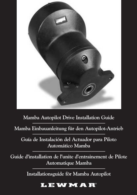
<strong>Mamba</strong> <strong>Autopilot</strong> <strong>Drive</strong> <strong>Installation</strong> <strong>Guide</strong><strong>Mamba</strong> Einbauanleitung für den <strong>Autopilot</strong>-AntriebGuía de Instalación del Actuador para PilotoAutomático <strong>Mamba</strong><strong>Guide</strong> d’installation de l’unite d’entrainement de PiloteAutomatique <strong>Mamba</strong><strong>Installation</strong>sguide för <strong>Mamba</strong> <strong>Autopilot</strong>
GBCONTENTSIntroduction . . . . . . . . . . . . . . . . . . . . . . . . . . . . . . . . . . . . . . .1Safety Notices . . . . . . . . . . . . . . . . . . . . . . . . . . . . . . . . . . . .2EMC Recommended <strong>Guide</strong>lines . . . . . . . . . . . . . . . . . . . . . . . .3Preparation . . . . . . . . . . . . . . . . . . . . . . . . . . . . . . . . . . . . . . .5Identifying the <strong>Mamba</strong> <strong>Autopilot</strong> <strong>Drive</strong> . . . . . . . . . . . . . . . . . . . .6<strong>Drive</strong> Dimensions . . . . . . . . . . . . . . . . . . . . . . . . . . . . . . . . . .7<strong>Drive</strong> Specifications . . . . . . . . . . . . . . . . . . . . . . . . . . . . . . . . .8<strong>Installation</strong> . . . . . . . . . . . . . . . . . . . . . . . . . . . . . . . . . . . . . . .13Connecting the <strong>Mamba</strong> <strong>Drive</strong> . . . . . . . . . . . . . . . . . . . . . . . . .13Mounting the drive and connecting the Steering System . . . . . .14Connecting to the Course Computer . . . . . . . . . . . . . . . . . . . .16Post installation checks . . . . . . . . . . . . . . . . . . . . . . . . . . . . .18Maintenance . . . . . . . . . . . . . . . . . . . . . . . . . . . . . . . . . . . . .18<strong>Lewmar</strong> Limited Warranty . . . . . . . . . . . . . . . . . . . . . . . . . . .19DINHALTSVERZEICHNISEinführung . . . . . . . . . . . . . . . . . . . . . . . . . . . . . . . . . . . . . . . .1Sicherheitshinweise . . . . . . . . . . . . . . . . . . . . . . . . . . . . . . . . .2Empfohlene Richtlinien zur EMV . . . . . . . . . . . . . . . . . . . . . . . .3Vorbereitung . . . . . . . . . . . . . . . . . . . . . . . . . . . . . . . . . . . . . .5Teile-Identifikation des <strong>Mamba</strong>-<strong>Autopilot</strong>-Antriebs . . . . . . . . . . .6Abmessungen des Antriebs . . . . . . . . . . . . . . . . . . . . . . . . . . .7Technische Daten des Antriebs . . . . . . . . . . . . . . . . . . . . . . . . .9Einbau . . . . . . . . . . . . . . . . . . . . . . . . . . . . . . . . . . . . . . . . . .13Verbindung des <strong>Mamba</strong>-Antriebs . . . . . . . . . . . . . . . . . . . . . .13Befestigung des Antriebs und Verbindung mit der Steueranlage . .14Verbindung zum Kursrechner . . . . . . . . . . . . . . . . . . . . . . . . .16Kontrollen nach dem Einbau . . . . . . . . . . . . . . . . . . . . . . . . . .18Wartung . . . . . . . . . . . . . . . . . . . . . . . . . . . . . . . . . . . . . . . .18Eingeschränkte Gewährleistung durch <strong>Lewmar</strong> . . . . . . . . . . . .19EÍNDICEIntroducción . . . . . . . . . . . . . . . . . . . . . . . . . . . . . . . . . . . . . . .1Avisos de Seguridad . . . . . . . . . . . . . . . . . . . . . . . . . . . . . . . .2Directrices Recomendadas para la CEM . . . . . . . . . . . . . . . . . .3Preparación . . . . . . . . . . . . . . . . . . . . . . . . . . . . . . . . . . . . . . .5Identificación del Actuador para Piloto Automático <strong>Mamba</strong> . . . .6Dimensiones del Actuador . . . . . . . . . . . . . . . . . . . . . . . . . . .8Especificaciones del Actuador . . . . . . . . . . . . . . . . . . . . . . . .10Instalación . . . . . . . . . . . . . . . . . . . . . . . . . . . . . . . . . . . . . . .13Conexión del Actuador <strong>Mamba</strong> . . . . . . . . . . . . . . . . . . . . . . .13Montaje del Actuador y conexión al Sistema de Gobierno . . . . .14Conexión al Piloto Automático . . . . . . . . . . . . . . . . . . . . . . . .16Comprobaciones después de la instalación . . . . . . . . . . . . . . .18Mantenimiento . . . . . . . . . . . . . . . . . . . . . . . . . . . . . . . . . . .18Garantía de <strong>Lewmar</strong> Limited . . . . . . . . . . . . . . . . . . . . . . . . . .19FSESOMMAIREIntroduction . . . . . . . . . . . . . . . . . . . . . . . . . . . . . . . . . . . . . . .1Notices de sécurité . . . . . . . . . . . . . . . . . . . . . . . . . . . . . . . . .2Recommandations EMC . . . . . . . . . . . . . . . . . . . . . . . . . . . . .3Préparation . . . . . . . . . . . . . . . . . . . . . . . . . . . . . . . . . . . . . . .5Identification de l’unité d’entraînement de piloteautomatique <strong>Mamba</strong> . . . . . . . . . . . . . . . . . . . . . . . . . . . . . . . .6Dimensions de l’unité . . . . . . . . . . . . . . . . . . . . . . . . . . . . . . .8Caractéristiques techniques de l’unité . . . . . . . . . . . . . . . . . . .11INNEHÅLLInledning . . . . . . . . . . . . . . . . . . . . . . . . . . . . . . . . . . . . . . . . .1Säkerhetsanmärkningar . . . . . . . . . . . . . . . . . . . . . . . . . . . . . .2EMC-rekommenderade riktlinjer . . . . . . . . . . . . . . . . . . . . . . . .3Förberedelse . . . . . . . . . . . . . . . . . . . . . . . . . . . . . . . . . . . . . .5Identifiering av <strong>Mamba</strong> <strong>Autopilot</strong>drift . . . . . . . . . . . . . . . . . . . . .6Drivsystemets mått . . . . . . . . . . . . . . . . . . . . . . . . . . . . . . . . .8Drivsystemets specifikationer . . . . . . . . . . . . . . . . . . . . . . . . .12<strong>Installation</strong> . . . . . . . . . . . . . . . . . . . . . . . . . . . . . . . . . . . . . . .13Connexion de l’unité d’entraînement <strong>Mamba</strong> . . . . . . . . . . . . . .13Montage de l’unité d’entraînement et connexion ausystème de gouvernail . . . . . . . . . . . . . . . . . . . . . . . . . . . . . .14Interface avec l’ordinateur de cap . . . . . . . . . . . . . . . . . . . . .16Vérifications après installation . . . . . . . . . . . . . . . . . . . . . . . .18Entretien . . . . . . . . . . . . . . . . . . . . . . . . . . . . . . . . . . . . . . . .18Garantie limitée <strong>Lewmar</strong> . . . . . . . . . . . . . . . . . . . . . . . . . . . .19<strong>Installation</strong> . . . . . . . . . . . . . . . . . . . . . . . . . . . . . . . . . . . . . . .13Anslutning av <strong>Mamba</strong> Drivsystem . . . . . . . . . . . . . . . . . . . . . .13Montering av drivsystemet och anslutning till styrsystemet . . . .14Anslutning till kursdatorn . . . . . . . . . . . . . . . . . . . . . . . . . . . .16Kontroller efter installationen . . . . . . . . . . . . . . . . . . . . . . . . .18Underhåll . . . . . . . . . . . . . . . . . . . . . . . . . . . . . . . . . . . . . . .18<strong>Lewmar</strong> begränsad garanti . . . . . . . . . . . . . . . . . . . . . . . . . . .19
INTRODUCTIONWelcome to the <strong>Lewmar</strong> <strong>Mamba</strong> <strong>Autopilot</strong> <strong>Drive</strong> installation guide.The product is intended to operate the boat’s steering mechanism aspart of an electronic manufacturer’s, autopilot system. It is designedfor boats with existing <strong>Mamba</strong> steering systems.Product Support: <strong>Lewmar</strong> products are supported by a worldwidenetwork of distributors and Authorised Service Representatives. Ifyou encounter any difficulties with this product, please contact yournational distributor, or your local <strong>Lewmar</strong> Dealer.To the best of our knowledge, the information in this handbookwas correct when it went to press. However, LEWMAR cannotaccept liability for any inaccuracies or omissions it may contain.In addition, our policy of continuous product improvement maychange specifications without notice. As a result, LEWMARcannot accept liability for any differences between the productand the handbook.WHITLOCK is a registered trademark of LEWMAR LIMITED.© LEWMAR LIMITED 2002.GBEINFÜHRUNGWillkommen zur Einbauanleitung für den <strong>Lewmar</strong> <strong>Mamba</strong> <strong>Autopilot</strong>-Antrieb. Dieses Produkt dient zur Betätigung der Steuervorrichtungdes Schiffes als Teil eines elektronischen <strong>Autopilot</strong>systems. Es ist fürSchiffe mit einer bestehenden <strong>Mamba</strong>-Steueranlage bestimmt.Produktunterstützung: <strong>Lewmar</strong>-Produkte werden durch einweltweites Netz von Händlern und autorisierten Servicevertretungenunterstützt. Sollten Sie auf Schwierigkeiten mit diesem Produktstoßen, setzen Sie sich bitte mit Ihrem regionalen Großhändler oderIhrem örtlichen <strong>Lewmar</strong>-Händler in Verbindung.Die Informationen in diesem Handbuch waren nach bestemWissen bei Drucklegung korrekt. Dennoch kann LEWMAR keineVerantwortung für etwaige Ungenauigkeiten oder fehlendeInformationen übernehmen. Außerdem verbessern wir ständigunsere Produkte, wodurch sich die technischen Daten ohneVorankündigung ändern können. Aus diesem Grund kannLEWMAR keine Verantwortung für jedwede Unterschiedezwischen dem Produkt und dem Handbuch übernehmen.WHITLOCK ist eine eingetragene Marke von LEWMAR LIMITED.© LEWMAR LIMITED 2002.DINTRODUCCIÓNBienvenido a la guía de instalación del Actuador para PilotoAutomático <strong>Mamba</strong> de <strong>Lewmar</strong>. El producto está destinado aaccionar el mecanismo de gobierno como parte integrante de unpiloto automático de un fabricante de equipos electrónicos. Para suuso en embarcaciones dotadas previamente con un sistema degobierno <strong>Mamba</strong>.Soporte del producto: Los productos de <strong>Lewmar</strong> están soportadospor una red mundial de Distribuidores y Servicios Técnicosautorizados. Si tiene alguna dificultad con este producto contactecon su distribuidor nacional o el revendedor de <strong>Lewmar</strong> mascercano.INTRODUCTIONBienvenu dans le <strong>Guide</strong> d‘installation de l’unité d’entraînement depilote automatique <strong>Mamba</strong> <strong>Lewmar</strong>. Ce dispositif est un élémentdu pilote automatique électronique du fabricant. Il est conçu pourêtre installé sur des bateaux possédant déjà un système degouvernail <strong>Mamba</strong>.Support commercial: Les produits <strong>Lewmar</strong> profitent du supportd’un réseau mondial de distributeurs et de concessionnaires agréés.En cas de difficultés quelles qu’elles soient concernant ce produit,veuillez contacter votre distributeur national ou le concessionnaire<strong>Lewmar</strong> local.A nuestro leal saber y entender, la información contenida eneste manual era correcta en el momento de su impresión. Sinembargo, LEWMAR no aceptará responsabilidad de ningunaclase por cualquier inexactitud u omisión que pueda contener.Además, con nuestra política de mejora continua del producto,se pueden producir cambios en las especificaciones sin previoaviso. Como resultado LEWMAR no aceptará responsabilidadalguna por diferencias entre este manual y el producto real.Whitlock es marca registrada de LEWMAR LIMITED© LEWMAR LIMITED 2002.À notre connaissance, les informations contenues dans cemanuel sont correctes au moment de l’impression. LEWMARne peut cependant accepter une quelconque responsabilité aucas où il contiendrait des inexactitudes ou omissions. De plus,notre politique d’amélioration permanente de nos produits peutentraîner des changements aux caractéristiques techniquessans préavis. De ce fait, LEWMAR ne peut accepter aucuneresponsabilité en cas de différences entre le produit le manuel.WHITLOCK est une marque déposée de LEWMAR LIMITED.© LEWMAR LIMITED 2002.EFINLEDNINGVälkommen till <strong>Lewmar</strong>s installationsguide för <strong>Mamba</strong> <strong>Autopilot</strong>.Produkten är tänkt för skötseln av båtens styrmekanism som del aven elektroniktillverkares autopilotsystem. Den har utformats för båtarmed befintliga <strong>Mamba</strong> styrsystem.Produktsupport: <strong>Lewmar</strong>s produkter understöds av ettvärldsomfattande nätverk av distributörer och auktoriseradeservicerepresentanter. Om du får några som helst problem meddenna produkt, vänligen kontakta distributören i ditt land eller dinlokala <strong>Lewmar</strong>-försäljare.Så vitt vi vet var informationen i denna manual korrekt när dengick i tryck. LEWMAR kan emellertid inte ta ansvar för eventuellafelaktigheter eller bristfälligheter som den kan innehålla. Vårkontinuerliga produktutvecklingspolicy kan därutöver leda till attspecifikationerna ändras utan förvarning. Härav följer attLEWMAR inte kan ta ansvar för eventuella skillnader mellanprodukten och manualen.WHITLOCK är ett registrerat varumärke som tillhör LEWMAR LIMITED.© LEWMAR LIMITED 2002.SE1
GBSAFETY NOTICESThis equipment must be installed and operated in accordance withthe instructions contained in this handbook. Failure to do so couldresult in poor product performance, personal injury and/or damageto your boat.Because correct performance of the boat’s steering is criticalfor safety, <strong>Lewmar</strong> STRONGLY RECOMMEND that a competentmarine installation technician fit this product.Electrical Safety:Make sure you have switched off the power supply before you startinstalling this product.Warning:Keep clear of moving steering systems at all times. Protect movingparts from access during normal use.Caution:Consult the boat manufacturer if you have any doubt about thestrength or suitability of the mounting location.DEFSE2SICHERHEITSHINWEISEDiese Anlage muss entsprechend den Anweisungen in diesemHandbuch installiert und betrieben werden. Nichtbefolgen kann dieLeistung des Produkts beeinträchtigen, Verletzungen hervorrufenund/oder das Schiff beschädigen.Da die einwandfreie Funktion der Schiffssteuerung lebenswichtigfür die Sicherheit ist, wird von <strong>Lewmar</strong> DRINGEND EMPFOHLEN,dass dieses Produkt von einem qualifizierten Fachmann fürSchiffseinrichtungen installiert wird.AVISOS DE SEGURIDADEste equipo debe ser instalado y manejado de acuerdo con lasinstrucciones contenidas en este manual. Su incumplimiento podráresultar en bajas prestaciones del producto, lesiones personales y/odaños a su embarcación.Debido al hecho de que las prestaciones correctas del sistemade gobierno de la embarcación son críticas para la seguridad,<strong>Lewmar</strong> RECOMIENDA ENÉRGICAMENTE que un técnicocompetente en instalaciones náuticas instale este producto.NOTICES DE SÉCURITÉCet équipement doit être installé et utilisé conformément auxinstructions contenues dans ce manuel. Le manquement à cetterègle pourrait être la cause d’une mauvaise performance dudispositif, de blessures personnelles et/ou de dommages au bateau.Le fonctionnement correct du système de gouvernail du bateauétant un élément essentiel de la sécurité, <strong>Lewmar</strong> RECOMMANDEFORTEMENT que ce dispositif soit installé par un technicienmarine compétent.SÄKERHETSANMÄRKNINGARDenna utrustning ska installeras och hanteras i enlighet medanvisningarna i denna manual. Försummelse av detta kan resultera inedsatta produktprestanda, personskada och/eller skador på din båt.Då det är viktigt för säkerheten att båtens styrning fungerarfelfritt vill <strong>Lewmar</strong> BESTÄMT REKOMMENDERA att denna produktmonteras av en kompetent marininstallationstekniker.Elektrische Sicherheit:Vor dem Einbau des Produkts unbedingt die Stromversorgungabschalten.Warnung:Stets von sämtlichen beweglichen Teilen der Steueranlagefernbleiben. Bewegliche Teile während des Normalbetriebs vorZugriff schützen.Vorsicht:Erkundigen Sie sich beim Hersteller des Schiffes, falls Zweifel überdie Festigkeit oder Eignung der Montageposition bestehen.Seguridad Eléctrica:Asegúrese de haber desconectado el suministro de potenciaeléctrica antes de empezar a instalar el producto.Aviso:Manténgase alejado de los sistemas de gobierno móviles en todomomento. Proteja el acceso a las partes móviles durante el usonormal.Precaución:Consulte al fabricante de la embarcación su tuviere cualquier dudasobre la resistencia o idoneidad de la localización para el montaje.Securite De L’alimentation Electrique:S’assurer que l’alimentation électrique soit en position éteinte avantde commencer à installer ce dispositif.Avertissement:Il faut à tout moment se tenir à distance des parties mouvantes dusystème de gouvernail. Protéger l’accès aux parties mouvantes encours de fonctionnement normal.Attention:Consulter le fabricant du bateau en cas de doute sur la résistanceou la convenance de l’emplacement de l’installation de l’unité.Elsäkerhet:Förvissa dig om att strömförsörjningen är avstängdinnan du börjar installera denna produkt.Varning:Håll alltid avstånd till styrsystem som är i rörelse. Se till att rörligadelar inte går att nå under normal användning.Försiktighet:Hör med båtens tillverkare om du har några som helst tvivelangående monteringsplatsens styrka eller lämplighet.
EMC RECOMMENDED GUIDELINESAll <strong>Lewmar</strong> equipment and accessories are designed to conform tothe appropriate Electromagnetic Compatibility (EMC) standards.Correct installation is required to ensure that performance is notcompromised.The guidelines given here describe the conditions for optimum EMCperformance, but it is recognised that it may not be possible tomeet all of these conditions in all situations. To ensure the bestpossible conditions for EMC performance within the constraintsimposed by any location, always ensure the maximum separationpossible between different items of electrical equipment.For optimum EMC performance, it is recommended that whereverpossible:<strong>Lewmar</strong> equipment and cables connected to it are:• At least 3ft (1m) from any equipment transmitting or cablescarrying radio signals e.g. VHF radios, cables and antennas.In the case of SSB radios, the distance should be increasedto 7ft (2m).GBEMPFOHLENE RICHTLINIEN ZUR EMVAlle Einrichtungen und sämtliches Zubehör von <strong>Lewmar</strong> sindentsprechend den einschlägigen Normen zur elektromagnetischenVerträglichkeit (EMV) konzipiert. Jedoch ist ein korrekter Einbauerforderlich, damit dieses Leistungsmerkmal nichtbeeinträchtigt wird.Die hier angegebenen Richtlinien beschreiben die Bedingungen zuroptimalen EMV-Leistung. Es ist jedoch möglich, dass nicht jededieser Bedingungen in allen Situationen erfüllt werden kann. Umbestmögliche Bedingungen für die EMV-Leistung innerhalb derGegebenheiten eines Standorts zu gewährleisten, sollten dieverschiedenen Teile einer elektrischen Anlage so weit wie möglichvoneinander getrennt angeordnet werden.Für optimale EMV-Leistung sind folgende Empfehlungenmöglichst jederzeit zu beachten:<strong>Lewmar</strong>-Anlagen und Kabelverbindungen:• Mindestens 1 m von allen Geräten, welche Funksignaleaussenden, oder von Kabeln, welche Funksignale führen, z.B.UKW-Funkanlagen, -Kabel und -Antennen. Bei ESB-Funkanlagensollte der Abstand auf 2 m vergrößert werden.DDIRECTRICES RECOMENDADAS DE CEMTodos los equipos y accesorios de <strong>Lewmar</strong> están diseñados paracumplir la normativa vigente de CEM (Compatibilidadelectromagnética). Se requiere una correcta instalación para quedichas prestaciones no queden disminuidas.Las directrices aquí indicadas describen las condiciones para unaprestaciones de CEM óptimas, pero se reconoce que puede serimposible cumplir todas estas condiciones en todas las situacionesposibles. Para asegurar las máximas prestaciones de CEM con lasrestricciones impuestas por la situación de los equipos, maximicesiempre la separación entre los mismos.Para óptimas prestaciones de CEM se recomienda, siempre quesea posible, que:los equipos <strong>Lewmar</strong> y sus cables conexión estén• A una distancia de al menos 1 m. de cualquier equipo detransmisión y de cables portadores de señales de radio, por ej.radios de VHF, cables y antenas. En el caso de radios BLU ladistancia se debe incrementar a 2 m.ERECOMMANDATIONS EMCTous les équipements et accessoires <strong>Lewmar</strong> sont conçusconformément aux normes de compatibilité électromagnétique(EMC). Il est essentiel que l’installation soit effectuée correctementafin de ne pas compromettre la performance.Les recommandations ci-dessous décrivent les conditions requisespour obtenir une performance EMC optimale, mais il est entenduqu’il est possible de remplir toutes ces conditions quelle que soit lasituation. Pour garantir les meilleures conditions possibles deperformance EMC dans les limites imposées par l’emplacement del’installation, s’assurer que la séparationentre les différents composants électriques soit toujours la plusgrande possible.Pour une performance EMC optimale, il est recommandé dans lamesure du possible que :Les équipements <strong>Lewmar</strong> et les câbles de branchement soient :• À au moins 1m de tout élément émetteur de signal ou de toutcâble transmettant des signaux radiophoniques, comme parexemple une radio VHF, ses câbles et son antenne. Dans le casd’une radio BLU, la distance recommandée est de 2m.FEMC-REKOMMENDERADE RIKTLINJERAlla <strong>Lewmar</strong>s utrustningar och tillbehör är utformade för att uppfyllagällande normer för elektromagnetisk kompatibilitet (EMC). Enkorrekt installation krävs för att prestandan inte ska äventyras.De riktlinjer som ges här beskriver betingelserna för en optimalelektromagnetisk kompatibilitet, men vi förstår att det kan varaomöjligt att uppnå alla dessa betingelser i samtliga lägen. För att denelektromagnetiska kompatibiliteten ska få bästa möjligaförutsättningar, inom de begränsningar som all placering ger, är detviktigt att alltid se till att den elektriska utrustningens olika delar stårså långt isär som möjligt.För optimala EMC-prestanda rekommenderas, där så är möjligt:Att <strong>Lewmar</strong>-utrustning och kablar som ansluts till dessa placeras:• Minst 1m från all utrustning eller kablar som sänder ut eller bärradiosignaler, t.ex. VHF-radioapparater, kablar och antenner. Vidanvändning av SSB-radioapparater bör avståndet ökas till 2m.SE3
GB• More than 7ft (2m) from the path of a radar beam. A radar beamcan normally be assumed to spread 20° above and below theradiating element.• The equipment is supplied from a separate battery from thatused for engine start. Voltage drops below 10V, and startermotor transients, can cause the equipment to reset. This will notdamage the equipment, but may cause the loss of someinformation and may change the operating mode.OTHER INFORMATION(Applies to all drives)Protected for use in engine compartmentsCE approvals – conforms to:89/336/EC (EMC), BS EN60945:199794/25/ec (RCD), BS EN28846:1993D• Mehr als 2 m vom Verlauf eines Radarstrahls. Ein Radarstrahlbreitet sich normalerweise 20° oberhalb und unterhalb desAbstrahlelements aus.• Die Anlage wird von einer separaten Batterie gespeist, die nichtzum Anlassen des Motors verwendet wird. DurchSpannungsabfälle unter 10 V und Übergangsspannungen desMotoranlassers könnten die Einstellwerte der Anlagezurückgesetzt werden. Hierdurch wird die Anlage zwar nichtbeschädigt, jedoch könnten Informationen verloren gehen unddie Betriebsart geändert werden.WEITERE INFORMATIONEN(Alle Antriebe betreffend)Zur Anwendung in Motorräumen geschütztCE-Zulassungen gemäß:89/336/EC (EMC), BS EN60945:199794/25/ec (RCD), BS EN28846:1993E• A mas de 2 m. del trayecto de un haz radárico. Se supone queun haz radárico normalmente puede extenderse 20º por encima ypor debajo del elemento emisor.• Y que los equipos se alimenten de baterías diferentes de lasusadas para el arranque del motor. Caídas de voltaje por debajode los 10V o corrientes transitorias de los motores de arranquepueden causar la reinicialización de los equipos y cambiar sumodo de funcionamiento.OTRAS INFORMACIONES(Aplicable a todos los actuadores)Protegido para su uso en salas de máquinasHomologaciones de la CE. – cumple con:89/336/EC (EMC), BS EN60945:199794/25/ec (RCD), BS EN28846:1993F• À plus de 2m du passage d’un faisceau radar. Il faut estimerqu’un faisceau radar s’étend normalement à 20° au-dessus et endessous de l’axe horizontal du radôme.• L’alimentation de cet équipement soit fournie par une batterieséparée de celle qui alimente le démarrage du moteur. Une chutede tension inférieure à 10v et les pointes causées par ledémarreur peuvent entraîner la réinitialisation du système. Cecine cause aucun dommage aux équipements mais peut provoquerla perte d’informations ou changer le mode opérationnel.INFORMATIONS SUPPLÉMENTAIRES(S’applique à tous les systèmes de transmission)Protégé pour utilisation dans le compartiment moteurApprouvé CE – conforme aux normes :89/336/EC (EMC), BS EN60945:199794/25/ec (RCD), BS EN28846:1993SE• Mer än 2m från den väg en radarpuls tar. En radarpuls kan ivanliga fall antas sprida sig 20° ovanför och under detpulsgivande instrumentet.• Att utrustningen försörjs från ett annat batteri än det somanvänds för att starta motorn. Spänningsfall under 10V ochstartmotortransienter kan leda till att utrustningen återställs. Dettaskadar inte utrustningen, men kan göra att viss information gårförlorad och att driftssättet ändras.ANNAN INFORMATION(Gäller samtliga drivsystem)Skyddad för användning i motorrumCE-godkännanden – uppfyller:89/336/EC (EMC), BS EN60945:199794/25/ec (RCD), BS EN28846:19934
PREPARATIONStructural strength:• The <strong>Mamba</strong> drive mounts directly to the steering system’s bevelhead or reduction gearbox, via an interface plate.• To prevent excess noise and vibration, do not attach this drive toany structures that support cabins.• The <strong>Mamba</strong> drive is designed for mounting directly onto abevelhead or reduction gearbox in the steering system, structuralmounting instructions will apply chiefly to the gearbox that theautopilot is mounted to.<strong>Drive</strong> orientation:• <strong>Mamba</strong> drives can be installed in any attitude directly onto themounting flange on the bevel head or reduction gearbox.General position:• Refer to the EMC installation guidelines (page 3)• Make sure the drive will be accessible for future servicing.Environment:• This drive is not waterproof, so you should mount it in a drylocation, clear of any bilge water.GBVORBEREITUNGBaufestigkeit:• Der <strong>Mamba</strong>-Antrieb wird über eine Zwischenplatte direkt amKegelkopf oder Untersetzungsgetriebe der Steueranlage befestigt.• Um starke Lärmentwicklung und Vibration zu vermeiden, darf derAntrieb an keinen kabinentragenden Strukturen befestigt werden.• Der <strong>Mamba</strong>-Antrieb ist für den direkten Anbau an einemKegelkopf oder Untersetzungsgetriebe in der Steueranlagekonzipiert. Die Einbauanleitung bezieht sich in erster Linie auf dasGetriebe, auf dem der <strong>Autopilot</strong> befestigt ist.PREPARACIÓNResistencia estructural:• El Actuador <strong>Mamba</strong> se monta directamente en una caja detransmisión en ángulo o caja reductora del sistema de gobierno,mediante una placa de interface.• Para evitar de ruidos y vibraciones excesivos, no acoplar elactuador a cualquier estructura de soporte de cabinas.• El actuador <strong>Mamba</strong> está diseñado para su montaje directo sobreuna caja de transmisión en ángulo o caja reductora del sistemade gobierno. Las instrucciones para el montaje estructural seaplicarán principalmente a la caja sobre la que se monta elactuador para piloto automático.PRÉPARATIONRésistance structurelle :• L’unité d’entraînement <strong>Mamba</strong> se monte directement sur lepignon conique du système de gouvernail ou sur le réducteur parune plaque d’interface.• Pour éviter tout excès de bruit et les vibrations, ne pas monter cesystème sur une structure qui supporte les cabines..• L’unité d’entraînement <strong>Mamba</strong> est conçue pour être installéedirectement sur un pignon conique ou sur le réducteur dusystème de gouvernail. Les instructions structurelles de montages’appliquent principalement au réducteur sur lequel le piloteautomatique est connecté.FÖRBEREDELSEStrukturell styrka:• <strong>Mamba</strong> drivsystem monteras direkt på styrsystemets koniskaeller reducerande växellåda, via en kontaktplatta.• För att förebygga onödigt oväsen och vibrationer, fäst inte dettadrivsystem vid några strukturer som tjänar som stöd åt kabiner.• <strong>Mamba</strong> drivsystem är avsedd för montering direkt på en koniskeller reducerande växellåda i styrsystemet; strukturellamonteringsanvisningar kommer främst att gälla den växellådasom autopiloten är monterad på.Antriebsausrichtung:• <strong>Mamba</strong>-Antriebe können in jeder Position direkt auf demMontageflansch des Kegelkopfes oder desUntersetzungsgetriebes installiert werden.Allgemeine Position:• Siehe Einbaurichtlinien bzgl. EMV (Seite 3).• Sicherstellen, dass der Antrieb für spätere Wartungsarbeitenzugänglich ist.Umgebung:• Der Antrieb ist nicht wasserfest. Er sollte daher an einemtrockenen Ort montiert werden, der frei von Bilgewasser ist.Orientación del actuador:• Las transmisiones <strong>Mamba</strong> se pueden instalar en cualquierorientación directamente sobre la brida de montaje de la caja detransmisión en ángulo o caja reductora.Posición general:• Refiérase a las directrices de instalación para la CEM (página 3)• Asegúrese de que el Actuador sea accesible para sumantenimiento.Medio ambiente:• Este Actuador no es estanco, y por lo tanto deberá montarse enun lugar seco, libre de aguas de sentina.Orientation de l’unité :• L’unité d’entraînement <strong>Mamba</strong> peut être installée dans n’importequelle orientation directement sur la bride de montage du pignonconique ou du réducteur.Position générale :• Se reporter au guide d’installation EMC installation (page 3)• S’assurer que le système de transmission est accessible pourles révisions futures.Environnement:• Ce système de transmission n’est pas étanche, il doit donc êtreinstallé dans un endroit sec, à l’abri de l’eau des cales.Drivsystemets orientering:• <strong>Mamba</strong> drivsystem kan installeras i alla ställningar direkt påmonteringskanten av den koniska eller reducerande växellådan.Allmän placering:• Se EMC-installationsriktlinjerna (sidan )• Förvissa dig om att drivsystemet kan nås för framtida underhåll.Miljö:• Detta drivsystem är inte vattentätt; du bör därför montera det påen torr plats där det inte utsätts för eventuellt slagvatten.DEFSE5
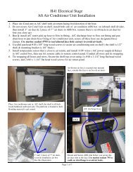
GBIDENTIFYING THE MAMBA DRIVE —FIGURE 1A. Motor Gearbox and Clutch AssemblyB. Motor CableC. Clutch CableD. Mounting FaceDTEILE-IDENTIFIKATION DES MAMBA-ANTRIEBS — ABBILDUNG 1A. Motorgetriebe und -KupplungB. MotorkabelC. KupplungskabelD. MontageflächeAEIDENTIFICACIÓN DEL ACTUADORMAMBA — FIGURA 1A. Conjunto de caja reductora y embraguedel motorB. Cable del motorC. Cable del embragueD. Superficie de montajeBFIDENTIFICATION DE L’UNITÉD’ENTRAÎNEMENT MAMBA —FIGURE 1CDA. Ensemble Moteur, Réducteur Et EmbrayageB. Câble du MoteurC. Câble de L’embrayageD. Plaque de MontageSEIDENTIFIERING AV MAMBADRIVSYSTEM — FIGURE 1A. Motorns Växellåda och KopplingB. MotorkabelC. KopplingskabelD. Monteringssida6
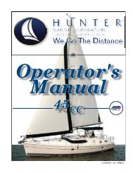
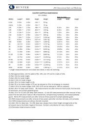
SN155/255 - 256mmSN355 - 277mmDRIVE DIMENSIONS —FIGURE 2A. 2 Holes Helicoiled M10(Thru' hole optional)GBABMESSUNGEN DES ANTRIEBS —ABBILDUNG 2A. 2 m10-gewindebohrungen(durchgangsloch wahlweise)DDIMENSIONES DEL ACTUADOR —FIGURA 2A. 2 orificios dotados de helicoils de M10(opcionalmente orificios pasantes)ESN155/255 - 188mmSN355 - 210mmDIMENSIONS DE L’UNITÉ —FIGURE 2A. 2 trous hélicoïdes m10(trous traversiers en option)F55mmADRIVSYSTEMETS MÅTT —FIGURE 2SE163mmA. 2 hål skruvformiga m10(genom hål valfritt)7
DTECHNISCHE DATEN DES ANTRIEBSTeile-nummer Bezeichnung PS Volt Max.Dreh-momentLeerlaufdrehzahlMax. RuderdrehmomentMittl. StromaufnahmeCircuitBreakerGewichtGeeignet fürSchiffs-größeft lbs Nm ft lbs MKG Motor Clutch kg lb89300051 <strong>Mamba</strong> 1/8hp 12v Std 1/8 12 70 95 10 988 138 4A 16A 1,5A 8 17,689300052 <strong>Mamba</strong> 1/8hp 24v Compact 1/8 24 70 95 10 988 138 4A 10A 2A 8 17,6Bis11,6m(38')89300053 <strong>Mamba</strong> 1/4hp 12v Std 1/4 12 125 169 10 1794 248 4A 16A 3A 9 19,889300054 <strong>Mamba</strong> 1/4hp 24v Std 1/4 24 125 169 10 1794 248 2,5A 10A 2A 9 19,889300055 <strong>Mamba</strong> 1/4hp 2412v Std 1/4 24/12 125 169 10 1794 248 2,5/4A 10A 3A 9 19,889300056 <strong>Mamba</strong> 1/4hp 12v Compact 1/4 12 125 169 10 1794 248 4A 16A 3A 9 19,8Bis16,75m(60')89300057 <strong>Mamba</strong> 1/4hp 24v Compact 1/4 24 125 169 10 1794 248 2,5A 10A 2A 9 19,889300058 <strong>Mamba</strong> 1/4hp 2412v Compact 1/4 24/12 125 169 10 1794 248 2,5/4A 10A 3A 9 19,889300059 <strong>Mamba</strong> 1/4hp 12v Std Bavaria 1/4 12 125 169 10 1794 248 4A 16A 3A 9 19,889300060 <strong>Mamba</strong> 1/2hp 24v Std 1/2 24 135 183 10 3080 426 3,5A 16A 2A 10,5 23,189300061 <strong>Mamba</strong> 1/2hp 2412v Std 1/2 24 135 183 10 3080 426 3,5A 16A 3A 10,5 23,1Bis24,4m(80')89300062 <strong>Mamba</strong> 1/2hp 24v Compact 1/2 24 135 183 13 3080 426 3,5A 16A 2A 10,5 23,189300063 <strong>Mamba</strong> 1/2hp 2412v Compact 1/2 24/12 135 183 13 3080 426 3,5A 16A 3A 10,5 23,189300064 <strong>Mamba</strong> 1hp 24v c/w bed plate 1 24 344 466 18 12055 1660 6,A 32A 2A 30 66,1Over24.4m (80')9
10EESPECIFICACIONES DEL ACTUADORReferencia Descripción C.V.(H.P.)Voltiosmotor/embr.Par Máximodel MotorVelocidadSin CargaRPMPar Máximodel TimónConsumoMedioFusiblelibras/pie Nm libras pie KgM Motor Embr. kg lbPesoGuía deTamaños deEmbarcación89300051 <strong>Mamba</strong> 1/8hp 12v Estandard 1/8 12 70 95 10 988 138 4A 16A 1,5A 8 17,689300052 <strong>Mamba</strong> 1/8hp 24v Compact 1/8 24 70 95 10 988 138 4A 10A 2A 8 17,6Hasta11,6m (38')89300053 <strong>Mamba</strong> 1/4hp 12v Estandard 1/4 12 125 169 10 1794 248 4A 16A 3A 9 19,889300054 <strong>Mamba</strong> 1/4hp 24v Estandard 1/4 24 125 169 10 1794 248 2,5A 10A 2A 9 19,889300055 <strong>Mamba</strong> 1/4hp 2412v Estandard 1/4 24/12 125 169 10 1794 248 2,5/4A 10A 3A 9 19,889300056 <strong>Mamba</strong> 1/4hp 12v Compact 1/4 12 125 169 10 1794 248 4A 16A 3A 9 19,8Hasta16,75m(60')89300057 <strong>Mamba</strong> 1/4hp 24v Compact 1/4 24 125 169 10 1794 248 2,5A 10A 2A 9 19,889300058 <strong>Mamba</strong> 1/4hp 2412v Compact 1/4 24/12 125 169 10 1794 248 2,5/4A 10A 3A 9 19,889300059 <strong>Mamba</strong> 1/4hp 12v Estandard Bavaria 1/4 12 125 169 10 1794 248 4A 16A 3A 9 19,889300060 <strong>Mamba</strong> 1/2hp 24v Estandard 1/2 24 135 183 10 3080 426 3,5A 16A 2A 10,5 23,189300061 <strong>Mamba</strong> 1/2hp 2412v Estandard 1/2 24 135 183 10 3080 426 3,5A 16A 3A 10,5 23,1Hasta24,4m(80')89300062 <strong>Mamba</strong> 1/2hp 24v Compact 1/2 24 135 183 13 3080 426 3,5A 16A 2A 10,5 23,189300063 <strong>Mamba</strong> 1/2hp 2412v Compact 1/2 24/12 135 183 13 3080 426 3,5A 16A 3A 10,5 23,189300064 <strong>Mamba</strong> 1hp 24v c/w bed plate 1 24 344 466 18 12055 1660 6,A 32A 2A 30 66,1> 24.4m(80')
11FCARACTÉRISTIQUES TECHNIQUES DE L’UNITÉNuméro depièceDescription cv Volts Couple de sortie max. Vitesse Couple max. Consommation CircuitPoidshorschargesur mèche moyenne Breakerft lbs Nm tr/min ft lbs mkg Motor Clutch kg lb<strong>Guide</strong>de taille debateau89300051 <strong>Mamba</strong> 1/8hp 12v Std 1/8 12 70 95 10 988 138 4A 16A 1,5A 8 17,689300052 <strong>Mamba</strong> 1/8hp 24v Compact 1/8 24 70 95 10 988 138 4A 10A 2A 8 17,6Jusqu’à11,60m(38')89300053 <strong>Mamba</strong> 1/4hp 12v Std 1/4 12 125 169 10 1794 248 4A 16A 3A 9 19,889300054 <strong>Mamba</strong> 1/4hp 24v Std 1/4 24 125 169 10 1794 248 2,5A 10A 2A 9 19,889300055 <strong>Mamba</strong> 1/4hp 2412v Std 1/4 24/12 125 169 10 1794 248 2,5/4A 10A 3A 9 19,889300056 <strong>Mamba</strong> 1/4hp 12v Compact 1/4 12 125 169 10 1794 248 4A 16A 3A 9 19,8Jusqu’à16,75m(60')89300057 <strong>Mamba</strong> 1/4hp 24v Compact 1/4 24 125 169 10 1794 248 2,5A 10A 2A 9 19,889300058 <strong>Mamba</strong> 1/4hp 2412v Compact 1/4 24/12 125 169 10 1794 248 2,5/4A 10A 3A 9 19,889300059 <strong>Mamba</strong> 1/4hp 12v Std Bavaria 1/4 12 125 169 10 1794 248 4A 16A 3A 9 19,889300060 <strong>Mamba</strong> 1/2hp 24v Std 1/2 24 135 183 10 3080 426 3,5A 16A 2A 10,5 23,189300061 <strong>Mamba</strong> 1/2hp 2412v Std 1/2 24 135 183 10 3080 426 3,5A 16A 3A 10,5 23,1Jusqu’à24,40m(80')89300062 <strong>Mamba</strong> 1/2hp 24v Compact 1/2 24 135 183 13 3080 426 3,5A 16A 2A 10,5 23,189300063 <strong>Mamba</strong> 1/2hp 2412v Compact 1/2 24/12 135 183 13 3080 426 3,5A 16A 3A 10,5 23,189300064 <strong>Mamba</strong> 1hp 24v c/w bed plate 1 24 344 466 18 12055 1660 6,A 32A 2A 30 66,1Over24.4m (80')
12SECARACTÉRISTIQUES TECHNIQUES DE L’UNITÉArtikelnummerBeskrivning hk Volt Maximalt utgåendevridmomentTomgångshastighetMax. rodervridmomentvarv/minGenomsnittligströmförbrukningCircuitBreakerft lbs Nm ft lbs MKG Motor Clutch kg lbVikt<strong>Guide</strong> betr.båtstorlek89300051 <strong>Mamba</strong> 1/8hp 12v Std 1/8 12 70 95 10 988 138 4A 16A 1,5A 8 17,689300052 <strong>Mamba</strong> 1/8hp 24v Compact 1/8 24 70 95 10 988 138 4A 10A 2A 8 17,6Upp till11,6m(38’)89300053 <strong>Mamba</strong> 1/4hp 12v Std 1/4 12 125 169 10 1794 248 4A 16A 3A 9 19,889300054 <strong>Mamba</strong> 1/4hp 24v Std 1/4 24 125 169 10 1794 248 2,5A 10A 2A 9 19,889300055 <strong>Mamba</strong> 1/4hp 2412v Std 1/4 24/12 125 169 10 1794 248 2,5/4A 10A 3A 9 19,889300056 <strong>Mamba</strong> 1/4hp 12v Compact 1/4 12 125 169 10 1794 248 4A 16A 3A 9 19,8Upp till16,75m(60 )89300057 <strong>Mamba</strong> 1/4hp 24v Compact 1/4 24 125 169 10 1794 248 2,5A 10A 2A 9 19,889300058 <strong>Mamba</strong> 1/4hp 2412v Compact 1/4 24/12 125 169 10 1794 248 2,5/4A 10A 3A 9 19,889300059 <strong>Mamba</strong> 1/4hp 12v Std Bavaria 1/4 12 125 169 10 1794 248 4A 16A 3A 9 19,889300060 <strong>Mamba</strong> 1/2hp 24v Std 1/2 24 135 183 10 3080 426 3,5A 16A 2A 10,5 23,189300061 <strong>Mamba</strong> 1/2hp 2412v Std 1/2 24 135 183 10 3080 426 3,5A 16A 3A 10,5 23,1Upp till24,4m(80’)89300062 <strong>Mamba</strong> 1/2hp 24v Compact 1/2 24 135 183 13 3080 426 3,5A 16A 2A 10,5 23,189300063 <strong>Mamba</strong> 1/2hp 2412v Compact 1/2 24/12 135 183 13 3080 426 3,5A 16A 3A 10,5 23,189300064 <strong>Mamba</strong> 1hp 24v c/w bed plate 1 24 344 466 18 12055 1660 6,A 32A 2A 30 66,1Over24.4m (80')
INSTALLATIONParts supplied:• <strong>Mamba</strong> drive• suitable securing bolts with washers and lock-nutsFurther Requirements:• A <strong>Mamba</strong> system bevelhead or reduction gearbox with therelevant drive interface plate. (Return gearbox for conversion ifnecessary.)• Suitable cable and electrical connectors for the drive motor andclutch (see page 17)• Before installation a smear of grease onto the drive output shaft,is recommended.Note: Make sure you have obtained these additional parts beforeyou start installation.MOUNTING THE DRIVE AND CONNECTING THESTEERING SYSTEM• The autopilot drive connects to the steering system via thesplined output shaft of a bevel-head or gearbox. The autopilotpushes over this shaft and is fixed in place with two M10 bolts.GBEINBAULieferumfang:• <strong>Mamba</strong>-Antrieb• passende Befestigungsschrauben mit Unterlegscheiben undSicherungsmutternZusätzliche Arbeitsmittel:• Ein <strong>Mamba</strong>-Kegelkopf oder -Untersetzungsgetriebe mit derpassenden Antriebszwischenplatte. (Getriebe nötigenfalls zumUmbau einsenden.)• Passende Kabel und Stecker für Antriebsmotor und Kupplung(siehe Seite 17)• Vor dem Einbau empfiehlt es sich, die Abtriebswelle des Antriebszu schmieren.Hinweis: Diese zusätzlich erforderlichen Arbeitsmittel sind vorBeginn des Einbaus bereitzustellen.BEFESTIGUNG DES ANTRIEBS UND VERBINDUNG MITDER STEUERANLAGE• Der <strong>Autopilot</strong>-Antrieb wird mit der Steueranlage über dieverzahnte Abtriebswelle eines Kegelkopfes oder Getriebesverbunden. Der <strong>Autopilot</strong> wird auf die Welle geschoben und mitzwei M10-Schrauben fixiert.DINSTALACIÓNComponentes suministrados:• Transmisión <strong>Mamba</strong>• pernos de fijación adecuados con arandelas y contratuercasOtros Requisitos:• Una caja de transmisión en ángulo o caja reductora del sistema<strong>Mamba</strong> con la placa de interface del actuador correspondiente.(Devolver la caja reductora para su transformación, si fuerenecesario.)• Cables eléctricos y conectores adecuados para el motor y elembrague del actuador (ver página 17)• Antes de la instalación se recomienda engrasar el eje detransmisión del actuador.Nota: Asegúrese de disponer los componentes adicionales antes deempezar la instalación.MONTAJE DEL ACTUADOR Y CONEXIÓN AL SISTEMADE GOBIERNO• El actuador del piloto automático se conecta al sistema degobierno a través de un eje de transmisión estriado de una cajade transmisión en ángulo o caja reductora. El actuador parapiloto automático se acopla a este eje y se fija en posición conlos dos pernos de M10.EINSTALLATIONPièces fournies :• Unité d’entraînement <strong>Mamba</strong>• Boulons de fixation appropriés avec rondelles et écrousbloqueursAutres composants requis :• Un pignon conique ou réducteur <strong>Mamba</strong> avec la plaqued’interface avec l’unité d’entraînement correspondante.(Renvoyer le réducteur pour modification au besoin.)• Connecteurs et câbles électriques appropriés pour le moteur etl’embrayage de l’unité d’entraînement (voir page 17)• Il est recommandé d’étaler une couche légère de graisse surl’arbre d’entraînement de l’unité avant l’installation.Note : S’assurer de se procurer ces pièces supplémentaires avantde commencer l’installation.MONTAGE DE L’UNITÉ D’ENTRAÎNEMENT ETCONNEXION DU SYSTÈME DE GOUVERNAIL• Le pilote automatique se connecte au système de gouvernail parl’arbre de sortie cannelé d’un pignon conique ou d’un réducteur.Le pilote automatique se pose sur cet arbre et il est maintenu enplace par deux boulons M10.FINSTALLATIONMedföljande delar:• <strong>Mamba</strong> drivsystem• lämpliga säkringsbultar med brickor och låsmuttrarYtterligare krav:• En <strong>Mamba</strong> konisk eller reducerande växellåda med den relevantadrivkontaktplattan. (Skicka tillbaka växellådan för ombyggnad omså behövs.)• Passande kabel och elektriska anslutningar till drivmotor ochkoppling (se sidan 17)• Före installationen rekommenderas att driveffektsaxeln smörjs in.Obs: Se till att du har inskaffat dessa extradelar innan du påbörjarinstallationen.MONTERING AV DRIVSYSTEMET OCH ANSLUTNING TILLSTYRSYSTEMET• <strong>Autopilot</strong>driften är ansluten till styrsystemet via den skarvadeeffektaxeln på en konisk eller reducerande växellåda. <strong>Autopilot</strong>enför undan denna axel och fästs på plats med två M10-bultar.SE13
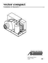
GB• The gearbox onto which the drive is to be attached must be fittedwith the drive interface plate (see Figure 3). If there is nointerface plate already included in the steering system, thegearbox can be returned to our factory for adaptation at theowner’s cost.• Complete a steering checkMounting locationBefore you secure the drive to your boat, you must first check thesuitability of the mounting location.WARNING: Keep clear of moving steering systems at all times.Protect moving parts from access during normal use.AN EXAMPLE OF HOW THEMAMBA DRIVE CAN BE INSTALLED INTO THESTEERING SYSTEM — FIGURE 3A. Typical installation of <strong>Mamba</strong> <strong>Drive</strong>(onto Bevelhead BH130 Gearbox)B. Mounting plates for coupling <strong>Mamba</strong> <strong>Drive</strong> to Bevelhead(BH130) GearboxC. Typical installation of <strong>Mamba</strong> <strong>Drive</strong> (onto Bevelhead BH130Gearbox) Compact version.DEFSE•Das Getriebe, an dem der Antrieb befestigt wird, muss mit derAntriebszwischenplatte versehen sein (siehe Abbildung 3). Fallsdie Steueranlage noch keine Zwischenplatte enthält, kann dasGetriebe an unser Werk eingeschickt werden, wo es auf Kostendes Kunden nachgerüstet wird.• Steuerkontrolle vornehmen.MontagepositionBevor der Antrieb am Schiff befestigt wird, ist zunächst die Eignungder gewählten Montageposition zu überprüfen.WARNUNG: Stets von sämtlichen beweglichen Teilen derSteueranlage fernbleiben. Bewegliche Teile während desNormalbetriebs vor Zugriff schützen.• La caja sobre la que se quiere acoplar la transmisión debe irequipada con una placa de interface para el actuador (ver Figura 3).Si no existe ninguna placa de interface incluida en el sistema degobierno, se puede devolver una caja de transmisión o reductora anuestra fábrica para su adaptación a cargo del propietario.• Realice una comprobación del funcionamiento del sistema degobierno.Localización del montajeAntes de instalar la transmisión en su embarcación, en primer lugardebe comprobar la idoneidad de la localización para su montaje.AVISO: Manténgase alejado de los sistemas de gobierno móviles entodo momento. Proteja las partes móviles contra el acceso durantesu uso normal.• Le réducteur sur lequel l’unité d’entraînement doit être connectédoit être équipé de la plaque d’interface (voir Figure 3). Si lesystème de gouvernail existant ne comprend pas encore deplaque d’interface, le réducteur peut être retourné à notre usinepour être modifié aux frais du propriétaire.• Effectuer un test de gouvernailEmplacement de montageAvant d’effectuer l’installation de l’unité d’entraînement sur le bateau, ilfaut d’abord s’assurer que l’emplacement de montage est approprié.AVERTISSEMENT : Il faut à tout moment se tenir à distance desparties mouvantes du système de gouvernail. Protéger l’accès auxparties mouvantes en cours de fonctionnement normal.• Drivkontaktplattan måste fästas till den växellåda på vilkendrivsystemet är fäst (se Figur 3). Om ingen kontaktplatta redanfinns inbyggd i styrsystemet kan växellådan skickas tillbaka tillvår industrianläggning för anpassning på ägarens bekostnad.• Utför en styrkontrollMonteringsplatsInnan du gör fast drivsystemet till din båt måste du först kontrolleramonteringsplatsens lämplighet.VARNING: Håll alltid avstånd till styrsystem som är i rörelse. Se tillatt rörliga delar inte går att nå under normal användning.EISPIEL ZUM EINBAU DES MAMBA-ANTRIEBS INDER STEUERANLAGE — ABBILDUNG 3A. Typischer einbau des mamba-antriebs(auf kegelkopfgetriebe bh130)B. Montageplatten zur kopplung des mamba-antriebs mit demkegelkopfgetriebe bh130C. Typischer einbau des mamba-antriebs (aufkegelkopfgetriebe bh130) kompaktversionEJEMPLO DE COMO INSTALAR EL ACTUADORMAMBA EN EL SISTEMA DE GOBIERNO —FIGURA 3A. Instalación típica del Actuador <strong>Mamba</strong> (sobre la caja detransmisión a 90º BH130)B. Placas de montaje para acoplar el actuador <strong>Mamba</strong> a lacaja de transmisión a 90º (BH130)C. Instalación típica del actuador <strong>Mamba</strong> (sobre la caja detransmisión a 90º BH130) versión compactaEXEMPLES D’INSTALLATION DE L’UNITÉD’ENTRAÎNEMENT MAMBA SUR LE SYSTÈME DEGOUVERNAIL — FIGURE 3A. <strong>Installation</strong> typique de l’unité d’entrainement mamba(sur réducteur a pignon conique bh 130)B. Plaque de montage pour l’accouplement de l’unitéd’entrainement au pignon conique (bh130) du réducteurC. <strong>Installation</strong> typique de l’unité d’entrainement mamba(sur réducteur a pignon conique bh 130) (versioncompacte)ETT EXEMPEL PÅ HUR MAMBA DRIVSYSTEM KANINSTALLERAS I STYRSYSTEMET — FIGUR 3A. Vanlig installation av mambadrift(på konisk bh130 växellåda)B. Monteringsplattor för koppling av mambadrift till konisk(bh130) växellådaC. Vanlig installation av mambadrift (på konisk bh130växellåda) Kompakt version14
GBADEBFCSE15
GBDECONNECTING TO THE COURSE COMPUTERWARNING: Electrical safetyMake sure the power supply is switched off before youmake any electrical connections.The drive has electrical connections for:• <strong>Drive</strong> motor: two single-core cables, twisted as a pair, sheavedwith sleeving: both are black• Clutch: a two-core cable with brown (+) and blue (-) coresVERBINDUNG ZUM KURSRECHNERWARNUNG: Elektrische SicherheitVor dem Verbinden der elektrischen AnschlüsseStrom ausschalten!Der Antrieb verfügt über elektrische Anschlüsse für:• Antriebsmotor: zwei einadrige Kabel als Paar verdrillt, inIsolierrohr, beide schwarz• Kupplung: ein zweiadriges Kabel, braun (+) und blau (-)CONEXIÓN AL PILOTO AUTOMÁTICOAVISO: Seguridad eléctricaAsegúrese de que el suministro de potencia estédesconectado antes de efectuar cualquierconexión eléctrica.El Actuador tiene conexiones eléctricas para:• Motor del Actuador: dos cables de un solo conductor, trenzadoscomo par, apantallados con un manguito: los dos son negros• Embrague: un cable de dos conductores de color marrón (+) y azul (-)Follow these steps to connect the drive to the course computer:1. Measure the total distance of cable run from the drive unit to thecourse computer:- use Table 2 (below) to identify the appropriate motor cable size- use at least 1.5mm 2 (14 AWG) copper cable for the clutch2. Join these cables to the drive cables using appropriate electricalconnectors or junction boxes at the correct power rating.3. Route the cables back to the course computer, taking intoaccount the EMC installation guidelines (see page 3).So wird der Antrieb mit dem Kursrechner verbunden:1. Die gesamte erforderliche Kabellänge vom Antrieb bis zumKursrechner abmessen.- Die passende Kabelgröße kann der Tabelle 2 (weiter unten)entnommen werden.- Für die Kupplung muss mindestens ein Kabel mit 1,5mm 2 (14AWG) Querschnitt verwendet werden.2. Die Kabel unter Verwendung von geeigneten elektrischenSteckverbindern oder Anschlusskästen der richtigen Nennleistungmit den Antriebskabeln verbinden.Siga estos pasos para conectar el Actuador al piloto automático:1. Mida la distancia total del tendido de cable desde el Actuadorhasta el piloto automático:- use la Tabla 2 (a continuación) para identificar el tamañoapropiado del cable del motor- use al menos conductores de cobre de 1,5mm2 de sección(14 AWG) para el embrague2. Una estos cables a los cables del Actuador usando conectoreseléctricos apropiados o cajas de conexiones de la potenciaadecuada.FINTERFACE AVEC L’ORDINATEUR DE CAPAVERTISSEMENT : Sécurité de l’alimentation électriqueS’assurer que l’alimentation électrique soit en positionéteinte avant d’effectuer des branchements électriquesquels qu’ils soient.Les connexions électriques de l’unité d’entraînement sont :• Moteur de l’unité : deux câbles à un conducteur torsadés dansune gaine isolante : les deux câbles sont noirs• Embrayage : un câble à deux conducteurs, brun (+) et bleu (-)Respecter la procédure suivante pour effectuer le branchementde l’unité d’entraînement sur l’ordinateur de cap :1. Mesurer la longueur totale de câble requise de l’unitéd’entraînement à l’ordinateur de cap :- consulter le Tableau 2 (ci-dessous pour déterminer la sectionappropriée du câble du moteur- utiliser un câble cuivre de 1,5mm 2 de section au minimum (14AWG) pour l’embrayage2. Utiliser des connecteurs électriques appropriés pour brancher lescâbles de l’unité ou des boîtiers de jonction de puissancesuffisante.SE16ANSLUTNING TILL KURSDATORNVARNING: ElsäkerhetSe till att strömförsörjningen är avstängd innan du görnågra elektriska anslutningar.Drivsystemet har elektriska anslutningar för:• Drivmotor: två entrådiga kablar, tvinnade som ett par, buntademed hölje: båda är svarta• Koppling: en tvåtrådig kabel med brun (+) och blå (-) trådFölj dessa steg för att ansluta drivsystemet till kursdatorn:1. Mät upp kabelns totala längd från drivenheten till kursdatorn:- använd Tabell 2 (nedan) för att finna den lämpligamotorkabeldimensionen- använd minst 1,5mm 2 (14 AWG) kopparkabel till kopplingen2. Förena dessa kablar med drivkablarna med hjälp av lämpligaelanslutningar eller kopplingsdosor vid det rätta strömtalet.3. Dra kablarna tillbaka till kursdatorn, medan hänsyn tas till EMCriktlinjernaför installation (se sidan 3).
4. Connect the cables to the course computer (See manufacturer’smanual for full information)- CLUTCH terminals: brown core to +ve, blue core to -ve.- MOTOR terminals: at this stage you can connect either motorcable to either terminal.RECOMMENDED CABLE SIZESCable Runin Meters1/8 HP _ HP _ HP _ HPC.S.A. of Cable in mm 22m 1.5mm 2 2.5mm 2 2.5mm 2 2.5mm 24m 2.5mm 2 4mm 2 2.5mm 2 4mm 26m 4mm 2 6mm 2 4mm 2 6mm 28m 4mm 2 10mm 2 6mm 2 10mm 210m 4mm 2 10mm 2 10mm 2 10mm 2GB3. Die Kabel unter Beachtung der Einbaurichtlinien bzgl. EMV (sieheSeite 3) zurück zum Kursrechner verlegen.4. Die Kabel am Kursrechner anschließen (genaue Anweisungendem Handbuch des Herstellers entnehmen).- KUPPLUNG: braune Ader an +ve, blaue Ader an -ve.- MOTOR: Die Motorkabel können beliebig mit denMotorklemmen verbunden werden.EMPFOHLENE KABELGRÖßENKabellängein m1/8 PS _ PS _ PS _ PSLeitungsquerschnitt des Kabels in mm 22m 1.5mm 2 2.5mm 2 2.5mm 2 2.5mm 24m 2.5mm 2 4mm 2 2.5mm 2 4mm 26m 4mm 2 6mm 2 4mm 2 6mm 28m 4mm 2 10mm 2 6mm 2 10mm 210m 4mm 2 10mm 2 10mm 2 10mm 2D3. Tienda los cables hasta el piloto automático, teniendo en cuentalas directrices de CEM para la instalación (ver página 3).4. Conecte los cables al piloto automático (Ver el manual delfabricante para obtener informaciones completas)- los terminales del EMBRAGUE: conductor marrón a +ve,conductor azul a -ve.- los terminales del MOTOR: en esta etapa puede conectarcualquiera de los cables del motor a cualquiera de losterminales.TAMAÑOS DE CABLE RECOMENDADOSLongitud deCable en Metros1/8 CV _ CV _ CV _ CVSección del Cable en mm 22m 1.5mm 2 2.5mm 2 2.5mm 2 2.5mm 24m 2.5mm 2 4mm 2 2.5mm 2 4mm 26m 4mm 2 6mm 2 4mm 2 6mm 28m 4mm 2 10mm 2 6mm 2 10mm 210m 4mm 2 10mm 2 10mm 2 10mm 2E3. Pour le passage des câbles jusqu’à l’ordinateur de cap, tenircompte des recommandations EMC pour l’installation(voir page 3).4. Brancher les câbles sur l’ordinateur de cap (Consulter le manueldu fabricant pour des informations complètes)- Bornes de l’EMBRAYAGE : Fil brun à +ve, fil bleu à -ve.- Bornes du MOTEUR : à ce stade, chacun des câbles dumoteur peut être branché sur l’un quelconque des bornes.TAILLES DE CÂBLES RECOMMANDÉESLongueur ducâble en mètres1/8 CV _ CV _ CV _ CVSection du câble en mm 22m 1.5mm 2 2.5mm 2 2.5mm 2 2.5mm 24m 2.5mm 2 4mm 2 2.5mm 2 4mm 26m 4mm 2 6mm 2 4mm 2 6mm 28m 4mm 2 10mm 2 6mm 2 10mm 210m 4mm 2 10mm 2 10mm 2 10mm 2F4. Anslut kablarna till kursdatorn (Se tillverkarens manual förfullständig information)- KOPPLINGS-kabelfästen: brun tråd till +ve, blå tråd till -ve.- MOTOR-kabelfästen: i detta steg kan du ansluta valfrimotorkabel till valfritt kabelfäste.REKOMMENDERADE KABELSTORLEKARKabelvägi meter1/8 hk _ hk _ hk _ hkKabelns C.S.A. i mm 22m 1.5mm 2 2.5mm 2 2.5mm 2 2.5mm 24m 2.5mm 2 4mm 2 2.5mm 2 4mm 26m 4mm 2 6mm 2 4mm 2 6mm 28m 4mm 2 10mm 2 6mm 2 10mm 210m 4mm 2 10mm 2 10mm 2 10mm 2SE17
GBPOST INSTALLATION CHECKSCheck the following points after installing the drive:1. Is the drive secured to a substantial structure on the boat?2. Are the motor and clutch cables correctly routed and securelyconnected to the course computer?3. Complete a hand-steering check: Does the drive impede steeringwhen steered from hardover to hardover?Note: When you have installed the entire autopilot system, you willneed to complete an autopilot steering check. Refer to the coursecomputer handbook for more details.MAINTENANCEEvery 6 months• Check all connections and mountings are secure• Check cables for signs of wear or damage.DKONTROLLEN NACH DEM EINBAUNach dem Einbau des Antriebs sind folgende Kontrollenvorzunehmen:1. Ist der Antrieb an einem stabilen Aufbau des Schiffesangebracht?2. Sind die Motor- und Kupplungskabel richtig verlegt und sicher mitdem Kursrechner verbunden?3. Steuerkontrolle von Hand vornehmen: Behindert der Antrieb dieSteuerung, wenn das Steuerrad von der linke zur rechtenHartruderlage und umgekehrt gedreht wird?Hinweis: Nach dem Einbau des gesamten <strong>Autopilot</strong>systems musseine vollständige Kontrolle der <strong>Autopilot</strong>steuerung vorgenommenwerden. Einzelheiten sind dem Handbuch des Kursrechners zuentnehmen.WARTUNGAlle 6 Monate• Alle Anschlüsse und Befestigungen auf Unversehrtheitüberprüfen.• Kabel auf Anzeichen von Verschleiß oder Beschädigungüberprüfen.ECOMPROBACIONES DESPUÉS DE LA INSTALACIÓNComprobar los puntos siguientes después de la instalación delactuador:1. ¿Está el actuador correctamente fijado a una estructura fuerte dela embarcación?2. ¿Están los cables del motor y del embrague correctamentecableados y conectados de modo seguro al piloto automático?3. Realice una comprobación del gobierno manual: ¿Impide elactuador el movimiento al gobernar desde todo a una bandahasta todo a la otra banda?Nota: Una vez instalada la totalidad del piloto automático, necesitarárealizar una comprobación del gobierno con el piloto automático.Para mayor información refiérase al manual del piloto automático.MANTENIMIENTOCada 6 meses• Comprobar que todas las conexiones y sujeciones estén firmes• Comprobar los cables eléctricos para ver si tienen señales dedesgaste o están dañados.FVÉRIFICATIONS APRÈS INSTALLATIONFaire les vérifications suivantes après l’installation de l’unitéd’entraînement :1. L’unité d’entraînement est-elle fixée fermement à une structuresubstantielle du bateau ?2. Le passage des câbles du moteur et de l’embrayage est-ilcorrect et les connexions à l’ordinateur de cap sont-elles bienfaites ?3. Effectuer une vérification manuelle de la barre : Est-ce que l’unitéd’entraînement gêne le mouvement de la barre de butée à butée ?Note : Lorsque le système complet de pilote automatique a étéinstallé, il faudra Effectuer une vérification de barre sous piloteautomatique. (Se reporter au manuel de l’ordinateur de cap pour deplus amples détails.ENTRETIENTous les 6 mois• Vérifier la fermeté de toutes les connexions et des fixations• Vérifier que les câbles ne soient pas usés ou endommagés.SE18KONTROLLER EFTER INSTALLATIONENKontrollera följande punkter efter att du installerat drivsystemet:1. Har drivsystemet gjorts fast mot en solid struktur på båten?2. Är motor- och kopplingskablarna korrekt dragna och säkertanslutna till kursdatorn?3. Utför en handstyrningskontroll: Hämmas styrningen avdrivsystemet vid styrning från ytterläge till ytterläge?Obs: När du har installerat hela autopilotsystemet kommer du attbehöva utföra en kontroll av autopilotstyrningen. Se kursdatornsmanual för närmare uppgifter.UNDERHÅLLVar 6:e månad• Kontrollera att samtliga anslutningar och monteringar är säkra• Kontrollera om kablarna visar tecken på slitage eller skador.
LEWMAR LIMITED WARRANTYGB<strong>Lewmar</strong> warrants its products in normal usage to be free of defects in materials andworkmanship for a period of three years from date of purchase by the original purchaser, subject to theconditions, limitations and exceptions listed below. Any part, which proves to be defective in normalusage during that three-year period, will be repaired or at <strong>Lewmar</strong>’s option, replaced by <strong>Lewmar</strong>.A CONDITIONS AND LIMITATIONSi <strong>Lewmar</strong>’s liability shall be limited to repair or replacement of the goods or parts defectivein materials or workmanship.ii Determination of the suitability of the material for the use contemplated by the buyer is thesole responsibility of the buyer and <strong>Lewmar</strong> shall have no responsibility in connection withsuch suitability.iii <strong>Lewmar</strong> shall not be liable in any way for:a Failures, loss or damage due to use of products in applications for which they arenot intended.b Failures, loss or damage due to corrosion, ultra violet degradation, wear and tear orimproper installation.c Failures, loss or damage due to incorrect maintenance.d Failures, loss or damage due to conditions that exceed the product’s performancespecifications.iv Product subject to warranty claim must be returned to <strong>Lewmar</strong> for examination unlessotherwise agreed by <strong>Lewmar</strong> in writing.v <strong>Lewmar</strong> shall not be responsible for shipping charges nor installation labour associatedwith any warranty claim.vi Service by anyone other than authorised <strong>Lewmar</strong> representatives shall void this warrantyunless it accords with <strong>Lewmar</strong> guidelines and standards of workmanship.vii <strong>Lewmar</strong>’s products are intended for use only for marine purposes. Buyers intending to usethem for any other purpose should seek advice from <strong>Lewmar</strong>, and <strong>Lewmar</strong> shall be underno liability arising from use, which <strong>Lewmar</strong> has not approved.B EXCEPTIONSWarranty is limited to a period of one year from the date of purchase in the case of the following:• Bow thrusters• Electric motors and electrical equipment• Electronic controls• Hydraulic pumps, valves and actuators• Weather seals• Products used in “Grand Prix” racing applicationsC LIABILITYi <strong>Lewmar</strong>’s liability under this warranty shall be to the exclusion of all other warranties orliabilities (to the extent permitted by law). In particular (but without limitation):a <strong>Lewmar</strong> shall not be liable for:• Any indirect or consequential loss including (without limitation) any loss ofanticipated profits, damage to reputation or goodwill, loss of expected futurebusiness, damages, costs or expenses payable to any third party or any otherindirect losses.• Any damage to yachts or equipment.• Death or personal Injury (unless caused by <strong>Lewmar</strong>'s negligence).b <strong>Lewmar</strong> grants no warranties regarding the fitness for purpose, use, nature orsatisfactory quality of the goods.ii Where the laws of the country do not permit a warranty to be excluded, then suchwarranty, if permitted by that country's law, shall be limited to a period of one year.D SEVERANCE CLAUSEIf any clause of these warranties is held by any competent authority to be invalid orunenforceable in whole or in part of the validity of the other clauses of this warranty and theremainder of the clause in question shall not be affected.E This warranty gives you specific legal rights, and you may also have other legal rights, whichvary, from country to country.Where the products are sold in the UK under a consumer transaction, the buyer’s statutoryrights are not affected. <strong>Lewmar</strong> Limited reserves the right to alter design and specificationwithout prior notice.TERMS AND CONDITIONS OF SALEAll sales are subject to <strong>Lewmar</strong>'s General Terms and Conditions of Sale, which can be obtainedfrom <strong>Lewmar</strong> Limited Head Office in Havant. The foregoing warranty and the following GeneralConditions of Sale form part only of, but also supplement, <strong>Lewmar</strong>’s General Terms and Conditionsof Sale. In the event of any conflict between the foregoing warranty and the following GeneralConditions of Sale on the one hand and <strong>Lewmar</strong>’s full General Terms and Conditions of Sale on theother, <strong>Lewmar</strong>’s full General Terms and Conditions of Sale shall prevail.PricesAll prices are subject to change without prior notice due to the fluctuating costs of materials andwages. Prices are ex-warehouse and are those ruling at the date of despatch and exclude VAT,which will be charged as appropriate.QuotationsAny quotation is open for acceptance for a period of 30 days from the date of quotation. Quotationscan only be regarded as firm when they are put in writing. (Verbal estimates are made purely forindicative purposes.)Return of goodsRETURNED GOODS WILL NOT BE ACCEPTED NOR CREDIT ISSUED UNLESS THE RETURN ISAUTHORISED BY LEWMAR IN WRITING.• An authorisation will be issued on approval of return.• All carriage charges on returned goods must be prepaid.• All returned goods accepted and subsequently returned to our stock will be subject to a• 15% restocking charge.• Items returned in a damaged condition will not be credited at full value.• Custom fabricated items or parts will not be accepted for return.CataloguesSales literature and product manuals are available from <strong>Lewmar</strong> on request. These items can alsobe ordered from our Web site.AvailabilityGoods can be obtained from your local boat builder or chandler. We will be pleased to inform youof your nearest supplier.GARANTIE VON LEWMAR LIMITED<strong>Lewmar</strong> garantiert für einen Zeitraum von drei Jahren ab Kaufdatum – den normalenGebrauch der Produkte vorausgesetzt -, daß seine Produkte keine Herstellungs- oder Materialfehleraufweisen. Diese Gewährleistung erfolgt zu den Bedingungen und mit den Beschränkungen undAusnahmen, die nachstehend aufgeführt sind. Teile, die sich bei normalem Gebrauch während derdreijährigen Garantiezeit als fehlerhaft erweisen, werden von <strong>Lewmar</strong> repariert oder aufgrund<strong>Lewmar</strong>’s Entscheidung ausgetauscht.A BEDINGUNGEN UND EINSCHRÄNKUNGENi Die Haftung von <strong>Lewmar</strong> ist auf die Reparatur oder den Austausch der Teile beschränkt,die Material- oder Herstellungsfehler aufweisen.ii Die Feststellung, ob das Material für die vom Käufer bezweckte Verwendungsart geeignetist, fällt unter die alleinige Verantwortung des Käufers. <strong>Lewmar</strong> übernimmt keine Haftungim Zusammenhang mit einer solchen Eignungsfeststellung.iii <strong>Lewmar</strong> kann nicht haftbar gemacht werden für:a Versagen, Verlust oder Schäden aufgrund der Nutzung der Produkte in Anwendungen,für die sie nicht bestimmt sind.b Versagen, Verlust oder Schäden durch Korrosion, UV-Zersetzung, normalen Verschleißoder falsche <strong>Installation</strong>.c Versagen, Verlust oder Schäden durch falsche Wartung.d Versagen, Verlust oder Schäden durch Überbeanspruchung der Produkte.iv Produkte, für die Garantieansprüche geltend gemacht werden, müssen an <strong>Lewmar</strong> zwecksPrüfung zurückgesandt werden, es sei denn, daß <strong>Lewmar</strong> schriftlich eine andereVereinbarung bestätigt hat.v <strong>Lewmar</strong> übernimmt keine Frachtkosten oder Kosten für <strong>Installation</strong>sarbeiten imZusammenhang mit einem Garantieanspruch.vi Diese Garantie verfällt, wenn andere Personen als zugelassene <strong>Lewmar</strong>-VertreterServicearbeiten in Bezug auf die Produkte durchführen, es sei denn, daß diese Arbeitenden Richtlinien und Herstellungsstandards von <strong>Lewmar</strong> entsprechen.vii <strong>Lewmar</strong> Produkte sind ausschliesslich für den Einsatz im Wassersport- bereich konzipiert.Käufer, die diese Produkte für jeglichen anderen Zweck benutzen wollen , sollten dasEinverständnis von <strong>Lewmar</strong> einholen; <strong>Lewmar</strong> unterliegt dabei keiner Haftung durch denGebrauch, den <strong>Lewmar</strong> nicht ausdrücklich gebilligt hat.B AUSNAHMENDie Garantie ist in folgenden Fällen für die Zeitdauer eines Jahres, beginnend mit dem Datumdes Verkaufes befristet:• Bugstrahlruder• Elektrische Motoren und elektrische Ausrüstung• Elektronische Steuerungen• Hydraulische Pumpen, Ventile und Drehzahlregler• Wetterdichtungen• Produkte im „Grand Prix”-EinsatzC HAFTUNGi Die Haftung seitens <strong>Lewmar</strong> schließt alle anderen Garantien und Verantwortlichkeiten(in dem Maße, wie das Gesetz dies zuläßt) aus. Insbesondere (jedoch nicht limitativ):a haftet <strong>Lewmar</strong> nicht für• eventuelle indirekte Schäden oder Folgeschäden einschließlich (jedoch ohneBegrenzung) entgangener erwarteter Gewinne, des Verlusts von erwartetemzukünftigem Geschäfte, Schädigung von Ruf oder Goodwill sowie einschließlichSchäden, Kosten oder Aufwendungen, die an Dritte zahlbar sind sowieeinschließlich anderer indirekter Verluste;• Schäden an Yachten oder Ausrüstung;• Tod oder Personenschäden (ausgenommen verursacht durch Fahrlässigkeit von<strong>Lewmar</strong>).b <strong>Lewmar</strong> gewährt keine Garantie bezüglich der Eignung der Produkte hinsichtlich dervom Käufer bezweckten Nutzung, des Gebrauchs, der Art, der Marktgängigkeit oderder befriedigenden Qualität der Produkte.ii Wenn die relevanten Gesetzes des betreffenden Landes den Ausschluß von Garantien nichterlauben, wird die Garantie, falls die Gesetze dies zulassen, auf ein (1) Jahr beschränkt.D ABTRENNBARKEIT EINZELNER BESTIMMUNGENFalls eine oder mehrere dieser Garantiebestimmungen von einer zuständigen Behörde ganz oderteilweise für nicht gültig oder nicht einklagbar erachtet werden, mindert dies nicht die Gültigkeitder übrigen Bestimmungen dieser Garantie und des Rests der betreffenden Bestimmung.E Aufgrund dieser Garantie haben Sie bestimmte gesetzmäßige Rechte; darüber hinaus stehenIhnen gegebenenfalls von Land zu Land unterschiedliche sonstige gesetzmäßige Rechte zu.Werden die Produkte im UK unter Verbraucherbedingungen verkauft, sind die gesetzmässigenRechte des Käufers nicht betroffen. <strong>Lewmar</strong> Limited behält sich das Recht vor, das Design, dieKonstruktion und die Spezifikationen von Produkten ohne vorherige Ankündigung zu ändern.ALLGEMEINE VERKAUFSBEDINGUNGENAlle Verkäufe unterliegen den Allgemeinen Verkaufsbedingungen von <strong>Lewmar</strong> in ihrer vollständigenFassung, die auf Anfrage bei der Hauptniederlassung von <strong>Lewmar</strong> Marine in Havant, Großbritannien,erhältlich ist. Die obige Garantie und die folgenden allgemeinen Verkaufsbedingungen sindBestandteil und Ergänzung dieser vollständigen Allgemeinen Verkaufsbedingungen von <strong>Lewmar</strong>. ImFalle von Widersprüchen zwischen der obigen Garantie und den folgenden allgemeinenVerkaufsbedingungen einerseits und den vollständigen Allgemeinen Verkaufsbedingungen von<strong>Lewmar</strong> andererseits sind die vollständigen Allgemeinen Verkaufsbedingungen maßgeblich.D19
PREISEAlle Preise unterliegen eventuellen Änderungen ohne vorherige Ankündigung aufgrund vonfluktuierenden Material- und Lohnkosten. Die Preise verstehen sich ab Lager und ohneMehrwertsteuer (die in Rechnung gestellt wird, falls anwendbar) und sind die Preise, wie sie amVersanddatum gelten.ANGEBOTEAlle Angebote sind für den Zeitraum von 30 Tagen ab dem Angebotsdatum gültig. Angebote geltennur als verbindlich, wenn sie schriftlich unterbreitet wurden. (Mündliche Aussagen dienen nur zuIndikationszwecken.)RÜCKSENDUNG VON WARENZURÜCKGESANDTE WAREN WERDEN NUR DANN ANGENOMMEN UND GUTGESCHRIEBEN, WENNLEWMAR DER RÜCKSENDUNG SCHRIFTLICH ZUGESTIMMT HAT.• Eine Genehmigung wird bei Zustimmung zur Rücksendung ausgestellt.• Alle Frachtkosten für Rücksendungen müssen vom Rücksender im voraus bezahlt werden.• Alle zurückgesandten Waren, die angenommen und später wieder an unser Lagerzurückgesandt wurden, unterliegen einer Wiedereinlagerungsgebühr in Höhe von 15%des Warenwertes.• Artikel, die in beschädigtem Zustand zurückgesandt wurden, werden nicht zum vollenWert gutgeschrieben.• Sonderanfertigungen sind von der Rücknahme ausdrücklich ausgeschlossen.KATALOGEKatalog- und Prospektmaterial sowie Produkthandbücher sind auf Anfrage bei <strong>Lewmar</strong> erhältlich.Diese Artikel können auch auf unserer Internetseite angefordert werden.BEZUGSMÖGLICHKEITENUnsere Produkte können Sie bei Ihrer örtlichen Werft oder dem ortsansässigen <strong>Lewmar</strong>-Händlerbeziehen. Wir teilen Ihnen gerne die Anschrift des Lieferanten in Ihrer Nähe mit.GARANTÍA LIMITADA DE LEWMAR<strong>Lewmar</strong> garantiza sus productos en uso normal como exentos de defectos en materiales y manode obra por un período de tres años a partir de la fecha de la compra por el comprador original,con sujeción a las condiciones, limitaciones y excepciones indicadas a continuación. Cualquierpieza que se demuestre que es defectuosa en su uso normal durante el dicho período de tres añosserá reparada o, a elección de <strong>Lewmar</strong>, sustituida por <strong>Lewmar</strong>.A CONDICIONES Y LIMITACIONESi La responsabilidad de <strong>Lewmar</strong> se limitará a la reparación o sustitución de las mercancíaso piezas defectuosas en sus materiales o fabricación.ii La determinación de la adecuación del material para el uso que le pretende dar elcomprador es responsabilidad única del comprador y <strong>Lewmar</strong> no tendrá responsabilidadalguna respecto a tal adecuación.iii <strong>Lewmar</strong> no tendrá responsabilidad alguna por:a Averías, perdidas o daños debidas al uso de productos en aplicaciones para las queno fueron diseñados.b Averías perdidas o daños debidas a la corrosión, degradación por rayos ultravioleta,desgaste normal o instalación inadecuada.c Averías perdidas o daños debidas a mantenimiento incorrecto.d Averías perdidas o daños debidas a uso en condiciones que exceden lasespecificaciones de utilización del producto.iv El producto sujeto a reclamación de garantía ha de enviarse a <strong>Lewmar</strong> para su examen ano ser que se acuerde de otra manera por escrito por <strong>Lewmar</strong>.v <strong>Lewmar</strong> no será responsable de los gastos de transporte ni del trabajo de instalacióncorrespondiente a cualquier reclamación de garantía.vi El mantenimiento llevado a cabo por cualquiera que no sea un representante autorizado de<strong>Lewmar</strong> causará que la presente garantía quede anulada a no ser que sea hecho deacuerdo con las directrices y normas de mano de obra de <strong>Lewmar</strong>.vii Los productos <strong>Lewmar</strong> están destinados solamente para uso en aplicaciones marinas.Los compradores que pretendan utilizarlos en cualquier otra aplicación deben consultarloa <strong>Lewmar</strong>, y <strong>Lewmar</strong> no tendrá ninguna responsabilidad surgida en una utilización noaprobada por <strong>Lewmar</strong>.B EXCEPCIONESLa garantía se limita a un periodo de un año a partir de la fecha de la compra en los casossiguientes:• Propulsores de proa• Motores eléctricos y equipo eléctrico• Controles electrónicos• Bombas, válvulas y actuadores hidráulicos• Juntas de estanqueidad• Productos usados en aplicaciones de competición tipo «Grand Prix»C RESPONSABILIDADi La responsabilidad de <strong>Lewmar</strong> bajo esta garantía excluye la aplicación de cualquier otragarantía o responsabilidad (dentro de los limites permitidos por la ley). Particularmente(pero no exclusivamente):a <strong>Lewmar</strong> no será responsable de:• Cualquier daño indirecto o consecuencia incluyendo (sin limitación) cualquierperdida de beneficios previstos, daño a la reputación o crédito, perdida de futurosnegocios esperados, daños, costes o gastos pagaderos a terceras partes ocualquier otra perdida.• Cualquier daño a yates o su equipo.• Muerte o lesiones a personas (excepto si son debidas a negligencia por partede <strong>Lewmar</strong>).b <strong>Lewmar</strong> no otorga garantías en lo referente a la adecuación al propósito, uso,naturaleza, comerciabilidad o calidad satisfactoria de los productosii Cuando las leyes de un país no permitan la exclusión de una garantía, dicha garantíaestará limitada a un año, si la ley de tal país lo permite.EDCLÁUSULA DE SEPARACIÓNSi alguna cláusula de esta garantía es dada como invalida o no aplicable en todo o en partepor alguna autoridad competente, la validez de la demás cláusulas y del resto de la cláusula encuestión no se vera afectada.E Esta garantía le da a usted derechos legales específicos, y puede tener además otros derechoslegales que varían de un país a otro.Cuando los productos son vendidos en el Reino Unido (UK) en una transacción de consumolos derechos del estatuto del comprador no quedan afectados. <strong>Lewmar</strong> Limited se reserva elderecho a cambiar el diseño y las especificaciones sin aviso previo.* Esta garantía cubre todos los productos presentados en los catálogos de <strong>Lewmar</strong> a partirde 1992 comprados después del 1 de Julio de 1992.CONDICIONES GENERALES DE VENTATodas las ventas están sujetas a las condiciones generales de venta de <strong>Lewmar</strong>, disponibles en laoficina principal de <strong>Lewmar</strong> Marine Ltd en Havant (UK). La garantía precedente y las siguientescondiciones generales de venta son solo una parte de las condiciones generales de venta de <strong>Lewmar</strong>.PreciosTodos los precios quedan sujetos a cambio sin previo aviso debido a la fluctuación de los costesde los materiales y salarlos. Los precios se entienden por los materiales en nuestro almacén y seránlos vigentes en la fecha del despacho y no incluyen el IVA que se cargará según sea apropiado.PresupuestosCualquier presupuesto queda sujeto a su aceptación antes de transcurridos 30 días a partir de lafecha del mismo. Los presupuestos únicamente pueden considerarse en firme si se presentan porescrito (las estimaciones verbales se hacen puramente con fines indicativos).Devolución de mercancíasLAS MERCANCÍAS DEVUELTAS NO SERÁN ACEPTADAS NI ABONADAS A NO SER QUE LADEVOLUCIÓN ESTÉ AUTORIZADA POR ESCRITO POR LEWMAR.Si se aprueba una devolución se emitirá una autorización.Todos los gastos de transporte de las mercancías devueltas tienen que ser a portes pagados.Todas las mercancías cuya devolución sea aceptada y que, consiguientemente sean devueltas anuestros stocks quedarán sujetas a un cargo del 15% por gastos reinserción en stock. Losartículos que se devuelvan deteriorados no serán abonados por la totalidad de su valor.Los artículos o piezas fabricados por encargo o según especificaciones del cliente no seránaceptados para devolución.CatálogosPueden obtenerse folletos de los productos dirigiéndose a <strong>Lewmar</strong>.DisponibilidadNuestros productos se pueden obtener a través de astilleros y revendedores locales. Tendremosmucho gusto en informarle de su proveedor <strong>Lewmar</strong> más cercano.GARANTIE LIMITÉE & CONDITIONS GÉNÉRALES DE VENTEGARANTIELEWMAR garantit ses produits, dans des conditions normales d’utilisation, contre toutes piècesdéfectueuses ou défauts de fabrication pendant trois ans à partir de la date d’achat par l’acheteurd’origine, sous réserve des conditions, restrictions et exceptions listées ci-après. Toute pièce quis’avère défectueuse à la suite d’une utilisation normale au cours de cette période de trois ans seraréparée ou remplacée par LEWMAR, qui sera seul juge du bien-fondé de sa décision de réparer ouremplacer ladite pièce.A Conditions et restrictionsi La responsabilité de LEWMAR sera limitée à la réparation ou au remplacement desmarchandises ou pièces présentant des défauts de matériel ou de fabrication.ii Il incombe à l’acheteur seul de déterminer si le matériel est adapté à l’usage auquel il ledestine et LEWMAR ne saurait être tenu responsable de toute décision en ce domaine.iii LEWMAR ne reconnaît aucune responsabilité pour:a Les pannes, pertes et détériorations consécutives à une utilisation inadéquate desproduits.b Les pannes, pertes et détériorations causées par la corrosion, la dégradation parultraviolets, l’usure normale ou une installation inadéquate.c Les pannes, pertes et détériorations dues à un entretien inadéquat.d Les pannes, pertes et détériorations dues à des conditions qui ne sont pas prévuespar les spécifications du produit.iv Tout produit faisant l’objet d’une réclamation sous garantie devra être renvoyé à LEWMARpour être examiné, sauf stipulation contraire par écrit de LEWMAR.v LEWMAR n’est pas responsable des frais d’expédition ou de main d’œuvre associés àtoute réclamation sous garantie.vi Tout entretien effectué par quiconque autre que les représentants agréés LEWMARannulera cette garantie, sauf s’il est effectué en accord avec les directives et normes defabrication de LEWMAR.vii Les produits LEWMAR sont destinés à un usage marin. Les acheteurs destinant lesproduits LEWMAR à un usage autre que celui-ci doivent préalablement prendre conseilauprès de LEWMAR, qui décline toute responsabilité vis-à-vis d’un type d’usage quin’aurait pas été approuvé par LEWMAR.B ExceptionsLa garantie est limitée à une période d’un an à compter de la date d’achat pour les produitssuivants:• Propulseur d’étrave• Moteurs électriques et équipement électrique• Commandes électroniques• Pompes hydrauliques, valves et dispositifs de commande• Joints étanches• Produits utilisés dans les épreuves de type “Grands Prix”F20
www.lewmar.comHEAD OFFICELEWMAR LTD, Southmoor Lane, Havant, Hampshire PO9 1JJ UKtel +44 (0)23 92 471841 fax +44 (0)23 92 485720 e-mail info@lewmar.com© Copyright 2003 <strong>Lewmar</strong> Ltd. All rights reserved.