
You also want an ePaper? Increase the reach of your titles
YUMPU automatically turns print PDFs into web optimized ePapers that Google loves.
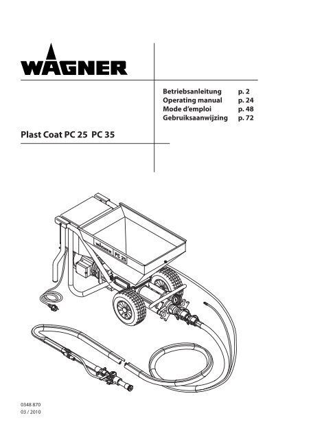
<strong>Plast</strong> <strong>Coat</strong> <strong>25</strong> · <strong>35</strong>DInhaltsverzeichnisInhaltsverzeichnis1 Sicherheitsvorschriften__________________ 42 Einführung in das Arbeiten mit deN Mörtelspritzmaschinen<strong>Plast</strong><strong>Coat</strong> <strong>25</strong> und <strong>35</strong>___ 52.1 Funktion der Mörtelspritzmaschinen<strong>Plast</strong><strong>Coat</strong> <strong>25</strong> und <strong>35</strong> _____________________________52.2 Verarbeitbare Beschichtungsstoffe_ ________________33 Technische Daten <strong>Plast</strong> <strong>Coat</strong> <strong>25</strong> und <strong>35</strong>_____ 54 Erklärungsbild MörtelspritzmaschineN<strong>Plast</strong><strong>Coat</strong> <strong>25</strong> und <strong>35</strong>_ _______________________ 64.1 Steuereinheit__________________________________74.1.1 Symbole am Drehrichtungsschalter________________74.2 Antrieb_ ______________________________________74.3 Behälter_ _____________________________________7Zubehör zum Behälter_ __________________________84.3.1 Schiebedeckel__________________________________84.3.2 Sackmangel____________________________________84.3.3 Container Ansaugsystem_ ________________________84.4 Kompressor (Zubehör)__________________________84.5 Mörtelschlauch mit elektrischer Fernbedienung _ __84.6 Spritzlanze mit Automatik_______________________94.7 Spritzlanze ohne Automatik_ ____________________95 Transport__________________________________ 95.1 Krantransport_ _________________________________96 Beschichtungsstoff-Ausrüstungstabelle<strong>Plast</strong> <strong>Coat</strong> <strong>25</strong> und <strong>35</strong>____________________ 10/117 Inbetriebnahme_ _______________________ 12-1412 Wartung_ _________________________________ 19Elektrische Ausrüstung_________________________ 19Längerer Nichtgebrauch________________________ 1913 ersatzteilliste plastcoat <strong>25</strong> und <strong>35</strong>_______ 20ersatzteilBild plastcoat <strong>25</strong> und <strong>35</strong>_______ 9714 Ersatzteilliste Spritzlanzemit Automatik_____________________________ 21Ersatzteilbild Spritzlanzemit Automatik_____________________________ 9815 Ersatzteilliste Spritzlanzeohne Automatik___________________________ 21Ersatzteilbild SpritzlanzeOhne Automatik___________________________ 9816 Ersatzteilliste und ErsatzteilbildKompressor V 400__________________________ 2217 Ersatzteilliste und ErsatzteilbildContainer Ansaugsystem_ ________________ 2318 Zubehör <strong>Plast</strong><strong>Coat</strong> <strong>25</strong> und <strong>35</strong> _ ____________ 24Zubehörbild <strong>Plast</strong><strong>Coat</strong> <strong>25</strong> und <strong>35</strong> _____ 99/100<strong>WAGNER</strong>-Servicenetz_______________________________ <strong>25</strong>Prüfung der Mörtelspritzmaschine___________________ 101Wichtiger Hinweis zur Produkthaftung________________ 101Garantieerklärung_ ____________________________101/102Konformitätserklärung_________________________ 1098 Allgemeine Hinweise ZurAnwendungstechnik______________________ 149 Montage von Zubehör_________________ 15/169.1 Kompressor__________________________________ 159.2 Sackmangel__________________________________ 15Verarbeitung von Beschichtungsstoffenin Säcken____________________________________ 169.3 Container Ansaugsystem_ ______________________ 1610 AuSSerbetriebnahme und Reinigung_ __ 16/1710.1 Mörtelschlauch reinigen________________________ 1610.2 Gerätereinigung und Pumpenmantel Austauschen__ 1710.3 Spritzlanze reinigen_ __________________________ 1711 Behebung von Störungen______________ 18/193
<strong>Plast</strong> <strong>Coat</strong> <strong>25</strong> · <strong>35</strong>DEinführung in das Arbeiten mit der mörtelpsritzmaschine / Technische Daten2 Einführung in dasArbeiten mit derMörtelspritzmaschinen<strong>Plast</strong><strong>Coat</strong> <strong>25</strong> und <strong>35</strong>Die Mörtelspritzmaschinen können mit Durchlauf-, Fall-,Zwangs- oder Tellermischern zur Verarbeitung von mineralischenBeschichtungsstoffen kombiniert werden.In Verbindung mit dem Container Ansaugsystem (Zubehör)kann direkt vom Container abgesaugt werden.2.1 Funktion der Mörtelspritzmaschinen<strong>Plast</strong><strong>Coat</strong> <strong>25</strong> und <strong>35</strong>Zufuhr des Beschichtungsstoffes erfolgt über den Behälter.Die Zuführwendel fördert den Beschichtungsstoff zur Exzenter-Schneckenpumpe.Diese Pumpe baut den zum Transportdurch den Mörtelschlauch notwendigen Druck auf. An derSpritzlanze wird die zur Zerstäubung notwendige Druckluftzugeführt.Über die elektrische Fernbedienung ist die Mörtelspritzmaschineein- und ausschaltbar.Mit der stufenlos einstellbaren Fördermenge des Beschichtungsstoffsist ein weiches, gleichmäßiges Spritzbild erzielbar.2.2 Verarbeitbare Beschichtungsstoffe• Wärmedämm-Verbundsysteme-Kleber(Mineralische- und Kunstharzsysteme)• Kunstharzputze bis Korngröße 5 mm• Silikatputze bis K 5• Silikonharzputze bis K 5• Mineralische Oberputze bis K 5• Leichtputz-Systeme bis K 5• Kratzputz bis K 5• Dämmputze• Sanierputze• Porenbetonbeschichtung• Quarzplastik• Dachbeschichtungen• Flammschutzbeschichtungen• Mineralische Dichtungsschlämme• Bitumenemulsionen• Armierungsspachtel• Flüssige Rauhfaser• Zargenverguss-Mörtel• Kunstharz-Putzgrund• Haftgrundierung• Füllfarben auch faserhaltig• Elastikbeschichtung• Akustikputz kunstharzgebunden• Spachtelmassen kunstharzgebunden• BetonspachtelAlle Beschichtungsstoffe müssen zur Maschinenverarbeitunggeeignet sein. Siehe Produktdatenblatt des zu verarbeitendenBeschichtungsstoffs.Verwendung anderer Beschichtungsstoffe nur nach Rücksprachemit dem Hersteller oder der <strong>WAGNER</strong> Anwendungstechnik.3 Technische Daten<strong>Plast</strong><strong>Coat</strong> <strong>25</strong> <strong>Plast</strong><strong>Coat</strong> <strong>35</strong>Spannung: 230 V ~, 50 Hz 400 V, 50 Hz V3 ~Absicherung:16 A trägeGeräteanschlussleitung6 m lang: 3 x 2,5 mm 2 5 x 1,5 mm 2Motorleistung P 1: 2,2 kW 3,6 kWMax. Fördermenge (Wasser):Pumpe gelb:Pumpe braun:Pumpe grün:Max. Betriebsdruck:Max. Korngröße:Abmessungen L x B x H:Behälterinhalt:10 l/min15 l/min20 l/min15 l/min20 l/min<strong>25</strong> l/min40 barK5 mm1200 x 520 x 660 mm60 lGewicht: 85 kg 87 kgReifendruck max:2 barSchutzart: IP 54Max. Schalldruckpegel:77 dB (A)*Zerstäuberluftanschluss:Schnellkupplung DN 7 mmMax. Zerstäuberluftdruck:10 barBenötigte Druckluftmenge220 l/minmindestens:Strukturdüse:8 mm (Standard)Mörtelschlauch:DN 27 mm, 10 m (Standard)* Messort: Abstand 1 m seitlich vom Gerät und 1,60 müber schallhartem Boden.5
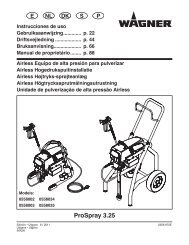
D<strong>Plast</strong> <strong>Coat</strong> <strong>25</strong> · <strong>35</strong>Erklärungsbild4 Erklärungsbild Mörtelspritzmaschinen <strong>Plast</strong><strong>Coat</strong> <strong>25</strong> und <strong>35</strong>1 Steuereinheit2 Behälter3 Zuführwendel4 Pumpenmantel – Pumpenschnecke5 Manometer6 Auslaufeinheit7 Druckluft-Anschluss8 Mörtelschlauch komplett9 Strukturdüse10 Spritzlanze mit Automatik111 Schalthülse, Ein- und Ausschalten der Mörtelspritzmaschineüber Fernbedienung12 Spritzlanze ohne Automatik13 Fernbedienungsschalter, Ein- und Ausschalten der Mörtelspritzmaschineüber Fernbedienung14 Elektromotor mit Getriebe15 Bügel zur Aufwicklung der Geräteanschlussleitung16 Anschluss für Fernbedienung17 Sicherheitsgitter23171615457146131291110986
<strong>Plast</strong> <strong>Coat</strong> <strong>25</strong> · <strong>35</strong>DSteuereinheit4.1 Steuereinheit1 Hauptschalter 0–12 Kontrollleuchte3 Fördermengenregler 0–104 Drehrichtungsschalter5 Geräteanschlussleitung6 Anschluss für Fernbedienung64.1.1 Symbole am Drehrichtungsschalter(Abb. 4)1 Druckentlastung oder Pumpenmantel aufziehen, Pumpeläuft rückwärts.2 „0“ Antrieb ausgeschaltet.3 „AUTO.“ Fernbedienung über die Spritzlanze.4 Spritzen oder Pumpenmantel abziehen. Pumpe läuft vorwärts.2 3OAUTO.21 431Mit dem Hauptschalter (1, Abb. 3) ist die Mörtelspritz maschineeinschaltbar.Die Kontrollleuchte (2) zeigt die Betriebsbereitschaft an.Mit dem Fördermengenregler (3) ist die Fördermenge stufenloseinstellbar.544.2 AntriebBei Überlastung schaltet sich die Mörtelspritzmaschine ab.Hauptschalter (1, Abb. 3) und Drehrichtungsschalter (4, Abb.3) auf „0“ stellen. Mindestens 10 Sekunden warten, dann Mörtelspritzmaschinewieder einschalten.4.3 Behälter (Abb. 5)1 Behälter aus Edelstahl mit Gitter.Inhalt: 60 Liter17
D<strong>Plast</strong> <strong>Coat</strong> <strong>25</strong> · <strong>35</strong>Zubehör zum behälterZubehör zum Behälter4.3.1 SchiebedeckelVerhindert Verschmutzung des Beschichtungsstoffs.Verlängert die Aushärtezeit des Beschichtungsstoffs besondersbei Sonneneinstrahlung.4.3.2 SackmangelZur Verarbeitung von Beschichtungsstoff in Säcken, kann aufden Schiebedeckel eine Sackmangel aufgesetzt werden.4.5 Mörtelschlauch mit elektrischerFernbedienung (Abb. 7)1 Materialanschluss-Mörtelspritzmaschine2 Fernbedienungsanschluss-Mörtelspritzmaschine3 Zerstäuberluftanschluss-Druckluftversorgung4 Materialanschluss-Spritzlanze5 Mörtelschlauch6 Zerstäuberluftanschluss-Spritzlanze7 Fernbedienungsanschluss – Spritzlanze oder Fernbedienungsschalter1234.3.3 Container AnsaugsystemZum Absaugen von Beschichtungsstoff aus einem Container,kann statt des Behälters ein Container Ansaugsystem eingesetztwerden.4.4 Kompressor (Zubehör)V 400 Ansaugvolumen 360 l/min (Abb. 6)1 Kompressoraufnahme2 DruckluftanschlussHinweis:Kompressor nur nach der beigefügten Betriebsanleitung betreiben.7 6 5 4218
<strong>Plast</strong> <strong>Coat</strong> <strong>25</strong> · <strong>35</strong>DTransport4.6 Spritzlanze mit Automatik (Abb. 8)1 Materialanschluss2 Schalthülse, Ein- und Ausschalten der Mörtelspritzmaschineüber Fernbedienung3 Strukturdüse4 Lufthahn5 Materialhahn6 Fernbedienungsanschluss7 Zerstäuberluftanschluss1In die Spritzlanze sind verschiedene Strukturdüsen einsetzbar,siehe Zubehör Seite 24, Pos. 1.Die Düsengröße richtet sich nach der Korngröße desBeschichtungsstoffs und dem gewünschten Spritzbild.5 Transport• Mörtelspritzmaschine fahren:An den Klappgriffen (1, Abb. 10) anfassen, anheben und fahren.• Mörtelspritzmaschine tragen:An den Klappgriffen (1) und am Frontbügel (2) anfassen undanheben.2<strong>35</strong>.1 KrantransportAnhängepunkte für die Bänder oder Seile (keine Drahtseile)siehe Abbildung 10.7 6 5 4In die Spritzlanze sind verschiedene Strukturdüsen einsetzbar,siehe Zubehör Seite 24, Pos. 1.Die Düsengröße richtet sich nach der Korngröße des Beschichtungsstoffsund dem gewünschten Spritzbild.4.7 Spritzlanze ohne Automatik (Abb. 9)1 Zerstäuberluftanschluss2 Lufthahn3 Strukturdüse4 Materialhahn5 Materialanschluss21215 4 39
D<strong>Plast</strong> <strong>Coat</strong> <strong>25</strong> · <strong>35</strong>Beschichtungsstoff-AusrüstungstabelleMörtelschläuche6 Beschichtungsstoff-Ausrüstungstabelle<strong>Plast</strong><strong>Coat</strong> <strong>25</strong> und <strong>Plast</strong><strong>Coat</strong> <strong>35</strong>Legende: bis 30 m Förderradius ● erforderliches Zubehör✶ bis 50 m Förderradius empfohlenes ZubehörRW RührwerkT<strong>25</strong> K DurchlaufmischerZM ZwangsmischerBestell-Nr.BezeichnungKH-Streichputz/BetonkontaktKH-Grundplastik/QuarzplastikRauhfaserfarbeKunstharzgebundene Systeme0348 . . . <strong>Plast</strong><strong>Coat</strong> <strong>25</strong>, 230 V~, 50 Hz ✶ ✶ ✶ ✶ 0348 . . . <strong>Plast</strong><strong>Coat</strong> <strong>35</strong>, 400 V, 50 Hz, V3~ ✶ ✶ ✶ ✶ ✶ ✶ ✶ ✶ ✶ ✶0348 946 Mörtelschlauch DN <strong>35</strong> – 13,3 m x Stück 1 1 1 1 1 1 10348 912 Mörtelschlauch DN 27 – 10 m x Stück 4 3 4 3 2 4 4 2 3 3 3 30348 909 Mörtelschlauch DN 19 – 10 m x Stück 1 1 1 1 1 1 10342 <strong>25</strong>5 Mörtelschlauch DN 19 – 2 m Poren-Beton BeschichtungKH-Glätt- u. StrukturspachtelQuarzhaltige MineralfarbenKH-Roll- und SpachtelputzKH-ArmierungsspachtelKH-Rillenputz bis K 5KH-Kratzputz bis K 5Silikatputz bis K 5Silikonharzputz bis K 5Spritzlanzen und DüsenPumpenZubehör0348 2410342 200Spritzlanze mit AutomatikSpritzlanze ohne Automatik● ● ● ● ● ● ● ● ● ● ● ●0348 960 Deckenspritzlanze mit Automatik 0342 912 Unterputzlanze 200 U0342 246 Auftragspistole0268 779 Strukturdüse 4 4 40348 915 Strukturdüse 5 5 5 5 5 50268 780 Strukturdüse 6 6 6 6 6 6 6 60348 916 Strukturdüse 7 7 7 7 7 7 7 7 7 70268 781 Strukturdüse 8 8 8 8 8 8 8 8 8 80348 917 Strukturdüse 9 9 9 9 9 90268 782 Strukturdüse 10 10 10 10 100342 327 Strukturdüse 12 12 12 12 120268 905 Strukturdüsensatz 4 6 8 10 0268 726 Unterputzdüsensatz 14 16 180348 3150348 3160348 9<strong>25</strong>0348 9260348 9270348 928Pumpenmantel gelb (Standard)Pumpenschnecke gelb (Standard)Pumpenmantel braun (Zubehör)Pumpenschnecke braun (Zubehör)Pumpenmantel grün, nachspannbar (Zubehör)Pumpenschnecke grün (Zubehör)● ● ● ● ● ● ● ● ● ● ● ●0342 231 Kompressor V 400, Ansaugvolumen 360 l/min, 230 V~, 50 Hz ● ● 500l ● 500l ● ● ● ● ● ● ●0348 963 Sackmangel (Schiebedeckel 0348 962 erforderlich) ●0348 907 Container-Ansaugsystem0343 002 Durchlaufmischer <strong>WAGNER</strong> T <strong>25</strong> K RW RW RW RW RW RW RW RW RW RW RW RWZubehörbild, siehe Seite 99/100.10
<strong>Plast</strong> <strong>Coat</strong> <strong>25</strong> · <strong>35</strong>DBeschichtungsstoff-ausrüstungstabelleMineralische PutzsystemeWDVS-Kleber/SpachtelArmierungs-FaserspachtelRillenputz bis K 5Leicht-UnterputzLeicht-StrukturputzKalk-InnenputzZement-SockelputzKalk-Zement-GrundputzDämmputzSanierputzAkustikputzSchlitzmauermörtelFlammschutzmörtelMineral-Edelkratzputz<strong>PC</strong>C-Fein-/Lunkerspachtel<strong>PC</strong>C-Dicht-/Elastikschlämme<strong>PC</strong>C-Saniermörtel bis K 4Quarzhaltige ElastikschlämmeFlammschutzbeschichtungDachbeschichtungBitumenabdichtungSpezialanwendungen ✶ ✶ ✶✶ ✶ ✶ ✶ ✶ ✶ ✶ ✶2 2 2 2 2 1 1 1 1 2 2 3 22 2 2 2 2 2 2 2 2 1 3 1 2 3 3 1 3 31 1 1 1 ● ● ● ● ● ● ● ● ●● ● ● ● ● ● ● ● ● ●4Auskunft auf Anfrage eventuell Test erforderlich5 5 56 6 6 6 67 7 7 7 78 8 8 8 8 8 8 89 9 9 9 9 910 10 10 10 10 1012 12 12 16 16 16 18 18 14● ● ● ● ● ● ● ●● ● ● ● ● ● ● ● ● ● ●● ● ● ● ● ● ● ● ● ● 500l ● ● ● ● ● ● ● 500 lAuskunft auf Anfrage eventuell Test erforderlichAuskunft auf Anfrage eventuell Test erforderlichZur Verarbeitung von Beschichtungsstoffen aus dem Container.T<strong>25</strong>K T<strong>25</strong>K T<strong>25</strong>K T<strong>25</strong>K T<strong>25</strong>K T<strong>25</strong>K T<strong>25</strong>K T<strong>25</strong>K T<strong>25</strong>K T<strong>25</strong>K T<strong>25</strong>K T<strong>25</strong>K T<strong>25</strong>K T<strong>25</strong>K ZM RW ZM RW RWVerwendung anderer Beschichtungsstoffe nur nach Rücksprache mit der <strong>WAGNER</strong>-Anwendungstechnik.11
D<strong>Plast</strong> <strong>Coat</strong> <strong>25</strong> · <strong>35</strong>DInbetriebnahme7 InbetriebnahmeAufstellortMörtelspritzmaschine eben aufstellen, um ein Wegrutschenzu vermeiden.Kompressor (Zubehör)Kompressoraufnahme an der Mörtelspritzmaschine einhängen.Kompressor aufsetzen, festschrauben und an das Stromnetzanschließen.Mörtelschlauch anschließen• Auslaufeinheit (1, Abb. 11) auf festen Sitz überprüfen.Gegebenenfalls Sterngriffe (2) von Hand nachziehen.• Mörtelschlauch (3) anschließen und mit Spannhebeln (4) sichern.• Fernbedienung am Anschluss (5) an der Steuereinheit anschrauben.• Zerstäuberluftanschluss (6) am Mörtelschlauch an dieDruckluft-Versorgung oder den Kompressor (Zubehör) ankuppeln.Spritzlanze mit Automatik anschließen• Strukturdüse (1, Abb. 12) mit Konus in Richtung Spritzkopfin die Spritzlanze montieren.Düsengröße sollte mindestens dreifache Korngröße betragen,z. B. Korngröße Kunstharzputz –> 3 mmdüsengröße –> 10 mm• Spritzlanze (2) anschließen und mit Spannhebeln (3) sichern.• Materialhahn (4) schließen.• Kupplungsstecker (5) für Fernbedienung am Steuerkabeldes Mörtelschlauchs anschrauben.• Zerstäuberluftanschluss (6) am Luftschlauch des Mörtelschlauchsankuppeln.32156 5 421Spritzlanze ohne Automatik anschließen• Fernbedienungsschalter (1, Abb. 13) mit beiden O-Ringen(2) am Mörtelschlauch befestigen.• Kupplungsstecker (3) für Fernbedienung am Steuerkabeldes Mörtelschlauchs anschrauben.• Strukturdüse (4) mit Konus in Richtung Spritzkopf in dieSpritzlanze montieren.Düsengröße sollte mindestens dreifache Korngröße betragen,z. B. Korngröße Kunstharzputze –> 3 mmdüsengröße –> 10 mm• Spritzlanze (5) anschließen und mit Spannhebeln (6) sichern.• Materialhahn (7) schließen.• Zerstäuberluftanschluss (8) am Luftschlauch des Mörtelschlauchsankuppeln.64312
<strong>Plast</strong> <strong>Coat</strong> <strong>25</strong> · <strong>35</strong>DInbetriebnahme 85 7Empfohlene Gleitmittel für den MörtelschlauchWasser reicht als Gleitmittel nicht aus.Verstopfungs-Gefahr!Kunstharz Produkte –> Kunstharz Dispersion<strong>PC</strong>C-Systeme –> Zellulosekleister321 6Verlängerungsleitung <strong>Plast</strong><strong>Coat</strong> <strong>25</strong>Leitungsquerschnitt min. 3 x 2,5 mm 2Verlängerungsleitung ganz abrollen.Auf einwandfreie Kupplungsstücke und Steckerachten.Verlängerungsleitung <strong>Plast</strong><strong>Coat</strong> <strong>35</strong>Leitungsquerschnitt min. 5 x 2,5 mm 2Verlängerungsleitung ganz abrollen.Auf einwandfreie Kupplungsstücke und Steckerachten.Geräteanschlussleitung so auslegen, daß keineStolpergefahr besteht.Vor Beschädigungen, z.B. durch Überfahren,schützen.4• 2–3 l Kunstharz-Dispersion oder Zellulosekleister in den Behältereinfüllen.• Achtung: Drehrichtungsschalter (4, Abb. 14) auf „0“ stellenvor einschalten des Hauptschalters (1, Abb. 14).Pumpe läuft bereits bei Fördermengenregler-Stellung„0“.• Hauptschalter (1, Abb. 14) auf „1“ stellen. Kontrollleuchte (2)zeigt Betriebsbereitschaft an.• Fördermengenregler (3) auf „5“ stellen.• Drehrichtungsschalter (4) auf „AUTO.“ (Fernbedienung überSpritzlanze) stellen.• Spritzlanze über leeren Eimer halten.2• Vor Anschluss an das Stromnetz darauf achten, daß dieNetzspannung mit der Angabe auf dem Leistungsschildübereinstimmt.• Anschluss an das Stromnetz nur über einen besonderenSpeisepunkt z.B. über einen Baustromverteiler mit Fehlerstromschutzeinrichtungmit INF ≤ 30 mA.• Mörtelspritzmaschine ans Stromnetz anschließen.Mörtelspritzmaschine vorbereitenNur mit eingesetztem Sicherheitsgitter arbeiten.1Spritzlanze mit Automatik• Materialhahn (3, Abb. 15) an der Spritzlanze öffnen.Mörtelspritzmaschine wird eingeschaltet.Spritzlanze ohne Automatik• Materialhahn (3, Abb. 16) an der Spritzlanze öffnen.Fernbedienungsschalter (1, Abb. 16) drücken.Mörtelspritzmaschine wird eingeschaltet.Spritzlanze mit Automatik• Wenn Kunstharz-Dispersion oder Zellulosekleister in denMörtelschlauch eingepumpt ist – Gerät ausschalten, Schalthülse(1, Abb. 15) um 90° im Uhrzeigersinn auf Anschlag drehen.• Materialhahn (3, Abb. 15) schließen.3413
D<strong>Plast</strong> <strong>Coat</strong> <strong>25</strong> · <strong>35</strong>allgemeine Hinweise zur AnwendungstechnikSpritzlanze ohne Automatik• Wenn Kunstharz-Dispersion oder Zellulosekleister in denMörtelschlauch eingepumpt ist – Gerät mit dem Fernbedienungsschalter(1, Abb. 16) ausschalten.• Materialhahn (3, Abb. 16) schließen.• Viskosität des Beschichtungsstoffs prüfen.• Beschichtungsstoff in den Behälter einfüllen. Bei mineralischemBeschichtungsstoff Behälter nur halb füllen.Spritzlanze mit Automatik• Lufthahn (2, Abb. 15) schließen.Spritzlanze ohne Automatik• Fernbedienungsschalter (1, Abb. 16) am Mörtelschlauchdrücken.• 3–5 Sekunden warten.• Materialhahn (3, Abb. 16) schließen.Nichtbeachtung führt zu vorzeitigem Verschleißdes Materialhahns.• Materialhahn (3, Abb. 15) öffnen.• Beschichtungsstoff wird in den Mörtelschlauch gepumpt.Spritzlanze ohne Automatik• Materialhahn (3, Abb. 16) öffnen.• Gerät mit Fernbedienungsschalter (1, Abb. 16) einschalten.• Beschichtungsstoff wird in den Mörtelschlauch gepumpt.• Kunstharz-Dispersion oder Zellulosekleister aus dem Mörtelschlauchin einen Eimer pumpen.• Sobald nur noch Beschichtungsstoff aus der Spritzlanzeaustritt – Gerät über Fernbedienung ausschalten und Materialhahnan der Spritzlanze schließen.• Spritzlanze über den Behälter halten.• Materialhahn (3, Abb. 15 und 16) öffnen und Gerät überFernbedienung einschalten.• Gewünschte Fördermenge am Fördermengenregler (3, Abb.3, Seite 7) einstellen.• Gerät über Fernbedienung ausschalten und Materialhahn(3, Abb. 15 und 16) schließen.• Mörtelschlauch mit Schlauchhalter am Gerüst befestigen(jeden Verbindungsschlauch einzeln).Mörtelschlauch nicht knicken!Vor Beschädigungen, z.B. Überfahren sowievor spitzen Gegenständen und Kantenschützen.Beginn des Spritzvorgangs• Lufthahn (2, Abb. 16) schließen.Spritzlanze mit Automatik (Abb. 15)13 2Spritzlanze ohne Automatik (Abb. 16)2• Lufthahn (2, Abb. 15 und 16) und Materialhahn (3, Abb. 15und 16) an der Spritzlanze öffnen.Spritzlanze ohne AutomatikGerät über Fernbedienungsschalter (1, Abb. 16) einschalten.Ende des SpritzvorgangsSpritzlanze mit Automatik• Schalthülse (1, Abb. 15) um 90° im Uhrzeigersinn auf Anschlagdrehen.• 3–5 Sekunden warten.• Materialhahn (3, Abb. 15) schließen.Nichtbeachtung führt zu vorzeitigem Verschleißdes Materialhahns.8 Allgemeine Hinweise ZurAnwendungstechnikSpritztechnik1 3Während des Spritzens die Spritzlanze in gleichmäßigem Abstand30 – 60 cm zum Objekt führen. Bei Nichteinhaltung stelltsich ein unregelmäßiges Spritzbild ein.Das Spritzbild ist abhängig vom Beschichtungsstoff, Viskosität,Düsengröße, Fördermenge und Zerstäuberluftmenge.14
<strong>Plast</strong> <strong>Coat</strong> <strong>25</strong> · <strong>35</strong>DMontage von zubehörBeispiele:Feine Struktur––> große ZerstäuberluftmengeGrobe Struktur––> kleine ZerstäuberluftmengeGrößere Fördermenge ––> größere ZerstäuberluftmengeDie gewünschte Struktur auf einer Musterfläche testen.Die seitliche Abgrenzung des Spritzstrahls soll nicht zu scharfsein, deshalb sollte der Abstand zwischen Spritzlanze und Objektentsprechend gewählt werden.Der Spitzrand soll allmählich auflockern, damit beim anschließendenDurchgang leicht überlappt werden kann.Wird die Spritzlanze immer parallel und im Winkel von 90° zumObjekt geführt, so entsteht am wenigsten Spritznebel.Hinweis:Scharfkantige Körner und Pigmente führen zu hohem Verschleißvon Pumpe, Mörtelschlauch, Materialhahn und Düse.9 Montage von Zubehör9.1 KompressorV 400 Ansaugvolumen 360 l/min• Kompressoraufnahme (1, Abb. 17) einhängen und mit Sterngriff(2) festschrauben.• Kompressor aufsetzen. Halteblech (3) über die Kompressorfüßeschieben.• Mit den Sterngriffen (4) den Kompressor festschrauben.29.2 SackmangelSicherheitshinweisTechnische DatenWalzenlänge: 465 mmWalzendurchmesser: 66 mmGewicht: 6,7 kgQuetschgefahr!Nicht mit den Händen unter die Walzefassen.Inbetriebnahme der Sackmangel• Kurbel (1, Abb. 18) aufstecken und mit Klappstecker sichern.• Sackmangel zusammen mit Schiebedeckel (2, Zubehör) einsetzen.• Sterngriffschrauben (3) etwa 2 cm herausdrehen.• Sackmangel mit Kurbel (1) nach rechts von vorn auf denSchiebedeckel auffahren. Führungsrollen (4) über die Anschlagbolzenan der Schiebedeckel-Unterseite bewegen.• Anpressdruck der Walze (5) einstellen. Sterngriffschrauben(3) bis auf Anschlag nach rechts drehen.• Kurbel drehen und Sackmangel ganz nach hinten fahren.2<strong>35</strong>1434115
D<strong>Plast</strong> <strong>Coat</strong> <strong>25</strong> · <strong>35</strong>ausserbetriebnahme und reinigungVerarbeiten von Beschichtungsstoffen in Säcken• Schiebedeckel etwa 15 cm zurückziehen.• Sack so auf den Schiebedeckel legen, dass die Oberseite inRichtung vorderes Schiebedeckelende zeigt.• Sack aufschneiden.• Beschichtungsstoff in den Behälter fließen lassen.• Sackmangel durch Drehen der Kurbel nach vorn über denSack fahren, bis die Führungsrollen an den Anschlagbolzenanstehen.• Auspressvorgang erleichtern – Sackmangel mit der linkenHand am Gestell der Sackmangel führen.• Restlichen Beschichtungsstoff mit Spachtel aus derSacköffnung abstreifen.9.3 Container Ansaugsystem215• Gerät mit Hauptschalter ausschalten• Netzstecker aus der Steckdose ziehen und gegen unbeabsichtigtesWiedereinstecken sichern.• Am Behälter (1, Abb. 19) die Sechskantmuttern (2) abschrauben,Scheiben entfernen.• Behälter abnehmen.• Containeranschluss (3) auf das Behälterunterteil aufsetzen.Scheiben auflegen und mit den Sechskantmuttern (2) festschrauben.• Ansaugschlauch (5) am Containeranschluss (3) anschließenoder Anschlussbogen (6) an Containeranschluss (3) montierenund dort den Ansaugschlauch (5) anschließen.• Ansaugschlauch mit Wasser füllen und an den Container anschließen.• Mörtelspritzmaschine einschalten.263Hinweis:Alle Anschlüsse müssen luftdicht schließen, damit sich ein Vakuumaufbauen kann.Auftragen von etwas Maschinenfett auf die Gummidichtungender Anschlüsse erleichtert das Auf- und Zudrehen.10 AuSSerbetriebnahme undReinigungMotor und Steuereinheit der Mörtelspritzmaschinenicht mit Wasserstrahl,Hochdruck- oder Dampfhochdruckreinigerabspritzen. Kurzschlussgefahr durcheindringendes Wasser.10.1 Mörtelschlauch reinigen• Behälter leer pumpen.Bei Betrieb mit dem Container Ansaugsystem, Ansaugschlauchvom Container trennen.Wichtig: Mörtelspritzmaschine nicht trocken laufen lassen.• Strukturdüse aus der Spritzlanze entfernen und reinigen.Mörtelschlauch muss drucklos sein.Eventuell Drehrichtungsschalter kurz auf(rückwärts) stellen.Manometer beachten ––> 0 bar.Schutzbrille tragen.16
<strong>Plast</strong> <strong>Coat</strong> <strong>25</strong> · <strong>35</strong>Dausserbetriebnahme und reinigung• Mörtelschlauch von der Auslaufeinheit abkuppeln.• Reinigungskugel in Mörtelschlauch einstecken. Mörtelschlauchwieder anschließen.• Wasser in den Behälter einfüllen.Bei Betrieb mit dem Container Ansaugsystem, Ansaugschlauchin Behälter mit Wasser eintauchen.Mörtelspritzmaschine einschalten.• Nach wenigen Sekunden tritt die Reinigungskugel aus derSpritzlanze aus.• Je nach verarbeitetem Beschichtungsstoff, Reinigungsvorgang3 – 4 mal wiederholen.Weitere Reinigungsmöglichkeit besteht mit dem Reinigungsadapter.Dieser Reinigungsadapter ist an einen Wasserschlauch oderWasserhahn mit der Klauenkupplung anschließbar.Reinigungskugel in den Mörtelschlauch einstecken Mörtelschlauchan den Reinigungsadapter ankuppeln und mit Wasserdurchspülen.• Containeranschluss vom Behälterunterteil abschraubenund abnehmen.• Behälterunterteil, Containeranschluss und Ansaugschlauchmit Wasserstrahl und falls notwendig mit geeigneter Bürstereinigen.• Pumpenschnecke und Pumpenmantel gründlich mit Wasserreinigen.• Auslaufeinheit (2) innen mit Flachbürste reinigen.• Gewinde für die Sterngriffe sauber halten und einölen.10.2 Gerätereinigung und PumpenmantelAustauschenBei allen Reinigungsarbeiten das Sicherheitsgitternie entfernen!Demontage• Pumpe schmieren.Drehrichtungsschalter auf(rückwärts) stellen.Pumpengleitmittel oder etwas Geschirrspülmittel in dieAuslaufeinheit (2, Abb. 20) sprühen oder etwas Geschirrspülmittelin den Behälter geben und durch die Pumpe fördern.• Drehrichtungsschalter auf „0“ stellen.• Sterngriffe (1, Abb. 20) abschrauben.• Auslaufeinheit (2) nach vorne abnehmen.• Fördermengenregler auf „3“ stellen.• Drehrichtungsschalter auf(vorwärts) stellen.Montage PumpenmantelWichtig:Pumpenschnecke und Pumpenmantel mit Pumpengleitmitteleinsprühen oder mit Geschirrspülmittel benetzen.• Drehrichtungsschalter auf(rückwärts) stellen.Quetschgefahr3 4 1 2Quetschgefahr!• Pumpenmantel (3) schiebt sich von der Pumpenschnecke.• Drehrichtungsschalter auf „0“ stellen.• Behälter und Behälterunterteil mit Wasserstrahl reinigen.Bei Betrieb mit dem Container Ansaugsystem,Gerät mit Hauptschalter ausschalten,Netzstecker aus der Steckdose ziehenund gegen unbeabsichtigtes Wiedereinsteckensichern.• Pumpenmantel (3, Abb. 20) auf Pumpenschnecke führen.Hierbei muss die Leiste auf dem Pumpenmantel (3) in derRechteckaussparung des Pumpenabziehers (4) gleiten.• Pumpenmantel zieht sich auf die Pumpenschnecke auf.• Drehrichtungsschalter auf „0“ stellen.• Auslaufeinheit montieren.10.3 Spritzlanze reinigen• Strukturdüse reinigen.• Luftbohrungen in der Strukturdüse mit Reinigungsnadelreinigen.• Spritzlanze innen mit Flaschenbürste reinigen.17
D<strong>Plast</strong> <strong>Coat</strong> <strong>25</strong> · <strong>35</strong>Behebung von Störungen11 Behebung von StörungenStörung Mögliche Ursache BehebungMörtelspritzmaschineläuft nicht an.Mörtelspritzmaschine kannPumpenschnecke nicht durchdrehen.Mörtelspritzmaschine kannüber Fernbedienung nicht ein- /ausgeschaltet werden.Mörtelspritzmaschine baut imMörtelschlauch Druck auf.Es kommt jedoch kein Beschichtungsstoffan der Spritzlanze an.Mörtelspritzmaschine wurde überlastet.Pumpenschnecke sitzt im Pumpenmantelfest.Pumpe wurde nicht mit Pumpengleitmittelgeschmiert.Fernbedienung nicht eingeschaltet.Fernbedienleitung nicht angeschlossenoder defekt.Beschichtungsstoff-“stopfer“ im Mörtelschlauch.Mörtelschlauch nicht mitKunstharz-Dispersion oder Zellulosekleistervorgespült.Hauptschalter und Drehrichtungsschalter auf „0“stellen.Mörtelspritzmaschine nach etwa 10 Sekundenwieder einschalten.Achtung: Drehrichtungsschalter auf „0” stellenvor einschalten des Hauptschalters.Fördermengenregler auf „0“ und Drehrichtungsschalterauf(vorwärts) stellen.Sobald die Pumpenschnecke mit konstanterDrehzahl läuft, Fördermengenregler langsam aufdie gewünschte Fördermenge einstellen.Drehrichtungsschalter auf „AUTO.“ stellen.Fernbedienleitung anschließen,Kupplungsstellen prüfen, Fernbedienleitungauf Beschädigung prüfen.Durch Abtasten des Mörtelschlauchs Verstopfunglokalisieren. Mörtelschlauch entlasten – Drehrichtungsschalterauf(rückwärts) stellen.Beschichtungsstoff in den Behälter zurückpumpen.Mörtelschlauch muss drucklossein.Manometer beachten ––> 0 bar.Schutzbrille tragen.Beim Spritzen setzt der Spritzstrahlaus, „Spucken“ tritt ein.Während des Spritzens trittplötzlich kein Beschichtungsstoffmehr aus.Kein Beschichtungsstoff im Behälter.Pumpe hat Luft angesaugt.Beschichtungsstoff rutscht nicht imBehälter nach.Verstopfung der Strukturdüse durchVerunreinigung des Beschichtungsstoffsoder durch zu große Körnung.Mörtelschlauch abkuppeln – im verstopftenBereich von Hand knicken. Mörtelschlauchmit Wasserschlauch durchspülen. Hat sich dieVerstopfung gelöst, Kunstharz-Dispersion oderZellulosekleister in den Mörtelschlauch einfüllen.Mörtelschlauch wieder ankuppeln.Beschichtungsstoff einfüllen und umpumpen bisBeschichtungsstoff blasenfrei austritt.Achtung:Pumpe nicht trocken laufen lassen. Pumpeläuft heiß, dadurch „Stopfer“ Gefahr.Beschichtungsstoff nachfüllen.Mörtelspritzmaschine unbedingt ausschalten(siehe Sicherheitsvorschriften) – dann Beschichtungsstoffnachschieben.Mörtelspritzmaschine ausschalten.Materialhahn an der Spritzlanze schließen.Strukturdüse entfernen und reinigen.Eventuell größere Strukturdüse verwenden.Faustregel:Korngröße x 3 ––> Düsengröße18
<strong>Plast</strong> <strong>Coat</strong> <strong>25</strong> · <strong>35</strong>Dbehebung von störungen/ WartungStörung Mögliche Ursache BehebungKein sauberes, gleichmäßigesSpritzbild.Druck am Manometer steigtüber 40 bar an.Luftkanäle in der Strukturdüse sindteilweise mit Beschichtungsstoff verschlossen.Beschichtungsstoff hat zu hohe Viskosität.Mörtelspritzmaschine ausschalten.Materialhahn an der Spritzlanze schließen.Strukturdüse entfernen. Luftkanäle der Strukturdüsereinigen.Beschichtungsstoff verdünnen.Mörtelspritzmaschine fördertnicht genügend Beschichtungsstoff.Mörtelschlauch-Durchmesser zu gering.Mörtelschlauch zu lang.Fördermenge zu niedrig gewählt.Mörtelschlauchdurchmesser zu gering.Pumpenmantel verschlissen.Beschichtungsstoff hat zu hohe Viskosität.Zu kleine Strukturdüse.Mörtelschlauch mit größerem Durchmesser einsetzen.Kürzeren Mörtelschlauch einsetzen.Fördermengenregler höher einstellen.Mörtelschlauch mit größerem Durchmesser einsetzen.Neuen Pumpenmantel, bei Bedarf auch neuePumpenschnecke montieren.Achtung: Mit Pumpengleitmittel einsprühen.Beschichtungsstoff verdünnen.Größere Strukturdüse auswählenLiegt keine der genannten Störungsursachen vor, Defekt bei der <strong>WAGNER</strong>-Kundendienststelle beheben lassen.12 Wartung• Gewinde für die Sterngriffe sauberhalten und ölen.• Pumpenschnecke und Pumpenmantel mit Pumpengleitmitteleinsprühen.• Getriebemotor ist wartungsfrei.Elektrische AusrüstungLeitungen und Steckverbindungen prüfen. Mängel, wie loseVerbindungen, angeschmorte Leitungen oder verschmutzteund feuchte Steckverbindungen, sofort beseitigen.Arbeiten oder Reparaturen an der elektrischenAusrüstung nur von einer Elektrofachkraftdurchführen lassen.Auch dann, wenn Hinweise in der Betriebsanleitungsind. Für unsachgemäße Installationwird keine Haftung übernommen.Längerer NichtgebrauchBei Nichtgebrauch der Mörtelspritzmaschine über einen längerenZeitraum ist eine gründliche Reinigung und ein Schutzvor Korrosion erforderlich.19
D<strong>Plast</strong> <strong>Coat</strong> <strong>25</strong> · <strong>35</strong>ersatzteilliste plastcoat <strong>25</strong>/ <strong>35</strong>13 ersatzteilliste plastcoat <strong>25</strong> und <strong>35</strong> (Ersatzteilbild, siehe Seite 97)Pos. Bestell-Nr<strong>Plast</strong><strong>Coat</strong> <strong>25</strong>Bestell-Nr<strong>Plast</strong><strong>Coat</strong> <strong>35</strong>Benennung1 0348 363 0348 363 Motorkabel2 9982 820 9982 820 Kabelverschraubung3 9982 823 9982 823 Übergangsstück4 0348 230--------------------------0348 231Getriebemotor 230 V~, 50 HzGetriebemotor 400 V, 50 Hz, V3~5 9900 204 9900 204 Sechskantschraube M 8 x <strong>35</strong> DIN 931(2)6 9920 102 9920 102 Scheibe A 8,4 DIN 1<strong>25</strong>7 9900 1<strong>25</strong> 9900 1<strong>25</strong> Sechskantschraube M 8 x 50 DIN 9339 0348 334 0348 334 Stützscheibe10 9972 331 9972 331 Nutring 32 x 50 x 1011 0348 400 0348 400 Zwischenflansch12 9971 171 9971 171 O-Ring 90 x 3,514 9930 913 9930 913 Zylinderstift 8 x 4015 0348 324 0348 324 Schraube16 9921 518 9921 518 Federring B12 DIN 12717 0348 313 0348 313 Mitnehmerhülse18 9922 746 9922 746 Sprengring A 4519 0348 245 0348 245 Zuführwendel21 9900 511 9900 511 Senkschraube22 0348 307 0348 307 Behälter23 9900 109 9900 109 Sechskantschraube M 8 x <strong>25</strong> DIN 93324 0348 396--------------------------0348 397Typenschild <strong>PC</strong> <strong>25</strong>Typenschild <strong>PC</strong> <strong>35</strong><strong>25</strong> 9910 107 9910 107 Sechskantmutter M8 DIN 93426 2311 <strong>35</strong>6 2311 <strong>35</strong>6 Sicherheitsgitter27 0348 306 0348 306 Behälterunterteil30 9910 208 9910 208 Sechskantmutter M 8 DIN 98531 9900 118 9900 118 Sechskantschraube M 8 x 30 DIN 933Pos. Bestell-Nr<strong>Plast</strong><strong>Coat</strong> <strong>25</strong>Bestell-Nr<strong>Plast</strong><strong>Coat</strong> <strong>35</strong>Benennung32 0348 316 0348 316 Pumpenschneckegelb W 10/3 (Standard)33 0348 315 0348 315 Pumpenmantelgelb W 10/3 (Standard)34 9990 368 9990 368 Sterngriff M 16<strong>35</strong> 0342 321 0342 321 Adapter Fix-Nippel V <strong>35</strong>-M 2736 0348 233 0348 233 Auslaufeinheit37 9990 618 9990 618 Kupplung38 9970 109 9970 109 Dichtring39 9991 946 9991 946 Manometer40 9991 947 9991 947 Schutzkappe41 0348 349 0348 349 Rad42 9994 902 9994 902 Radkappe43 0348 419 0348 419 Wagengrundgestell44 9900 317 9900 317 Zylinderschraube M 8 x 50 DIN 91245 9990 863 9990 863 Rohrendkappe46 0348 318 0348 318 Deichselrohr rechts47 9920 103 9920 103 Scheibe A 6,4 DIN 1<strong>25</strong>48 9910 204 9910 204 Sechskantmutter M 6 DIN 98549 0348 347 0348 347 Deichselrohr links50 0348 422 ------------- ------------- 0348 424 GeräteanschlussleitungH07 RN-F3G2,5 – 6 mGeräteanschlussleitungH07 RN-F5G1,5 – 6 m51 9982 822 9982 822 Kabelverschraubung52 9951 063 9951 063 Sechskantmutter53 9951 078 9951 078 Sechskantmutter20
<strong>Plast</strong> <strong>Coat</strong> <strong>25</strong> · <strong>35</strong>DErsatzteilliste Spritzlanze14 Ersatzteilliste Spritzlanze mit Automatik(Ersatzteilbild siehe Seite 98)Pos.Bestell-Nr.Spritzlanze100 mm langBestell-Nr.Spritzlanze(Deckenspritzlanze)800 mm langBenennung0348 241 0348 960 Spritzlanze mit Automatik0348 904 0348 904 Verlängerungs-Set500 mm lang(Materialrohr undLuftrohr)0348 923 ------------- Verlängerungs-Set800 mm lang(Materialrohr undLuftrohr)1 9910 208 9910 208 Sechskantmutter M82 9920 102 9920 102 Scheibe 8,43 0348 243 0348 243 Hebel4 3051 679 3051 679 O-Ring <strong>35</strong> x <strong>25</strong> 0348 <strong>35</strong>4 ------------- Luftrohr 100 mm lang0348 921 0348 921 Luftrohr 800 mm lang0348 942 0348 942 Luftrohr 500 mm lang6 0348 <strong>35</strong>5 0348 <strong>35</strong>5 Düsenkopf7 0268 779 0268 779 Strukturdüse 40348 915 0348 915 Strukturdüse 50268 780 0268 780 Strukturdüse 60348 916 0348 916 Strukturdüse 70268 781 0268 781 Strukturdüse 8(Standard)0348 917 0348 917 Strukturdüse 90268 782 0268 782 Strukturdüse 100342 327 0342 327 Strukturdüse 12Pos.Bestell-Nr.Spritzlanze100 mm langBestell-Nr.Spritzlanze(Deckenspritzlanze)800 mm langBenennung8 0342 <strong>35</strong>0 0342 <strong>35</strong>0 Dichtscheibe9 0342 <strong>35</strong>1 0342 <strong>35</strong>1 Überwurfmutter10 0348 346 ------------ Materialrohr 100 mmlang0348 922 0348 922 Materialrohr 800 mmlang0348 943 0348 943 Materialrohr 500 mmlang11 9902 309 9902 309 Zylinderblechschraube4,2 x 1612 0348 460 0348 460 Abdeckung13 0348 216 0348 216 Kabel14 0348 244 0348 244 Anschlusshülse15 3105 540 3105 540 O-Ring 26 x 216 0348 461 0348 461 Anschlag17 9920 104 9920 104 Scheibe 4,318 0268 338 0268 338 Kugelhahn19 9983 237 9983 237 Doppelnippel 3/4 – 19983 238 9983 238 Doppelnippel 3/4 –Rundgewinde32 x 1/820 0342 313 0342 313 Fix-Nippel, AnschlussV 27*21 9991 112 9991 112 Kugelhahn*22 0268 604 0268 604 Luftschlauch**Loctite 22215 Ersatzteilliste Spritzlanze ohne Automatik(Ersatzteilbild siehe Seite 98)Pos.Bestell-Nr.Spritzlanze100 mm langBenennung0342 200 Spritzlanze ohne Automatik1 0268 779 Strukturdüse 40348 915 Strukturdüse 50268 780 Strukturdüse 60348 916 Strukturdüse 70268 781 Strukturdüse 8 (Standard)0348 917 Strukturdüse 90268 782 Strukturdüse 100342 327 Strukturdüse 122 0342 <strong>35</strong>0 DichtscheibePos.Bestell-Nr.Spritzlanze100 mm langBenennung3 0342 <strong>35</strong>1 Überwurfmutter4 0268 604 Luftschlauch*5 9991 112 Kugelhahn*6 0268 470 Düsenkopf7 0342 469 Materialrohr*8 9991 111 Kugelhahn9 9983 237 Doppelnippel 3/4 – 19983 238 Doppelnippel 3/4 – Rundgewinde32 x 1/810 0342 313 Fix-Nippel, Anschluss V 27** Loctite 22221
D<strong>Plast</strong> <strong>Coat</strong> <strong>25</strong> · <strong>35</strong>ersatzteilliste Kompressor16 ErsatzteillisteKompressor V 4001Pos. Bestell-Nr. Benennung1 0342 231 Kompressor V 400, 230 V~, 50 HzAnsaugvolumen 360 l/min2 9992 823 Schnellkupplung3 0348 452 Halteblech4 0348 442 Kompressoraufnahme5 9990 373 Sterngriff M 86 0348 957 Kompressoraufnahme<strong>25</strong>346522
<strong>Plast</strong> <strong>Coat</strong> <strong>25</strong> · <strong>35</strong>Dersatzteilliste container ansaugsystem17 Ersatzteilliste Container AnsaugsystemPos. Bestell-Nr. Benennung1 0348 907 Container Ansaugsystem2 9971 529 Dichtung3 0342 205 Ansaugschlauch4 0097 085 Kupplung5 0348 361 Anschlussplatte6 0348 947 Anschlussbogen7 0097 105 Kupplung2273716224<strong>25</strong>23
D<strong>Plast</strong> <strong>Coat</strong> <strong>25</strong> · <strong>35</strong>Zubehör <strong>Plast</strong>coat <strong>25</strong> und <strong>35</strong>18 Zubehör <strong>Plast</strong><strong>Coat</strong> <strong>25</strong> und <strong>35</strong> (zubehörbild siehe Seite 99/100)Pos. Bestell-Nr. Benennung1 0268 779 Strukturdüse 40348 915 Strukturdüse 50268 780 Strukturdüse 60348 916 Strukturdüse 70268 781 Strukturdüse 8 (Standard)0348 917 Strukturdüse 90268 782 Strukturdüse 100342 327 Strukturdüse 120268 905 Strukturdüsensatz 4, 6, 8, 102 0342 916 Reinigungsnadel3 0342 330 Reinigungskugel für DN 19 mm0342 331 Reinigungskugel für DN 27 mm0342 332 Reinigungskugel für DN <strong>35</strong> mm4 0342 329 Flaschenbürste zur Innenreinigungvon Auslaufeinheit und Spritzlanze5 9992 824 Pumpengleitmittel 500 ml6 0342 215 Schlauchhalter7 0342 241 Reinigungsadapter M 27 – GK0348 948 Reinigungsadapter M <strong>35</strong> – GK8 0348 9200342 321Adapter Fix-Nippel V 27 – M <strong>35</strong>Adapter Fix-Nippel V <strong>35</strong> – M 279 0348 946 Mörtelschlauch DN <strong>35</strong> – 13,3 m,Anschluss V <strong>35</strong> – M <strong>35</strong>0348 912 Mörtelschlauch DN 27 – 10 m,Anschluss V 27 – M 270348 930 Mörtelschlauch DN 19 – 20 m,Anschluss V 27 – Rundgewinde32 x 1/80348 909 Mörtelschlauch DN 19 – 10 m,Anschluss V 27 – Rundgewinde32 x 1/80342 <strong>25</strong>5 Mörtelschlauch DN 19 – 2 m,Anschluss V 27 – Rundgewinde32 x 1/810 9952 672 Stecker11 0342 314 Dichtung Fix-Kupplung M 279971 531 Dichtung Fix-Kupplung M <strong>35</strong>12 9952 673 Kupplung13 0268 216 Druckschalter zur Fernbedienungvon Spritzlanzen ohne AutomatikPos. Bestell-Nr. Benennung14 9983 238 Doppelnippel 3/4 – Rundgewinde32 x 1/815 0342 200 Spritzlanze 100 mm lang ohne Automatik16 0348 241 Spritzlanze 100 mm lang mit Automatik17 0348 961 Winkelspritzkopf 70° für Spritzlanzemit Automatik18 0348 904 Verlängerungs-Set 500 mm lang(Materialrohr und Luftrohr)für Spritzlanze mit Automatik0348 923 Verlängerungs-Set 800 mm lang(Materialrohr und Luftrohr) für Spritzlanzemit Automatik19 0348 960 Spritzlanze (Deckenspritzlanze)800 mm lang mit Automatik20 0342 285 Doppellanze400 mm lang mit Automatik21 0342 912 Unterputzlanze 200 U22 0268 726 Unterputzdüsensatz 14, 16, 1823 0342 240 Strukturspritzkopf für Auftragspistole24 0342 246 Auftragspistole, Anschluss V 27zum Auftragen von Wärmedämm –Verbundsysteme – Kleber<strong>25</strong> 0342 231 Kompressor V 400, 230 V~, 50 Hz,Ansaugvolumen 360 l/minohne Abschaltautomatik0342 906 Kompressor V 400, 230 V~, 50 Hz,Ansaugvolumen 360 l/minmit Abschaltautomatik26 0348 957 Kompressoraufnahme V 40029 0348 3160348 9260348 92830 0348 3150348 9<strong>25</strong>Pumpenschnecke gelb (Standard)Pumpenschnecke braunPumpenschnecke grünPumpenmantel gelb (Standard)Pumpenmantel braun31 0348 927 Pumpenmantel grün nachspannbar32 0348 907 Container Ansaugsystem33 0348 962 Schiebedeckel für Behälter34 0348 963 Sackmangel<strong>35</strong> 0348 958 Zubehörbox gefüllt mit diversem Zubehör24
<strong>Plast</strong> <strong>Coat</strong> <strong>25</strong> · <strong>35</strong>Dservicenetz in deutschlandServicenetz in DeutschlandBerlinJ. Wagner GmbHService-StützpunktFlottenstraße 28–4213407 BerlinTel. 0 30/ 41 10 93 86Telefax 0 30 / 41 10 93 87GrünstadtJ. Wagner GmbHService-StützpunktDieselstrasse 167269 GrünstadtTel. 0 63 59/ 87 27 55 0Telefax 0 63 59/ 80 74 80RatingenJ. Wagner GmbHService-StützpunktSiemensstraße 6-1040885 RatingenTel. 0 21 02 / 3 10 37Telefax 0 21 02 / 3 43 95StuttgartJ. Wagner GmbHService-StützpunktIn der Steige 6/17<strong>25</strong>64 NeckartenzlingenTel. 0 71 27 / 30 74Telefax 0 71 27 / 30 75MünchenJahnke GmbHHochstraße 782024 TaufkirchenTel. 0 89 /6 14 00 22Telefax 0 89 / 6 14 04 33email: info@airless.dewww.airless.deNürnbergGrimmer GmbHStarenweg 2891126 SchwabachTel. 0 91 22 / 7 94 73Telefax 0 91 22 / 7 94 75 0email: info@grimmer-sc.dewww.grimmer-sc.deMarkdorf – zentraleJ. <strong>WAGNER</strong> GmbHOtto-Lilienthal-Straße 1888677 MarkdorfPostfach 11 2088669 MarkdorfTel. 0 75 44 / 505-0Telefax 0 75 44 / 505-200www.wagner-group.comkundenzentrumTel. 0 75 44 / 505-664Telefax 0 75 44 / 505-155email: kundenzentrum@wagner-group.comtechnischer ServiceGünter ZimmerTel. 0 75 44 / 505-548Bernd DambacherTel. 0 75 44 / 505-563Heidersdorf in SachsenJ. Wagner GmbHService-StützpunktOlbernhauer Straße 1109526 HeidersdorfTel. 03 73 61 / 1 57 07Telefax 03 73 61 / 1 57 08WAGNeR kONtAktNetz deutSCHlANd, IM INteRNet zu FINdeN uNteR: WWW.WAGNeR-GROuP.COM/PROFI<strong>25</strong>
GB<strong>Plast</strong> <strong>Coat</strong> <strong>25</strong> · <strong>35</strong>Warning!Suction pumps develop high spraying pressures.Attention − Danger of injury!1Never reach into the spray jet with your fingers or hand!Never aim the spray lance at yourself or other persons!The materials sprayed cause chemical burns or irritations!Protect your skin and eyes!Each time before starting up, follow the procedure below as specified in the2Operating manual:1. Only connect to the mains supply using a special distributing point, e.g.using a site distribution system with fault current protection with INF ≤ 30mA.2. Observe the permissible pressures.3. Check all the connecting parts for leaks.3 Instructions for regular cleaning and servicing of the machine must bestrictly adhered to.Before starting any work on the machine and during breaks, follow the procedurebelow:1. Note the setting time of the material.2. Relieve the pressure in the spray lance and hose.3. Switch the machine off.Be safety-conscious!26
<strong>Plast</strong> <strong>Coat</strong> <strong>25</strong> · <strong>35</strong>GBContentsContents1 Safety requirements______________________ 282 Introduction to working with the mortarspraying machines <strong>Plast</strong><strong>Coat</strong> <strong>25</strong> and <strong>35</strong>_ __ 292.1 Operation of the mortar spraying machines<strong>Plast</strong><strong>Coat</strong> <strong>25</strong> and <strong>35</strong> _ __________________________ 292.2 What materials can be sprayed?__________________ 293 Technical data <strong>Plast</strong><strong>Coat</strong> <strong>25</strong> and <strong>35</strong>_______ 294 Equipment overview – mortar sprayingmachines <strong>Plast</strong><strong>Coat</strong> <strong>25</strong> and <strong>35</strong>_____________ 304.1 Control unit_ ________________________________ 314.1.1 Symbols on the changeover switch_______________ 314.2 Drive_ ______________________________________ 314.3 Receptacle_ _________________________________ 31Accessories for the receptacle_ __________________ 324.3.1 Sliding cover_ ________________________________ 324.3.2 Sack mangle_ ________________________________ 324.3.3 Container suction system_______________________ 324.4 Compressor (accessory) ______________________ 324.5 Mortar hose with electrical remote control _ _____ 324.6 Spray lance with automatic control _____________ 334.7 Spray lance without automatic control__________ 3<strong>35</strong> Transport_________________________________ 3<strong>35</strong>.1 Transport using a crane________________________ 336 <strong>Coat</strong>ing materials equipment table<strong>Plast</strong><strong>Coat</strong> <strong>25</strong> and <strong>35</strong>_ ___________________ 34/<strong>35</strong>7 Placing into operation ________________ 36-3812 Servicing__________________________________ 43Electrical equipment___________________________ 43Long-term storage_ ___________________________ 4313 Spare parts list – <strong>Plast</strong><strong>Coat</strong> <strong>25</strong> and <strong>35</strong>_____ 44Spare parts illustration –<strong>Plast</strong><strong>Coat</strong> <strong>25</strong> and <strong>35</strong>_ ______________________ 9714 Spare parts list – Spray lance withautomatic control_______________________ 19Spare parts illustration – Spraylance with automatic control___________ 9715 Spare parts list – Spray lancewithout automatic control______________ 19Spare parts illustration – Spraylance without automatic control_______ 9716 Spare parts list and spare partsillustration – Compressor V 400__________ 2017 Spare parts list and spare partsillustration – Container suction system_ 2118 Accessories – <strong>Plast</strong><strong>Coat</strong> <strong>25</strong> and <strong>35</strong> ________ 22Accessories illustration –<strong>Plast</strong><strong>Coat</strong> <strong>25</strong> and <strong>35</strong> ____________________ 98/99<strong>WAGNER</strong>-customer service depots___________________ 112Important notes on product liability__________________ 103Warranty_____________________________________103/104Declaration of conformity______________________ 1098 General requirements for applicationtechnology_ _________________________________ 389 Fitting accessories _ ___________________ 39/409.1 Compressor__________________________________ 399.2 Sack mangle_ ________________________________ 39Using coating materials in sacks_________________ 409.3 Container suction system_______________________ 4010 Placing out of operation and cleaning_ _ 4010.1 Cleaning the mortar hose _ _____________________ 4010.2 Cleaning device and changing pump jacket________ 4110.3 Cleaning spray lance___________________________ 4111 Malfunction checklist_ _______________ 42/4327
GB<strong>Plast</strong> <strong>Coat</strong> <strong>25</strong> · <strong>35</strong>Safety Requirements1 Safety requirementsAll local safety regulations in force must be observed.For safe operation of the mortar spraying machines, alwayscomply with the following specific instructions:1. Use of the mortar spraying machinesThe mortar spraying machines <strong>Plast</strong><strong>Coat</strong> <strong>25</strong> and <strong>35</strong>are designed only for the spraying of the materialsdescribed on page 27. Any other use is not permitted.The manufacturer cannot be held liable for anydamage resulting from this. In such cases, the riskwill be borne solely by the user.Intended use also includes compliance with the Operatingmanual and compliance with the inspectionand servicing conditions. Always keep the Operatingmanual ready at hand at the machine location.2. The mortar spraying machines <strong>Plast</strong><strong>Coat</strong> <strong>25</strong> and <strong>35</strong>may only be operated with a pressure gauge. Only themortar hose prescribed by the manufacturer may beused.3. Only use identified mortar hoses with an operatingpressure of at least 40 bar.4. Personnel safetyAlways wear protective goggles, protective clothing andgloves and, if necessary, skin barrier cream and breathingequipment, to protect your eyes, skin and respiratorysystem.Never uncouple mortar hose while it is still under pressure.Note pressure gauge!Wear protective goggles!Never aim spray lance at any person!5. Breathing masksBreathing masks must be provided for the operator toprotect against mineral dust.Danger of injury from the screw conveyor.Only reach into the container with the mortarspraying machine switched off.Only switch on the mortar spraying machinewith the safety grill inserted.The safety grill must be inserted for all dayto day working and cleaning activities8. Prevent the socket for the remote control on the controlunit from getting dirty.Always leave the coupler plug of the remote control lineon the mortar hose screwed complete into the controlunit.9. Cleaning and servicingNever uncouple mortar hoses under pressure. Before uncoupling,check pressure on the pressure gauge.Turn off the mortar spraying machine for cleaning andmaintenance work. Pull out mains plug and ensurethat it cannot be plugged back in unintentionally.Do not spray the motor or control unit of the mortarspraying machine with water jet, high-pressure or steamcleaning equipment. Water could penetrate the machineand cause a short-circuit.10. Electrical equipmentWork on the machine’s electrical equipment may be carriedout only by a qualified electrician. The electricalequipment must be inspected regularly. Defects such asloose connections or scorched cables must be remediedimmediately.11. Keep the labels on the mortar spraying machine cleanand legible.12. Positioning on uneven groundThe front of the mortar spraying machine must point upwardsto avoid that the machine slips away.6. Only connect to the mains supply using a special distributingpoint, e.g. using site distribution system withfault current protection with INF ≤ 30 mA.7. The master switch has an EMERGENCY OFF function.28
<strong>Plast</strong> <strong>Coat</strong> <strong>25</strong> · <strong>35</strong>GBIntroduction to working with the motar spraying Machines/ Technical Data2 Introduction to workingwith the mortar sprayingmachines <strong>Plast</strong><strong>Coat</strong> <strong>25</strong> and <strong>35</strong>The mortar spraying machines can be combined with continuousflow, gravitation compulsory or pan mixers for the processingof mineral coating materials.The container suction system (accessory) can be used to suckdirectly from a container.2.1 Operation of the mortar sprayingmachines <strong>Plast</strong><strong>Coat</strong> <strong>25</strong> and <strong>35</strong>The coating materials are supplied to the machine by meansof the receptacle. The spiral conveyor feeds the coating materialinto an eccentric screw pump. This pump generates thepressure required for the transport through the mortar hose.The compressed air necessary for the atomizing of the materialis fed into the spray lance.The mortar spraying machine can be switched on and off usingthe electrical remote control.The continuously adjustable feed rate of the coating materialcan be used to create a soft, even spraying pattern.2.2 What materials can be sprayed?• Heat insulating composite system adhesive(mineral and synthetic resin systems)• Synthetic resin plasters up to grain size of 5 mm• Silicate plasters up to grain size 5• Silicate resin plasters up to grain size 5• Mineral final coat plaster up to grain size 5• Light plaster systems up to grain size 5• Scraped rendering up to grain size 5• Insulation plaster• Renovating plaster• Foam mortar coating• Quartz plastic• Roof coatings• Flameproof coatings• Mineral sealing slurries• Bitumen emulsions• Reinforcing filler• Liquid wood chip• Frame sealing mortar• Synthetic resin rendering base• Primer• Filling paints, incl. fiber containing• Elastic coatings• Acoustic plaster, synthetic resin bonded• Filler, synthetic resin bonded• Concrete trowelAll coating materials should be suitable for applying usingmachines. See product data sheet for the coating material tobe used.Only use other materials after prior consultation with themanufacturer or <strong>WAGNER</strong> application technology dept.3 Technical data<strong>Plast</strong><strong>Coat</strong> <strong>25</strong> <strong>Plast</strong><strong>Coat</strong> <strong>35</strong>Voltage: 230 V ~, 50 Hz 400 V, 50 Hz V3 ~Fuse protection:16 A slow-blowDevice mains cable6 m long: 3 x 2.5 mm 2 5 x 1.5 mm 2Motor output P 1: 2.2 kW 3.6 kWMax. feed rate (water):Pump yellow:Pump brown:Pump green:Max. operating pressure:Max. grain size:Measurements L x W x H:Receptacle capacity:10 l/min15 l/min20 l/min15 l/min20 l/min<strong>25</strong> l/min40 barK5 mm1200 x 520 x 660 mm60 lWeight: 85 kg 87 kgTire pressure, max.:2 barProtective system: IP 54Max. sound pressure level:77 dB (A)*Atomization air connection: Rapid action coupling DN 7 mmMax. atomization air pressure:10 barRequired volume ofcompressed air, min:220 l/minTexture nozzle:8 mm (standard)Mortar hose:DN 27 mm, 10 m (standard)* Measuring point: At a distance of 1m to the side of the unit andat a height of 1.60 m above floor, reverberant floor.29
GB<strong>Plast</strong> <strong>Coat</strong> <strong>25</strong> · <strong>35</strong>Equipment Overview4 Equipment overview – mortar spraying machines <strong>Plast</strong><strong>Coat</strong> <strong>25</strong> and <strong>35</strong>1 Control unit2 Receptacle3 Screw conveyor4 Pump jacket – pump screw5 Pressure gauge6 Outlet unit7 Compressed air connection8 Mortar hose, assy.9 Texture nozzle10 Spray lance with automatic control111 Switch sleeve, for switching the mortar spraying machineon and off using remote control12 Spray lance without automatic control13 Remote control switch, for switching of the mortar sprayingmachine on and off using remote control14 Electric motor with transmission15 Bar for wrapping the mains cable16 Connection for remote control17 Safety guard231716154571461312911109830
<strong>Plast</strong> <strong>Coat</strong> <strong>25</strong> · <strong>35</strong>GBControl unit4.1 Control unit1 Master switch 0–12 Indicator lamp3 Feed rate regulator 0–104 Changeover switch5 Mains cable6 Connection for remote control64.1.1 Symbols on the changeover switch(fig. 4)1 Releasing the pressure or removing the pump jacket.Pump runs in reverse direction.2 “0” drive is switched off.3 “AUTO” remote control using the spray lance.4 Spraying or pulling on the pump jacket.Pump runs in the forwards direction.2 3OAUTO.21 431The mortar spraying machine can be switched on using themaster switch (1, fig. 3).The indicator lamp (2) shows that the machine is ready for operation.The feed rate can be continuously adjusted by means of thefeed rate switch (3).544.2 DriveIf overloading occurs then the mortar spraying machineswitches off. Turn master switch (1, fig. 3) and changeoverswitch (4, fig. 3) to “0”. Wait at least 10 seconds and then turnthe mortar spraying machine back on.4.3 Receptacle (fig. 5)1 receptacle made of high-grade steel with grating.Contents: 60 liter131
GB<strong>Plast</strong> <strong>Coat</strong> <strong>25</strong> · <strong>35</strong>Accessories for the receptacleAccessories for the receptacle4.3.1 Sliding coverPrevents contamination getting into the coating material. Extendsthe hardening time of the coating material, particularlywith direct sunlight.4.3.2 Sack mangleFor using coating material in sacks, a sack mangle can beplaced on the sliding cover.4.5 Mortar hose with electrical remotecontrol (fig. 7)1 Material connection – mortar spraying machine2 Remote control connection – mortar spraying machine3 Atomization air connection – compressed air supply4 Material connection – spray lance5 Mortar hose6 Atomization air connection – spray lance7 Remote control connection – spray lance or remote controlswitch1234.3.3 Container suction systemFor sucking up coating material from a container, an externalcontainer can be employed instead of the receptacle.4.4 Compressor (accessory)V 400 suction volume 360 l/min (fig. 6)1 Compressor holder2 Compressed air connectionNote:Only operate the compressor according to the operating manualincluded.7 6 5 42132
<strong>Plast</strong> <strong>Coat</strong> <strong>25</strong> · <strong>35</strong>GBTransport4.6 Spray lance with automatic control (fig. 8)1 Material connection2 Switch sleeve, switching the mortar spraying machine onand off using remote control3 Texture nozzle4 Air tap5 Material tap6 Remote control connection7 Atomization air connection123Various different texture nozzle can be fitted to the spraylance, see accessories page 48, item 1.The size of the nozzle depends on the grain size of the coatingmaterial and the required spraying pattern.5 Transport• Moving the mortar spraying machine on its wheels:Hold the fold-out handles (1, fig. 10), lift and move.• Carrying the mortar spraying machine:Hold the fold-out handles (1) and front bar (2) and lift.5.1 Transport using a craneFor attaching points for the straps or rope (not wire cable) seefigure 10.7 6 5 4Various different texture nozzles can be fitted to the spraylance, see accessories page 48, item 1.The size of the nozzle depends on the grain size of the coatingmaterial and the required spraying pattern.4.7 Spray lance without automatic control(fig. 9)1 Atomization air connection2 Air tap3 Texture nozzle4 Material tap5 Material connection21215 4 333
GB<strong>Plast</strong> <strong>Coat</strong> <strong>25</strong> · <strong>35</strong><strong>Coat</strong>ing materials equipment table6 <strong>Coat</strong>ing materials equipment tableSynthetic resin based systems<strong>Plast</strong><strong>Coat</strong> <strong>25</strong> and <strong>Plast</strong><strong>Coat</strong> <strong>35</strong>Caption: up to 30 m delivery radius ● necessary accessory✶ up to 50 m delivery radius recommended accessoryRW Stirring apparatusT<strong>25</strong> K Continuous mixerZM Compulsory mixerPart No.DescriptionKH-coating plaster/concrete contactKH-base plastic/quarz plasticWood chip paintFoam mortar coatingKH-smooth and texture fillerQuartz-containing mineral paintsKH rolling and filling plasterKH reinforcing fillerKH groove plaster up to G 5KH scraped rendering up to G 5Silicate plaster up to G 5Silicon resin plaster up to G 5Mortar hoses0348 . . . <strong>Plast</strong><strong>Coat</strong> <strong>25</strong>, 230 V~, 50 Hz ✶ ✶ ✶ ✶ 0348 . . . <strong>Plast</strong><strong>Coat</strong> <strong>35</strong>, 400 V, 50 Hz, V3~ ✶ ✶ ✶ ✶ ✶ ✶ ✶ ✶ ✶ ✶0348 946 Mortar hose DN <strong>35</strong> – 13,3 m x piece 1 1 1 1 1 1 10348 912 Mortar hose DN 27 – 10 m x piece 4 3 4 3 2 4 4 2 3 3 3 30348 909 Mortar hose DN 19 – 10 m x piece 1 1 1 1 1 1 10342 <strong>25</strong>5 Mortar hose DN 19 – 2 m Spray lances and nozzlesPumpsAccessories0348 2410342 200Spray lance with automatic controlSpray lance without automatic control● ● ● ● ● ● ● ● ● ● ● ●0348 960 Ceiling spray lance with automatic control 0342 912 Rendering lance 200 U0342 246 Application gun0268 779 Texture nozzle 4 4 40348 915 Texture nozzle 5 5 5 5 5 50268 780 Texture nozzle 6 6 6 6 6 6 6 60348 916 Texture nozzle 7 7 7 7 7 7 7 7 7 70268 781 Texture nozzle 8 8 8 8 8 8 8 8 8 80348 917 Texture nozzle 9 9 9 9 9 90268 782 Texture nozzle 10 10 10 10 100342 327 Texture nozzle 12 12 12 12 120268 905 Texture nozzle set 4 6 8 10 0268 726 Rendering nozzle set 14 16 180348 3150348 3160348 9<strong>25</strong>0348 9260348 9270348 928Pump jacket yellow (standard)Pump screw yellow (standard)Pump jacket brown (accessory)Pump screw brown (accessory)Pump jacket green, retightenable (accessory)Pump screw green (accessory)● ● ● ● ● ● ● ● ● ● ● ●0342 231 Compressor V 400, suction volume 360 l/min, 230 V~, 50 Hz ● ● 500l ● 500l ● ● ● ● ● ● ●0348 963 Sack mangle (Sliding cover 0348 962 necessary) ●0348 907 Container suction system0343 002 Continuous mixer Wagner T <strong>25</strong> K RW RW RW RW RW RW RW RW RW RW RW RWAccessoires illustration, see page 99/100.34
<strong>Plast</strong> <strong>Coat</strong> <strong>25</strong> · <strong>35</strong>GB<strong>Coat</strong>ing materials equipment tableMineral plaster systemsWDVS adhesive/fillerReinforcing fibre fillerGroove plaster up to G 5Light first coat plasterLight texture plasterLime internal plasterCement pedestal plasterLime cement base plasterInsulating plasterRenovating plasterAcoustic plasterSlot wall mortarFlame protection mortarMineral special scraped rendering<strong>PC</strong>C fine/cavity filler<strong>PC</strong>C-seal/elastic slurries<strong>PC</strong>C renovating mortar up to G 4Quartz-containing elastic slurriesFlameproof coatingsRoof coatingBitumen sealingSpecial applications ✶ ✶ ✶✶ ✶ ✶ ✶ ✶ ✶ ✶ ✶2 2 2 2 2 1 1 1 1 2 2 3 22 2 2 2 2 2 2 2 2 1 3 1 2 3 3 1 3 31 1 1 1 ● ● ● ● ● ● ● ● ●● ● ● ● ● ● ● ● ● ●4Information on request test may be necessary5 5 56 6 6 6 67 7 7 7 78 8 8 8 8 8 8 89 9 9 9 9 910 10 10 10 10 1012 12 12 16 16 16 18 18 14● ● ● ● ● ● ● ●● ● ● ● ● ● ● ● ● ● ●● ● ● ● ● ● ● ● ● ● 500 l ● ● ● ● ● ● ● 500lInformation on request test may be necessaryInformation on request test may be necessaryFor coating materials from the containerT<strong>25</strong>K T<strong>25</strong>K T<strong>25</strong>K T<strong>25</strong>K T<strong>25</strong>K T<strong>25</strong>K T<strong>25</strong>K T<strong>25</strong>K T<strong>25</strong>K T<strong>25</strong>K T<strong>25</strong>K T<strong>25</strong>K T<strong>25</strong>K T<strong>25</strong>K ZM RW ZM RW RWOnly use other coating materials after consulting <strong>WAGNER</strong> application technology department.<strong>35</strong>
GB<strong>Plast</strong> <strong>Coat</strong> <strong>25</strong> · <strong>35</strong>Placing into operation7 Placing into operationInstallation locationPosition mortar spraying machine in a level position to preventit from sliding away.Compressor (accessory)Attach compressor holder to the mortar spraying machine.Place compressor onto holder and secure with screws. Connectcompressor to power supply.Connecting mortar hose• Check that the outlet unit (1, fig. 11) is seated firmly. If necessarytighten star grips (2) by hand.• Connect mortar hose (3) and secure with tension levers (4).• Screw remote control to connection (5) on the control unit.• Connect atomization air connection (6) on mortar hose tothe compressed air supply or compressor (accessory).Connecting spray lance with automatic system• Assemble texture nozzle (1, fig. 12) on the spray lance withcone in the direction of the spraying head.The nozzle size should be at least three times the grainsize,e.g., grain size synthetic resin plaster –> 3 mmnozzle size–> 10 mm• Connect spray lance (2) and secure with tension levers (3).• Close material tap (4).• Screw coupling plug (5) for remote control to the control cableof the mortar hose.• Connect atomization air connection (6) to the air hose of themortar hose.32156 5 4Connecting spray lance without automaticsystem21• Fasten remote control switch (1, fig. 13) with the two O-rings(2) to the mortar hose.• Screw coupling plug (3) for remote control on the controlcable of the mortar hose.• Assemble texture nozzle (4) on the spray lance with cone inthe direction of the spraying head.The nozzle size should be at least three times the grainsizee.g., grain size synthetic resin plaster –> 3 mmnozzle size–> 10 mm• Connect spray lance (5) and secure with tension levers (6).• Close material tap (7).• Connect atomization air connection (8) to the air hose of themortar hose.64336
<strong>Plast</strong> <strong>Coat</strong> <strong>25</strong> · <strong>35</strong>GBPlacing into operation 85 7• Fill 2–3 l synthetic resin dispersion or cellulose paste into thereceptacle.• Caution: set changeover switch (4, fig. 14) to „0“ before turningon the master switch (1, fig. 14).The pump is switched on, even if the feed rateregulator is at position „0“.321 6Extension cable <strong>Plast</strong><strong>Coat</strong> <strong>25</strong>The cross section of the cable must be min.3 x 2.5 mm. Unwind extension cable completely.Make sure that the couplings andplugs are in complete working order.4• Turn master switch (1, fig. 14) to „1“, the indicator lamp willshow that the machine is ready for operation.• Set feed rate regulator (3) to „5“.• Turn changeover switch (4) to „AUTO“ (remote control usingspray lance).• Hold spray lance over an empty bucket.Extension cable <strong>Plast</strong><strong>Coat</strong> <strong>35</strong>The cross section of the cable must be min.5 x 2.5 mm. Unwind extension cable completely.Make sure that the couplings andplugs are in complete working order.Arrange the mains cable so that there is nodanger of it being tripped over.Protect against damage, e.g., caused by itbeing run over.1234• Before connecting to the mains make sure that the mainsvoltage is in accordance with the details on the ratingplate.• Only connect to the mains supply using a special distributingpoint, e.g. using a site distribution system with fault currentprotection with INF ≤ 30 mA.• Connect mortar spraying machine to the mains supply.Preparing the mortar spraying machineOnly work with the safety grill inserted!Recommended lubricant for the mortar hoseWater is not a satisfactory lubricant.Danger of blockages!Synthetic resin products –> synthetic resindispersion<strong>PC</strong>C systems–> cellulose pasteSpray lance with automatic control• Open material tap (3, fig. 15) on the spray lance. The mortarspraying machine will switch on.Spray lance without automatic control• Open material tap (3, fig. 16) on the spray lance. Press remotecontrol switch (1, fig. 16). The mortar spraying machine willswitch on.Spray lance with automatic control• When the synthetic resin dispersion or cellulose paste hasbeen pumped into the mortar hose – turn off device, turnswitching sleeve (1, fig. 15) by 90° in a clockwise direction asfar as it will go.• Close material tap (3, fig. 15).37
GB<strong>Plast</strong> <strong>Coat</strong> <strong>25</strong> · <strong>35</strong>General requirements for application technologySpray lance without automatic control• When the synthetic resin dispersion or cellulose paste hasbeen pumped into the mortar hose – turn off device withremote control switch (1, fig. 16).• Close material tap (3, fig. 16).• Check viscosity of the coating material.• Fill coating material into the receptacle. With mineral coatingmaterials only fill the receptacle to half full.Spray lance with automatic control• Open material tap (3, fig. 15).• The coating material will be pumped into the mortar hose.Spray lance without automatic control• Open material tap (3, fig. 16).• Turn on device with remote control switch (1, fig. 16).• <strong>Coat</strong>ing material will be pumped into the mortar hose.• Pump synthetic resin dispersion or cellulose paste from themortar hose into a bucket.• As soon as coating material starts coming out of the spraylance – turn off device using remote control and close materialtap on the spray lance.• Hold spray lance over the receptacle.• Open material tap (3, fig. 15 and 16) and turn on device usingremote control.• Set the feed rate regulator (3, fig. 3, page 31) to the requiredfeed rate.• Turn off device using remote control and close material tap(3, fig. 15 and 16).• Fasten mortar hose using hose holder to the frame (eachconnecting hose separately).Do not kink the mortar hose!Protect it against damage e.g., resultingfrom it being run over or from sharp objects.Starting the spraying procedure• Open air tap (2, fig. 16 and 17) and material tap (3, fig. 15and 16) on the spray lance.Spray lance without automatic controlTurn device on using remote control switch (1, fig. 16).End of the spraying procedureSpray lance with automatic control• Turn switching sleeve (1, fig. 15) 90° clockwise as far as it willgo.• Wait 3–5 seconds.• Close material tap (3, fig. 15).Noncompliance with the above instructionswill result in additional wear of thematerial tap.• Close air tap (2, fig. 15).Spray lance without automatic control• Press remote control switch (1, fig. 16) on mortarhose.• Wait 3–5 seconds.• Close material tap (3, fig. 16).• Close air tap (2, fig. 16).Spray lance with automatic control (fig. 15)Spray lance without automatic control (fig. 16)8 General requirements forapplication technologySpraying techniqueNoncompliance with the above instructionswill result in additional wear of thematerial tap.3 21 3Guide the spray lance at a uniform distance of 30 – 60 cm fromthe object when spraying. If you do not do this, you will notachieve a regular spray pattern. The spray pattern is dependentupon the type of material, material consistency, tip size,1238
<strong>Plast</strong> <strong>Coat</strong> <strong>25</strong> · <strong>35</strong>GBFitting accessoriesmaterial delivery rate and air delivery rate.fine texture––> larger air delivery ratecoarse texture––> low air delivery rateHigher materialdelivery rate––> higher air delivery rateWe recommend that you test the required texture on a samplesurface.To improve the „feathering effect“ in order to allow easier overlap,choose an appropriate distance between the spray lanceand the object surface.The spray margin should „feather out“ to allow easier overlapping.Considerably less spray mist is produced if the spray lance isalways guided at 90° parallel to the spray surface.Note:Sharp-edged grains and pigments will increase wear on thepump, hose, material ball valve and tip.9 Fitting accessories9.1 CompressorV 400 suction volume 360 l/min• Attach compressor holder (item 1, fig. 17) and secure withstar grip (2).• Place compressor onto holder. Slide retaining plate (3) overthe compressor base.• Secure the compressor with star grips (4).29.2 Sack mangleSafety noteTechnical dataRoller length: 465 mmRoller diameter: 66 mmWeight: 6.7 kgDanger of crushing.Do not pace hands under the roller.Putting sack mangle into operation• Connect crank handle (1, fig. 18) and secure with linch pin.• Insert sack mangle and sliding cover (2, accessory).• Screw out star grips (3) about 2 cm.• Place sack mangle and crank handle (1) on the sliding coverto the right from the front. Move guide rollers (4) over stoppins on the underside of the sliding cover.• Adjust pressure force of the roller (5). Turn the star grips (3)to the right until they will go no further.• Turn crank and move sack mangle to the rear as far as it willgo.2<strong>35</strong>1434139
GB<strong>Plast</strong> <strong>Coat</strong> <strong>25</strong> · <strong>35</strong>Placing out of operation and cleaningUsing coating materials in sacks• Pull sliding cover back about 15 cm.• Place sack on the sliding cover in such a way that the topfaces the front end of the sliding cover.• Cut sack open.• Allow the coating material to flow into the receptacle.• Move sack mangle forwards over the sack by turning thecrank handle until the guide rollers reach the stop pins.• To ease pressing – move sack mangle to frame of sack manglewith your left hand.• Strip remaining coating material from sack opening with aspatula.219.3 Container suction system• Turn off device at master switch.• Pull out mains plug from the socket and ensure that it cannotbe plugged back in unintentionally.• Unscrew the hexagon nuts (2) on the receptacle (1, Fig. 19),remove washers.• Remove receptacle.• Attach container connection (3) to the base of the receptacle.Mount disks and secure with hexagon nuts (2).• Connect suction hose (5) to container connection (3). Alternatively,connect connecting bridge (6) to the containerconnection (3) and connect suction hose (5) to connectingbridge.• Fill suction hose with water and connect to the container.• Turn on mortar spraying machine.Note:All connections must be sealed air tight so that a vacuum canbe produced.Place a small amount of machine lubricant onto the rubberseals of the connections in order to allow for the easy openingand closing of the connectors.2610 Placing out of operation andcleaningDo not spray the motor or control unit ofthe mortar spraying machine with waterjet, high-pressure or steam cleaningequipment. Water could penetrate the machineand cause a short-circuit.5310.1 Cleaning the mortar hose• Pump until receptacle is empty.When operating using the container suction system, removesuction hose from the container.Important: Do not let the mortar spray machine rundry.• Remove texture nozzle from spray lance and clean.The mortar hose must be without pressure.If necessary, turn changeover switchbriefly to(backwards).Note the pressure gauge ––> 0 bar.Wear protective goggles.40
<strong>Plast</strong> <strong>Coat</strong> <strong>25</strong> · <strong>35</strong>GBPlacing out of operation and cleaning• Disconnect the mortar hose from the outlet section.• Insert cleaning ball in the mortar hose.Re-connect the mortar hose.• Fill water into receptacle.When operating using the container suction system, immersesuction hose into receptacle with water.Turn on mortar spraying machine.• After a few seconds the cleaning ball will come out of thespray lance.• Repeat cleaning procedure 3–4 times, depending on thecoating material used.There is a further possibility for cleaning using the cleaningadapter.This cleaning adapter can be connected to a water hose ortap with a claw coupling.Place cleaning ball in the mortar hose. Couple mortar hose tothe cleaning adapter and rinse through with water.• Unscrew and remove container connection from the receptaclelower section.• Clean receptacle lower section, container connection andsuction hose with a water jet and, if necessary, using a suitablebrush.• Clean pump screw and pump jacket thoroughly with water.• Clean outlet unit (2) inside using a bottle brush.• Keep threads for the star grips clean and grease.10.2 Cleaning device and changing pumpjacketNever remove the safety grill for any cleaningwork!Disassembly• Lubricate pump.Turn changeover switch to (backwards).Spray pump antiseize or a little dishwashing liquid into theoutlet unit (2, fig. 22) or place a little dishwashing liquid intothe receptacle and pump through the pump.• Turn changeover switch to „0“.• Unscrew star grips (1, fig. 20).• Remove outlet unit (2) towards the front.• Set feed rate to „3“.• Turn changeover switch to(forwards).Pump jacket assemblyImportant:Spray pump screw and pump jacket with pump antiseize orwet with dishwashing liquid.• Turn changeover switch to(backwards).Danger of crushing!3 4 1 2Danger of crushing!• Pump jacket (3) will disconnect from pump screw.• Set changeover switch to „0“.• Clean receptacle and receptacle lower section with a waterjet.When operating using the container suctionsystem, turn off device using masterswitch. Remove the mains plug from thesocket and ensure that it cannot be replacedunintentionally.• Place pump jacket (3, fig. 20) onto pump screw. Ensure thatthe ledge of the pump jacket (3) is properly slid into the rectangularrecess of the pump trigger (4).• Pump jacket pulls itself onto the pump screw.• Set changeover switch to “0”.• Assemble outlet unit.10.3 Cleaning spray lance• Clean texture nozzle.• Clean air holes in the texture nozzle with a cleaning needle.• Clean the inside of the spray lance with a bottle brush.41
GB<strong>Plast</strong> <strong>Coat</strong> <strong>25</strong> · <strong>35</strong>Malfunction checklist11 Malfunction checklistFault Possible cause RemedyMotar spraying machine doesnot startMortar spraying machinecannot turn pump screw.The mortar spraying machine has beenoverloaded.Pump screw is stuck in pump jacket.Pump was not lubricated with pumpantiseize.Set master switch and changeover switch to „0“.Turn mortar spraying machine back on afterabout 10 sec.Caution: set changeover switch to „0“ beforeturning on master switch.Set delivery rate switch to “0”. Set changeoverswitch to(forward). As soon as thepump screw rotates at a constant speed, slowlyset the delivery rate switch to the desired deliveryrate.Mortar spraying machinecannot be switched on/off bymeans of the remote control.Mortar spraying machine buildsup pressure in the mortar hose.However, no coating materialcomes out of the spray lance.The spray jet stops while spraying,”spluttering” occurs.<strong>Coat</strong>ing material suddenly stopscoming out while spraying.No clean, even spraying pattern.Remote control not on.Remote control line not connected ordefect.<strong>Coat</strong>ing material “blockages” in mortarhose. Motor hose not pre-rinsed withsynthetic resin dispersion or cellulosepaste.No coating material in receptacle.Pump has sucked up air.<strong>Coat</strong>ing material is not sliding down inthe receptacle.Blockage in texture nozzle due to impuritiesin the coating material or toolarge grain size.Air channels in the texture nozzle arepartially blocked with coating material.Set changeover switch to “AUTO”.Connect remote control, check connections,check remote control line for damage.Find blockage by feeling the mortar hose. Removepressure from mortar hose set changeoverswitch to(backwards).Pump coating material back into receptacle.Mortar hose must be withoutpressure.Observe pressure gauge ––> 0bar. Wear protective goggles.Disconnect mortar hose – bend the blocked areaby hand. Rinse mortar hose with a water hose.When the blockage has been removed, fill themortar hose with synthetic resin dispersion orcellulose paste. Re-connect mortar hose.Fill with coating material and pump in circulationuntil coating material is free of bubbles.Caution:Do not allow the pump to run dry. The pumpwill heat up, thus danger of ”blockage”. Refillwith coating material.In all cases turn off mortar spraying machine (seesafety requirements) – then push down the coatingmaterial.Turn off mortar spraying machine. Close thematerial tap on the spray lance. Remove texturenozzle and clean. If necessary, use larger texturenozzle. Rule of thumb:Grain size x 3 ––> Nozzle size.Turn off mortar spraying machine.Close material tap on spray lance.Remove texture nozzle. Clean air channels in thetexture nozzle.42
<strong>Plast</strong> <strong>Coat</strong> <strong>25</strong> · <strong>35</strong>GBMalfunction checklistFault Possible cause RemedyPressure on the pressure gauge Viscosity of the coating material too Dilute the coating material.increases to over 40 bar. high.Mortar spraying machine doesnot transport sufficient coatingmaterial.Mortar hose diameter too narrow.Mortar hose too long.Flow speed selected too low.Mortar hose diameter too narrow.Use a mortar hose with a larger diameter.Use shorter mortar hose.Set feed rate to a higher setting.Use a mortar hose with a larger diameter.Pump jacket worn.Viscosity of the coating material toohigh.Texture nozzle too small.Install new pump jacket and, if necessary, newpump screw.Caution: Spray with pump antiseize.Dilute coating material.Select a larger texture nozzle.If none of the above-mentioned possible causes was the reason for malfunction, there must be a defect which will be repairedby the <strong>WAGNER</strong> after-sales service.12 Servicing• Keep the threads for the star grips clean and oiled.• Spray pump screw and pump jacket with pump antiseize.• Geared-motor is maintenance-free.Electrical equipmentCheck lines and plug connections. Rectify faults such as looseconnections, smoldered wires or dirty or damp plug connectionsimmediately.Long-term storageWork and repairs on the electrical equipmentmay be carried out only by a qualifiedelectrician even if the product is accompaniedwith operating instructions.We are unable to assume liability for theconsequences of incorrect installation.If it is intended to store the machine for a long period, it mustbe thoroughly cleaned and protected against corrosion beforehand.43
GB<strong>Plast</strong> <strong>Coat</strong> <strong>25</strong> · <strong>35</strong>Spare parts list <strong>Plast</strong><strong>Coat</strong> <strong>25</strong> and <strong>35</strong>13 Spare parts list <strong>Plast</strong><strong>Coat</strong> <strong>25</strong> and <strong>35</strong> (Spare parts illustration, see page 97)44DesignationPart No.<strong>Plast</strong><strong>Coat</strong> <strong>35</strong>Item Part No.<strong>Plast</strong><strong>Coat</strong> <strong>25</strong>DesignationPart No.<strong>Plast</strong><strong>Coat</strong> <strong>35</strong>Item Part No.<strong>Plast</strong><strong>Coat</strong> <strong>25</strong>32 0348 316 0348 316 Pump screw yellow W 10/3 (standard)1 0348 363 0348 363 Motor cable33 0348 315 0348 315 Pump jacket yellow W 10/3 (standard)2 9982 820 9982 820 Cable screw connection34 9990 368 9990 368 Star grip M 163 9982 823 9982 823 Adapter<strong>35</strong> 0342 321 0342 321 Adapter fix-nipple V <strong>35</strong>-M 2736 0348 233 0348 233 Outlet unitTransmission motor 230 V~, 50 HzTransmission motor 400 V, 50 Hz, V3~-------------0348 2314 0348 230-------------37 9990 618 9990 618 Coupling38 9970 109 9970 109 Sealing ring39 9991 946 9991 946 Pressure gauge40 9991 947 9991 947 Protective cap41 0348 349 0348 349 Wheel42 9994 902 9994 902 Wheel cap43 0348 419 0348 419 Trolley frame44 9900 317 9900 317 Cheese head screw M 8 x 50 DIN 91245 9990 863 9990 863 Pipe end cap46 0348 318 0348 318 Drawbar tube right47 9920 103 9920 103 Washer A 6,4 DIN 1<strong>25</strong>48 9910 204 9910 204 Hexagon nut M 6 DIN 98549 0348 347 0348 347 Drawbar pipe left50 0348 422 ------------- ------------- 0348 424 Device mains connectionH07 RN-F3G2,5 – 6 mDevice mains connectionH07 RN-F5G1,5 – 6 m51 9982 822 9982 822 Cable screw connection52 9951 063 9951 063 Hexagon nut53 9951 078 9951 078 Hexagon nut5 9900 204 9900 204 Hexagon screw M 8 x <strong>35</strong> DIN 931 (2)6 9920 102 9920 102 Washer A 8,4 DIN 1<strong>25</strong>7 9900 1<strong>25</strong> 9900 1<strong>25</strong> Hexagon screw M 8 x 50 DIN 9339 0348 334 0348 334 Supporting ring10 9972 331 9972 331 Grooved ring 32 x 50 x 1011 0348 400 0348 400 Intermediate flange12 9971 171 9971 171 O-Ring 90 x 3,514 9930 913 9930 913 Straight pin 8 x 4015 0348 324 0348 324 Screw16 9921 518 9921 518 Lock washer B12 DIN 12717 0348 313 0348 313 Carrier bush18 9922 746 9922 746 Snap ring A 4519 0348 245 0348 245 Feed screw21 9900 511 9900 511 Countersunk screw22 0348 307 0348 307 Receptacle23 9900 109 9900 109 Hexagon screw M 8 x <strong>25</strong> DIN 933Type plate <strong>Plast</strong><strong>Coat</strong> <strong>25</strong>Type plate <strong>Plast</strong><strong>Coat</strong> <strong>35</strong>-------------0348 39724 0348 396-------------<strong>25</strong> 9910 107 9910 107 Hexagon nut M8 DIN 93426 2311 <strong>35</strong>6 2311 <strong>35</strong>6 Grating27 0348 306 0348 306 Receptacle lower part30 9910 208 9910 208 Hexagon nut M 8 DIN 98531 9900 118 9900 118 Hexagon screw M 8 x 30 DIN 933
<strong>Plast</strong> <strong>Coat</strong> <strong>25</strong> · <strong>35</strong>GBSpare parts list – Spray lance14 Spare parts list – Spray lance with automatic control(Spare parts illustration, see page 98)ItemPart No.Spray lancePart No.Spray lance(ceiling spraylance)800 mm langDesignation100 mm long0348 241 0348 960 Spray lance with automaticcontrol0348 904 0348 904 Extension kit 500 mmlong (material pipeand air pipe)0348 923 ------------- Extension kit 800 mmlong (material pipeand air pipe)1 9910 208 9910 208 Hexagon nut M8 DIN9852 9920 102 9920 102 Washer 8.4 DIN 4333 0348 243 0348 243 Lever4 3051 679 3051 679 O-ring <strong>35</strong> x <strong>25</strong> 0348 <strong>35</strong>4 ------------- Air pipe 100 mm long0348 921 0348 921 Air pipe 800 mm long0348 942 0348 942 Air pipe 500 mm long6 0348 <strong>35</strong>5 0348 <strong>35</strong>5 Nozzle head7 0268 779 0268 779 Texture nozzle 40348 915 0348 915 Texture nozzle 50268 780 0268 780 Texture nozzle 60348 916 0348 916 Texture nozzle 70268 781 0268 781 Texture nozzle 8(standard)0348 917 0348 917 Texture nozzle 90268 782 0268 782 Texture nozzle 100342 327 0342 327 Texture nozzle 128 0342 <strong>35</strong>0 0342 <strong>35</strong>0 Sealing washerItem Part No. Part No.DesignationSpray lance100 mm longSpray lance(ceiling spraylance)800 mm lang9 0342 <strong>35</strong>1 0342 <strong>35</strong>1 Union nut10 0348 346 ------------ Material pipe 100 mmlong0348 922 0348 922 Material pipe 800 mmlong0348 943 0348 943 Material pipe 500 mmlong11 9902 309 9902 309 Pan head tappingscrew 4.2 x 1612 0348 460 0348 460 Cover13 0348 216 0348 216 Cable14 0348 244 0348 244 Connection sleeve15 3105 540 3105 540 O-ring 26 x 216 0348 461 0348 461 Stop17 9920 104 9920 104 Washer 4.318 0268 338 0268 338 Ball tap19 9983 237 9983 237 Double nipple 3/4in – 1 in9983 238 9983 238 Double nipple 3/4in – round thread 32x 1/8 in20 0342 313 0342 313 Fix nipple connectionV 27*21 9991 112 9991 112 Ball tap*22 0268 604 0268 604 Air hose**Loctite 22215 Spare parts list – Spray lance without automatic control(Spare parts illustration, see page 98)ItemPart No.Spray lance100 mm longDesignation0342 200 Spray lance without automaticcontrol1 0268 779 Texture nozzle 40348 915 Texture nozzle 50268 780 Texture nozzle 60348 916 Texture nozzle 70268 781 Texture nozzle 8 (standard)0348 917 Texture nozzle 90268 782 Texture nozzle 100342 327 Texture nozzle 122 0342 <strong>35</strong>0 Sealing washerItemPart No.Spray lance100 mm longDesignation3 0342 <strong>35</strong>1 Union nut4 0268 604 Air hose*5 9991 112 Ball tap*6 0268 470 Nozzle head7 0342 469 Material pipe*8 9991 111 Ball tap9 9983 237 Double nipple 3/4 in – 1 in9983 238 Double nipple 3/4 in – round thread32 x 1/8 in10 0342 313 Fix nipple connection V 27 ** Loctite 22245
GB<strong>Plast</strong> <strong>Coat</strong> <strong>25</strong> · <strong>35</strong>Spare parts list – Compressor16 Spare parts list –Compressor V 4001Item Part No. Designation1 0342 231 Compressor V 400, 230 V~, 50 Hzsuction volume 360 l/min2 9992 823 Rapid action coupling3 0348 452 Retaining plate4 0348 442 Compressor holder5 9990 373 Star grip M 86 0348 957 Compressor holder<strong>25</strong>346546
<strong>Plast</strong> <strong>Coat</strong> <strong>25</strong> · <strong>35</strong>GBSpare parts list – Container suction system17 Spare parts list – Container suction systemItem Part No. Designation1 0348 907 Container suction system2 9971 529 Seal3 0342 205 Suction hose4 0097 085 Coupling5 0348 361 Connecting plate6 0348 947 Connecting bridge7 0097 105 Coupling2273716224<strong>25</strong>47
GB<strong>Plast</strong> <strong>Coat</strong> <strong>25</strong> · <strong>35</strong>Accessories <strong>Plast</strong><strong>Coat</strong> <strong>25</strong> and <strong>35</strong>18 Accessories <strong>Plast</strong><strong>Coat</strong> <strong>25</strong> and <strong>35</strong>(Accessories illustration, see page 99/100)Item Part No. Designation1 0268 779 Texture nozzle 40348 915 Texture nozzle 50268 780 Texture nozzle 60348 916 Texture nozzle 70268 781 Texture nozzle 8 (standard)0348 917 Texture nozzle 90268 782 Texture nozzle 100342 327 Texture nozzle 120268 905 Texture nozzle 4, 6, 8, 102 0342 916 Cleaning needle3 0342 330 Cleaning ball for DN 19 mm0342 331 Cleaning ball for DN 27 mm0342 332 Cleaning ball for DN <strong>35</strong> mm4 0342 329 Bottle brush for cleaning the inside ofthe outlet unit and spray lance5 9992 824 Pump antiseize 500 ml6 0342 215 Hose holder7 0342 241 Cleaning adapter M 27 – GK0348 948 Cleaning adapter M <strong>35</strong> – GK8 0348 9200342 321Adapter fix-nipple V 27 – M <strong>35</strong>Adapter fix-nipple V <strong>35</strong> – M 279 0348 946 Mortar hose DN <strong>35</strong> – 13.3 m,connection V <strong>35</strong> – M <strong>35</strong>0348 912 Mortar hose DN 27 – 10 m,connection V 27 – M 270348 930 Mortar hose DN 19 – 20 m,connection V 27 – round thread32 x 1/8 in0348 909 Mortar hose DN 19 – 10 m,connection V 27 – round thread32 x 1/8 in0342 <strong>25</strong>5 Mortar hose DN 19 – 2 m,connection V 27 – round thread32 x 1/8 in10 9952 672 Plug11 0342 314 Seal fix-coupling M 279971 531 Seal fix-coupling M <strong>35</strong>12 9952 673 Coupling plug13 0268 216 Pressure switch for remote control ofspray lance without automatic controlItem Part No. Designation14 9983 238 Double nipple 3/4 in – round thread32 x 1/8 in15 0342 200 Spray lance 100 mm long without automaticcontrol16 0348 241 Spray lance 100 mm long with automaticcontrol17 0348 961 Angled spraying head 70° for spraylance with automatic control18 0348 904 Extension kit 500 mm long (materialpipe and air pipe) for spray lance withautomatic control0348 923 Extension kit 800 mm (material pipeand air pipe) for spray lance with automaticcontrol19 0348 960 Spray lance (ceiling spray lance) 800mm long with automatic control20 0342 285 Double spray lance 400 mm long withautomatic control21 0342 912 Rendering lance 200 U22 0268 726 Rendering nozzle set 14, 16, 1823 0342 240 Texture spraying head for applicationgun24 0342 246 Application gun, connection V 27 forthe application of heat insulation compositesystem adhesive<strong>25</strong> 0342 231 Compressor V 400, 230 V AC,50Hz,suction volume 360 l/min withoutautomatic switch-off0342 906 Compressor V 400, 230 V~, 50 Hz, suctionvolume 360 l/min with automaticswitch-off26 0348 957 Compressor holder V 40029 0348 3160348 9260348 92830 0348 3150348 9<strong>25</strong>Pump screw yellow (standard)Pump screw brownPump screw greenPump jacket yellow (standard)Pump jacket brown31 0348 927 Pump jacket green, retightenable32 0348 907 Container suction system33 0348 962 Sliding cover for receptacle34 0348 963 Sack mangle<strong>35</strong> 0348 958 Accessory box with various accessories48
<strong>Plast</strong> <strong>Coat</strong> <strong>25</strong> · <strong>35</strong>GB49
F<strong>Plast</strong> <strong>Coat</strong> <strong>25</strong> · <strong>35</strong>Attention!Les machines à projeter le mortier développent des pressions deprojection élevées!Attention, danger de blessure!1Ne jamais placer les doigts ou la main dans le jet sous pression!Ne jamais diriger la lance sur soi ou sur d‘autres personnes!Les produits utilisés sont corrodants ou irritants!Protéger la peau et les yeux!Avant chaque mise en service, observer les points suivants, conformément2au mode d‘emploi:1. Branchement au réseau seulement par un point d’alimentation spécial,par exemple par un coffret de chantier avec disjoncteur à courant de défautavec INF ≤ 30 mA.2. Respecter les pressions admises.3. Vérifier l‘étanchéité de tous les raccords.3 Observer scrupuleusement les instructions de nettoyage et d‘entretien réguliersde la machine.Avant d‘effectuer des travaux sur la machine et à chaque pause, observerles points suivants:1. Respecter le temps de prise du produit utilisé.2. Evacuer la pression de la lance et du tuyau.3. Arrêter la machine.Ne négligez pas la sécurité!50
<strong>Plast</strong> <strong>Coat</strong> <strong>25</strong> · <strong>35</strong>FSommaire1 Règles de sécurité_________________________ 522 Introduction à l‘utilisation des machinesà projeter le mortier <strong>Plast</strong><strong>Coat</strong> <strong>25</strong> et <strong>35</strong>__ 532.1 Fonctionnement des machines à projeterle mortier <strong>Plast</strong><strong>Coat</strong> <strong>25</strong> et <strong>35</strong> ____________________ 532.2 Produits utilisables_ ___________________________ 533 Caractéristiques techniques<strong>Plast</strong><strong>Coat</strong> <strong>25</strong> et <strong>35</strong>_ ________________________ 534 Vue d‘ensemble des machines à projeterle mortier <strong>Plast</strong><strong>Coat</strong> <strong>25</strong> et <strong>35</strong>______________ 544.1 Unité de commande__________________________ 554.1.1 Symboles sur le commutateur de sens de rotation___ 554.2 Entraînement________________________________ 554.3 Trémie______________________________________ 55Accessoires de la trémie_ _______________________ 564.3.1 Couvercle coulissant___________________________ 564.3.2 Calandre à sacs_ ______________________________ 564.3.3 Système d‘aspiration pour conteneurs____________ 564.4 Compresseur (accessoire)_ ____________________ 564.5 Tuyau de produit à télécommande électrique ____ 564.6 Lance de projection avec commandeautomatique_ _______________________________ 564.7 Lance de projection sans commandeautomatique_ _______________________________ 575 Transport_________________________________ 575.1 Transport par palan____________________________ 576 Tableau des matériaux et équipements<strong>Plast</strong> <strong>Coat</strong> <strong>25</strong> et <strong>35</strong>______________________ 58/5911 Dépannage_ ____________________________ 66/6712 Entretien__________________________________ 67Equipement électrique_________________________ 67Mise hors service de longue durée_______________ 6713 Liste des pièces <strong>Plast</strong><strong>Coat</strong> <strong>25</strong> et <strong>35</strong>_________ 68Eclaté <strong>Plast</strong><strong>Coat</strong> <strong>25</strong> et <strong>35</strong>__________________ 9714 Liste des pièces de la lance de projectionavec commande automatique_____________ 69Eclaté lance de projection aveccommande automatique_ _________________ 9815 Liste des pièces de la lance deprojection sans commande automatique_ 69Eclaté lance de projection sanscommande automatique_ _________________ 9816 Liste des pièces et éclatécompresseur V 400_________________________ 7017 Liste des pièces et éclaté système d’aspirationpour conteneurs____________________ 7118 Accessoires <strong>Plast</strong><strong>Coat</strong> <strong>25</strong> et <strong>35</strong> ____________ 72Illustration des accessoires<strong>Plast</strong><strong>Coat</strong> <strong>25</strong> et <strong>35</strong> _____________________ 99/100Points de Service-Après-Vente <strong>WAGNER</strong>_______________ 112Note importante sur la responsabilité de produit_______ 105Bulletin de garantie_ ___________________________105/106Déclaration de conformité______________________ 1097 Mise en service_ ________________________ 60-628 Informations générales sur latechnique d‘application_ _______________ 62/639 Montage des accessoires______________ 63/649.1 Compresseur_________________________________ 639.2 Calandre à sacs_ ______________________________ 63Mise en œuvre de produits en sacs_ ______________ 649.3 Système d‘aspiration pour conteneurs____________ 6410 Mise à l‘arrêt et nettoyage________________ 6410.1 Nettoyage du tuyau de produit_ _______________ 64/6510.2 Nettoyage du matériel et remplacementdu stator de pompe_ __________________________ 6510.3 Nettoyage de la lance de projection_ _____________ 6551
F<strong>Plast</strong> <strong>Coat</strong> <strong>25</strong> · <strong>35</strong>Règles de sécurité1 Règles de sécuritéLes prescriptions de sécurité applicables sur le plan local doiventêtre respectées.D‘autre part, il y a lieu de tenir compte des points suivants:1. Utilisation des machines à projeter le mortierLes machines à projeter le mortier <strong>Plast</strong><strong>Coat</strong> <strong>25</strong> et <strong>35</strong>sont destinées exclusivement à la mise en œuvre desproduits décrits en page 53.Toute utilisation différente est considérée comme nonconforme. Le fabricant décline toute responsabilité pourles dommages qui peuvent en découler. L’utilisateurest seul responsable des risques encourus.L’utilisation conforme englobe également le respectdu mode d’emploi et des conditions d’inspectionet d’entretien. Le mode d’emploi doit toujours êtreconservé à portée de la main au lieu d’emploi de lamachine.2. Les machines à projeter le mortier <strong>Plast</strong><strong>Coat</strong> <strong>25</strong> et <strong>35</strong>ne doivent être utilisées qu’avec le manomètre. Utiliseruniquement le tuyau de produit prescrit par le fabricant.3. Utiliser exclusivement des tuyaux de produit marquésavec une pression de service de minimum 40 bar.4. Protection de personnesPour protéger les yeux, la peau et les voies respiratoires:Porter des lunettes de protection, des vêtements de protectionet des gants, et éventuellement appliquer unecrème de protection de la peau et porter un appareil respiratoire.Ne débrancher pas le tuyau de produit tant qu’ilest sous pression. Consulter le manomètre! Porter des lunettesde protection! Ne pas diriger la lance sur des personnes!5. Masques respiratoiresPour protéger contre la poussière minérale, des masquesde protection respiratoire doivent être mis à la dispositionde l’utilisateur de la machine.Danger de blessure par l‘hélice transporteuese.Ne mettez les doigts dans le bac que si lamachine à pulvériser le mortier est horstension.La machine ne fonctionne que si la grille desécurité est en place.Pour toutes les interventions quotidiennesd'utilisation et de nettoyage, il faut que lagrille de sécurité soit obligatoirement enplace.9. Nettoyage et entretienNe pas débrancher le tuyau de produit sous pression. Avantd’ouvrir la liaison, contrôler la pression au manomètre.Pour le nettoyage et l’entretien, arrêter la machine et débrancherla fiche secteur. Ainsi la machine sera protégée contreune remise en marche involontaire.Ne pas nettoyer le moteur et la commande électrique dela machine à l’aide d’un jet d’eau ou d’un nettoyeur à hautepression ou à vapeur. Danger de court-circuit par l’eau.10. Equipement électriqueLes travaux sur les composants électriques doivent êtreeffectués uniquement par un électricien ou par une personneformée à cet effet. Contrôler régulièrement l’équipementélectrique. Réparer immédiatement des défautséventuels tels que liaisons desserrées ou câbles endommagés.12. Les autocollants sur la machine doivent toujours êtrepropres et lisibles.13. Installation sur un terrain inclinéPour éviter le déplacement involontaire de la machine,placer la partie avant en haut.6. Branchement au réseau seulement par un point d’alimentationspécial, par exemple par un coffret de chantieravec disjoncteur à courant de défaut avec INF ≤ 30mA.7. L’interrupteur principal comporte la fonction d’ARRETD’URGENCE.8. Eviter de salir la prise de la télécommande sur l’unitéde commande.Laisser l’accouplement mâle du câble de télécommandeau tuyau de produit complet toujours vissé dans l’unitéde commande.52
<strong>Plast</strong> <strong>Coat</strong> <strong>25</strong> · <strong>35</strong>FIntroduction à l‘utilisationdes machines à projeter le mortier / Caractéristiques techniques2 Introduction à l‘utilisationdes machines à projeter lemortier <strong>Plast</strong><strong>Coat</strong> <strong>25</strong> et <strong>35</strong>Les machines à projeter le mortier peuvent être combinéesavec des mélangeurs continu, à bac ou à mélange forcé pourla mise en œuvre de produits de revêtement à base minérale.En liaison avec le système d‘aspiration (accessoire) le produitsera aspiré directement d‘un conteneur.2.1 Fonctionnement des machines à projeterle mortier <strong>Plast</strong><strong>Coat</strong> <strong>25</strong> et <strong>35</strong>L‘alimentation en matériau s‘effectue par l‘intermédiaire de latrémie. L‘hélice transporteuse amène le matériau à la pompeà vis sans fin. La pompe produit la pression nécessaire autransport du matériau à travers le tuyau. L‘air sous pressionnécessaire à la projection est ajouté au niveau de la lance.La télecommande électrique permet la mise en marche et l‘arrêtde la machine.Grâce au réglage en continu du débit de matériau, une projectionrégulière et homogène est possible.2.2 Produits utilisables• Colles WDVS(à base minérale ou de résine synthétique)• Crépis à résine synthétique jusqu‘à grain 5 mm• Enduits au silikate jusqu‘à G 5• Enduits à la résine de silicone jusqu‘à G 5• Enduits et sous-enduits à base minérale jusqu‘à G 5• Systèmes d‘enduits légers jusqu‘à G 5• Enduits grattés jusqu‘à G 5• Enduits isolants• Enduits d‘assainissement• Revêtement bouche-pores pour béton• <strong>Plast</strong>ique au quartz• Revêtement de toiture• Revêtements pare-flammes• Masses minérales d‘étanchéité• Emulsions bitumeuses• Enduits de scellement• Engrain liquide• Masse de remplissage pour huisseries• Fond d‘enduit à base de résine synthétique• Couches d‘accrochage• Peintures chargées même avec fibres• Revêtements élastiques• Enduit acoustique à base de résine synthétique• Mastics à base de résine synthétique• Mastique pour bétonTous les produits utilisables doivent se prêter à la mise en œuvremécanisée. Voir les fiches techniques des produits concernés.Pour l‘utilisation de tout autre matériau prière de consulterle fabricant du produit ainsi que le service d‘application WA-GNER.3 Caractéristiques techniques<strong>Plast</strong><strong>Coat</strong> <strong>25</strong> <strong>Plast</strong><strong>Coat</strong> <strong>35</strong>Tension: 230 V ~, 50 Hz 400 V, 50 Hz V3 ~Fusible:16 A à action retardéeCâble d’alimentation 6 mlong: 3 x 2,5 mm 2 5 x 1,5 mm 2Puissance moteur P 1: 2,2 kW 3,6 kWDébit maxi (eau):Pompe jaune:Pompe marron:Pompe vert:Pression de service maxi:Grosseur de grain maxi:Encombrement L x P x H:Capacité de la trémie:10 l/min15 l/min20 l/min15 l/min20 l/min<strong>25</strong> l/min40 barK5 mm1200 x 520 x 660 mm60 lPoids: 85 kg 87 kgPression des pneus maxi:2 barClasse de protection: IP 54Niveau sonore maxi:77 dB (A)*Raccord d’air:RapideDN 7 mmPression d’air maxi:10 barDébit d’air d’alimentation220 l/minmini:Buse de structure:8 mm (standard)Tuyau de produit:DN 27 mm, 10 m (standard)* Position de mesure: à 1 m de distance latérale de la machine et à1,60 m du sol, sol réverbérant.53
F<strong>Plast</strong> <strong>Coat</strong> <strong>25</strong> · <strong>35</strong>Vue d‘ensemble des machines à projeter le mortier <strong>Plast</strong><strong>Coat</strong> <strong>25</strong> et <strong>35</strong>4 Vue d‘ensemble des machines à projeter le mortier <strong>Plast</strong><strong>Coat</strong> <strong>25</strong> et <strong>35</strong>1 Unité de commande2 Trémie3 Hélice transporteuse4 Rotor - stator de pompe5 Manomètre6 Unité de sortie7 Raccord air comprimé8 Tuyau de produit complet9 Buse de structure10 Lance à commande automatique111 Dispositif de télécommande pour la mise en marche etl‘arrêt de la machine12 Lance sans commande automatique13 Interrupteur de télécommande pour la mise en marche etl‘arrêt de la machine14 Moteur électrique avec transmission15 Fixation permettant d‘enrouler le câble16 Raccord pour le branchement de la télécommande17 Grilles de sécurité231716154571461312911109854
<strong>Plast</strong> <strong>Coat</strong> <strong>25</strong> · <strong>35</strong>FUnité de commande4.1 Unité de commande1 Interrupteur principal 0–12 Voyant de contrôle3 Régulateur de débit 0–104 Commutateur du sens de rotation5 Câble d‘alimentation6 Raccord de la télécommande2 3O AUTO.1 46234.2 EntraînementEn cas de surcharge, la machine à projeter le mortier s‘arrête.Tourner l‘interrupteur principal (1, fig. 3) et le commutateur dusens de rotation (4, fig. 3) à „0“. Attendre au moins 10 secondes,avant de remettre la machine en marche.1Mise sous tension de la machine à projeter le mortier parl‘interrupteur principal (1, fig. 3).Le voyant de contrôle (2) allumé confirme la mise sous tension.Le régulateur de débit (3) permet de régler le débit de produiten continu.544.3 Trémie (fig. 5)1 trémie en acier inox avec grille.Capacité: 60 litres14.1.1 Symboles sur le commutateur du sens derotation (fig. 4)1 Décharge de la pression ou montage du stator, la pompetourne à l‘envers.2 „0“ Entraînement désactivé.3 „AUTO.“ Télécommande par la lance de projection.4 Projection ou démontage du stator.La pompe tourne dans le sens normal.55
F<strong>Plast</strong> <strong>Coat</strong> <strong>25</strong> · <strong>35</strong>Accessoires de la trémieAccessoires de la trémie4.3.1 Couvercle coulissantEmpêche l‘entrée de saletées dans le produit.Pro- longe le temps de prise du produit surtout en cas detemps chaud.4.3.2 Calandre à sacsPour la mise en œuvre de produits en sacs, la calandre à sacspeut être montée sur le couvercle coulissant.4.3.3 Système d‘aspiration pour conteneursPour aspirer le produit directement du conteneur de livraisonun système d‘aspiration est utilisé en lieu et place de la trémie.4.5 Tuyau de produit avec télécommandeélectrique (Fig. 7)1 Raccord de produit à la machine2 Raccord de la télécommande à la machine3 Raccord d‘air de projection-alimentation air comprimé4 Raccord de produit-lance5 Tuyau de produit6 Raccord d‘air de projection-lance7 Raccord de télécommande – lance ou interrupteur de latélécommande1234.4 Compresseur (accessoire)V 400 volume aspiré 360 l/min (fig. 6)1 Fixation du compresseur2 Raccord d’air compriméNote:Faire fonctionner le compresseur en respectant les instructionsd‘utilisation jointes.214.6 Lance de projection avec commandeautomatique (Fig. 8)1 Raccord de produit2 Dispostif de commande, mise en marche et arrêt de la machinepar la télécommande3 Buse de structure4 Robinet d‘air5 Robinet de produit6 Raccord de la télécommande7 Raccord de l‘air de projection7 6 5 41237 6 5 456
<strong>Plast</strong> <strong>Coat</strong> <strong>25</strong> · <strong>35</strong>FTransportLa lance de projection permet l‘utilisation de différentes busesde structure, voir accessoires page 72, pos. 1. L‘orifice de labuse sera choisie en fonction de la grosseur de grain du produitet de la qualité de surface désirée.4.7 Lance de projection sans commandeautomatique (FIG. 9)1 Raccord d‘air de projection2 Robinet d‘air3 Buse de structure4 Robinet de produit5 Raccord de produit1<strong>25</strong> Transport• Pour rouler la machine à projeter:La saisir par les poignées rabattables (1, fig. 10) , soulever etrouler• Pour porter la machine à projeter:La saisir par les poignées rabattables (1) et par la traversefrontale (2) et soulever.5.1 Transport par palanPoints d‘accrochage pour les cordes ou bandes (pas de câblesen fil d‘acier) voir fig. 10.5 4 3La lance de projection permet l‘utilisation de différentes busesde structure, voir accessoires page 72, pos. 1. L‘orifice de labuse sera choisie en fonction de la grosseur de grain du produitet de la qualité de surface désirée.2157
F<strong>Plast</strong> <strong>Coat</strong> <strong>25</strong> · <strong>35</strong>Tableau des matériaux et des équipementsTuyau de produit6 Tableau des matériaux et deséquipementsLégende: Distance de refoulement jusqu’à 30 m✶ Distance de refoulement jusqu’à 50 mRW AgitateurT<strong>25</strong> K Mélangeur continuZM Mélangeur forcéRéf. NoDésignation<strong>Plast</strong><strong>Coat</strong> <strong>PC</strong> <strong>25</strong> et <strong>35</strong>● Accessoires nécessaires Accessoires recommandésEnduit à brosser/enduit de contact pour béton<strong>Plast</strong>ique de fond/au quartzEngrain liquideProduits à liant synthétique0348 . . . <strong>Plast</strong><strong>Coat</strong> <strong>25</strong>, 230 V~, 50 Hz ✶ ✶ ✶ ✶ 0348 . . . <strong>Plast</strong><strong>Coat</strong> <strong>35</strong>, 400 V, 50 Hz, V3~ ✶ ✶ ✶ ✶ ✶ ✶ ✶ ✶ ✶ ✶0348 946 Tuyau de produit DN <strong>35</strong> – 13,3 m x pièce 1 1 1 1 1 1 10348 912 Tuyau de produit DN 27 – 10 m x pièce 4 3 4 3 2 4 4 2 3 3 3 30348 909 Tuyau de produit DN 19 – 10 m x pièce 1 1 1 1 1 1 10342 <strong>25</strong>5 Tuyau de produit DN 19 – 2 m Revêtement bouche-pores pour bétonMastic lisse et à structurePeintures minérales au quartzEnduits pour rouleau/spatuleMastic de renfortlEnduits à rayures jusqu’à G5Enduits à gratter jusqu’à G5Enduits au silicate jusqu’à G5Enduits à la résine de silicone jusqu’à G5Lances de projection et busesPompesAccessoires0348 2410342 200Lance de projection avec commande automatiqueLance de projection sans commande automatique● ● ● ● ● ● ● ● ● ● ● ●0348 960 Lance pour plafonds avec commande automatique 0342 912 Lance pour sous-couches 200 U0342 246 Auftragspistole0268 779 Pistolet d’application 4 4 40348 915 Buse de structure 5 5 5 5 5 50268 780 Buse de structure 6 6 6 6 6 6 6 60348 916 Buse de structure 7 7 7 7 7 7 7 7 7 70268 781 Buse de structure 8 8 8 8 8 8 8 8 8 80348 917 Buse de structure 9 9 9 9 9 90268 782 Buse de structure 10 10 10 10 100342 327 Buse de structure 12 12 12 12 120268 905 Jeu de buses de structure 4 6 8 10 0268 726 Jeu de buses de structure pour sous-couches 14 16 180348 3150348 3160348 9<strong>25</strong>0348 9260348 9270348 928Stator de pompe jaune (standard)Rotor de pompe jaune (standard)Stator de pompe marron (option)Rotor de pompe marron (option)Stator de pompe vert, à rattrapage de jeu (option)Rotor de pompe vert (option)● ● ● ● ● ● ● ● ● ● ● ●0342 231 Compresseur V 400, volume aspiré 360 l/min, 230 V~, 50 Hz ● ● 500l ● 500l ● ● ● ● ● ● ●0348 963 Calandre à sacs (le couvercle coulissant 0348 962 est nécessaire) ●0348 907 Système d’aspiration pour conteneurs0343 002 Mélangeur continu <strong>WAGNER</strong> T <strong>25</strong> K RW RW RW RW RW RW RW RW RW RW RW RWIllustration des accessoires voir page 99/10058
<strong>Plast</strong> <strong>Coat</strong> <strong>25</strong> · <strong>35</strong>FTableau des matériaux et des équipementsProduits à base minéraleColles/mastics WDVSMastics de renfort à fibresEnduits à rayures jusqu’à G5Enduits légersEnduits légers à structureCrépis au gypseEnduit au ciment pour soclesEnduit bâtard de baseEnduit isolantEnduits d’assainissementEnduits acoustiquesMortiers de scellementMortiers pare-flammesEnduit de plâtre à gratterMastics fin/bouche-poreMasses élastiques d’étanchéitéMortier d’assainissement jusqu’à G4Masses élastiques au quartzRevêtements pare-flammesRevêtements de toitureProduits d’étanchéité bitumineuxApplications spéciales ✶ ✶ ✶✶ ✶ ✶ ✶ ✶ ✶ ✶ ✶2 2 2 2 2 1 1 1 1 2 2 3 22 2 2 2 2 2 2 2 2 1 3 1 2 3 3 1 3 31 1 1 1 ● ● ● ● ● ● ● ● ●● ● ● ● ● ● ● ● ● ●4Renseignements sur demande Essais éventuels nécessaires5 5 56 6 6 6 67 7 7 7 78 8 8 8 8 8 8 89 9 9 9 9 910 10 10 10 10 1012 12 12 16 16 16 18 18 14● ● ● ● ● ● ● ●● ● ● ● ● ● ● ● ● ● ●● ● ● ● ● ● ● ● ● ● 500 l ● ● ● ● ● ● ● 500lRenseignements sur demande Essais éventuels nécessairesRenseignements sur demande Essais éventuels nécessairesT<strong>25</strong>K T<strong>25</strong>K T<strong>25</strong>K T<strong>25</strong>K T<strong>25</strong>K T<strong>25</strong>K T<strong>25</strong>K T<strong>25</strong>K T<strong>25</strong>K T<strong>25</strong>K T<strong>25</strong>K T<strong>25</strong>K T<strong>25</strong>K T<strong>25</strong>K ZM RW ZM RW RWUtilisation d’autres produits de revêtement seulement après consultation du Service Technique d’application Wagner.59
F<strong>Plast</strong> <strong>Coat</strong> <strong>25</strong> · <strong>35</strong>Mise en service7 Mise en serviceLieu d‘installationPour installer la machine, choisir un endroit plan, sans risquede déplacement imprévu.Compresseur (accessoire)Accrocher la fixation du compresseur sur la machine à projeter,poser et visser le compresseur, le brancher au réseau.Branchement du tuyau de produit• Vérifier la bonne fixation de l‘ensemble de sortie (1, fig. 11).Le cas échéant, resserrer les poignées étoile (2) à la main.• Brancher le tuyau de produit (3) et l’assurer par les leviers deserrage (4).• Visser la télécommande sur le raccord (5) du boîtier de commande.• Relier le raccord d’air de projection (6) du tuyau de produità l’alimentation d’air comprimé ou le compresseur (accessoire).Branchement de la lance à commande automatique• Monter la buse de structure (1, fig. 12) avec son cône en directiontête de projection dans la lance.Le diamètre d’orifiece de la buse doit correspondre auminimum au triple de la grosseur de grain,p.exemple grain crépis synthét. –> 3 mmorifice de buse –> 10 mm• Brancher la lance (2) sur le tuyau de produit DN 19 (standard)ou.• Brancher la lance (2) sur le tuyau de produit DN 27 et l’assurerpar les leviers de serrage (3)• Fermer le robinet de produit (4).• Visser l’accouplement (5) de la télécommande sur le câblede commande du tuyau de produit.• Brancher le raccord d’air de projection (6) sur le tuyau d’airdu tuyau de produit.32156 5 464321Branchement de la lance sans commande automat.• Fixer l’interrupteur de télécommande (1, fig. 13) avec lesdeux joints toriques (2) sur le tuyau de produit.• Visser l’accouplement (3) de la télécommande sur le câblede commande du tuyau de produit.• Monter la buse de structure (4) avec son cône en directiontête de projection dans la lance.Le diamètre d’orifiece de la buse doit correspondre auminimum au triple de la grosseur de grainp.exemple grain crépis synthét. –> 3 mmorifice de buse –> 10 mm• Visser la lance (5) sur le tuyau de produit et l’assurer par lesvis de serrage (6) .• Fermer le robinet de produit (7).• Accoupler le raccord d’air de projection (8) au tuyau d’air dutuyau de produit.60
<strong>Plast</strong> <strong>Coat</strong> <strong>25</strong> · <strong>35</strong>FMise en service 85 7• Verser 2 à 3 l de lubrifiant (dispersion ou colle) dans la trémie.• Attention: Mettre le commutateur du sens de rotation (4,fig. 14) à „0“ avant la mise sous tension par l’interrupteurprincipal (1, fig. 14).La pompe marche déjà avec régulateur de débiten position „0“.321 6Rallonge électrique <strong>Plast</strong><strong>Coat</strong> <strong>25</strong>Section de câble mini 3 x 2,5 mm.Dérouler la rallonge complètement.Veiller au parfait état des pièces d‘accouplementet des fiches.4• Interrupteur principal (1, fig. 14) sur „1“. Le voyant de contrôle(2) signale la mise sous tension .• Tourner le régulateur de débit (3) sur „5“.• Tourner le commutateur du sens de rotation (4) sur „AUTO.“(télécommande par la lance de projection).• Présenter la lance au-dessus d‘un seau vide.Rallonge électrique <strong>Plast</strong><strong>Coat</strong> <strong>35</strong>Section de câble mini 5 x 2,5 mm.Dérouler la rallonge complètement.Veiller au parfait état des pièces d’accouplementet des fiches.2Placer le câble d’alimentation secteur de manièreà exclure tout risque de trébuchementet d’endommagement, par exemple par écrasement.• Avant le branchement au réseau, s‘assurer que la tension duréseau correspond à celle indiquée sur la plaque signalétique• Branchement au réseau seulement par un point d’alimentationspécial, par exemple par un coffret de chantier avecdisjoncteur à courant de défaut avec INF ≤ 30 mA.• Brancher la machine au réseau.Préparation de la machineNe travaillez que si la grille de sécurité esten place.Lubrifiants recommandés pour le tuyau de produitPour lubrfier le tuyau, l‘eau ne suffit pas.Danger de bouchure!Produits à résine synthétique –> dispersion àrésine synthétiqueSystèmes <strong>PC</strong>C –> colle cellulosique1Lance avec commande automatique• Ouvrir le robinet de produit (3, fig. 15) sur la lance. La machineest mise en marche.Lance sans commande automatique• Ouvrir le robinet de produit (3, fig. 16) sur la lance. Appuyersur l‘interrupteur de télécommande (1, fig. 16). La machineest mise en marche.Lance avec commande automatique• Si la dispersion ou la colle cellulosique a été pompée dans letuyau de produit - arrêter la machine en tournant la douillede commande (1, fig. 15) de 90° dans le sens horaire en butée.• Fermer le robinet de produit (3, fig. 15).3461
F<strong>Plast</strong> <strong>Coat</strong> <strong>25</strong> · <strong>35</strong>Informations générales sur latechnique d‘applicationLance sans commande automatique• Si la dispersion ou la colle cellulosique a été pompée dansle tuyau de produit - arrêter la machine par l‘interrupteur detélécommande (1, fig. 16).• Fermer le robinet de produit (3, fig. 16).• Contrôler la viscosité du produit à projeter.• Verser le produit dans la trémie. En cas de produits à baseminérale, ne remplir la trémie qu‘a moitié.Lance avec commande automatique• Ouvrir le robinet de produit (3, fig. 15).• Le produit est pompé dans le tuyau.Lance sans commande automatique• Ouvrir le robinet de produit (3, fig. 16).• Mettre la machine en marche à l’aide de l’interrupteur detélécommande (1, fig. 16).• Le produit est pompé dans le tuyau.• Pomper la dispersion ou la colle du tuyau de produit dansun seau .• Dès que du produit pur commence à sortir de la lance, arrêterla machine par la télécommande et fermer le robinet deproduit sur la lance.• Présenter la lance au-dessus de la trémie.• Ouvrir le robinet de produit (3, fig. 15 et 16) et mettre la machineen marche par la télécommande.• Régler le débit désiré par le régulateur (3, fig. 3, page 55).• Arrêter la machine par la télécommande et fermer le robinetde produit (3, fig. 15 et 16).• Par l’intermédiaire des attaches prévues, fixer le tuyau deproduit à l’échafaudage (chaque type de tuyau séparément).Ne pas plier le tuyau de produit!Le protéger contre tout endommagement,par exemple par écrasement, objets pointusou arêtes vives.Début du travail de projection• Ouvrir le robinet d‘air (2, fig. 15 et 16) et le robinet de produit(3, fig. 15 et 16) sur la lance.Pour la lance sans commande automatiqueEn plus mise en marche de la machine par l‘interrupteur detélécommande (1, fig. 16).Fin du travail de projectionLance avec commande automatique• Tourner la douille de commande (1, fig. 15) de 90° en senshoraire en butée.• Attendre 3–5 secondes.• Fermer le robinet de produit (3, fig. 15).Le non-observation entraîne l‘usure prématuréedu robinet de produit.• Fermer le robinet d’air (2, fig. 15).Lance sans commande automatique• Appuyer sur le bouton de télécommande (1, fig. 16) sur letuyau de produit.• Attendre 3–5 secondes.• Fermer le robinet de produit (3, fig. 16).Le non-observation entraîne l‘usure prématuréedu robinet de produit.• Fermer le robinet d’air (2, fig. 16).Lance avec commande automatique (fig. 15)Lance sans commande automatique (fig. 16)8 Informations générales surla technique d‘applicationTechnique de projection3 21 3Pendant la projection, tenir la lance à une distance régulière1262
<strong>Plast</strong> <strong>Coat</strong> <strong>25</strong> · <strong>35</strong>FMontage des accessoiresentre 30 et 60 cm de l‘objet. Dans le cas contraire, la surfaceobtenue ne sera pas régulière. Le résultat de la projection dépenddu produit utilisé, de la viscosité, de la buse utilisée ainsique des débits de produit et d‘air.Exemples:Structure fine––> grand débit d’airStructure grossière ––> faible débit d’airDébit de produit élevé ––> débit d’air plus importantFaire un test de la structure désirée sur une surface d’essai.La limite latérale du jet ne doit pas être trop nette; de ce fait,choisir la distance entre le support et la lance en conséquence.Le bord de projection doit être progressif pour obtenir un bonrecouvrement au passage suivant. Le brouillard de projectionsera réduit si la lance est tenue parallèlement au support dansun angle de 90°.Note:Les grains et pigments à arêtes vives entraînent une usureimportante de la pompe, du tuyau de produit du robinet deproduit et de la buse .9 Montage des accessoires9.1 CompresseurV 400 volume aspiré 360 l/min• Accrocher la fixation du compresseur (1, fig.17) et visser lapoignée-étoile (2).• Poser le compresseur. Glisser la tôle de fixation (3) sur lespieds du compresseur.• Visser les poignées-étoile (4) pour maintenir le compresseuren place.9.2 Calandre à sacsNote de sécuritéDanger de contusions.Ne pas mettre le mains dans le rouleau.Caractéristiques techniquesLongueur du rouleau: 465 mmDiamètre du rouleau: 66 mmPoids: 6,7 kgMise en service de la calandre à sacs• Monter la manivelle (1, fig. 18) et la fixer par la goupille.• Mettre en place la calandre ains que le couvercle coulissant(2, accessoire).• Dévisser les vis à poignée-étoile (3) de 2 cm environ.• Engager la calandre à sacs, avec la manivelle (1) à droite, del’avant sur le couvercle coulissant. Positionner les galets deguidage (4) au côté inférieur du couvercle coulissant en dépassantles vis de butée.• Régler la pression de serrage du rouleau (5) en vissant les visà pignée-étoile (3) à droite en butée.• Tourner la manivelle pour déplacer la calandre complètementen arrière.23<strong>25</strong>1434163
F<strong>Plast</strong> <strong>Coat</strong> <strong>25</strong> · <strong>35</strong>Mise à l‘arrêt et nettoyageMise en œuvre de produits de revêtement en sac• Reculer le couvercle coulissant de 15 cm environ.• Placer le sac sur le couvercle coulissant de façon à ce que lesdessus montre en direction de l’extrémité avant du couverclecoulissant.• Ouvrir le sac.• Faire couler le produit dans la trémie.• En tournant la manivelle avancer la calandre vers l’avant dusac jusqu’à ce que les galets de guidage butent contre les visde butée.• Pour faciliter le serrage, guider la calandre avec la main gaucheau bâti de la calandre.• A l’aide d’une spatule enlever les restes de produit del’ouverture du sac.9.3 Système d‘aspiration pour conteneurs• Couper la tension par l‘interrupteur principal.• Tirer la prise de la fiche de secteur et l’assurer contre unbranchement involontaire.• Sur la trémie (1, fig. 21) dévisser les écrous hexagonaux (2),enlever les rondelles.• Déposer la trémie.• Monter le raccord (3) du conteneur sur la partie inférieurede la trémie, poser les rondelles et fixer le tout en serrant lesécrous hexagonaux (2).• Brancher le tuyau d’aspiration (5) sur le raccord du conteneur(3) ou monter le coude (6) sur le raccord (3) et brancherle tuyau d’aspiration (5).• Remplir le tuyau d’aspiration d’eau et le brancher au conteneur.• Mettre la machine à projeter en marche.Note:Tous les raccords doivent être étanches à l’air pour permettreau vacuum de se former.L’application d’un peu de graisse de machine sur les jointscaoutchouc des raccords facilite les branchements et débranchements.22610 Mise à l‘arrêt et nettoyageNe pas nettoyer le moteur et le boîtier decommande de la machine à au jet d‘eau ouavec un nettoyeur à haute pression (eauou vapeur). Danger de cours-circuit par lapénétration d‘eau.15310.1 Nettoyage du tuyau de produit• Pomper le produit pour vider la trémie.En cas d’utilisation avec le systéme d’aspiration pour conteneur,séparer le tuyau d’aspiration du conteneur.Important: Ne jamais faire tourner la machine à projeterà sec.• Démonter et nettoyer la buse de structure.Le tuyau de produit doit être sans pression.Tourner l‘interrupteur du sens derotationen marche arrièrependant un bref instant. Le cas échéant,consulter le manomètre ––> 0 bar (accessoire).Porter des lunettes de protection.64
<strong>Plast</strong> <strong>Coat</strong> <strong>25</strong> · <strong>35</strong>FMise à l‘arrêt et nettoyage• Débrancher le tuyau de produit de l‘unité de sortie.• Introduire la boule de nettoyage dans le tuyau. Rebrancherle tuyau de produit.• Verser de l‘eau dans la trémie. En cas d’utilisation avec lesystéme d’aspiration pour conteneur, plonger le tuyau d’aspirationdans un récipient rempli d’eau. Mettre la machineà projeter en marche.• Après quelques secondes, la boule de nettoyage sort de lalance.• En fonction du produit utilisé, répéter la procédure de nettoyageà 3 ou 4 reprises.Une autre possibilité de nettoyage est offerte par l’adaptateurde nettoyage.Cet adaptateur se branche sur un tuyau ou un robinet avecaccouplement à griffes.Introduire la boule de nettoyage dans le tuyau de produit,accoupler ce dernier à l’adaptateur de nettoyage et rincer àl’eau.• Dévisser et déposer le raccord de conteneur du support detrémie.• Nettoyer le support de trémie, le raccord du conteneur ainsique le tuyau d’aspiration au jet d’eau et le cas échéant avecune brosse appropriée.• Nettoyer le rotor et le stator soigneusement à l’eau.• Nettoyer l’intérieur de l’unité de sortie (2) à l’aide d’un goupillon.• Nettoyer et huiler les filets des poignées-étoile.10.2 Nettoyage du matériel et remplacementdu stator de pompeNe retirez la grille de sécurité pendantaucune intervention de nettoyage !Démontage• Graisser la pompeTourner le commutateur du sens de marche sur(marche arrière). Projeter un lubrifiant de pompe ou un peude produit de vaisselle dans l‘unité de sortie (2, fig. 20) oumettre un peu de produit de vaisselle dans la trémie et fairefonctionner la pompe.• Tourner le commutateur du sens de rotation à „0“.• Dévisser les poignées-étoile (1, fig. 20).• Déposer l’unité de sortie (2) vers l’avant.• Tourner le régulateur de débit sur „3“.• Tourner le commutateur du sens de rotation sur(marche avant).3 4 1 2Montage du stator de pompeImportant:Projeter du lubrifiant sur le stator et le rotor ou les humecteravec un produit de vais-selle.• Tourner le commutateur du sens de rotation sur(marche arrière).Danger de contusion!Danger de contusion!• Le stator (3) se dégage du rotor.• Tourner le commutateur du sens de rotation à „0“.• Nettoyer la trémie et son support au jet d’eau.En cas d’utilisation avec le système d’aspirationpour conteneur, arrêter la machinepar l’interrupteur principal, tirer la fichede prise de réseau et l’assurer contre unbranchement involontaire.• Engager le stator (3, fig. 20) sur le rotor en introduisant leprofil rectangulaire du stator (3) dans l’évidement correspondantde l’extracteur (4).• Le stator avance sur le rotor.• Tourner le commutateur du sens de rotation à „0“.• Monter l’unité de sortie.10.3 Nettoyage de la lance de projection• Nettoyer la buse de structure.• Nettoyer les perçages d’air dans la buse avec une aiguille.• Nettoyer l’intérieur de la lance avec un goupillon.65
F<strong>Plast</strong> <strong>Coat</strong> <strong>25</strong> · <strong>35</strong>Dépannage11 DépannagePanne Cause possible RemèdeLa machine ne démarre pas. La machine a été surchargée. Tourner l’interrupteur principal et le commutateurdu sens de rotation à „0“. Attendre 10 secondesenviron, avant de remettre la machine enmarche.Attention: Avant la mise sous tension par l’interrupteurprincipal, tourner le commutateur dusens de rotation à „0“.La machine n’arrive pas à fairetourner le rotor de la pompe.La machine ne démarre pas/ne s’arrête pas avec la télécommande.La machine met le tuyau deproduit sous pression mais leproduit n’arrive pas à la lance.Le rotor est bloqué dans le stator.La pompe n’a pas été lubrifiée.La télécommande n’est pas en action.La télécommande n’est pas branchéeou elle est défectueuse.Bouchons de produit dans le tuyau. Letuyau n’a pas été rincé avec le produitapproprié (dispersion ou colle cellulosique).Mettre le régulateur de débit à «0» et le commutateurdu sens de rotation à(marcheavant).Dès que le rotor tourne à vitesse constante, réglerle régulateur de débit progressivement au débitdésiré.Tourner le commutateur du sens de rotation sur„AUTO.“.Brancher la télécommande, Contrôler les raccords,contrôler si la télécommande est endommagée.Localiser la bouchure en palpant le tuyau deproduit. Décharger la pression dans le tuyau –tourner le commutateur du sens de rotation sur(marche arrière).Faire fonctionner la pompe pour faire revenir leproduit dans la trémie.Le tuyau de produit doit êtresans pression. Consulter le manomètre––> 0 bar.Porter des lunettes.La projection n’est pas régulière;il y a des «crachements».Pendant la projection, le débitde produit est subitement interrompu66Pas de matériau dans la trémie.La pompe a aspirée de l’air.Le produit ne déscend pas dans latrémie.Bouchage dans la buse de structure enraison d’impuretés dans le produit oude grains trop grossiers.Débrancher le tuyau – le plier à la main dansle secteur bouché. Rincer le tuyau à l’eau. Si lebouchon est dissout, remplir le tuyau de produitavec de la dispersion ou de la colle cellulosique.Rebrancher le tuyau de produit.Verser du produit dans la trémie et pomperjusqu’à ce que produit sorte sans bulles.Attention:Ne pas faire tourner la pompe à sec. Elle chaufferace qui augmente le risque de bouchons.Ajouter du matériau.Arrêter la machine sans faute (voir prescriptionsde sécurité) – Ensuite, faire descendre le produit.Arrêter la machine.Fermer le robinet de produit à la lance. Démonteret nettoyer la buse de structure. Utiliser éventuellementune buse plus grande.Règle empirique:Grosseur de grain x 3 ––> grandeur de buse
<strong>Plast</strong> <strong>Coat</strong> <strong>25</strong> · <strong>35</strong>FDépannage/ EntretienPanne Cause possible RemèdeLe résultat de la projection n’estpas propre et régulier.La pression au manomètremonte à plus de 40 bar.Les passages d’air dans la buse destructure sont partiellement bouchéspar le produit.La viscosité du produit est trop élevée.Le diamètre du tuyau de produit esttrop faible.Arrêter la machine.Fermer le robinet de produit à la lance. Démonterla buse de structure et nettoyer les passages d’air.Diluer le produit.Utiliser un tuyau de produit à diamètre plus important.La machine ne débite pas assez.Le tuyau de produit est trop long.Le débit réglé est trop faible.Le diamètre du tuyau de produit esttrop faible.Le stator de la pompe est usé.La viscosité du produit est trop élevée.La buse de structure est trop petite.Utiliser un tuyau de produit plus court.Régler un débit plus important.Utiliser un tuyau de produit à diamètre plus important.Monter un nouveau stator, le cas échéant égalementun nouveau rotor.Attention: Pulvériser un lubrifiant de pompeDiluer le produit.Choisir une buse plus grande.En présence d‘une panne dont la cause n‘est pas indiquée dans le tableau ci-dessus, consulter le Service-Après-Vente<strong>WAGNER</strong>.12 Entretien• Nettoyer et huiler les filets des poignées-étoile.• Pulvériser un lubrifiant de pompe sur le rotor et le stator.• Le moto-réducteur est exempt d‘entretien.Equipement électriqueContrôler les câbles et les liaisons par fiches et prises. Remédierde suite aux défauts tels que liaisons desserrées, sales ouhumides ou câbles brûlés.Les travaux et réparations sur l‘équipementélectrique doivent être exécutés uniquementpar un électricien qualifié, mêmesi des instructions y relatives sont donnéesdans le mode d‘emploi. Nous déclinonstoute responsabilité en cas d‘installationdéfectueuse.Mise hors service de longue duréeUn nettoyage approfondi ainsi qu‘une protection contre lacorrosion sont nécessaires en cas de mise hors service de longuedurée.67
F<strong>Plast</strong> <strong>Coat</strong> <strong>25</strong> · <strong>35</strong>ersatzteilliste plastcoat <strong>25</strong>/ <strong>35</strong>13 Liste des pièces <strong>Plast</strong><strong>Coat</strong> <strong>25</strong> et <strong>35</strong> (Eclaté, voir page 97)Pos. Réf. No.<strong>Plast</strong><strong>Coat</strong> <strong>25</strong>Réf. No.<strong>Plast</strong><strong>Coat</strong> <strong>35</strong>Désignation1 0348 363 0348 363 Câble moteur2 9982 820 9982 820 Raccord passe-fil3 9982 823 9982 823 Raccord intermédiaire4 0348 230--------------------------0348 231Motoréducteur 230 V,~ 50 HzMotoréducteur 400 V, 50 Hz, V3~5 9900 204 9900 204 Vis hexagonale M 8 x <strong>35</strong> DIN 931 (2)6 9920 102 9920 102 Rondelle A 8,4 DIN 1<strong>25</strong>7 9900 1<strong>25</strong> 9900 1<strong>25</strong> Vis hexagonale M 8 x 50 DIN 9339 0348 334 0348 334 Rondelle support10 9972 331 9972 331 Joint à lèvres 32 x 50 x 1011 0348 400 0348 400 Flasque intermédiaire12 9971 171 9971 171 Joint torique 90 x 3,514 9930 913 9930 913 Goujon cylindrique 8 x 4015 0348 324 0348 324 Vis16 9921 518 9921 518 Rondelle ressort B12 DIN 12717 0348 313 0348 313 Douille d’entraînement18 9922 746 9922 746 Jonc A 4519 0348 245 0348 245 Hélice transporteuse21 9900 511 9900 511 Vis noyée22 0348 307 0348 307 Trémie23 9900 109 9900 109 Vis hexagonale M 8 x <strong>25</strong> DIN 93324 0348 396--------------------------0348 397Plaque signalétique <strong>Plast</strong><strong>Coat</strong> <strong>25</strong>Plaque signalétique <strong>Plast</strong><strong>Coat</strong> <strong>35</strong><strong>25</strong> 9910 107 9910 107 Ecrou hexagonal M8 DIN 93426 2311 <strong>35</strong>6 2311 <strong>35</strong>6 Grille27 0348 306 0348 306 Base de trémie30 9910 208 9910 208 Ecrou hexagonal M 8 DIN 98531 9900 118 9900 118 Vis hexagonale M 8 x 30 DIN 933Pos. Réf. No.<strong>Plast</strong><strong>Coat</strong> <strong>25</strong>Réf. No.<strong>Plast</strong><strong>Coat</strong> <strong>35</strong>Désignation32 0348 316 0348 316 Rotor de pompejaune W 10/3 (standard)33 0348 315 0348 315 Stator de pompejaune W 10/3 (standard)34 9990 368 9990 368 Poignée-étoile M 16<strong>35</strong> 0342 321 0342 321 Adaptateur raccord-fix V <strong>35</strong>-M 2736 0348 233 0348 233 Unité de sortie37 9990 618 9990 618 Accouplement38 9970 109 9970 109 Joint39 9991 946 9991 946 Manomètre40 9991 947 9991 947 Capot de protection41 0348 349 0348 349 Roue42 9994 902 9994 902 Chapeau de moyeu43 0348 419 0348 419 Châssis44 9900 317 9900 317 Vis cylindrique M 8 x 50 DIN 91245 9990 863 9990 863 Bouchon46 0348 318 0348 318 Tube de timon, droite47 9920 103 9920 103 Rondelle A 6,4 DIN 1<strong>25</strong>48 9910 204 9910 204 Ecrou hexagonal M 6 DIN 98549 0348 347 0348 347 Tube de timon, gauche50 0348 422 ------------- ------------- 0348 424 Câble d’alimentationH07 RN-F3G2,5 – 6 mCâble d’alimentationH07 RN-F5G1,5 – 6 m51 9982 822 9982 822 Raccord passe-fil52 9951 063 9951 063 Ecrou hexagonal53 9951 078 9951 078 Ecrou hexagonal68
<strong>Plast</strong> <strong>Coat</strong> <strong>25</strong> · <strong>35</strong>FListe des pièces de la lance de projection14 Liste des pièces de la lance de projection avec commande automatique(éclaté, voir page 98)Pos. Réf. Nolance deprojectionRéf. No.lance deprojection(lance pourplafonds)800 mm longDésignation100 mm long0348 241 0348 960 Lance de projection aveccommande automatique0348 904 0348 904 Kit de rallonge 500 mm(tubes de produit et d’air)0348 923 ------------- Kit de rallonge 800 mm(tubes de produit et d’air)1 9910 208 9910 208 Ecrou hexagonal M 82 9920 102 9920 102 Rondelle 8,43 0348 243 0348 243 Levier4 3051 679 3051 679 Joint torique <strong>35</strong> x <strong>25</strong> 0348 <strong>35</strong>4 ------------- Tube d’air 100 mm long0348 921 0348 921 Tube d’air 800 mm long0348 942 0348 942 Tube d’air 500 mm long6 0348 <strong>35</strong>5 0348 <strong>35</strong>5 Tête de buse7 0268 779 0268 779 Buse de structure 40348 915 0348 915 Buse de structure 50268 780 0268 780 Buse de structure 60348 916 0348 916 Buse de structure 70268 781 0268 781 Buse de structure 8(standard)0348 917 0348 917 Buse de structure 90268 782 0268 782 Buse de structure 100342 327 0342 327 Buse de structure 128 0342 <strong>35</strong>0 0342 <strong>35</strong>0 Rondelle d’étanchéitéPos. Réf. No Réf. No. Désignationlance deprojection100 mm longlance deprojection(lance pourplafonds)800 mm long9 0342 <strong>35</strong>1 0342 <strong>35</strong>1 Ecrou de fixation10 0348 346 ------------ Tube de produit 100 mmlong0348 922 0348 922 Tube de produit 800 mmlong0348 943 0348 943 Tube de produit 500 mmlong11 9902 309 9902 309 Vis cyl. à tôle 4,2 x 1612 0348 460 0348 460 Couvercle13 0348 216 0348 216 Câble14 0348 244 0348 244 Douille de liaison15 3105 540 3105 540 Joint torique 26 x 216 0348 461 0348 461 Butée17 9920 104 9920 104 Rondelle 4,318 0268 338 0268 338 Robinet à boisseau sphérique19 9983 237 9983 237 Raccord double 3/4 – 19983 238 9983 238 Raccord double 3/4 –filetrond 32 x 1/820 0342 313 0342 313 Raccord fix V 27 *21 9991 112 9991 112 Vanne*22 0268 604 0268 604 Tuyau d’air**Loctite 22215 Liste des pièces de la lance de projection sans commande automatique(éclaté, voir page 98)Pos.Réf. No.lance deprojection100 mm longDésignation0342 200 Lance de projection sans commandeautomatique1 0268 779 Buse de structure 40348 915 Buse de structure 50268 780 Buse de structure 60348 916 Buse de structure 70268 781 Buse de structure 8 (standard)0348 917 Buse de structure 90268 782 Buse de structure 100342 327 Buse de structure 122 0342 <strong>35</strong>0 Rondelle d’étanchéitéPos.Réf. No.lance deprojection100 mm longDésignation3 0342 <strong>35</strong>1 Ecrou de fixation4 0268 604 Tuyau d’air*5 9991 112 Robinet à boisseau sphérique*6 0268 470 Tête de buse7 0342 469 Tube de produit*8 9991 111 Vanne9 9983 237 Raccord double 3/4 – 19983 238 Raccord double 3/4 – filet rond 32 x 1/810 0342 313 Raccord fix V 27 ** Loctite 22269
F<strong>Plast</strong> <strong>Coat</strong> <strong>25</strong> · <strong>35</strong>Liste des pièces compresseur16 Liste des pièces compresseurV 4001Pos. Réf. No. Désignation1 0342 231 Compresseur V 400, 230 V~, 50 Hzvolume aspiré 360 l/min2 9992 823 Raccord rapide3 0348 452 Tôle de fixation4 0348 442 Fixation du compresseur5 9990 373 Poignée-étoile M 86 0348 957 Fixation du compresseur<strong>25</strong>346570
<strong>Plast</strong> <strong>Coat</strong> <strong>25</strong> · <strong>35</strong>FListe des pièces système d’aspiration pour conteneurs17 Liste des pièces système d’aspiration pour conteneursPos. Réf. No. Désignation1 0348 907 Système d’aspiration pour conteneurs2 9971 529 Joint3 0342 205 Tuyau d’aspiration4 0097 085 Accouplement5 0348 361 Plaque de raccordement6 0348 947 Coude de raccordement7 0097 105 Accouplement2273716224<strong>25</strong>71
F<strong>Plast</strong> <strong>Coat</strong> <strong>25</strong> · <strong>35</strong>Accessoires <strong>Plast</strong><strong>Coat</strong> <strong>25</strong> et <strong>35</strong>18 Accessoires <strong>Plast</strong><strong>Coat</strong> <strong>25</strong> et <strong>35</strong> (illustrations voir page 99/100)Pos. Réf. No.. Désignation1 0268 779 Buse de structure 40348 915 Buse de structure 50268 780 Buse de structure 60348 916 Buse de structure 70268 781 Buse de structure 8 (standard)0348 917 Buse de structure 90268 782 Buse de structure 100342 327 Buse de structure 120268 905 Jeu de buses de structure 4, 6, 8, 102 0342 916 Aiguille de nettoyage3 0342 330 Boule de nettoyage pour DN 19 mm0342 331 Boule de nettoyage pour DN 27 mm0342 332 Boule de nettoyage pour DN <strong>35</strong> mm4 0342 329 Goupillon pour le nettoyage intérieurde l’unité de sortie et de la lance5 9992 824 Lubrifiant de pompe 500 ml6 0342 215 Fixation de tuyau7 0342 241 Adaptateur de nettoyage M 27 – GK0348 948 Adaptateur de nettoyage M <strong>35</strong> – GK8 0348 9200342 321Adaptateur raccord-fix V 27 – M <strong>35</strong>Adaptateur raccord-fix V <strong>35</strong> – M 279 0348 946 Tuyau de produit DN <strong>35</strong> – 13,3 m,raccord V <strong>35</strong> – M <strong>35</strong>0348 912 Tuyau de produit DN 27 – 10 m,raccord V 27 – M 270348 930 Tuyau de produit DN 19 – 20 m,raccord V 27 – filet rond 32 x 1/80348 909 Tuyau de produit DN 19 – 10 m,raccord V 27 – filet rond 32 x 1/80342 <strong>25</strong>5 Tuyau de produit DN 19 – 2 m,raccord V 27 – filet rond 32 x 1/810 9952 672 Fiche11 0342 314 Joint accouplement-fix M 279971 531 Joint accouplement-fix M <strong>35</strong>12 9952 673 Accouplement13 0268 216 Contacteur pour la télécommande dela lance sans commande automatique14 9983 238 Raccord double 3/4 – filet rond 32 x 1/815 0342 200 Lance de projection 100 mm long sanscommande automatiquePos. Réf. No.. Désignation16 0348 241 Lance de projection 100 mm long aveccommande automatique17 0348 961 Tête de projection angle 70°, pourlance avec commande automatique18 0348 904 Kit de rallonge 500 mm (tubes deproduit et d’air) pour lance avec commandeautomatique0348 923 Kit de rallonge 800 mm (tubes deproduit et d’air) pour lance avec commandeautomatique19 0348 960 Lance de projection (lance pour plafonds)800 mm long avec commandeautomatique20 0342 285 Lance double400 mm longavec commande automatique21 0342 912 Lance pour sous-couches 200 U22 0268 726 Jeu de buses pour sous-couches14, 16, 1823 0342 240 Tête de projection structure pour pistoletd’application24 0342 246 Pistolet d’application, raccord V 27pour l’application de colles pour compositescalorifuge<strong>25</strong> 0342 231 Compresseur V 400, 230 V~, 50 Hz,volume aspiré 360 l/min sans arrêtautomatique0342 906 Compresseur V 400, 230 V~, 50 Hz,volume aspiré 360 l/min avec arrêtautomatique26 0348 957 Fixation du compresseur V 40029 0348 3160348 9260348 92830 0348 3150348 9<strong>25</strong>Rotor de pompe jaune (standard)Rotor de pompe marronRotor de pompe vertStator de pompe jaune (standard)Stator de pompe marron31 0348 927 Stator de pompe vert, à rattrapage dejeu32 0348 907 Système d’aspiration pour conteneurs33 0348 962 Couvercle coulissant pour la trémie34 0348 963 Calandre à sacs<strong>35</strong> 0348 958 Boîte contenant divers accessoires72
<strong>Plast</strong> <strong>Coat</strong> <strong>25</strong> · <strong>35</strong>F73
NL<strong>Plast</strong> <strong>Coat</strong> <strong>25</strong> · <strong>35</strong>WAARSCHUWING!Mortelspuitmachines ontwikkelen hoge spuitdrukken.Let op! Gevaar voor verwondingen!1Nooit met de vingers of met de hand in de spuitstraal grijpen!Nooit de spuitlans op uzelf of andere personen richten!Bedekkingsmaterialen bijten of irriteren!Huid en ogen beschermen!2 Iedere keer voordat de mortelspuitmachine in gebruik genomen wordt,moeten volgens de gebruiksaanwijzing de volgende punten in acht genomenworden:1. Aansluiting op het stroomnet uitsluitend via een speciaal voedingspunt,bijv. via een bouwkast met lekstroomveiligheidsin-richting met INF ≤ 30mA.2. Nota nemen van toegestane drukken.3. Controleren of alle verbindingsdelen dicht zijn.3 Instructies voor regelmatige reiniging en onderhoud van de mortelspuitmachinemoeten strikt nageleefd worden.Voor alle werkzaamheden aan de mortelspuitmachine en bij iedere pauzemoeten de volgende punten in acht genomen worden:1. Rekening houden met uithardingstijd van het bedekkingsmateriaal.2. Spuitlans en mortelslang ontlasten.3. Mortelspuitmachine uitschakelen.LET OP VEILIGHEID!74
<strong>Plast</strong> <strong>Coat</strong> <strong>25</strong> · <strong>35</strong>NLInhoudsopgaveInhoudsopgave1 Veiligheidsvoorschriften_ _______________ 762 Inleiding in het werken met demortelspuitmachines <strong>Plast</strong><strong>Coat</strong> <strong>25</strong> en <strong>35</strong>_ 772.1 Functie van de mortelspuitmachines<strong>Plast</strong><strong>Coat</strong> <strong>25</strong> en <strong>35</strong> _ ___________________________ 772.2 Bedekkingsmateriaal dat kan worden verwerkt_ ____ 773 Technische gegevens <strong>Plast</strong><strong>Coat</strong> <strong>25</strong> en <strong>35</strong>_ _ 774 Verklaringsschema mortelspuitmachines<strong>Plast</strong><strong>Coat</strong> <strong>25</strong> en <strong>35</strong>_________________________ 784.1 Besturingseenheid_ __________________________ 794.1.1 Symbolen op de draairichtingsschakelaar__________ 794.2 Aandrijving_ ________________________________ 794.3 Reservoir___________________________________ 79Toebehoren bij het reservoir____________________ 804.3.1 Schuifdeksel_________________________________ 804.3.2 Zakmangel__________________________________ 804.3.3 Container-aanzuigsysteem______________________ 804.4 Compressor (toebehoren)_ ____________________ 804.5 Mortelslang met elektrische afstandsbediening _ 804.6 Spuitlans met automaat______________________ 804.7 Spuitlans zonder automaat____________________ 815 Transport_________________________________ 815.1 Transport per kraan___________________________ 816 Bedekkingsmateriaal-uitrustingstabel<strong>Plast</strong><strong>Coat</strong> <strong>25</strong> en <strong>35</strong>______________________ 82/837 In werking stellen_ ____________________ 84-8612 Onderhoud_______________________________ 91Elektrische uitrusting_ _________________________ 91Langere periodes van stilstand__________________ 9113 Onderdelenlijst <strong>Plast</strong><strong>Coat</strong> <strong>25</strong> en <strong>35</strong>_______ 92Afbeelding onderdelen<strong>Plast</strong><strong>Coat</strong> <strong>25</strong> en <strong>35</strong>_________________________ 9714 Onderdelenlijst spuitlansmet automaat_____________________________ 93Afbeelding onderdelen spuitlansmet automaat_____________________________ 9815 Onderdelenlijst spuitlanszonder automaat_ ________________________ 93Afbeelding onderdelen spuitlanszonder automaat_ ________________________ 9816 Onderdelenlijst en afbeeldingonderdelen compressor V 400____________ 9417 Onderdelenlijst en afbeeldingonderdelen container-aanzuigsysteem__ 9518 Toebehoren <strong>Plast</strong><strong>Coat</strong> <strong>25</strong> en <strong>35</strong> ___________ 96Afbeelding met toebehoren<strong>Plast</strong><strong>Coat</strong> <strong>25</strong> en <strong>35</strong> ____________________ 99/100<strong>WAGNER</strong>-service-werkplaatsen______________________ 112Produktaansprakelijkheid_ _________________________ 107Garantieverklaring_____________________________107/108Verklaring van overeenstemming_ _______________ 1098 Algemene aanwijzingen m.b.t. detoepassingstechniek____________________ 86/879 Montage van toebehoren_ _____________ 87/889.1 Compressor__________________________________ 879.2 Zakmangel__________________________________ 87Verwerking van bedekkingsmaterialen in zakken___ 889.3 Container-aanzuigsysteem______________________ 8810 Buiten werking stellen en reinigen_ ______ 8810.1 Mortelslang reinigen _ _______________________ 88/8910.2 Apparaat reinigen en pompmantel vervangen______ 8910.3 Spuitlans reinigen_____________________________ 8911 Verhelpen van storingen_ _____________ 90/9175
NL<strong>Plast</strong> <strong>Coat</strong> <strong>25</strong> · <strong>35</strong>Veiligheidsvoorschriften1 VeiligheidsvoorschriftenLet op de plaatselijk geldende voorschriften.Om veilig met mortelspuitmachines om te kunnen gaan,moeten vooral de volgende aanwijzingen in acht worden genomen:1. Gebruik van de mortelspuitmachinesDe mortelspuitmachines <strong>Plast</strong><strong>Coat</strong> <strong>25</strong> en <strong>35</strong> is uitsluitendbedoeld voor het verwerken van de op pagina 77beschreven bedekkingsmaterialen.Een ander gebruik is niet toegestaan. Voor schade diehieruit ontstaat, is de fabrikant niet aansprakelijk. Alleende gebruiker draagt het risico.Bij een juist gebruik hoort ook het in acht nemen van degebruiksaanwijzing en het naleven van de inspectie- enonderhoudsvoorschriften.De gebruiksaanwijzing voortdurend binnen handbereikhouden op de standplaats van de mortelspuitmachine.2. De mortelspuitmachines <strong>Plast</strong><strong>Coat</strong> <strong>25</strong> en <strong>35</strong> mogenuitsluitend met een manometer worden gebruikt.Alleen de door de fabrikant voorgeschreven mortelslangmag worden gebruikt.3. Alleen gekenmerkte mortelslangen met minstens 40bar werkdruk gebruiken.4. Bescherming van personenTer bescherming van de ogen, de huid en de luchtwegen:Veiligheidsbril, veiligheidskleding, handschoenen, evt. beschermendehuidcrème en ademhalingstoestel dragen.Mortelslang niet afkoppelen zolang deze onder druk staat.Manometer in de gaten houden!Veiligheidsbril dragen!Spuitlans niet op personen richten!5. AdemmaskersTer bescherming tegen minerale stof moet men de verwerkerademmaskers ter beschikking stellen.Gevaar voor verwondingen door de voedingsschroef.Alleen met uitgeschakelde mortelspuitmachinein het reservoir grijpen.De mortelspuitmachine alleen met een geplaatstveiligheidsrooster inschakelen.Tijdens alle dagelijkse werkzaamheden enreinigingswerkzaamheden moet het veiligheidsroosteraltijd geplaatst zijn.9. Reiniging en onderhoudMortelslang niet onder druk afkoppelen. Voor het afkoppelendruk op de manometer controleren.Voor reinigings- en onderhoudswerkzaamheden mortelspuitmachineuitschakelen. Stekker uit het stopcontact trekkenen ervoor zorgen dat deze niet onbedoeld opnieuw inhet stopcontact kan worden gestoken.Motor en besturingseenheid van de mortelspuitmachineniet met een waterstraal, hogedruk- of stoomhogedrukreinigerafspuiten. Gevaar voor kortsluiting door binnendringendwater.10. Elektrische uitrustingWerkzaamheden aan de elektrische uitrusting van de mortelspuitmachinealleen laten uitvoeren door een erkendeelektromonteur. De elektrische uitrusting moet regelmatiggecontroleerd worden. Gebreken zoals losse verbindingenof verschroeide kabel onmiddellijk verhelpen.11 Stickers op de mortelspuitmachine schoon en leesbaarhouden.12. Plaatsing op een hellend terreinHet voorstuk van de mortelspuitmachine moet naar bovenwijzen, zodat voorkomen wordt dat deze wegrolt.6. Aansluiting op het stroomnet uitsluitend via een speciaalvoedingspunt, bijv. via een bouwkast met lekstroomveiligheidsinrichtingmet INF ≤ 30 mA.7. De hoofdschakelaar beschikt over een NOODSTOPfunctie.8. Vervuiling van het stopcontact voor de afstandsbedieningop de besturingseenheid vermijden.Koppelingsstekker van de stuurkabel van de afstandsbedieningaan de mortelslang compleet altijd aan de besturingseenheidvastgeschroefdlaten.76
<strong>Plast</strong> <strong>Coat</strong> <strong>25</strong> · <strong>35</strong>NLInleiding in het werken met de mortelspuitmachines <strong>Plast</strong><strong>Coat</strong> <strong>25</strong> en <strong>35</strong> / Technische gegevens2 Inleiding in het werken metde mortelspuitmachines<strong>Plast</strong><strong>Coat</strong> <strong>25</strong> en <strong>35</strong>De mortelspuitmachines kunnen met doorloop-, val-, geforceerdeof schotelmixers ter verwerking van minerale bedekkingsmaterialenworden gecombineerd.In combinatie met het containeraanzuigsysteem (toebehoren)kan er direct van de container worden afgezogen.2.1 Functie van de mortelspuitmachines<strong>Plast</strong><strong>Coat</strong> <strong>25</strong> en <strong>35</strong>Toevoer van het bedekkingsmateriaal geschiedt via het reservoir.De voedingsschroef transporteert het bedekkingsmateriaalnaar de excenter-schroefpomp. Deze pomp bouwt de voorhet transport door de mortelslang noodzakelijke druk op. Aande spuitlans wordt de voor het verstuiven noodzakelijke persluchtaangevoerd. Via de elektrische afstandsbediening kande mortelspuitmachine worden in- en uitgeschakeld.Met de traploos instelbare transporthoeveelheid van het bedekkingsmateriaalkan een zacht, gelijkmatig spuitbeeld wordengerealiseerd.2.2 Bedekkingsmateriaal dat kan wordenverwerkt• Weefsellijm (minerale en kunstharssystemen)• Kunstharspleister tot korrelgrootte 5 mm• Silicaatpleister tot K 5• Siliconenharspleister tot K 5• Mineraal dekpleisterwerk tot K 5• Lichte pleisterwerksystemen tot K 5• Kraspleister tot K 5• Isolatiepleister• Saneringspleister• Open beton• Kunststofverf met kwarts• Dakbedekkingsmateriaal• Vlamwerend materiaal• Minerale gietmortel voor kozijnen• Bitumen afdichtingsmiddel• Betonplamuur• Vloeibare rauhfaser• Gietmortel voor kozijnen• Kunstharspleister• Hechtgrondering• Vulverf, ook vezelhoudend• Elastische bedekking• Akoestische pleister, kunstharsgebonden• Reparatiemortel, kunstharsgebonden• BetonreparatiemortelAlle bedekkingsmaterialen moeten geschikt zijn voor verwerkingmet machines. Zie blad met productgegevens van hette verwerken bedekkingsmateriaal.Het gebruik van andere bedekkingsmaterialen is alleen toegestaanna overleg met de fabrikant of met <strong>WAGNER</strong>-Anwendungstechnik.3 Technische gegevens<strong>Plast</strong><strong>Coat</strong> <strong>25</strong> <strong>Plast</strong><strong>Coat</strong> <strong>35</strong>Spanning: 230 V ~, 50 Hz 400 V, 50 Hz V3 ~Beveiliging:16 A traagVoedingskabel 6 m lang: 3 x 2,5 mm 2 5 x 1,5 mm 2Motorvermogen P 1: 2,2 kW 3,6 kWMax. transporthoeveelheid(water):Pomp geel:Pomp bruin:Pomp groen:Max. werkdruk:Max. korrelgrootte:Afmetingen l x b x h:Inhoud reservoir:10 l/min15 l/min20 l/min15 l/min20 l/min<strong>25</strong> l/min40 barK5 mm1200 x 520 x 660 mm60 lGewicht: 85 kg 87 kgMax. Bandenspanning:2 barBeschermklasse: IP 54Max. geluidsdruk:77 dB (A)*Aansluiting verstuivingslucht:Max verstuivingsdruk:Noodzakelijke hoeveelheidperslucht minimaal:Structuurspuitdop:Mortelslang:snelkoppelingDN 7 mm10 bar220 l/min8 mm (Standaard)DN 27 mm, 10 m (Standaard)* Gemeten op 1 m afstand naast het apparaat en 1,60 m boven devloer, geluidsharde ondergrond.77
NL<strong>Plast</strong> <strong>Coat</strong> <strong>25</strong> · <strong>35</strong>Verklaringsschema4 Verklaringsschema mortelspuitmachines <strong>Plast</strong><strong>Coat</strong> <strong>25</strong> en <strong>35</strong>1 Besturingseenheid2 Reservoir3 Voedingsschroef4 Pompmantel - pompschroef5 Manometer6 Uitloopeenheid7 Persluchtaansluiting8 Mortelslang compleet9 Structuurspuitdop10 Spuitlans met automaat111 Schakelhuls, in- en uitschakelen van de mortelspuitmachinevia afstandsbediening12 Spuitlans zonder automaat13 Afstandsbedieningsschakelaar, in- en uitschakelen van demortelspuitmachine via afstandsbediening14 Elektromotor met reductie15 Beugel om voedingskabel op te wikkelen16 Aansluiting voor afstandsbediening17 Veiligheidsrooster231716154571461312911109878
<strong>Plast</strong> <strong>Coat</strong> <strong>25</strong> · <strong>35</strong>NLVerklaringsschema4.1 Steuereinheit1 Hoofdschakelaar 0–12 Controlelampje3 Transporthoeveelheidsregelaar 0–104 Draairichtingsschakelaar5 Voedingskabel6 Aansluiting voor afstandbediening64.1.1 Symbolen op dedraairichtingsschakelaar (afb. 4)1 Drukontlasting of pompmantel optrekken, pomp looptachteruit.2 „0“ Aandrijving uitgeschakeld.3 „AUTO“ Afstandsbediening via de spuitlans.4 Spuiten of pompmantel aftrekken. Pomp loopt vooruit.2 3OAUTO.21 431Met de hoofdschakelaar (1, afb. 3) kan de mortelspuitmachineworden ingeschakeld.Het controlelampje (2) duidt aan, dat de machine klaar is voorgebruik.Met de transporthoeveelheidsregelaar (3) kan de transporthoeveelheidtraploos worden ingesteld.544.2 AandrijvingBij overbelasting schakelt de mortelspuitmachine zich uit.Hoofdschakelaar (1, afb. 3) en draairichtingsschakelaar (4, afb.3) op „0“ zetten. Ten minste10 seconden wachten, vervolgensmortelspuitmachine weer inschakelen.4.3 Reservoir (afb. 5)1 reservoir van roestvrij staal met rooster.Inhoud: 60 liter179
NL<strong>Plast</strong> <strong>Coat</strong> <strong>25</strong> · <strong>35</strong>VerklaringsschemaToebehoren bij het reservoir4.3.1 SchuifdekselVoorkomt verontreiniging van het bedekkingsmateriaal. Verlengtde uithardingstijd van het bedekkingsmateriaal, vooralbij direct zonlicht.4.3.2 ZakmangelVoor de bewerking van bedekkingsmateriaal in zakken kan ophet schuifdeksel een zakmangel worden geplaatst.4.5 Mortelslang met elektrischeafstandsbediening (afb. 7)1 Materiaalaansluiting mortelspuitmachine2 Afstandsbedieningsaansluiting mortelspuitmachine3 Verstuiverluchtaansluiting persluchtverzorging4 Materiaalaansluiting spuitlans5 Mortelslang6 Verstuiverluchtaansluiting spuitlans7 Afstandsbedieningsaansluiting – spuitlans of afstandsbedieningsschakelaar1234.3.3 Container-aanzuigsysteemVoor het afzuigen van bedekkingsmateriaal uit een containerkan in plaats van het reservoir een container-aanzuigsysteemworden gebruikt.4.4 Compressor (toebehoren)V 400 aanzuigvolume 360 l/min (afb. 6)1 Compressorhouder2 PersluchtaansluitingOpmerking:Compressor uitsluitend conform de bijgevoegde gebruiksaanwijzinggebruiken.24.6 Spuitlans met automaat (AFb. 8)1 Materiaalaansluiting2 Schakelhuls, in- en uitschakelen van de mortelspuitmachinevia afstandsbediening3 Structuurspuitdop4 Luchtkraan5 Materiaalkraan6 Afstandsbedieningsschakelaar7 Verstuiverluchtaansluiting7 6 5 411237 6 5 480
<strong>Plast</strong> <strong>Coat</strong> <strong>25</strong> · <strong>35</strong>NLTransportIn de spuitlans zijn verschillende structuurspuitdoppen toepasbaar,zie toebehoren pagina 96, pos. 1.De grootte van de spuitdoppen richt zich naar de korrelgroottevan het bedekkingsmateriaal en het gewenste spuitbeeld.4.7 Spuitlans zonder automaat (AFb. 9)1 Verstuiverluchtaansluiting2 Luchtkraan3 Structuurspuitdop4 Materiaalkraan5 Materiaalaansluiting1<strong>25</strong> Transport• Mortelspuitmachine verplaatsen:Aan de uitklapbare handvatten (1, afb. 10) vastpakken, optillenen verplaatsen.• Mortelspuitmachine dragen:Aan de uitklapbare handvatten (1) en aan de draagbeugel(2) aan de voorkant vastpakken en optillen.5.1 Transport per kraanOphangpunten voor de banden of kabels (geen draadkabels)zie afbeelding 10.5 4 3In de spuitlans zijn verschillende structuurspuitdoppentoepasbaar, zie toebehoren pagina 96, pos. 1.De grootte van de spuitdoppen richt zich naar de korrelgroottevan het bedekkingsmateriaal en het gewenste spuitbeeld.2181
NL<strong>Plast</strong> <strong>Coat</strong> <strong>25</strong> · <strong>35</strong>Bedekkingsmateriaal-uitrustingstabelMortelslangen6 Bedekkingsmateriaaluitrustingstabel<strong>Plast</strong><strong>Coat</strong> <strong>PC</strong> <strong>25</strong> en <strong>PC</strong> <strong>35</strong>Legenda: tot 30 m transportstraal ● vereist toebehoren✶ tot 50 m transportstraal aanbevolen toebehorenRW RoerwerkT<strong>25</strong> K DoorloopmixerZM Gedwongen mixerBestel-nr.BenamingKH-strijkpleister/betoncontactKH-grondkunststofmortel/kwartskunststofmortelKunsthars-gebonden systemen0348 . . . <strong>Plast</strong><strong>Coat</strong> <strong>25</strong>, 230 V~, 50 Hz ✶ ✶ ✶ ✶ 0348 . . . <strong>Plast</strong><strong>Coat</strong> <strong>35</strong>, 400 V, 50 Hz, V3~ ✶ ✶ ✶ ✶ ✶ ✶ ✶ ✶ ✶ ✶0348 946 Mortelslang DN <strong>35</strong> – 13,3 m x stuks 1 1 1 1 1 1 10348 912 Mortelslang DN 27 – 10 m x stuks 4 3 4 3 2 4 4 2 3 3 3 30348 909 Mortelslang DN 19 – 10 m x stuks 1 1 1 1 1 1 10342 <strong>25</strong>5 Mortelslang DN 19 – 2 m RauhfaserverfCellenbetonlagKH-egalisatie- en structuurpleisterKwartshoudende minerale verfbenKH-rol en spatelpleisterKH-wapeningsplamuurKH-groefpleister tot K 5KH-kraspleister tot K 5Silicaatpleister tot K 5Siliconenharspleister tot K 5Spuitlansen en spuitdoppenPompenToebehoren0348 2410342 200Spuitlans met automaatSpuitlans zonder automaat● ● ● ● ● ● ● ● ● ● ● ●0348 960 Plafondspuitlans met automaat 0342 912 Lans voor werk onder de pleisterlaag 200 U0342 246 Spuitpistool0268 779 Structuurspuitdoppen 4 4 40348 915 Structuurspuitdoppen 5 5 5 5 5 50268 780 Structuurspuitdoppen 6 6 6 6 6 6 6 60348 916 Structuurspuitdoppen 7 7 7 7 7 7 7 7 7 70268 781 Structuurspuitdoppen 8 8 8 8 8 8 8 8 8 80348 917 Structuurspuitdoppen 9 9 9 9 9 90268 782 Structuurspuitdoppen 10 10 10 10 100342 327 Structuurspuitdoppen 12 12 12 12 120268 905 Structuurspuitdopset 4 6 8 10 0268 726 Spuitdopset voor werk onder de pleisterlaag 14 16 180348 3150348 3160348 9<strong>25</strong>0348 9260348 9270348 928Pompmantel geel (standaard)Pompschroef geel (standaard)Pompmantel bruin (toebehoren)Pompschroef bruin (toebehoren)Pompmantel groen, naspanbaar (toebehoren)Pompschroef groen (toebehoren)● ● ● ● ● ● ● ● ● ● ● ●0342 231 Compressor V 400, aanzuigvolume 360 l/min, 230 V~, 50 Hz ● ● 500l ● 500l ● ● ● ● ● ● ●0348 963 Zakmangel (Schuifdeksel 0348 962 vereist) ●0348 907 Container-aanzuigsysteem0343 002 Doorloopmixer T <strong>25</strong> K RW RW RW RW RW RW RW RW RW RW RW RWAfbeelding met toebehoren, zie pagina 99/100.82
<strong>Plast</strong> <strong>Coat</strong> <strong>25</strong> · <strong>35</strong>NLBedekkingsmateriaal-uitrustingstabelMinerale pleisterwerksystemenWDVS-lijm/plamuurWapeningsplamuur met vezelsGroefpleister tot K 5Licht grondmortelLicht structuurpleisterKalk-binnenpleisterCementplintpleisterKalk-cement-grondmortelIsolatiepleisterSaneringspleisterAkoestische pleisterSleufmetselspecieBrandvertragende bedekkingMineraal-edelkraspleister<strong>PC</strong>C-dunpleister/lunkerpleister<strong>PC</strong>C-afdichtings-/elastische specie<strong>PC</strong>C-saneringsmortel tot K 4Kwartshoudende elastische specieVlamwerend materiaalDakbedekkingsmateriaalBitumen afdichtingsmiddelSpeciale toepassingen ✶ ✶ ✶✶ ✶ ✶ ✶ ✶ ✶ ✶ ✶2 2 2 2 2 1 1 1 1 2 2 3 22 2 2 2 2 2 2 2 2 1 3 1 2 3 3 1 3 31 1 1 1 ● ● ● ● ● ● ● ● ●● ● ● ● ● ● ● ● ● ●4Informatie op aanvraag eventueel test noodzakelijk5 5 56 6 6 6 67 7 7 7 78 8 8 8 8 8 8 89 9 9 9 9 910 10 10 10 10 1012 12 12 16 16 16 18 18 14● ● ● ● ● ● ● ●● ● ● ● ● ● ● ● ● ● ●● ● ● ● ● ● ● ● ● ● 500 l ● ● ● ● ● ● ● 500lInformatie op aanvraag eventueel test noodzakelijkInformatie op aanvraag eventueel test noodzakelijkT<strong>25</strong>K T<strong>25</strong>K T<strong>25</strong>K T<strong>25</strong>K T<strong>25</strong>K T<strong>25</strong>K T<strong>25</strong>K T<strong>25</strong>K T<strong>25</strong>K T<strong>25</strong>K T<strong>25</strong>K T<strong>25</strong>K T<strong>25</strong>K T<strong>25</strong>K ZM RW ZM RW RWGebruik van andere bedekkingsmaterialen alleen na overleg met de <strong>WAGNER</strong>-toepassingstechniek.83
NL<strong>Plast</strong> <strong>Coat</strong> <strong>25</strong> · <strong>35</strong>In werking stellen7 In werking stellenStandplaatsDe mortelspuitmachine moet op een vlakke ondergrondstaan, om wegrollen te voorkomen.Compressor (toebehoren)Compressorhouder aan de mortelspuitmachine haken. Compressorerop zetten, vastschroeven en op het stroomnet aansluiten.Mortelslang aansluiten• Uitloopeenheid (1, afb. 11) op correcte bevestiging controleren.Eventueel stergrepen (2) met de hand aandraaien.• Mortelslang (3) aansluiten en met spanhendels (4) borgen.• Afstandsbediening op de aansluiting (5) van de besturingseenheidvastschroeven.• Verstuiverluchtaansluiting (6) aan de mortelslang op depersluchtverzorging of op de compressor (toebehoren) aansluiten.Spuitlans met automaat aansluiten• Structuurspuitdop (1, afb. 12) met conus in de richting vande spuitkop in de spuitlans monteren.Spuitdopafmeting moet minstens drie keer zo groot zijnals de korrelgrootte,Voorbeeld: Korrelgroottekunstharspleister –> 3 mmspuitdopafmeting –> 10 mm• Spuitlans (2) aansluiten en met spanhendels (3) borgen.• Materiaalkraan (4) sluiten.• Koppelingsstekker (5) voor afstandsbediening op stuurkabelvan de mortelslang vastschroeven.• Verstuiverluchtaansluiting (6) aan de luchtslang van demortelslang koppelen.3215216 5 4Spuitlans zonder automaat aansluiten• Afstandsbedieningsschakelaar (1, afb. 13) met beide O-ringen(2) aan de mortelslang bevestigen.• Koppelingsstekker (3) voor afstandsbediening op besturingskabelvan de mortelslang vastschroeven.• Structuurspuitdop (4) met conus in de richting van de spuitkopin de spuitlans monteren.Spuitdopafmeting moet minstens drie keer zo groot zijnals de korrelgrootte,Voorbeeld: Korrelgroottekunstharspleister –> 3 mmspuitdopafmeting –> 10 mm• Spuitlans (5) aansluiten en met spanhendels (6) borgen.• Materiaalkraan (7) sluiten.• Verstuiverluchtaansluiting (8) aan de luchtslang van demortelslang koppelen.64384
<strong>Plast</strong> <strong>Coat</strong> <strong>25</strong> · <strong>35</strong>NLIn werking stellen 85 7• 2–3 l kunstharsdispersie of cellulosestijfsel in het materiaalreservoirdoen.• Let op: Draairichtingsschakelaar (4, afb. 14) op „0“ zetten,voordat de hoofdschakelaar (1, afb. 14) wordt ingeschakeld.Pomp loopt al bij transporthoeveelheidsregelaarop stand “0”.321 64• Hoofdschakelaar (1, afb. 14) op “1” zetten. Controlelampje(2) geeft bedrijfsgereedheid aan.• Transporthoeveelheidsregelaar (3) op “5” zetten.• Draairichtingsschakelaar (4) op “AUTO” (afstandsbedieningvia spuitlans) zetten.• Spuitlans boven lege emmer houden.Verlengkabel <strong>Plast</strong><strong>Coat</strong> <strong>25</strong>Kabeldiameter min. 3 x 2,5 mm 2Verlengkabel helemaal afrollen.Op correcte koppelingsstukken en stekkersletten.Verlengkabel <strong>Plast</strong><strong>Coat</strong> <strong>35</strong>Kabeldiameter min. 5 x 2,5 mm 2Verlengkabel helemaal afrollen.Op correcte koppelingsstukken en stekkersletten.Voedingskabel zodanig leggen, dat deze geenobstakel vormt waar men over kan struikelen.Beschermen tegen beschadigingen, bv. dooroverrijden.• Voordat de machine op het net wordt aangesloten, erop lettendat de netspanning overeenkomt met de spanning dievermeld staat op het typeplaatje.• Aansluiting op het stroomnet uitsluitend via een speciaalvoedingspunt, bijv. via een bouwkast met lekstroomveiligheidsinrichtingmet INF ≤ 30 mA.• Mortelspuitmachine op het stroomnet aansluiten.Mortelspuitmachine voorbereidenAlleen met een geplaatst veiligheidsroosterwerken.Aanbevolen glijmiddelen voor de mortelslangWater is niet voldoende als glijmiddel. Gevaarvoor verstopping!Kunstharsproducten –>kunstharsdispersie<strong>PC</strong>C-systemen –>cellulosestijfsel1Spuitlans met automaat• Materiaalkraan (3, afb. 15) aan de spuitlans openen.Mortelspuitmachine wordt ingeschakeld.Spuitlans zonder automaat• Materiaalkraan (3, afb. 16) aan de spuitlans openen. Afstandbedieningsschakelaar(1, afb. 16) indrukken. Mortelspuitmachinewordt ingeschakeld.Spuitlans met automaat• Als kunstharsdispersie of cellulosestijfsel in de mortelslanggepompt is – apparaat uitschakelen, schakelhuls (1, afb. 15)90° met de wijzers van de klok tot de aanslag draaien.• Materiaalkraan (3, afb. 15) sluiten.23485
NL<strong>Plast</strong> <strong>Coat</strong> <strong>25</strong> · <strong>35</strong>Algemene aanwijzingen m.b.t. de toepassingstechniekSpuitlans zonder automaat• Als kunstharsdispersie of cellulosestijfsel in de mortelslanggepompt is – apparaat met de afstandsbedieningsschakelaar(1, afb. 16) uitschakelen.• Materiaalkraan (3, afb. 16) sluiten.• Viscositeit van het bedekkingsmateriaal controleren.• Reservoir met bedekkingsmateriaal vullen. Bij minerale bedekkingsmaterialenreservoir slechts half vullen.Spuitlans met automaat• Materiaalkraan (3, afb. 15) openen.• Bedekkingsmateriaal wordt in de mortelslang gepompt.Spuitlans zonder automaat• Materiaalkraan (3, afb. 16) openen.• Apparaat met de afstandsbedieningsschakelaar (1, afb. 16)inschakelen.• Bedekkingsmateriaal wordt in de mortelslang gepompt.• Kunstharsdispersie of cellulosestijfsel uit de mortelslang ineen emmer pompen.• Zodra er alleen nog bedekkingsmateriaal uit de spuitlansmaar buiten komt - apparaat via de afstandsbediening uitschakelenen materiaalkraan aan de spuitlans sluiten.• Spuitlans boven het reservoir houden.• Materiaalkraan (3, afb. 15 en 16) openen en apparaat via deafstandsbediening inschakelen.• Gewenste transporthoeveelheid op de transporthoeveelheidsregelaar(3, afb. 3, pagina 79) instellen.• Apparaat via de afstandsbediening uitschakelen en materiaalkraan(3, afb. 15 en 16) sluiten.• Mortelslang met slanghouder aan het frame bevestigen(elke verbindingsslang apart).Mortelslang niet knikken!Beschermen tegen beschadigingen, bv.door overrijden, alsmede tegen scherpevoorwerpen en randen.Begin van de spuitprocedure• Luchtkraan (2, afb. 15 en 16) en materiaalkraan (3, afb. 15en 16) aan de spuitlans openen.Spuitlans zonder automaatApparaat via de afstandsbedieningsschakelaar (1, afb. 16)inschakelen.Einde van de spuitprocedureSpuitlans met automaat• Schakelhuls (1, afb. 15) 90° met de wijzers van de klok tot deaanslag draaien.• 3–5 seconden wachten.• Materiaalkraan (3, afb. 15) sluiten.• Luchtkraan (2, afb. 15) sluiten.Spuitlans zonder automaat• Afstandsbedieningsschakelaar (1, afb. 16) aan de mortelslangindrukken.• 3–5 seconden wachten.• Materiaalkraan (3, afb. 16) sluiten.Spuitlans met automaat (afb. 15)Spuitlans zonder automaat (afb. 16)8 Algemene aanwijzingen m.b.t.de toepassingstechniekSpuittechniekHet niet in acht nemen van deze aanwijzingenleidt tot snellere slijtage van demateriaalkraan.Het niet in acht nemen van deze aanwijzingenleidt tot snellere slijtage van de materiaalkraan.• Luchtkraan (2, afb. 16) sluiten.3 21 3Tijdens het spuiten de spuitlans op een gelijkmatige afstand1286
<strong>Plast</strong> <strong>Coat</strong> <strong>25</strong> · <strong>35</strong>NLMontage van toebehorenvan 30 – 60 cm langs het object leiden. Als men deze regel nietnaleeft, ontstaat er een onregelmatig spuitbeeld.Het spuitbeeld is afhankelijk van het bedekkingsmateriaal,viscositeit, spuitdopafmeting, transporthoeveelheid en hoeveelheidvernevelingslucht.Voorbeelden:fijne structuur ––> grote hoeveelheid vernevelingsluchtgrove structuur ––> kleine hoeveelheid vernevelingsluchtgrotere transporthoeveelheid ––> rotere hoeveelheidvernevelingsluchtDe gewenste structuur op een proefvlak testen.De zijwaartse begrenzing van de spuitstraal mag niet te scherpzijn, daarom moet de afstand tussen spuitlans en object dienovereenkomstiggekozen worden.De spuitrand moet langzaam dunner worden, zodat deze bijhet vervolg van de spuitprocedure een beetje overlapt kan worden.Als de spuitlans altijd parallel en in een hoek van 90° t.o.v. hetobject geleid wordt, ontstaat de minste spuitnevelOpmerking:Korrels en pigmenten met scherpe randen leiden tot een snellereslijtage van pomp, mortelslang, materiaalkraan en spuitdop.9 Montage van toebehoren9.1 CompressorV 400 aanzuigvolume 360 l/min• Compressorhouder (1, afb. 17) inhaken en met stergreep (2)vastschroeven.• Compressor erop zetten. Bevestigingsplaat (3) over de compressorvoetenschuiven.• Met de stergrepen (4) de compressor vastschroeven.29.2 ZakmangelVeiligheidsaanwijzingTechnische gegevensWalslengte: 465 mmWalsdiameter: 66 mmGewicht: 6,7 kgGevaar voor beknellingNiet met de handen onder de wals tasten.Inbedrijfname van de zakmangel• Kruk (1, afb. 18) opschuiven en met beugelpen borgen.• Zakmangel samen met het schuifdeksel (2, toebehoren)plaatsen.• Stergrepen (3) ongeveer 2 cm uitdraaien.• Zakmangel met de kruk (1) naar rechts vanaf de voorzijdeover het schuifdeksel bewegen. Geleiderollen (4) over deaanslagbouten aan de onderzijde van het schuifdeksel bewegen.• Persdruk van de wals (5) instellen. Stergrepen (3) tot de aanslagnaar rechts draaien.• Kruk draaien en de zakmangel geheel naar achteren bewegen.2<strong>35</strong>1434187
NL<strong>Plast</strong> <strong>Coat</strong> <strong>25</strong> · <strong>35</strong>Buiten werking stellen enreinigenVerwerking van bedekkingsmaterialen in zakken• Schuifdeksel ongeveer 15 cm achteruit trekken.• Zak zo op het schuifdeksel leggen, dat de bovenzijde naarde voorkant van het schuifdeksel wijst.• Zak opensnijden.• Bedekkingsmateriaal in het reservoir laten lopen.• Zakmangel door het verdraaien van de kruk naar voren toeover de zak bewegen, tot de geleiderollen de aanslagboutenraken.• Leegdrukken vergemakkelijken – zakmangel met de linkerhandop het frame meeduwen.• Resterend bedekkingsmateriaal met spatel uit de zakopeningverwijderen.9.3 Container-aanzuigsysteem215• Apparaat met de hoofdschakelaar uitschakelen.• Stekker uit het stopcontact trekken en ervoor zorgen datdeze niet onbedoeld opnieuw in het stopcontact kan wordengestoken.• De zeskantmoeren (2) van het reservoir (1, afb. 21) erafschroeven, schijven verwijderen.• Reservoir verwijderen.• Containeraansluiting (3) op het onderste gedeelte van hetreservoir aanbrengen. Schijven erop leggen en met de zeskantmoeren(2) vastschroeven.• Aanzuigslang (5) op de containeraansluiting (3) aansluitenof aansluitbochtstuk (6) aan containeraansluiting (3) monterenen hierop de aanzuigslang (5) aansluiten.• Aanzuigslang met water vullen en aan de container aansluiten.• Mortelspuitmachine inschakelen.263Opmerking:Alle aansluitingen moeten luchtdicht afsluiten, zodat eenvacuum kan worden opgebouwd.Door de rubberdichtingen van de aansluitingen met eenbeetje machinevet in te smeren, gaat het openen dichtdraaienmakkelijker.10 Buiten werking stellen enreinigenMotor en besturingseenheid van de mortelspuitmachineniet met een waterstraal,hogedruk- of stoomhogedrukreinigerafspuiten. Gevaar voor kortsluiting doorbinnendringend water.10.1 Mortelslang reinigen• Reservoir leegpompen.Bij gebruik van het containeraanzuigsysteem aanzuigslangvan container afkoppelen.Belangrijk: Mortelspuitmachine niet droog laten lopen.• Structuurspuitdop uit de spuitlans nemen en reinigen.Mortelslang moet drukloos zijn.Eventueel draairichtingsschakelaar kortetijdop(achteruit) zetten.Manometer in de gaten houden –> 0 bar.Veiligheidsbril dragen.88
<strong>Plast</strong> <strong>Coat</strong> <strong>25</strong> · <strong>35</strong>NLBuiten werking stellen enreinigen• Mortelslang van de uitloopeenheid afkoppelen.• Reinigingskogel in mortelslang steken.Mortelslang weer aankoppelen.• Reservoir met water vullen.Bij gebruik van het container-aanzuigsysteem aanzuigslangin reservoir met water dompelen. Mortelspuitmachineinschakelen.• Na enkele seconden komt de reinigingsbal uit de spuitlans.• Afhankelijk van de verwerkte bedekkingsmateriaal dient dereinigingsprocedure 3–4 keer te worden herhaald.Het apparaat kan ook worden schoongemaakt met een reinigingsadapter.Deze reinigingsadapter kan met de klauwkoppeling op eenwaterslang of waterkraan worden aangesloten.Reinigingsbal in de mortelslang steken. Mortelslang aan dereinigingsadapter koppelen en met water doorspoelen.• Containeraansluiting van het onderste gedeelte van het reservoirafschroeven en verwijderen.• Onderste gedeelte van het reservoir, containeraansluitingen aanzuigslang met waterstraal en indien nodig met geschikteborstel reinigen.• Pompschroef en pompmantel grondig met water reinigen.• Uitloopeenheid (2) van binnen met een flessenborstel reinigen.• Schroefdraad voor de stergrepen schoon houden en meteen beetje olie smeren.10.2 Apparaat reinigen en pompmantelvervangenTijdens alle reinigingswerkzaamheden hetveiligheidsrooster nooit verwijderen!Demontage• Pomp smerenDraairichtingsschakelaar op(achteruit) zetten.Pompglijmiddel of een beetje afwasmiddel in de uitloopeenheid(2, afb. 20) spuiten of een beetje afwasmiddel in hetreservoir doen en door de pomp transporteren.• Draairichtingsschakelaar op “0” zetten.• Stergrepen (1, afb. 20) eraf schroeven.• Uitloopeenheid (2) aan de voorkant verwijderen.• Transporthoeveelheidsregelaar op “3” zetten.• Draairichtingschakelaar opGevaar voor beknelling(vooruit) zetten.3 4 1 2Pompmantel monterenBelangrijk:Pompschroef en pompmantel met pompglijmiddel inspuitenof met afwasmiddel bevochtigen.• Draairichtingsschakelaar op(achteruit) zetten.Gevaar voor beknelling• Pompmantel (3) schuift van de pompschroef af.• Draairichtingschakelaar op “0” zetten.• Reservoir en onderste gedeelte van het reservoir met waterstraalreinigen.Bij gebruik van het containeraanzuigsysteemhet apparaat met de hoofdschakelaaruitschakelen, stekker uit het stopcontacttrekken en ervoor zorgen dat dezeniet onbedoeld opnieuw in het stopcontactkan worden gestoken.• Pompmantel (3, afb. 20) op pompschroef schuiven. Hierbijmoet de ribbel op de pompmantel (3) in de rechthoekigeuitsparing van de pomptrekker (4) glijden.• Pompmantel draait op de pompschroef.• Draairichtingschakelaar op “0” zetten.• Uitloopeenheid monteren.10.3 Spuitlans reinigen• Structuurspuitdop reinigen.• Luchtgaten in de structuurspuitdop met een reinigingsnaaldreinigen.• Spuitlans van binnen met een flessenborstel reinigen.89
NL<strong>Plast</strong> <strong>Coat</strong> <strong>25</strong> · <strong>35</strong>Verhelpen van storingen11 Verhelpen van storingenStoring Mogelijke oorzaak VerhelpenMortelspuitmachine loopt nietann.Mortelspuitmachine werd overbelast. Hoofdschakelaar en draairichtingsschakelaar op“0” zetten. Mortelspuitmachine na ca. 10 secondenweer inschakelen.Let op: draairichtingsschakelaar op “0” zettenvoordat de hoofdschakelaar wordt ingeschakeld.Mortelspuitmachine kan pompschroefniet doordraaien.Mortelspuitmachine kan d.m.v.afstandsbediening niet in-/uitgeschakeldworden.Mortelspuitmachine bouwt inde mortelslang druk op. Er komtechter geen bedekkingsmateriaalbij de spuitlans aan.Pompschroef zit vast in de pompmantel.Pomp werd niet met pompglijmiddelgesmeerd.Afstandsbediening niet ingeschakeld.Afstandsbediening niet aangesloten ofdefect.Bedekkingsmateriaal-”verstoppingen”in de mortelslang. Mortelslang nietmet kunsthars-dispersie of celluloselijmvoorgespoeld.Transporthoeveelheidsregelaar op “0” en draairichtingsschakelaarop(vooruit) zetten.Zodra de pompschroef met constant toerentalloopt, transporthoeveelheidsregelaar langzaamop de gewenstetransporthoeveelheid instellen.Draairichtingsschakelaar op “AUTO” zetten.Afstandsbediening aansluiten. Koppelingspuntencontroleren. Kabel van de afstandsbediening opbeschadigingen controleren.Door aftasten van de mortelslang verstopping lokaliseren.Mortelslang ontlasten – draairichtingsschakelaarop(achteruit) zetten.Bedekkingsmateriaal in het reservoir terugpompen.Mortelslang moet drukloos zijn.Manometer observeren ––> 0bar.Veiligheidsbril dragen.Bij het spuiten wordt de spuitstraalonderbroken, hij begint te”sputteren”.Tijdens het spuiten komt erplotseling geen bedekkingsmateriaalmeer naar buiten.Geen bedekkingsmateriaal in het reservoir.Pomp heeft lucht aangezogen.Bedekkingsmateriaal glijdt niet na inhet reservoir.Verstopping van de structuurspuitdopdoor verontreiniging van het bedekkingsmateriaalof door te grote korrelgrootte.Mortelslang afkoppelen – in de verstopte zonemet de hand knikken. Mortelslang met waterslangdoorspoelen. Als de verstopping opgelostis, kunstharsdispensie of celluloselijm in de mortelslangvullen. Mortelslang weer aankoppelen.Bedekkingsmateriaal opvullen en overpompentot het bedekkingsmateriaal zonder luchtbellennaar buiten komt.Let op:Pomp niet droog laten lopen. Pomp looptheet, daardoor “verstoppingen”.Bedekkingsmateriaal navullen.Mortelspuitmachine in ieder geval uitschakelen(zie veiligheidsvoorschriften) –daarna bedekkingsmateriaalnaschuiven.Materiaalkraan aan de spuitlans sluiten.Mortelspuitmachine uitschakelen. Structuurspuitdopverwijderen en reinigen.Eventueel grotere structuurspuitdopgebruiken.Vuistregel:Korrelgrootte x 3 ––> spuitdopgrootte90
<strong>Plast</strong> <strong>Coat</strong> <strong>25</strong> · <strong>35</strong>NLVerhelpen van storingen/ OnderhoudStoring Mogelijke oorzaak VerhelpenGeen correct, gelijkmatig spuitbeeld.Druk op de manometer stijgtboven 40 bar.Luchtkanalen in de structuurspuitdopzijn ten dele dicht door bedekkingsmateriaal.Bedekkingsmateriaal heeft te hogeviscositeit.Mortelspuitmachine uitschakelen. Materiaalkraanaan de spuitlans sluiten. Structuurspuitdop verwijderen.Luchtkanalen van de structuurspuitdopreinigen.Bedekkingsmateriaal verdunnen.Mortelspuitmachine transporteertniet voldoende bedekkingsmateriaal.Motorslang-diameter te klein.Mortelslang te lang.Transporthoeveelheid te laag ingesteld.Mortelslang-diameter te klein.Pompmantel versleten.Bedekkingsmateriaal heeft te hogeviscositeit.Te kleine structuurspuitdop.Mortelslang met grotere diameter gebruiken.Kortere mortelslang gebruiken.Transporthoeveelheidsregelaar hoger instellen.Mortelslang met grotere diameter gebruiken.Nieuwe pompmantel, indien nodig ook nieuwepompschroef monteren.Let op: met pompglijmiddel inspuiten.Bedekkingsmateriaal verdunnen.Grote structuurspuitdop kiezen.Als geen van de genoemde storingsoorzaken aanwezig is, defect bij een <strong>WAGNER</strong>-service-werkplaats laten verhelpen.12 Onderhoud• Schroefdraad voor de stergrepen schoon houden en meteen beetje olie smeren.• Pompschroef en pompmantel met pompglijmiddel inspuiten.• Reductormotor in onderhoudsvrij.Elektrische uitrustingLeidingen en stekkerverbindingen controleren.Gebreken, zoals losse verbindingen, door overbelasting tewarm geworden kabels of vervuilde en vochtige stekkerverbindingenonmiddellijk verhelpen.Langere periodes van stilstandAls de mortelspuitmachine gedurende een langere periodeniet gebruikt wordt, moet deze grondig gereinigd en beschermdworden tegen corrosie.Werkzaamheden of reparaties aan deelektrische uitrusting mogen alleen dooreen erkende elektromonteur uitgevoerdworden. Ook wanneer de aanwijzingenin de gebruiksaanwijzing staan. Voor eenondeskundige installatie kunnen wij nietaansprakelijk gesteld worden.91
NL<strong>Plast</strong> <strong>Coat</strong> <strong>25</strong> · <strong>35</strong>Onderdelenlijst <strong>Plast</strong><strong>Coat</strong> <strong>25</strong> en <strong>35</strong>13 ersatzteilliste plastcoat <strong>25</strong> und <strong>35</strong> (Afbeelding onderdelen, zie pagina 97)Pos. Bestelnr.<strong>Plast</strong><strong>Coat</strong> <strong>25</strong>Bestelnr.<strong>Plast</strong><strong>Coat</strong> <strong>35</strong>Benaming1 0348 363 0348 363 Motorkabel2 9982 820 9982 820 Kabelschroefverbinding3 9982 823 9982 823 Verloopstuk4 0348 230--------------------------0348 231Reductiemotor 230 V~, 50 HzReductiemotor 400 V, 50 Hz, V3~5 9900 204 9900 204 Zeskantschroef M 8 x <strong>35</strong> DIN 931 (2)6 9920 102 9920 102 Schijf A 8,4 DIN 1<strong>25</strong>7 9900 1<strong>25</strong> 9900 1<strong>25</strong> Zeskantschroef M 8 x 50 DIN 9339 0348 334 0348 334 Steunschijf10 9972 331 9972 331 Groefring 32 x 50 x 1011 0348 400 0348 400 Tussenflens12 9971 171 9971 171 O-Ring 90 x 3,514 9930 913 9930 913 Cilindrische pen 8 x 4015 0348 324 0348 324 Schroef16 9921 518 9921 518 Veerring B12 DIN 12717 0348 313 0348 313 Meenemerhuls18 9922 746 9922 746 Spanring A 4519 0348 245 0348 245 Voedingsschroef21 9900 511 9900 511 Schroeven22 0348 307 0348 307 Reservoir23 9900 109 9900 109 Zeskantschroef M 8 x <strong>25</strong> DIN 93324 0348 396--------------------------0348 397Typeplaatje <strong>PC</strong> <strong>25</strong>Typeplaatje <strong>PC</strong> <strong>35</strong><strong>25</strong> 9910 107 9910 107 Zeskantmœr M8 DIN 93426 2311 <strong>35</strong>6 2311 <strong>35</strong>6 Rooster27 0348 306 0348 306 Onderste gedeelte reservoir30 9910 208 9910 208 Zeskantmoer M 8 DIN 98531 9900 118 9900 118 Zeskantschroef M 8 x 30 DIN 933Pos. Bestelnr.<strong>Plast</strong><strong>Coat</strong> <strong>25</strong>Bestelnr.<strong>Plast</strong><strong>Coat</strong> <strong>35</strong>Benaming32 0348 316 0348 316 Pompschroefgeel W 10/3 (standaard)33 0348 315 0348 315 Pompmantelgeel W 10/3 (standaard)34 9990 368 9990 368 Stergreep M 16<strong>35</strong> 0342 321 0342 321 Adapter Fix-nippel V <strong>35</strong>-M 2736 0348 233 0348 233 Uitloopeenheid37 9990 618 9990 618 Koppeling38 9970 109 9970 109 Afdichtring39 9991 946 9991 946 Manometer40 9991 947 9991 947 Beschermkap41 0348 349 0348 349 Wiel42 9994 902 9994 902 Wieldop43 0348 419 0348 419 Basisframe van wagen44 9900 317 9900 317 Cilinderkopschroef M 8 x 50 DIN 91245 9990 863 9990 863 Kap op buisuiteinde46 0348 318 0348 318 Disselboom rechts47 9920 103 9920 103 Schijf A 6,4 DIN 1<strong>25</strong>48 9910 204 9910 204 Zeskantmoer M 6 DIN 98549 0348 347 0348 347 Disselboom links50 0348 422--------------------------0348 424Voedingskabel H07 RN-F3G2,5 – 6 mVoedingskabel H07 RN-F5G1,5 – 6 m51 9982 822 9982 822 Kabelschroefverbinding52 9951 063 9951 063 Zeskantmoer53 9951 078 9951 078 Zeskantmoer92
<strong>Plast</strong> <strong>Coat</strong> <strong>25</strong> · <strong>35</strong>NLOnderdelenlijst spuitlans14 Onderdelenlijst spuitlans met automaat(Afbeelding onderdelen, zie pag. 98)Pos.Bestelnr.SpuitlansBestelnr.Spuitlans(plafondspuitlans)800 mm langBenaming100 mm lang0348 241 0348 960 Spuitlans met automaat0348 904 0348 904 Verlengingsset 500mm lang (materiaalbuisen luchtbuis)0348 923 ------------- Verlengingsset 800mm lang (materiaalbuisen luchtbuis)1 9910 208 9910 208 Zeskantmoer M82 9920 102 9920 102 Schijf 8,4 DIN 4333 0348 243 0348 243 Hendel4 3051 679 3051 679 O-ring <strong>35</strong> x <strong>25</strong> 0348 <strong>35</strong>4 ------------- Luchtbuis 100 mm lang0348 921 0348 921 Luchtbuis 800 mm lang0348 942 0348 942 Luchtbuis 500 mm lang6 0348 <strong>35</strong>5 0348 <strong>35</strong>5 Spuitkop7 0268 779 0268 779 Structuurspuitdop 40348 915 0348 915 Structuurspuitdop 50268 780 0268 780 Structuurspuitdop 60348 916 0348 916 Structuurspuitdop 70268 781 0268 781 Structuurspuitdop 8(standaard)0348 917 0348 917 Structuurspuitdop 90268 782 0268 782 Structuurspuitdop 100342 327 0342 327 Structuurspuitdop 128 0342 <strong>35</strong>0 0342 <strong>35</strong>0 AfdichtschijfPos. Bestelnr. Bestelnr. BenamingSpuitlans100 mm langSpuitlans(plafondspuitlans)800 mm lang9 0342 <strong>35</strong>1 0342 <strong>35</strong>1 Wartelmoer10 0348 346 ------------ Materiaalbuis 100 mmlang0348 922 0348 922 Materiaalbuis 800 mmlang0348 943 0348 943 Materiaalbuis 500 mmlang11 9902 309 9902 309 Cilinderplaatschroef4,2 x 1612 0348 460 0348 460 Afdekking13 0348 216 0348 216 Kabel14 0348 244 0348 244 Aansluithuls15 3105 540 3105 540 O-Ring 26 x 216 0348 461 0348 461 Aanslag17 9920 104 9920 104 Schijf 4,318 0268 338 0268 338 Kogelkraan19 9983 237 9983 237 Dubbele nippel 3/4 – 19983 238 9983 238 Dubbele nippel 3/4 –ronde schroefdraad32 x 1/820 0342 313 0342 313 Fix-nippel, aansluitingV 27*21 9991 112 9991 112 Kogelkraan*22 0268 604 0268 604 Luchtslang**Loctite 22215 Onderdelenlijst spuitlans zonder automaat(Afbeelding onderdelen, zie pag. 98)Pos.Bestelnr.Spuitlans100 mm langBenaming0342 200 Spuitlans zonder automaat1 0268 779 Structuurspuitdop 40348 915 Structuurspuitdop 50268 780 Structuurspuitdop 60348 916 Structuurspuitdop 70268 781 Structuurspuitdop 8 (standaard)0348 917 Structuurspuitdop 90268 782 Structuurspuitdop 100342 327 Structuurspuitdop 122 0342 <strong>35</strong>0 AfdichtschijfPos.Bestelnr.Spuitlans100 mm langBenaming3 0342 <strong>35</strong>1 Wartelmoer4 0268 604 Luchtslang*5 9991 112 Kogelkraan*6 0268 470 Spuitkop7 0342 469 Materiaalbuis*8 9991 111 Kogelkraan9 9983 237 Dubbele nippel 3/4 – 19983 238 Duppele nippel 3/4 –ronde schroefdraad 32 x 1/810 0342 313 Fix-nippel, aansluiting V 27** Loctite 22293
NL<strong>Plast</strong> <strong>Coat</strong> <strong>25</strong> · <strong>35</strong>Onderdelenlijst compressor16 Onderdelenlijst compressorV 4001Pos. Bestelnr. Benaming1 0342 231 Compressor V 400, 230 V~, 50 Hzaanzuigvolume 360 l/min2 9992 823 Snelkoppeling3 0348 452 Bevestigingsplaat4 0348 442 Compressorhouder5 9990 373 Stergreep M 86 0348 957 Compressorhouder<strong>25</strong>346594
<strong>Plast</strong> <strong>Coat</strong> <strong>25</strong> · <strong>35</strong>NLOnderdelenlijst container-aanzuigsysteem17 Onderdelenlijst container-aanzuigsysteemPos. Bestelnr. Benaming1 0348 907 Container-aanzuigsysteem2 9971 529 Afdichting3 0342 205 Aanzuigslang4 0097 085 Koppeling5 0348 361 Aansluitplaat6 0348 947 Aansluitbochtstuk7 0097 105 Koppeling2273716224<strong>25</strong>95
NL<strong>Plast</strong> <strong>Coat</strong> <strong>25</strong> · <strong>35</strong>Toebehoren <strong>Plast</strong><strong>Coat</strong> <strong>25</strong> en <strong>35</strong>18 Toebehoren <strong>Plast</strong><strong>Coat</strong> <strong>25</strong> en <strong>35</strong> (Afbeelding met toebehoren, zie pag. 99/100)Pos. Bestelnr. Benaming1 0268 779 Structuurspuitdop 40348 915 Structuurspuitdop 50268 780 Structuurspuitdop 60348 916 Structuurspuitdop 70268 781 Structuurspuitdop 8 (standaard)0348 917 Structuurspuitdop 90268 782 Structuurspuitdop 100342 327 Structuurspuitdop 120268 905 Structuurspuitdopset 4, 6, 8, 102 0342 916 Reiniginsnaald3 0342 330 Reinigingskogel voor DN 19 mm0342 331 Reinigingskogel voor DN 27 mm0342 332 Reinigingskogel voor DN <strong>35</strong> mm4 0342 329 Flessenborstel voor inwendige reinigingvan uitloopeenheid en spuitlans5 9992 824 Pompglijmiddel 500 ml6 0342 215 Slanghouder7 0342 241 Reinigingsadapter M 27 – GK0348 948 Reinigingsadapter M <strong>35</strong> – GK8 0348 9200342 321Adapter Fix-nippel V 27 – M <strong>35</strong>Adapter Fix-nippel V <strong>35</strong> – M 279 0348 946 Mortelslang DN <strong>35</strong> – 13,3 m,aansluiting V <strong>35</strong> – M <strong>35</strong>0348 912 Mortelslang DN 27 – 10 m,aansluiting V 27 – M 270348 930 Mortelslang DN 19 – 20 m,aansluiting V 27 – ronde schroefdraad32 x 1/80348 909 Mortelslang DN 19 – 10 m,aansluiting V 27 – ronde schroefdraad32 x 1/80342 <strong>25</strong>5 Mortelslang DN 19 – 2 m,aansluiting V 27 – ronde schroefdraad32 x 1/810 9952 672 Stekker11 0342 314 Dichting Fix-koppeling M 279971 531 Dichting Fix-koppeling M <strong>35</strong>12 9952 673 Koppeling13 0268 216 Drukschakelaar voor afstandsbedieningvan de spuitlans zonder automaatPos. Bestelnr. Benaming14 9983 238 Dubbele nippel 3/4 – ronde schroefdraad32 x 1/815 0342 200 Spuitlans 100 mm lang zonder automaat16 0348 241 Spuitlans 100 mm lang met automaat17 0348 961 Hoekspuitkop 70° voor spuitlans metautomaat18 0348 904 Verlengingsset 500 mm lang(materiaalbuis en luchtbuis)voor spuitlans met automaat0348 923 Verlengingsset 800 mm lang(materiaalbuis en luchtbuis)voor spuitlans met automaat19 0348 960 Spuitlans (plafondspuitlans)800 mm lang met automaat20 0342 285 Dubbele spuitlans400 mm lang met automaat21 0342 912 Onderpleisterlans 200 U22 0268 726 Onderspuitdoppenset 14, 16, 1823 0342 240 Structuurspuitkop voor spuitpistool24 0342 246 Spuitpistool, aansluiting V 27 voorhet aanbrengen van isolatiemateriaal -samengestelde systemen - lijm<strong>25</strong> 0342 231 Compressor V 400, 230 V~, 50 Hz, aanzuigvolume360 l/min zonder automatischeuitschakeling0342 906 Compressor V 400, 230 V~, 50 Hz, aanzuigvolume360 l/min met automatischeuitschakeling26 0348 957 Compressorhouder V 40029 0348 3160348 9260348 92830 0348 3150348 9<strong>25</strong>Pompschroef geel (standaard)Pompschroef bruinPompschroef groenPompmantel geel (standaard)Pompmantel bruin31 0348 927 Pompmantel groen, naspanbaar32 0348 907 Container-aanzuigsysteem33 0348 962 Schuifdeksel voor reservoir34 0348 963 Zakmangel<strong>35</strong> 0348 958 Box gevuld met diverse toebehoren96
<strong>Plast</strong> <strong>Coat</strong> <strong>25</strong> · <strong>35</strong>d Ersatzteilbild GB Spare parts illustrationF Eclaté NL Afbeelding onderdelen532150146512 4 5 63765230454443 42 414791048111249141516171819363938403724<strong>35</strong>63030346311516<strong>25</strong>62126273222332397
dGBFNLErsatzteilbild Spritzlanze mit AutomatikSpare parts illustration – Spray lance with automatic controlEclaté lance de projection avec commande autom.Afbeelding onderdelen spuitlans met automaat<strong>Plast</strong> <strong>Coat</strong> <strong>25</strong> · <strong>35</strong>1220341911 1718 165461514789132212112110dGBFNLErsatzteilbild Spritzlanze ohne AutomatikSpare parts illustration – Spray lance without automatic controlEclaté lance de projection sans commande autom.Afbeelding onderdelen spuitlans zonder automaat1234105987 698
<strong>Plast</strong> <strong>Coat</strong> <strong>25</strong> · <strong>35</strong>dGBFNLZubehörbildAccessories illustrationIllustration des accessoiresAfbeelding met toebehoren12141514163417185619781417209102122241211231399
dGBFNLZubehörbildAccessories illustrationIllustration des accessoiresAfbeelding met toebehoren<strong>25</strong><strong>Plast</strong> <strong>Coat</strong> <strong>25</strong> · <strong>35</strong>26332930313432<strong>35</strong>100
<strong>Plast</strong> <strong>Coat</strong> <strong>25</strong> · <strong>35</strong>DPrüfung der MörtelspritzmaschineAus Gründen der Sicherheit empfehlen wir das Gerät bei Bedarf,jedoch mindestens alle 12 Monate, durch Sachkundigedaraufhin zu prüfen, ob ein sicherer Betrieb weiterhin gewährleistetist.Bei stillgelegten Geräten kann die Prüfung bis zur nächstenInbetriebnahme hinausgeschoben werden.Zusätzlich sind auch alle (eventuell abweichende) nationalenPrüfungs- und Wartungsvorschriften zu beachten.Bei Fragen wenden Sie sich bitte an die Kundendienststellender Firma Wagner.ENTSORGUNGshinweisGemäß der europäischen Richtlinie 2002/96/EG zur Entsorgungvon Elektro- Altgeräten, und deren Umsetzung in nationalesRecht, ist dieses Produkt nicht über den Hausmüll zuentsorgen, sondern muss der umweltgerechten Wiederverwertungzugeführt werden!Ihr Wagner - Altgerät wird von uns, bzw. unseren Handelsvertretungenzurückgenommen und für Sie umweltgerechtentsorgt. Wenden Sie sich in diesem Fall an einen unsererService-Stützpunkte, bzw. Handelsvetretungen oder direktan uns.Wichtiger Hinweis zur ProdukthaftungAufgrund einer ab 01.01.1990 gültigen EU-Verordnung haftetder Hersteller nur dann für sein Produkt, wenn alle Teile vomHersteller stammen oder von diesem freigegeben wurden,bzw. die Geräte sachgemäss montiert und betrieben werden.Bei Verwendung von fremdem Zubehör und Ersatzteilen kanndie Haftung ganz oder teilweise entfallen; in extremen Fällenkann von den zuständigen Behörden (Berufsgenossenschaftund Gewerbeaufsichtsamt) der Gebrauch des gesamten Gerätesuntersagt werden.Mit Original <strong>WAGNER</strong> Zubehör und Ersatzteilen haben Sie dieGewähr, dass alle Sicherheitsvorschriften erfüllt sind.Garantieerklärung(Stand 01.02.2009)1. GarantieumfangAlle Wagner Profi-Farbauftragsgeräte (im folgenden Produktegenannt) werden sorgfältig geprüft, getestet undunterliegen den strengen Kontrollen der Wagner Qualitätssicherung.Wagner gibt daher ausschließlich dem gewerblichenoder beruflichen Verwender, der das Produkt im autorisiertenFachhandel erworben hat (im folgenden „Kunde“genannt), eine erweiterte Garantie für die im Internet unterwww.wagner-group.com/profi-guarantee aufgeführten Produkte.Die Mängelhaftungsansprüche des Käufers aus dem Kaufvertragmit dem Verkäufer sowie gesetzliche Rechte werdendurch diese Garantie nicht eingeschränkt.Wir leisten Garantie in der Form, dass nach unserer Entscheidungdas Produkt oder Einzelteile hiervon ausgetauscht oderrepariert werden oder das Gerät gegen Erstattung des Kaufpreiseszurückgenommen wird. Die Kosten für Material undArbeitszeit werden von uns getragen. Ersetzte Produkte oderTeile gehen in unser Eigentum über.2. Garantiezeit und RegistrierungDie Garantiezeit beträgt 36 Monate, bei industriellem Gebrauchoder gleichzusetzender Beanspruchung wie insbesondereSchichtbetrieb oder bei Vermietung 12 Monate.Für Benzin und Luft betriebene Antriebe gewähren wir ebenso12 Monate.Die Garantiezeit beginnt mit dem Tag der Lieferung durch denautorisierten Fachhandel. Maßgebend ist das Datum auf demOriginal-Kaufbeleg.Für alle ab 01.02.2009 beim autorisierten Fachhandel gekauftenProdukte verlängert sich die Garantiezeit um 24 Monate,wenn der Käufer diese Geräte innerhalb von 4 Wochen nachdem Tag der Lieferung durch den autorisierten Fachhandelentsprechend den nachfolgenden Bestimmungen registriert.Die Registrierung erfolgt im Internet unterwww.wagner-group.com/profi-guarantee.Als Bestätigung gilt das Garantiezertifikat, sowie der Original-Kaufbeleg, aus dem das Datum des Kaufes hervorgeht. EineRegistrierung ist nur dann möglich, wenn der Käufer sich mitder Speicherung seiner dort einzugebenden Daten einverstandenerklärt.Durch Garantieleistungen wird die Garantiefrist für das Produktweder verlängert noch erneuert.Nach Ablauf der jeweiligen Garantiezeit können Ansprüchegegen und aus der Garantie nicht mehr geltend gemacht werden.101
D<strong>Plast</strong> <strong>Coat</strong> <strong>25</strong> · <strong>35</strong>3. AbwicklungZeigen sich innerhalb der Garantiezeit Fehler in Material, Verarbeitungoder Leistung des Geräts, so sind Garantieansprücheunverzüglich, spätestens jedoch in einer Frist von 2 Wochengeltend zu machen.Zur Entgegennahme von Garantieansprüchen ist der autorisierteFachhändler, welcher das Gerät ausgeliefert hat, berechtigt.Die Garantieansprüche können aber auch bei unserer derin der Bedienungsanleitung genannten Servicedienststellengeltend gemacht werden. Das Produkt muss zusammen mitdem Original-Kaufbeleg, der die Angabe des Kaufdatumsund der Produktbezeichnung enthalten muss, frei eingesandtoder vorgelegt werden. Zur Inanspruchnahme der Garantieverlängerungmuss zusätzlich das Garantiezertifikat beigefügtwerden.Die Kosten sowie das Risiko eines Verlustes oder einer Beschädigungdes Produkts auf dem Weg zu oder von der Stelle, welchedie Garantieansprüche entgegennimmt oder das instandgesetzte Produkt wieder ausliefert, trägt der Kunde.4. Ausschluss der GarantieGarantieansprüche können nicht berücksichtigt werden--für Teile, die einem gebrauchsbedingten oder sonstigen,natürlichen Verschleiß unterliegen, sowie Mängel am Produkt,die auf einen gebrauchsbedingten oder sonstigen natürlichenVerschleiß zurückzuführen sind. Hierzu zählen insbesondereKabel, Ventile, Packungen, Düsen, Zylinder, Kolben, Mediumführende Gehäuseteile, Filter, Schläuche, Dichtungen, Rotoren,Statoren, etc.. Schäden durch Verschleiß werden insbesondereverursacht durch schmirgeln-de Beschichtungsstoffe, wiebeispielsweise Dispersionen, Putze, Spachtel, Kleber, Glasuren,Quarzgrund.--bei Fehlern an Geräten, die auf Nichtbeachtung vonBedienungshinweisen, ungeeignete oder unsachgemäßeVerwendung, fehlerhafte Montage, bzw. Inbetriebsetzungdurch den Käufer oder durch Dritte, nicht bestimmungsgemäßenGebrauch, anomale Umweltbedingungen,ungeeignete Beschichtungsstoffe, chemische,elektrochemische oder elektrische Einflüsse, sachfremdeBetriebsbedingungen, Betrieb mit falscher Netzspannung/-Frequenz, Überlastung oder mangelnde Wartung oder Pflegebzw. Reinigung zurückzuführen sind.--bei Fehlern am Gerät, die durch Verwendung von Zubehör-,Ergänzungs- oder Ersatzteilen verursacht wurden, die keineWagner-Originalteile sind.--bei Produkten, an denen Veränderungen oder Ergänzungenvorgenommen wurden.--bei Produkten mit entfernter oder unlesbar gemachterSeriennummer--bei Produkten, an denen von nicht autorisierten PersonenReparaturversuche durchgeführt wurden.--bei Produkten mit geringfügigen Abweichungen von der Soll-Beschaffenheit, die für Wert und Gebrauchstauglichkeit desGeräts unerheblich sind.--bei Produkten, die teilweise oder komplett zerlegt wordensind.5. Ergänzende RegelungenObige Garantien gelten ausschließlich für Produkte, die in derEU, GUS, Australien vom autorisierten Fachhandel gekauftund innerhalb des Bezugslandes verwendet werden.Ergibt die Prüfung, dass kein Garantiefall vorliegt, so geht dieReparatur zu Lasten des Käufers.Die vorstehenden Bestimmungen regeln das Rechtsverhältniszu uns abschließend. Weitergehende Ansprüche, insbesonderefür Schäden und Verluste gleich welcher Art, die durchdas Produkt oder dessen Gebrauch entstehen, sind außer imAnwendungsbereich des Produkthaftungsgesetzes ausgeschlossen.Mängelhaftungsansprüche gegen den Fachhändler bleibenunberührt.Für diese Garantie gilt deutsches Recht Die Vertragssprache istdeutsch. Im Fall, dass die Bedeutung des deutschen und einesausländischen Textes dieser Garantie voneinander abweichen,ist die Bedeutung des deutschen Textes vorrangig.J. Wagner GmbHDivision Professional FinishingOtto Lilienthal Strasse 1888677 MarkdorfBundesrepublik DeutschlandÄnderungen vorbehalten ∙ Printed in Germany102
<strong>Plast</strong> <strong>Coat</strong> <strong>25</strong> · <strong>35</strong>GBTesting of the unitFor safety reasons, we would recommend having the devicechecked by an expert as required but at least every 12 monthsto ensure that it can continue to operate safely.In the case of unused devices, the check can be postponeduntil they are next started up.All (potentially deviating) national inspection and maintenanceregulations must also be observed.If you have any questions, please contact the customer serviceteam at Wagner.NOTE ON DISPOSALIn observance of the European Directive 2002/96/EC on wasteelectrical and electronic equipment and implementation inaccordance with national law, this product is not to be disposedof together with household waste material but must berecycled in an environmentally friendly way!Wagner or one of our dealers will take back your used Wagnerwaste electrical or electronic equipment and will dispose ofit for you in an environmentally friendly way. Please ask yourlocal Wagner service centre or dealer for details or contact usdirect.Important notes on product liabilityAs a result of an EC regulation being effective as from January1, 1990, the manufacturer shall only be liable for his productif all parts come from him or are released by him, and if thedevices are properly mounted and operated. If the user appliesoutside accessories and spare parts, the manufacturer´sliability can fully or partially be inapplicable; in extremecases usage of the entire device can be prohibited by thecompetent authorities (employer´s liability insurance associationand factory inspectorate division)Only the usage of original <strong>WAGNER</strong> accessories and spareparts guarantees that all safety regulations are observed.Guarantee declaration(Status 01.02.2009)1. Scope of guaranteeAll Wagner professional colour application devices (hereafterreferred to as products) are carefully inspected,tested and are subject to strict checks under Wagnerquality assurance. Wagner exclusively issues extendedguarantees to commercial or professional users (hereafterreferred to as “customer”) who have purchased the productin an authorised specialist shop, and which relate tothe products listed for that customer on the Internet underwww.wagner-group.com/profi-guarantee.The buyer’s claim for liability for defects from the purchaseagreement with the seller as well as statutory rights are notimpaired by this guarantee.We provide a guarantee in that we decide whether to replaceor repair the product or individual parts, or take the deviceback and reimburse the purchase price. The costs for materialsand working hours are our responsibility. Replaced productsor parts become our property.2. Guarantee period and registrationThe guarantee period amounts to 36 months. For industrialuse or equal wear, such as shift operations in particular, or inthe event of rentals it amounts to 12 months.Systems driven by petrol or air are also guaranteed for a 12month period.The guarantee period begins with the day of delivery by theauthorised specialist shop. The date on the original purchasedocument is authoritative.For all products bought in authorised specialist shops from01.02.2009 the guarantee period is extended to 24 monthsproviding the buyer of these devices registers in accordancewith the following conditions within 4 weeks of the day of deliveryby the authorised specialist shop.Registration can be completed on the Internet underwww.wagner-group.com/profi-guarantee.The guarantee certificate is valid as confirmation, as is theoriginal purchase document that carries the date of the purchase.Registration is only possible if the buyer is in agreementwith having the data being stored that is entered during registration.When services are carried out under guarantee the guaranteeperiod for the product is neither extended nor renewed.Once the guarantee period has expired, claims made againstthe guarantee or from the guarantee can no longer be enforced.103
GB<strong>Plast</strong> <strong>Coat</strong> <strong>25</strong> · <strong>35</strong>3. HandlingIf defects can be seen in the materials, processing or performanceof the device during the guarantee period, guaranteeclaims must be made immediately, or at the latest within aperiod of 2 weeks.The authorised specialist shop that delivered the device is entitledto accept guarantee claims. Guarantee claims may also bemade to the service centres named in our operating instructions.The product has to be sent without charge or presentedtogether with the original purchase document that includesdetails of the purchase date and the name of the product. Inorder to claim for an extension to the guarantee, the guaranteecertificate must be included.The costs as well as the risk of loss or damage to the productin transit or by the centre that accepts the guarantee claimsor who delivers the repaired product, are the responsibility ofthe customer.4. Exclusion of guaranteeGuarantee claims cannot be considered--for parts that are subject to wear and tear due to use or othernatural wear and tear, as well as defects in the product thatare a result of natural wear and tear, or wear and tear dueto use. This includes in particular cables, valves, packaging,jets, cylinders, pistons, means-carrying housing components,filters, pipes, seals, rotors, stators, etc. Damage due to wear andtear that is caused in particular by sanded coating materials,such as dispersions, plaster, putty, adhesives, glazes, quartzfoundation.--in the event of errors in devices that are due to non-compliancewith the operating instructions, unsuitable or unprofessionaluse, incorrect assembly and/or commissioning by the buyeror by a third party, or utilisation other than is intended,abnormal ambient conditions, unsuitable coating materials,unsuitable operating conditions, operation with the incorrectmains voltage supply/frequency, over-operation or defectiveservicing or care and/or cleaning.--for errors in the device that have been caused by usingaccessory parts, additional components or spare parts thatare not original Wagner parts.--for products to which modifications or additions have beencarried out.--for products where the serial number has been removed oris illegible--for products to which attempts at repairs have been carriedout by unauthorised persons.--for products with slight deviations from the target properties,which are negligible with regard to the value and usability ofthe device.--for products that have been partially or fully taken apart.5. Additional regulations.The above guarantees apply exclusively to products that havebeen bought by authorised specialist shops in the EU, CIS,Australia and are used within the reference country.If the check shows that the case is not a guarantee case, repairsare carried out at the expense of the buyer.The above regulations manage the legal relationship to usconcludingly. Additional claims, in particular for damages andlosses of any type, which occur as a result of the product orits use, are excluded from the product liability act except withregard to the area of application.Claims for liability for defects to the specialist trader remainunaffected.German law applies to this guarantee. The contractual languageis German. In the event that the meaning of the Germanand a foreign text of this guarantee deviate from one another,the meaning of the German text has priority.J. Wagner GmbHDivision Professional FinishingOtto Lilienthal Strasse 1888677 MarkdorfFederal Republic of GermanySubject to modifications ∙ Printed in Germany104
<strong>Plast</strong> <strong>Coat</strong> <strong>25</strong> · <strong>35</strong>FContrôle de l’appareilPour des raisons de sécurité, nous recommandons de fairevérifier l’appareil par un expert si cela s’avère nécessaire, sanstoutefois dépasser un intervalle de 6 mois. Celui-ci contrôleraque le fonctionnement de l’appareil est sûr.Si l’appareil n’a pas été mis en service, le contrôle peut êtrerepoussé jusqu’à la mise en service suivante.On respectera en outre toutes les dispositions nationales decontrôle et de maintenance, celles-ci pouvant différer.Pour toute question, veuillez vous adresser au service clientèlede la société Wagner.Indication de mise au rebutSuivant la directive européenne 2002/96/CE d‘éliminationdes anciens appareils électriques et sa transposition dans ledroit national, ce produit ne peut pas être éliminé avec lesordures domestiques, mais doit être envoyé à une revalorisationcompatible avec l‘environnement!Votre ancien appareil <strong>WAGNER</strong> sera repris par nos soins oupar nos représentations commerciales et éliminé de manièrecompatible avec l‘environnement. Adressez-vous dans ce casà un de nos points de service après-vente ou à une de nosreprésentations commerciales ou directement à nous.Note importante sur la responsabilité de produitSuite aux nouvelles directives européennes entrées en vigueurau 01.01.1990, le fabricant n’engage sa responsabilité produitque lorsque l’ensemble des pièces constitutives proviennentbien du fabricant, ou ont été homologuées par ce dernier, etque les dispositifs ou appareils ont été assemblé et utilisé selonles règles del’art.En cas d’utilisation d’accessoires et de pièces de rechange de provenancedifférente, cette responsabilité, ainsi que les recours engarantie risquent d’être annulés entièrement ou en partie; dansles cas extrêmes, les organismes de contrôle officiels concernés(syndicats corporatifs et inspection du travail) sont susceptiblesd’interdire purement et simplement l’utilisation de l’appareilou de l’installation entière.Avec les accessoires et les pièces de rechange d’origine WA-GNER, vous avez la garantie que toutes les réglementations desécurité sont bien respectées.Déclaration de garantie(Version du 01.02.2009)1. Étendue de la garantieTous les applicateurs professionnels de peinture de Wagner(appelés ci-après « Produits ») sont soigneusement vérifiés,testés et soumis aux contrôles rigoureux de l’assurance dela qualité de Wagner. Wagner fournit donc exclusivement àl’utilisateur industriel ou professionnel qui a acheté le produitdans un commerce spécialisé agréé (appelé ci-après « Client»), une garantie étendue aux produits énumérés sur Internet àl’adresse www.wagner-group.com/profi-guarantee.Les droits de l’acheteur résultant de la garantie des défauts ettirés du contrat de vente avec le vendeur, ainsi que les droitslégaux ne sont pas limités par cette garantie.Nous fournissons une garantie dans la mesure où nous décidonssi le produit ou ses pièces détachées sont remplacés ou réparésou bien si l’appareil est repris contre remboursement duprix d’achat. Nous prenons en charge les coûts du matérielet du temps de travail. Les produits ou les pièces remplacésdeviennent notre propriété.2. Période de garantie et enregistrementLa période de garantie est de 36 mois, en cas d’utilisationindustrielle ou de sollicitation équivalente, telle que notammentun travail posté, ou en cas de location de 12 mois.Nous accordons également 12 mois pour les entraînementsfonctionnant avec de l’essence et de l’air.La période de garantie commence le jour de la livraison par lecommerce spécialisé agréé. La date indiquée sur l’original dujustificatif d’achat fait foi.Pour tous les produits achetés auprès d’un commerce spécialiséagréé à partir du 01.02.2009, la période de garantie est prolongéede 24 mois, lorsque l’acheteur enregistre ces appareils dansles 4 semaines suivant le jour de la livraison par le commercespécialisé agréé conformément aux dispositions suivantes.L’enregistrement s’effectue sur Internet à l’adressewww.wagner-group.com/profi-guarantee.Le certificat de garantie, ainsi que l’original du justificatifd’achat prouvant la date de l’achat servent de confirmation.Un enregistrement est ensuite uniquement possible, lorsquel’acheteur donne son accord à la sauvegarde des données qu’ilfaut saisir.La période de garantie du produit n’est ni prolongée nireconduite par les prestations de garantie.Après l’expiration de la période de garantie correspondante,il n’est plus possible de revendiquer des droits vis-à-vis de lagarantie et résultant de celle-ci.105
F<strong>Plast</strong> <strong>Coat</strong> <strong>25</strong> · <strong>35</strong>3. RèglementSi des défauts apparaissent sur le matériel, la finition ou laperformance de l’appareil pendant la période de garantie, lesdroits de garantie doivent être revendiqués immédiatement,au plus tard dans un délai de 2 semaines.Le commerçant spécialisé agréé qui a livré l’appareil a le droitd’enregistrer les droits de garantie. Mais les droits de garantiepeuvent être aussi revendiqués auprès de nos services aprèsventecités dans le mode d’emploi. Le produit doit être expédiéfranco de port ou présenté avec l’original du justificatif d’achatoù sont indiquées la date d’achat et la désignation du produit.Le certificat de garantie doit être joint en plus pour bénéficierde la prolongation de la garantie.Le client supporte les coûts, ainsi que le risque d’une perte oud’un endommagement du produit au cours du transport vers ouen provenance du service qui enregistre les droits de garantieou qui renvoie le produit réparé.4. Exclusion de la garantieLes droits de garantie ne peuvent pas être pris en compte--Pour les pièces soumises à une usure due à l’utilisation ou uneautre usure naturelle, ainsi que les vices du produit résultantd’une usure due à l’utilisation ou une autre usure naturelle.En font notamment partie les câbles, les distributeurs, lesemballages, les buses, les vérins, les pistons, les pièces duboîtier où s’écoule le fluide, les filtres, les tuyaux flexibles, lesjoints d’étanchéité, les rotors, les stators, etc. Les dommages dusà l’usure sont notamment causés par des produits d’enductionabrasifs, tels que par exemple les dispersions, les enduits, lesapprêts, les colles, les vernis, une base siliceuse ;--En cas de défauts sur les appareils qui résultent de la nonobservationdes consignes d’utilisation, d’une utilisationinappropriée ou incorrecte, d’une mise en service ou d’unmontage erroné par l’acheteur ou un tiers, d’un usage nonconforme à la destination, de conditions d’environnementanormales, de produits d’enduction inappropriés, d’influenceschimiques, électrochimiques ou électriques, de conditions defonctionnement inadéquates, d’une exploitation avec unemauvaise tension/fréquence du réseau, d’une surcharge, d’unemaintenance, d’un entretien ou d’un nettoyage insuffisant ;--En cas de défauts sur l’appareil qui ont été causés par l’utilisationd’accessoires, de pièces complémentaires ou de rechange quine sont pas des pièces originales de Wagner ;--Dans le cas de produits sur lesquels des modifications ou descompléments ont été effectués ;--Dans le cas de produits où le numéro de série a été effacé ourendu illisible ;--Dans le cas de produits sur lesquels des personnes nonautorisées ont effectué des tentatives de réparation ;--Dans le cas de produits ayant de faibles différences parrapport à l’état de consigne qui importent peu pour la valeuret l’aptitude à l’emploi de l’appareil ;--Dans le cas de produits qui ont été partiellement ou totalementdémontés.5. Clauses complémentairesLes garanties ci-dessus sont uniquement valables pour lesproduits qui sont achetés dans l’UE, la CEI, en Australie parun commerce spécialisé agréé et qui sont utilisés dans le paysd’achat.S’il s’avère que le recours en garantie est injustifié, la réparationest effectuée aux frais de l’acheteur.Les présentes dispositions règlementent votre rapportjuridique avec nous de manière définitive. Tous les autres droits,notamment pour les dommages et les pertes de n’importe queltype qui résultent du produit ou de son utilisation, sont exclussauf dans le champ d’application de la loi sur la responsabilitédu fait des produits.Cela n’affecte pas les droits résultant de la garantie des défautsvis-à-vis du commerçant spécialisé.Cette garantie est soumise au droit allemand. La langue ducontrat est l’allemand. Au cas où la signification du texte de cettegarantie en allemand et celle du texte dans une autre languedivergent, la signification du texte en allemand a priorité.J. Wagner GmbHDivision Professional FinishingOtto Lilienthal Strasse 1888677 MarkdorfRépublique fédérale d’AllemagneSous réserve de modifications ∙ Printed in Germany106
<strong>Plast</strong> <strong>Coat</strong> <strong>25</strong> · <strong>35</strong>NLInspectie van het apparaatOm veiligheidsredenen raden wij u aan het apparaat indiennodig, echter minimaal één keer per 6 maanden, door eendeskundige te laten controleren op een veilige werking.Bij stilgelegde apparaten kan de controle tot aan de volgendekeer in gebruik nemen worden verschoven.Bovendien moeten ook alle (eventueel afwijkende) nationalecontrole- en onderhoudsvoorschriften in acht worden genomen.Bij vragen neemt u a.u.b. contact op met de klantenservicevan de firma Wagner.Aanwijzing voor afvoerConform de Europese Richtlijn 2002/96/EG betreffende afgedankteelektrische en elektronische apparatuur en de omzettingdaarvan in nationaal recht, mag dit product niet met hethuisvuil worden afgevoerd, maar moet het voor milieuhygiënischverantwoord hergebruik worden afgevoerd!Uw oude <strong>WAGNER</strong> apparaat wordt door ons of onze handelsvertegenwoordigingenteruggenomen en voor u milieuhygiënischverantwoord afgevoerd. Neem in dat geval contact opmet een van onze servicesteunpunten of handelsvertegenwoordigingenof rechtstreeks met ons.ProduktaansprakelijkheidOp basis van een EG-richtlijn met ingang vanaf 1 januari 1990is de producent enkel dan aansprakelijk voor zijn produkt ,indienalle gebruikte onderdelen door de producent zelf zijnvervaardigd of door de producent werden vrijgegeven en ookindien het toestel op een deskundige manier wordt gemonteerden gebruikt.Bij gebruik van andere toebehoren en onderdelen kan deaansprakelijkheid geheel of gedeeltelijk vervallen. In extremegevallen kan door de bevoegde instanties (ongevallenverzekeringen arbeidsinspectie) het gebruik van het hele toestelworden verboden.Met originele <strong>WAGNER</strong>-toebehoren en -onderdelen heeft u dezekerheid dat aan alle veiligheidsvoorschriften is voldaan.Garantieverklaring(Stand 01-02-2009)1. Omvang van de garantieAlle Wagner Professional-verfaanbrengingapparaten (hiernaaangeduid als 'producten') worden zorgvuldig gecontroleerd,getest en onderworpen aan de strenge controles van de Wagnerkwaliteitsborging. Wagner geeft daarom uitsluitend aan decommerciële of professionele gebruiker, die het product in degeautoriseerde speciaalzaak heeft gekocht (hierna aangeduidals 'klant'), een uitgebreidere garantie voor de op internet opwww.wagner-group.com/profi-guarantee vermeldeproducten.De garantieclaims van de koper uit het koopcontract met deverkoper alsmede wettelijke rechten worden niet beperkt doordeze garantie.Wij geven garantie zo, dat na onze beslissing het product ofafzonderlijke onderdelen hiervan vervangen of gerepareerdworden of het apparaat tegen restitutie van de aankoopprijswordt teruggenomen. De kosten voor materiaal en werktijdworden door ons overgenomen. Vervangen producten ofonderdelen worden eigendom van Wagner.2. Garantietijd en registreringDe garantietijd bedraagt 36 maanden, bij industrieel gebruikof identieke belasting en in het bijzonder ploegenbedrijf of bijverhuur 12 maanden.Voor op benzine en lucht aangedreven aandrijvingen gevenwij eveneens 12 maanden garantie.De garantietijd begint met de dag van levering door degeautoriseerde speciaalzaak. Beslissend is de datum op hetoriginele aankoopbewijs.Voor alle vanaf 01-02-2009 bij de geautoriseerde speciaalzaakgekochte producten wordt de garantietijd met 24 maandenverlengd, als de koper deze apparaten binnen 4 weken nade dag van levering door de geautoriseerde speciaalzaak inovereenstemming met de volgende bepalingen registreert.De registratie gebeurt op internet opwww.wagner-group.com/profi-guarantee.Als bevestiging geldt het garantiecertificaat en het origineleaankoopbewijs, waarop de datum van aankoop staat. Eenregistratie is alleen mogelijk, als de koper toestemmingverleent voor het opslaan van de gegevens die hij daar moetinvoeren.Door garantievergoedingen wordt de garantieperiode voor hetproduct noch verlengd noch vernieuwd.Na afloop van de betreffende garantieperiode kunnen claimstegen en vanuit de garantie niet meer geldend gemaaktworden.107
NL<strong>Plast</strong> <strong>Coat</strong> <strong>25</strong> · <strong>35</strong>3. AfhandelingAls in de garantieperiode fouten in materiaal, verwerking ofprestaties van het apparaat tevoorschijn komen, dan moetengarantieclaims onmiddellijk, uiterlijk echter binnen 2 wekengeldend gemaakt worden.Voor de inontvangstneming van garantieclaims is degeautoriseerde speciaalzaak, die het apparaat heeft geleverd,bevoegd. De garantieclaims kunnen echter ook bij onze in debedieningshandleiding genoemde servicepunten geldendworden gemaakt. Het product moet samen met het origineleaankoopbewijs, waarop de datum van aankoop en deproductaanduiding moet staan, gratis opgestuurd of getoondworden. Voor de gebruikmaking van de garantieverlengingmoet bovendien het garantiecertificaat worden bijgesloten.De kosten en het risico van verlies of beschadiging van hetproduct op weg naar of van de instantie, die de garantieclaimsin ontvangst neem of het gerepareerde product weer levert,draagt de klant.4. Uitsluiting van garantieGarantieclaims kunnen niet behandeld worden--voor onderdelen, die onderworpen zijn aan gebruiksgebondenof andere, natuurlijke slijtage, alsmede gebreken aan hetproduct, die terug te leiden zijn naar een gebruiksgebondenof andere, natuurlijke slijtage. Hiertoe behoren vooral kabels,kleppen, pakkingen, mondstukken, cilinders, zuigers, mediumvervoerende behuizingsdelen, filters, slangen, dichtingen,rotoren, statoren etc.. Schade door slijtage wordt vooralveroorzaakt door schurende coatingmaterialen, zoalsbijvoorbeeld dispersie, pleister, plamuur, lijm, glazuur,kwarts.--bij fouten aan apparaten, die terug te leiden zijn naar nietinachtnemingvan bedieningsinstructies, ongeschikt ofverkeerd gebruik, verkeerde montage, resp. inbedrijfstellingdoor de koper of derden, niet-reglementair gebruik, anomalemilieuomstandigheden, ongeschikte coatingmaterialen,chemische, elektrochemische of elektrische invloeden,ongeschikte bedrijfsomstandigheden, gebruik met verkeerdenetspanning/- frequentie, overbelasting of gebrekkig(e)onderhoud, verzorging resp. reiniging.--bij fouten aan het apparaat, die door gebruik van accessoire-,aanvullings-, of reserveonderdelen werden veroorzaakt, diegeen originele Wagner-onderdelen zijn.--bij producten, waarop veranderingen of aanvullingen werdenaangebracht.--bij producten met verwijderd of onleesbaar gemaaktserienummer--bij producten, waarop door niet-geautoriseerde personenreparatiepogingen werden uitgevoerd.--bij producten met geringe afwijkingen van de oorspronkelijkehoedanigheid, die voor waarde en gebruiksgeschiktheid vanhet apparaat onbelangrijk zijn.--bij producten, die gedeeltelijk of compleet uit elkaar zijngehaald.5. Aanvullende regelingenBovenstaande garanties gelden uitsluitend voor productendie in de EU, het GOS of Australië door de geautoriseerdespeciaalzaak gekocht en in het land van aankoop gebruiktworden.Blijkt uit de controle, dat er geen garantiegeval aanwezig is, danzijn de kosten van de reparatie voor de koper.Deze bepalingen regelen alleen de rechtsverhouding naar onstoe. Verdergaande claims, vooral voor schade en verlies vanwelk soort dan ook, die door het product of het gebruik ervanontstaan, zijn behalve in het toepassingsbereik uitgesloten vande productaansprakelijkheidswet.Garantieclaims tegen de speciaalzaak blijven onaangetast.Deze garantie valt onder de Duitse wet. De contracttaal is Duits.Als de betekenis van de Duitse en een buitenlandse tekst vandeze garantie van elkaar afwijken, heeft de betekenis van deDuitse tekst voorrang.J. Wagner GmbHDivision Professional FinishingOtto Lilienthal Strasse 1888677 MarkdorfBondsrepubliek DuitslandWijzigingen voorbehouden ∙ Printed in Germany108
<strong>Plast</strong> <strong>Coat</strong> <strong>25</strong> · <strong>35</strong>109
110<strong>Plast</strong> <strong>Coat</strong> <strong>25</strong> · <strong>35</strong>
<strong>Plast</strong> <strong>Coat</strong> <strong>25</strong> · <strong>35</strong>111
NL<strong>Plast</strong> <strong>Coat</strong> <strong>25</strong> · <strong>35</strong>Europa-Servicenetz / European service network / Réseau de service après-vente en EuropeRete di assistenza europea / Europa – servicenetwerkABCHdJ. Wagner Ges.m.b.H.Ottogasse 2/202333 LeopoldsdorfösterreichTel. +43/ 22<strong>35</strong> / 44 158Telefax +43/ 22<strong>35</strong> / 44 163office@wagner-group.atWagner Spraytech Benelux b.v.Veilinglaan 561861 Meise-WolvertemBelgiumTel. +32/2/269 46 75Telefax +32/2/269 78 45info@wagner-wsb.nlWagner International AGIndustriestrasse 229450 AltstättenSchweizTel. +41/71 / 7 57 22 11Telefax +41/71 / 7 57 22 22wagner@wagner-group.chJ. Wagner GmbHOtto-Lilienthal-Straße 18D-88677 MarkdorfPostfach 11 20D-88669 MarkdorfDeutschlandTel.: +49 / 75 44 / 505 - 664Fax: +49 / 75 44 / 505 -155wagner@wagner-group.comwww.wagner-group.comdkeFCzWagner SpraytechScandinavia A/SHelgeshøj Allé 282630 TaastrupDenmarkTel. +45/43/ 27 18 18Telefax +45/43/ 43 05 28wagner@wagner-group.dkWagner Spraytech Iberica S.A.P.O. Box 132, Crta. N-34008750 Molins de ReyBarcelona / EspaniaTel. +34/93/6800028Telefax +34/93/66800555info@wagnerspain.comJ. Wagner France S.a.r.lParc de Gutenberg - Bâtiment F 88 voie la Cardon,91127 Palaiseau CedexFranceTel. +33/1/8<strong>25</strong> 011 111Telefax +33/1/698 172 57division.batiment@wagner-france.frWagner, spol. s r.o.Nedasovská str. 345155 21 Praha 5 -ZlicínCzechiaTel. +42/ 2 / 579 50 412Telefax +42/ 2 / 579 51 052info@wagner.czGBINlSWagner Spraytech (UK) LimitedThe Coach House2 Main RoadMiddleton Cheney OX17 2NDGreat BritainUK-Helpline 0844 3<strong>35</strong> 05175 p per minute (landline)Wagner ColoraVia Fermi, 320040 Burago di Molgora (MI)ItaliaTel. +39/ 039 / 6<strong>25</strong> 021Telefax +39/ 039 / 685 18 00info@wagnercolora.comWagner Spraytech Benelux b.v.Zonneban 10,<strong>35</strong>42 EC UtrechtNetherlandsTel. +31/ 30/241 41 55Telefax +31/ 30/241 17 87info@wagner-wsb.nlWagner SpraytechScandinavia A/SHelgeshøj Allé 282630 TaastrupDenmarkTel. +45/43/ 21 18 18Telefax +45/43/ 43 05 28wagner@wagner-group.dkwww.wagner-group.com112