MOTEUR / ENGINE
MOTEUR / ENGINE
MOTEUR / ENGINE

Create successful ePaper yourself
Turn your PDF publications into a flip-book with our unique Google optimized e-Paper software.
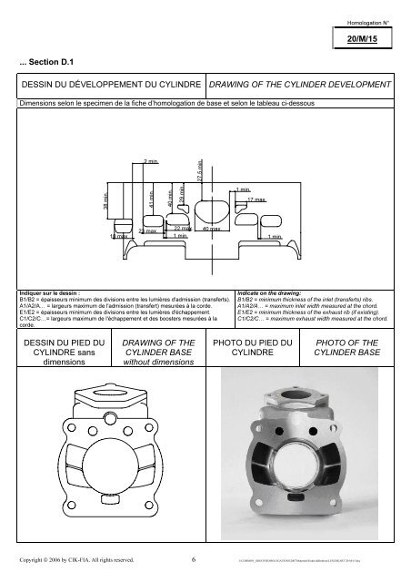
Homologation N°20/M/15... Section D.1DESSIN DU DÉVELOPPEMENT DU CYLINDREDRAWING OF THE CYLINDER DEVELOPMENTDimensions selon le specimen de la fiche d’homologation de base et selon le tableau ci-dessous2 min.27.5 min.38 min.41 min.40 min.29 min.1 min.17 max.22 max.23 max.18 max. 1 min.40 max.1 min.Indiquer sur le dessin :B1/B2 = épaisseurs minimum des divisions entre les lumières d'admission (transferts).A1/A2/A… = largeurs maximum de l'admission (transfert) mesurées à la corde.E1/E2 = épaisseurs minimum des divisions entre les lumières d'échappement.C1/C2/C…= largeurs maximum de l'échappement et des boosters mesurées à lacorde.Indicate on the drawing:B1/B2 = minimum thickness of the inlet (transferts) ribs.A1/A2/A… = maximum inlet width measured at the chord.E1/E2 = minimum thickness of the exhaust rib (if existing).C1/C2/C… = maximum exhaust width measured at the chord.DESSIN DU PIED DUCYLINDRE sansdimensionsDRAWING OF THECYLINDER BASEwithout dimensionsPHOTO DU PIED DUCYLINDREPHOTO OF THECYLINDER BASECopyright © 2006 by CIK-FIA. All rights reserved. 6 J:\COMMON_GROUP\HOMOLOGATIONS\2007\Matériels\Fiches définitives\LENZOKART 20-M-15.doc