SMSB-M21T-AB - Elbro AG
SMSB-M21T-AB - Elbro AG
SMSB-M21T-AB - Elbro AG

Create successful ePaper yourself
Turn your PDF publications into a flip-book with our unique Google optimized e-Paper software.
<strong>SMSB</strong>-<strong>M21T</strong>-<strong>AB</strong> Bedienungsanleitung Manuel de l'utilisateur User Manual Istruzioni per l’usoRELEASE v1.00 27/09/2011
<strong>SMSB</strong>-<strong>M21T</strong>-<strong>AB</strong>Deutsch 3English 10Français 17Italiano 242
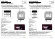
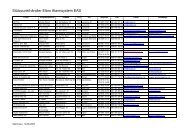
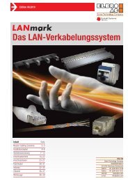
186,0 mm77,5 mm106,1 mm5,0 mm5,0 mm96,0 mm116,1 mm<strong>SMSB</strong>-<strong>M21T</strong>-<strong>AB</strong>Massbilder / Dimensions /Dimensioni8,0 mm13,3 mmØ4,0 mm31,0 mmØ4,0 mm13,3 mm2,0 mm56,8 mm3
<strong>SMSB</strong>-<strong>M21T</strong>-<strong>AB</strong>Sicherheitshinweise Den <strong>SMSB</strong>-<strong>M21T</strong>-<strong>AB</strong> nicht in der Nähe von Herzschrittmachern, Hörgeräten oder medizinischen Apparaten imAllgemeinen installieren. Der <strong>SMSB</strong>-<strong>M21T</strong>-<strong>AB</strong> kann den einwandfreien Betrieb dieser Geräte beeinträchtigen. Der <strong>SMSB</strong>-<strong>M21T</strong>-<strong>AB</strong> arbeitet unter Verwendung eines Funksignals. Kein Mobiltelefonbetreiber kann die Verbindungjederzeit gewährleisten. Aus diesen Gründen kann der <strong>SMSB</strong>-<strong>M21T</strong>-<strong>AB</strong> nicht mit Hausnotrufsystemeneingesetzt werden.Anmerkungen Alle in diesem Handbuch enthaltenen Informationen können ohne Vorankündigung geändert werden. Die Vervielfältigung dieses Handbuchs ist, unabhängig von der jeweiligen Technik und dem dafür eingesetztenMittel sowohl elektronisch als auch materiell einschliesslich Fotokopien oder Speicherung nur dem Benutzerzu persönlichen Zwecken gestattet und ohne besondere schriftliche Genehmigung in allen anderen Fällen verboten. Verwendung, Kopie, Änderung, Auseinanderlegen oder Übertragung der Software sind nur zu den ausdrücklichmit dieser Lizenz genehmigten Zwecken gestattet und ansonsten verboten. Alle anderen genannten Marken oder Produkte beziehen sich auf den jeweiligen Eigentümer.InstallationAus Sicherheitsgründen für den Benutzer und um den einwandfreien Betrieb des <strong>SMSB</strong>-<strong>M21T</strong>-<strong>AB</strong> zu gewährleisten,darf das Gerät ausschliesslich von Fachpersonal installiert werden. Einzuhalten sind ausserdem die nachfolgendaufgeführten Vorschriften:Umgebungsbedingungen Der <strong>SMSB</strong>-<strong>M21T</strong>-<strong>AB</strong> (das Gerät und alle daran angeschlossenen Kabel) ist an Orten zu installieren, die folgendeBedingungen erfüllen: Kein Staub, keine Feuchtigkeit, keine hohen Temperaturen Keine direkte Sonnenbestrahlung Keine Geräte, die Wärme abgeben Keine Gegenstände, die ein starkes elektromagnetisches Feld erzeugen Keine korrosiven Flüssigkeiten oder chemische SubstanzenSchutzartBei der Installation des <strong>SMSB</strong>-<strong>M21T</strong>-<strong>AB</strong> muss folgender IP-Schutzgrad gewährleistet werden: IP54: Nur beim Einsatz für Anwendung im Freien zu gewährleistende SchutzartVersorgung Folgende Vorschriften sind einzuhalten: Keine Kabel mit einer Länge über 2m verwenden Das externe Netzteil (zum Beispiel Steckernetzteil) muss der Europäischen Norm EN 60950 (elektrische Sicherheit)entsprechen. Die Versorgungsspannung darf die maximale Leistung von 24VA nicht überschreiten.Signaleingänge Bei der Installation des <strong>SMSB</strong>-<strong>M21T</strong>-<strong>AB</strong> sind die im Handbuch enthaltenen Hinweise genauestens zu beachten. Die Polarität und die im Handbuch aufgeführten Kenndaten beachten.RelaisausgängeBitte folgende Normen einhalten: Vor dem Anschliessen bitte die technische Daten überprüfen (siehe Kapitel "Technische Daten"); Es dürfen nur doppelisolierte Kabeln mit einem Durchmesser von 6mm verwendet werden; Sicher stellen, dass die Hochspannungsleiter dem markiertem Weg entsprechend verlegt werden, innerhalbder A.T.Fläche; Es dürfen keine Kabel eingeführt werden, die länger als 2m sind, vor allem ausserhalb der markierten Zone; Es wird empfohlen, Niederspannungskabeln von den Hochspannungskabeln zu trennen.4
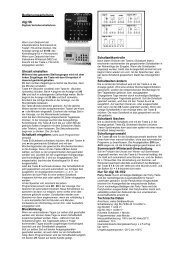
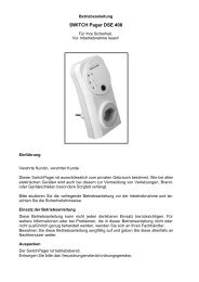
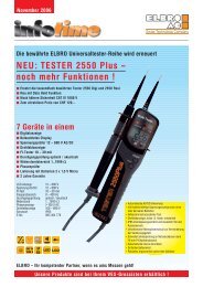
<strong>SMSB</strong>-<strong>M21T</strong>-<strong>AB</strong>Einbauplan5
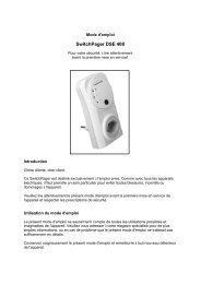
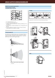
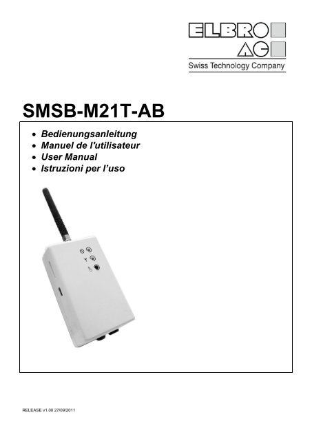
<strong>SMSB</strong>-<strong>M21T</strong>-<strong>AB</strong>Einsetzen der SIM-KartePUSH-PUSHSIM CARD HOLDERPUSHUSB programming portVor dem Einsetzen der SIM-Karte bitte folgendes beachten: PIN-CODE muss mittels handelsüblichem Handy DEAKTIVIERT werden; Combox muss deaktiviert werden;SIM-Karte in den vorgesehenen Schlitz einführen, mit den vergoldeten Kontakten frontseitig gerichtet;Die SIM-Karte darf nur im SPANNUNGSLOSEM ZUSTAND ein- bzw. ausgeschoben werden.Das Gerät funktioniert mit SIM-Karten vom Typ Prepaid und Abo. Auch Daten-SIM-Karten dürfen eingesetzt werden.Letztere sind nur für den Versand und den Empfang von SMS geeignet. Dabei ist die "Anruf-Funktion" nichtmöglich.Anschluss des digitalen AlarmeingangsDas Gerät verfügt über einen Alarm-Eingang, das sowohl beim Schliessen wie auch beim Öffnen des Kontakts einenSMS-Alarm auslöst, an bis zu 6 Usern.Der digitale Eingang ist (gem. Installationsschema) an potentialfreien Kontakten von Maschinen u./o. Schaltern zuverdrahten, in spannungslosem Zustand. Dabei sind die örtlichen Vorschriften einzuhalten.Anschluss der GSM-AntenneDie GSM-Antenne an den SMA-Stecker schrauben (siehe Darstellung im Installationsdiagramm).Anschluss des RelaisausgangsDas Gerät ist mit einem Relaisausgang ausgestattet, der Belastungen bis maximal 0,5A 250VAC (Ohmsche Last)schalten kann. Die Installationsvorschriften unter Berücksichtigung der Nenndaten (siehe entsprechendes Kapitel)sind strikt zu beachten.Die Last kann per SMS und/oder Telefonanruf aktiviert oder deaktiviert werden. Ist das Gerät an ein Heizungs- o-der Klimatisierungssystem angeschlossen, besteht die Möglichkeit, das Ein- und Ausschalten des Geräts je nachRaumtemperatur (Thermostat) zu steuern.ProgrammierungInstallation der ProgrammiersoftwareSchritte zur Installation der Software:Die Mini-CD in das CD-ROM-Laufwerk des PCs einlegen;den automatischen Start der CD-ROM abwarten. Ist die automatische Startfunktion deaktiviert, das Symbol derCD-ROM unter Arbeitsplatz mit einem Doppelklick der rechten Maustaste auswählen und Autoplay anklicken;das Setup-Symbol „Installieren“ anklicken.Achtung: Während der Softwareinstallation muss ggf. Microsoft.NET Framework 4 installiert werden. Eventuell isteine Internetverbindung erforderlich.Programmierung über USB-KabelZur Programmierung muss das Gerät selbst nicht an die Stromversorgung angeschlossen sein, da diese direktüber den USB-Anschluss erfolgt. Das Gerät kann daher vor dem Einbau im Schaltkasten programmiert werden.HINWEIS: Das Relais kann seinen Status nur ändern, wenn es an die Hauptstromversorgung angeschlossen ist.6
<strong>SMSB</strong>-<strong>M21T</strong>-<strong>AB</strong>Die Programmiersoftware starten.Das Gerät per USB-Kabel mit dem PC verbinden.Das Gerät benötigt keinen Installationstreiber, da es von Windows automatisch erkannt wird: Dies vereinfacht eineeventuelle zukünftige Neuprogrammierung des Geräts.Wird das Gerät nicht erkannt und blinkt die Netz-LED weiter rot, im Kapitel über Fehlerbehebung weiterlesen.Die Programmiersoftware <strong>SMSB</strong>-<strong>M21T</strong>-<strong>AB</strong> ist einfach, leicht verständlich und intuitiv. In den nächsten Kapitelnwird jede Funktion bezüglich der Anzeige des betreffenden Programms detailliert erläutert.FunktionenSystempasswortUm die Systemsicherheit zu garantieren, muss ein vierstelliges Passwort (Ziffern und/oder Buchstaben, nur im PC-Modus) eingegeben werden. Dies ist für das Senden der SMS-Befehle unbedingt erforderlich. Die Werks-Einstellung ist viermal null (0000). Für das Senden der SMS-Befehle im entsprechenden Kapitel weiterlesen.Liste der Administrator-BenutzerDiese Liste entspricht dem Verzeichnis der Telefonnummern der Benutzer, die zum Empfangen von SMS-Alarmenund/oder -Benachrichtigungen sowie zur Bedienung des Geräts mithilfe der Schnellbefehle (siehe entsprechendesKapitel) berechtigt sind.Temperaturfühler"Das Gerät verfügt über einen internen Temperatursensor, das die Raumtemperatur ermittelt. Dieser ist ab Werkseinstellungendeaktiviert. Für die Aktivierung kann zwischen folgenden Modi gewählt werden (TMODE):"deaktiviertnur interner FühlerKalibrierenDie Temperatursonde darf kalibriert werden (siehe SMS-Befehl).Achtung: Es wird empfohlen, die Kalibrierung des Sensors nach ca. 30 Minuten Betrieb vorzunehmen, damit derButler die Betriebstemperatur erreicht hat.RaumthermostatfunktionDiese erlaubt die automatische Zuschaltung des Ausgangskontakts des Geräts in Funktion mit der Raumtemperatur.Bei einem entsprechenden Anschluss an ein Heizungs- oder Klimagerät ermöglicht dieses Gerät die Kontrolle derRaumtemperatur, indem sowohl die eventuelle Komforttemperatur Th (heat temperature), AUTOMATIK-Funktion,als auch die eventuelle Erhaltungstemperatur Tf (frost temperature), FROSTSCHUTZ-Funktion, überwacht werden.Die Temperaturgrenzwerte können unproblematisch sowohl über die Software als auch per SMS-Befehle (sieheKapitel über die Befehle) festgelegt werden.Das Gerät besitzt ebenfalls eine Benachrichtigungsfunktion (Notify SMS). Wenn diese aktiviert ist, warnt das Gerätdie Administrator-Benutzer mit einer SMS, wenn die Raumtemperatur 1 °C unter die Frostschutztemperatur Tf(frost temperature) fällt, und sendet diese Nachricht alle 15 Minuten, bis sie vom Benutzer deaktiviert wird.AlarmeingangDas Gerät verfügt über einen Alarm-Eingang, das sowohl beim Schliessen wie auch beim Öffnen des Kontakts einenSMS-Alarm auslöst, an bis zu 6 Usern. Der Text jedes Ereignisses kann sowohl mittels Software als auch perSMS-Befehl benutzerdefiniert werden.Dank dieser Funktion wird der Benutzer über bestimmte Ereignisse der Systeme oder Anlagen, an die das Gerätangeschlossen ist, informiert. Dabei kann es sich beispielsweise um eine eventuelle Störung des Heizkessels, einenSpannungsabfall oder das Öffnen eines Ventils usw. handeln.TelefonanruffunktionDas Gerät kann eine Liste von Telefonnummern mit den entsprechenden Namen (maximal 300) speichern, die berechtigtsind, den Relaisausgang durch einen einfachen kostenlosen Telefonanruf zu aktivieren/deaktivieren. DasGerät erkennt den eingehenden Anruf, quittiert ihn unverzüglich und aktiviert gleichzeitig die angeschlossene Anlage.7
<strong>SMSB</strong>-<strong>M21T</strong>-<strong>AB</strong>Diese Funktion (RMODE) kann wie folgt eingerichtet werden:Funktion deaktiviertSWITCH-Modus (Umschalten): das Relais wird umgeschaltet (EIN/AUS); in diesem Modus wird die Thermostatfunktiondauerhaft deaktiviert;PULSE-Modus (Impuls): ausgeführt wird ein Impuls (programmierbar von 1 bis 20 Sekunden); in diesem Moduswird die Thermostatfunktion dauerhaft deaktiviert;AUTOMATIC-Modus (automatisch): ermöglicht die Aktivierung des automatischen Betriebs des Raumthermostats(natürlich nur, wenn der Temperaturfühler zuvor aktiviert wurde).Der Benutzer kann zudem die Option sms feedback (SMS-Rückmeldung) aktivieren: An das Mobiltelefon, vondem der Anruf einging, wird eine SMS zur Bestätigung des Anlagenzustands gesendet.Im PULSE-Modus kann der Text der SMS-Bestätigung des gesendeten Befehls zudem benutzerdefiniert werden.GuthabenfunktionMit dieser innovativen Funktion für aufladbare SIM-Karten kann der Benutzer über das Restguthaben auf der SIM-Karte, an die das Gerät angeschlossen ist, informiert werden.Da jeder Telefonanbieter unterschiedliche Methoden zum Abfragen des Guthabens hat, kann diese Funktion aufdrei verschiedene Arten eingerichtet werden, die den normalerweise bei Telefonanbietern gängigen Verfahren entsprechen: über Schnellbefehl; über das Anrufen einer Nummer, um eine SMS-Nachricht mit Angabe des Guthabens zu empfangen; über eine kostenlose SMS mit einem Befehl zum Empfangen des Guthabens.Setzen Sie sich mit Ihrem Telefonanbieter in Verbindung, um zu erfahren, welche Parameter Sie eingeben müssen.Diese Funktion wird nicht zu 100 % garantiert, denn jeder Telefonanbieter benutzt ein anderes Verfahren, um Informationenüber das Restguthaben abfragen zu lassen. Diese werden außerdem ständig weiterentwickelt.SchnittstellenGSM LED: GSM-SignalstärkeDiese LED zeigt die GSM-Signalstärke an. In der nachfolgenden Tabelle wird die Funktionsweise beschrieben:Farbe der LEDDAUERLICHT ROTBLINKLICHT ROTBeschreibungDas Gerät empfängt kein Signal und/oder ist nicht im Netzwerk registriertFehler: Verwiesen wird auf das Kapitel Fehlerbehebung.BLINKLICHT GRÜN Die Zahl der Blinksignale entspricht der GSM-Signalstärke: 1 bis 5.DAUERLICHT GRÜNDas Gerät sendet oder empfängt SMS.STATUS LED: Status des RelaisausgangsSiehe nächstes KapitelTaste zum manuellen UmschaltenDas Betätigen dieser Taste hat je nach aktivierten Funktionen verschiedene Auswirkungen.Funktion Wirkung LED RelaisstatuskeineDas Relais wechselt seinen Zustand von AUS zu EINund umgekehrtROT: AUSGRÜN: EINAUTO: EIN Das Gerät deaktiviert die Automatik-Funktion und den ROT: AUSRelaisausgangFROST: EIN Das Gerät schaltet vom Frostschutzmodus in den Automatik-Modusum und umgekehrtRote Blinksignale: FROSTSCHUTZ-ModusGrüne Blinksignale: AUTOMATIK-ModusRMODE:PULSEDas Gerät führt den Impuls ausROT: AUSGRÜN: EINSMS-BefehleDas Gerät verfügt über eine Reihe von Konfigurations- und Steuerungs-/Schaltbefehlen, die über SMS gesendetwerden können. Der SMS-Befehl ist passwortgeschützt (siehe Kapitel Systempasswort).Der SMS-Befehl hat folgendes Format:[PASSWORD]#[BEFEHL] Beispiel: 0000#1 (Relais ein)Wobei Folgendes gilt: das Passwort ist stets vierstellig;8
<strong>SMSB</strong>-<strong>M21T</strong>-<strong>AB</strong>#: das Rautenzeichen ist ein obligatorisches Trennzeichen (alternativ kann auch nur das Punktzeichen verwendetwerden).Nachfolgend ist eine Liste der verfügbaren Standardbefehle mit entsprechender Beschreibung und einem Beispielaufgeführt:Befehl Beschreibung Beispiel Feedback0 Relaisausgang deaktivieren (AUTO-Funktion wird deaktiviert) 0000#0 OFF1 Relaisausgang aktivieren (AUTO-Funktion wird deaktiviert) 0000#1 ON? Abfrage des aktuellen Zustands 0000#? Aktueller ZustandAAUTO-Funktion aktivieren.0000#A Th: 20CHingewiesen wird auf den vorhergehenden Schwellenwert, vorgegebenerWert 20 °C.A[1-50] AUTO-Funktion aktivieren und Schwellenwert festlegen. 0000#A25 Th: 25CFFROSTSCHUTZ-Funktion aktivieren.Hingewiesen wird auf den vorhergehenden Schwellenwert, vorgegebenerWert 8°C*.0000#F Tf: 8CNachfolgend ist eine Liste der verfügbaren erweiterten Befehle (die die Software-Benutzung vermeiden) mit entsprechenderBeschreibung und Beispiel aufgeführt:Befehl Beschreibung Beispiel FeedbackF0 Deaktivieren FROSTSCHUTZ-Funktion 0000#FF[1-49] FROSTSCHUTZ-Funktion aktivieren und Schwellenwert festlegen. 0000#F6 Tf: 6CI Zustand des Eingangskontakts anzeigen. 0000#IN[0-1] 0: Frostschutzbenachrichtigung deaktivieren0000#N0 NOTIFY: OFF1: Frostschutzbenachrichtigung aktivieren0000#N1 NOTIFY: ONP Systempasswort ändern 0000#P1234 new Password 1234S[1-2]? Text der aktuellen Meldung anzeigen 0000#S1?S1: Text des Eingangs Nr. 1 Ereignis Kontakt unterbrochen ändern 0000#S1:input 1 openedS2: Text des Eingangs Nr. 1 Ereignis Kontakt geschlossen ändern 0000#S2:input 1 closedT[0-1] 0: Temperatur deaktivieren1: nur internen Fühler aktivieren0000#T00000#T1T+Fühler kalibrieren: nur bei TMODE = 1 oder 20000#T+1T-0000#T-3U? Liste der vorherigen Benutzer anzeigen 0000#U?U[1-6]- Einen Benutzer aus der Liste löschen 0000#U2-U[1-6]:[num] Bestimmten Benutzer hinzufügen oder ändern 0000#U1:+4112345678Achtung: Das Gerät darf nicht zu Frostschutz-Sicherheitszwecken eingesetzt werdenTMODE: OFFTMODE: INTAktualisierter Zustand9
<strong>SMSB</strong>-<strong>M21T</strong>-<strong>AB</strong>SchnellbefehleDas Gerät verfügt über eine Reihe von Schnellbefehlen, für die kein Passwort erforderlich ist und die ausschließlichvon den Administrator-Benutzern gesendet werden können. Nachfolgend ist eine Liste aufgeführt:Befehl Beschreibung Beispiel FeedbackOFF Relaisausgang deaktivieren (AUTO-Funktion wird deaktiviert) OFF OFFON Relaisausgang aktivieren (AUTO-Funktion wird deaktiviert) ON ONSTATUS Abfrage des aktuellen Zustands STATUS Aktueller ZustandAUTO AUTO-Funktion am zuvor einprogrammierten Schwellenwert aktivieren AUTO Th: 20CHinweis: Die gesendeten Befehle müssen in Großbuchstaben geschrieben sein und dürfen keine Leerschritte aufweisen.FehlerbehebungBei Störungen sendet die LED zur Fehleranzeige rote Blinksignale.Zum Identifizieren des unten aufgeführten Fehlercodes die Blinksignale zählen:BlinksignaleBeschreibung5 Systemfehler: Das Gerät neu starten.1 Die SIM-Karte ist durch einen PIN-Code geschützt.3 Keine SIM-Karte.LED AUSSystemfehler: Das Gerät neu starten. Liegt das Problem weiterhin vor, den Kundendienst benachrichtigen.KenndatenGSM Dual-band mode 900Mhz ,1800MHzVersorgung Anschlussspannung: 12V DC (9-24VDC) Stromstärke: Imax = 1000mA Die Versorgungsspannung darf die maximale Leistung von 24VA nicht überschreiten. Versorgung gegen Polaritätsumkehrung abgesichertRelaisausgang 1 Relay SPDTo 0,5A, 250V AC (Ohmsche Last);o 1A, 30V DC.Eingänge 1 digital-Eingang (VCC)Haupteigenschaften Gehäuse für Schiene EN-50022: UL94V-0; Schutzart: IP20. Standardbetriebstemperatur: von -5°C bis +45°C; maximaler Querschnitt der Leiter, die in die Klemmen eingesetzt werden können: 2,5mm 2 ; USB-ProgrammierportGeprüft nachHealth and Safety: EN 62311 (2008) EN 60950-1 (2006) + A11 (2009)Electromagnetic Compatibility: EN 301489-1 V1.8.1 (2008) EN 301489-7 V1.3.1 (2005)Effective use of radio spectrum: EN 301511 V9.02 (2003)Verbrauch(Standardwerte)Standby 40mASenden/Empfangen SMS 200mASoftwareanforderungenIn der nachfolgenden Tabelle sind die von der Software <strong>SMSB</strong>-<strong>M21T</strong>-<strong>AB</strong> unterstützten Betriebssysteme aufgeführt.BetriebssystemNotesWindows XP SP3 dieser software wird auf IA-64-basierten Systemen (Itanium) nicht unterstützt.Um die bestmögliche Kompatibilität und höchste Sicherheit zu gewährleisten, wird für alle PlattformenWindows Vista SP2empfohlen, ein Upgrade auf das neueste Windows Service Pack durchzuführen und wichtige UpdatesWindows 7 zu installieren, die auf der Windows Update-Website verfügbar sind.10
<strong>SMSB</strong>-<strong>M21T</strong>-<strong>AB</strong>Safety Information Do not install the <strong>SMSB</strong>-<strong>M21T</strong>-<strong>AB</strong> device close to pacemakers, auditory prostheses or medical devices in generalas the <strong>SMSB</strong>-<strong>M21T</strong>-<strong>AB</strong> device may interfere with the operation of these devices. The <strong>SMSB</strong>-<strong>M21T</strong>-<strong>AB</strong> device operates by means of a radio signal, no mobile telephone operator is capable ofensuring a connection at all times. For this reason, the <strong>SMSB</strong>-<strong>M21T</strong>-<strong>AB</strong> device cannot be used in life supportsystems.Notes All information contained in this manual is subject to change without prior notice. No part of this manual may be reproduced, in any form or by any means, electronic or physical, or otherwise,including photocopying or storage, for needs other than the personal use of the user, without the prior writtenpermission by ELBRO <strong>AG</strong>. The use, copying, modification, disassembly or transmission of the software is forbidden. For any other trademark or product cited reference is made to relative owner.InstallationIn order to ensure the operator's safety and the correct operation of the <strong>SMSB</strong>-<strong>M21T</strong>-<strong>AB</strong> device, the device shouldbe installed exclusively by qualified staff. The rules listed below should also be strictly ob-served.Environmental conditionsThe <strong>SMSB</strong>-<strong>M21T</strong>-<strong>AB</strong> device (the instrument and all cables connected to it) should be installed in places either freeor far from: Dust, humidity, great heat; Direct exposure to sunlight; Objects radiating heat; Objects generating a strong electromagnetic field; Liquids or corrosive chemical substances.Degree of ProtectionDuring the installation of the <strong>SMSB</strong>-<strong>M21T</strong>-<strong>AB</strong> device, the following degree of protection is to be ensured: IP54: protection to be guaranteed when using the device outdoors.Power supplyObserve the following rules: Do not use cables longer than 2m; The external power supply unit (e.g. mains charger), must comply with the EN 60950 Directive (electrical safety); The device must be powered by a power source limited to 24VA.Signalling InputsObserve the following rules: do not use cables longer than 2m; do not install the cables in proximity of possible electromagnetic fields, in which case, use shielded cables.Relay OutputObserve the following rules: before connecting the load, check the data rating.(see "rating"); use insulated cables suitable for the load with double sheath (double insulation), with 6 mm outer sheath diameter; ensure that dangerous voltage cables go along the path indicated only remaining within the A.T. area; do not put a cable longer than expected (2m), and especially outside the indicated areas; you should never bring dangerous voltage cables close the low voltage.11
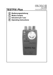
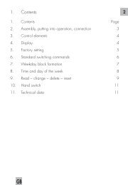
<strong>SMSB</strong>-<strong>M21T</strong>-<strong>AB</strong>Installation diagram12
<strong>SMSB</strong>-<strong>M21T</strong>-<strong>AB</strong>Inserting the SIM cardBefore inserting the SIM card, proceed as follows: DIS<strong>AB</strong>LE THE PIN CODE using a mobile phone; Disable the answering machine.Insert the SIM card with its gold contacts facing toward the front, into the slot.The SIM card is always to be inserted and/or removed with the device TURNED OFF.The device works with either prepaid or subscription SIM cards as well as data SIM cards. The latter, however, areonly enabled for sending and receiving SMS messages, so the “phone ring” function cannot be used.Connecting the Digital Alarm InputThe device has an alarm input, which allows you to send a text message to, both opening and closing of each contact,administrative users.Connect the contacts of the input (as illustrated in the installation diagram) to the contactors, remote switchesand/or electromechanical switches, when there is no electrical potential (voltage free contact) and in strict conformancewith the regulations in force.Connecting the GSM AntennaScrew the GSM antenna into the SMA connector.Connecting the Relay OutputThe device has a relay output that handles power loads of up to 0,5A 250VAC (resistive). Follow the installation instructionscarefully according to the data plate indications (see corresponding section).The device may be activated or deactivated by an SMS and/or telephone ring. If the device is connected to a heatingor air-conditioning system, it may be turned on and off according to the room temperature (thermostat).ProgrammingInstalling the Programming SoftwareTo install the software, proceed as follows:Insert the mini-CD in the CD-ROM drive of the PC;Wait for the CD-ROM to run automatically. If this feature is disabled, open Explorer, right click on the CD-ROMicon and then click on Autoplay.Click on the “Install” setup iconWarning: during the software installation procedure it may be necessary to install Microsoft .NET Framework 4. Aninternet connection may also be necessary.13
<strong>SMSB</strong>-<strong>M21T</strong>-<strong>AB</strong>Programming the Device Using a USB CableThe device needs no power supply connection during the programming procedure as the power is supplied directlyby the USB connection. The device may therefore be programmed before installing it in the control panel.NOTE: the relay cannot change status if the main power supply is not present. Start the programming software. Connect the USB cable to the PC and the device.The device needs no installation driver as it is recognized automatically by Windows: this feature makes it easier toreprogram the device, where necessary, in the future.If the device is not recognized and the network LED continues to blink red, see the troubleshooting section.The programming software of <strong>SMSB</strong>-<strong>M21T</strong>-<strong>AB</strong> is clear, simple and self-explanatory. The sections that follow providea detailed description of each of the functions in the order in which they are displayed by the program.FunctionsSystem PasswordIn order to ensure the security of the system, the device prompts the operator to enter a password of four digits(and/or characters, in PC mode only) indispensable to be able to send command SMS messages. The defaultpassword is four zeros (0000). For instructions on how to send command SMS messages, see the correspondingsection.List of Administrator UsersThis list is made up of the telephone numbers of the users authorized to receive the alarm and/or notification SMSmessages and to control the device using quick commands (see corresponding section).Temperature SensorThe device has an internal sensor that can detect the ambient temperature. For default settings, the sensor is disabled.The user may choose between the following operating modes (TMODE): sensor disabled sensor enabledCalibrationIt is possible to calibrate the temperature meadured by probe (see:commands sms).Note: It is reccomended to calibrate the sensor after about 30 minutes of running, so the device has reached operatingtemperatureRoom Thermostat FunctionIt allows you to control the relay output according to the ambient temperature measured by the temperature probe.When connected to a heating or air-conditioning system, this device enables the temperature of a room to be controlledby monitoring both the comfort temperature Th (heat temperature), the AUTOMATIC function, where present,and the maintenance temperature Tf (frost temperature), the ANTIFREEZE function.The temperature thresholds may be set either using the software or from a remote location by means of commandsms (see the Commands section).The device also has a notification function (Notify SMS), which, when activated, enables the device to inform itsadministrator users through an SMS if the room temperature drops 1°C below the frost temperature (Tf), sent repeatedlyevery 15 minutes until it is disabled by the user.14
<strong>SMSB</strong>-<strong>M21T</strong>-<strong>AB</strong>Alarm InputThe device has an alarm input, which allows you to send a text message to, both opening and closing of each contact,administrative usersThe text associated with each event may be customized from the software or through a command SMS.This function informs the user of specific events that take place on the system or plant to which the device is connectedsuch as a boiler breakdown or voltage drop, the opening of a valve, etc..Phone Ring FunctionThe device can store a list of telephone numbers and names (up to three hundred) authorized to activate and/ordeactivate the relay output simply by a telephone ring and thus with no cost whatsoever. The device recognizes theincoming call, cuts if off immediately and activates the plant to which it is connected.This function (RMODE) may be set in the following modes:function disabled;SWITCH mode: the relay is simply toggled ON and OFF; (this mode permanently disables the thermostat function);PULSE mode: a programmable pulse of one to twenty seconds is emitted (this mode permanently disables thethermostat function);AUTOMATIC mode: used to activate the automatic room thermostat function (providing the temperature sensorhas been activated).The user may also choose to activate the sms feedback option, which sends an SMS confirming the status of theplant back to the mobile phone from which the telephone ring was received.PULSE mode also enables the text of the SMS confirming the command executed to be customized.Credit FunctionThis is an innovative function for rechargeable SIM cards that informs the user at a remote location of the residualcredit on the SIM card to which the device is connected.As each telephone company adopts a different method of indicating the residual credit to users, this function maybe set in one of the following three modes most commonly used by telephone operators: Using a quick command; By calling a number to receive an SMS indicating the credit; By means of a free SMS with a command for receiving the credit indication.To find out the specific parameters to be entered, we recommend you consult your telephone company.This function is not fully guaranteed as the telephone companies not only adopt different methods to indicate theresidual credit to users but they also change these methods continually.InterfacesGSM LED: GSM Signal LevelThis LED identifies the level of the GSM signal. Its operation is described in the table below:REDFLASHING REDLED colourDescriptionThe device is receiving no signal and/or is not registered on the networkError situation: see the troubleshooting sectionFLASHING GREEN The number of flashes identifies the level of GSM field: it may range from 1 to 5.GREENSTATUS LED: Status of the Relay OutputSee the section below.The device is receiving or sending an SMS15
<strong>SMSB</strong>-<strong>M21T</strong>-<strong>AB</strong>Manual Switch ButtonThe operation of this button depends on the functions activated.Function Operation Relay status LEDNoneThe relay changes status from OFF to ON and vice versaRED: OFFGREEN: ONAUTO: ONThe device deactivates the automatic function and the RED: OFFrelay outputFROST: ONThe device switches from antifreeze to automatic andvice versaFlashing red light: ANTIFREEZEFlashing green light: AUTOMATICRMODE: PULSE The device emits the pulse RED: OFFGREEN: ONCommand SMSThe device has a series of setup and control commands that may be sent by SMS. The command message is protectedby a password (see the system password section).The command message has the following format:[PASSWORD]#[COMMAND] for example: 0000#1 (turn relay on)Where:the password always has 4 characters; #: hash is an obligatory separator (only the dot character may be used as an alternative).The table below contains a list of the standard commands available together with their description, for example:Command Description Example Response0 Turns off the relay output (disables AUTO) 0000#0 OFF1 Turn on the relay output (disables AUTO) 0000#1 ON? Finds out the current status 0000#? Current statusATurns on the AUTO function.0000#A Th: 20CAdopts the previous threshold value; 20°C by defaultA[1-50] Enables the AUTO function and sets the threshold. 0000#A25 Th: 25CFEnables the FROST function.0000#F Tf: 8CAdopts the previous threshold value; 8°C* by defaultThe table below lists the advanced commands available (without having to use the software) together with their description,for example:Command Description Example ResponseF0 Disables FROST function 0000#F0F[1-49] Enables the FROST function and sets the threshold. 0000#F6 Tf: 6CI Shows the status of the contact of the input 0000#IN[0-1] 0: disables antifreeze notification0000#N0NOTIFY: OFF1: enables antifreeze notification0000#N1NOTIFY: ONP Changes the system password 0000#P1234 new password 1234S[1-2]? Shows the text of the current message 0000#S1?S1: Modifies the text of input no.1 contact opening 0000#S1:input 1 openedS2: Modifies the text of input no. 1 contact closure 0000#S2:input 1 closedT[0-1] 0: disables the temperature1: enables internal sensor only0000#T00000#T1T+Calibrates the sensor: only with TMODE=10000#T+1T-0000#T-3U? Shows the list of previous administrator users 0000#U?U[1-6]- Removes a user from the list 0000#U2-U[1-6]:[num] Adds or modifies the specified user 0000#U1:+3912345678* Warning: Do not use this device as a safety device frostTMODE: OFFTMODE: INTUpdated status16
<strong>SMSB</strong>-<strong>M21T</strong>-<strong>AB</strong>Quick CommandsThe device has a series of quick commands without any need for a password, which may be sent exclusively byadministrator users. These commands are listed in the table below:Command Description Example ResponseOFF Turns the relay output off (disables AUTO) OFF OFFON Turns the relay output on (disables AUTO) ON ONSTATUS Finds out the current status STATUS Current statusAUTO Activates the AUTO function at the threshold programmed previouslyAUTO Th: 20CNote: the commands sent must consist exclusively of capital letters and with no spaces.TroubleshootingIf a fault arises, the error signalling LED will flash red. Count the number of flashes to identify the error code as indicatedin the table below:Flashing codeDescription1 System error: try restarting the device2 The SIM card is protected by a PIN code3 The SIM card is not presentLED OFFSystem error: try restarting the device. If the problem persists, call the technical serviceNameplate DataGSM Section Dual-band mode 900Mhz ,1800MHzPower suppy Supply voltage: 12V DC (9-24V) Current: Imax = 1000mA The device must be powered by a power source limited to 24VA. Power supply protected against reversed polarityOutput 1 Relay SPDTo 0,5A, 250V AC (Resistive);o 1A, 30V DC.Input 1 digital input (VCC)Main characteristics Degree of infiammability: UL94V-0 Protection degree: IP20 Standard operating temperature: -5°C to +45°C Max conductor size: 2,5mm 2 USB programming portCertificationsCurrent drawn(typical values)Health and Safety: EN 62311 (2008)Electromagnetic Compatibility: EN 301489-1 V1.8.1 (2008)Effective use of radio spectrum: EN 301511 V9.02 (2003)Standby 40mASending\Receiving SMS 200mA EN 60950-1 (2006) + A11 (2009) EN 301489-7 V1.3.1 (2005)Software RequirementsThe following table lists the operating systems supported by the software <strong>SMSB</strong>-<strong>M21T</strong>-<strong>AB</strong>.Operating systemNOTEWindows XP SP3Windows Vista SP2Windows 7The .NET Framework Client Profile is not supported on IA-64-based (Itanium) systems.For all platforms, we recommend that you upgrade to the latest Windows Service Pack and critical updates availablefrom the Windows Update Web site to ensure the best compatibility and security.17
<strong>SMSB</strong>-<strong>M21T</strong>-<strong>AB</strong>Consignes de sécuritéNe pas installer le <strong>SMSB</strong>-<strong>M21T</strong>-<strong>AB</strong> à proximité de pacemakers, prothèses auditives ou dispositifs médicaux en général. Le <strong>SMSB</strong>-<strong>M21T</strong>-<strong>AB</strong> peut interférer avec le bon fonctionnement de ces appareils.Parce que le <strong>SMSB</strong>-<strong>M21T</strong>-<strong>AB</strong> fonctionne grâce à l’utilisation d’un signal radio, aucun opérateur de téléphonie mobile n’est en mesure degarantir une liaison à tout moment. C’est la raison pour laquelle le <strong>SMSB</strong>-<strong>M21T</strong>-<strong>AB</strong> ne peut pas être utilisé dans des systèmes de maintienartificiel des fonctions vitales.RemarquesToutes les informations contenues dans ce manuel sont sujettes à modification sans préavis.La reproduction de ce manuel, de quelque façon que ce soit et par quelque moyen que ce soit, sur support papier ou électronique, y comprisles photocopies ou la mémorisation à des fins autres que l’utilisation personnelle de l’usager, est interdite, sauf dans les cas expressémentprévus par ELBRO <strong>AG</strong> et faisant l’objet d’une autorisation écrite.L’utilisation, la modification, le démontage ou le transfert du logiciel sont interdits.Toute autre marque ou tout autre produit cité(e) se réfère à son propriétaire respectif.InstallationAfin de préserver la sécurité et l’intégrité physique de l’opérateur, tout comme le bon fonctionnement du système,l’installation du <strong>SMSB</strong>-<strong>M21T</strong>-<strong>AB</strong> doit être uniquement confiée à un personnel qualifié. De même, les règles décritesci-dessous doivent être respectées.Conditions ambiantesLe <strong>SMSB</strong>-<strong>M21T</strong>-<strong>AB</strong> (l’appareil et l’ensemble des câbles reliés à ce dernier) doit être installé dans des locaux dépourvusde, ou éloignés des sources suivantes: Poussière, humidité, température élevée; Exposition directe aux rayons du soleil; Objets qui émettent de la chaleur; Objets qui génèrent un fort champ électromagnétique; Liquides ou substances chimiques corrosives.Degré de protectionDurant l’installation du <strong>SMSB</strong>-<strong>M21T</strong>-<strong>AB</strong>, il est fondamental de maintenir le degré de protection suivant: IP54: degré de protection qui doit être garanti en cas d’utilisation avec des applications extérieuresAlimentationRespecter les règles suivantes: Ne pas utiliser de cordons de plus de 2m de long; Le bloc d’alimentation extérieur (ex: bloc d’alimentation incorporé) doit être conforme à la directive EN 60950(sécurité électrique); La tension d'alimentation ne doit pas dépasser la puissance maximale de 24VA.Entrées de signalisationRespecter les règles suivantes: Ne pas utiliser de cordons de plus de 2m de long; Ne pas installer les câbles proche des champs électromagnétiques, dans ce cas, utiliser des câbles blindés.Sorties relaisRespectez les règles suivantes: Avant de brancher le charge, contrôler les données techniques (voir chapitre «données techniques»); utilisez des câbles appropriés à la charge avec une gaine à double isolation, avec un diamètre de 6 mm de lagaine externe; s'assurer que les câbles de tension dangereuse parcourent l'itinéraire indiqué, en restant dans la zone A.T.; ne pas mettre un câble plus long que prévu (2m), et surtout en dehors des zones indiquées; il est recommandé de séparér les câbles basse tension des câbles de haute tension."18
<strong>SMSB</strong>-<strong>M21T</strong>-<strong>AB</strong>Schéma d'installation19
<strong>SMSB</strong>-<strong>M21T</strong>-<strong>AB</strong>Insertion de la carte SIMAvant d'insérer la carte SIM, vous devez: DESACTIVER LE CODE PIN à l'aide d'un téléphone mobile; Coupez le répondeur.Insérez la carte SIM dans la fente avec ses contacts dorés vers vers l'avantLa carte SIM PEUT être insérée et / ou supprimée uniquement lorsque l'APPAREIL est ÉTEINT.L'appareil fonctionne avec les cartes SIM de type prépayé et abonnement. Aussi les DATA-SIM peuvent être utilisés.Ces derniers ne font que envoier et récevoir des SMS. La fonctionne '"Appel" n'est donc pas possible.Branchement des entrées numériques de signalisation d’alarmeL'appareil dispose d'une entrée d'alarme, ce qui vous permet d'envoyer un message texte à la fois l'ouverture et lafermeture du contact, jusqu'à un maximum de six utilisateurs.Connectez le contact de l'entrée (comme montré dans le schéma d'installation) à les contacteurs, télérupteurs et /ou des commutateurs électromécaniques, en l'absence de potentiel électrique (tension) et en adhérant strictementà la loi.Branchement de l’antenne GSMVisser l’antenne GSM au connecteur SMA en suivant l’illustration du schéma d’installation.Branchement de la sortie relaisL’appareil est équipé d’une sortie relais qui est en mesure de gérer des charges de puissance électrique allantjusqu’à 0,5A 250VAC maximum (résistives). Il convient de respecter scrupuleusement la réglementation en matièred’installation et de se reporter aux informations imprimées sur la plaquette signalétique (voir le chapitre correspondant).Possibilité d’activer ou de désactiver la charge par le biais d’un SMS et/ou d’un appel sans réponse. Si l’appareilest raccordé à un système de chauffage ou à un climatiseur, la mise sous tension et la mise hors tension de cedernier peuvent être commandées en fonction de la température ambiante (thermostat).ProgrammationInstallation du logiciel de programmationLa procédure d’installation du logiciel est la suivante : Insérer le mini-CD dans le lecteur de CD-ROM de l’ordinateur ; Attendre le lancement automatique du CD-ROM. Si le lancement automatique est désactivé , ouvrir Poste detravail et cliquer avec la touche droite de la souris sur l’icône du CM-ROM, puis sur Autoplay (Lecture automatique); Cliquer sur l’icône d’installation « Installa » (Installer).Attention : l’installation du logiciel nécessite parfois l’installation de Microsoft .NET Framework 4. Une connexionInternet peut être demandée.20
<strong>SMSB</strong>-<strong>M21T</strong>-<strong>AB</strong>Programmation par l’intermédiaire d’un câble USBLa programmation de l’appareil peut se faire avec l’alimentation coupée, dans la mesure où celle-ci est directementfournie par la connexion USB. Il est donc possible d’effectuer la programmation de l’appareil avant de l’installerdans l’armoire électrique.REMARQUE : impossible de permuter l’état du relais en l’absence de l’alimentation principale.Lancer le logiciel de programmation.Brancher le câble USB de l’ordinateur à l’appareil.Parce que Windows est en mesure de reconnaitre automatiquement l’appareil, aucun pilote d’installation n’est exigé: un avantage qui simplifie une éventuelle reprogrammation de l’appareil à l’avenir.Si l’appareil n’est pas reconnu et que le témoin réseau continue à clignoter en rouge, consulter le chapitre consacréà la résolution des pannes.Le logiciel de programmation du <strong>SMSB</strong>-<strong>M21T</strong>-<strong>AB</strong> est simple, clair et ne nécessite aucune explication. Les prochainschapitres aborderont en détail chacune des fonctions selon l’ordre dans lequel le programme en questionles affiche.FonctionsMot de passé systèmeDans le but de garantir la sécurité du système, l’appareil demande la saisie d’un mot de passe composés dequatre chiffres (et/ou caractères selon le mode d’exploitation de l’ordinateur) indispensable à l’envoi des SMS decommande. Le mot de passe prédéfini est quatre zéros (0000). Pour l’envoi des SMS de commande, consulter lechapitre correspondant.Listes des utilisateurs et administrateursCette liste correspond à la liste des numéros de téléphone des utilisateurs habilités à recevoir des SMS d’alerteet/ou de notification et à commander l’appareil par le biais de commandes rapides (voir le chapitre correspondant).Capteur de températureL'appareil dispose d'un capteur interne qui permet de détecter la température ambiante. Par défaut, le capteur estdésactivé. Pour l'activer, vous pouvez choisir parmi les modes suivants (TMODE) :désactivéscapteur embarqué uniquementÉtalonnageIl est possible de calibrer la température détectée par la sonde (voir la commande SMS).Attention: Avant d'effectuer l'étalonnage de la température ambiante, attendre au moins 30 minutes del’enclenchement de l'appareil pour rejoindre la température de fonctionnement.Fonction ThermostatIl vous permet de contrôler la sortie du relais en fonction de la température mesurée par la température ambiante.Correctement raccordé à un système de chauffage ou à un climatiseur, ce dispositif permet de contrôler la températured’une pièce en surveillant aussi bien la température de confort éventuelle Th (heat temperature) - fonctionAUTOMATIQUE que l’éventuelle température de maintien Tf (frost temperature) - fonction ANTIGEL.Possibilité de configurer commodément les seuils de température aussi bien à travers le logiciel qu’en mode télécommandépar le biais de SMS de commande (voir le chapitre traitant des commandes).L’appareil dispose également d’une fonction de notification (Notify SMS) ; une fois habilitée, l’appareil avertit lesutilisateurs administrateurs en leur envoyant un SMS dès que la température ambiante baisse d’un degré °C endessousde la température antigel Tf (frost temperature) ; le SMS sera renvoyé toutes les 15 minutes jusqu’à ceque l’utilisateur ait procédé à la désactivation.21
<strong>SMSB</strong>-<strong>M21T</strong>-<strong>AB</strong>Entré de signalisationLe dispositif est muni de une entrés de signalisation, il permet d’envoyer un SMS aux utilisateurs administrateursaussi bien lors de l’ouverture que de la fermeture de chaque contact.Le texte de chaque événement peut être personnalisé soit par logiciel, soit par l’envoi d’un SMS de commande.Cette fonction permet à l’utilisateur d’être informé sur des événements spécifiques liés au système ou àl’installation auxquels l’appareil est relié, comme par exemple, un éventuel dysfonctionnement de la chaudière ouune chute de courant, l’ouverture d’une soupape, etc.Fonction « appel sans réponse »L’appareil est en mesure de mémoriser une liste de numéros de téléphone accompagnés des noms correspondants(jusqu’à trois cent maximum) qui sont habilités à activer et/ou désactiver la sortie relais sur simple appelsans réponse gratuit. Le dispositif reconnait l’appel entrant et le prend immédiatement en charge, tout en activantsimultanément l’installation à laquelle il est relié.Cette fonction (RMODE) peut être configurée selon les modes suivants : fonction désactivée ; mode SWITCH (commutation) : effectué sur simple commutation du relais (ON/OFF) ; (mode qui désactive lafonction thermostat de manière permanente) ; mode PULSE (impulsion) : envoi d’une impulsion programmable entre une et vingt secondes (mode qui désactivela fonction thermostat de manière permanente) ; mode AUTOMATIC (automatique) : permet d’activer la fonction automatique du thermostat ambiant (à conditionque le capteur de température ait été activé auparavant).L’utilisateur peut également décider d’activer la fonction sms feedback (SMS de réponse) qui permet de recevoirun SMS confirmant l’état de l’installation sur le téléphone portable depuis lequel l’appel sans réponse a été effectué.Le mode PULSE permet par ailleurs de personnaliser le texte du SMS confirmant l’exécution de la commande.Fonction Unités de créditIl s’agit d’une fonction toute à fait innovante pour les cartes SIM rechargeables qui permet de communiquer àl’utilisateur à distance les unités de crédit dont il dispose encore sur la carte SIM à laquelle l’appareil est relié.Parce que chaque opérateur de téléphonie mobile a sa propre méthode pour interroger les unités de crédit, il estpossible de configurer cette fonction selon les trois modes standards détenus à ce jour par les opérateur de téléphoniemobile : Commande rapide ; Appel d’un numéro qui permet de recevoir un SMS de crédit ; SMS gratuit avec commande pour recevoir le solde.Pour connaître les paramètres spécifiques à saisir, il est conseillé de consulter son opérateur de téléphonie mobile.Cette fonction n’est cependant pas fiable à 100 %, dans la mesure où chaque opérateur de téléphonie mobile a sapropre méthode de consultation du trafic résiduel et que ce domaine est lui aussi en perpétuelle évolution.InterfacesGSM LED: niveau du signal GSMCe voyant identifie le niveau du signal GSM. Le tableau suivant décrit son fonctionnement :Couleur du TÉMOINROUGE FIXEROUGE CLIGNOTANTDescriptionLe dispositif ne reçoit pas de signal et/ou n’est pas raccordé au réseauErreur : consulter le chapitre de résolution des pannesVERT CLIGNOTANT Le nombre de clignotements identifie le niveau du réseau GSM. Il peut varier entre 1 et 5.VERT FIXESTATUS LED: état de la sortie relaisVoir le paragraphe suivantLe dispositif reçoit ou envoie des SMS22
<strong>SMSB</strong>-<strong>M21T</strong>-<strong>AB</strong>Bouton de commutation manuelleCe bouton permet d’effectuer différentes actions selon les fonctions activées.Fonction Action TÉMOIN état du relaisAucuneLe relais passe de l’état OFF (arrêt) à ON (marche) etvice-versaROUGE : OFFVERT : ONAUTO: ONLe dispositif désactive la fonction automatique et la sortieROUGE : OFFrelaisFROST: ONLe dispositif passe du mode antigel au mode automatiqueet vice-versaRMODE: PULSE Le dispositif envoie l’impulsion ROUGE : OFFVERT : ONSérie de clignotements rouges ANTIGELSérie de clignotements verts AUTOMA-TIQUESMS de commandeL’appareil dispose d’un jeu de commandes de configuration et de contrôle qui sont envoyées par SMS. Le messagede commande est protégé par un mot de passe (voir le chapitre Mot de passe système).Le format du message de commande est le suivant :[MOT DE PASSE]#[COMMANDE] exemple : 0000#1(mise sous tension du relais)Où : le mot de passe se compose toujours de 4 caractères ; #: diez est un séparateur obligatoire (ou possibilitéd’utiliser uniquement le caractère deux points). Ci-après, une liste des commandes standards disponibles avec unedescription correspondante et un exemple :Commande Description Exemple Réponse0 Mise hors tension de la sortie relais (désactive AUTO) 0000#0 OFF1 Mise sous tension de la sortie relais (désactive AUTO) 0000#1 ON? Interrogation de l’état actuel 0000#? État actuelAActivation de la fonction AUTO.0000#A Th : 20CRappel de la valeur de seuil précédente ; prédéfinie à 20 °CA[1-50] Activation de la fonction AUTO et configuration du seuil. 0000#A25 Th : 25CFActivation de la fonction FROST.0000#F Tf : 8CRappel de la valeur de seuil précédente ; prédéfinie à 8°C*Ci-après, une liste des commandes avancées disponibles avec une description correspondante et un exemple(leur but est d’éviter l’utilisation du logiciel) :Commande Description Exemple RéponseF0 désactive la fonction FROST 0000#F0F[1-49] Activation de la fonction FROST et configuration du seuil 0000#F6 Tf: 6CI Affichage de l’état des contacts assignés aux entrées 0000#IN[0-1] 0: désactive la notification antigel1: active la notification antigel0000#N00000#N1NOTIFY : OFFNOTIFY : ONP Modification du mot de passe système 0000#P1234 Nouveau mot depasse 1234S[1-2]? Affichage du texte du message actuel 0000#S1?S1: Modification du texte de l’entrée n°1, événement contact ouvert0000#S1: entrée 1 ouverteS2: Modification du texte de l’entrée n°1, événement contact fermé 0000#S2: entrée 1 ferméeT[0-1] 0: désactive la température1: active uniquement le capteur embarqué0000#T00000#T1T+Étalonnage du capteur : uniquement en mode TMODE=1 ou 2 0000#T+1T-0000#T-3U? Affichage de la liste des utilisateurs précédents 0000#U?U[1-6]- Suppression d’un utilisateur de la liste 0000#U2-U[1-6]:[num] Ajout ou modification de l’utilisateur spécifié 0000#U1:+3912345678* Attention: ne pas utiliser cet appareil comme un dispositif de sécurité antigelTMODE: 0TMODE: 1État mis à jour23
<strong>SMSB</strong>-<strong>M21T</strong>-<strong>AB</strong>Commandes rapidesL’appareil dispose d’un jeu de commandes rapides sans mot de passe dont l’envoi est strictement réservé aux utilisateursadministrateurs. La liste est reproduite ci-après :Commande Description Exemple RéponseOFF Mise hors tension de la sortie relais (désactive AUTO) OFF OFFON Mise sous tension de la sortie relais (désactive AUTO) ON ONSTATUS Interrogation de l’état actuel STATUS État actuelAUTO Activation de la fonction AUTO sur le seuil précédemment programmé AUTO Th : 20CRemarque : les commandes envoyées doivent être saisies uniquement en majuscules et sans espaces.Résolution des pannesTout dysfonctionnement est signalé par le clignotement en rouge des témoins de signalisation d’erreur: pour identifierle code d’erreur reporté ci-dessous, il suffit de compter le nombre de clignotements :Code clignotementDescription5 Erreur système : tenter de redémarrer l’appareil1 La carte SIM est protégée par un code confidentiel3 La carte SIM n’est pas inséréeTÉMOIN ÉTEINTPlaque signalétiqueSection GSM Dual-band mode 900Mhz ,1800MHzErreur système : tenter de redémarrer l’appareil. Si le problème persiste, contacter leservice techniqueAlimentation Tensione di alimentazione: 12V DC (9-24V) Courant: Imax = 1000mA La tension d'alimentation ne doit pas dépasser la puissance maximale de 24VA. Alimentation protégée par l’inversion de polaritéEntrées 1 Relais SPDTo 0,5A, 250V AC (résistives);o 1A, 30V DC.Ingressi 1 entrée numérique sous tension (VCC)Caractéristiquesgénérales Classe d’inflammabilité:: UL94V-0 Degré de protection: IP20 Température de service standard -5°C a +45°C Section maximum des conducteurs enfichés dans les bornes: 2,5mm 2 Port de programmation USBCertificationConsommation d’energie(valeurs typiques)Health and Safety: EN 62311 (2008)Electromagnetic Compatibility: EN 301489-1 V1.8.1 (2008)Effective use of radio spectrum: EN 301511 V9.02 (2003)Standby 40mATrasmission\Reception SMS 200mA EN 60950-1 (2006) + A11 (2009) EN 301489-7 V1.3.1 (2005)Caractéristiques du logicielLe tableau ci-après énumère les systèmes d’exploitation pris en charge par le logiciel <strong>SMSB</strong>-<strong>M21T</strong>-<strong>AB</strong>.Operating systemWindows XP SP3Windows Vista SP2Windows 7RemarquesCet logiciel n'est pas pris en charge sur les systè-mes IA-64(Itanium).Pour toutes les plateformes, nous recommandons une mise à niveau vers le dernier Service Pack Windows et letéléchargement des mises à jour cri-tiques disponibles depuis le site Web Windows Update pour une meilleurecompatibilité et une plus grande sécurité.24
<strong>SMSB</strong>-<strong>M21T</strong>-<strong>AB</strong>Informazioni per la sicurezza Non installare il dispositivo in prossimità di pacemaker, protesi acustiche od apparecchiature medicali in genere,in quanto è possibile che si verifichino interferenze con il corretto funzionamento di questi apparecchi. Questo dispositivo opera utilizzando un segnale radio: nessun operatore di telefonia mobile è in grado di garantireun collegamento in qualsiasi istante. Per questo motivo esso non può essere utilizzato in sistemi persupporto vita.Note Tutte le informazioni contenute in questo manuale sono soggette a modifiche senza preavviso. La riproduzione di questo manuale, in qualsiasi modo e con qualunque mezzo, sia elettronicamente che fisicamente,inclusa la fotocopiatura o la memorizzazione, per necessità diverse dall'uso personale dell'utilizzatore,è vietata, salvo nel caso di specifico consenso scritto da parte di ELBRO <strong>AG</strong>. L'uso, la copia, la modifica, il disassemblaggio o la trasmissione del software sono vietati, fatta eccezione perle esigenze specificamente autorizzate da questa licenza. Tutti i diritti non espressamente autorizzati sono riservatialla ELBRO <strong>AG</strong> e/o ai suoi fornitori. Ogni altro marchio o prodotto citato si riferisce al relativo proprietario.InstallazioneAl fine di salvaguardare la sicurezza, l’incolumità dell’operatore, ed il corretto funzionamento del dispositivo, il dispositivo<strong>SMSB</strong>-<strong>M21T</strong>-<strong>AB</strong> deve essere installato solo ed esclusivamente da personale qualificato. Devono inoltreessere rispettate le norme di seguito riportate.Condizioni ambientaliIl dispositivo <strong>SMSB</strong>-<strong>M21T</strong>-<strong>AB</strong> (l’apparecchio e tutti i cavi ad esso connessi) deve essere installato in luoghi privi di ,o distanti da: Polvere, umidità, calore elevato; Esposizione diretta alla luce del sole; Oggetti che irradiano calore; Oggetti che producono un forte campo elettromagnetico; Liquidi o sostanze chimiche corrosive.Grado di ProtezioneIn fase di installazione del dispositivo <strong>SMSB</strong>-<strong>M21T</strong>-<strong>AB</strong>, è necessario garantire il seguente grado di protezione: IP54: grado di protezione da garantire in caso di utilizzo in applicazioni all’aperto.AlimentazioneRispettare le seguenti norme: Non utilizzare cavi con lunghezza superiore ai 2m; L’unità di alimentazione esterna deve rispondere alla direttiva EN 60950 (sicurezza elettrica); Il dispositivo deve essere alimentato con una sorgente a potenza limitata a 24VAIngressiRispettare le seguenti norme: Non utilizzare cavi con lunghezza superiore ai 2m; Non istallare i cavi in prossimità di possibili campi elettromagnetici; in tal caso utilizzare cavi schermati.Uscite a relèRispettare le seguenti norme: prima di collegare il carico, controllare i dati di targa dell’apparecchio (vedi capitolo “dati di targa”); utilizzare cavi adatti al carico isolati con doppia guaina (doppio isolamento), con un diametro della guainaesterna di 6mm; assicurarsi che i cavi con tensione pericolosa, percorrano esclusivamente il percorso indicato rimanendoall’interno dell’area A.T.; non inserire cavi più lunghi del previsto (2m), e soprattutto fuori dalle zone indicate; si raccomanda di non avvicinare mai cavi con tensione pericolosa vicino a quelli a bassa tensione.25
<strong>SMSB</strong>-<strong>M21T</strong>-<strong>AB</strong>Schema di installazione26
<strong>SMSB</strong>-<strong>M21T</strong>-<strong>AB</strong>Inserimento della sim cardPUSH-PUSHSIM CARD HOLDERPUSHUSB programming portPrima di inserire la sim card è necessario: DIS<strong>AB</strong>ILITARE il CODICE PIN servendosi di un telefono cellulare; Disabilitare la segreteria telefonica.Inserire la sim card nell’apposita fessura, con i contatti dorati rivolti verso il lato frontaleLa sim card deve essere inserita e/o rimossa esclusivamente ad apparecchio SPENTO.Il dispositivo funziona con sim cards sia ricaricabili che ad abbonamento ed anche con sim dati. Queste ultime, tuttavia,sono abilitate unicamente all'invio ed alla ricezione di sms: pertanto, non è possibile utilizzare la funzione"squillo telefonico".Collegamento dell’ingressi digitale di allarmeIl dispositivo presenta un ingresso di allarme, che consente di inviare un sms sia in apertura che in chiusura delcontatto, fino ad un massimo di sei utenti.Collegare il contatto dell’ingresso (come illustrato nello schema di installazione) ai contattori, teleruttori e/o interruttorielettromeccanici, in assenza di potenziale elettrico (contatto pulito) ed attenendosi scrupolosamente alla normativavigente.Collegamento dell’antenna gsmAvvitare l’antenna gsm al connettore SMA.Collegamento dell’uscita a relèIl dispositivo è dotato di un’uscita a relè in grado di gestire carichi di potenza fino ad un massimo di 0,5A 250VAC(resistivi). Rispettare scrupolosamente le normative di installazione, facendo riferimento ai dati di targa (vedi relativocapitolo).E’ possibile attivare o disattivare il carico tramite sms e/o squillo telefonico. Nel caso in cui l’apparecchio fosse collegatoad un sistema di riscaldamento o condizionamento, è possibile controllare l’accensione e lo spegnimentodello stesso in funzione della temperatura ambiente (termostato).ProgrammazioneInstallazione del software di programmazioneLa procedura di installazione del software è la seguente:Inserite il mini-CD nel lettore CD-ROM del PC;Attendere l’avvio automatico del CD-ROM. Qualora l’avvio automatico fosse disabilitato, aprire Risorse delComputer e fare click col tasto destra del mouse sull’icona del CD-ROM e fare click su Autoplay.Fare click sull’icona di setup “Installa”Attenzione: durante l’installazione del software può essere necessario installare Microsoft .NET Framework 4. Puòessere richiesta la connessione ad internet.27
<strong>SMSB</strong>-<strong>M21T</strong>-<strong>AB</strong>Programmazione tramite cavo USBPer la programmazione dell’apparecchio non è necessaria l’alimentazione, in quanto essa viene fornita direttamentedalla connessione USB. E’ pertanto possibile effettuare la programmazione del dispositivo prima di installarlo nelquadro elettrico.NOTA: il relè non può cambiare di stato se non è presente l’alimentazione principale.Avviare il software di programmazione.Collegare il cavo USB dal PC all’apparecchio.Il dispositivo non necessita di driver di installazione, poiché esso viene riconosciuto automaticamente da Windows:tale vantaggio semplifica un’eventuale e futura riprogrammazione dell’apparecchio.Nel caso in cui il dispositivo non venisse riconosciuto ed il led rete continuasse a lampeggiare con luce rossa, consultareil capitolo relativo alla risoluzione dei problemi.Il software di programmazione di <strong>SMSB</strong>-<strong>M21T</strong>-<strong>AB</strong> è semplice, chiaro ed auto esplicativo. Nei prossimi capitoli vienecommentato nel dettaglio ciascuna funzione in ordine di visualizzazione del programma in questione.FunzionalitàPassword di sistemaAi fini di garantire la sicurezza del sistema, il dispositivo richiede l’inserimento di una password a quattro cifre ( e/ocaratteri, solo nella modalità PC) indispensabili ai fini dell’invio degli sms di comando. L’impostazione predefinita èdi quattro zeri ( 0000 ). Per l’invio degli sms di comando, consultare il relativo capitolo.Lista utenti amministratoriQuesta lista corrisponde all’elenco dei numeri telefonici degli utenti abilitati a ricevere gli sms di allarme e/o notificae a comandare l’apparecchio tramite comandi rapidi (vedi capitolo relativo).Sensore di temperaturaL’apparecchio dispone di un sensore di temperatura, in grado di rilevare la temperatura ambiente. Per impostazionepredefinita, il sensore è disabilitato.Per attivarlo, l’utente può scegliere fra le seguenti modalità (TMODE):disabilitatosolo sensore internoCalibrazioneE’ possibile calibrare la temperatura rilevata dalla sonda (vedi sms di comando).Attenzione: prima di eseguire la calibrazione della temperatura ambiente, attendere almeno 30 minutidall’accensione affinché il dispositivo raggiunga la temperatura di regime.Funzione termostato ambienteEssa consente di comandare l’uscita a relè in funzione della temperatura rilevata dalla sonda di temperatura ambiente.Opportunamente collegato ad un dispositivo di riscaldamento o condizionamento, questo dispositivo consentedi tenere sotto controllo la temperatura di un locale monitorando sia l’eventuale temperatura comfort Th(heat temperature) funzione AUTOMATIC, sia l’eventuale temperatura di mantenimento Tf (frost temperature)funzione ANTIGELO.E’ possibile impostare comodamente le soglie di temperatura sia tramite software; sia a distanza tramite semplicisms di comando (vedi capitolo relativo ai comandi).L’apparecchio dispone altresì di una funzione di notifica (Notify SMS), quando attivata, l’apparecchio avverte gliutenti amministratori con un messaggio SMS nel caso in cui la temperatura ambiente dovesse scendere di 1°C aldi sotto della temperatura antigelo Tf (frost temperature), inviandolo a ripetizione ogni 15 minuti fino ad avvenutadisabilitazione da parte dell’utente.28
<strong>SMSB</strong>-<strong>M21T</strong>-<strong>AB</strong>Ingresso di allarmeIl dispositivo presenta un ingresso di allarme, che consente di inviare un sms sia in apertura che in chiusura di ognicontatto, agli utenti amministratori. Il testo di ciascun evento è personalizzabile sia tramite software che con SMS dicomando. Questa funzione permette all’utente di conoscere eventi specifici del sistema o impianto cuil’apparecchio è collegato, come, ad esempio, un eventuale blocco caldaia o caduta di corrente, nonché apertura diuna valvola ecc..Funzione “squillo telefonico”L’apparecchio è in grado di memorizzare un elenco di numeri telefonici con relativi nomi (fino ad un massimo ditrecento) abilitati ad attivare e/o disattivare l’uscita a relè con un semplice squillo telefonico a costo zero. Il dispositivoriconosce la chiamata in entrata e la abbatte immediatamente, attivando al contempo l’impianto cui è collegato.Questa funzione (RMODE) può essere configurata secondo le seguenti modalità:funzione disabilitata;modalità SWITCH (scambio): viene effettuato il semplice scambio del relè (ON/OFF); (questa modalità disabilitàpermanentemente la funzione termostato)modalità PULSE (impulso): viene effettuato un impulso programmabile da uno a venti secondi (questa modalitàdisabilità permanentemente la funzione termostato);modalità AUTOMATIC (automatica): permette di attivare la funzione automatica del termostato ambiente (chiaramentese il sensore di temperatura sia stato precedentemente attivato).L’utente ha altresì la possibilità di scegliere di attivare l’opzione sms feedback (sms di ritorno), che consente di riceveresul telefono cellulare dal quale sia stato effettuato lo squillo telefonico un sms di conferma dello statodell’impianto. La modalità PULSE consente inoltre di personalizzare il testo dell’sms di conferma dell’avvenuto comando.Funzione creditoE’ una funzione del tutto innovativa per le sim cards ricaricabili, che consente di comunicare all’utente remoto ilcredito residuo relativo alla sim card cui il dispositivo è collegato.Poiché ogni gestore di telefonia ha un metodo diverso per interrogare il credito, è possibile configurare questa funzionenelle tre modalità tipiche che i gestori di telefonia detengono ad oggi: Tramite comando rapido; Tramite chiamata di un numero per ricevere un sms di credito; Tramite sms gratuito con comando per ricevere il saldo.Per conoscere i parametri specifici da immettere, si consiglia di consultare il proprio gestore di telefonia.Questa funzione non è garantita al 100% in quanto, ogni operatore di telefonia ha un metodo diverso per richiederel’importo residuo, nonché il fatto che essi sono sempre in continua evoluzione.InterfacceGSM LED: Livello del segnale GSMQuesto LED identifica il livello del segnale GSM. La tabella seguente descrive il funzionamento:ROSSO FISSOColore LEDROSSO LAMPEGGIANTEVERDE LAMPEGGIANTEVERDE FISSOSTATUS LED: Stato dell’uscita a relèVedi paragrafo successivoDescrizioneIl dispositivo non riceve segnale e/o non è registrati alla reteSituazione di errore: consultare il capitolo risoluzione dei problemiIl numero dei lampeggi identifica il livello del campo gsm:Esso può variare tra 1 e 5.Il dispositivo sta ricevendo o inviando SMS29
<strong>SMSB</strong>-<strong>M21T</strong>-<strong>AB</strong>Pulsante per la commutazione manualeQuesto pulsante permette di effettuare diverse azioni a seconda delle funzioni attivate.Funzione Azione LED stato del relèNessuna Il relè scambia lo stato da OFF a ON e viceversa ROSSO: OFFVERDE: ONAUTO: ONIl dispositivo disattiva la funzione automatica e l’uscita a ROSSO: OFFrelèFROST: ONIl dispositivo passa da antigelo ad automatico e viceversaRMODE: PULSE Il dispositivo esegue l’impulso ROSSO: OFFVERDE: ONSerie di lampeggi rossi ANTIGELOSerie di lampeggi verdi AUTOMATICOSMS di comandoIl dispositivo dispone di un set di comandi di configurazione e controllo, inviabili tramite sms. Il messaggio di comandoè protetto da password (vedi capitolo password di sistema). Il formato del messaggio di comando è il seguente:[PASSWORD]#[COMANDO] ad esempio: 0000#1 (accensione relè)Dove la password è sempre di 4 caratteri e #: cancelletto è un separatore obbligatorio (è possibile usare in alternativasolo il carattere punto).Qui di seguito trovate un elenco dei comandi standard disponibili con relativa descrizione ed esempio:Comando Descrizione Esempio Risposta0 spegne l'uscita a relè (disattiva AUTO) 0000#0 OFF1 accende l'uscita a relè (disattiva AUTO) 0000#1 ON? interrogazione sullo stato attuale 0000#? stato attualeAattiva la funzione AUTO.0000#A Th: 20CRicorda il valore di soglia precedente; predefinito 20°CA[1-50] attiva la funzione AUTO ed imposta la soglia. 0000#A25 Th: 25CFAttiva la funzione FROST.Ricorda il valore di soglia precedente; predefinito 8°C*0000#F Tf: 8CQui di seguito trovate un elenco dei comandi avanzati disponibili (che permettono di evitare l’uso del software) conrelativa descrizione ed esempio:Comando Descrizione Esempio RispostaF0 Disattiva la funzione FROST 0000#F0F[1-49] Attiva la funzione FROST ed imposta la soglia. 0000#F6 Tf: 6CI visualizza lo stato del contatto dell’ingresso digitale 0000#IN[0-1] 0: disabilita la notifica antigelo0000#N0NOTIFY: OFF1: abilita la notifica antigelo0000#N1NOTIFY: ONP cambia password di sistema 0000#P1234 new password 1234S[1-2]? visualizza il testo del messaggio corrente 0000#S1?S1: modifica il testo dell'ingresso n°1 evento contatto aperto 0000#S1:input 1 openedS2: modifica il testo dell'ingresso n°1 evento contatto chiuso 0000#S2:input 1 closedT[0-1] 0: disabilita tutte le funzioni relative alla temperatura1: abilita il sensore di temperatura0000#T00000#T1T+calibra il sensore: solo con TMODE attivo.0000#T+1T-0000#T-3U? visualizza la lista degli utenti amministratori 0000#U?U[1-6]- elimina un utente dalla lista 0000#U2-U[1-6]:[num] aggiunge o modifica l’utente specificato 0000#U1:+3912345678TMODE: OFFTMODE: INTstato aggiornato*attenzione: non utilizzare questo apparecchio come dispositivo di sicurezza antigelo.30
<strong>SMSB</strong>-<strong>M21T</strong>-<strong>AB</strong>Comandi rapidiIl dispositivo dispone di un set di comandi rapidi senza password, i quali possono essere inviati esclusivamentedagli utenti amministratori. Qui di seguito trovate l’elenco:Comando Descrizione Esempio RispostaOFF spegne l'uscita a relè (disattiva AUTO) OFF OFFON accende l'uscita a relè (disattiva AUTO) ON ONSTATUS interrogazione sullo stato attuale STATUS stato attualeAUTO attiva la funzione AUTO alla soglia precedentemente programmata AUTO Th: 20CNota: i comandi inviati devono essere esclusivamente in maiuscolo e senza spazi.Risoluzione dei problemiQualora ci fossero degli inconvenienti il led di segnalazione errori esegue dei lampeggi di colore rosso:contare i lampeggi per identificare il codice di errore qui sotto riportato:Codice lampeggioDescrizione5 Errore di sistema: provare a riavviare l’apparecchio1 La sim card è protetta da codice PIN3 La sim card non è presenteLED SPENTOErrore di sistema: provare a riavviare l’apparecchio. Se il problema persiste contattare il serviziotecnicoROSSO FISSOAntenna scollegata o assenza segnale gsm.Dati di TargaSezione GSM Dual-band mode 900Mhz ,1800MHzAlimentazione Tensione di alimentazione nominale: 12V DC (9-24V) Corrente: Imax = 1000mA Il dispositivo deve essere alimentato con una sorgente a potenza limitata a 24VA Alimentazione protetta da inversione di polaritàUscite 1 Relay SPDTo 0,5A, 250V AC (Resistivi);o 1A, 30V DC.Ingressi 1 ingresso digitale in tensione (VCC)Caratteristichegenerali Grado di infiammabilità: UL94V-0 Grado di protezione: IP20 Temperatura operativa standard: da -5°C a +45°C sezione massima dei conduttori inseribile nei morsetti: 2,5mm 2 porta di programmazione USBCertificazioniAssorbimento(valori tipici)Health and Safety: EN 62311 (2008)Electromagnetic Compatibility: EN 301489-1 V1.8.1 (2008)Effective use of radio spectrum: EN 301511 V9.02 (2003)Standby 40mAInvio\Ricezione SMS 200mA EN 60950-1 (2006) + A11 (2009) EN 301489-7 V1.3.1 (2005)Requisiti softwareNella tabella riportata di seguito vengono elencati i sistemi operativi supportati dal software <strong>SMSB</strong>-<strong>M21T</strong>-<strong>AB</strong>.Sistema operativoNOTEWindows XP SP3Windows Vista SP2Windows 7Questo software non è supportato sui sistemi basati su IA-64 (Itanium).Per tutte le piattaforme, si consiglia di eseguire l'aggiornamento al Service Pack di Windows più recente e agli aggiornamenticritici disponibili nel sito Web Windows Update per garantire la massima compatibilità e sicurezza.31