GV..ML, system gastechnic - Combustion 911
GV..ML, system gastechnic - Combustion 911
GV..ML, system gastechnic - Combustion 911
- No tags were found...

You also want an ePaper? Increase the reach of your titles
YUMPU automatically turns print PDFs into web optimized ePapers that Google loves.
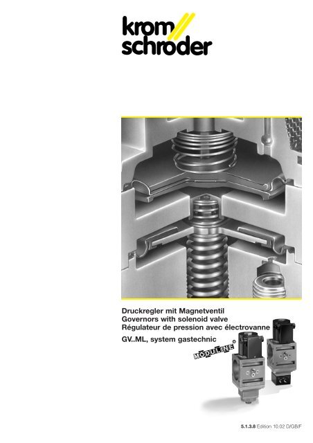
Druckregler mit MagnetventilGovernors with solenoid valveRégulateur de pression avec électrovanne<strong>GV</strong>..<strong>ML</strong>, <strong>system</strong> <strong>gastechnic</strong>5.1.3.8 Edition 10.02 D/GB/F
Kompaktarmaturenstrecken im MODULINE-Programm.Compact valve <strong>system</strong>s in the MODULINE range.Lignes d’appareillages compactes dans le programmeMODULINE.<strong>GV</strong>S..<strong>GV</strong>S..Druckregler mit Magnetventil<strong>GV</strong>..<strong>ML</strong><strong>system</strong> <strong>gastechnic</strong>Universell einsetzbarer Druckregler fürgasförmige Medien mit integriertemSicherheitsventilMit Gasdruckregler Klasse A nach EN 88Hohe RegelgenauigkeitGroßer Ausgangsdruckbereich mit nureiner ReglerfederKeine Ausblaseleitung erforderlichMit Gassicherheitsventil Klasse A nachEN 161Für Taktbetrieb geeignetRobuste Ausführung, lange LebensdauerFlexible Anwendung durch-BauweiseEG - Baumuster geprüft und zertifiziert<strong>GV</strong>I..<strong>GV</strong>IB..Governor withsolenoid valve <strong>GV</strong>..<strong>ML</strong>Governor for gaseous media with integratedsafety valve, with universalrange of applicationsWith gas governor class A to EN 88High regulating precisionBroad outlet pressure range with onlyone governor springNo purge line requiredWith gas safety valve class A toEN 161Suitable for cyclic operationRobust design, long service lifeFlexible application thanks todesignEC type-tested and certified design<strong>GV</strong>R..<strong>GV</strong>RH..Régulateur de pressionavec électrovanne <strong>GV</strong>..<strong>ML</strong>Régulateur de pression universel pourfluides gazeux avec vanne de sécuritéintégréeAvec régulateur de pression gaz classeA selon NE 88Haute précision de régulationLarge plage de pressions de sortieavec un seul ressort de réglageN'exige pas de conduite de purgeAvec vanne de sécurité gaz classe Aselon NE 161Convient pour fonctionnement cycliqueConstruction robuste, grande longévitéGrande souplesse d'utilation grâce àla constructionModèle CEE contrôlé et certifié2
<strong>system</strong> <strong>gastechnic</strong>AnwendungPräzises Regeln des Druckes und sicheresAbsperren der Gas- und Luftzufuhr zuGasbrennern und Gasgeräten. Für denEinsatz in Gasregel- und Sicherheitsstreckenin allen Bereichen der industriellenund gewerblichen Gaswärmeerzeugung.Für die Anwendung z.B. bei Gasmotorensind Antriebe mit 24 V= einsetzbar.Die Druckregler <strong>GV</strong>.. entsprechen denAnforderungen der EN 88, Klasse A.Sie sind Komponenten des MODULINE-Programms. Damit sind sie als Einzelgeräteeinsetzbar und erlauben über dasmodulare Bauprinzip der Durchflußkörperdie individuelle Zusammenstellung vonplatzsparenden Kompaktarmaturenstrekken.Durch die Wahl verschiedener Flanschefür die einzelnen Baugrößen ist die einfacheAnpassung an unterschiedlicheRohrleitungen möglich.Merkmale<strong>GV</strong>S Universell einsetzbarer Druckreglermit hoher Regelgenauigkeit.<strong>GV</strong>D Universell einsetzbarer Druckreglermit gedämpften Anfahrverhalten.<strong>GV</strong>N Nulldruckregler für Gasmotoren.<strong>GV</strong>E Druckregler mit elektrischer Sollwertvorgabe.<strong>GV</strong>I Gleichdruckregler zur Konstanthaltungdes Gas/Luft-Verhältnisses.<strong>GV</strong>IB Gleichdruckregler für Groß-Klein-Zu-Regelung.<strong>GV</strong>R Verhältnisdruckregler zur Konstanthaltungdes Gas/Luft- Verhältnisses.<strong>GV</strong>RH Verhältnisdruckregler zur Konstanthaltungdes Gas/Luft-Mengenverhältnisses.Funktion (Fig. 1)Der Druckregler hält den Ausgangsdruckabhängig von der Einstellung der Sollwertfederbzw. dem Luftsteuerdruck konstant.Wechselnder Gasdurchsatz undschwankender Vordruck beeinflussennicht die Regelgenauigkeit. Eingesetztwird ein Servoreglerbaustein, der denVordruck als Hilfsenergie benutzt.Dadurch werden im Vergleich zu herkömmlichenDruckreglern wesentlich kleinereAbmessungen erzielt.Allgemeine technische DatenGasart: Erdgas, Stadtgas, Flüssiggas(gasförmig) und Luft.Magnetventil: Klasse A, Gruppe 1 nachEN 161.Schließzeit: < 1 s.Schalthäufigkeit: beliebig.Umgebungstemperatur: -20 ... +60° C.Ventilgehäuse: Aluminium.Ventiltellerdichtung: Perbunan.Anschlußflansche mit Innengewinde lieferbar:Rp nach ISO 7-1.ApplicationPrecise governing of the pressure andsafe shut-off of the gas and air supply togas burners and gas appliances. For usein gas control and safety lines in all sectorsof industrial and commercial gasfiredheat generation. Actuators with 24 VDC can be used for application with gasmotors for instance.Governors <strong>GV</strong>.. comply with the requirementsof EN 88 class A. They are componentsof the MODULINE range. Theycan thus be used as individual units andthe modular construction principle of theflow bodies permits space-saving compactvalve <strong>system</strong>s to be assembledindividually.A selection of different flanges for theindividual sizes permits easy adaptationto various types of pipework.UtilisationRégulation précise de la pression et arrêtde sécurité de l'arrivée du gaz et de l'air auxbrûleurs gaz et autres appareils à gaz. Semonte dans les lignes de régulation et desécurité de gaz dans tous les domaines dela production industrielle et commerciale dechaleur par le gaz. On peut utiliser des entraînementsà 24 V= par exemple dans lecas des moteurs à gaz.Les régulateurs de pression <strong>GV</strong>.. satisfontaux spécifications de la norme NE 88, classeA. Ils font partie du programme MODU-LINE. C’est-á-dire que ce sont desappareils autonomes mais que, du fait duprincipe de construction modulaire ducorps, ils peuvent entrer individuellementdans la composition de lignes d’appareillagescompactes et d’encombrement réduit.Un choix de brides pour chacune des différentestailles permet d'adapter lesappareils à des conduites de différentsdiamètres d'une façon simple.Features<strong>GV</strong>S Governor with universal range ofapplication and high regulating precision.<strong>GV</strong>D Governor with universal range ofapplication and damped start-up behaviour.<strong>GV</strong>N Zero pressure governor for gasengines.<strong>GV</strong>E Governor with electrical set-pointadjustment.<strong>GV</strong>I Air/gas ratio control for maintainingthe gas-air ratio constant.<strong>GV</strong>IB Air/gas ratio control for high/low/offcontrol.<strong>GV</strong>R Variable air/gas ratio control formaintaining the gas-air ratio constant.<strong>GV</strong>RH Variable air/gas ratio control formaintaining the gas-air quantity ratio constant.Function (Fig. 1)The governor maintains the outlet pres-Caractéristiques<strong>GV</strong>S Régulateur de pression universel àhaute précision de régulation.<strong>GV</strong>D Régulateur de pression universel àcomportement de démarrage amorti.<strong>GV</strong>N Régulateur à zéro moteurs à gaz.<strong>GV</strong>E Régulateur de pression avec prérégulationélectrique de la valeur de consigne.<strong>GV</strong>I Régulateur de proportion pour lemaintien constant du rapport gaz-air.<strong>GV</strong>IB Régulateur de proportion pourrégulation toute/peu/rien.<strong>GV</strong>R Régulateur de proportion variablepour le maintien constant du rapportgaz-air.<strong>GV</strong>RH Régulateur de proportion variablepour le maintien constant pour le rapportdes débits gaz-air.Fonctionnement (Fig. 1)Le régulateur de pression maintient lapression de sortie constante en fonctiondu réglage du ressort de consigne ou desure constant depending on the setting ofthe setpoint spring or the air control pressure.Changing gas throughput and fluctuatingsupply pressure do not influencethe regulating precision. A servo-governormodule which uses the supply pressureas auxiliary power is used. Thisachieves far smaller dimensions than onconventional governors.General technical dataType of gas: natural gas, town gas, liquefiedpetroleum gas (LPG) and air.Solenoid valve: class A, group 1 to EN161.Closing time: < 1 s.Switching frequency: any.Ambient temperature: -20 to +60° C.Valve body: aluminium.Valve disc seal: Perbunan.Connection flanges with female threadavailable: Rp to ISO 7-1.la pression de commande d'air. Les variationsdu débit de gaz et les fluctuations dela pression amont n'altèrent pas la précisionde la régulation. Dans l'appareil, estincorporé un composant servorégulateurde la pression amont comme énergieauxiliaire, ce qui lui donne des dimensionsbeaucoup plus petites que les régulateursde pression antérieurs.Données techniques généralesType de gaz: gaz naturel, gaz de ville,LPG (sous forme gazeuse) et air.Electrovanne: classe A, groupe 1 selonNE 161.Temps de fermeture: < 1 s.Fréquence de manoeuvre: indifférente.Température ambiante: -20 ... +60° C.Boîtier de vanne: aluminium.Joint de soupape: Perbunan.Nous pouvons livrer des brides de raccordementà filetage intérieur: Rp selonISO 7-1.3
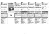
<strong>system</strong> <strong>gastechnic</strong>Fig. 1L1 (+)N (–)Fig. 21 = N (+)2 = L1 (–)Netzspannung:220 bis 240 V, -15/+10%, 50/60 Hz120 V, -15/+10%, 50/60 Hz24 V=, -15/+10%, Gleichspannung.Schutzart: IP 54 nach IEC 529.Leistungsfaktor der Magnetspule:cos ϕ = 1.Einschaltdauer: 100 %.Die elektrische Leistung laut Datentabelleist beim Einschalten und beim Dauerbetriebgleich.Elektrischer Anschluß:Schraubklemmen 2,5 mm 2 (Fig. 2) odermit Gerätestecker nach ISO 4400 (Fig. 3).Meßanschluß Rp 1/8 beidseitig verbundenmit dem Eingang.Meldeschalter (bei <strong>GV</strong>..S/<strong>GV</strong>..G):Diese Geräte sind mit einem Mikroschalterfür die Meldung „geschlossen“ oder„nicht geschlossen“, je nach Verdrahtungder Kontaktfolge (Fig. 4), ausgerüstet undab Werk normgerecht justiert.Mit Gerätestecker nach ISO 4400.Mains voltage:220-240 V, -15/+10%, 50/60 Hz120 V, -15/+10%, 50/60 Hz24 V DC, -15/+10%, DC voltage.Degree of protection provided by enclosure:IP 54 to IEC 529.Power factor of solenoid coil: cos ϕ = 1.Duty cycle: 100%.The electrical power in accordance withthe data table is the same during switchonand during continuous operation.Electrical connection:terminals 2.5 mm 2 (Fig. 2) or with couplerplug to ISO 4400 (Fig. 3).Measuring connection Rp 1/8 connectedto the inlet at both ends.Position indicator (on <strong>GV</strong>..S/<strong>GV</strong>..G):These devices feature a microswitch forsignalling "closed" or "not closed", dependingon wiring of the contact sequence(Fig. 4), and are adjusted in line with applicablestandards at the works.With coupler plug to ISO 4400.Anschlußverschraubung: PG 11, PG 13,5.Kontaktbelastung: 60 - 250 V, 50/60 Hzmax. 2 A (ohmsche Last).Kurzschlußfest: bei Absicherung bis 6,3 Aflink.Bei 24 V= Sonderausführung mit vergoldetenKontakten erforderlich (<strong>GV</strong>..G).Kontaktbelastung bei 24 V: max. 40 mA.EinbauBeim Einbau des Druckreglers in dieRohrleitung Magnetkörper nicht als Hebelbenutzen. Passenden Schraubenschlüsselverwenden. Magnetantriebe nichthängend montieren (Fig. 5).ZubehörZum Schutz des Ventilsitzes und desReglerbausteines muß ein Filter vorgeschaltetwerden. Anschlußflansche mitFilterbaustein und weiteres umfangreichesZubehör siehe Prospekt 5.1.3.20.Cable gland: PG 11, PG 13,5.Contact rating: 60-250 V, 50/60 Hz,max. 2 A (resistive load).Short circuit-proof: if fused up to 6.3 A,quick-acting.At 24 V DC, special version with goldplatedcontacts required (<strong>GV</strong>..G).Contact rating at 24 V: max. 40 mA.InstallationDo not use the solenoid body as a leverwhen installing the governor in the pipework.Use a suitable spanner. Do notmount solenoid actuators suspended(Fig. 5).AccessoriesA suitable filter for protecting the valveseat and the governor module must beconnected upstream. Connection flangeswith filter module and further extensiveaccessories, see brochure 5.1.3.20.312Fig. 3Fig. 4Fig. 5Tension du réseau:220-240 V, -15/+10%, 50/60 Hz120 V, -15/+10%, 50/60 Hz24 V=, -15/+10%, tension continue.Mode de protection: IP 54 selon IEC 529.Facteur de puissance de la bobine:cos ϕ = 1.Temps d'ouverture: 100%.La puissance électrique indiquée autableau de données reste identique audémarrage et en régime stable.Branchement électrique:bornes 2,5 mm 2 (Fig. 2) ou fiche d'appareilselon ISO 4400 (Fig. 3).Raccord de mesure Rp 1/8 raccordé àl'entrée des deux côtés.Indicateur de position (pour <strong>GV</strong>..S/<strong>GV</strong>..G):Ces appareils sont équipés d'un microinterrupteur pour l'indication "fermée" ou"non fermée", selon le câblage de la sériede contacts (Fig. 4) et réglés conformémentaux normes en usine.Fiche d'appareil selon ISO 4400.Filetage des raccords: PG 11, PG 13,5.Charge des contacts: 60-250 V, 50/60 Hzmax. 2 A (charge ohmique).Résistance aux courts-circuits: à actionrapide avec protection jusqu'à 6,3 A.Pour 24 V= il faut un modèle spécial àcontacts d'or (<strong>GV</strong>..G).Charge des contacts à 24 V: max. 40 mA.MontagePour le montage du régulateur sur la conduite,ne pas se servir du bloc magnétiquecomme levier. Utiliser les bonnesclés de serrage. Ne pas monter la commandemagnétique la tête en bas (Fig. 5).AccessoiresMonter impérativement en amont un filtreapproprié pour la protection du siège desoupape et du composant régulateur.Bride de raccordement avec élément defiltre et autres accessoires complets, voirprospectus 5.1.3.20.4
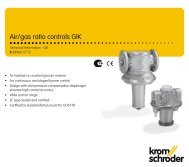
<strong>system</strong> <strong>gastechnic</strong>Druckreglermit Magnetventil <strong>GV</strong>S..<strong>ML</strong>Zur Sicherung und Regelung des Gasdruckesin Gaseingangs- und Brennerstrecken.Funktion: Nach Öffnen des Magnetventilshält der Druckregler den eingestelltenAusgangsdruck konstant. Nach demSchließen sperrt das Magnetventil dasGas sicher ab (Fig. 6).Technische DatenEingangsdruck p e : max. 200 (100) mbar.Ausgangsdruck p a : 2 bis 100 (96) mbarmit nur einer Feder einstellbar,werksseitige Einstellung: ca. 10 mbar.Druckregler entsprechend EN 88, KlasseA sowie DIN 3380, RG 10.<strong>GV</strong>SD<strong>GV</strong>S..Np a [mbar]AKTFL FB<strong>GV</strong>SFLGovernorwith solenoid valve <strong>GV</strong>S..<strong>ML</strong>For safeguarding and governing thepressure in gas inlet and burner lines.Function: when the solenoid valveopens, the governor maintains the setoutlet pressure constant. After closing,the solenoid valve reliably shuts off thegas supply (Fig. 6).Technical dataInlet pressure p e : max. 200 (100) mbar.Outlet pressure p a : 2 to 100 (96) mbarcan be set with only one spring,works setting: approx. 10 mbar.Governor to EN 88, class A and DIN3380, RG 10.t [s]Fig. 6H4H2Pg 11T1T2ERégulateur de pressionavec électrovanne <strong>GV</strong>S..<strong>ML</strong>Pour la protection et la régulation de lapression du gaz dans les lignes d'entréede gaz et lignes de brûleurs.Fonctionnement: Après ouverture del'électrovanne, le régulateur de pressionmaintient la pression de sortie réglée àun niveau constant. Après la fermeture,l'électrovanne ferme l'arrivée de gaz entoute sécurité (Fig. 6).Données techniquesPression d’entréep e : max. 200 (100) mbars.Pression de sortie p a : 2 à 100 (96)mbars, réglable avec un seul ressort,réglage d'usine: environ 10 mbars.Régulateur conforme à NE 88, classe A,ainsi que DIN 3380, RG 10.H1H3FLTyp DN Anschlußflansch Baumaße kvs P GewichtType Flange Dimensions 220 V 240 V WeightRaccord 110 V PoidsL H1 H2 H3 H4 T1 T2 E F 24 Vmm mm mm mm mm mm mm mm mm m 3 /h VA/W VA/W kg<strong>GV</strong>S 115/12.. 12 Rp 3/8, 1/2, 3/4, 1 60 85 109 30 162 35 49 56 25 2,4 32 38 1,5<strong>GV</strong>S 115.. 15 Rp 3/8, 1/2, 3/4, 1 60 85 109 30 162 35 49 56 25 5,5 32 38 1,5<strong>GV</strong>S 125.. 25 Rp 3/8, 1/2, 3/4, 1 60 85 109 30 162 35 49 61 25 9 36 42 1,9<strong>GV</strong>S 232.. 32 Rp 1, 1 1/2 96 125 134 47 185 51 65 66 34 20 36 42 3,3<strong>GV</strong>S 350.. 50 Rp 1 1/2, 2 130 160 230 62 285 70 84 82 42 39 73 86 7,35
<strong>system</strong> <strong>gastechnic</strong><strong>GV</strong>DDruckreglermit Magnetventil <strong>GV</strong>D..<strong>ML</strong>Zur Sicherung und Regelung des Gasdruckesin Brennerstrecken.Funktion: Nach Öffnen des Magnetventilssteigt der Ausgangsdruck in zwei Stufenauf den eingestellten Wert. Gasbrennerstarten auf diese Weise gedämpft.Nach Schließen des Magnetventils wirddas Gas sicher abgesperrt.Der Startgasdruck kann eingestellt werden.Nach ca. 3 bis 10 s Haltezeit erfolgtein gedämpfter Druckanstieg von p s aufp a (Fig. 7).Für die Reproduzierbarkeit des Startgasdruckesist zwischen zwei Schaltungeneine Wartezeit von min. 30 s erforderlich.Technische DatenEingangsdruck p e : max. 100 mbar.Startgasdruck p s : 2,5 bis 10 mbar.Ausgangsdruck p a : 5 bis 50 mbar,werksseitige Einstellung: ca. 10 mbar.Druckregler entsprechend EN 88, KlasseA sowie DIN 3380, RG10.p a [mbar]AKTDGFL FB<strong>GV</strong>DVS..NFLGovernorwith solenoid valve <strong>GV</strong>D..<strong>ML</strong>For safeguarding and governing the gaspressure in burner lines.Function: when the solenoid valveopens, the outlet pressure increases intwo steps to the set value. Gas burnersstart undamped in this manner. After thesolenoid valve closes, the gas is shut offreliably.The start gas pressure can be set. Afterapprox. 3 to 10 s holding time, the pressureincreases damped from p s to p a(Fig. 7).A waiting time of min. 30 s is required betweentwo switching operations in orderto achieve reproducibility of the start gaspressure.Technical dataInlet pressure p e : max. 100 mbar.Start gas pressure p s : 2.5 to 10 mbar.Outlet pressure p a : 5 to 50 mbar,works setting: approx. 10 mbar.Governor to EN 88, class A and DIN3380, RG 10.H4H2Pg 11T1T2Et [s]Fig. 7Régulateur de pressionavec électrovanne <strong>GV</strong>D..<strong>ML</strong>Pour la protection et la régulation de lapression du gaz dans les lignes debrûleur.Fonctionnement: Après ouverture del'électrovanne, la pression de sorties'élève en deux paliers pour atteindre lavaleur réglée. De cette façon, les brûleursgaz démarrent avec amortissement.Après fermeture de l'électrovanne, le gazest arrêté en toute sécurité.On peut régler la pression de gaz dedémarrage. Après un temps de maintiend'environ 3 à 10 s, se produit une élévationamortie de la pression de p s à p a (Fig. 7).Pour la reproductibilité de la pression dugaz de démarrage, il faut respecter untemps d'attente de 30 s au minimum entredeux commutations.Données techniquesPression d’entrée p e : max. 100 mbars.Pression de gaz de démarrage p s : 2,5 à10 mbars.Pression de sortie p a : 5 à 50 mbars,réglage d'usine: environ 10 mbars.Régulateur conforme à NE 88, classe A,ainsi que DIN 3380, RG 10.H1H3FLSTTyp DN Anschlußflansch Baumaße kvs P GewichtType Flange Dimensions 220 V 240 V WeightRaccord 110 V PoidsL H1 H2 H3 H4 T1 T2 E F 24 Vmm mm mm mm mm mm mm mm mm m 3 /h VA/W VA/W kg<strong>GV</strong>D 115/12.. 12 Rp 3/8, 1/2, 3/4, 1 60 78 109 30 162 35 49 56 25 2,4 32 38 1,5<strong>GV</strong>D 115.. 15 Rp 3/8, 1/2, 3/4, 1 60 78 109 30 162 35 49 56 25 5,5 32 38 1,5<strong>GV</strong>D 125.. 25 Rp 3/8, 1/2, 3/4, 1 60 78 109 30 162 35 49 61 25 9 36 42 1,9<strong>GV</strong>D 232.. 32 Rp 1, 1 1/2 96 118 134 47 185 51 65 66 34 20 36 42 3,3<strong>GV</strong>D 350.. 50 Rp 1 1/2, 2 130 153 230 62 285 70 84 82 42 39 73 86 7,36
<strong>system</strong> <strong>gastechnic</strong><strong>GV</strong>NNulldruckreglermit Magnetventil <strong>GV</strong>N..<strong>ML</strong>Zur Sicherung und Regelung des Gasdruckesin Gasregelstrecken für Gasmotoren.Funktion: Nach Öffnen des Magnetventilshält der Druckregler den eingestelltenAusgangsdruck konstant (Fig. 8). Nachdem Schließen sperrt das Magnetventildas Gas sicher ab.Als Korrekturgröße kann der Luftansaugdruckauf den Regler aufgeschaltet werden.Technische DatenEingangsdruck: max. 100 mbar.Ausgangsdruck: -10 ... 10 mbarAnschluß der Impulsleitung: Klemmringverschraubungfür Rohr 6 x 1 mm.D<strong>GV</strong>S..Np a [mbar]AKTFL FB<strong>GV</strong>NFLZero-pressure governorwith solenoid valve <strong>GV</strong>N..<strong>ML</strong>For safeguarding and controlling the gaspressure in gas control <strong>system</strong>s for gasengines.Function: The governor maintains the setoutlet pressure constant after opening thesolenoid valve (Fig. 8). When closed, thesolenoid valve shuts off the gas supplysecurely. The air suction pressure line canbe connected to the governor as correctivevariable.Technical dataInlet pressure: max. 100 mbar.Outlet pressure: -10 ... 10 mbarImpulse line connection: compression fittingfor 6 x 1 tube.t [s]Fig. 8H4H2Pg 11T1T2ERégulateur à zéroavec électrovanne <strong>GV</strong>N..<strong>ML</strong>Pour la sécurité et la régulation de pressiongaz dans les lignes de régulation dugaz des moteurs à gaz.Fonctionnement: Après l’ouverture del’électrovanne, le régulateur de pressionmaintien la pression de sortie réglée constante(Fig. 8). Après sa fermeture, l’électrovannearrête le débit de gaz avec sécurité.Comme valeur corrective la ligne depression de succion air peut être connectéeau régulateur.Caractéristiques techniquesPression d’entrée: max. 100 mbars.Pression de sortie: -10 ... 10 mbarsConnexion de la ligne d’impulsion: connexionpar anneau de serrage pour tube6 x 1.H1H3FLTyp DN Anschlußflansch Baumaße kvs P GewichtType Flange Dimensions 220 V 240 V WeightRaccord 110 V PoidsL H1 H2 H3 H4 T1 T2 E F 24 Vmm mm mm mm mm mm mm mm mm m 3 /h VA/W VA/W kg<strong>GV</strong>N 115/12.. 12 Rp 3/8, 1/2, 3/4, 1 60 99 109 30 162 35 49 56 25 2,4 32 38 1,5<strong>GV</strong>N 115.. 15 Rp 3/8, 1/2, 3/4, 1 60 99 109 30 162 35 49 56 25 5,5 32 38 1,5<strong>GV</strong>N 125.. 25 Rp 3/8, 1/2, 3/4, 1 60 99 109 30 162 35 49 61 25 9 36 42 1,9<strong>GV</strong>N 232.. 32 Rp 1, 1 1/2 96 139 134 47 185 51 65 66 34 20 36 42 3,3<strong>GV</strong>N 350.. 15 Rp 1 1/2, 2 130 174 230 62 285 70 84 82 42 39 73 86 7,37
<strong>system</strong> <strong>gastechnic</strong><strong>GV</strong>EDruckreglermit Magnetventil <strong>GV</strong>E..<strong>ML</strong>Zur Sicherung und Regelung des Gasdruckesund zur Leistungsverstellung inBrennerstrecken. Auch zur Lambdaregelungeinsetzbar.Funktion: Nach Öffnen des Magnetventilskann der Sollwert elektrisch eingestelltwerden. Der Ausgangsdruck wird entsprechendkonstant gehalten.Nach dem Schließen sperrt das Magnetventildas Gas sicher ab.Technische DatenEingangsdruck: max. 100 mbar.Steuersignal: 0(4) ... 20 mAAusgangsdruck: 2 ... 15 mbarEinstellbereich bei Kleinlast:-5 bis +5 mbar.D<strong>GV</strong>S..NAKTFL FB<strong>GV</strong>EFLGovernorwith solenoid valve <strong>GV</strong>E..<strong>ML</strong>constant. When closed, the solenoid valveshuts off the gas supply securely.p a [mbar]For safeguarding and controlling the gaspressure in and adjusting the output ofburners lines; can also be used for lambdacontrol.Function: The set-point can be adjustedelectrically after opening the solenoidvalve. The outlet pressure is maintainedTechnical dataInlet pressure: max. 100 mbar.Control signal: 0(4) ... 20 mAOutlet pressure: 2 ... 15 mbarAdjusting range with low fire:-5 to +5 mbar.I[mA]Fig. 9H4H2T1T2EPg 11Régulateur de pressionavec électrovanne <strong>GV</strong>E..<strong>ML</strong>Pour la sécurité et la régulation de pressiongaz et l’ajustement de puissancedans les lignes de brûleurs; applicationpossible pour l’ajustement lambda.Fonctionnement: Après l’ouverture del’électrovanne, la valeur de consigne peutêtre réglée électriquement. La pressionde sortie est donc maintenue constanteAprès sa fermeturé, l’électrovanne arrêtele debit de gaz avec sécurité.Caractéristiques techniquesPression d’entrée: max. 100 mbars.Signal de commande: 0(4) ... 20 mAPression de sortie: 2 ... 15 mbarsPlage de réglage avec débit minimum:-5 à +5 mbars.H3H1FLTyp DN Anschlußflansch Baumaße kvs P GewichtType Flange Dimensions 220 V 240 V WeightRaccord 110 V PoidsL H1 H2 H3 H4 T1 T2 E F 24 Vmm mm mm mm mm mm mm mm mm m 3 /h VA/W VA/W kg<strong>GV</strong>E 115/12.. 12 Rp 3/8, 1/2, 3/4, 1 60 113 109 30 162 35 49 56 25 2,4 32 38 1,8<strong>GV</strong>E 115.. 15 Rp 3/8, 1/2, 3/4, 1 60 113 109 30 162 35 49 56 25 5,5 32 38 1,8<strong>GV</strong>E 125.. 25 Rp 3/8, 1/2, 3/4, 1 60 113 109 30 162 35 49 61 25 9 36 42 2,2<strong>GV</strong>E 232.. 32 Rp 1, 1 1/2 96 153 134 47 185 51 65 66 34 20 36 42 3,6<strong>GV</strong>E 350.. 50 Rp 1 1/2, 2 130 193 230 62 285 70 84 82 42 39 73 86 7,78
<strong>system</strong> <strong>gastechnic</strong><strong>GV</strong>IGleichdruckreglermit Magnetventil <strong>GV</strong>I..<strong>ML</strong>Zur Absicherung von stufenlos geregeltenBrennern mit pneumatischem Verbundzwischen Gas und Luft.Funktion: Nach Öffnen des Magnetventilshält der Druckregler den Gasausgangsdruckabhängig vom Luftsteuerdruck konstant(Fig. 10). Im Kleinlastbereich kanndas Gas/Luftgemisch durch Justieren derReglerfeder verändert werden. Das Einstellender Vollast erfolgt über Drosselnam Brenner.Technische DatenEingangsdruck p e : max. 200 (100)mbar.Luftsteuerdruck p L : 0,5 bis 120 (90) mbar.Ausgangsdruck p G : 0,2 bis 120 (90) mbar.Einstellbereich bei Kleinlast:-3 bis +8 mbar.Übersetzungsverhältnis: 1:1.Der Eingangsdruck muß immer höher alsder Luftsteuerdruck sein.Anschluß der Impulsleitung: Klemmringverschraubungfür Rohr 6 x 1 mm.DGBVp G [mbar]AKTDGFL FB <strong>GV</strong>IMDK+GT 31VS..LDK+N-NFLAir/gas ratio controlwith solenoid valve <strong>GV</strong>I..<strong>ML</strong>For safeguarding steplessly controlledburners with pneumatic link between gasand air.Function: when the solenoid valve opens,the governor maintains the gas outletpressure constant dependent on the aircontrol pressure (Fig. 10). In the minimumflow range, the gas-air mixture can bevaried by adjusting the governor spring.High fire is set by means of restrictorson the burner.Technical dataInlet pressure p e : max. 200 (100) mbar.Air control pressure p L : 0.5 to 120 (90) mbar.Outlet pressure p G : 0.2 to 120 (90) mbar.Range of adjustment at minimum flow:-3 to +8 mbar.Transmission ratio: 1:1.The inlet pressure must always be higherthan the air control pressure.Connection of the impulse line: compressionfitting for pipe 6 x 1 mm.H4H2Pg 11T1T2p L [mbar]Fig. 10ERégulateur de proportionavec électrovanne <strong>GV</strong>I..<strong>ML</strong>Pour la protection de brûleurs à régulationcontinue avec liaison pneumatique entregaz et air.Fonctionnement: Après ouverture del'électrovanne, le régulateur de pressionmaintient la pression de sortie du gazconstante en fonction de la pression decommande d'air (Fig. 10). Dans la plagede débit mini, le mélange gaz-air peut êtremodifié par réglage du ressort du régulateur.Le réglage du débit maxi s'effectueau moyen d'étranglements sur le brûleur.Données techniquesPression d’entrée p e : max. 200 (100) mbars.Pression de commande d'air p L :0,5 à 120 (90) mbars.Pression de sortie p G :0,2 à 120 (90) mbars.Plage de réglage à débit mini:-3 à +8 mbars.Rapport de transformation: 1:1.La pression d'entrée doit toujours êtresupérieure à la pression de commanded'air.Raccordement de la ligne d'impulsions:filetage de la bague de serrage pourtubes 6 x 1 mm.H1H3FLTyp DN Anschlußflansch Baumaße kvs P GewichtType Flange Dimensions 220 V 240 V WeightRaccord 110 V PoidsL H1 H2 H3 H4 T1 T2 E F 24 Vmm mm mm mm mm mm mm mm mm m 3 /h VA/W VA/W kg<strong>GV</strong>I 115/12.. 12 Rp 3/8, 1/2, 3/4, 1 60 99 109 30 162 35 49 56 25 2,4 32 38 1,5<strong>GV</strong>I 115.. 15 Rp 3/8, 1/2, 3/4, 1 60 99 109 30 162 35 49 56 25 5,5 32 38 1,5<strong>GV</strong>I 125.. 25 Rp 3/8, 1/2, 3/4, 1 60 99 109 30 162 35 49 61 25 9 36 42 1,9<strong>GV</strong>I 232.. 32 Rp 1, 1 1/2 96 139 134 47 185 51 65 66 34 20 36 42 3,3<strong>GV</strong>I 350.. 50 Rp 1 1/2, 2 130 174 230 62 285 70 84 82 42 39 73 86 7,39
<strong>system</strong> <strong>gastechnic</strong>Gleichdruckreglermit Magnetventil <strong>GV</strong>IB..<strong>ML</strong>Zur Absicherung von impulsgeregeltenBrennern mit pneumatischem Verbundzwischen Gas und Luft.Funktion: Für die Kleinlast wird nur dasGasmagnetventil geöffnet. Die minimaleGas- und Luftmenge gelangen über zweiBypässe zum Brenner. Der Bypass am<strong>GV</strong>IB (auf Wunsch mit fester Düse) isteinstellbar. Bei Wärmeanforderung wirddas Luftstellglied geöffnet. Über dieImpulsleitung bewirkt der steigendeLuftsteuerdruck am Gleichdruckreglereinen proportionalen Gasausgangsdruck(Fig. 11).Technische DatenEingangsdruck p e : max. 200 (100) mbar.Luftsteuerdruck p L : 0,5 bis 120 (90) mbar.Ausgangsdruck p G : 0,2 bis 120 (90) mbar.Übersetzungsverhältnis: 1:1.Anschluß der Impulsleitung: Klemmringverschraubungfür Rohr 6 x 1 mm.<strong>GV</strong>IBAKTDGp G [mbar]DGFL FB <strong>GV</strong>IBMK..RBVVS..L FLDKAir/gas ratio controlwith solenoid valve <strong>GV</strong>IB..<strong>ML</strong>For safeguarding impulse-controlledburners with pneumatic link between gasand air.Function: only the solenoid valve for gasis opened for minimum flow. The minimumgas and air quantities are suppliedto the burner via two bypasses. Thebypass on the <strong>GV</strong>IB (non-adjustablenozzle on request) is adjustable. Whenheat demand occurs, the air valve is opened.The increasing air control pressureon the air/gas ratio control results in aproportional gas outlet pressure (Fig. 11)via the impulse line.Technical dataInlet pressure p e : max. 200 (100) mbar.Air control pressurep L : 0.5 to 120 (90) mbar.Outlet pressure p G : 0.2 to 120 (90) mbar.Transmission ratio: 1:1.Connection of the impulse line: compressionfitting for pipe 6 x 1 mm.Régulateur de proportionavec électrovanne <strong>GV</strong>IB..<strong>ML</strong>Pour la protection de brûleurs à régulationpar impulsions avec liaison pneumatiqueentre gaz et air.Fonctionnement: Pour le débit minimum,on n'ouvre que l'électrovanne à gaz. Lesdébits mini de gaz et d'air parviennentaux brûleurs par deux bypasses. Lebypass du <strong>GV</strong>IB (sur demande avec orificeà débit constant) est réglable. Encas de besoin de chaleur, la vanne deréglage air s'ouvre. La pression de commanded'air croissante présente sur lerégulateur de proportion détermine, parla ligne d'impulsions, une pression desortie de gaz proportionnelle (Fig. 11).Données techniquesPression d’entrée p e : max. 200 (100) mbars.Pression de commande d'airp L : 0,5 à 120 (90) mbars.Pression de sortie p G : 0,2 à120 (90) mbars.Rapport de transformation: 1:1.Raccord de la ligne d'impulsions:filetage de bague de serrage pour tubes6 x 1 mm.H4H2T2Pg 11T1p L [mbar]Fig. 11EBypass <strong>GV</strong>IBEingangsdruck, Inlet pressure, Pression amont p e [mbar]100806050403020108654321 10,04 0,05 0,08 0,1 0,2 0,3 0,4 0,5 0,6 0,8 12 320,05 0,08 0,1 0,2 0,3 0,4 0,5 0,6 0,8 12 3 430,03 0,04 0,05 0,08 0,1 0,2 0,3 0,4 0,5 0,6 0,8 1 240,03 0,04 0,05 0,08 0,1 0,2 0,3 0,4 0,5 0,6 0,8 1 2V’ [m 3 /h (n)]1 = Erdgas (N) dv = 0,62 2 = Stadtgas (S) dv = 0,45 3 = Fl ssiggas (F) dv = 1,56 4 = Luft (L) dv = 1,00Natural gas sg = 0.62 Town gas sg = 0.45 LPGsg = 1.56 Air sg = 1.00Gaz Naturel dv = 0,62 Gaz de Ville dv = 0,45 Gaz de p trole liqu fie dv = 1,56 Air(L) dv = 1,001,2 mm1,5 mm1,8 mm2,0 mm2,5 mm3,0 mm4,0 mmH3H1FLTyp DN Anschlußflansch Baumaße kvs P GewichtType Flange Dimensions 220 V 240 V WeightRaccord 110 V PoidsL H1 H2 H3 H4 T1 T2 E F 24 Vmm mm mm mm mm mm mm mm mm m 3 /h VA/W VA/W kg<strong>GV</strong>IB 115/12.. 12 Rp 3/8, 1/2, 3/4, 1 60 99 109 30 162 60 49 56 25 2,4 36 42 1,8<strong>GV</strong>IB 115.. 15 Rp 3/8, 1/2, 3/4, 1 60 99 109 30 162 60 49 56 25 5,5 36 42 1,8<strong>GV</strong>IB 125.. 25 Rp 3/8, 1/2, 3/4, 1 60 99 109 30 162 60 49 61 25 9 40 46 2,2<strong>GV</strong>IB 232.. 32 Rp 1, 1 1/2 96 139 134 47 185 78 65 66 34 20 40 46 3,7<strong>GV</strong>IB 350.. 50 Rp 1 1/2, 2 130 174 230 62 285 70 84 82 42 39 73 86 7,310
<strong>system</strong> <strong>gastechnic</strong><strong>GV</strong>RVerhältnisdruckreglermit Magnetventil <strong>GV</strong>R..<strong>ML</strong>Zur Absicherung von stufenlos geregeltenBrennern mit pneumatischem Verbundzwischen Gas und Luft. EinstellbaresÜbersetzungsverhältnis zur Steuerungeines hohen Gasausgangsdruckes mitniedrigem Luftdruck.Funktion: Nach Öffnen des Magnetventilswird der Gasausgangsdruck geregelt.Dieser folgt dem Luftsteuerdruck. DasVerhältnis V zwischen Gas- und Luftdruckist einstellbar, um mit einem niedrigenLuftsteuerdruck p L einen hohen Gasausgangsdruckp G zu erreichen. Der Feuerraumdruckp F kann korrigierend aufgeschaltetwerden (Fig.12). Im Kleinlastbereichdes Brenners wird das Gas/Luftgemischdurch Justieren der Einstellschraube Neingestellt. Bei Vollast wird das Übersetzungsverhältnismit der EinstellschraubeV so verändert, daß die gewünschten Abgasanalysewerteerzielt werden (Fig. 13). DGBVAKTFL FB <strong>GV</strong>RVS..LFLp FDGMDK+GT 31DKp G [mbar]+V-VFig.12+N-NVariable air/gas ratio controlwith solenoid valve <strong>GV</strong>R..<strong>ML</strong>For safeguarding steplessly controlledburners with pneumatic link between gasand air. Adjustable transmission ratio forcontrol of a high gas outlet pressure withlow air pressure.Function: when the solenoid valveopens, the gas outlet pressure is controlled.The gas outlet pressure followsthe air control pressure. The ratio V betweengas and air pressure is adjustablein order to achieve a high gas outlet pressurep G with a low air control pressure p L .Corrective feedforward control (Fig. 12) isavailable for the combustion chamberpressure p F . In the min.-flow range of theburner, the gas-air mixture is set by adjustingthe setscrew N. At high fire, thetransmission ratio is adjusted with the setscrewV so that the required flue gasanalysis values are achieved (Fig. 13). ∆p L [mbar]Fig.13Régulateur de proportionvariable avec électrovanne<strong>GV</strong>R..<strong>ML</strong>Pour la protection de brûleurs à régulationcontinue avec liaison pneumatique entregaz et air. Rapport de transformationréglable pour la commande d'une hautepression de sortie du gaz avec une faiblepression d'air.Fonctionnement: Après ouverture del'électrovanne, la pression de sortie dugaz est régulée. Cette pression suit lapression de commande d'air. Le rapport Ventre les pressions de gaz et d'air estréglable pour permettre d'obtenir unehaute pression de sortie de gaz p G avecune basse pression de commande d'airp L . la pression du foyer p F peut être élevéeen correction (Fig. 12). Dans la plagedes débits mini du brûleur, le mélangegaz-air est réglé par action sur la vis deréglage N. Au débit maximum, on modifiele rapport de transformation à l'aide de lavis de réglage V pour obtenir les valeursdésirées d'analyse des gaz d'échappement(Fig. 13).11
<strong>system</strong> <strong>gastechnic</strong>Technische DatenEingangsdruck p e : max. 100 mbar.Luftsteuerdruck p L : 0,4 bis 30 mbar.Ausgangsdruck p G : 0,4 bis 50 mbar.zulässiger Feuerraumdruck p F :-2 bis +20 mbar.Einstellbereich Kleinlast N:-1,5 .. +1,5 mbar.Übersetzungsverhältnis:V = p G /p L = 0,7:1 bis 7:1.Ausgangsdruck ohne Anschluß des Feuerraumdruckesp G = V * p L + N.Ausgangsdruck mit Anschluß des Feuerraumdruckes(p G - p F ) = V * (p L - p F ) + N.Projektierungshinweis: Rohrinnendurchmesserfür Impulsleitungen p L undp F > 2 mm. Damit der Druckregler beiLastwechsel schnell genug reagierenkann, sollte die Impulsleitung für p L möglichstkurz sein. Die Impulsleitung für denFeuerraumdruck p F muß so verlegt werden,daß kein Kondensat in den Druckreglergelangen kann, sondern in denFeuerraum zurückfließt.Technical dataInlet pressure p e : max. 100 mbar.Air control pressure p L : 0.4 to 30 mbar.Outlet pressure p G : 0.4 to 50 mbar.Permitted combustion chamber pressurep F : -2 to +20 mbar.Range of adjustment min. flow N:-1.5 to +1.5 mbar.Transmission ratioV = p G /p L = 0.7:1 to 7:1.Outlet pressure without connection of thecombustion chamber pressurep G = V * p L + N.Outlet pressure with connection of thecombustion chamber pressure(p G - p F ) = V * (p L - p F ) + N.Note on planning: pipe inside diameterfor impulse lines p L and p F > 2 mm. Inorder for the governor to respond quicklyenough in the case of a load change, theimpulse line for p L should be as short aspossible. The impulse line for the combustionchamber pressure p F must belaid so as to prevent condensate reachingthe governor and so that the condensateflows back into the combustionchamber.H4H2Pg 11T1T2EDonnées techniquesPression d’entrée p e : max. 100 mbars.Pression de commande d'air p L :0,4 à 30 mbars.Pression de sortie p G : 0,4 à 50 mbars.Pression admissible dans le foyer p F :-2 à +20 mbars.Plage de réglage débit minimum N:-1,5 à +1,5 mbars.Rapport de transformationV = p G /p L = 0,7:1 à 7:1.Pression de sortie sans raccordement dela pression du foyer p G = V * p L +N.Pression de sortie avec raccordement dela pression du foyer(p G - p F ) = V * (p L - p F ) + N.Instructions pour l'étude: Diamètre intérieurpour lignes d'impulsions p L et p F> 2 mm. Maintenir la ligne d'impulsionspour p L aussi courte que possible afinque le régulateur puisse réagir assez viteaux variations du débit. La ligne d'impulsionspour la pression du foyer p F doitêtre posée de manière que les condensatsne puissent pas atteindre le régulateurmais qu'ils refluent vers le foyer.H1H3FLTyp DN Anschlußflansch Baumaße kvs P GewichtType Flange Dimensions 220 V 240 V WeightRaccord 110 V PoidsL H1 H2 H3 H4 T1 T2 E F 24 Vmm mm mm mm mm mm mm mm mm m 3 /h VA/W VA/W kg<strong>GV</strong>R 115/12.. 12 Rp 3/8, 1/2, 3/4, 1 60 78 109 30 162 35 49 56 25 2,4 32 38 1,6<strong>GV</strong>R 115.. 15 Rp 3/8, 1/2, 3/4, 1 60 78 109 30 162 35 49 56 25 5,5 32 38 1,6<strong>GV</strong>R 125.. 25 Rp 3/8, 1/2, 3/4, 1 60 78 109 30 162 35 49 61 25 9 36 42 1,9<strong>GV</strong>R 232.. 32 Rp 1, 1 1/2 96 118 134 47 185 51 65 66 34 20 36 42 3,4<strong>GV</strong>R 350.. 50 Rp 1 1/2, 2 130 153 230 62 285 70 84 82 42 39 73 86 7,412
<strong>system</strong> <strong>gastechnic</strong><strong>GV</strong>RHVerhältnisdruckreglermit Magnetventil <strong>GV</strong>RH..<strong>ML</strong>Zur Absicherung von stufenlos geregeltenRekuperatorbrennern mit pneumatischemVerbund zwischen Gas und Luft,sowie Einsatz in Anlagen, in denen sichdie Druckverhältnisse im Brenner und imFeuerraum bei Leistungsänderungennicht linear ändern.Funktion: Nach Öffnen des Magnetventilswird der Gasvolumenstrom geregelt.Dieser folgt dem Luftdifferenzdruck, deran einer Meßblende gemessen wird. DasVerhältnis zwischen Gasmenge und Luftmengebleibt konstant. Im Kleinlastbereichist es vielfach erforderlich, daß aufgrundder kleineren Mischenergie mitetwas Luftüberschuß gefahren wird, umdas Gas optimal zu verbrennen. DieseEinstellung erfolgt mit Hilfe der Reglerfeder(Fig. 14). Das Differenzdruckverhältniszwischen Gas und Luft beträgt 1:1.Technische DatenEingangsdruck p e : max. 200 mbar.Luftsteuerdruck p L+ : 0,2 bis 100 mbar.Luftsteuerdruck p L- : 0,2 bis 100 mbar.Differenzdruck Luft (p L+ - p L- ):0,3 bis 30 mbar.Differenzdruck Gas (p G+ - p G- ):<strong>GV</strong>RH..F1: 0,3 bis 30 mbar.Einstellbereich Kleinlast N: -5 bis +5 mbar.Anschluss der Impulsleitungen: Klemmringverschraubungfür Rohr 6 x 1 mm.p G [mbar]AKTDGDGFL FB<strong>GV</strong>RHMDK+GT 31BV FLVS..LDK+N-NVariable air/gas ratio controlwith solenoid valve <strong>GV</strong>RH..<strong>ML</strong>For safeguarding steplessly controlledrecuperative burners with pneumatic linkbetween gas and air and for use in<strong>system</strong>s in which the pressure ratios inthe burner and combustion chamber donot change in linear fashion when subjectto power variations.Function: when the solenoid valveopens, the gas flow rate is controlled. Thegas flow rate follows the differential airpressure which is measured at a measuringorifice. The ratio between gas quantityand air quantity remains constant. Inthe min.-flow range, it is necessary, inmany cases, to operate with slightlyexcess air owing to the lower mixing energyin order to achieve optimum combustionof the gas. This setting is performedwith the aid of the governor spring(Fig.14). The differential pressure ratiobetween gas and air is 1:1.Technical dataInlet pressure p e : max. 200 mbar.Air control pressure p L+ : 0.2 to 100 mbar.Air control pressure p L- : 0.2 to 100 mbar.Differential pressure air (p L+ - p L- ):0.3 to 30 mbar.Differential pressure gas (p G+ - p G- ):<strong>GV</strong>RH..F1: 0.3 to 30 mbar.Range of adjustment min. flow N:-5 to +5 mbar.Connection of the impulse lines: compressionfitting for pipe 6 x 1 mm.H4H2Pg 11T1T2∆p L [mbar]Fig.14ERégulateur de proportionvariable avec électrovanne<strong>GV</strong>RH..<strong>ML</strong>Pour la protection de brûleurs à récupérateurà régulation continue, avec liaisonpneumatique entre le gaz et l'air et pourl'utilisation dans les installations où lesrapports des pressions du brûleur et dufoyer varient de façon non linéaire en présencede variations de puissance.Fonctionnement: Après ouverture del'électrovanne, le débit de gaz est régulé.Ce débit suit la pression différentielle d'airqui est mesurée sur un diaphragme demesure. Le rapport entre le débit de gazet le débit d'air reste constant. Dans laplage des débits mini, il est fréquemmentnécessaire de travailler avec un légerexcès d'air, en raison de la faible énergiedisponible pour le mélangeage, afin d'obtenirune combustion optimale du gaz. Ceréglage s'effectue à l'aide du ressort durégulateur (Fig. 14). Le rapport de la pressiondifférentielle entre le gaz et l’air est de1/1.Données techniquesPression d’entrée p e : max. 200 mbarsPression de commande d'air p L+ :0,2 à 100 mbars.Pression de commande d'air p L- :0,2 à 100 mbars.Pression différentielle air (p L+ - p L- ):0,3 à 30 mbars.Pression différentielle gaz (p G+ - p G- ):<strong>GV</strong>RH..F1: 0,3 à 30 mbars.Plage de réglage débit mini N:-5 à +5 mbarsRaccordement des lignes d'impulsions:filetage de la bague de serrage pour tube6 x 1 mm.H1H3FLTyp DN Anschlußflansch Baumaße kvs P GewichtType Flange Dimensions 220 V 240 V WeightRaccord 110 V PoidsL H1 H2 H3 H4 T1 T2 E F 24 Vmm mm mm mm mm mm mm mm mm m 3 /h VA/W VA/W kg<strong>GV</strong>RH 115/12.. 15 Rp 3/8, 1/2, 3/4, 1 60 111 109 30 162 35 49 56 25 2,4 32 38 1,7<strong>GV</strong>RH 115.. 15 Rp 3/8, 1/2, 3/4, 1 60 111 109 30 162 35 49 56 25 5,5 32 38 1,7<strong>GV</strong>RH 125.. 25 Rp 3/8, 1/2, 3/4, 1 60 111 109 30 162 35 49 61 25 9 36 42 2,0<strong>GV</strong>RH 232.. 32 Rp 1, 1 1/2 96 151 134 47 185 51 65 66 34 20 36 42 3,5<strong>GV</strong>RH 350.. 50 Rp 1 1/2, 2 130 186 230 62 285 70 84 82 42 39 67 75 7,513
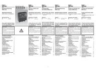
G. Kromschröder AG Tel. ++49 (0)5 41/12 14-0 · Fax -3 70Postfach 2809 info@kromschroeder.comD-49018 Osnabrück www.kromschroeder.deVolumenstromFlow RateCaractéristiques de DébitDie Durchflußkennlinien wurden mitden angegebenen Flanschen ohneSieb gemessen. Bei Kombination vonzwei und mehr Armaturen verringertsich der Druckverlust jederEinzelarmatur um ca. 5%.The flow lines were measured withthe indicated flanges without a strainer.When combining two or more fittingsthe pressure drop in each fittingis reduced by approx. 5%.Les courbes caractéristiques dedébit de passage ont été relevéesavec les brides indiquées, sanstamis. Dans une combinaison dedeux ou plus de deux appareils, laperte de charge de chaque appareilélémentaire diminue d'environ 5%.Druckverlust • Pressure drop • Perte de charge ∆p [mbar]1234100806050403020108654334 5 6 7 8 10 20 30 40 50 60 80 1005 6 7 8 10 20 30 40 50 60 80 1003<strong>GV</strong>.. 115/124 5 6 7 8 10<strong>GV</strong>.. 11520 30 40 50 60 804 5 6 7 8 10 20 30 40 50 60 80 100200 300200 300100200V' [m 3 /h (n)]1 = Erdgas (N) dv = 0,62 2 = Stadtgas (S) dv = 0,45 3 = Flüssiggas (F) dv = 1,56 4 = Luft (L) dv = 1,00Natural gas sg = 0.62 Town gas sg = 0.45 LPGsg = 1.56 air sg = 1.00Gaz Naturel dv = 0,62 Gaz de Ville dv = 0,45 Gaz de pétrole liquéfie dv = 1,56 Air(L) dv = 1,00<strong>GV</strong>.. 125<strong>GV</strong>.. 232<strong>GV</strong>.. 350Chez Kromschröder, la production respecte l’environnement.Demandez notre rapport environnemental.Typenschlüssel / Type code / Code de typeTyp/typeDruckregler mit MagnetventilGovernor with solenoid valveRégulateur de pression avecélectrovanneNulldruckregler mitMagnetventilZero pressure governorwith solenoid valveRégulateur à zéro avecélectrovanneGleichdruckregler mitMagnetventilAir/gas ratio control withsolenoid valveRégulateur de proportionavec électrovanneVerhältnisdruckregler mitMagnetventilVariable air/gas ratio controlwith solenoid valveRégulateur de proportionvariable avec électrovanneMODULINE SystemMODULINE <strong>system</strong>System MODULINE* Wenn "ohne" entfällt dieser Buchstabe, d.h. der nächste rückt auf.* When "without", this letter is dropped, i.e. the next one moves up.* Si "sans", cette lettre est sans object, c'est-à-dire que la suivante est appelée.14<strong>GV</strong>R<strong>GV</strong>S,<strong>GV</strong>D,<strong>GV</strong>E<strong>GV</strong>I,<strong>GV</strong>IBBaugrößeSize 1, 2, 3TailleNennweiteNominal size 15/12, 15, 25, 32, 50Diamètre nominalMax. EingangsdruckMaximale inlet pressurePression dí entrèe max.= <strong>ML</strong>Regelverhältnis einstellbarControl ratio can be setRapport de réglage réglableNetzspannungMains voltageTension de secteur220/240 V~120 V~24 V=Anschlußkasten mit KlemmenTerminal box with terminalsBoîtier de raccordement avec bornesMeldeschalterPosition indicatorIndication de positionp e<strong>GV</strong>N<strong>GV</strong>R,<strong>GV</strong>RH= T= Q= K1100 mbar = 01200 mbar = 0225 <strong>ML</strong> 01= A*... fest... set 1:1 = F1*... réglé surA* T 6 G*... mit Normstecker= 3 ... with standard plug = 6... avec fiche standard= S*... mit Goldkontakten... with gold-pltd contacts = G*... avec des contacts d'orAuswahl / Selection / Choix● Standard● Option— nicht lieferbar / unavailable / non disponible<strong>GV</strong>S, <strong>GV</strong>D, <strong>GV</strong>N, <strong>GV</strong>E, <strong>GV</strong>I, <strong>GV</strong>IB15/12 15 25 32 50 01 02 T Q K 3 6 S G<strong>GV</strong>S 1.. — — <strong>GV</strong>S 2.. — — — — <strong>GV</strong>S 3.. — — — — <strong>GV</strong>D 1.. — — — <strong>GV</strong>D 2.. — — — — — <strong>GV</strong>D 3.. — — — — — <strong>GV</strong>N 1.. — — — <strong>GV</strong>N 2.. — — — — — <strong>GV</strong>N 3.. — — — — — <strong>GV</strong>E 1.. — — — <strong>GV</strong>E 2.. — — — — — <strong>GV</strong>E 3.. — — — — — <strong>GV</strong>I 1.. — — <strong>GV</strong>I 2.. — — — — <strong>GV</strong>I 3.. — — — — <strong>GV</strong>IB 1.. — — <strong>GV</strong>IB 2.. — — — — <strong>GV</strong>IB 3.. — — — — <strong>GV</strong>R, <strong>GV</strong>RH<strong>GV</strong>R 1..<strong>GV</strong>R 2..<strong>GV</strong>R 3..<strong>GV</strong>RH 1..<strong>GV</strong>RH 2..<strong>GV</strong>RH 3..15/12 15 25 32 50 01 02 F1 A T Q K 3 6 S G — — — — — — — — — — — — — — — — — — — — — — — — — — — — — — — — Technische Änderungen, die dem Fortschritt dienen, vorbehalten.We reserve the right to make technical changes to improve our products without prior noticeToutes les caractéristiques techniques sont sujettes à modification sans avis préalable.Kromschröder uses environment-friendly production methods.Please send away for our Environment Report.Kromschröder produziert umweltfreundlich.Fordern Sie unseren Umweltbericht an.03250049 11.02 F.T 4.000