VK (D, GB, F) - System Control Engineering
VK (D, GB, F) - System Control Engineering
VK (D, GB, F) - System Control Engineering
- No tags were found...

You also want an ePaper? Increase the reach of your titles
YUMPU automatically turns print PDFs into web optimized ePapers that Google loves.
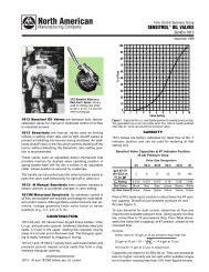
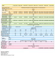
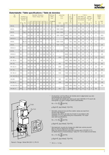
Datentabelle / Table specifications / Table de donnéesTyp Baumaße / Dimensions Bohrung pmax mbar V ' Kv* P 220 V GewichtType Anschluss Flansch / flange / bride drilling Kl. A p = beim Öffnen geöffnet WeightConnection trous Cl. A 1 mbar when opening when open PoidsRaccord Luft à l’ouverture ouvert **L H1 H2 H3 D1 D2 k d2 Anz./No. Air Al GGGDN Rp mm mm mm mm mm mm mm mm ALSi GGG m 3 /h VA W VA W kg kg<strong>VK</strong> 40.. – Rp 11⁄2 150 345 100 430 127 – – – – 1000 / 4000 – 27,5 31,3 90 50 9 9 8 –<strong>VK</strong> 40.. 40 – 200 345 100 430 127 150 110 18 4 1000 / 4000 – 27,5 31,3 90 50 9 9 9 –<strong>VK</strong> 50.. – Rp 2 180 350 117 435 155 – – – – 1000 / 4000 – 45,0 51,2 90 50 9 9 9 –<strong>VK</strong> 50.. 50 – 230 350 117 435 155 165 125 18 4 1000 / 4000 4000 45,0 51,2 90 50 9 9 11 20,5<strong>VK</strong> 50..H 50 – 230 414 117 – 155 165 125 18 4 – 8000 45,0 51,2 90 50 9 9 – 21<strong>VK</strong> 65.. – Rp 21⁄2 218 370 135 455 182 – – – – 1000 / 3100 – 70,0 79,6 90 50 9 9 11 –<strong>VK</strong> 65.. 65 – 290 370 135 455 182 185 145 18 4 1000 / 3100 3100 70,0 79,6 90 50 9 9 13 26<strong>VK</strong> 65..H 65 – 290 434 135 – 182 185 145 18 4 – 8000 70,0 79,6 90 50 9 9 – 27<strong>VK</strong> 80.. 80 – 310 378 137 463 210 200 160 18 8 1000 / 2400 2400 103,0 117,1 90 50 9 9 15 32<strong>VK</strong> 80..H 80 – 310 442 137 – 210 200 160 18 8 – 6000 103,0 117,1 90 50 9 9 – 33<strong>VK</strong> 100.. 100 – 350 400 163 485 248 229 180 18 8 1000 1000 148,0 168,3 90 50 9 9 19 41,5<strong>VK</strong> 100..H 100 – 350 464 163 – 248 220 180 18 8 – 4000 148,0 168,3 90 50 9 9 – 43<strong>VK</strong> 125.. 125 – 400 450 158 535 314 250 210 18 8 600 600 206,0 234,2 90 50 9 9 24 60<strong>VK</strong> 125..H 125 – 400 514 158 – 314 250 210 18 8 1000 2000 206,0 234,2 90 50 9 9 25 61<strong>VK</strong> 150.. 150 – 480 445 173 530 344 285 240 23 8 400 400 310,0 352,5 90 50 9 9 32 80<strong>VK</strong> 150..H 150 – 480 509 173 – 344 285 240 23 8 1000 1500 310,0 352,5 90 50 9 9 33 81<strong>VK</strong> 150/100..H 150 – 480 509 173 – 344 285 240 23 8 – 4000 148,0 168,3 90 50 9 9 – 81<strong>VK</strong> 200.. 200 – 600 475 218 560 420 340 295 23 12 230 230 490,0 557,2 90 50 9 9 52 141<strong>VK</strong> 200..H 200 – 600 539 218 – 420 340 295 23 12 1000 1000 490,0 557,2 90 50 9 9 53 142<strong>VK</strong> 200/100..H 200 – 600 539 218 – 420 340 295 23 12 – 4000 148,0 168,3 90 50 9 9 – 142<strong>VK</strong> 250..H 250 – 730 573 270 – 496 405 355 27 12 500 – 590,0 670,0 90 50 9 9 80 –* Druckverlust und Durchfluss der Ventile wird im allgemeinen aus denDurchflusskurven entnommen.Die Auswahl der Ventile kann aber auch nach VDI/VDE 2173 durch dieKenngröße „Kv-Wert“ erfolgen (siehe Datentabelle).120Pg 13,5Kv = V· x pρ [m 3/h]ρ [kg/m 3 ]; p [mbar]; V· [m 3 /h]* Normally, pressure loss and flow ratefor valves are read fromthe flow rate diagram.However, the valves can also be chosen in accordance withVDI/VDE 2173, by determining the characteristic “KV value”(see table specifications).H3H1nKv = V· x pρ [m 3/h]ρ [kg/m 3 ]; p [mbar]; V· [m 3 /h]D1 k d1* Normalement, la perte de charge et le débit des vannes peuventêtre lus dans le diagramme de débit.Mais, les vannes peuvent aussi être choisies selon VDI/VDE 2173,en déterminant la characteristique “valeur-Kv” (voir la table de données).H2LRp1/4Kv = V· x pρ [m 3/h]ρ [kg/m 3 ]; p [mbar]; V· [m 3 /h]Flansch / Flange / Bride DIN 2501 C, PN 16** <strong>VK</strong>..X, + 1,5 kg7