MOTOR OPERATED BUTTERFLY - System Control Engineering
MOTOR OPERATED BUTTERFLY - System Control Engineering
MOTOR OPERATED BUTTERFLY - System Control Engineering

You also want an ePaper? Increase the reach of your titles
YUMPU automatically turns print PDFs into web optimized ePapers that Google loves.
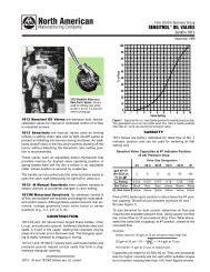
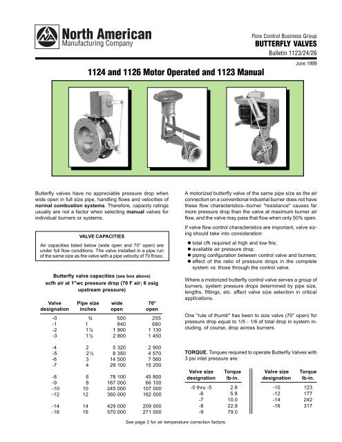
-6-F th -8-FSTANDARD VALVES(See also Bulletins 1122 [Manual], 1180 [Motorized], and 1154 [Resilient Seat Wafer])1124 Motorized 1126 Motorized 1126 (H) Hot Air Motorized 1123 ManualStandard butterfly valves have female pipe threads in ¾" through 6" pipe sizes; larger valves are flanged, as are1126-F in 3", 4", and 6" sizes. Motorized valves are furnished with bracket, motor arm, and linkage for standardcontrol motor or actuator. 1123 Manual valves have a locking handle and are available in 8" to 16" sizes. For ¾"through 6" sizes see Bulletin 11221126 and 1123 Valves have a swing-through disc.1124 Valves have a beveled disc for tighter shutoff; spring-loaded linkage is furnished when an electric operator isspecified (see Instructions 1230).All standard valves (except 1126- -H) can be used on gas. However, if UL approval is required for -0 through -8sizes, a "G" suffix is added to the designation.Standard 1122„, 1123, 1124, and 1126 Valves are suitable for air heated to 400 F. For 400 to 700 F, specify the 1122(H)„, 1124 (H), or 1126 (H) Valve with Grafoil seal.SPECIFICATIONS/CONSTRUCTIONValve Maximum inlet Maximumdesignation pressure, psi temperature, F Body Disc Shaft1122„, 1123,1124, 1126: 25 400ƒ cast iron steel ENP/brass‚-0 thru -4 threaded-5 thru -8 15 400ƒ " " " ‚-6-F thru -8-F 15 400ƒ cast iron " " ‚flanged-9 thru -16 5 400 " cast iron stainless steelCaution: Flanged Valves: Use flat flanges and full face gaskets when installing this equipment. Raised face flanges can damage the valve body.Additional Notes:‚ Electroless nickel plated brass.ƒ 700 F for 1122-(H), 1124-(H) and 1126-(H) which have Grafoil seals and 304 SST shafts.„ See Bulletin 1122.AIR TEMPERATURE CORRECTION FACTORS FOR ALL VALVESMultiply scfh in table by air temperature factor to get scfh air at that temperature.F factor F factor F factor60 1.0 300 0.83 800 0.64100 0.96 400 0.78 900 0.62150 0.92 500 0.74 1000 0.60200 0.89 600 0.70 1100 0.58250 0.86 700 0.67Bulletin 1123/24/26 Page 2
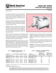
DimensionsinchesSTANDARD VALVES(dimensions apply also to "G" valves)Bolt holes on all flanged modelsare equally spaced and straddlevalve centerlines.ORDER MUST SPECIFY:1) Valve designation (for allvalves).2) Motor selected (for 1124 and2) 1126 Valves).1126-9 thru -161126-6-F thru 1126-8-F1124, 1126-0 thru -8Valvedimensions in inchesWt,designation A B C D F G H J K L M N P Q R S T U lb1124, 1126-0 3/4 2 1 /16 1 3 /16 2 3 /8 2 5 /16 1 3 /16 3 15 /16 1 1 /4 – 1/4 – – – – – – – 1 3 /8 51124, 1126-1 1 3 /4 2 1 /16 1 3 /16 2 3 /8 2 5 /16 1 3 /16 3 15 /16 1 1 /4 – 1/4 – – – – – – – 1 3 /8 51124, 1126-2 1 1 /4 2 5 /16 1 1 /4 2 1 /2 2 3 /8 1 5 /16 4 1 /8 1 3 /8 – 3/16 – – – – – – – 1 3 /8 5 1 /41124, 1126-3 1 1 /2 2 9 /16 1 5 /16 2 5 /8 2 1 /2 1 7 /16 4 3 /8 1 1 /2 – 1/16 – – – – – – – 1 3 /8 5 1 /21124, 1126-4 2 1 /4 3 3 /16 1 1 /2 3 1 /2 2 13 /16 1 3 /4 5 1 13 /16 1/4 – – – – – – – – 1 3 /8 6 1 /21124, 1126-5 2 1 /2 3 13 /16 1 3 /4 3 1 /2 3 1 /8 2 1 /8 5 11 /16 2 1 /8 9/16 – – – – – – – – 1 3 /8 8 1 /21124, 1126-6 3 1 /2 4 1 /2 1 15 /16 3 7 /8 3 3 /4 2 7 /16 6 5 /8 2 3 /8 1 3 /16 – – – – – – – – 1 3 /8 111124, 1126-7 4 1 /2 5 5 /8 2 1 /4 4 1 /2 4 5 /16 3 7 3 /4 2 15 /16 1 3 /4 – – – – – – – – 1 3 /8 15 1 /21124, 1126-8 6 1 /2 7 7 /8 2 9 /16 5 1 /8 5 7 /16 4 1 /8 10 4 1 /16 2 7 /8 – – – – – – – – 1 3 /8 271124, 1126-6-F 3 1 /2 7 1 /2 2 4 1 /2 5 1 /16 3 3 /4 9 1 /4 5 1 /16 1 – 6 3/4 4 1 /21124, 1126-7-F 4 1 /2 9 2 1 /4 4 1 /2 5 13 /16 4 1 /2 10 3 /4 4 5 /8 1 3 /4 – 7 1 /2 3/4 8 9 /161124, 1126-8-F 6 1 /2 11 2 1 /2 5/2 6 13 /16 5 1 /2 12 3 /4 5 5 /8 2 3 /4 – 9 1 /2 7/8 8 9 /167/8 1 1 /2 – 1 3 /8 207/8 1 1 /2 – 1 3 /8 247/8 1 1 /2 – 1 3 /8 341126-9 8 1 /2 13 1 /2 2 3 /4 5 1 /2 8 1 /4 6 3 /4 15 11 /16 7 5 /16 – – 11 3 /4 7/8 8 9 /16 1 3 /8 1 1 /8 1 1 /8 1 5 /8 551126-10 10/2 16 3 3 /4 7 1 /2 9 1 /2 8 18 3 /16 8 7 /16 1 1 /4 – 14 1 /4 1 12 3 /4 1 3 /8 1 1 /8 1 1 /8 1 5 /8 941126-12 12/2 19 4 8 1 /2 11 9 1 /2 21 3 /16 9 3 /4 2 3 /4 – 17 1 12 3 /4 1 3 /8 1 1 /8 1 1 /8 1 5 /8 1281126-14 14/2 21 4 8 1 /2 12 10 1 /2 23 3 /16 10 3 /4 3 3 /4 – 18 3 /4 1 1 /8 12 3 /4 1 3 /8 1 1 /8 1 1 /8 1 5 /8 1521126-16 16/2 23 1 /2 4 1 /4 8 1 /2 13 1 /4 11 3 /4 25 11 /16 12 1 /8 5 – 21 1 /4 1 1 /8 16 7 /8 1 3 /8 1 1 /8 1 1 /8 1 5 /8 1881123-9 8 1 /2 13 1 /2 2 3 /4 5 1 /2 8 1 /2 6 3 /4 15 1 /4 – – – 11 3 /4 7/8 8 9 /16 – – – – 521123-10 10/2 16 3 3 /4 7 1 /2 9 3 /4 8 17 3 /4 – – – 14 1 /4 1 12 3 /4 – – – – 911123-12 12/2 19 4 8 1 /2 11 1 /4 9 1 /2 20 3 /4 – – – 17 1 12 3 /4 – – – – 1251123-14 14/2 21 4 8 1 /2 12 1 /4 10 1 /2 22 3 /4 – – – 18 3 /4 1 1 /8 12 3 /4 – – – – 1491123-16 16/2 23 1 /2 4 1 /4 8 1 /2 13 1 /4 11 3 /4 25 1 /4 – – – 21 1 /4 1 1 /8 16 7 /8 – – – – 1851123ManualValves(-9 thru -16)¨ Minimum valve arm radius for attaching linkage is U, maximum is 5".Bulletin 1123/24/26 Page 3
Bulletin 1123/24/26Page 4DIMENSIONS SHOWN ARE SUBJECT TO CHANGE. PLEASE OBTAIN CERTIFIED PRINTS FROM NORTH AMERICAN MFG. CO.IF SPACE LIMITATIONS OR OTHER CONSIDERATIONS MAKE EXACT DIMENSION(S) CRITICAL.WARNING: Situations dangerous to personnel and property can develop from incorrect operation of combustion equipment.North American urges compliance with National Safety Standards and Insurance Underwriters recommendations, and care in operation.North American Mfg. Co., 4455 East 71st Street, Cleveland, OH 44105-5600 USA, Phone 216-271-6000, Facsimile 216-641-7852E-mail sales@namfg.com l www.namfg.comPrinted in USANA700-B1123/24/26