VK (D, GB, F) - System Control Engineering
VK (D, GB, F) - System Control Engineering
VK (D, GB, F) - System Control Engineering
- No tags were found...

You also want an ePaper? Increase the reach of your titles
YUMPU automatically turns print PDFs into web optimized ePapers that Google loves.
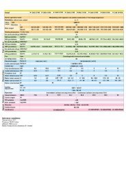
Datentabelle / Table specifications / Table de donnéesTyp Baumaße / Dimensions Bohrung pmax mbar V ' Kv* P 220 V GewichtType Anschluss Flansch / flange / bride drilling Kl. A p = beim Öffnen geöffnet WeightConnection trous Cl. A 1 mbar when opening when open PoidsRaccord Luft à l’ouverture ouvert **L H1 H2 H3 D1 D2 k d2 Anz./No. Air Al GGGDN Rp mm mm mm mm mm mm mm mm ALSi GGG m 3 /h VA W VA W kg kg<strong>VK</strong> 40.. – Rp 11⁄2 150 345 100 430 127 – – – – 1000 / 4000 – 27,5 31,3 90 50 9 9 8 –<strong>VK</strong> 40.. 40 – 200 345 100 430 127 150 110 18 4 1000 / 4000 – 27,5 31,3 90 50 9 9 9 –<strong>VK</strong> 50.. – Rp 2 180 350 117 435 155 – – – – 1000 / 4000 – 45,0 51,2 90 50 9 9 9 –<strong>VK</strong> 50.. 50 – 230 350 117 435 155 165 125 18 4 1000 / 4000 4000 45,0 51,2 90 50 9 9 11 20,5<strong>VK</strong> 50..H 50 – 230 414 117 – 155 165 125 18 4 – 8000 45,0 51,2 90 50 9 9 – 21<strong>VK</strong> 65.. – Rp 21⁄2 218 370 135 455 182 – – – – 1000 / 3100 – 70,0 79,6 90 50 9 9 11 –<strong>VK</strong> 65.. 65 – 290 370 135 455 182 185 145 18 4 1000 / 3100 3100 70,0 79,6 90 50 9 9 13 26<strong>VK</strong> 65..H 65 – 290 434 135 – 182 185 145 18 4 – 8000 70,0 79,6 90 50 9 9 – 27<strong>VK</strong> 80.. 80 – 310 378 137 463 210 200 160 18 8 1000 / 2400 2400 103,0 117,1 90 50 9 9 15 32<strong>VK</strong> 80..H 80 – 310 442 137 – 210 200 160 18 8 – 6000 103,0 117,1 90 50 9 9 – 33<strong>VK</strong> 100.. 100 – 350 400 163 485 248 229 180 18 8 1000 1000 148,0 168,3 90 50 9 9 19 41,5<strong>VK</strong> 100..H 100 – 350 464 163 – 248 220 180 18 8 – 4000 148,0 168,3 90 50 9 9 – 43<strong>VK</strong> 125.. 125 – 400 450 158 535 314 250 210 18 8 600 600 206,0 234,2 90 50 9 9 24 60<strong>VK</strong> 125..H 125 – 400 514 158 – 314 250 210 18 8 1000 2000 206,0 234,2 90 50 9 9 25 61<strong>VK</strong> 150.. 150 – 480 445 173 530 344 285 240 23 8 400 400 310,0 352,5 90 50 9 9 32 80<strong>VK</strong> 150..H 150 – 480 509 173 – 344 285 240 23 8 1000 1500 310,0 352,5 90 50 9 9 33 81<strong>VK</strong> 150/100..H 150 – 480 509 173 – 344 285 240 23 8 – 4000 148,0 168,3 90 50 9 9 – 81<strong>VK</strong> 200.. 200 – 600 475 218 560 420 340 295 23 12 230 230 490,0 557,2 90 50 9 9 52 141<strong>VK</strong> 200..H 200 – 600 539 218 – 420 340 295 23 12 1000 1000 490,0 557,2 90 50 9 9 53 142<strong>VK</strong> 200/100..H 200 – 600 539 218 – 420 340 295 23 12 – 4000 148,0 168,3 90 50 9 9 – 142<strong>VK</strong> 250..H 250 – 730 573 270 – 496 405 355 27 12 500 – 590,0 670,0 90 50 9 9 80 –* Druckverlust und Durchfluss der Ventile wird im allgemeinen aus denDurchflusskurven entnommen.Die Auswahl der Ventile kann aber auch nach VDI/VDE 2173 durch dieKenngröße „Kv-Wert“ erfolgen (siehe Datentabelle).120Pg 13,5Kv = V· x pρ [m 3/h]ρ [kg/m 3 ]; p [mbar]; V· [m 3 /h]* Normally, pressure loss and flow ratefor valves are read fromthe flow rate diagram.However, the valves can also be chosen in accordance withVDI/VDE 2173, by determining the characteristic “KV value”(see table specifications).H3H1nKv = V· x pρ [m 3/h]ρ [kg/m 3 ]; p [mbar]; V· [m 3 /h]D1 k d1* Normalement, la perte de charge et le débit des vannes peuventêtre lus dans le diagramme de débit.Mais, les vannes peuvent aussi être choisies selon VDI/VDE 2173,en déterminant la characteristique “valeur-Kv” (voir la table de données).H2LRp1/4Kv = V· x pρ [m 3/h]ρ [kg/m 3 ]; p [mbar]; V· [m 3 /h]Flansch / Flange / Bride DIN 2501 C, PN 16** <strong>VK</strong>..X, + 1,5 kg7
Volumenstrom-DiagrammVolume flow diagramDiagramme de débit volumiqueDruckverlust · Pressure drop · Perte de charge Dp [mbar] Volumenstrom nach EN 161Flow rate in acc. with EN 161Diagramme de débit selon EN 161 = Erdgas / Natural gas / Gaz naturel / dv = 0,62 = Flüssiggas / LPG / Gaz de pétrole liquéfié / dv = 1,56 = Stadtgas / Town gas / Gaz de ville / dv = 0,45 = Luft / Air / dv = 1,00Hinweis: Beim Einlesen von Betriebskubikmetern(ohne Umrechnung in m 3 [n]) indas Diagramm ist der abgelesene Druckverlustmit dem absoluten Druck in bar(1 + Überdruck in bar) zu multiplizieren.Note: When reading operating cubic metresin the diagram (without converting tom 3 [n]), the pressure loss as read, is to bemultiplied with the absolute pressure in bar(1 + positive pressure in bar).Remarque: En lisant la valeur en mêtre cubede service (sans conversion en m 3 [n])sur le diagramme, multiplier la perte depression lue avec la pression absolue enbar (1 + pression effective en bar).Beispiel: Im Motorventil <strong>VK</strong> 65 sindVolumenstrom = 200 m 3 /h ErdgasGasdruck = 1 bar200 m 3 /h ⇒ <strong>VK</strong> 65 ⇒ 5 mbarabgelesen im Diagrammp = 5 x (1 + 1) = 10 mbaram Motorventil <strong>VK</strong> 65Example: In the motorized valve <strong>VK</strong> 65flow rate = 200 m 3 /h natural gasgas pressure = 1 bar200 m 3 /h ⇒ <strong>VK</strong> 65 ⇒ 5 mbarread from the diagramp = 5 x (1 + 1) = 10 mbarat the motorized valve <strong>VK</strong> 65Exemple: Dans la vanne motorisée <strong>VK</strong> 65débit = 200 m 3 /hde gaz naturelpression de gaz = 1 bar200 m 3 /h ⇒ <strong>VK</strong> 65 ⇒ 5 mbarlu sur le diagrammep = 5 x (1 + 1) = 10 mbarà la vanne motorisée <strong>VK</strong> 658
Fig. 13ZubehörMeldeschalter (Fig. 13) bei <strong>VK</strong>..S (G)Diese Geräte sind mit einem Schalter für dieMeldung „geschlossen“ oder "nicht geschlossen"oder als Stufenmelder verwendbar.Anschlusswerte: 30 – 250 V, 50/60 Hz,max. 10 A (ohmsche Last) bei <strong>VK</strong>..S.Halterelais bei <strong>VK</strong>..RDas Halterelais für die "Wiederinbetriebnahmevon Hand" verhindert, dass nach einemSpannungsausfall das Gas automatischwieder freigegeben wird.Elektrischer Anschluss (Fig. 14)<strong>VK</strong>..<strong>VK</strong>..R Fig. 14AccessoriesPosition indicator (Fig. 13) on <strong>VK</strong>..S (G)These appliances can be used with a switchfor the indication "closed" or "not closed" oras step indicators.Connection ratings: 30 – 250 V, 50/60 Hz,max. 10 A (resistive load) on <strong>VK</strong>..S.Holding relay on <strong>VK</strong>..RThe holding relay for manual restart stopsgas from being automatically released againafter a power cut.Electrical connection (Fig. 14)<strong>VK</strong>..Z..S Fig. 15A=Com.B=NOC=NCAccessoiresIndicateur de position (Fig. 13) pour <strong>VK</strong>..S (G)Ces appareils peuvent être utilisés avec uncommutateur pour la signalisation „fermée“ou „non fermée“ ou en qualité d'indicateurd'étage.Raccordements: 30 à 250 V, 50/60 Hz,maxi 10 A (charge ohmique) pour <strong>VK</strong>..SRelais à maintien pour <strong>VK</strong>..RLe relais à maintien pour „remise en marchemanuelle“ évite qu'après une panne de courant,le gaz soit automatiquement libéré.Raccordement électrique (Fig. 14)9
G. Kromschröder AG Tel. ++49 (0)5 41/12 14-0 · Fax -3 70Postfach 2809 info@kromschroeder.comD-49018 Osnabrück www.kromschroeder.deTypenschlüssel <strong>VK</strong> 40 – 250Type code <strong>VK</strong> 40 – 250Code de type <strong>VK</strong> 40 à 250AuswahlSelectionChoix Standard / de série Option / option– nicht lieferbar/unavailable/non disponibleTechnische Änderungen, die dem Fortschritt dienen, vorbehaltenWe reserve the right to make technical changes designed toimprove our products without prior notice.Toutes les caractéristiques techniques sont sujettes à modificationssans avis préalable.10Typ/Type <strong>VK</strong> 40 F 10 Z* T5 X* A 9 3 D* S* R* V* F*Nennweite40, 50, 65, 80, 100, 125, 150, 150/100Nominal size 200, 200/100, 250Diamètre nominal<strong>VK</strong>.., <strong>VK</strong>..ZR F 02 04 06 10 24 31 40 Z** T5 W5 W6 Y Q6 M P T5/K A G*** 9 6 3 D S** S2 R** V F<strong>VK</strong> 40.. – – – – – – <strong>VK</strong> 50.. – – – – – <strong>VK</strong> 65.. – – – – – <strong>VK</strong> 80.. – – – – – – <strong>VK</strong> 100.. – – – – – – – <strong>VK</strong> 125.. – – – – – – – – <strong>VK</strong> 150.. – – – – – – – – <strong>VK</strong> 200.. – – – – – – – – – <strong>VK</strong>..HF 05 10 15 20 40 60 80 T5 W5 W6 Y Q6 M P T5/K A G 9 6 3 D S S2 R V F<strong>VK</strong> 50..H – – – – – – – <strong>VK</strong> 65..H – – – – – – – <strong>VK</strong> 80..H – – – – – – – <strong>VK</strong> 100..H – – – – – – – <strong>VK</strong> 125..H – – – – – – <strong>VK</strong> 150..H – – – – – – <strong>VK</strong> 150/100..H – – – – – – – – <strong>VK</strong> 200..H – – – – – – – – <strong>VK</strong> 20/100..H – – – – – – – – – <strong>VK</strong> 250..H – – – – – – – – – <strong>VK</strong>..XRp-GewindeFlanschRp-Thread = R Flange = FTauraudage Rp BrideMax. Eingangsdruck230 mbar = 02, 1000 mbar = 10, 3100 mbar = 31400 mbar = 04, 1500 mbar = 15, 4000 mbar = 40Maximale inlet pressure 500 mbar = 05, 2000 mbar = 20, 6000 mbar = 60Pression de entrèe max. 600 mbar = 06, 2400 mbar = 24, 8000 mbar = 80Zweistufig*2-step*A deux étages*NetzspannungMains voltageTension de secteur=Z*220/240 V~, 50 Hz = T5 120 V~, 60 Hz = Q6230 V~, 50 Hz = W5 110 V~, 50/60 Hz = M 230 V~, 60 Hz = W6 100 V~, 50/60 Hz = P220 V~, 50/60 Hz = Y 220 V~, 50 Hz/24 V= = T5/KExplosionsgeschützte Ausführung* Ausführung für höhere Eingangsdrücke*Actuator in explosion-proof version* = X* Version for higher inlet pressure* = H*Entraînement en modèle antidéflagrand* Version pour pressions de sotie supérieures*Ventilgehäuse-WerkstoffValve housing materialMatière du boîtier de la vanneMetall-Anschlusskasten mit Klemmen, IP 54 ... mit NormsteckdoseMetal connection box with terminals, IP 54... with standard socketBoîter de raccordement métalique avec bornes, IP 54 ... prise standardVerschluss-Schraube im Eingang und AusgangScrew at the inlet aund outlet = 3Vis à l’entrée et à la sotie=R*Mengeneinstellung*Flow adjutment* = D*Ajestement de débit*Meldeschalter*2 Meldeschalter*Postition indicator* = S* 2 Position indicator* = S2*Indication de position* 2 Indication de position*Halterelais*Holding relay*Relais à maintien*Viton-Ventiltellerdichtung*Viton-Valve disc seal* =V*Viton-Clapet*Sichtfenster*Viewing window* = F*Cadran*ALSI = AGGG 40 = G* Wenn „ohne“ entfällt dieser Buchstabe, d. h. der nächste rückt auf.* When “without”, this letter is droped, i. e. the next one moves up.* Si «sans», cette lettre est sans object, c’est-à-dire que la suivante est appelée.R F 02 04 06 10 24 31 40 W5 W6 M A G*** 9 3 D V F<strong>VK</strong> 40..X – – – – – – <strong>VK</strong> 50..X – – – – – <strong>VK</strong> 65..X – – – – – <strong>VK</strong> 80..X – – – – – – <strong>VK</strong> 100..X – – – – – – – <strong>VK</strong> 125..X – – – – – – – – <strong>VK</strong> 150..X – – – – – – – – <strong>VK</strong> 200..X – – – – – – – – – * In einigen EU-Ländern sind für Anschlüsse > DN 50 nur geflanschte Anschlüsse zulässig.Only flanged connections are permitted in certain EC countries for connections > DN 50.Dans certains pays de l’UE, seuls les raccordements à brides sont admis pour les raccordements > DN 50** Das <strong>VK</strong>..Z ist immer mit Meldeschalter, aber nicht mit Halterelais lieferbar.The <strong>VK</strong>..Z is always available with position indicator but not with holding relay.La vanne <strong>VK</strong>..Z peut être livrée avec un indicateur de position mais non pas avec un relais à maintien*** Beim <strong>VK</strong>..G gilt der höhere Eingangsdruck. Es ist nur mit Flanschanschluß lieferbar.The higher inlet pressure applies on the <strong>VK</strong>..G. Available only with flange connection.Pour la vanne <strong>VK</strong>..G, c'est la plus haute pression d'entrée qui est valable. Cette vanne ne peut être livrée qu'avecraccordement à bridesChez Kromschröder, la production respecte l’environnement.Demandez notre rapport environnemental.Kromschröder uses environment-friendly production methods.Please send away for our Environment Report.Kromschröder produziert umweltfreundlich.Fordern Sie unseren Umweltbericht an.03250022 1.01 F.T 5.000