EQUIPEMENTS DE LA HA 32 PX - AJ Maskin AS
EQUIPEMENTS DE LA HA 32 PX - AJ Maskin AS
EQUIPEMENTS DE LA HA 32 PX - AJ Maskin AS

Create successful ePaper yourself
Turn your PDF publications into a flip-book with our unique Google optimized e-Paper software.
<strong>HA</strong> 41 <strong>PX</strong>ELECTRIQUETraining Dpt - 2006 1
SOMMAIRE1-Introduction………………………………………………………………………………….……………………..<strong>32</strong>-capteurs de position/ limit switchs……………………………………………………………………………….53-emplacement capteurs/ limit switchs location………………………………………………………………….64-switchs tourelle / turret limit switch location…………………………………………………………………….75-Position essieux / axles position…………………………………………………………………………….... ..86-Emplacement capteurs flèche/ boom sensors location…………….…………………………………….10-117-Description des éléments machine / machine elements description……………………………………….127.1 les élements moteur/engine devices….…………………………………………………..………..127.2 Fusibles/ fuses………………………………………………………………..………………………127.3 Les relais / relays……………………………………………………………………………………..127.4 les électrovannes / electrovalves…………………………………….……………………………..137.5 les voyants/light indicators………………………………………………………….……………….137.6 les commutateurs/ toggle switchs……………………………………………….………………….147.7 les avertisseurs/beepers……………………………………………………….…………………….147.8 les accessoires/ accessories………………………………………………………………………..147.9 les diodes-résistances/ diodes –resistors………………………………………………………….157.10 Module………………………………………………………………………………………………..157.11 Manipulateurs/controllers…………………………………………………………………………..167.12 Signaux capteurs angle-longueur/ Angle and length transmiters signal sensors…………....168-Interconnexion nacelle-tourelle…………………………………………………….……………………..…….179-Procédure d’étalonnage / calibration procedure …………………………………………………………18-19Training Dpt - 2006 2
1-IntroductionPrincipales différences avec la <strong>HA</strong><strong>32</strong><strong>PX</strong>- Le calculateur Head gère désormais la commande de la pompe de translation (SM4 et YV30 A&B)- Les manipulateurs de commande sont différents car ils sont alimentés en 4-20mA, la consigne est doncdifférente :4mA 12 mA 20 mAPosition mini Point milieu (neutre) Position maxi0 .63 VDC 1.9 VDC 3.16 VDC125 points* 380 points* 645 points** points sur console Optimizer (permettent également de vérifier si les résistances d’adaptation R100 àR104 ne sont pas HS : dans le cas contraire, les valeurs en points sont décalés)- le soft Head a été modifié de telle sorte qu’il n’est plus possible de régler avec la console Optimizer lesparamètres de réglage côté tourelle (fixés à 85% des valeurs des paramètres de réglage côté panier)- le groupe de secours donne 100% de débit de façon à pouvoir procéder aux mouvements sansatteindre les 130 bars (évite chauffe moteur et gain de temps en descente d’urgence)- Une carte pesage gère désormais la surcharge en panier (système de capteurs d’angle pendulaire A1et A2 et de capteurs de pression G1 et G2 montés sur vérin pendulaire)Comme pour la <strong>HA</strong>260<strong>PX</strong>, cette carte pesage est alimentée en 12VDC (fil 242, connecteur J4.1), il y a unsurvolteur à l’intérieur pour alimenter les capteurs de pression en 16VDC et un transformateur 5VDC pouralimenter les capteurs potentiométriques A1 et A2.Les 2 relais internes détectent la surcharge (fil 213 et 214) :2 contacts fermés : fonctionnement normal2 contacts ouverts : surcharge1 fermé, 1 ouvert (on est en butée de vérin) : donc soit coupure montée ( contact fermé ) ou soit coupuredescente ( si contact ouvert) suivant le cas .La commande Apprentissage (Jib learning) se fait par le fil 607.- sur la flèche principale, il est installé 3 connecteurs haute résistance faisant l’interconnexion des câblesprincipaux venant du panier et allant au pupitre bas ( 2 pour les câbles de 30 mm2 et 1 pour l’extension220 VAC ) , le démontage de la flèche s’en trouve facilitée.- Un système de capteurs d’angle et de longueur gère désormais la limitation de portée bras et flèche(SL3, SL4, SL7, SL8, SQ43, SQ44 et SQ45)- La limitation de la compensation manuelle panier (+ 10° / - 10°) est faite par les signaux venant de lacarte pesage U2 (fils 390 et 391)- les entrées pendulaire et compensation panier ont été relayées (un seul interrupteur pour commandercôté panier et côté tourelle, voir diode D<strong>32</strong> et D34 pour éviter les retours de tension)- les relais d’aiguillage KA50 et KA51 permettent de gérer les synchronisations entre bras et flèche- les capteurs SQ43 pour la flèche et SQ44 et 45 pour le bras sont des capteurs ILS (ils réagissent enfonction des aimants positionnés sur le fût du télescope)Le klaxon est relayé (commandé par SB5 et KM8)Training Dpt - 2006 3
Main differences with the <strong>HA</strong><strong>32</strong><strong>PX</strong>- the Head module takes care of the drive pump command (SM4 and YV30 A&B),- the controllers are different as they are supplied in 4-20mA current , therefore the setpoint is different :4mA 12 mA 20 mAMini position Middle position Maxi position0 .63 VDC 1.9 VDC 3.16 VDC125 points* 380 points* 645 points** points read on Optimizer calibrator (by this , we can also check that the impedance from R100 to R104are not OK : in the contrary case , the values in points are shifted fwd)- the Head software has been modified , its not anymore possible to adjust with the Optimizer calibrator ,the setting parameters from turret movements ( they are fixed at 85% of setting parameters from cagemovements)- the emergency pump gives now 100% of flow for the movements before reaching the 130 bars ( avoidmotor overheating and save time in case of emergency descent)- An overload board takes care about the cage overload device (system controlled by angle transmittersA1 and A2 and pressure sensors on jib cylinder G1 and G2)As per <strong>HA</strong>260<strong>PX</strong>, this overload board is supplied in 12VDC( wire 242, terminal J4.1) , inside there is abooster in order to supply the pressure sensors in 16VDC and a transformer 5VDC for the transmitters A1and A2.The internal relays detect the overload (wires 213 and 214) :- 2 contacts closed : normal condition- 2 contacts opened : overload- 1 closed , 1 open ( ex bottom of cylinder) : so either lift cut ( contact closed) or descent is cut (contact open) depends which one .The overload calibration ( jib learning) is done on wire 607.On main boom , 3 high resistant connector which make the interconnection between upper and lowercontrol box ( 2 cables of 30x 1 mm2 and one for 220VAC option), it’s easier for boom dismantlingA system of angle and length transmitters manage the outreach limitation for both booms (SL3, SL4, SL7,SL8, SQ43, SQ44 and SQ45)The manual cage compensation is limited at +/- 10% and command by the signals coming from theoverload board U2.The input jib and cage compensation are relayed ( one toggle switch for both commands see diode D<strong>32</strong>and D34)The dispatch relay KA50 and KA51 manage the synchronisations between the booms.The proximity sensors ( SQ43 for main boom ) and SQ44 and SQ45 for primary booms detects the lengthof the booms thanks to the magnets fixed along the boom element.Buzzer is relayed ( SB5 and KM8)Training Dpt - 2006 4
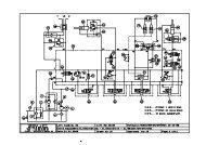
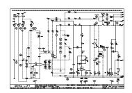
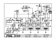
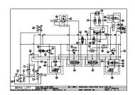
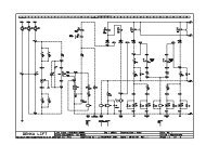
PARTIE ELECTRIQUE/ELECTRICAL DIAGRAM (schéma code 159P240710 )2-Les capteurs de position - limit switchs and sensorsDésignationElémentB1Filtre à air colmaté / air filter cloggedB2Surchauffe thermique / engine overheatingB3Manque pression huile /lack of engine oil pressureB4Surchauffe huile hydraulique / overheating hyd oilB7Option Refroidisseur / oil cooler sensorB8translation grande vitesse / Not high speedSQ1 Dévers (coupe tous mouvements / Slope ( cut all movements > above 3MSQ2 Pendulaire bas ( coupure GV) / lower jib ( cut High speed)SQ3 Flèche en zone de repliement ( coupure descente bras + sortie télesco+ GV)/ boom in folded zone ( cut HS,ddescent and telescopic exit)SQ9 Télescope flèche rentré ( coupure descente flèche) / boom telescop in ( cut boom descent)SQ10 Télescope bras rentré ( coupure descente bras)/ primary boom telescop in ( cut arm primary boom descent)SQ11 Flèche sur tourelle ( coupure sortie extension)/ boom on turret( cut axles extension exit)SQ12 Rupture chaîne 1 ( coupure tous mouvements )/ chain broken 1( cut all movements)SQ13 Rupture chaîne 2 ( coupure tous mouvements)/ chain broken 2 ( cut all movements)SQ30 Essieu AVG étendu ( coupure mouvements sauf orientation et relevage flèche)/ left front axle extended ( cutmovements except turret rotation and boom lifting)SQ31 Essieu AV D étendus ( idem ci-dessus)/ right front axle extended ( same as above)SQ<strong>32</strong> Essieu AR D étendus ( idem ci-dessus) / right rear axle extended (same as above)SQ33 Essieu AR G étendu ( idem ci-dessus) / left rear axle extended ( same as above)SQ34 Calage avant rentré ( idem ci-dessus) / front outrigger retracted ( same as above)SQ35 Calage arrière rentrés ( idem ci-dessus) / rear outrigger retracted ( same as above)SQ36 Essieux AV étendus ( idem ci-dessous) / front extended axles ( same as above)SQ37 Essieux AR étendus ( idem ci-dessous) / rear extended axles ( same as above)SQ38 Essieux AV rentrés ( idem ci-dessous) / front axles retracted ( same as above)SQ39 Essieux AR rentrés ( idem ci-dessous) / rear axles retracted ( same as above)SQ40 Tourelle axée avec le châssis ( coupe sortie extension essieux)/ turret centered on chassis ( cut the axleextension exit)SQ41 Réserve carburant / fuel levelSQ42 Tourelle axée avec le châssis (coupe sortie extension essieux / turret centered on chassis ( cut the axleextension exit)SQ43 Détection télescopage flèche ( capteur ILS) ( surveille la limitation de portée)/ main telescopic boomdetection ( proximity sensor) , ( check the outreach limitation)SQ44 Détection télescopage bras fût 1 ( capteur ILS) ( idem ci-dessus)/ primary telescopic boom section Idetection ( proximity sensor), ( same as above)SQ45 Détection télescopage bras fût 2 ( capteur ILS), ( idem ci-dessus) ( / primary telescopic boom section IIdetection ( proximity sensor), ( same as above)SL1 Capteur angle flèche I / boom angle I transducerSL2 Capteur angle fleche II / boom angle II transducerSL3 Capteur longueur fleche I / boom length I transducerSL4 Capteur longueur fleche II / boom length II transducerSL5 Capteur angle bras I / primary boom angle I transducerSL6 Capteur angle bras II / primary boom angle II transducerSL7 Capteur longueur bras I / primary boom length I transducerSL8 Capteur longueur bras II / primary boom length II transducerA1Capteur angle relatif pesage / relative angle transducer for overloadA2Capteur angle absolu pesage / absolute angle transducer for overloadG1Capteur pression PC / pressure sensor on jib cylinder ( small chamber)G2Capteur pression GC / pressure sensor on jib cylinder ( big chamber)Training Dpt - 2006 5
3-Emplacement capteurs/ sensors locationSQ9SQ13SQ9 : capteur télescope flèche rentré / main boom sensor retractedSQ13: capteur chaîne cassé / sensor chain breakdownSQ12 capteur chaine cassé / sensor chain breakdownSQ10SQ11SQ10 : Télescope bras rentré / primaryboom telescopic boom retractedSQ11 : capteur flèche sur tourelle/boom sensor on turretTraining Dpt - 2006 6
4-Capteur position de la tourelle/ sensor location on turretSQ42SQ40Angle de la tourelle avec le châssisBCouronne / gearCBAABCBTourelle axée avec le chassis/ turret alignedSQ42 : il y a deux aimants pour les deux positions (en marche avant et en marche arrière)SQ42 : there is 2 magnets for the both positions ( front and rear position)SQ40 : capteur électrique (sens opposé avec le capteur hydraulique)SQ40 : electric sensor ( opposite side with the hydraulic detector)Training Dpt - 2006 7
Zones A Zones B Zones CSQ40 1 1 0SQ42 1 0 05-Détection de la position des essieux/ axles position detection switchsSQ30SQ33C B AA B CAvant(front)ArrièreC B AA B C(rear)A : essieu rentré / axle inC : essieu sorti / axle outB : essieu en position intermédiaire / axle in intermediate positionEssieu Avant/ front axle Zones A Zones B Zones CSQ30 – 31 0 0 1SQ36 (reed) 0 0 1SQ38 (reed) 1 0 0Essieux Arrière/rear axle Zones A Zones B Zones CSQ<strong>32</strong> – 33 0 0 1SQ37 (reed) 0 0 1SQ39 (reed) 1 0 0SQ 36 à SQ 39 fixé sur vérins essieuxSQ36 up to SQ39 fixed on axles cylindersRemarquePour accéder aux capteurs magnétiques (Reed) SQ36,37,38 et SQ39 qui sont sur les vérins d’extensioncaisson des essieux, via un connecteur, il est nécessaire de sortir le vérin en démontant la roue(réducteur, moteur de translation, axe,…)Note :To have access to magnetic sensor (Reed) SQ36,37,38 and SQ39 that are fixed on cylinder of axleextension, it’s necessary to take out the cylinder by dismantling the wheel (reducer, drive motor, axle…)Training Dpt - 2006 8
SQ42SQ40SQ30-31SQ36-38SQ34-SQ35SQ<strong>32</strong>-33SQ37-39Training Dpt - 2006 9
6- Emplacement capteurs flèche/ boom sensors locationFlèche AR et pièce compensation intermédiaire / rear boom and intermediate compensation plateSL1SL2 ( AR intérieurflèche) / on rear partinside boomSQ45SQ44SQ12( chain)SL3-SL4SQ3 / Boom positionDétail vue AR flèche- Rear viewSQ3 est surveillé en permanence , il doit rester ouvert entre – 5° et + 65° sinon arrêts des mouvementsen cours et l’opérateur ne peut qu’exécuter des mouvements de descente.- Réglage SQ3Voir dans console Optimizer : Diagnostic/Boom/boom angle siSQ3 se ferme entre les valeurs 3950 et 3050 lues sur Optimizer (angle – 5° réels)SQ3 s’ouvre entre les valeurs 10650 et 10350 lues sur Optimizer (angle 65° réels)(pour information réglage came 1.4mm pour 1°)- SQ44 et SQ45 sont des capteurs ILS ( idem <strong>HA</strong>260<strong>PX</strong>) détectent les zones de télescope en réagissantau passage des aimants .SQ3 is checked permanently , it must be open between -5° and + 65° otherwise movements are cut andonly descent movements could be performed by the driver.- Setting SQ3 limit switch :See Optimizer calibrator : menu Diagnostic/Boom/ boom angleSQ3 is closed between 3950 and 3050 values read on display ( real angle -5° see hydraulic manual pag 3SQ3 is opened between 10650 and 10350 values shown on display ( real angle 65°)(Note that the way to adjust the wedge is 1.4mm for 1° )- SQ44 and SQ45 are proximity sensors ( same as for <strong>HA</strong>260<strong>PX</strong>) , they detect the telescopic area whenthe magnet are passing by in front of them ( gap around 10mm)Training Dpt - 2006 10
BR<strong>AS</strong>/PRIMARY BOOMARG/rear leftARG intérieur/rear left insideSQ11SL6SQ10 SL7-SL8 SL5Flèche partie AV + pendulaire / Front part of the boom + jibSQ43SQ9A2A1SQ2SQ13G2G1SQ43 est un capteur ILS ( idem <strong>HA</strong>260<strong>PX</strong>) : détecte les zones de télescope en réagissant au passagedes aimants /SQ43 is a proximity sensor and detects the magnets when passing by in front of themSQ11 : Flèche sur tourelle ( coupure sortie extension)/ boom on turret( cut axles extension exit)SQ9 : Tél escope flèche rentré ( coupure descente flèche) / boom telescop in ( cut boom descent)SQ2 : Pendulaire bas ( coupure GV) / jib detection for High Speed cutTraining Dpt - 2006 11
7-Description des éléments machine/ machine element description7-1 Les éléments moteur / engine devicesRep Description CaractéristiquesG2 Alternateur/ Alternator 12V / 65A.M3 Démarreur / Starter 3 kW.R1 Bougies de préchauffage / preheating candles 12V / 4 x 21A (en option).YA2 Accélérateur / accelerator 12V, courant d’appel 46A,courant de maintien 1,1A.YA1 Pompe à carburant/ gas-oil pump 12V / 4,5A.YA3 Pompe à injection / injection pump ESOS : 12V / 2AKSB-ALFB : 12V / 6A7-2 fusibles / fusesRep Description CaractéristiquesFU1 Fusible alimentation bobine moteur thermique/ thermal engine coil supply 10AFU2 Fusible commandes châssis./ chassis commands 3AFU3 Fusible bougies de préchauffage (moteur Perkins)/ preheating candles 80AFU4 Fusible démarreur./ starter 30AFU5 Fusible commandes tourelle/ turret commands 3AFU6 Fusible commandes panier/ cage commands 3AFU7 Fusible alimentation électrovannes/ valves supply 20AFU8 Fusible capteurs / sensors and limit switchs 5AFU9 Fusible pompe à injection Perkins/ injection engine pump 20AFU10 Fusible valve YV1 LS / load sensing valve ( dump valve) 3AFU11 Fusible refroidisseur./ cooler 25AFU13 Fusible pompe de secours/ emergency pump 250AFU14 Fusible accélérateur (moteur Perkins)/ engine accelerator 15AFU15 Fusible accessoires. 25A7.3 Les relais- relaysRep Description CaractéristiquesKMG Contacteur général / main relay 12V / 70AKM4 Pompe de secours / emergency pump 12V / 100AKA43 Coupure pompe de secours / emergency pump cut out 12V / 25AKA37 Alimentation accessoires / accessories supply 12V / 25AKA46 Alimentation pompe de translation et électrovanne défreinage/ brakes release 12V / 25AKM5 Préchauffage (Perkins)/ preheating 12V / 70AKM6 Accélérateur (Perkins)/ accelerator 12V / 70AKM7 Coupure moteur thermique/ thermal engine cut out 12V / 25AKM8 Klaxon / buzzer 12V / 25AKP1 Alimentation moteur / engine supply 12V / 25AKT2 Accélérateur (Deutz) Non Utilisé / Not used 12V / 25AKA2 Démarreur / starter 12V / 25AKA50 Aiguillage consigne télescopage flèche/levage bras / dispatch tel.boom/arm lift 12V / 25AKA51 Aiguillage consigne relevage flèche/télescopage bras/ dispatch boom/tel.arm 12V / 25ATraining Dpt - 2006 12
7.4 Les électrovannes – proportionnal valvesDésignation Description CaractéristiquesYV1 Valve LS / load sensing valve ( dump valve) 12V / 25WYV2PVG pendulaire, compensation , rotation panier , extension d’essieu, 12V / 5Wcalage, direction / jib, cage, axles outriggers, steering valveYV3 PVG levage bras / primary boom lift 12V / 5WYV4 PVG relevage flèche / main boom lift 12V / 5WYV5 PVG orientation / turret rotation 12V / 5WYV6 PVG télescope bras / primary telescopic boom 12V / 5WYV7 PVG télescope flèche / main telescopic boom 12V / 5WYV8Sélection extension d’essieu, calage, direction/ selection axle, 12V / 38Wextension, outriggers,steeringYV9 Blocage différentiel / differential lock 12V / 17WYV10 Grande vitesse de translation / High speed drive 12V / 17WYV12 Défreinage essieux / brake release for axles 12V / 17WYV15A – YV15B Compensation ( D et M) / cage levelling ( down and up) 12V / 17WYV18A – YV18B Pendulaire ( D et M) / jib ( down and up) 12V / 17WYV19A – YV19B Rotation panier ( D et G) / cage rotation ( Right and left) 12V / 17WYV21A – YV21B Direction avant ( D et G) / front steering ( right and left) 12V / 21WYV22A – YV22B Direction arrière ( D et G) / rear steering ( right an left) 12V / 21WYV24 Génératrice ( option) 12V / 30WYV30A – YV30B Pompe de translation ( MAV et MAR) / drive pump ( FWD and REV) 12V / 1,2AYV31Sélection extension d’essieu, calage, direction/ selection axle, 12V / 20Wextension, outriggers,steeringYV33 Déblocage essieu oscillant / oscillating axle release device 12V / 26WYV34 Déblocage tourelle orientation / turret rotation release device 12V / 20WYV35Télescopage bras fût 1/ primary boom telescopic section IYV36Télescopage bras fût 2/ primary boom telescopic section IIYV38Sécurité descente levage bras / safety device for arm lift ( descent)YV40 Recalage compensation bras / arm levelling manual compensation cancelled7.5 Les voyants/ light indicatorsRep Description CaractéristiquesHL1 Voyant batterie / battery indicator 12V / 2W – rouge / redHL2 Voyant surcharge tourelle / overload light on turret 12V / 2W – rouge / redHL3 Voyant surchauffe thermique / engine overheating indicator 12V / 2W – rouge / redHL4 Voyant pression huile / oil pressure indicatort 12V / 2W – rouge / redHL5 Option gyrophare/ beacon light 12V / 80WHL6 Option projecteur/ working lights 12V / 70WHL7 Voyant mise sous tension panier/ cage supply indicator 12V / 2W – vert / greenHL8 Voyant réserve carburant / tank indicator 12V / 2W - orangeHL9 Voyant défaut machine / failure indicator 12V / 2W – rouge / redHL10 Voyant surcharge panier / overload indicator on cage 12V / 2W – rouge / redHL11 Voyant préchauffage (Perkins) / engine preheating indicator 12V / 2W - orangeHL12 Voyant dévers / slope sensor indicator 12V / 2W – rouge / redHL14 Voyant limitation portée atteinte (tourelle )/ outreach limitation 12V / 2W - orangeindicator ( turret)HL15 Voyant limitation portée atteinte (panier) outreach limitationindicator ( cage)12V / 2W - orangeTraining Dpt - 2006 13
7.6 Les commutateurs / toggle switchesRep Description DescriptionSA0 Mise sous tension - tourelle / Power on - turretSA1 Sélection du poste de conduite ( tourelle/nacelle) Command selection (turret T/ cage N)SA2 Accélérateur (tourelle) acceleratorSA3 Blocage différentiel Differential lockSA4 Rotation panier (panier) Cage rotation ( from cage)SA5 Compensation (panier) Cage levellingSA6 Pendulaire - tourelle Jib (from turret)SA7 Pendulaire (panier) Jin ( from cage)SA8 Télescopage flèche (tourelle) Main telescopic boom ( from turret)SA9 Sélection bras/ (panier) Primary boom selection ( from cage)SA10 Télescopage bras (tourelle)Primary telescopic boom ( from turret)SA11 Grande vitesse de translationHigh speed driveSA12 Direction arrière G et DRear steering ( left and right)SA13 Relevage flèche-tourelleMain boom lift ( from turret)SA14 Levage bras - tourellePrimary boom lift ( from turret)SA15 Orientation tourelle – tourelle /Turret rotation ( from turret)SA16 Gyrophare – tourelle /Beacon ( from turret)SA17 Grande vitesse panier /High speed for cage movementSA18 Génératrice (option)Generator ( option)SA19 Pompe de secours – tourelleEmergency pump ( from turret)SA20 Pompe de secours - panierEmergency pump ( from cage)SA21 Compensation - tourelleCage levelling ( from turret)SB0 Arrêt d’urgence châssis ( essieux) E-stop ( from chassis for axles)SB1 Arrêt d’urgence tourelle E-stop from turretSB2 Arrêt d’urgence panier E-stop from cageSB3 Démarrage - tourelle Start from turretSB4 Démarrage - panier Start from cageSB5 Klaxon / buzzerSB6 Homme mort Foot dead man switchSB7 Préchauffage Perkins - tourelle / Engine preheatingSB8 Validation de compensation - tourelle / Cage levelling validation from turret7.7 Les avertisseurs / beepersDésignation Description Caractéristiques<strong>HA</strong>1 Klaxon / buzzer 12V / 72W<strong>HA</strong>2 Buzzer surcharge (panier)/ overload from cage 12V<strong>HA</strong>4 Bruiteur surcharge ( tourelle)/ overload from turret 12V / 300mA7.8 Les accessoires / accessoriesDésignation Description CaractéristiquesGB1 Batterie au plomb 12V/lead battery 12V 870A 135AhHL5 Gyrophare/ beacon 12V / 80WHL6 Projecteur/ working light 12V / 70WP1 Horamètre/ hourmeter 12VTraining Dpt - 2006 14
7.9 diodes – résistances / diodes - resistorsDésignation Description CaractéristiquesD1 Diode de roue libre (démarreur) / diode for starter 1N4007D2 Diode de roue libre (platine) / diode on PC board 1N4007D3 Diode de roue libre (platine) / diode on PC board 1N4007D4 Diode de roue libre (platine) / diode on PC board 1N4007D5 Diode de roue libre (platine horamètre) / diode on hourmeter 1N4007D6 Diode de roue libre (platine KM4) / diode on KM4 1N4007D7 Diode de roue libre (platine) / diode on PC board 1N4007D8 Diode de roue libre (relais KMG) / diode for KMG relay 1N4007D27 Diode de roue libre( bobine accel)/ diode for accelerator coil 1N4007D29 Diode de roue libre ( pompe à injection)/diode for injection pump 1N4007D<strong>32</strong> Diode anti-retour / anti return diode 1N4007D33 Diode anti-retour / anti return diode 1N4007D34 Diode anti-retour / anti return diode 1N4007D35 Diode anti-retour / anti return diode 1N4007D36 Diode anti-retour / anti return diode 1N4007D37 Diode anti-retour / anti return diode 1N4007D38 Diode anti-retour / anti return diode 1N4007Rad Résistance pull-down (platine) /pulll dow resistor 200 Ohms / 1WR100Résistance adaptation impédance consigne manipulateur 470 ohms/ ¼ WImpedance adapter for controller setpointR101Résistance adaptation impédance consigne manipulateur 470 ohms/ ¼ WImpedance adapter for controller setpointR102Résistance adaptation impédance consigne manipulateur 470 ohms/ ¼ WImpedance adapter for controller setpointR103Résistance adaptation impédance consigne manipulateur 470 ohms/ ¼ WImpedance adapter for controller setpointR104 Résistance protection bruiteur/ protection on beeper 220 ohms 2 WR105Résistance adaptation impédance signal sortie capteur301 ohms ¼ WImpedance adapter for output signal on transmitterR106Résistance adaptation impédance signal sortie capteur301 ohms ¼ WImpedance adapter for output signal on transmitterR107Résistance adaptation impédance signal sortie capteur301 ohms ¼ WImpedance adapter for output signal on transmitterR108Résistance adaptation impédance signal sortie capteur301 ohms ¼ WImpedance adapter for output signal on transmitterR28 Résistance protection bruiteur/ protection on beeper 1 KOhms / 0,25W7.10 moduleDésignation Elément CaractéristiquesU1 Calculateur système Head noeud A / Head module node A Consommation : 3W7.11 manipulateurs - controllersDésignation Elément CaractéristiquesSM31 Manipulateur orientation etlevage / slewing andboom lift joystickConstructeur : ITTConsommation : 2W2 axesSignaux de sortie analogiques : 4-20mAUn signal d’hors neutre type digitalTraining Dpt - 2006 15
SM2 Manipulateur télescopage /telescopic boom joystickSM4 Manipulateur translation /drive joystickConstructeur : ITTConsommation : 2W1 axeUn signal d’hors neutre type digitalSignaux de sortie en 4-20mAConstructeur : ITTConsommation : 2W1 axeSignal de sortie analogique : 4-20mAUn signal d’hors neutre type digitalDeux signaux de direction type digitalLes signauxTêtes Danfoss type PVEA / PVEA Solenoid valve DanfossSignal en tension 25% à 75% de la tension batterie Vbat (Vbat around+12V).Pour 50% de la tension de la batterie, la valve est au neutre.Entre 50% et 75%, on va dans un sens, entre 25% et 50%, on va dans l’autre sens.Bobine de pompe hydraulique / Solenoid of hydraulic pumpSignal en courant 0 à 1115mAEntre 0 et 400mA, le plateau n’est pas commandé.Entre 400mA et 1115mA, le plateau est déplacé proportionnellement.7.12 Signaux des capteurs angle et longueur / angle and length transmitters signal sensorsCapteurAngle / coursemachine( lu surconsole)/ read oncalibratorAngle / coursecapteur (plage-60à+60°)Tension capteur (V)SL5 butée min 0° -40° 1,402 ( 1.19-1.64)Angle bras/armCourse bras/arm coarseAngleflèche/boomCourse Flèche/boom coarseSL5 butée max 78° +38° 4,093 ( 3.85-4.31)SL6 butée min 0° +40° 4,151( 3.91-4.36)SL6 butée max 78° -38° 1,46( 1.24-1.64)SL7 butéerentrée/INSL7 butéesorti/OUTSL8 butéerentrée/INSL8 butéesorti /OUT0 1857655 78406,56% de Vbatt(3.01%-10.11%)71,27% de Vbatt (67.72%-74.82%)0 185 6,56% de Vbatt7655 7840 71,27% de VbattSL1 butée min 0° ( -40°) +55° 4,528 (4.34-4.63)SL1 butée max 110° (70°) -55° 1,025( 0.93-1.21)SL2 butée min 0° (-40°) -55° 1,025 (0.93-1.21)SL2 butée max 110° (70°) +55° 4,528 (4.34-4.63)SL3 butéerentrée/INSL3 butéesorti/OUTSL4 butéerentrée/INSL4 butéesorti/OUT0 14011960 61206,18% de Vbatt(2.63%-9.73ù)56,73% de Vbatt (53.18%-60.28%)0 140 6,18% de Vbatt11960 6120 56,73% de VbattTraining Dpt - 2006 16
8-Interconnexion Nacelle-Tourelle câbles bras /flèche N1 et N2/ wires connection in plugs N1 andN2 ( primary and main booms )N3 (option 220VAC)From R100 to R 108 , those resistors are mounted inside the turret box(except R104 which is mounted directly on buzzer terminals)Diodes D33-D35-D36 are mounted inside the cage boxTraining Dpt - 2006 17
9-Procédure d’étalonnage pour la limitation de portéePoint 1.Pendant la procédure la machine n'est jamais mise hors tension, le moteur est démarré, la machine n'estpas en dévers. Attention, l'utilisation de la console est nécessaire; pour la calibration l'utilisateur devraêtre en niveau 2 ( Menus Optimizer/ parameters/option/enter et access code 2031 level 2). Le respect dupositionnement des éléments machines (butées mécaniques) est capital.( vérifier dans le menu Failures ,qu'il n'y ait aucune alarme et que la compensation manuelle du bras ait été faite)Point 2.Le calculateur est en mode "Calibration" : les voyants du pupitre tourelle clignotent, le bruiteur tourelleémet des bips. Si ce n'est pas le cas, annuler la calibration précédente (menuParameters/Calibration/Radius Limit/ Cancel) puis mettre hors et sous tension la machine et redémarrerle moteur.Point 3.Calibrer en position 1: s'assurer que la machine est totalement repliée: rentrer le télescope flèche enbutée, faire de la descente bras de façon à ce que bras et télescope bras soient en butée, faire de ladescente flèche. le positionnement des autres éléments mécaniques (pendulaire ,tourelle)n'a pasd'importance.Point 4.Valider la position n°1 avec la console (menu Parameters /Calibration/Radius Limit: Pos.1).mettre Activeavec la touche verte pour valider puis * (le message OK apparait à l’écran)L’état des capteurs SL1 à SL8 et le message OK apparaisse à l’écran de la manière suivante :SL12345678--000000Point 5.Calibrer la position n°2 amener le bras en butée haute, puis sortir le télescope bras en butée sortie, leverla flèche en butée, sortir le télescope flèche en butée. le positionnement des autres éléments mécaniques(pendulaire, tourelle) n'a pas d'importance.Le message OK apparait à l’écran , L’état des capteurs SL1 à SL8 apparait en bas de l’écranPoint 6 .Valider la position n°2 avec la console (menu Parameters/Calibration/Radius Limit: Pos.2).mettre Activeavec la touche verte pour valider puis *, le message suivant apparait à l’écran :SL1234567800000000Point 7.Calibrer la position 3 ; rentrer la flèche en butée, descendre la flèche en butée ;Le positionnement desautres éléments mécanique ( pendulaire ,tourelle) n'a pas d'importance.( A cette étape , on ne vérifie que l’angle mini de la flèche avec SL1 et SL2)Point 8Valider la position n°3 avec la console (menu paramètre /calibration/Radius Limit: pos.3 ) mettre Activeavec la touche verte pour valider puis *, le message suivant apparait :SL1234567800----------Point 9La procédure de calibration est terminée(monter la flèche jusqu'à l'horizontale pour redescendre le bras)Point 10.Vérifier que la machine est calibrée: les voyant tourelle ne clignotent plus et le bruiteur tourelle n'émetplus de bip, sinon aller dans le menu Failures afin de trouver la panne.Point 11.Afin de vérifier que le système fonctionne convenablement faire de la descente flèche en limite d'abaque,moteur accéléré.Vérifier que le télescope est automatique rentré afin de respecter l'abaque de la machine. Vérifierpendant la descente que le paramètre Stroke Error (Diagnostic/Radius Lim.) ne dépasse pas 300mm;Vérifier également le fonctionnement de l'asservissement du bras.Note :O : capteur OKN :capteur hors tolérance ou HS- : capteur non vérifié à cette étape*Pour l’étalonnage pesage ,voir TN AT003 procédure type <strong>HA</strong>260<strong>PX</strong>Training Dpt - 2006 18
Calibration process for radius limit :Point 1During all the process, the machine should be always ON, engine started and not in slope., All themachine elements must be retracted ( in mechanical stop),The calibrator Optimizer is necessary and must set in level 2 (Parameters / option / access code 2031and validate by *)Check in Failure s menu that there is no alarm before starting the calibration process and make a primaryboom manual levelling (black button located near the proportional valves element PVG)Point 2The Head module is in "Calibration" mode: the lights on lower control panel should flash and the beepgives sound .If not, cancel the previous calibration (menu Parameters/Calibration/Radius Limit/ Cancel)then switch off and switch on again the machine and restart the engine.Point 3Calibration in position 1: be sure the machine is completely in folded position: fully retract the boomtelescopic cylinder, get down the telescopic primary boom and the primary boom too, the main boomshould also be folded ( the position of others movements such as turret or jib has no influence for thecalibration process.Point 4Set the position n° 1 with the calibrator (menu Parameters/Calibration/Radius Limit: Pos.1).put Active withgreen pad for validation then push * key.Transmitters state from SL1 up to SL8 and OK message should appear on the screen as follow:SL12345678--000000Point 5.Calibration in position n°2 :lift the primary boom then get out the telescopic boom , the lift the main boomand get out the telescopic boom as shown on picture 2 ( jib and turret position has no influence for thecalibration).Point 6Set the position n°2 with the calibrator (menu Parameters/Calibration/Reach Limit: Pos.2).put Active withgreen pad for validation then push * key.Transmitters sensors state and OK message should appear on the screen as follow:SL1234567800000000Point 7Calibration in position 3 ; retract the telescopic boom and get down the main boom as shown on picture 3( jib and turret position has no influence for the calibration).At this point, just the boom angle mini is checked through SL1 and SL2Point 8Set the position n°3 with the calibrator (menu parameter /calibration/radius limit: pos.3 )put Active withgreen pad for validation then push * key, the following message should appearSL1234567800----------Point 9Calibration process is done(for lowering the primary boom , lift first the main boom above the horizontal position then lower the arm ,then the main boom up to the folded position)Point 10Check that the machine is calibrated: the turret lights are off ( no more flashing), the beep sound hasstopped, if not go in Failures menu in order to see the alarms.Point 11In order to check if the system is working well, get down the main boom up to the limit with engine ismaximum rpm.Check that the telescopic boom is automatically retracted and check that during the descent theparameter Store error (Diagnostic/Radius Lim.) is not over 300mm, check also the primary boom armmonitoring process.Training Dpt - 2006 19
Position for calibration :P IIPosition IPosition IIITraining Dpt - 2006 20