
You also want an ePaper? Increase the reach of your titles
YUMPU automatically turns print PDFs into web optimized ePapers that Google loves.
REPAIR MANUALSELF-PROPELLED PLATFORM<strong>STAR</strong> 8 - HM10P (<strong>STAR</strong> 10)242 031 9680 - E 07.04 <strong>GB</strong>ISO 9001ARTICULEESMATSTELESCOPIQUESCISEAUXTRACTEESL'ACCES A L'ESPACEPINGUELY HAULOTTE • LA PERONNIERE - BP 9 - 42152 L'HORME • Tél. +33 (0) 4 77 29 24 24 • Fax SAV +33 (0) 4 77 31 28 11email haulotte@haulotte.com • Web www.haulotte.com
Distribué par / Distributed by/ Distribuito daHaulotte FranceTél / Phone +33 (0)4 72 88 05 70Fax / Fax +33 (0)4 72 88 01 43Centre Mondial Pièces de RechangeSpare Parts International CentreTél / Phone +33 (0)4 77 29 24 51Fax / Fax +33 (0)4 77 29 98 88Haulotte HubarbeitsbühnenTél / Phone + 49 76 33 806 920Fax / Fax + 49 76 33 806 82 18Haulotte PortugalTél / Phone + 351 21 955 98 10Fax / Fax + 351 21 995 98 19Haulotte UKTél / Phone + 44 (0) 1952 292753Fax / Fax² + 44 (0) 1952 292758Haulotte U.S. Inc.Main tool freeService tool free1-877-HAULOTTE1-877-HAULOT-SHaulotte AsiaTél / Phone + 65 6536 3989Fax / Fax + 65 6536 3969Haulotte Netherlands BVTél / Phone + 31 162 670 707Fax / Fax + 31 162 670 710Haulotte Australia PTY LtdTél / Phone + 61 3 9706 6787Fax / Fax + 61 3 9706 6797Haulotte ItaliaTél / Phone + 39 05 17 80 813Fax / Fax + 39 05 16 05 33 28Haulotte Do BrazilTél / Phone + 55 11 3026 9177Fax / Fax + 55 3026 9178Haulotte Scandinavia AB u.b.Tél / Phone + 46 31 744 32 90Fax / Fax + 46 31 744 32 99Haulotte Iberica - MadridTél / Phone + 34 91 656 97 77Fax / Fax + 34 91 656 97 81Haulotte PortugalTél / Phone + 351 21 955 98 10Fax / Fax + 351 21 995 98 19Haulotte Iberica - SevillaTél / Phone + 34 95 493 44 75Fax / Fax + 34 95 463 69 44
Repair ManualSUMMARYGENERAL .................................................................................................................... 11 - GENERAL RECOMMENDATIONS - SAFETY ............................................................ 31.1 - GENERAL WARNING ................................................................................................. 31.1.1 - Manual ..................................................................................................................................... 31.1.2 - Labels ...................................................................................................................................... 31.1.3 - Safety....................................................................................................................................... 31.2 - GENERAL SAFETY RECOMMENDATIONS .............................................................. 41.2.1 - Operators ................................................................................................................................. 41.2.2 - Environment............................................................................................................................. 41.2.3 - Using the machine ................................................................................................................... 41.3 - RESIDUAL RISKS ....................................................................................................... 61.3.1 - Risks of jerky movements and tipping over ............................................................................. 61.3.2 - Electrical risk............................................................................................................................ 61.3.3 - Risk of explosion or burning..................................................................................................... 61.3.4 - Risks of collision ...................................................................................................................... 61.4 - INSPECTIONS ............................................................................................................ 71.4.1 - Periodic inspections ................................................................................................................. 71.4.2 - Examination of machine suitability........................................................................................... 71.4.3 - State of conservation ............................................................................................................... 71.5 - REPAIRS AND ADJUSTMENTS................................................................................. 81.6 - VERIFICATIONS WHEN RETURNING TO SERVICE ................................................ 81.7 - BEAUFORT SCALE .................................................................................................... 82 - PRESENTATION ......................................................................................................... 92.1 - <strong>STAR</strong> 8 / 10 TECHNICAL CHARACTERISTICS......................................................... 92.1.1 - Dimensions ............................................................................................................................ 102.2 - TIGHTENING TORQUE ............................................................................................ 112.2.1 - Tightening torque for large thread screws ............................................................................. 111
Repair Manual2.2.2 - Tightening torque for fine thread screws................................................................................ 112.2.3 - Tightening torque for hydraulic hoses ....................................................................................122.3 - PRESSURE TABLE (IN BARS) .................................................................................122.4 - TABLE OF ADJUSTMENT TIMES.............................................................................123 - WIRING DIAGRAMS ..................................................................................................133.1 - ELECTRIC C<strong>AS</strong>INGS WIRING DIAGRAMS..............................................................133.1.1 - Turntable box wiring diagram : P20593a :.............................................................................. 133.1.2 - Platform box wiring diagram: P20027d .................................................................................. 143.2 - BUNDLE : DIAGRAM C16209 ...................................................................................153.3 - WIRING DIAGRAMS E555C......................................................................................163.3.1 - E555C-01 ............................................................................................................................... 163.3.2 - E555C-02 ............................................................................................................................... 173.3.3 - E555C-03 ............................................................................................................................... 184 - SAFETY SYSTEMS....................................................................................................214.1 - MACHINE ELEMENTS ..............................................................................................214.1.1 - Motors .................................................................................................................................... 214.1.2 - Power supplies and fuses ...................................................................................................... 214.1.3 - Control inputs ......................................................................................................................... 214.1.4 - Safety inputs........................................................................................................................... 214.1.5 - Relays .................................................................................................................................... 214.1.6 - Electrovalve logic outputs....................................................................................................... 224.1.7 - Management elements........................................................................................................... 224.1.8 - Sound indicator ...................................................................................................................... 224.1.9 - Light indicators ....................................................................................................................... 225 - WEIGHING DEVICE ...................................................................................................235.1 - FUNCTIONING PRINCIPLE ......................................................................................235.2 - WEIGHING CARD .....................................................................................................235.2.1 - Characteristics........................................................................................................................ 235.2.2 - Environment ........................................................................................................................... 245.3 - CABLING ...................................................................................................................252
Repair Manual5.4 - SENSORS ................................................................................................................. 255.4.1 - Pressure sensor..................................................................................................................... 255.4.2 - Angle sensor .......................................................................................................................... 255.5 - OUTPUTS FUNCTIONING........................................................................................ 265.6 - TRAINING.................................................................................................................. 265.7 - ERRORS SIGNALLING............................................................................................ 275.7.1 - Sensors’ errors – D19 green LED.......................................................................................... 275.7.2 - Card related errors – D21 yellow LED ................................................................................... 275.8 - <strong>STAR</strong>S 8 AND <strong>STAR</strong>S 10 FUNCTIONING .............................................................. 275.9 - ALARM SYSTEM MANAGEMENT............................................................................ 286 - ELECTRIC COMPONENTS POSITION.................................................................... 296.1 - TURNTABLE CONTROL PANEL .............................................................................. 296.2 - PLATFORM CONTROL PANEL................................................................................ 316.3 - JIB.............................................................................................................................. 316.4 - CH<strong>AS</strong>SIS EQUIPMENT............................................................................................. 327 - OPERATING EQUATIONS........................................................................................ 337.1 - <strong>STAR</strong>T-UP................................................................................................................. 337.2 - SHUTDOWN.............................................................................................................. 337.3 - M<strong>AS</strong>T LIFTING .......................................................................................................... 337.3.1 - Turntable................................................................................................................................ 337.3.2 - Platform.................................................................................................................................. 337.4 - JIB.............................................................................................................................. 337.4.1 - Turntable................................................................................................................................ 337.4.2 - Platform.................................................................................................................................. 347.5 - ROTATION ................................................................................................................ 347.5.1 - Turntable................................................................................................................................ 347.5.2 - Platform.................................................................................................................................. 347.6 - TRAVEL.....................................................................................................................357.6.1 - Platform.................................................................................................................................. 353
Repair Manual7.7 - STEERING.................................................................................................................357.7.1 - Platform.................................................................................................................................. 357.8 - HORN.........................................................................................................................357.9 - BUZZER.....................................................................................................................357.9.1 - Without option ........................................................................................................................ 357.9.2 - With option on console........................................................................................................... 357.10 - WORKING LIGHT OPTION LIGHT INDICATOR.......................................................357.11 - WEIGHING OR TILT ALARM LIGHT INDICATOR ....................................................357.12 - HOUR METER AND BATTERY CHARGE LIGHT INDICATOR ................................367.13 - OTHER FUNCTIONS.................................................................................................367.13.1 - Platform movement validation button.....................................................................................368 - MDI CONSOLE PROGRAMING PARAMETERS ......................................................379 - HYDRAULIC DIAGRAMS ..........................................................................................399.1 - HYDRAULIC INSTALLATION : A15007 ....................................................................399.2 - HYDRAULIC DIAGRAM: B17085 ..............................................................................4010 - HYDRAULIC FUNCTIONING (B17085 DIAGRAM)...................................................4110.1 - M<strong>AS</strong>T RAISING .........................................................................................................4110.2 - M<strong>AS</strong>T LOWERING.....................................................................................................4110.3 - JIB LIFTING ...............................................................................................................4210.4 - JIB LOWERING .........................................................................................................4210.5 - TURNTABLE ROTATION ..........................................................................................4310.6 - STEERING.................................................................................................................4311 - POSITION OF HYDRAULIC COMPONENTS............................................................4512 - S5682 HYDRAULIC BLOCK......................................................................................4712.1 - CHARACTERISTICS .................................................................................................474
Repair Manual12.1.1 - Technical characteristics........................................................................................................ 4712.1.2 - Fttings .................................................................................................................................... 4712.2 - DIAGRAMS................................................................................................................ 4812.2.1 - List of components................................................................................................................. 4913 - MAINTENANCE ......................................................................................................... 5113.1 - GENERAL RECOMMENDATIONS ........................................................................... 5113.2 - PARTICULAR RECOMMENDATIONS...................................................................... 5113.2.1 - Specific tools.......................................................................................................................... 5113.2.2 - Replacing an element ............................................................................................................ 5113.2.3 - Locating the breakdown......................................................................................................... 5213.3 - MAINTENANCE SYSTEM......................................................................................... 5213.4 - ELECTRIC POWER SUPPLY ................................................................................... 5213.5 - MAINTENANCE PLAN .............................................................................................. 5313.5.1 - Consumable........................................................................................................................... 5313.5.2 - Maintenance plan................................................................................................................... 5413.5.3 - OPERATIONS ....................................................................................................................... 5513.6 - PRESENCE OF LABELS .......................................................................................... 5513.7 - PRESENCE OF MANUALS....................................................................................... 5514 - PREVENTIVE MAINTENANCE SHEETS.................................................................. 5515 - OPERATING INCIDENTS.......................................................................................... 5715.1 - TROUBLE-SHOOTING ............................................................................................. 5816 - CORRECTIVE MAINTENANCE PROCEDURE ........................................................ 655
6Repair Manual
Repair manual 1GENERALThis manual gives the information required for you to perform servicing and repairoperations on certain pieces of equipment yourself.However, we would like to bring your attention to the importance of:• respecting the safety instructions concerning the machine itself, its use andits environment,• use within the limits of its performance,• correct servicing to ensure long service life.During and after the guarantee period, our After-Sales service is available toperform any servicing operations you may require.In this case, contact our local agency or our Plant After-Sales service, specifyingthe exact type of machine and its serial number.To order consumables or spare parts, use the "Instructions for use andmaintenace" manual and the "Spare parts" catalogue to order original parts, theonly guarantee of interchangability and perfect operation.REMINDER:We would like to remind you that our machines comply with theclauses of the "Machines Directive", 89/392/CEE, dated June 14th1989, modified by directives 91/368/CEE, dated June 21st 1991, 93/44/CEE, dated June 14th 1993, 93/68/CEE (98/37/CE) dated July22nd 1993 and 89/336 CEE, dated May 3rd 1989; to directive 2000/14/CE and directive EMC/89/336/CE.Caution!The technical data in thismanual is not binding and wereserve the right to makeimprovements ormodifications without alteringthis manual.1
21 Repair manual
Repair manual 31 - GENERAL RECOMMENDATIONS - SAFETY1.1 - GENERAL WARNING1.1.1 - ManualThis manual aims to help maintenance personnel service and repair the machine.It cannot, however, replace the basic training required by any person working onthe site equipment.The site manager must inform operators of the recommendations in theinstruction manual. He is also responsible for application of current "userregulations" in the country of use.Before operating on the machine, it is essential to be familiar with all therecommendations in this manual and the user manual to ensure personnel andequipment safety.1.1.2 - LabelsPotential dangers and recommendations for the machine are indicated on labelsand plates. Read the instructions on them.All labels conform to the following colour code:• Red indicates a potentially fatal danger.• Orange indicates a danger that may cause serious injury.• Yellow indicates a danger that may cause material damage or slight injury.Maintenance pesrsonnel must ensure that these labels and plates are in goodconditions and keep them legible. Spare labels and plates can be supplied by themanufacturer on request.1.1.3 - SafetyEnsure that any person entrusted with the machine is take the safety measuresimplied by its use.Avoid any working mode that may affect safety. Any use that does not comply withthe recommendations may generate risks and damage to people and equipment.After intervention, maintenance personnel must check that the operator manualis present. This must be kept by the user throughout the machine’s service life,even if it is loaned, rented or sold.Ensure that all the plates or labels related to safety and danger are complete andlegible.Caution!To attract the reader’sattention, instructions areindicated by thisstandardised sign.3
3 Repair manual1.2 - GENERAL SAFETY RECOMMENDATIONS1.2.1 - OperatorsOperators must be aged 18 or over and hold an operating permit issued by theemployer after verification of medical aptitude and the practical platform operationtest.Caution!Only trained operators mayuse Haulotte self-propelledplatforms.There must be at least two operators present, so that one of them can:• intervene rapidly if necessary,• take over the controls in the case of accident or breakdown,• monitor and prevent machines or people from circulating around the platform,• guide the platform operator if necessary.Y km/h-15X km/h˚C0Y>X1.2.2 - EnvironmentNever use the machine:• On soft, unstable or cluttered floors.• On a floor with a tilt greater than the allowed limit.• With a windspeed above the permitted level. In case of outdoor use, checkthat windspeed is lower or equal to the permitted level using an anemometer.• Near electric lines (find out about minimum distances according to current).In temperatures of less than -15°C (in particular, in cold rooms); consult ourservice department if work is required in conditions below -15°C.• In an explosive atmosphere.• In an incorrectly ventilated area, as exhaust fumes are toxic.• During storms (risk of being struck by lightning).• At night if the machine is not equipped with an optional light.• In the presence of intense electromagnetic fields (radar, mobile and highcurrent).DO NOT DRIVE ON THE PUBLIC HIGHWAY.1.2.3 - Using the machineIt is important to ensure that in normal use, i.e. platform operation, the platformstation selection key remains in the the platform position to enable control of themachine from the platform. If a problem occurs on the platform, a person presentand trained in emergency/standby manoeuvres can help by putting the key in theground control position.Never use the machine with:• a load greater than the nominal load,• more people than the authorised number,• lateral force in the platform greater than the level permitted,• wind speed higher than the permitted level.4
Repair manual 3To avoid all risk of serious fall, operators must respect the following instructions:• Hold the hand rails firmly when climbing onto or operating the platform.• Wipe any traces of oil or grease off the steps, floor and hand rails.• Wear protective clothing suited to working conditions and current local legislation,in particular when working in hazardous areas.• Do not disable the safety system end of stroke contactors.• Avoid contact with fixed or mobile obstacles.• Do not increase working height by using ladders or other accessories.• Never use the hand rails as a means of access for getting onto and off theplatform (use the steps provided on the machine).• Never climb on the hand rails when the platform is raised.• Never drive the platform at high speed in narrow or cluttered areas.• Never use the machine without installing the platform protective bar or closingthe safety barrier.• Never climb on the covers.Caution!Never use the platform as acrane, goods lift or elevator.Never use the platform or towor haul.To avoid risks of tipping over, operators must respect the following instructions:• Do not disable the safety system end of stroke contactors.• Avoid moving the steering control levers in the opposite direction, withoutstopping in the "O" position (to stop during a travel manoeuvre, move themanipulator lever gradually).• Respect maximum load and maximum number of people authorised on theplatform.• Distribute the load evenly and place in the centre of the platform if possible.• Check that the floor resists the pressure and load per wheel.• Avoid contact with fixed or mobile obstacles.• Do not drive the platform at high speed in narrow or cluttered areas.• Do not drive the platform in reverse (inadequate visibility).• Do not use the machine if the platform is cluttered.• Do not use the machine with equipment or objects hanging from the handrails.• Do not use the machine with elements that may increase the wind load (e.g.panels).• Do not perform machine maintenance operations when the machine israised without setting up the required safety means (gantry crane, crane).• Make daily checks and monitor proper operation during periods of use.• Preserve the machine from any uncontrolled operation when it is not in service.NB:Do not tow the platform (it is not designed to be towed and must betransported on a trailer).5
3 Repair manual1.3 - RESIDUAL RISKS1.3.1 - Risks of jerky movements and tipping overCaution!The direction of travel can bereversed after a 180° turntablerotation. Take account of thecolour of the arrows on thechassis compared with thedirection of travel (green =forward, red = reverse)Thus, moving the manipulatorin the direction of the greenarrow on the control panel willmove the machine accordingto the direction indicated bythe green arrow on thechassis. Similarly, moving amanipulator in the direction ofthe red arrow on the controlpanel, will move the machinein the direction of the redarrow on the chassisRisks of jerky movement and tipping over are high in the following situations:- Sudden action on the controls.- Overloading of the platform.- Uneven ground (Be careful during thaw periods in winter).- Gusts of wind.- Contact with an obstacle on the ground or at a height.- Working on platforms, pavements, etc.Allow sufficient stopping distances:- 3 meters at high speed,- 1 meter at low speed.Allow sufficient stopping distances: 3 metres at high speed and 1 metre at lowspeed.Do not alter or neutralise any components connected in any way to the machine’ssafety or stability.Do not place or fasten a load so that it overhangs the machine’s parts.Do not touch adjacent structures with the elevator arm.1.3.2 - Electrical riskCaution!If the machine has a 220 V 16Amax. plug, the extension mustbe connected to a mainssocket protected by a 30 mAdifferential circuit breaker.Electrical risks are high in the following situations:- Contact with a live line (check safety distances before operation nearelectricity lines).- Use during storms.1.3.3 - Risk of explosion or burningThe risks of explosion or burning are high in the following situations:- Working in explosive or inflammable atmosphere.- Filling the fuel tank near naked flames.- Contact with the hot parts of the motor.- Use of a machine generating hydraulic leakage.1.3.4 - Risks of collision- Risk of crushing people in the machine operation zone (when travellingor manoeuvring equipment).- The operator must assess the risks above him before using the machine.- Pay attention to the position of the arms during turntable rotation.- Adapt movement speed to conditions related to the ground, traffic, slopeand movement of people, or any other factor that may cause a collision.- When driving down the ramp of a truck, ensure sufficient space isavailable for safe unloading.- Check brake pad wear regularly to avoid all risk of collision.6
Repair manual 31.4 - INSPECTIONSComply with the national regulations in force in the country of machine use.For FRANCE: Order dated 9 June 1993 + circular DRT 93 dated 22 September1993 which specify:1.4.1 - Periodic inspectionsThe machine must be inspected every 6 months in order to detect any defectsliable to cause an accident.These inspections are performed by an organisation or personnel speciallydesignated by the site manager and under his responsibility (whether or not theybelong to the company) Articles R 233-5 and R 233-11 of the French LabourCode.The results of these inspections are recorded in a safety register kept by the sitemanager and constantly available to the labour inspector and the site safetycommittee (if one exists) and the list of specially designated personnel (Article R233-5 of the French Labour Code).Moreover, before each use, check the following:• the operator’s manual is in the storage compartment on the platform,• the stickers are placed according to the section concerning "Labels and theirpositions",• oil level and any elements in the mainteance operation table• look out for any danaged, incorrectly installed, modified or missing parts.NOTE :This register can be obtained from trade organisations, and in somecases from the OPPBTP or private prevention agencies.The designated persons must be experienced in risk prevention (Articles R 233-11 or order n° 93-41).No member of personnel is allowed to perform any check whatsoever duringmachine operation (Article R 233-11 of the French Labour Code).1.4.2 - Examination of machine suitabilityThe manager of the site where the machine is operated must ensure the machineis suitable, i.e. capable of performing the work in complete safety, and incompliance with the operating manual. Furthermore, the French order of 9 June1993 addresses problems relative to leasing, examination of the state ofconservation, checking upon operation after repairs, and test conditions (statictest coefficient 1.25; dynamic test coefficient 1.1). All users must consult thisorder’s requirements and comply with them.1.4.3 - State of conservationDetect any deterioration liable to cause hazardous situations (concerning safetydevices, load limiters, tilt sensor, cylinder leaks, deformation, welds, bolttightness, hoses, electrical connections, tyre state, excessive mechanical gaps).NOTE :If the machine is rented/leased, the user responsible for the machinemust examine its state of conservation and suitability. He must obtainassurance from the leaser that general periodic inspections andpre-operation inspections have been performed.7
1.5 - REPAIRS AND ADJUSTMENTSCaution!These test must be performedby a competent person.3 Repair manualThese cover major repairs, and work on or adjustments to safety systems ordevices (of a mechanical, hydraulic or electrical nature).These must be performed by personnel from or working for PINGUELY-HAULOTTE who will use only original parts.Any modification not controlled by PINGUELY-HAULOTTE is unauthorised.The manufacturer cannot be held responsible if non-original parts are used or ifthe work specified above is not performed by PINGUELY-HAULOTTE-approvedpersonnel.1.6 - VERIFICATIONS WHEN RETURNING TO SERVICETo be performed after:• extensive disassembly-reassembly operation,• repair affecting the essential components of the machine,• any accident caused by the failure of an essential component.It is necessary to perform a suitability examination, a state of conservationexamination, a static test, a dynamic test (see coefficient in paragraph (see Chap1.4.2, page 7).1.7 - BEAUFORT SCALEThe Beaufort Scale of wind force is accepted internationally and is used whencommunicating weather conditions. It consists of number 0 - 17, eachrepresenting a certain strength or velocity of wind at 10m (33 ft) above groundlevel in the open.Description of Wind Specifications for use on land MPH m/s0 Calm Calm; smoke rises vertically 0-1 0-0.21 Light Air Direction of wind shown by smoke 1-5 0.3-1.52 Light Breeze Wind felt on face; leaves rustle; ordinary vanes moved by 6-11 1.6-3.3wind3 Gentle Breeze Leaves and small twigs in constant motion; wind extends 12-19 3.4-5.4light flag4 Moderate Breeze Raises dust and loose paper; small Branches are moved 20-28 5.5-7.95 Fresh Breeze Small trees in leaf begin to sway; crested wavelets form 29-38 8.0-10.7on inland waterways6 Strong Breeze Large branches in motion; whistling heard in telephonewires; umbrellas used with difficulty39-49 10.8-13.87 Near Gale Whole trees in motion; inconvenience felt when walkingagainst wind50-61 13.9-17.18 Gale Breaks twigs off trees; generally impedes progress 62-74 17.2-20.79 Strong Gale Slight structural damage occurs (chimney pots and slatesremoved)75-88 20.8-24.48
Repair manual2 - PRESENTATION2.1 - <strong>STAR</strong> 8 / 10 TECHNICAL CHARACTERISTICSSelf-propelled platforms, models <strong>STAR</strong> 8 and HM10P (<strong>STAR</strong> 10) aredesigned for all types of overhead work within the limits of theircharacteristics and provided all the safety recommendations specific to theequipment and operating environment are respected.The main control panel is situated in the platform.The control panel situated on the tunrtable is to be used in emergencies orcases of machine failure.technical characteristics<strong>STAR</strong> 8 <strong>STAR</strong> 10Load (Indoor / Outdoor) 200 kg -2 people /160 kg - 1 person.230 kg -2 people. /120 kg - 1 person.Maximum side force (Indoor / Outdoor)40 kg / 20kgWorking height 8,73 m 10 mFloor height 6,73 m 8 mMaximum reach 2,6 m 2,6 mTurntable rotation360° not continuousMaximum slope and tilt during operation 3° (approx. 5,2%)Platform floor dimensions670 x 920 mmMaximum slope during travel 25%Low travel speed0,7 km/hHigh travel speed4,5 km/hTraction batteries24V - in 2 traysFloor clearance100 mm max. - (40 mm)TyresSolid tyresTurning radius:* Internal* External440 mm1875 mmMast telescoping stoke 3700 mm 4900 mmMax. wind speed in operation (indoor / outdoor)0 km/h / 45 km/hMax. pressure on the ground with useful load:concrete 16,5 kg/cm² 17 kg/cm²Max. force on one wheel 1200 kg 1240 kgMovement time with one person:* Turntable rotation (360°)* Mast telescoping : extend/retract (approx.)* Jib lifting : up / down (approx.)Engine:·* Voltage·* Power* ConsumptionHydraulic pump in operation volumeHydraulic oil tank capacityHydraulic operating pressure*:* max steering pressure* max orientation pressure* max mast extension telescoping pressure* max jib lifting pressureTightening torque of steering wheel nutsTightening torque of drive wheel nutsTightening torque of slew ring nuts60 s40 s / 27 s26 s / 36 s160 bars50 bars45 bars160 barsseparate energising24V1,2 kW63A1 + 5,5 cm3/tr25 litres60 s46 s / 30 s26 s / 36 s160 bars50 bars45 bars160 bars29 daNm29 daNm13,5 daNmWeight 2515kg 2575 kg9
Repair manualAll pressures can be checked by means of a tap.• Jib movement, lifting, telescoping, orientation : hydraulic electropump.• Steering by electro-distributing valve.Two drive wheels with braked reducing gears and electric motorscontrolled by choppers.Fig. 1 - Dimensions2.1.1 - Dimensions2000 mm6 ft 6 in1200mm3ft 11 in2610mm - 8ft 6in990mm3ft 2in10
Repair manual2.2 - TIGHTENING TORQUE2.2.1 - Tightening torque for large thread screwsTightening torque in N.MNominal diameter8.8 10.9 12.9M 6*1 9 à 11 13 à 14 15 à 17M 7*1 15 à 19 21 à 24 26 à 28M 8*1.25 22 à 27 31 à 34 37 à 41M 10*1.5 43 à 45 61 à 67 73 à 81M 12*1.75 75 à 94 110 à 120 130 à 140M 14*2 120 à 150 170 à 190 200 à 220M 16*2 190 à 230 260 à 290 320 à 350M 18*2.5 260 à 320 360 à 400 440 à 480M 20*2.5 370 à 450 520 à 570 620 à 680M 22*2.5 500 à 620 700 à 770 840 à 930M 24.3*3 630 à 790 890 à 990 1070 à 1180M 27*3 930 à 1150 1300 à 1400 1560 à 1730M 30*3.5 1260 à 1570 1770 à 1960 2200 à 23502.2.2 - Tightening torque for fine thread screwsTightening torque in N.MNominal diameter8.8 10.9 12.9M 8*1 24 à 29 33 à 37 40 à 44M 10*1.25 46 à 57 64 à 71 77 à 85M 12*1.25 83 à 100 120 à 130 140 à 150M 14*1.5 130 à 160 180 à 200 220 à 240M 16*1.5 200 à 250 280 à 310 340 à 370M 18*1.5 290 à 360 410 à 450 490 à 540M 20*1.5 410 à 510 570 à 630 690 à 760M 22*1.5 550 à 680 780 à 870 920 à 1000M 24*1.5 690 à 860 970 à 1070 1160 à 1290M 27*2 1000 à 1300 1400 à 1560 1690 à 1880M 30*2 1400 à 1700 1960 à 2180 2350 à 261011
Repair manualDescription - Drawing N° A147062.3 - PRESSURE TABLE (IN BARS)2.2.3 - Tightening torque for hydraulic hosesTorque to apply (Nm)min - maxRef. 7 - Hose SP 5238 - Lg 2060 10-15Ref. 8 - Hose SP 5008 - Lg 530 10-15Ref. 9 - Hose SP 5238 - Lg 1640 10-15Ref. 10 - Hose SP 2361 - Lg 1450 60-80Ref. 11 - Hose SP 449 - Lg 670 80-100Ref. 12 - Hose SP 5025 - Lg 400 80-100Ref. 13 - Hose SP 5008 - Lg 1300 10-15Ref. 14 - Hose SP 5008 - Lg 550 10-15Ref. 47 - Hose SP 5028 - Lg 500 60-80Ref. 53 - Hose SP 2361 - Lg 700 60-80Ref. 54 - Hose SP 1663 - Lg 610 40-50Ref. 68 - Hose SP 1786 - Lg 500 25-35Ref. 69 - Hose SP 1756 - Lg 350 25-35General Steering Rotation Lifting160 160 50 452.4 - TABLE OF ADJUSTMENT TIMESMovementMovement durationMicro speed - Mast up50 s +/- 2s for 10mForward gear - High speed - Mast and jib lowered8 s +/- 1s for 10mReverse gear - High speed - Mast and jib lowered8 s +/- 1s for 10mBraking distance - High speed - Mast and jib lowered70cm +/- 20cmSlew ring orientation - Right to left - Mast and jib lowered60s +/- 2sRight to left steering - Mast and jib lowered4s +/- 1sMast lifting with useful load on platform - <strong>STAR</strong> 842sMast lifting with useful load on platform - <strong>STAR</strong> 10 46s +2s / -3sJib lifting with useful load on platform 26s +2s / -3s12
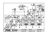
Repair manual3 - WIRING DIAGRAMS3.1 - ELECTRIC C<strong>AS</strong>INGS WIRING DIAGRAMS3.1.1 - Turntable box wiring diagram : P20593a :PORTE COFFRET / BOX DOOR INTERIEUR COFFRET / BOX INSIDE1 2TO CONNECTOR CNACONTROL POST SWITCHMDI6 5 3 2 13HVERS CONNECTEUR CN<strong>AS</strong>ELECTEUR DE POSTECODAGEWCODING6 5105CONTROL POST SWITCHSELECTEUR DE POSTE SA113AMOCONTROL POSTSWITCHCNA CNBCNDU VSELECTEUR DELIB.POSTE6 7 8 9 10W XR S TMAN COD SEL.CNCMDI6 5 3 2FROM CONTROL POST SWITCHDU SELECTEUR DE POSTEDE LA PORTE COFFRETFROM THE BOX DOORROUGE / REDBRANCHER ICI 107DE L INTERIEUR COFFRETSERIAL CARD BOTTOM CONTROL POST107CONNECT 107 HERE FROM INSIDE THE BOX2 3CARTE SERIELLE POSTE B<strong>AS</strong>107U3E.S.4 312 146 3137 CNA8 9 10MANA BA BC16260+12 (POINT MILIEU BAT) 1A1 L2 201 1B113CHARGEUR C16203C16258 M<strong>AS</strong>SE CH<strong>AS</strong>SIS 1A2101 1B2 CHARGERFCB MAT SQ427 42A 1B3C162064237K LM NO P1 8CNA2A4100 42A 2A52B425A 25FAISCEAU SB1 / SB1 BUNDLECOUPE-BATTERIE / BATTERY CUT OFFC162571 BRANCHER SUR 107DE LA PORTE COFFRETCONNECT TO 107 FROMTHE BOX DOOR10111213CABLAGE DEVERS SQ1 / TILT CABLING 14C162081536 2A72A842A 24SQ10 END OF TRAVEL -TOP- WIRING16CABLAGE FIN DE COURSE HAUT SQ10C1620517Q 5 3RS8PONT POUR SHUNTDU PRESSOSTATBRIDGE FOR PRESSURE SWITCHSHUNTA B10111213141524A 10010020021372B8 B-VARIATEUR / B-VARIABLE SPEED UNIT 18C16259192A1020AVERTISSEUR / BUZZER HA1 C162022A112122vers J4.2 PESAGE / TO J4.2 WEIGHINGRELAIS KA2 SURVOLTEUR / KA2 BOOSTER RELAY 23302485252216292610178627QR S T11PONT ENTRE COMMUNFIN DE COURSE B<strong>AS</strong> MATFIN DE COURSE B<strong>AS</strong> PENDBRIDGE BETWEEN COMMONEND OF TRAVEL BOTTOM M<strong>AS</strong>TEND OF TRAVEL TOP JIB181928TLEGENDE / LEGENDENTREE/SORTIE VAR / INPUT/OUTPUT VARDONNEES E/S TOURELLE / TURNTABLE INPUT/OUTPUTDATACODAGE / CODINGCABLAGE SPIRALE POSTE HAUT / B<strong>AS</strong>TOP/BOTTOM CONTROL POST SPIRAL WIRINGC16209A B3123303235A 35 3A33A434A 34 3A5STEERING POTENTIOMETERPOTENTIOMETRE DE DIRECTIONC1621028A2815A1A153A63A7BRAKING CONTROL / COMMANDE FREINSC16204ALARM INDICATOR HA C16209VOYANT ALARME HA C162091440A 403A183A17EV Yv1A C16193163B183A1917A 17EV Yv1B C1619418A 183A213A20EV Yv2A C1619520A 203B213A22EV Yv2B C161966A3B153A167A 7EV Yv3A C16197+ +3B273A288A 8EV Yv3B C161989A 93A243A23EV Yv4 C16199103A153A1411EV Yv6 C1620112A 123161UVX67891234504511783Q12345678991243612HIJ2v252311212HMOIJLNP365421123456789+++313++6+31212121212121212121212PENDULAIRE SB5JIBSB5ROTATIONSB7MAT SB6M<strong>AS</strong>T SB6107ANOIR / BLACKROSE / PINKJAUNE / YELLOWBLEU / BLUEGRIS / GREYORANGE9 10CNBSEL2444+12VGNDNCLTXDPCLTXDNCLRXDPCLRXD11CH<strong>AS</strong>SIS M<strong>AS</strong>SBRANCHER SUR FIL SPIRALE REP 16(PHARE DE TRAVAIL)CONNECT TO SPIRAL WIREMARK. 16 (FL<strong>AS</strong>HING LIGHT)J4TO 107 SWITCHBOX DOORVERS CONNECTEUR 107PORTE COFFRET87382638to /vers 38/J4.326to / vers 26/J4.5P20593a3 2 1 3 2 1WEIGHING CARDCARTE PESAGE J11 J153A113A263A27 KA 2: RELAIS SURVOLTEUR / KA2 BOOSTER RELAYVERS SURVOLTEURTO BOOSTER13
Repair manual3.1.2 - Platform box wiring diagram: P20027d100N EMB<strong>AS</strong>E 1 REP19A21A2 3 21A29A29A4 37A 37A5 1001006 1041057 1052008 2009 36A10 10611 +B212 SB213 +P214 SP215 40A16 107A171819 19A20 10421 36A22 10623 +B224 SB225 +P226 10027 SP240A107A20029a10537a10510040A107 ACNB421ACNB6CNBCN2CN1CNDCNCCNB3CNB7101Selection / Switch101101C de P101<strong>STAR</strong>TaaVOYANT HA / HA INDICATORa51315141ORIENTATIONDIRECTION / STEERINGAORANGEB GRIS / GREYC BLEU / BLUED JAUNE / YELLOWE ROSE / PINKF NOIR / BLACKG ROUGE / REDAvertisseur / Buzzer101BRANCHEMENT SUR PRISE 37 VOIESCONNECTION ON 37-PIN SOCKETP20027d4 5 2 51 53 5TRANSLATION / TRAVELAORANGEB GRIS / GREYC BLEU / BLUED JAUNE / YELLOWE ROSE / PINKF NOIR / BLACKG ROUGE / RED89The above diagrams along with the list of their components are included inthe spare parts manual.14
Repair manual3.2 - BUNDLE : DIAGRAM C16209Ref Qty Description Haulotte reference10 1 Electro head (delivered not fitted, tied on YV5 bundle) 24420091809 4 Cabling end fittings 24405022508 Cable 2*1mm2 according to specification N5074 24403114807 1 Cylindrical socket lug 24403055606 1 16 pin metal plug 24406038705 1 Adaptor 1 3/16-18 UNEF 24401063804 1 Thermoretractable sheath (0.31m) 24407017203 1 Polyflex 17 sheath 24407019402 2 Cabling end fittings 24405022501 1 Spiral cable according to specification N°5292 244031530015
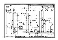
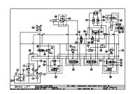
Repair manual3.3 - WIRING DIAGRAMS E555C3.3.1 - E555C-011 2 3 4 5 6 7 8 9 10 11 12 13 14 15 16 17 18 19 20 21ABCDEF220V5ARCH5AU1SA1CNB/QCNA/7Pendulaire JibMat MastCNB/SCNA/9QR S T6 7 8 9 10CNA/10U3CNB/ROrientationCNA/8CNB/T1Carte seriel Tourelle2 3 Turntable Serial card CNA/61ACNC/2CNC/3 CNC/1866876 67Descente ou GaucheDown or leftMontØe ou DroiteUp or rightSM1GHIJPB+KB-DeversTilt detectorLM250A254236243A17 3A19 3A20 3A22 3A16 3A28 3A23 2A18 3A1434 28U235PVMDI2 5 6 16 5 4 3 2Indicateur MDIMDI IndicatorPINGUELY-HAULOTTELa PØronniŁreBP 942152 L’HORMETEL: 04 77 29 24 24DESSINE PARF DØNØZØVERIFIE PARX MABBOUXDATE DE CREATIONIND DATE MODIFICATIONVISANBRE TOTAL DE FOLIOSE55519-06-2001 C 14-04-2004 Mise jour JEANNARD69<strong>STAR</strong> 8/10PBDATE DE VERIFICATIONA26-05-200321-02-2003PESAGEOption Phare de travailA. DUROA. DUROSCHEM<strong>AS</strong> EUROPE01453T1T2Pend > 0 / FcbContacteur Jib >0˚ / FcbMain ContactorFchDir droite IsolementSteering right IsolatingOrientation GOrientation leftSteeringpotentiometer2713PressostatShuntØPressure switchShunted2215 1F1F2Dir gaucheSteering leftOrientation DOrientation rightSignalMontee Pend ouDescente matUp jib orDown mastFreinsBrakesDØfreinageBrake ReleaseA2 A2A1 A1BUZZERMontee matUp mastMontee matUp mastMontee ou DescentependulaireUp or Down jibDescente matDown mastTractionSignalArret d’UrgenceD1 D1D2 D22620 6 7 8 18 12 9 19 173A18 3B18 3A21 3B21 3B15 3B27 3A24 2A17 3A152,5KOhm29 21 37413100SB1(01-9)102107AEmergencyStopPotentiometrede direction+12VGNDNCLTXDPCLTXDNCLRXDPCLRXD106L2102L4FU310AL4SB1381031002638L51001043A2711 403A263A11104201L2L1105100L410013A13A13A13A36A24A25A35A42A0L4L734A28A102100L1L11071071071A42A42A1005AL9100100L827A21A37A42A42A42A1A20A6A7A8A18A12A9A19A17AL10L61A1A107<strong>GB</strong>1RL2FU2RCH2FU5(2-4)(3-2)FU1R1<strong>GB</strong>210010010010040A11A1L4M1FU4(3-2)MD(3-2)MG(01-11)SQ12SQ10EGED(2-2)(01-15)YV1a YV1b YV2aP(2-2)RL1SQ1SQ4(01-2)B1D1(3-2)P1(2-2)YV2b(2-2)D210029A(2-2)(2-2)EFGEFDSB1aSB5SB6SB7(01-5)RL2RL1(3-11) (3-10)YV3aYV3b YV4 YV5 YV6RL316
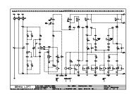
Repair manual3.3.2 - E555C-021 2 3 4 5 6 7 8 9 10 11 12 13 14 15 16 17 18 19 20A105105(01-10)BORIENTATION / DIRECTIONORIENTATION / STEERINGSM2 SM3TRANSLATION / ELEVATIONTRAVEL / LIFTINGCDEFHA HSSB3 SA2SA3X2SB8CNC2CNC4CNC1CN2 3CNB6CNB3CNB4CNB7CN1/2CN1/4CN1/5CN1/3CN1/1CN1/7CN1/9CN1/10CN1/8CN1/6DroiteGaucheRightLeftMarche arriŁre ou DescenteReverse gear or DownMarche avant ou MontØeForward or UpOption SurvolteurBooster optionG200CNC5105105105X1X1(01-18)40A29A37A29A21A29A10021A37A37A(01-21)(01-21)(01-21)(01-14)100X22P-T(3-19)(3-19)R2 R3SB9HI1 00 00 1Translation / DirectionTravel / SteeringMt / OrientationMast / OrientationPendulaireJib1 2 3 4 56 7 8 9 10U4Carte sØriel NacellePlatform Serial card100JKL(01-7)100107<strong>AS</strong>A4HPhX1X2Option Phare de travailWork headlight Option100100(3-16)100HA1MPINGUELY-HAULOTTELa PØronniŁreBP 942152 L’HORMETEL: 04 77 29 24 24DESSINE PARF DØNØZØVERIFIE PARX MABBOUXDATE DE CREATION19-09-2001DATE DE VERIFICATION01-01-2001E555<strong>STAR</strong> 8/10PIND DATE MODIFICATIONVISAC 14-04-2004 Mise jour JEANNARDBA26-05-200321-02-2003PESAGEOption Phare de travailA.DUROA. DURONBRE TOTAL DE FOLIOS69SCHEM<strong>AS</strong> EUROPE217
Repair manual3.3.3 - E555C-031 2 3 4 5 6 7 8 9 10 11 12 13 14 15 16 17 18 19 20 21AB(01-12)(01-11)+B2SB2CAPTEUR DEPRESSIONPESAGEWEIGHINGPRESSURESENSORB2C(01-14)100D(01-7)EFCAPTEUR D’ANGLEPESAGE(Potentiometre)WEIGHINGANGLE SENSOR(Potentiometer)P21071003826+B2SB2+P2SP2107+P2(2-13)100SP2J4.1 J4.2 J4.3 J4.5 J11.1 J11.3 J15.1 J15.3GJ4 J11 J15H6 5 43 2 1 3 2 13 2 1ICARTE PESAGEWEIGHING CARDJRL3(01-17)122P-TKLM(01-3)100(01-4)L4+-MARCHE / ARRETON / OFFPh1NOPTION SURVOLTEURBOOSTER OPTIONCOFFRET PROTECTIONPROTECTION BOX(2-12)(2-12)34PINGUELY-HAULOTTELa PØronniŁreBP 942152 L’HORMETEL: 04 77 29 24 24DESSINE PARDATE DE CREATIONIND DATE MODIFICATIONVISANBRE TOTAL DE FOLIOSE555Christophe Jey 29-06-2001 C 14-04-2004 Mise jour JEANNARD69<strong>STAR</strong> 8/10PB 26-05-2003 PESAGE A.DUROVERIFIE PARDATE DE VERIFICATIONSCHEM<strong>AS</strong> EUROPE318
Repair manual19
20Repair manual
Repair manual4 - SAFETY SYSTEMS4.1 - MACHINE ELEMENTSM1MDMGEFGEFDEDED4.1.1 - MotorsMotorpumpRight traction motorLeft traction motorLeft electro brakeRight electro brakeLeft energisingRight energisingFU1 1AFU2 5AFU3 10AFU4 250AFU5 5<strong>AS</strong>A1SA2SB1SB3SB5SB6SB7SB8SB9SM1SM2SM34.1.2 - Power supplies and fuses4.1.3 - Control inputsOverload protectionControl protectionElectrovalve protectionPower supply fuseWork headlight protection (option)Station selection switch (turntable panel)Movement selection switch (platform panel)Emergency stop ; line contactorEmergency stop ; platformJib control (turntable panel)Mast control (turntable)Turntable rotation controlPlatform movement validationHorn (platform)Turntable up/down, orientation manipulatorPlatform orientation, steering manipulatorPlatform travel manipulatorBrake release control (option)4.1.4 - Safety inputsSQ1TiltSQ4 Tilt reset / jib safety system > 0°SQ10Top end of travel safety sensor (mast)SQ12Tilt reset / Bottom end of travel safety sensor (mast)B2Pressure sensor (weighing)P1Steering potentiometerP2Angle sensor (weighing)RL1RL2RCH4.1.5 - RelaysOverload relay (inactive)Insulation relayInternal charger relay21
Repair manualYV1aYV1bYV2aYV2bYV3aYV3bYV4YV5YV6U1U2U3U44.1.6 - Electrovalve logic outputs4.1.7 - Management elementsRight steerLeft steerLeft orientationRight orientationJib up or mast downMast upMast upJib down or jib upMast downChargerChopperTurntable serial cardPlatform serial card4.1.8 - Sound indicatorH1PVHAHPh4.1.9 - Light indicatorsPlatform buzzerHourmeter : battery indicatorWeighing or tilt light indicatorWork headlight22
Repair manual5 - WEIGHING DEVICEWeighing system including :• - Electronic card – ref: 244 030 9330• - Angle sensor – ref: 244 030 9350• - Pressure sensor – ref: 244 030 9340• - Training control – ref: 244 030 93205.1 - FUNCTIONING PRINCIPLEElectronic card able to:• -detect a single and only threshold at 115% of nominal charge > Visualand sound signalling + cut off of all movements.• -transmit a piece of information to the chopper in order to slow downjib raising on reaching the upper stop so as to avoid abrupt stops.This device measures non-stop 2 physical values:• -the pressure in the jib cylinder’s chamber• -the chassis/jib angle.5.2 - WEIGHING CARDIt determines during a training test, the pressure normal value according tothe jib angle, without load and loaded at 115%. When detecting a pressurevalue which is too high compared to the one reported during the first testwith105% load, the system interprets it as an overload and gives the alarmto inform the user.5.2.1 - Characteristics2 outputs in order to obtain logical combinationsinterpreted by the chopper- J 4.3- J 4.5J11 : pressure sensor connectionJ15 : angle sensor connectionCard supply: 24VdcSupplied power: 4-20mA loop for pressure angle.5Vdc for angle sensor23
Repair manual5.2.2 - Environment• Varnished card: welding points are insulated.• Radiated emissions:- Radiated emissions must comply with the 95/54/CE Europeandirective.• Radiated sensitivity:- Radiated sensitivity must comply with ISO 11452-5 and ISO11452-2.5.2.2.1 -Climatic environment:The new system’s protective treatment must at least comply with the mostdemanding features defined by the TH indicator or Pinguely Haulotte’sdemands.• Temperature during use:-• Store temperature:• Maximum specific humidity:• Useful specific humidity:• Atmospheric pressure:• Saline fog:• Protection indicator:• Chemical aggression:• -40°C/+85°C (negotiable)• -40°C/+90°C• 39g water/kg dry air (+40°C / 80%HR)• +30°C +5°C / 60% +10% HR• 95000 Pa + 10000 Pa• Must resist saline fog as defined by:- 5% NaCI for 72 hours (NFX 41002)• IP67• The device must resist the following agents: Oil, gasoil,standard acids, solvents and stain removers,standard industrial cleaning products (acetone, whitespirit …), human perspiration, etc...5.2.2.2 -Mechanical environment:• Vibrations:- DIN IEC 68-2-34 (random vibrations), 2 hours in the threedirections of an orthostandardized system at 5.58 g, 50Hz to 200HZ.• Shocks- DIN IEC 68-2-27, 50g for 11m, 3 shocks in each direction of anorthostandardized system for a total of 18 shocks.24
Repair manual5.3 - CABLINGToppa-Card power supply:J4 connectorsJ4.1: + power supplyJ4.2: - power supplyJ4.3: chopper n°38inputJ4.4:Weighing cardChopperChassis control panelJ11J15Terminal Meaning Notes Terminal Meaning Notes1 Positive Red 1 Positive Red2 - Black 2 Negative Black3 4-20 mAsignalWhite 3 Sensor signal White5.4 - SENSORS5.4.1 - Pressure sensor• Operating pressure : 250 bars• Maximum pressure : 1500 bars• Output : 4-20mA• Power supply voltage rating : 9-34 Vdc• Precision : 9 - 34Vdc• Tolerated temperature range : -40°C / + 85°C• Protection grade : IP 67• Construction material : stainless steel5.4.2 - Angle sensor• Power supply : 5 to 30 Vdc• Maximum angle measured : 320°• Linearity : + 2.0% FS• Maximum power draw : 0.18 W• Resistance : 5 k Ohm• Working temperature : -20°C à 70°C• Standard connecting cable : approx. 4 m• Standard protection grade : IP 65• Weight : 0.25 kg.25
Repair manual5.5 - OUTPUTS FUNCTIONINGJ4.3: 3 state output >> 0V – 16V- 24VJ4.5: 2 state output >> 0V – 24VJ4.5 J4.30V 0V • Overload > 115%0V 16V • Impossible0V 24V • Low position end of travel : lowering forbidden24V 0V • Top position end of travel : raising forbidden24V 16V • Raising at low speed (ramp) : slow down threshold is reached.24V 24V • Normal functioningOverload always has priority.5.6 - TRAINING• 1.Read all the paragraphs listed below before starting the procedure.• 2.Cut off the card’s supply.• 3.Set the J14 adjustment jump.• 4.Remove all load from the platform.• 5.Switch the card on and wait for at least 15 seconds.• 6.Starting the adjustment phase: Press the SW2 button for at least3 seconds; the D20 red led comes on.• 7.Perform at least one complete raising/lowering cycle so as to bringthe oil to the normal temperature (ie as during operation).• 8.Activate the lowering control every now and then in order to completelydischarge the hydraulic pressure.• 9.Sensors’ zero: Press the SW3 button. Meanwhile, the green ledcomes on as confirmation.• 10.Maximum height acquisition: Activate the raising command andreach the top height – never stop activating the raising control in themean time.• 11.Press the SW1 rapidly (no longer than one second) so as to memorisethe maximum height. The yellow led comes on as confirmationwhile you press the button.• 12.Pression acquisition - unloaded: Activate the lowering controlup to the rest position. The system must stop at mid-height approximately.Keep activating the lowering control even during the momentaryinterruption.• 13.Load the adjustement weight (115% nominal charge).• 14.Static pressure values acquisition: Activate the raising controlup to the maximum height. The system will automatically perform intermediatestops.- Caution! Never activate the lowering control before reachingthe maximum height.• 15.Activate the lowering control and bring once more the platformback to the maximum height.• 16.Activate the descent control every now and then in order to completelydischarge the hydraulic pressure.• 17.Dynamic pressure values acquisition during lifting: Activatethe raising control up to the maximum height. Caution! Do not interruptthis phase!• 18.Dynamic pressure values acquisition during lowering: Activatethe lowering control and bring once more the platform back to themaximum height. Caution! Do not interrupt this phase!• 19.Towards the end of the lowering phase, the system automaticallygets out of the previous adjustements and the LD20 red led goes out.• 20.Switch the card off.26
Repair manual• 21.Remove the adjustment jump.• 22.Switch the system back on and check that it functions correctly:bring the system to give the alarm and check that the state of J4.3-J4.4 or J4.5-J4.6 changes. Also check that the system stops beforethe top and the low position end of travel.5.7 - ERRORS SIGNALLING5.7.1 - Sensors’ errors – D19 green LEDNumber of flashesMeaning- • No error.1 • Sensor n°1 line error (pressure transducer, J11 terminal block).2 • Sensor n°2 line error (angle transducer, J15 terminal block).3 • Pressure value is too low.4 • Angle value is too low.5 • Pressure value too low compared to the angle.6 • Pressure value too high at zero angle.5.7.2 - Card related errors – D21 yellow LEDNumber of flashesMeaning- • No error.1 • Card related error: Contact Pinguely-Haulotte.2 • Card related error: Contact Pinguely-Haulotte..3 • Check the connections polarity round the relays.4 • Angle value is too low.5 • Check that all the card’s inputs are connected to service positive inlets and notdirectly to the batteries’ positive.6 • Replace the card.5.8 - <strong>STAR</strong>S 8 AND <strong>STAR</strong>S 10 FUNCTIONINGLoad =115% Decelerationthreshold(before upper stop)The system worksproperly.All movements as well aslifting and lowering are cutoff. The buzzer sounds atregular intervals. The redlight indicator flashes.Lifting is performed atlow speed from thisthreshold up to thetop position end oftravel.Upper stop endof travelJib lifting isdeactivated.Lower stop end oftravelJib lowering isdeactivated.A few degrees (5 to 10°) before the upper stop, a logical combination onthe chopper’s inlets reports the deceleration for the jib raising instruction.(It is possible to adjust the threshold angle value through the RS232Cseries connection via PC, parameter: LIMSUP).Jib instruction speedJib deceleration speed = ----------------------------------------------227
Repair manualDeceleration thresholdDeceleration thresholdMechanicalstopsElectrical stops5.9 - ALARM SYSTEM MANAGEMENTTiltEUROPEOverloadRed light indicator • - • FlashesBuzzer • Continuous • IrregularNB: The overload alarm has priority before the tilt alarm.The functioning of the machine along with the weighing device is possiblethrough the following chopper software version: European versionTRIPLATB HU 1.06 >> TRI106B.28
Repair manual6 - ELECTRIC COMPONENTS POSITION6.1 - TURNTABLE CONTROL PANELSA1MDISB6 SB7 SB5 SM1Serial card 1A 1B 2A 2B 3A 3B1A 1B 2A 2B 3A 3B29
Repair manual• FU1 : • 1A Overload protection of the U2 card• FU2 : • 5A Protection of the U2 card controls• FU3 : • 10A Protection of the solenoid valve on U2 card• FU4 : • 250A power fuse• FU5 : 5A • Work headlight protection (option)• HA1 : • Warning signal 100/2A10, 200/2A11• M1 : • Pump motor• MDI : • Multifunction indicator• P1 : • Steering potentiometer 2.5 Ω• RCH : • Battery charger internal relay• RL1 : • Security relay fitted on the U2 card. Control of the overload pressure switch circuit.• RL2 : • Security relay fitted on the U2 card. Control of the chassis insulation from the machine.• SA1 : • Ignition key selector : command selection : either by the upside console or by the downside console• SB1 : • Electric equipment main switch.• SB5 : • Push button to command the jib. Input Q of the serial card.• SB6 : • Push button to command mast lifting. Input S of the serial card.• SB7 : • Push button to command the rotary motion. Input R of the serial card.• SM1 : • Orientation / lifting / jib joystick• SQ1 : • Tilt sensor 100/2A4, 25A/2A5, 42A/2B4• SQ10 : • Upper end of travel 42A/2A7, 24A/2A8• SQ4 : • Jib lower end of travel, tilt resetting.• SQ12 : • Mast lower end of travel, tilt resetting• U2 : • Interface card of the downside console• U3 : • Serial card of the upside console• YV1 : • Steering solenoid valve A = Right 20A / 3A17, B = Left 6A / 3A19 common 3A18 X2• YV2 : • Mast rotation solenoid valve. A= left 7A / 3A20, B=right 8A / 3A22 common 3A21X2• YV3 : • Up/Down Selection A=lifting of the jib or mast lowering 18A / 3A16 + 3B15,B= mast telescoping 12A / 3A28 + 3B27• YV4 : • Mast telescoping 9A/3A23 + 3A24• YV5 : • Jib lifting or lowering 19A / 2A18• YV6 : • Mast lowering solenoid valve17A / 3A14 + 3A1530
Repair manual6.2 - PLATFORM CONTROL PANELSB9SA2SM2 SB3 SM3 SB8• SA2 :• Motion selector CNB3 / 29A / CNB6• SB3 : • Platform emergency stop 37A / 105• SB8 :• Motion selection CNB4 / CNB7• SM2 :• Orientation / steering joystick• SM3 :• Travel / lifting joystick• SB9• Warning signal push button6.3 - JIBP2B2B2P2Angle sensor (weighing)Pressure sensor (weighing)31
Repair manual6.4 - CH<strong>AS</strong>SIS EQUIPMENTEFGEFDMDMGEFDEFGEGEDP1MG/EGMD/EDRight handside travel motorLeft handside travel motorRight travel motor electrobrakeLeft travel motor electrobrakeLeft handside travel motor inductorRight handside travel motor inductorSteering potentiometerBrakes connections :15A/3A6, 1A/3A732
Repair manual7 - OPERATING EQUATIONS7.1 - <strong>STAR</strong>T-UP7.2 - SHUTDOWNIf SB1=1 and RCH=0 and (SA1=turntable or (SA1=platform and SB3=1))then chopper activeIf SB1=0 or RCH=1 or (SA1=0 or (SA1=platform and SB3=0)) then chopperinactive7.3 - M<strong>AS</strong>T LIFTING7.3.1 - Turntable7.3.1.1 - UpIf SA1=turntable and SB6=1 and SM1=1 and (SQ1=1 or machineretracted) and overload =0 then YV3b=1 and YV4=1 and M1=1overload =1 if inputs 26=0 and 38=0 (26 and 38 ZAPI chopper inputs - 26:jib up blocking - 38: jib down blocking)Machine retracted -> SQ4=1 and SQ12=17.3.1.2 -DownIf SA1=turntable and SB6=1 and SM1=1 and overload =0 then YV3a=1and YV6=1 and M1=1overload =1 if inputs 26=0 and 38=0.Machine retracted -> SQ4=1 and SQ12=17.3.2 - Platform7.3.2.1 -UpIf SA1=platform and SB3=1 and SB8=1 and SA2=Mast and SM3=1 and(SQ1=1 or machine retracted and overload = 0 then YV3b = 1 andYV4=1 and M1=1overload =1 if inputs 26=0 and 38=0Machine retracted -> SQ4=1 and SQ12=17.3.2.2 -DownOverload =0 then YV3a=1 and YV6=1 and M1=1Overload =1 if inputs 26=0 and 38=0Machine retracted -> SQ4=1 and SQ12=17.4 - JIB7.4.1 - Turntable7.4.1.1 -UpIf SA1=turntable and SB5=1 and SM1=1 and (SQ1=1 or machineretracted) and overload =0 then YV3a=1 and YV5=1 and M1=1Overload=1 if inputs 26=0 and 38=0.Machine retracted -> SQ4=1 and SQ12=133
Repair manual7.4.1.2 -DownIf SA1= turntable and SB5=1 and SM1=1 and overload=0 then YV5=1overload=1 if inputs 26=0 and 38=0.Machine retracted -> SQ4=1 and SQ12=17.4.2 - Platform7.4.2.1 -UpIf SA1=platform and SB8=1 and SA2=jib and SM3=1 and (SQ1=1 ormachine retracted) and overload=0 then YV3a=1 and YV5=1 and M1=1overload=1 if inputs 26=0 and 38=0Machine retracted -> SQ4=1 and SQ12=17.4.2.2 -DownIf SA1=turntable and SB8=1 and SA2=jib and SM3=1 and overload=0 thenYV5=1overload=1 if inputs 26=0 and 38=0Machine retracted -> SQ4=1 and SQ12=17.5 - ROTATION7.5.1 - Turntable7.5.1.1 -LeftIf SA1=turntable and SB7=1 and SM1=1 and (SQ1=1 or machineretracted) and overload=0 then YV2a=1 and M1=1overload=1 if inputs 26=0 and 38=0Machine retracted -> SQ4=1 and SQ12=17.5.1.2 -RightIf SA1=turntable and SB5=1 and SM1=1 and (SQ1=1 or machineretracted) and overload=0 then YV2b=1 and M1=1overload=1 if inputs 26=0 and 38=0.Machine retracted -> SQ4=1 and SQ12=17.5.2 - Platform7.5.2.1 -LeftIf SA1=platform and SB8=1 and SA2=rotation andSM2=1 and (SQ1=1 ormachine retracted) and overload=0 then YV2a=1 and M1=1overload=1 if inputs 26=0 and 38=0Machine retracted -> SQ4=1 and SQ12=17.5.2.2 -RightIf SA1=turntable and SB8=1 and SA2=rotation and SM2=1 and (SQ1=1 ormachine retracted) and overload=0 then YV2b=1 and M1=1overload=1 if inputs 26=0 and 38=0.Machine retracted-> SQ4=1 and SQ12=134
Repair manual8 - MDI CONSOLE PROGRAMING PARAMETERS37
38Repair manual
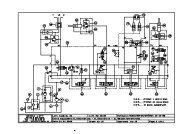
Repair manual9 - HYDRAULIC DIAGRAMS9.1 - HYDRAULIC INSTALLATION : A15007A150071/41/43/81/21/41/4S61224S1644S12S18 M18X150 M14 X1501/2 M22 X1501/2252845 47 4816464748S6S16M22 X150S163/8493/8S1652P T3/8S103/8S104 53/8S12503/817S6S10S10S63/8S6S6S6S6S16S18S18S181/21/2S63/82314 32 33 34 37142061511141S63/83/8S6S6S63/83/83/8S6S63/8S6S61732 34 3540 65101/4316528 211/21/2S16261/21638651531Collier fixationflexible rep. 7 /Fixing collar forhose marker 7224365196530 6636516442296017S1013626063S1053 54 55 56 57 58 59231896739
Repair manual10 - HYDRAULIC FUNCTIONING (B17085 DIAGRAM)10.1 - M<strong>AS</strong>T RAISING10.2 - M<strong>AS</strong>T LOWERING41
Repair manual10.3 - JIB LIFTING10.4 - JIB LOWERING42
Repair manual10.5 - TURNTABLE ROTATIONPositionvalve direction10.6 - STEERINGPossibledirections:right or left43
44Repair manual
Repair manual11 - POSITION OF HYDRAULIC COMPONENTS1 YV1 Steering electrovalve2 YV2 Turntable rotation motor electrovalve3 YV3 Pump flow accumulation electrovalve4 YV4 Electrovalve maintaining lifting or lowering movementsAt rest, lowering if YV6 = 15 YV5 Electrovalve selecting power supply.. At rest: powers the telescopic cylinder smallchamber feeding the mast; working, powers the jib.6 Position valve7 YV6 Electrovalve maintaining the lifting telescopic cylinder lowering movement.8 Main pressure regulating valve adjusted at 160 bars.9 Lifting pressure regulating valve adjusted at 45 bars.10 Emergency lowering manual tap11 YV6 Emergency lowering electrovalve12 Emergency pump13 Steering pressure regulating valve adjusted at 100 bars.2 :Orientation YV2a andYVb1 :Steering YV1a andYV1b4 :Mast raising YV4 +9 :Lifting pressureregulating valvePump coupling selectionand winder feedingcontrol (Jib + mastlowering control)3:YV3 a &YV3 b maximumpressure: 100bars2 :YV 2a1 :YV1a3 :YV3a1392 :YV 2a1 :YV 1a3 :YV3b4 :YV 4b45
Repair manual5710111246
Repair manual12 - S5682 HYDRAULIC BLOCK12.1 - CHARACTERISTICSDescription: Movement block <strong>STAR</strong> 8 10Haulotte ref : 242 021 286012.1.1 -Technical characteristicsMaximum pressure: 160barMax. flow: 22l/mm on the P and T line, useful load for mast raising.Max. flow: 10l/mm for all other movements.Temperature range: ambient: -20°C to +50°Chydraulic: -20°C to +80°CHydraulic characteristics: Mineral oil – viscosity grade 32cSt, 45cSt and68cSt.With biodegradable oil option: SHELL NATUREL HFEPorts: cylindric gasConnectors: ISO 4400 24V continuous currentHydraulic components will be delivered washed and rinsed, followingS5093 Pinguely Haulotte specification.12.1.2 -FttingsConnections should comply with S5470 Haulotte specification.The block must be delivered equipped with fittings tightened to theappropriate torque.The supplier selected for supplying fittings must be approved by PinguelyHaulotte.(Extract from R&D / FQ 01 15 A)47
Repair manual12.2 - DIAGRAMS48
Repair manual12.2.1 -List of componentsPosition Description Quantity1 Entry cap 3/8” gas + UMD1025/SB + RIT 12 Closing cap with P+T 3/8” gas 13 Mod. Solenoid valve ED1 3/8” 24 Mod. Solenoid valve ED1 3/8” 15 Mod. Solenoid valve ED2 3/8” 16 Modular element ED VM2 A 1F 27 O ring 108 O ring 49 Tie rod M8x245 310 Nut M8 Cl.10 311 Knurled washer M8 312 Kit screws and modular elements 1 EL. (N.4) M5x60 213 Push button manual overrride ED1 614 Plug DIN 908 3/8” gas 115 Washer 3/8“ gas 116 Push button manual override ED2 117 Washer ¼” gas 118 Pressure inlet ¼” BSPP 119 Union piece male 3/83” 120 Union piece male 3/83” G 521 Union piece male 3/83” G 222 Union piece male 3/83” G 249
50Repair manual
Repair manual13 - MAINTENANCE13.1 - GENERAL RECOMMENDATIONSServicing operation described in this manual are given for normalconditions of use.In difficult conditions: extreme temperatures, high hygrometry, pollutedatmosphere, high altitude, etc .... certains operations must be carried outmore frequently and specific precautions must be taken: consultPINGUELY-HAULOTYTE After-Sales Service for informationOnly authorised and competent personel may operate on the machine andmust comply with the safety instructions related to Personnel andEnvironment protection.Regularly check that the safety systems work properly.Caution!Do not use the machine as awelding earthDo not weld without disconnectingthe "+" and "-" terminals of thebatteriesDo not start other vehicles with thebatteries connected.IMPORTANT: REMOVE ALL COVERS BEFORE WORKING ON THETURNTABLE COMPONENTS.13.2 - PARTICULAR RECOMMENDATIONSBefore any maintenance intervention on the elevating platform, indicate onthe turntable and platform control stations that the machine is beingserviced. if possible, restrict access to the elevating platform to interventionpersonnel only.13.2.1 -Specific toolsPersonnel should therefore be familiar with the use of the specific toolsused (measurement device, torque tightening device, lifting apparatus, etcand respect the operating limits specified in the documentation that issupplied with the tools..Incorrect use of a tool (incorrect adjusment after a reading error) may leadto premature deterioration of the elevating platform (or more seruously, anaccident), for which PINGUELY-HAULOTTE cannot be held responsible.13.2.2 -Replacing an elementBefore replacing an element, the machine must be put in the maintenanceconfiguration (see corresponding paragraph) and the electric power supplycut off (see corresponding paragraph).All distributing valves are "with open centre" : breaking the electric circuittherefore decreases pressure in the hydraulic circuits, up to the non-returnvalves flanged on the cylinders. An element van be replaced safely, if theprocedures described in the maintenance sheets are respected (unscrewhydraulic connectors slowly to release residual pressure).To preserve the integrity of the safety systems ans the technicalcharacteristics of the elevating platform, it is essential to use original partsand to respect the initial setting and tightening torque value (seecorrespondning paragraph).51
Repair manual13.3 - MAINTENANCE SYSTEM13.4 - ELECTRIC POWER SUPPLY13.2.3 -Locating the breakdowncertains checks require the elevating platform to be switch on. In this case,personnel must ensure :• that the measurement devices used are properly insluated,• that they do not touch the live parts,• that they are not wearing or carriyng metal objects that may deterioratethe live components (e.g.: dropping a spanner during an interventionon the batteries).Maintenance configuration• Position the elevating platform on a firm, horizontal surface.• If possible, fold the machine completely.InstructionsCutting off the electric power supply :Press the turntable emergency stop (ref. 1 Photo. 1, page 52).Photo 1 . Restoring the electric power supply :Reset the emergency stop (Photo. 1, page 52).152
Repair manual13.5 - MAINTENANCE PLANThe plan on the following page gives the frequency, servicing operations(device) and consumables to be used.• The reference in the symbol indicates the servicing point according tofrequency.• The symbole represents the consumable to be used.13.5.1 -Consumable.INGREDIENT SPECIFICATION SYMBOLHydraulic oilAFNOR 48 602ISO VG 46Lubricantsused byHAULOTTEBPSHF ZS 46ELFHYDRELFDS46TOTALEQUI-VISZS 46Extreme pressure lithiumgreaseISO - XM - 2CARDREXA-DC 1Lead-free grease Grade 2 or 3ESSOGPGRE<strong>AS</strong>EMULTIMOTIVE2MULTISEP 2Exchange or specificoperationHigh pressurelubricantORGANIC hydraulicoil(OPTION)BARDAHLSUPERTEFLUBE +PTFEExtreme coldhydraulic oil(OPTION)AFNOR 48 602ISO VG 32SHELLTELLUS T-3253
Repair manual13.5.2 -Maintenance plan54
Repair manual13.5.3 -OPERATIONSIMPORTANT: IF ORGANIC OR EXTREME COLD OILS ARE USED, THEPERIODICITIES IN THE TABLE BELOW ARE REDUCED BY HALF.PERIODICITY OPERATION REFERENCEEvery day or beforeeach start of operationsEvery 50 hoursEvery 250 hoursEvery 500 hoursEvery 1000 hoursEvery 2000 hoursCaution!It is essential to use the lubricantsmentioned in the consumables tableChap. 2.2.1, page 49 as dust sticksto standard grease.•·Check:- hydraulic tank level. See chap. 4.3.3.- electrolyte level in the batteries.See chap. 4.3.3.• Grease:- wheel pivot pins.- ring: bearing.- ring: teeth.CAUTIONafter first 50 hours:• Change the hydraulic filter cartridge.See chap. 5.3.1. (see 250 hoursperiodicity)• Check tightness of slew ring screws.(see 500 hour periodicity)• ·Change the hydraulic filter cartridgeSee chap. 5.3.1.• ·Grease the friction parts of the mast,check pad wear.• Check the tightness of- wheel nuts.- upper clevis screws• Check the tightness of the ringscrews.• If using organic oil, empty the hydraulicoil tank.• Empty the hydraulic oil tank (capacity25 l).See chap. 5.3.3.• Empty the hydraulic oil tank and thewhole circuit See chap. 5.3.3.124563710891112131413.6 - PRESENCE OF LABELSMake sure that the labels and plates informing personnel of the variousdangers related to machine use are in good condition.The labels also inform operators on the use and maintenance of themachine.An illegible label may result in incorrect or dangerous use of the machine.Instructions:Check that the labels are present:Check that all the labels described in the operator’s manual are legible andin place. Replace if necessary (additional copies can be supplied onrequest).55
Repair manual13.7 - PRESENCE OF MANUALSIt is important to ensure that the manuals supplied with the machine are ingood condition and stored in the document holder provided on the platform.An illegible manual may lead to incorrect or dangerous use of the machine.Instructions:Check that the manuals are present:Check that the manuals are legible, complete and stored in the documentholder provided on the platform. Replace if necessary (extra copies can besupplied on request by the manufacturer).56
Repair manual 314 -PREVENTIVE MAINTENANCE SHEETSList of preventive maintenance sheets:Sheet no.P003P005P006P010P011DescriptionLubricating the steering wheel pivotsChecking - filling the hydraulic oil tankChanging the hydraulic filter cartridgeChecking - servicing the traction batteriesLubricating the mast55
563 Repair manual
SHEET P003PREVENTIVE MAINTENANCE SHEETGRE<strong>AS</strong>ING THE STEERING WHEEL PIVOTSSheet 1/11 - Greasing the steering wheel pivots•Cut off the electric power supply (see § 6.3, page 26).•Grease the pivots.NOTA :Only use the grease recommended by the manufacturer.Compact, optimum, previousdesign.•Put the machine back into the operational configurationCompact, optimum, currentdesignStar 22J / Star 8
PREVENTIVE MAINTENANCE SHEET
Sheet P005PREVENTIVE MAINTENANCE SHEETCHECKING / FILLINGTHE HYDRAULIC OIL TANKFolio 1/11 - Preliminary operations• Put the machine in the maintenance configuration (see corresponding paragraph).• Switch off electric power (see corresponding paragraph).2 - Checking - filling the hydraulic oil tankNB:This operation must be carried out when the oil is cold, i.e. before startingthe machine.• Check that the level of oil (1) in the tank is between the high and low levelswhen cold.• Top up if necessary, by filling via the cap (2).NB:Only use the oil recommended by the manufacturer.21• Put the machine back into the operational configuration.HA16/18PX - HA46/51JRT1 221Star 22 J / Star 8HA16/18PX New DesignHA46/51JRT New Design21
PREVENTIVE MAINTENANCE SHEET
PREVENTIVE MAINTENANCE SHEETSheet P006CHANGING THE HYDRAULIC FILTERFolio 1/1CARTRIDGECaution!Use a container to collect oilto prevent pollution of theenvironment.2 - Preliminary operations• Put the machine in the maintenance configuration (see corresponding paragraph).• Switch off electric power (see corresponding paragraph).2 - Replacing the hydraulic filter cartridgeNB:The filter has a clogging indicator. Clogging should be checked whenthe machine is hot, otherwise, the indicator may be visible due to theviscosity of the cold oil.2• Change the cartridge (1) if the clogging indicator appears (2).• Unscrew the base nut (3) and remove the cartridge from the hydraulic filter.• Screw a new cartridge into place.• Put the machine back into the operational configuration.1 2113HA16/18 PXHA46/51JRTHA20/26 PXHA61/80JRT32<strong>STAR</strong> 22 J / Star 8HA12IP - HA33JE3113H14P / H16TPHB40/44JHA15I - HA43E
PREVENTIVE MAINTENANCE SHEET
PREVENTIVE MAINTENANCE SHEETSheet P010 Folio 1/2CHECKING / SERVICING THE TRACTION BATTERIESCaution!These operations requiresafety precautions (weargloves and protectivegoggles).Caution!Do not electric arc weld on themachine without firstdisconnecting the batteries.Caution!Do not use the batteries tojump start another vehicle.1 - Preliminary operations• Put the machine into the maintenance configuration (see relevant section).2 - Battery servicing• Check the electrolyte levels before charging once a week in normal use.• If necessary, top up:- with distilled or de-mineralised water,- after charging.• No not add acid (in the event of spillage, contact our After-sales department).• Do not leave discharged batteries idle.• Avoid overflow.• Clean the batteries to avoid salt formation and current deviation.• Wash the top without removing the caps.• Dry with compressed air or clean cloths.• Grease the lugs.NB:To enable rapid diagnosis of the state of your batteries, note the densityof each element once a month, using a battery hydrometer, as a functionof temperature, using the graph below (do not measure directly afterfilling.Fahrenheit- 158-152-143-136-120-107-104-87-80-77-73-68-60-57-53-51-50-46C- 70- 67- 62- 58- 49- 42-40-31-27-25-23-20-16-14-12-11-10-81.301.291.281.271.261.251.241.231.221.211.201.191.181.171.161.151.141.131.121.111.10STOP !Do not recharge Recharge RECHARGEIMMEDIATELY59 Fahrenheit /1586 Fahrenheit / 3113 Fahrenheit / 4100 %80 %60 %40 %20 %0 %Electrolyte freezing point in Fahrenheit / ˚Cfor densities noted at 86 Fahrenheit / 30˚State of charge of a battery as a function of density and temperature
PREVENTIVE MAINTENANCE SHEETSheet P010 Folio 2/2CHECKING / SERVICING THE TRACTION BATTERIES
PREVENTIVE MAINTENANCE SHEETSHEET P011 Folio 1/1LUBRICATING THE M<strong>AS</strong>T1 - Lubricating the mast• Extend the mast.• Switch off the electric power supply (see relevant section).• Grease the slides, at pad level, using a spatula.• Grease the pads at the back of the machine.NB:Only use lubricants recommended by the manufacturer.• Put the machine back into the operational configuration.
PREVENTIVE MAINTENANCE SHEET
Repair manual15 - OPERATING INCIDENTSREMINDER:Respecting the machine’s operating and servicinginstructions will enable you to avoid most incidents.However, certain incidents may arise and before any intervention, it isessential to consult table 6.1. If the incident is listed, simply follow theinstructions.Only common incidents whose solutions can be implemented by anoperator are listed. For all other incidents, contact your PINGUELYHAULOTTE representative or the plant’s After-sales service.Before diagnosing a failure, check that:• the emergency stop "palm buttons" on the turntable and platform areunlocked• the circuit breakers on the turntable panel are pushed in.The speed chopper has a failure indication system on the timer display. Todiagnose a failure, consult the table below, note the alarm code and passit onto the After-sales service, who will given you the instructions to follow.57
15.1 - TROUBLE-SHOOTINGCODE ALARM PROBABLE CAUSES REMEDIESRepair manual1POWER FAILURE• Short-circuit on an on/off valve: proportionalelectrovalve, coil main contactor SB1 orelectrobrake.2 EEPROM KO• Failure in the memory area in which theconfigured parameters are stored. If the failureremains when the ignition key has been turned onand then off, change the EEPROM. If the alarmstops, the stored parameters may have beencancelled and replaced by default parameters.• Replace the chopper.3INCORRECT<strong>STAR</strong>T• Forward/reverse gear / jib lowering or lifting /platform lifting or lowering / left/right / steering/traction authorization is/are ON when the ignitionkey is turned off or traction is required beforetraction authorization occurs.• Machine problem, contactAfter-Sales service.4CAPACITORCHARGE5 R VMN NOT OK6 L VMN NOT OK7 VACC NOT OK• The test is executed during the initial diagnosis.The alarm switches on if, 500 m after the ignitionkey has been turned off, condensers have notstarted to load. A probable reason for that is adefault in the power unit.• The test is executed at rest, main switch off, andduring operation. If the VMN is inferior to the batteryvoltage, and the machine is at rest, then the chopperswitches to an alarm state. While working, thealarm switches ON if the VMN does not follow theduty-cycle of the chopper.• Possible reasons:- Incorrect motor connection- Current leakage to the ground- Default in the power unit.• The test is executed at rest, main switch off, andduring operation. If the VMN is inferior to the batteryvoltage, and the machine is at rest, then the chopperswitches to an alarm state. While working, thealarm switches ON if the VMN does not follow theduty-cycle of the chopper.• Possible reasons:- Incorrect motor connection- Current leakage to the ground- Default in the power unit.• The alarm shows that the traction acceleratorvoltage received by the serial card is more than 1Vat rest, without any operation request.• Possible reasons (to look for in the serial card):- One of the potentiometer’s wires is cut.- The potentiometer is improperlyconnected.- The potentiometer is defective.- Incorrect serial card programming.• Replace the chopper.• Check the right travelmotor and its wiring (sock).• If they are correct, replacethe chopper.• Check the left travel motorand its wiring (sock).• If they are correct, replacethe chopper.• The code checks thepotentiometer voltage valueat rest.• Replace the serial card orthe joystick.58
Repair manualCODE ALARM PROBABLE CAUSES REMEDIES8 VFIELD NOT OK• The test is executed at rest. In this condition, thevoltage on the 2 connections of the field should beabout half of the batteries’. The alarm is given ifvoltage is different from this value.• Possible reasons for voltage differences:- Motor current leakage to the ground.- The field of the motor is not connected tothe chopper.- Default in the section of the power unitrelated to the field.• Check the travel motor’sinductors and check the F1and F2 outputs’ resistancecompared to positive andnegative outputs.9STEER SENSORKO• The µP maintains that the signal of the steeringpotentiometer is not out of the programmed range.• Possible reasons for failure:- Incorrect programming- Steering potentiometer needs readjusting.• Check the potentiometer,wiring, chopper data (steersensor adjusting).10RIGHT STBY IHIGHLEFT STBY IHIGH• The test is executed during the initial diagnosis, atrest. It maintains that the current is superior to aminimum threshold. In the opposite case, thechopper switches the alarm ON while blocking themachine.• Possible reasons for failure:- Sensor is out of order.- Fault in the measure circuit, the logiccircuit, or in the power.• Induction current problemdetected on ignition.• Replace the chopper.11RIGHT I = 0 EVERLEFT I = 0 EVER• The test is executed while working. It checks thatthe current is superior to a threshold value. In theopposite case, the chopper switches the alarm ONwhile blocking the machine.• Possible reasons: see STBY HIGH.• Induction current problemdetected during operation.• Replace the chopper.12HIGH FIELDCURRENT• Malfunction in the field current. The field current atrest is not nil.• Possible reasons for failure to indicate nil fieldcurrent:- Malfunction in the current detector- Fault in the power unit of the field.• Inductor current problemdetected on ignition.• Replace the chopper.13NO FIELDCURRENT• Malfunction in the field current. While working thefield current is nil• Possible reasons:- Malfunction in the current detector- Fault in the power unit.• Inductor current problemdetected on ignition.• Replace the chopper.14DRIVERSHORTED• The test is executed with the main switch (SB1)open. Check that the main switch driver is not inshort-circuit.• Possible reasons for failure:- Driver in short-circuit.- Malfunction in the measure circuit of thecontactor coil voltage.- Incorrect wiring.- Faulty hardware circuit protection (NotaBene: This alarm is normally overridden byalarm #1 POWER FAILURE).• Main switch alarm usuallyoverridden by the POWERFAILURE alarm.• Machine related problem ;contact After Sales Service.59
Repair manualCODE ALARM PROBABLE CAUSES REMEDIES15CONTACTORDRIVER• The test is executed while the main switch isclosed. It checks that the driver is not open.• Possible reasons for failure:- Short-circuit in the driver.- Malfunction in the circuit of the contactorcoil voltage.• Alarm given on SB1 driver(main switch in shortcircuit).• Replace the chopper.16CONTACTORCLOSED• The test is executed each time before the mainswitch is closed. It checks that the switch is actuallyopen.• Possible reasons for failure:- The switch contacts are stuck.- A malfunction in the power unit.• Alarm given due to aproblem on the SB1 powercontact.• Replace the power sensoror the chopper.• Check F1 and F2 on thechopper.17 FORW + BACK18 BATTERY LOW• The test is performed non stop. The alarm is on iftwo requests for different operations aresimultaneously activated.• Possible reasons:- Mistake in wiring.- Working microswitch stuck.- Wrong operation by the user.• Stepping down of the traction current and blockingof the pump functions. The battery alarm switcheson when there is 10% of residual load left.• If the alarm is on with unloaded batteries, controlthe battery value read in the TESTER menu of theconsole. If incorrect, adjust it in the menu CONFIGMENU/ADJUSTMENT.• Replace the serial card orjoystick.• Fix the problem selectingthe BATT ADJUSTMENTfunction. It is essential totest the travel movementsBEFORE replacing thechopper.19BRAKE DRIVERKO• This alarm is on when there is a problem on theelectrobrake driver.• Possible reasons:- Short-circuit in the driver- Defect in the driver unable to command theelectrobrake.- The measure circuit on the voltage on theelectro-brake coil is defective.• Internal problem related tothe chopper QH20 driver.• Replace the chopper.20CONTACTOROPEN• The control microprocessor is broken or hasidentified a dangerous situation that has not beendetected by the main microprocessor.• Replace the chopper.21MICRO CONTROLKO• The µP of the logic control is broken or severalconnections have been damaged.• Replace the chopper.22CHECK UPNEEDED• Servicing request programmed ; interval of thelast maintenance operation >300h. This alarmdoes not stop the machine but signals the problem.Select the option "CHECK UP DONE" ON to erasethe message.• Cancel the servicingrequest, reset or service themachine if needed.23 NO ISOLATION• Maintains that the chassis is not on short circuitwith the +BATT or connected to the ground.• Check the circuit and thechopper’s outputsinsulation.• Repair the damagedcircuit.60
Repair manualCODE ALARM PROBABLE CAUSES REMEDIES24PRESSURE NOTOK• The pressure switch can be damaged ordisconnected or the emergency stop could havebeen damaged (it cuts the positive charge at thepressure switch but not at the logic).• Check the shunt on theserial card and that thevoltage on the chopperinput is positive.25CHOPPER NOTCONFIGURATED• A valid model for the chopper has not beenconfigured. (See the model selection board).• Check the parameters(shunt on the downside ofthe serial card).26 EVP NOT OK• The proportional electrovalve is open at rest.While working, the electrovalve is too open or tooclosed compared to the PVM applied.• Check that the controllerhas been correctlyconfigured with absentEVP.27SERIAL ERROR#1• Incomplete or lack of reception by the selectedserial card.• Check the serial cardselection by SA1.28THERMALPROTECTION• Heat alarm > 75°C/167°F ; the maximum currenton inductors is linearly stepped down to 0 at 90°C/194°F. The alarm stops if T
Repair manualANOMALY PROBABLE CAUSE SOLUTIONNo jib up/down movement from theplatformNo jib up/down movement from theturntableNo mast up/down movement fromthe platformNo mast up/down movement fromthe turntableNo right/left rotation movementfrom the platformNo right/left rotation movementfrom the turntable• Defective wiring• Defective serial board• Defective manipulator SM3• Defective fail-safe pedal• Defective SB5• Defective or discharged batteries• Defective chopper• Defective coil• Defective wiring• Defective selector switch• Defective serial board• Defective manipulator SM1• Defective fail-safe pedal• Defective or discharged batteries• Defective chopper• Defective coil• Defective SB5• Defective wiring• Defective selector switch• Defective serial board• Defective manipulator SM3• Defective fail-safe pedal• Defective SQ10• Defective or discharged batteries• Defective chopper• Defective coil• Defective wiring• Defective serial board• Defective manipulator SM1• Defective SB6• Defective SQ10• Defective or discharged batteries• Defective chopper• Defective coil• Defective wiring• Defective selector switch• Defective serial board• Defective manipulator SM2• Defective fail-safe pedal• Defective chopper• Defective coil• Defective wiring• Defective serial board• Defective manipulator SM1• Defective SB7• Defective SQ10• Defective chopper• Defective coilSheet DP075Sheet DP076Sheet DP077Sheet DP078Sheet DP079Sheet DP08062
Repair manualANOMALY PROBABLE CAUSE SOLUTIONNo movement available from theplatformNo movement available from theturntableNo forward or back travelmovementTravel only in microspeedNo right or left steering movement• Defective fuses• Defective wiring• Defective emergency stop button or station selection• Defective chopper• Defective serial board• Defective manipulator SM2• Defective fail-safe pedal• Defective SB contactor• Defective or discharged batteries• Defective fuses• Defective emergency stop button or station selection• Defective chopper• Defective serial board• Defective manipulator SM1• Defective SB contactor• Defective wiring• Defective or discharged batteries• Defective wiring• Defective selector switch• Defective manipulator SM3• Defective fail-safe pedal• Defective serial board• Defective chopper• Defective wiring• Defective chopper• SQ12 incorrectly set or defective• SQ4 incorrectly set or defective• Defective wiring• Defective selector switch• Defective manipulator SM2• Defective fail-safe pedal• Defective chopper• Defective coilSheet DP081Sheet DP082Sheet DP083Sheet DP084Sheet DP08563
64Repair manual
Sheet DP075BREAKDOWN DETECTION FLOW CHARTNO UP OR DOWN JIB MOVEMENTFROM THE PLATFORMFolio 1/6No jib up or down movement from theplatformPut the key switch in the“Turntable” position.Activate jib movementThe jib movesup or downNOBYESPut the key switch in the “Platform”position. Activate jib movementOpen the “Platform” box andmeasure voltage on CN23 andCNB6 of the platform boardCN23 = 0 VCNB6 = 24 VNOYESMeasure voltage at theterminals of selectorswitch SA2<strong>AS</strong>A2a (29A)= 0 VSA2b = 24 VYESRepair wiringNOReplace theselectorSee sheetC004END
Sheet DP075BREAKDOWN DETECTION FLOW CHARTNO UP OR DOWN JIB MOVEMENTFROM THE PLATFORMFolio 2/6AMeasure voltage on CN1/9, CN1/10 and CN1/8 on the platformboardCN1/8=0V idleCN1/8=0V at 4VCN1/10=5V & CN1/9=0V (up)CN1/10=0V & CN1/9=5V(down)YESNOFollow the same wire colours andmeasure voltage at the terminalsof manipulator SM3Measure voltage at CNB4CNB4 = 24 VNO0V < cursor < 4VFOR contact = 5V orREV contact= 5VNOYESYESReplace manipulatorSM3See sheetC142Replace the SerialboardSee sheetC063Repair the wiringENDMeasure voltage at pedal outputVoltage measured =24 VYESRepair the wiringNOReplace the pedalSee sheetC064END
Sheet DP075BREAKDOWN DETECTION FLOW CHARTNO UP OR DOWN JIB MOVEMENTFROM THE PLATFORMFolio 3/6No down movementBNo up movementCheck battery chargeBattery chargeOKNOYESPut the key switch in the“Platform” position and activatejib movementCharge the batteriesSee sheetC139No down movementNo up movementThe pump worksNOYESMeasure voltage at terminals(18) and (19) of thechopperCheck pump wiringWiring is correctNONO(18) = 24V/104 (up)(19) = 24V/104 (up/down)YESReplace the chopperSee sheetC003YESReplace the chopperSee sheetC003Repair the wiringCEND
Sheet DP075BREAKDOWN DETECTION FLOW CHARTNO UP OR DOWN JIB MOVEMENTFROM THE PLATFORMFolio 4/6CMeasure voltage at theterminals of electrovalvesYV3a and YV5NOYV3a = 24 V (up)andYV5 = 24 V (up/down)Repair the wiringbetween the chopperand the electrovalvesYESReplace the coilSee sheetC145ENDThe problempersistsNOENDYESD
Sheet DP075BREAKDOWN DETECTION FLOW CHARTNO UP OR DOWN JIB MOVEMENTFROM THE PLATFORMFolio 5/6DConnect a pressure gauge tothe pressure tapping at smallpump output.Make a jib up/downmovementPressure= 2320 PSI / 160barsYESNOReplace electrovalveYV5See sheetC067NOPressure zeroYESTest or replace theSee sheet2320 PSI / 160 barsC218pressure limitersReplace electrovalveYV3See sheetC067
Sheet DP075BREAKDOWN DETECTION FLOW CHARTNO UP OR DOWN JIB MOVEMENTFROM THE PLATFORMFolio 6/6
Sheet DP076BREAKDOWN DETECTION FLOW CHARTNO UP OR DOWN JIB MOVEMENTFROM THE TURNTABLENo jib up or down movement from theturntableFolio 1/6Put the key switch in the“Platform” position.Activate jib movementThe jib movesup or downNOBYESPut the key switch in the“Turntable” position. Activate jibmovementOpen the “Turntable” box andmeasure voltage on CNA/10,CNA/8 and CNA/9 of the turntableboardA
Sheet DP076BREAKDOWN DETECTION FLOW CHARTNO UP OR DOWN JIB MOVEMENTFROM THE TURNTABLEFolio 2/6ACNA/8=0V idleCNA/8=0V at 4VCNA/10=5V & CNA/9=0V(up)CNA/10=0V &CNA/9=5V(down)NOYESFollow the same wire colours andmeasure voltage at the terminalsof manipulator SM1Measure voltage at CNB/QCNBQ = 24 VNO0V
Sheet DP076BREAKDOWN DETECTION FLOW CHARTNO UP OR DOWN JIB MOVEMENTFROM THE TURNTABLEFolio 3/6No down movementBNo up movementCheck battery chargeBattery chargeOKNOYESPut the key switch in the“Turntable” position and activatejib movementCharge the batteriesSee sheetC139No down movementNo up movementThe pump worksNOYESMeasure voltage atterminals (18) and (19) ofthe chopperCheck pump wiringWiring is correctNONO(18) = 24V/104 (up)(19) = 24V/104 (up/down)YESReplace the chopperSee sheetC003YESReplace the chopperSee sheetC003Repair the wiringCEND
Sheet DP076BREAKDOWN DETECTION FLOW CHARTNO UP OR DOWN JIB MOVEMENTFROM THE TURNTABLEFolio 4/6CMeasure voltage at theterminals of electrovalvesYV3a and YV5NOYV3a = 24 V (up)andYV5 = 24 V (up/down)Repair the wiring betweenthe chopper andthe electrovalvesYESReplace the coilSee sheetC145ENDThe problempersistsNOENDYESD
Sheet DP076BREAKDOWN DETECTION FLOW CHARTNO UP OR DOWN JIB MOVEMENTFROM THE TURNTABLEFolio 5/6DConnect a pressure gauge onthe pressure tapping at smallpump output.Make a jib up/downmovementPressure= 2320 PSI / 160barsYESNOReplace electrovalveYV5See sheetC067NOPressure zeroYESTest or replace the2320 PSI / 160 barspressure limitersSee sheetC218Replace electrovalveYV3See sheetC067
Sheet DP076BREAKDOWN DETECTION FLOW CHARTNO UP OR DOWN JIB MOVEMENTFROM THE TURNTABLEFolio 6/6
Sheet DP077BREAKDOWN DETECTION FLOW CHARTNO UP OR DOWN M<strong>AS</strong>T MOVEMENTFROM THE PLATFORMFolio 1/6No mast up or down movement from theplatformPut the key switch in the“Turntable” position.Activate mast up/downmovementThe mast movesup or downNOBYESPut the key switch in the “Platform”position. Activate mast up/downmovementOpen the “Platform” box and measurevoltage on CN23 and CNB6of the platform boardCN23 = 0VCNB6 = 0VNOYESMeasure voltage at theterminals of selectorswitch SA2<strong>AS</strong>A2a (29A) = 0VSA2b = 0VNOYESRepair the wiringReplace theselectorSee sheetC004END
Sheet DP077BREAKDOWN DETECTION FLOW CHARTNO UP OR DOWN M<strong>AS</strong>T MOVEMENTFROM THE PLATFORMFolio 2/6AMeasure voltage at CN1/9, CN1/10 and CN1/8 on the platformboardCN1/8=0V idleCN1/8 = 0V at 4VCN1/10=5V & CN1/9=0V(up)CN1/10=0V & CN1/9=5V(down)YESNOFollow the same wire colours andmeasure voltage at the terminalsof manipulator SM3Measure voltage at CNB4CNB4 = 24 VNO0V
Sheet DP077BREAKDOWN DETECTION FLOW CHARTNO UP OR DOWN M<strong>AS</strong>T MOVEMENTFROM THE PLATFORMFolio 3/6BNo down movementNo up movementMeasure voltage atterminal 24 of the chopperVoltage measured =24 VNOYESCheck if the mast is at itsmax. heightDMax. height reachedYESNOLower the mastMeasure voltage at SQ10SQ10 = 24VNOYESRepair the wiringReplace the sensorSee sheetC200END
Sheet DP077BREAKDOWN DETECTION FLOW CHARTNO UP OR DOWN M<strong>AS</strong>T MOVEMENTFROM THE PLATFORMFolio 4/6DNo down movementNo up movementCheck battery chargeBattery chargeOKNOYESPut the key switch in the“Platform” position and activatemast movementCharge the batteriesSee sheetC139No down movementNo up movementThe pump worksNOYESCheck pump cablingMeasure voltage atterminals (9), (12), (17)and (18) of the chopperNO(17), (18) =24V/104 (down)(9), (12) = 24V/104 (up/down)Wiring is OKYESNOReplace the chopperSee sheetC003YESReplace the chopperSee sheetC003Repair the wiringCEND
Sheet DP077BREAKDOWN DETECTION FLOW CHARTNO UP OR DOWN M<strong>AS</strong>T MOVEMENTFROM THE PLATFORMFolio 5/6CMeasure voltage at theterminals of electrovalvesYV3a, YV3b, YV4 & YV6NOYV3a and YV424 V (up) andYV3b and YV6 =24 V (down)Repair the wiringbetween the chopperand the electrovalvesYESReplace the coilSee sheetC145ENDThe problempersistsNOENDYESD
Sheet DP077BREAKDOWN DETECTION FLOW CHARTNO UP OR DOWN M<strong>AS</strong>T MOVEMENTFROM THE PLATFORMFolio 6/6DConnect a pressure gauge tothe pressure tapping at smallpump output.Make a mast up/downmovementPressure= 1450 PSI/ 100 barsNONo down movementYESReplace electrovalveYV4See sheetC067No down movementYESPressurezeroNOTest or replace the1450 PSI / 100 barsand 2320 PSI / 160bars pressure limitersSee sheetC218Replace electrovalveYV3See sheetC067Manually test electrovalveYV3Operation correctNOManually test electrovalveYV6YESTest or replace the652 PSI / 45 barspressureSee sheetC218Operation correctNOReplace electrovalveYV3See sheetC067YESReplace electrovalveYV6See sheetC067Replace electrovalveYV5See sheetC067
Sheet DP078BREAKDOWN DETECTION FLOW CHARTNO UP OR DOWN M<strong>AS</strong>T MOVEMENTFROM THE TURNTABLEFolio 1/6No mast up or down movement from theturntablePut the key switch in the“Platform” position.Activate mast up/downmovementThe mast movesup or downNOBYESPut the key switch in the“Turntable” position. Activate mastup/down movementOpen the “Turntable” box andmeasure voltage at CNA/8, CNA/9and CNA/10 of the turntable boardA
Sheet DP078BREAKDOWN DETECTION FLOW CHARTNO UP OR DOWN M<strong>AS</strong>T MOVEMENTFROM THE TURNTABLEFolio 2/6ACNA/8=0V idleCNA/8=0V at 4VCNA/10=5V & CNA/9=0V(up)CNA/10=0V & CNA/9=5V(down)NOYESFollow the same wire colours andmeasure voltage at the terminalsof manipulator SM1.Measure voltage at CNB/SCNB/S = 24 VNO0V
Sheet DP078BREAKDOWN DETECTION FLOW CHARTNO UP OR DOWN M<strong>AS</strong>T MOVEMENTFROM THE TURNTABLEFolio 3/6BNo down movementNo up movementMeasure voltage atterminal 24 of the chopperVoltage measured =24 VNOYESCheck if the mast hasreached its max. heightDMax. height reachedYESNOLower the mastMeasure voltage at SQ10SQ10 = 24VNOYESRepair the wiringReplace the sensorSee sheetC200END
Sheet DP078BREAKDOWN DETECTION FLOW CHARTNO UP OR DOWN M<strong>AS</strong>T MOVEMENTFROM THE TURNTABLEFolio 4/6DNo down movementNo up movementCheck battery chargeBattery chargeOKNOYESPut the key swith in the“Turntable” position and activatemast movementCharge the batteriesSee sheetC139No down movementNo up movementThe pump worksNOYESCheck pump wiringMeasure voltage atterminals (9), (12), (17)and (18) of the chopperNO(17), (18) =24V/104 (down)(9), (12) = 24V/104 (up/down)Wiring is correctYESNOReplace the chopperSee sheetC003YESReplace the chopperSee sheetC003Repair the wiringCEND
Sheet DP078BREAKDOWN DETECTION FLOW CHARTNO UP OR DOWN M<strong>AS</strong>T MOVEMENTFROM THE TURNTABLEFolio 5/6CMeasure voltage at theterminals of electrovalvesYV3a, YV3b, YV4 & YV6NOYV3a and YV424 V (up) andYV3b and YV6 =24 V (down)Repair the wiringbetween the chopperand the electrovalvesYESReplace the coilSee sheetC145ENDThe problempersistsNOENDYESD
Sheet DP078BREAKDOWN DETECTION FLOW CHARTNO UP OR DOWN M<strong>AS</strong>T MOVEMENTFROM THE TURNTABLEFolio 6/6DConnect a pressure gauge tothe pressure tapping at smallpump output.Make a mast up/downmovementPressure= 1450 PSI100 barsNo down movementYESNOReplace electrovalveYV4See sheetC067No down movementPressure zeroYESNOTest or replace the1450 PSI / 100 barsand 2320 PSI / 160bars pressure limitersSee sheetC218Replace electrovalveYV3See sheetC067Manually test electrovalveYV3Operation correctNOManually test electrovalveYV6YESTest or replace the652 PSI / 45 barspressure limitersSee sheetC218Operation correctNOReplace electrovalveYV3See sheetC067YESReplace electrovalveYV6See sheetC067Replace electrovalveYV5See sheetC067
Sheet DP079BREAKDOWN DETECTION FLOW CHARTNO RIGHT OR LEFT ROTATIONAL M<strong>AS</strong>T MOVEMENTFROM THE PLATFORMFolio 1/6No mast right or left rotation movementfrom the platformPut the key switch in the“Turntable” position.Activate the right/left rotationmovementRight/leftrotationmovement OKNOBYESPut the key switch in the “Platform”position.Activate mast right/left rotationmovementOpen the “Platform” box andmeasure voltage at CN23 andCNB6 of the platform boardCN23 = 0VCNB6 = 0VNOYESMeasure voltage at theterminals of selectorswitch SA2<strong>AS</strong>A2a (29A) = 0VSA2b = 0VNOYESRepair the wiringReplace theselectorSee sheetC004END
Sheet DP079BREAKDOWN DETECTION FLOW CHARTNO RIGHT OR LEFT ROTATIONAL M<strong>AS</strong>T MOVEMENTFROM THE PLATFORMFolio 2/6AMeasure voltage at CN1/4, CN1/5 and CN1/3 on the platformboardCN1/3=0V idleCN1/3=0V at 4VCN1/5=5V & CN1/4=0V (up)CN1/5=0V & CN1/4=5V(down)YESNOFollow the same wire colours andmeasure voltage at the terminalsof manipulator SM2Measure voltage at CNB4CNB4 = 24 VNO0V
Sheet DP079BREAKDOWN DETECTION FLOW CHARTNO RIGHT OR LEFT ROTATIONAL M<strong>AS</strong>T MOVEMENTFROM THE PLATFORMFolio 3/6BPut the key switch in the“Platform” position and activateright/left rotation movementThe pump worksNOYESCheck pump wiringMeasure voltage atterminals (7) and (8) ofthe chopperNO(7) =24V/104 (left)(8) = 24V/104 (right)Wiring is correctYESNOReplace the chopperSee sheetC003YESReplace the chopperSee sheetC003Repair the wiringCEND
Sheet DP079BREAKDOWN DETECTION FLOW CHARTNO RIGHT OR LEFT ROTATIONAL M<strong>AS</strong>T MOVEMENTFROM THE PLATFORMFolio 4/6CMeasure voltage at theterminals of electrovalvesYV2a and YV2bNOYV2a = 24 V (left)andYV2b = 24 V(right)Repair the wiringbetween the chopperand the electrovalvesYESReplace the coilSee sheetC145ENDThe problempersistsNOENDYESD
Sheet DP079BREAKDOWN DETECTION FLOW CHARTNO RIGHT OR LEFT ROTATIONAL M<strong>AS</strong>T MOVEMENTFROM THE PLATFORMFolio 5/6DConnect a pressure gauge tothe pressure tapping at smallpump output.Make a right/left rotationmovementPressure= 1450 PSI /100 barsNOYESReplace electrovalveYV2See sheetC067Test or replace the1450 PSI / 100 barsand 2320 PSI / 160bars pressure limitersReplace the rotationmotorSee sheetC218 orsheetC205
Sheet DP079BREAKDOWN DETECTION FLOW CHARTNO RIGHT OR LEFT ROTATIONAL M<strong>AS</strong>T MOVEMENTFROM THE PLATFORMFolio 6/6
Sheet DP080BREAKDOWN DETECTION FLOW CHARTNO RIGHT OR LEFT ROTATIONAL M<strong>AS</strong>T MOVEMENTFROM THE TURNTABLEFolio 1/6No mast right or left rotation movementfrom the turntablePut the key switch in the“Platform” position.Activate mast right/left rotationmovementRight/leftrotationmovement OKNOBYESPut the key switch in the“Turntable” position.Activate mast right/left rotationmovementOpen the “Turntable” box andmeasure voltage at CNA/8, CNA/9and CNA/10 of the turntable boardA
Sheet DP080BREAKDOWN DETECTION FLOW CHARTNO RIGHT OR LEFT ROTATIONAL M<strong>AS</strong>T MOVEMENTFROM THE TURNTABLEFolio 2/6ACNA/8=0V idleCNA/8=0V at 4VCNA/10=5V & CNA/9=0V (up)CNA/10=0V & CNA/9=5V(down)YESNOFollow the same wire colours andmeasure voltage at the terminalsof manipulator SM1Measure voltage at CNB/R0V < cursor < 4VFOR contact = 5Vor REV contact = 5VNOCNB/R = 24 VYESNOYESReplace manipulatorSM1See sheetC143Replace the SerialboardSee sheetC063Repair the wiringENDMeasure voltage at SB7 outputSB7 = 24 VYESRepair the wiringNOReplace the buttonSee sheetC004END
Sheet DP080BREAKDOWN DETECTION FLOW CHARTNO RIGHT OR LEFT ROTATIONAL M<strong>AS</strong>T MOVEMENTFROM THE TURNTABLEFolio 3/6BPut the key switch in the“Turntable” position and activatemast movementThe pump worksNOYESCheck pump wiringMeasure voltage atterminals (7) and (8) of thechopperWiring is correctNONOReplace the chopperSee sheetC003(7) = 24V/104(left)(8) = 24V/104(right)YESYESReplace the chopperSee sheetC003Repair the wiringCEND
Sheet DP080BREAKDOWN DETECTION FLOW CHARTNO RIGHT OR LEFT ROTATIONAL M<strong>AS</strong>T MOVEMENTFROM THE TURNTABLEFolio 4/6CMeasure voltage at theterminals of electrovalvesYV2a and YV2bNOYV2a = 24 V (left)andYV2b = 24 V(right)Repair the wiringbetween the chopperand the electrovalvesYESReplace the coilSee sheetC145ENDThe problempersistsNOENDYESD
Sheet DP080BREAKDOWN DETECTION FLOW CHARTNO RIGHT OR LEFT ROTATIONAL M<strong>AS</strong>T MOVEMENTFROM THE TURNTABLEFolio 5/6DConnect a pressure gauge tothe pressure tapping at smallpump output.Make a left/right rotationmovementPressure= 1450 PSI / 100barsNOYESReplace electrovalveYV2See sheetC067Test or replace the1450 PSI / 100 barsand 2320 PSI / 160bars pressure limitersReplace the rotationmotorSee sheetC218 orsheetC205
Sheet DP080BREAKDOWN DETECTION FLOW CHARTNO RIGHT OR LEFT ROTATIONAL M<strong>AS</strong>T MOVEMENTFROM THE TURNTABLEFolio 6/6
Sheet DP081BREAKDOWN DETECTION FLOW CHARTNO MOVEMENT AVAILABLE FROM THEPLATFORMNo movement availablefrom the platformFolio 1/4Put the key switch in the“Platform” position.Activate a movementNo movement ismadeNOAYESCheck fuses FU1, FU2, FU4 andFU5Replace anydefective fusesNOFuses OKYESENDMake sure that the emergencystop and station selection buttonsare operationalButtons OKNOReplace anydefective buttonsSee sheetC004YESMeasure voltage at terminals (5)and (42) of the chopperEND24V OKNOReplace the chopperSee sheetC003YESBEND
Sheet DP081BREAKDOWN DETECTION FLOW CHARTNO MOVEMENT AVAILABLE FROM THEPLATFORMFolio 2/4AMeasure voltage at CNB4CNB4 = 24 VNOYESReplace the SerialboardSee sheetC063Measure voltage at pedal outputVoltage measured= 24 VYESRepair the wiringNOReplace the pedalSee sheetC064END
Sheet DP081BREAKDOWN DETECTION FLOW CHARTNO MOVEMENT AVAILABLE FROM THEPLATFORMFolio 3/4BMeasure voltage at the terminalsof contactor SB1 (L3)24 V OKYESNOCheck the wiring andbatteries.If necessary, repairthe wiring and/orreplace the batteriesSee sheetC149Replace contactor SB See sheetC200
Sheet DP081BREAKDOWN DETECTION FLOW CHARTNO MOVEMENT AVAILABLE FROM THEPLATFORMFolio 4/4
Sheet DP082BREAKDOWN DETECTION FLOW CHARTNO MOVEMENT AVAILABLE FROM THE TURNTABLEFolio 1/4No movement availablefrom the turntablePut the key switch in the“Turntable” position.Activate a movementNo movementis madeNOAYESCheck fuses FU1, FU2, FU4 andFU5Fuses OKYESNOReplace anydefective fusesENDCheck that the emergency stopand station selection buttons areoperationalYESButtons OKNOReplace anydefective buttonsSee sheetC004YESMeasure voltage at terminals (5)and (42) of the chopperEND24V OKNOReplace the chopperSee sheetC003YESENDB
Sheet DP082BREAKDOWN DETECTION FLOW CHARTNO MOVEMENT AVAILABLE FROM THE TURNTABLEFolio 2/4AOpen the “Turntable” box andmeasure voltage at CNA/10,CNA/9 and CNA8 of the turntableboardCNA/8=0V idleCNA/8=0V at 4VCNA/10=5V and CNA/9=0V(up)CNA/10=0V and CNA/9=5V(down)YESNOFollow the same wire colorsand measure voltage at theterminals of manipulator SM1Replace the SerialboardSee sheetC0630V< cursor
Sheet DP082BREAKDOWN DETECTION FLOW CHARTNO MOVEMENT AVAILABLE FROM THE TURNTABLEFolio 3/4BMeasure voltage at the terminalsof contactor SB1 (L3)24 V OKYESNOCheck the wiring andthe batteries.If necessary, repairthe wiring and/orreplace the batteriesSee sheetC149Replace contactor SB See sheetC200
Sheet DP082BREAKDOWN DETECTION FLOW CHARTNO MOVEMENT AVAILABLE FROM THE TURNTABLEFolio 4/4
Sheet DP083BREAKDOWN DETECTION FLOW CHARTNO FORWARD OR REVERSE TRAVEL MOVEMENTFolio 1/4No forward or reverse travel movementfrom the platformPut the key switch in the“Platform” position.Activate FOR and REV travelOpen the “Platform” box andmeasure voltage at CN23 andCNB6 of the platform boardCN23 = 24VCNB6 = 0VNOYESMeasure voltage at theterminals of selectorswitch SA2<strong>AS</strong>A2a (29A)= 24VSA2b = 0VNOYESRepair the wiringReplace theselectorSee sheetC143END
Sheet DP083BREAKDOWN DETECTION FLOW CHARTNO FORWARD OR REVERSE TRAVEL MOVEMENTFolio 2/4AMeasure voltage at CN1/8, CN1/9 and CN1/10 on the platformboardCN1/8 = 0V idleCN1/8 = 0V at 4VCN1/10=5V & CN1/9=0V(up)CN1/10=0V & CN1/9=5V(down)YESNOFollow the same wire colors andmeasure voltage at the terminalsof manipulator SM3Measure voltage at CNB4CNB4 = 24 VNO0V
Sheet DP083BREAKDOWN DETECTION FLOW CHARTNO FORWARD OR REVERSE TRAVEL MOVEMENTFolio 3/4BMeasure voltage at terminals (1)and (15) of the chopper(1) = 24 Vand (15) = 24 VNOYESMeasure voltage directlyon the brakesReplace the SerialboardSee sheetC063NO24VOKYESRepair the wiringbetween the brakesand the chopperENDReplace the chopperSee sheetC003
Sheet DP083BREAKDOWN DETECTION FLOW CHARTNO FORWARD OR REVERSE TRAVEL MOVEMENTFolio 4/4
Sheet DP084BREAKDOWN DETECTION FLOW CHARTTRAVEL MOVEMENT IN MICROSPEED ONLYFolio 1/2Travel movement in microspeed onlyPut the key switch in the “Platform”position. Retract the mast and jibcompletelyMeasure voltage at terminal (36)of the chopper(36) = 24 VNOYESMeasure voltage at theterminals of SQ12(wire 36A)Replace thechopperSee sheetC00324 VOKYESNOVisually check that SQ12is closedRepair wiring betweenSQ12 and chopperENDSQ12 is closedNOYESAdjust or replace thesensorSee sheetC200A
Sheet DP084BREAKDOWN DETECTION FLOW CHARTTRAVEL MOVEMENT IN MICROSPEED ONLYFolio 2/2AMeasure voltage at the terminalsof SQ4 (wire 106)24 V OKYESNOVisually check that SQ4is closedRepair the wiring between SQ4and SQ12SQ4 is closedNOENDYESAdjust or replace thesensorSee sheetC200Repair the wiring betweenSQ4 and 42AEND
Sheet DP085BREAKDOWN DETECTION FLOW CHARTNO LEFT OR RIGHTSTEERING MOVEMENTFolio 1/4No left or right steering movement fromthe platformPut the key switch in the “Platform”position.Activate left or right steeringOpen the “Platform” box andmeasure voltage at CN23 andCNB6 of the platform boardCN23 = 24VCNB6 = 0VNOYESMeasure voltage at theterminals of selectorswitch SA2<strong>AS</strong>A2a (29A)= 24VSA2b = 0VNOYESRepair the wiringReplace theselectorSee sheetC004END
Sheet DP085BREAKDOWN DETECTION FLOW CHARTNO LEFT OR RIGHTSTEERING MOVEMENTFolio 2/4AMeasure voltage at CN1/3, CN1/4 and CN1/5 of the platformboardNOCN1/3=0V idleCN1/3=0V at 4VCN1/5=5V &CN1/4=0V (up)CN1/5=0V &CN1/4=5V(down)Follow the same wire colors andmeasure voltage at the terminalsof manipulator SM2YESMeasure voltage at CNB40V
Sheet DP085BREAKDOWN DETECTION FLOW CHARTNO LEFT OR RIGHTSTEERING MOVEMENTFolio 3/4BThe pump worksNOYESCheck pump wiringMeasure voltage atterminals (6), (12) and(20) of the chopperNOReplace the chopper(6) =24V/104 (right)(12) = 24V/104 (left/right)(20) = 24V/104(left)See sheetC003YESWiring OKYESReplace the chopperNOSee sheetC003Repair the wiringCEND
Sheet DP085BREAKDOWN DETECTION FLOW CHARTNO LEFT OR RIGHTSTEERING MOVEMENTFolio 4/4CMeasure voltage at theterminals of electrovalvesYV1a, YV1b and YB3bNOYV1a = 24 (right)YV1b = 24 (left) andYV3a = 24 V (left/right)Repair the wiringbetween the chopperand the electrovalvesYESReplace the coilSee sheetC145ENDThe problempersistsNOENDYESConnect a pressure gauge onthe pressure tapping at smallpump output.Make a steering movementPressure= 1450 PSI /100 barsYESReplace electrovalveYV1NOSee sheetC067Test or replace the1450 PSI / 100 bars See sheetand 2320 PSI / 160 C218bars pressure limiters
Repair manual16 - CORRECTIVE MAINTENANCE PROCEDUREList of corrective maintenance sheets:Sheet no.C003C004C010C040C060C063C067C139C140C141C142C143C144C145C146C147C148C149C198C200C201C202C203C204C205C206C207C208C209C210C211C212C213C214C215DescriptionReplacing the chopperReplacing a component of the platform control stationReplacing a hoseReplacing the hornReplacing the hand pumpReplacing the printed circuitReplacing an electrovalveCharging the traction batteriesReplacing the tilt sensorReplacing the jib cylinderReplacing the top panel manipulatorReplacing the bottom panel manipulatorReplacing a steering wheelReplacing a coilReplacing the steering potentiometerReplacing the coversReplacing the hydraulic winderReplacing the batteriesDismantling - reassembling the mastReplacing an end of travel contactorReplacing the hydraulic filterReplacing the hydraulic blockReplacing the motor pump unitReplacing the hydraulic pumpReplacing the rotation motorReplacing a drive wheelReplacing the hydraulic tankReplacing the turntable emergency stop buttonReplacing the battery chargerReplacing the slew ringReplacing a steering pivotReplacing a steering cylinderReplacing the counterweightsReplacing the electric plateReplacing the jib-platform assembly65
Repair manualSheet no.C216C217C218DescriptionRemoving - reinstalling the cable sleeveReplacing a wheel reducer or a hydraulic travel motorAdjusting a pressure limiter66
SHEET C003CORRECTIVE MAINTENANCE SHEETREPLACING THE SPEED VARIATORSheet 1/21 - Preliminary operations•Put the machine in the low position.•Cut off the electric power supply (see § 6.3, page 26).•Disconnect the + and - terminals of the batteries to isolate the electric circuit.2 - Removing the speed variator•Disconnect the speed variator’s electric connections.•Remove the speed variator (1).Compact3 - Replacing the speed variator•Put the speed variator back into place and secure with the fixing screws.•Reconnect the speed variator’s electric connections.•Reconnect the + and - terminals of the batteries.•Put the machine back in the operational configuration.•1Optimum1OptimumCompact
SHEET C003CORRECTIVE MAINTENANCE SHEETREPLACING THE SPEED VARIATORSheet 2/2Star 22 J / Star 811HA12IP / HA33JE
CORRECTIVE MAINTENANCE SHEETSHEET C004REPLACING A COMPONENT ON THESheet 1/1PLATFORM CONTROL PANEL1 - Preliminary operations• Cut off the electric power supply (see § 6.3, page 26).Caution!Do not use the machineduring maintenanceoperations.2 - Removing a component from the platform control panel• Remove the closing plate (1) by unscrewing the four fixing screws.• Mark and disconnect the electric connections of the component to bereplaced.• Remove the component.3 - Replacing a component on the platform control panel• Put a new component and seal into place on the front of the platform controlpanel.NB:If it is a lever switch, adjust the position of the fixing nut and counternut so that the switch lever joint axle is on the same level as the seal,to ensure tightness.1Compact - Optimum• Reconnect the electric connections according to the marks made whendismantling.• Fix the closing plate with the four fixing screws.• Perform the function corresponding to the replaced component to checkthat it works properly.1Star 8 - HM10P (star 10)
CORRECTIVE MAINTENANCE SHEET
Sheet C010CORRECTIVE MAINTENANCE SHEETREPLACING A HYDRAULIC HOSEFolio 1/1Caution!Ensure that the oil is not toohot.1 - Preliminary operations• Put the machine in the maintenance configuration (see § 6.3, page 48).• Switch off the electric power supply (see § 6.4, page 49).• If necessary, close the shut-off valve or empty the hydraulic tank.2 - Removing a hydraulic hose• Disconnect the hose from the equipment to which it is connected.NB:Unscrew the hose slowly to release residual hydraulic pressure.Caution!Use a container to collect theoil to avoid pollution of theenvironment.• Protect the equipment holes with caps.3 - Remounting a hydraulic hose• Reconnect a new hydraulic hose (§ 2.3.4 - Tightening torque of hydraulichoses, page 16).• Put the machine back in the operational configuration.• Make a few movements implementing the hose in question to purge thehydraulic circuit.• Check the level of the hydraulic oil tank.
CORRECTIVE MAINTENANCE SHEETSheet C040 Sheet 1/1CHANGING THE HORNCaution!Do not use the machineduring maintenanceoperations.1 - Preliminary operations• Switch off electric power (see corresponding paragraph).2 - Removing the horn• Mark and disconnect the electric connections from the horn (1).• Remove the horn, by unscrewing the fixing bolts (2).213 - Installing the horn• Put the horn back into place and fix with the fixing bolt.• Reconnect the electric connections according to the marks made duringdismantling.4 - Test• Select the top control panel and switch on machine power.• Put the machine back into the operational configuration.• Activate the horn switch from the platform control panel and check that thehorn sounds.HA16 - PX / HA18 PX / HA 465 RT2 1Star 22J / Star 8Caution!The horn should be audiblefrom the basket.12HA12IP - HA33JE
CORRECTIVE MAINTENANCE SHEET
CORRECTIVE MAINTENANCE SHEETSheet C060 Sheet 1/1CHANGING THE HAND PUMPCaution!Use a container to collect oilto prevent pollution of theenvironment.1 - Preliminary operations• Put the machine in the maintenance configuration.2 - Removing the hand pump• Mark and disconnect the hydraulic hoses (2) from the hand pump (1).NB:Unscrew the hoses slowly to release residual hydraulic pressure.415• Fit caps to the hoses.• Remove the union pieces (3) from the hand pump.• Remove the hand pump by removing its fixing bolts (5).43 - Installing the hand pump• Put a new hand pump into place and fix using the fixing bolts.• Replace the non-return valve (6) if necessary.• Install the union pieces on the pump.• Reconnect the hydraulic hoses, according to the marks made during dismantling.• Put the machine back into the operational configuration.• Close the decompression valve (4).• Perform an emergency operation to check that the hand pump works properly(see «Operation and Maintenance Instructions» manual).• Open the decompression valve.4 15 4 6562 3HA16 PX - HA18 PX / HA 465 RT12 323Star 22 J / Star 8HA12IP / HA33JE
CORRECTIVE MAINTENANCE SHEET
Sheet C063CORRECTIVE MAINTENANCE SHEETCHANGING THE PRINTED CIRCUITSheet 1/13 241 - Preliminary operations• Put the machine in the maintenance configuration (see correspondingparagraph).• Switch off electric power (see corresponding paragraph).• Disconnect the « - » then « + » terminals of the starter battery.2 - Removing the printed circuit• Open the turntable electric box.• Carefully mark and disconnect all the electric connections (1) of the printedcircuit (2).• Remove the U1 electronic module (4) (except <strong>STAR</strong>, HA12IP andHA33JE) (see corresponding sheet)• Remove the bolts (3) fixing the board to the box and their sealing washers.• Remove the printed circuit and silent-blocks equipping the fixing bolts.• <strong>STAR</strong> only : disconnect the printed circuit’s serial card.HA16 PX - HA18 PX / HA 465 RT3 213 - Installing the printed circuit• Put a new printed circuit into place and fix using the bolts equipped withsilent blocks, sealing rings and new toothed washers.• <strong>STAR</strong> only : Install the printed circuit’s serial card.• Install the U1 electronic module (except <strong>STAR</strong>, HA12IP and HA33JE)(see corresponding sheet).• Reconnect the electric connections according to the marks made duringdismantling.• Close the turntable box.• Reconnect the « + » then « - » terminals of the starter battery.• Put the machine back into the operational configuration.• Test the printed circuit.4 - Testing the printed circuit• Perform the computer operating test (see «changing the U1 electronicmodule» sheet) (except <strong>STAR</strong>, HA12IP and HA33JE).1 2 3 1 2 31Star 22J / Star 8HA12IP-HA33JEHA15I-HA43E
CORRECTIVE MAINTENANCE SHEET
Sheet C067CORRECTIVE MAINTENANCE SHEETCHANGING AN ELECTROVALVESheet 1/2Caution!Ensure that the oil is not toohot.Caution!Use a container to collect oilto prevent pollution of theenvironment.3HA16 PX - HA18 PX / HA 465 RT1121 - Preliminary operations• Put the machine in the maintenance configuration (see correspondingparagraph).• Switch off electric power (see corresponding paragraph).2 - Removing an electrovalve• Mark and disconnect the electric connections(1) of the coils.• Mark the installation position of the electrovalve on the block.• Unscrew the four fixing screws (3) of the electrovalve (2) and remove.3 - Installing an electrovalve• Put a new electrovalve equipped with its seals into place and fix using the4 screws, in the position of the electrovalve on the block. Tighten to therecommended torque (see corresponding paragraph).• Reconnect the electrovalve’s electric connections, according to the marksmade during dismantling.• Put the machine back into the operational configuration.• Make several movement cycles using the replaced electrovalve to purgethe hydraulic circuit.• Check the level of the hydraulic oil tank.4 - Dismantling/ reassembling an Oil Control coil• Mark and disconnect the electric connections of the coils (4).• Remove the protection (5) (plastic cap) from the end of the coil.• Unscrew the nut (6) holding the coil and remove.• Put a new coil into place.• Put back the nut, protection and then reconnect the electric connections.5 - Dismantling/reassembling an Oil Control slide valveThe whole section (7) must be replaced, not just the slide valve(mark the defective sections in the stack).• Disconnect the wiring harnesses and the hydraulic hoses (plug them toprevent contamination).• Remove the nuts (8) from the end of the three assembling tie rods (9).• Remove the sections (7) one by one until the defective section is reached.• Put a new section into place, then reassemble all sections.78 95 64Star 22 J / Star 8Star 8 / Star 22J• Put the nuts back into place (tightening torque 20 / 21 N.m or 14.75 /15.49 lb.ft).Throughout the dismantling/reassembly operation, take great care topreserve cleanliness and place the seals correctly at the interfaces betweensections.
CORRECTIVE MAINTENANCE SHEET
CORRECTIVE MAINTENANCE SHEETSheet C139 Sheet 1/2CHARGING THE TRACTION BATTERIESCaution!Do not use the machineduring the charging process.Caution!Use the machine’s on-boardcharger. Its charge output issuited to the machine.Caution!Safety precautions arerequired for batteryservicing operations (weargloves and protectivegoggles).1 - Preliminary operations• Ensure that the mains supply is suitable for the charger’s consumption andvoltage.• Fill to the minimum electrolyte level if an element’s level is below this minimum.• Work in a clean, ventilated area, away from naked flames.2 - Charging the batteriesNB:Charging starts automatically as soons as the mains supply is connected.For information: charging time for a battery discharged by 80% isapproximately 15 hours.• Connect the plug (2) to the mains (110V for USA).• Check the charge state on the light (3) on the bottom control panel.- Red zone: machine charging- Yellow zone: 80% of charging complete- Green zone: batteries charged231Star 8 / Star 22JStar 8 / Star 22J
CORRECTIVE MAINTENANCE SHEETSheet C139 Sheet 2/2CHARGING THE TRACTION BATTERIES32HA12IP - HA33JE3 - During charging• Do not remove or close the element caps.• Ensure that element temperature does not exceed 45°C (be careful in summeror in rooms with high ambient temperature).4 - After charging• Top up the electrolyte level if necessary.4 - Additional operations• Put the machine back into the operational configuration.
CORRECTIVE MAINTENANCE SHEETSheet C140 Sheet 1/1REPLACING THE TILT SENSORCaution!Do not use the machineduring maintenanceoperations.1 - Preliminary operations• Put the machine on a flat, level surface.• Put the machine in the maintenance configuration (see relevant section).• Switch off the electric power supply (see relevant section).2 - Removing the tilt sensor• Mark and disconnect the electric connections of the tilt sensor.• Remove the tilt sensor (2) by unscrewing the fixing bolts (1).233 - Re-installing the tilt sensor• Put a new tilt sensor into place and secure with the fixing bolts (1).• Reconnect the electric connections according to the marks made duringdismantling.• Set the adjusting screw (4) so that the tilt sensor level is set.• Put the machine back into the operational configuration.4 - Tilt sensor operating test• Extend the machine.• Tilt the tilt sensor and check that an audible alarm is sounded.• Make mast up and jib lifting movements to the safety contacts.14
CORRECTIVE MAINTENANCE SHEET
Sheet C141CORRECTIVE MAINTENANCE SHEETCHANGING THE JIB CYLINDERSheet 1/1Caution!Ensure that the oil is not toohot.1 - Preliminary operations• Put the machine in the maintenance configuration (see relevant section).• Switch off the electric power supply.• Put the basket in slings to ensure it does not fall (Photo 1) and secure it.• Slightly lift the drum to facilitate access to the cylinder.2 - Removing the jib cylinder• Put the cylinder (1) and the vertical parts (2) and (3) of the jib into slings.• Mark and disconnect the 2 hydraulic hoses of the jib cylinder.NB:Unscrew the hoses slowly to release residual hydraulic pressure.• Put caps on the hoses.• Remove the 2 bolts of the cylinder pin (4) on the cylinder body side.• Remove the pin (4).• Remove the 2 bolts of the cylinder pin (5) on the rod side.• Remove the pin (5).• Remove the jib cylinder (1).3 - Reinstalling the jib cylinderPhoto 1NB:Before reassembly, check the condition of all articulated pin rings,and replace if necessary. Lubricate all bores before reinstalling thepins. Only use lubricants recommended by the manufacturer.• Put the jib cylinder into place and reinstall the 2 articulation pins on thecylinder rod and body sides.• Secure the pins with their bolts.• Remove the slings.2 1 45 34 - Additional operations• Put the machine back into the operational configuration.• Make several jib movements to test operation and purge the hydraulic circuit.• Check the hydraulic circuit level.
CORRECTIVE MAINTENANCE SHEET
CORRECTIVE MAINTENANCE SHEETSHEET C142 Sheet 1/1REPLACING THE TOP PANEL MANIPULATORCaution!Do not use the machineduring maintenance operations.1 - Preliminary operations• Put the machine into the maintenance configuration (see relevant section).• Switch off the electric power supply (see relevant section).2 - Removing the manipulator (2)• Remove the closing plate (1) by taking out the four fixing screws.• Mark and disconnect the electric connections of the manipulator.• Remove the manipulator by taking out the fixing screws.3 - Reinstalling the manipulator• Fix a new manipulator equipped with new seals on the platform controlpanel.• Reconnect the electric connections according to the marks made duringdismantling.• Put back the closing place and secure with the four fixing screws.• Put the machine back into the operational configuration.• Make several up and down movements from the platform control panel totest manipulator operation.21
CORRECTIVE MAINTENANCE SHEET
SHEET C143CORRECTIVE MAINTENANCE SHEETREPLACING THE BOTTOM PANEL MANIPULATORSheet1/1Caution!Do not use the machineduring maintenance operations.1 - Preliminary operations• Put the machine in the maintenance configuration (see relevant section).• Switch off the electric power supply (see relevant section).2 - Removing the manipulator (2)• Remove the closing plate (1) by taking out the four fixing screws.• Mark and disconnect the electric connections of the manipulator.• Remove the manipulator by taking out its fixing screws.3 - Reinstalling the manipulator• Fix a manipulator equipped with new seals on the turntable control panel.• Reconnect the electric connections according to the marks made duringdismantling.• Put the closing plate back into place and secure with the four fixingscrews.• Put the machine back into the operational configuration.• Make several up and down movements from the turntable control panel totest manipulator operation.1 2
CORRECTIVE MAINTENANCE SHEET
SHEET C144CORRECTIVE MAINTENANCE SHEETREPLACING A STEERING WHEELSheet 1/11 - Preliminary operations• Put the machine in the low configuration.• Switch off the electric power supply (see relevant section).2 - Removing a wheel• Slacken (without completely unscrewing) the nuts of the wheel to beremoved.• Raise the machine using a jack or hoist.• Remove the 5 wheel nuts (1) and remove the wheel.3 - Reinstalling a wheel• Put a new wheel into place and put back the nuts (1).• Lower the machine back to the ground.• Tighten the nuts. Tightening torque for wheel nuts: 213 ft.lb / 29 m dNm• Put the machine back into the operational configuration.1
CORRECTIVE MAINTENANCE SHEET
CORRECTIVE MAINTENANCE SHEETSHEET C145 Sheet 1/1REPLACING A COIL3211 - Preliminary operations• Put the machine into the maintenance configuration (see relevant section).• Switch off the electric power supply (see relevant section).2 - Removing a coil• Disconnect the electric connector (1) of the coil in question.• Unscrew the nut (2) and remove the coil (3).3 - Reinstalling a coil• Put a new coil into place (3) and secure with the nut (2).• Reconnect the electric connector (1) on the coil.• Put the machine back into the operational configuration.• Check correct operation by making the movement corresponding to thereplaced coil.
CORRECTIVE MAINTENANCE SHEET
CORRECTIVE MAINTENANCE SHEETSHEET C146 Sheet 1/1REPLACING AND SETTING THE STEERINGPOTENTIOMETERCaution!Before final reinstallation ofthe steering potentiometer, itmust be set with a zapiconsole by a PinguelyHaulotte technician.1 - Preliminary operations• Put the machine into the maintenance configuration (see relevant section).• Switch off the electric power supply (see relevant section).• Remove the covers (see relevant sheet).2 - Removing the potentiometer• Disconnect the electric connection (1).• Slightly unscrew the screw (5) fixing the potentiometer support (3).• Slacken the 2 BTR screws (2).• Lift the potentiometer support (3) to remove the potentiometer from the fixingflat (4) of the wheel pivot.• Unscrew the nut (6) keeping the potentiometer on its support (3).• Remove the potentiometer (7).3 - Reinstalling the potentiometer before setting• Connect the electric connection (1).• Fix the new potentiometer on its support (3) by screwing the fixing nut (6).• Connect the calibrater (9) to the MDI socket (8) on the mother board (10).4 2 3 1 583 6 710911124 - Adjusting and reinstalling the potentiometer• Switch on the machine in the platform station.• Using the “Roll” buttons (11), find the “Tester” menu.• Press “Enter” (12).• Find the “Steer Angle” parameter.• The angular value of the potentiometer is displayed on the console.• Adjust the potentiometer so that the value 0 is displayed on the console(13).13142• From the platform station, place the wheels perfectly straight.• Position the potentiometer, leaving a gap of 0.07 to 0.19 in / 2 to 5 mm(14) between the potentiometer fixing nut and the wheel pivot fixing flatand fix the potentiometer support so that the head of the fixing screw doesnot touch the support.• Fix the potentiometer using the BTR screws (2).
CORRECTIVE MAINTENANCE SHEET
CORRECTIVE MAINTENANCE SHEETSHEET C147 Sheet 1/1REMOVING - REPLACING THE COVERS1 21 - Preliminary operations• Put the machine into the maintenance configuration (see relevant section).• Switch off the electric power supply (see relevant section).2 - Removing the motor cover (2)• Unscrew the fixing screws (1).• Remove the cover (2)3 - Reinstalling the motor cover (2)• Reinstall a cover (2).• Tighten the fixing screws (1).44 - Removing a side cover (3)• First remove the motor cover (2)• Manually unscrew the fins (4).• Unscrew the screws (5).• Remove the cover (3).5 - Reinstalling a side cover (3)• Put a new side cover into place (3).• Screw the screws (5) and fins (4) back into place.• Reinstall the motor cover (2).6 - Removing a pivoting turntable cover (6)• Open the cover (6) and put it into slings.• Take the cover off its hinges (8) and remove.7 - Reinstalling a pivoting turntable cover (6)• Put a new cover into place (6).• Remove the slings5 38 - Additional operations• Check that the cover is properly anchored on the machine.• Put the machine back into the operational configuration.6
CORRECTIVE MAINTENANCE SHEET
CORRECTIVE MAINTENANCE SHEETSheet C148REMOVING - REPLACING THESheet 1/1HYDRAULIC WINDERCaution!Ensure that the oil is not toohot.Caution!Use a container to collect theoil to prevent pollution of theenvironment.3 5 41 - Preliminary operations• Put the machine into the maintenance configuration (see relevant section).• Switch off the electric power supply (see relevant section).NB:Unscrew the hoses slowly to release residual hydraulic pressure.2 - Removing the hydraulic winder (1)• Disconnect the hydraulic hoses (2) and (3).• Put caps on the hoses.• Unscrew the two fixing nuts (4) to free the hose (5).• Remove the winder by taking the fixing nuts (6) off the support.3 - Reinstalling the hydraulic winder• Perform dismantling operations in reverse order to reassemble.4 - Additional operations• Put the machine back into the operational configuration.• Make several movements using the replaced hydraulic winder to purge thehydraulic circuit.• Check the hydraulic oil tank level.1 26
CORRECTIVE MAINTENANCE SHEET
CORRECTIVE MAINTENANCE SHEETSheet C149 Sheet 1/1REMOVING - REPLACING THE BATTERIESCaution!Battery servicing operationsrequire safety precautions(wear gloves and protectivegoggles).1 - Preliminary operations• Put the machine into the maintenance configuration (see relevant section).• Switch off the electric power supply (see relevant section).• Remove the standby pump (1) by removing the 3 fixing nuts (2).Removing the hoses (6) is not necessary.• Disconnect the “-” and then “+” terminals of the batteries.282 - Removing the upper battery (3)• Release the lock (4) of the battery support.• Put the battery support into slings using the lifting rings (5).• Pivot the support around its axis.• Using an overhead crane, remove the battery.3 - Removing the lower battery (6)• Unscrew the 2 nuts (7).• Put the battery support into slings using the lifting rings (8).• Using an overhead crane, remove the battery.4 - Re-installing the batteries• Perform the dismantling operations in reverse order to reassembly, startingwith re-installation of the lower battery.6 - Additional operations• Reconnect the “+” then “-” terminals of the batteries.• Put the standby pump back into place.• Put the machine back into the operational configuration.6714 5 3
CORRECTIVE MAINTENANCE SHEET
Sheet C198CORRECTIVE MAINTENANCE SHEETDISMANTLING - RE<strong>AS</strong>SEMBLING THE M<strong>AS</strong>TSheet 1/6Caution!Ensure that the oil is not toohot.Caution!Use a container to collect theoil to prevent pollution of theenvironment.Caution!Make sure the lifting meansare in good condition and ofsufficient capacity.11 - Preliminary operations• Put the machine in the maintenance configuration (see relevant section).• Switch off the electric power supply (see relevant section).• Remove the right and left side covers (see relevant sheet).• Remove the motor cover (see relevant sheet).• Remove the lower right and left covers (see relevant sheet).• Disconnect and remove the batteries (see relevant sheet).• Disconnect the pump power supply, after marking the supply wires (seerelevant sheet).• Remove the plate covering the end of travel contactors SQ3 and SQ4 andremove them (see relevant sheet).• Remove the hydraulic winder (see relevant sheet)• Remove the end of travel contactor SQ12 (see relevant sheet).• Remove the hydraulic supply hose at the top of the mast.• Remove the jib (see relevant sheet).• Remove the circuit breaker (see relevant sheet).• Remove the charger (see relevant sheet).• Remove the end of travel contactor SQ10 (see relevant sheet).• Remove the electric plate (see relevant sheet).• Remove the hydraulic plate (see relevant sheet).• Remove the hydraulic filter (see relevant sheet).• Remove the pump (see relevant sheet).• Remove the hydraulic tank (see relevant sheet).• Remove the hydraulic block assembly (see relevant sheet).• Remove the rotation motor (see relevant sheet).• Remove the counterweight (see relevant sheet).• Remove the cable sleeve support (see relevant sheet).2 - Removing the mast• Remove the trapdoor in the middle of the mast (ref. 1 Photo 1)• Unscrew the 12 screws on the ring (replace the screws systematically toreassemble - 8.8c class screws - HM14 x 65/34, then tighten to a torque of99 ft.lb /135 Nm).• Put the mast into slings (approx. 94 stones / 600 kg) (Photo 2)• Place the mast on trestles (Photo 3)Photo 1Photo 2Photo 3• Unscrew the 3 screws from the cylinder plate at the bottom of the mast,and remove the plate.• Unscrew the two elbow unions at the bottom of the mast (Photo 4 & Photo5).
Sheet C198CORRECTIVE MAINTENANCE SHEETDISMANTLING - RE<strong>AS</strong>SEMBLING THE M<strong>AS</strong>TSheet 2/6Photo 4 & Photo 5Photo 6Photo 7• Put the ring support (Photo 6) into slings.• Unscrew the 12 bolts (class 8.8 - HM16x100/38) of the ring support (Photo7) and remove the ring with an overhead crane.• Take the circlips off the upper part of the cylinder (Photo 8).• Put the cylinder into slings and remove it with an overhead crane.• Put the smallest caisson into slings and remove it with an overhead crane.• Unscrew the 6 fixing screws on each stop of the 1st elevation caisson andremove the stops.• Unscrew the 6 screws of the next stop and remove it.• Put the 3rd caisson into slings and remove it with an overhead crane.• Put the 2nd caisson into slings and remove it with an overhead crane.• Put the 1st caisson into slings and remove it with an overhead crane.Photo 8
Sheet C198CORRECTIVE MAINTENANCE SHEETDISMANTLING - RE<strong>AS</strong>SEMBLING THE M<strong>AS</strong>TSheet 3/6Gap adjustment at reassembly3 - Reinstalling the mast• Place the caissons on trestles.• Insert the 1st caisson in the bottom of the mast.• Check the clearance between the 1st caisson and the bottom of the mast(the gap should be between 1 and 2 mm at each end of the mast).• Adjust the gap with a set of adjustment wedges.• Check that the caisson works properly by sliding it manually.• Insert the 2nd caisson into the 1st.• Check the gap and adjust if necessary.• Check that the caisson works properly by sliding it manually.• Put the stops back on the 1st caisson, making it protrude by approximately5 cm.• Insert the 3rd caisson in the 2nd.• Check the gap and adjust if necessary.• Check that the caisson works properly by sliding it manually.• Put the stop back on the 2nd caisson, making it protrude by approximately5 cm.• Check the gap between the 4th and 3rd caissons (the gap should bebetween 1 and 2 mm at each end of the mast).• Adjust the gap with a set of adjustment wedges.• Check that the caisson works properly by sliding it manually.Photo 10Bottom of themast1st elevation2nd elevationGap adjustmentat reassemblyGap adjustmentat reassembly3rd elevationPhoto 9
Sheet C198CORRECTIVE MAINTENANCE SHEETDISMANTLING - RE<strong>AS</strong>SEMBLING THE M<strong>AS</strong>TSheet 4/6Caution!After assembling the mast, itis essential to have staticand dynamic load testscarried out by a certifiedorganisation.THEN PERFORM THE DISMANTLING OPERATIONS (SECTION 2) IN REVERSEORDER TO RE<strong>AS</strong>SEMBLETo facilitate caisson sliding, use a synthetic lubricant spray (see section listingconsumables recommended by Pinguely-Haulotte).4 - Adjustment of pads after assembling the mast• Raise the mast to the start of the 3rd caisson.• Check the gap between the 4th and 3rd caissons (between 1 and 2 mm)using thickness wedges on the front side and right and left sides of the mast.Photo 114th caisson3rd caissonGap check (between1 and 2 mm)REARBottom of the mastAdjusting screwsGap between 1 and 2 mmFRONTSide gap (right and leftbetween 1 and 2 mm
Sheet C198CORRECTIVE MAINTENANCE SHEETDISMANTLING - RE<strong>AS</strong>SEMBLING THE M<strong>AS</strong>TSheet 5/6• If necessary, adjust this gap using the two adjusting screws on the side.NB:Repeat this operation between the 3rd and 2nd caisson, between the2nd and 1st caisson and finally between the 1st caisson and the bottomof the mast.NB:If the side gap is less than 1 mm, there must be a blockage. The mastmust be dismantled and reassembled.Adjusting screwsPhoto 12Gap adjusting screw for assembled mastPhoto 13
Sheet C198CORRECTIVE MAINTENANCE SHEETDISMANTLING - RE<strong>AS</strong>SEMBLING THE M<strong>AS</strong>TSheet 6/65 - Additional operations• Reinstall the cable sleeve support (see relevant sheet).• Reinstall the counterweight (see relevant sheet).• Reinstall the rotation motor (see relevant sheet).• Reinstall the hydraulic block assembly (see relevant sheet).• Reinstall the hydraulic tank (see relevant sheet).• Reinstall the pump (see relevant sheet).• Reinstall the hydraulic filter (see relevant sheet).• Reinstall the hydraulic plate (see relevant sheet).• Reinstall the electric plate (see relevant sheet).• Reinstall the end of travel contactor SQ10 (see relevant sheet).• Reinstall the charger (see relevant sheet).• Reinstall the circuit breaker (see relevant sheet).• Reinstall the jib (see relevant sheet).• Reinstall the end of travel contactor SQ12 (see relevant sheet).• Reinstall the hydraulic supply hose at the top of the mast.• Reinstall the hydraulic winder (see relevant sheet)• Reinstall the end of travel contactors SQ3 and SQ4 and the sheet coveringthem (see relevant sheet).• Reconnect pump supply.• Reinstall and reconnect the batteries (see relevant sheets).• Reinstall the bottom right and left covers (see relevant sheet).• Reinstall the motor cover (see relevant sheet).• Reinstall the right and left side covers (see relevant sheet).• Put the machine back into the operational configuration.• Make several movements to check correct machine operation (and safetysystems).
Sheet C200CORRECTIVE MAINTENANCE SHEETREPLACING AN END OF TRAVEL CONTACTORSheet 1/1Caution!Do not use the machineduring maintenanceoperations.11 - Preliminary operations• Put the machine into the maintenance configuration (see relevant section).• Switch off the electric power supply (see relevant section).2 - Removing an end of travel contactor• Mark the position of the end of travel contactor (1).• Remove the end of travel contactor.• Open the end of travel contactor, mark and disconnect the electric connections.3 - Reinstalling an end of travel contactor• Open the new end of travel contactor, reconnect the electric connectionsand close the contactor again.• Put the end of travel contactor into place according to the position markedduring dismantling and fix onto its support.• Do not tighten the bolts before adjusting.4 - Adjustment and test• Put the machine back into the operational configuration.• Make the movement using the contactor in question and check that itworks properly.• Adjust the position of the contactor if necessary and tighten the fixingbolts.1SQ4 = mast downSQ10 = high position caissonSQ12 = jib upSQ4SQ12SQ10
CORRECTIVE MAINTENANCE SHEET
CORRECTIVE MAINTENANCE SHEETSheet C201 Sheet 1/1REPLACING THE HYDRAULIC FILTERAttention !Ensure that the oil is not toohot.Attention !Use a container to collect theoil to prevent pollution of theenvironment.211 - Preliminary operations• Put the machine into the maintenance configuration (see relevant section).• Switch off the electric power supply (see relevant section).2 - Removing the hydraulic filter• Unscrew the bowl (1) of the hydraulic filter.• Place a bowl under the hydraulic filter to collect the oil.• Take the filtration element out of the base.3 - Reinstalling the hydraulic filter• Clean the filtration element support.• Replace the filter.• Screw the base back onto the fixed part of the hydraulic filter (2).• Put the machine back into the operational configuration.• Make several lifting cycles to purge the hydraulic circuit.
CORRECTIVE MAINTENANCE SHEET
Sheet C202CORRECTIVE MAINTENANCE SHEETREPLACING A HYDRAULIC BLOCKSheet 1/1Caution!Ensure that the oil is not toohot.1 - Preliminary operations• Put the machine into the maintenance configuration (see relevant section).• Switch off the electric power supply (see relevant section).312 - Removing the hydraulic block• Open the covers to access the components.• Mark and disconnect the electrovalves (2) of the hydraulic block (1).• Mark and disconnect the hoses (3) of the hydraulic block.NB:Unscrew the hoses slowly to release residual hydraulic pressure.• Put caps on the hoses.• Remove the union connectors from the hydraulic block.• Remove the hydraulic block by removing the fixing screws and washers.233 - Reinstalling the hydraulic block• Put the hydraulic block into place and fix with screws equipped with newtoothed washers.• Put back the union connectors.• Reconnect the hydraulic hoses according to the marks made during dismantling.• Reconnect the electrovalves of the hydraulic block according to the marksmade during dismantling.• Put the machine back into the operational configuration.• Make several movement cycles using the hydraulic block in question topurge the hydraulic circuit.• Check the level in the hydraulic oil tank (see relevant sheet).• Close the covers againNB:Check the chopper software version when changing the block: up toversion 1.03 for blocks with two pressure limiters, from version 1.05for blocks with three pressure limiters. For US machines, versionfrom 1.04 US.
CORRECTIVE MAINTENANCE SHEET
Sheet C203CORRECTIVE MAINTENANCE SHEETREPLACING THE MOTORPUMP UNITSheet 1/1Caution!Ensure that the oil is not toohot.Caution!Use a container to collect theoil to prevent pollution of theenvironment.Caution!It is essential to put thecomponent into slings beforedismantling/reassembling it.1 - Preliminary operations• Put the machine into the maintenance configuration (see relevant section).• Switch off the electric power supply (see relevant section).2 - Removing the motorpump unit• Mark and disconnect the electric connections of the motor pump unit (1).• Mark and disconnect the four hoses (2) of the hydraulic pumps.• Put caps on the hoses.• Remove the fixing collar (3) of the motorpump unit and remove the unit.• Remove the suction and discharge flanges (4) of the large pump.3 - Reinstalling the motorpump unit• Reinstall the suction and discharge flanges (4) equipped with new sealson the motorpump unit.• Put the motorpump unit into place and secure with the fixing collar (3).• Reconnect the hydraulic hoses (2) on the pumps according to the marksmade during dismantling.• Reconnect the electric connections (1) on the motor according to themarks made during dismantling.• Put the machine back into the operational configuration.• Check motor rotation direction.• Make several lifting cycles to purge the hydraulic circuit.• Check the level of the hydraulic oil tank.224311
CORRECTIVE MAINTENANCE SHEET
CORRECTIVE MAINTENANCE SHEETSheet C204 Sheet 1/1REPLACING THE HYDRAULIC PUMPCaution!Ensure that the oil is not toohot.Caution!Use a container to collect theoil.Caution!It is essential to put thecomponent into slingsbefore dismantling andreassembling it.1 - Preliminary operations• Put the machine into maintenance configuration (see relevant section).• Switch off the electric power supply (see relevant section).2 - Removing the hydraulic pump• Remove the motorpump unit (see relevant sheet).• Remove the screws fixing the pumps (2) to the motor and remove thepumps (1).3 - Reinstalling the hydraulic pump• Put new pumps, equipped with new seals, into place on the electric motorand secure with fixing screws.• Put back the motorpump unit (see relevant sheet).• Put the machine back into the operational configuration.• Make several lifting cycles to purge the hydraulic circuit.• Check the level of the hydraulic oil tank.212HA12IP - HA33JE1<strong>STAR</strong> 8 / <strong>STAR</strong> 22J
CORRECTIVE MAINTENANCE SHEET
CORRECTIVE MAINTENANCE SHEETSheet C205 Sheet 1/1REPLACING THE ROTATION MOTORCaution!Ensure that the oil is not toohot.1 - Preliminary operations• Put the machine into the maintenance configuration (see relevant section).• Switch off the electric power supply (see relevant section).• Close the shut-off valve, or empty the hydraulic tank.2 - Removing the rotation motor• Mark and disconnect the hoses (1) of the rotation motor.• Put a cap on the hose.• Unscrew the four fixing screws (2) of the rotation motor.• Remove the rotation motor.Caution!Use a container to collect theoil to prevent pollution of theenvironment.3 - Reinstalling the rotation motor• Put a new motor, filled with oil, into place.• Reinstall the screws with loctite.• Reconnect the hydraulic hoses equipped with new seals.• Put the machine back into the operational configuration.• Make several operating cycles to purge the hydraulic circuit.• Check the level of the hydraulic oil tank.Caution!It is essential to put thecomponent into slings beforedismantling / reassembling it.1 2
CORRECTIVE MAINTENANCE SHEET
CORRECTIVE MAINTENANCE SHEETSheet C206 Sheet 1/1REPLACING A DRIVE WHEEL1 - Preliminary operations• Put the machine into the maintenance configuration (see relevant section).• Switch off the electric power supply (see relevant section).• Raise the machine with a jack or hoist.2- Removing a drive wheel• Push back the tab (1) of the toothed washer (2).• Unscrew the wheel’s fixing nut (3).• Remove the toothed washer (2) then the flat washer (4).• Remove the wheel.1 6 2 3 43- Reinstalling a drive wheel• Replace the key (5) if necessary.• Put a new wheel into place and secure with the fixing nut (6).• After tightening, block the nut with the KM washer.• Put the machine back into the operational configuration.5
CORRECTIVE MAINTENANCE SHEET
CORRECTIVE MAINTENANCE SHEETSheet C207 Sheet 1/1REPLACING THE HYDRAULIC TANKCaution!Ensure that the oil is not toohot.Caution!Use a container to collect theoil to prevent pollution of theenvironment.1 - Preliminary operations• Put the machine into the maintenance configuration (see relevant section).• Switch off the electric power supply (see relevant section).2 - Removing the hydraulic tank (1)• Empty the tank by removing the plug (2).• Disconnect the hydraulic hoses (3) and remove the hydraulic connectors.• Put caps on the hoses.• Remove the tank (1) by removing its fixing nuts (4).4123 - Reinstalling the hydraulic tank• Reinstall the tank and secure with its nuts.NB:Take care with hydraulic hoses passing behind the tank.• Put the connectors back into place and connect the hoses (see table oftightening torque values).• Fill the hydraulic oil tank (use the oil recommended by Pinguely-Haulotte).• Put the machine back into the operational configuration.• Make several lifting cycles to purge the hydraulic circuit.• Check the level of the hydraulic circuit.34
CORRECTIVE MAINTENANCE SHEET
SHEET C208CORRECTIVE MAINTENANCE SHEETREPLACING THE TURNTABLE EMERGENCY STOP BUTTONSheet1/1Caution!Do not use the machineduring maintenanceoperations.1 - Preliminary operations• Put the machine into the maintenance configuraiton (see relevant section).• Switch off the electric power supply (see relevant section).• Disconnect the “-” then “+” terminals of the batteries to isolate the electriccircuit.2 - Removing the emergency stop button• Mark and disconnect the electric connections (1) of the emergency stopbutton.• Remove the head of the emergency stop button (2) by unscrewing it, havingblocked its pin by inserting a rod into the hole (3) provided.• Remove the emergency stop button by unscrewing its two fixing screws(4).3 - Reinstalling the emergency stop button• Put a new emergency stop button into place.• Reconnect the electric connections according to the marks made duringdismantling.<strong>STAR</strong> 8 / <strong>STAR</strong> 22 J4 - Test• Reconnect the “+” then “-” terminals of the batteries.• Put the machine back into the operational configuration.• Check that the emergency stop button works properly.432HA12IP-HA33JEHA15I-HA43E4 3 24 3 2<strong>STAR</strong> 8 / <strong>STAR</strong> 22 J1
CORRECTIVE MAINTENANCE SHEET
CORRECTIVE MAINTENANCE SHEETSheet C209 Sheet 1/1REPLACING THE BATTERY CHARGERCaution!Battery servicing operationsrequire safety precautions(wear gloves and protectivegoggles).1 31 - Preliminary operations• Put the machine into the maintenance configuration (see relevant section).• Switch off the electric power supply (see relevant section).2 - Removing the charger (1)• Mark and disconnect the electric connections (2).• Remove the charger by removing its fixing screws and nuts (3).3 - Reinstalling the charger (1)• Perform the dismantling operations in reverse order to reassemble.4 - Additional operations• Put the machine back into the operational configuration.23
CORRECTIVE MAINTENANCE SHEET
CORRECTIVE MAINTENANCE SHEETSheet C210 Sheet 1/4REPLACING THE SLEW RINGCaution!It is essential to put thecomponent into slings beforedismantling / reassembling it.Caution!Ensure that the lifting meansare in good condition and ofsufficient capacity.Caution!Ensure that the oil is not toohot.Caution!Use a container to collect theoil to prevent pollution of theenvironment.1 - Preliminary operations• Put the machine into the maintenance configuration (see relevant section).• Switch off the electric power supply (see relevant section).• Disconnect and remove the batteries (see relevant sheet).• Remove the covers (see relevant sheet).• Remove the hand pump (see relevant sheet).• Remove the end of travel contactors (see relevant sheet).• Remove the hydraulic winder (see relevant sheet).• Remove the hydraulic supply hose from the top of the mast.• Remove the jib plus basket assembly (see relevant sheet).• Remove the circuit breaker (see relevant sheet).• Remove the charger (see relevant sheet).• Remove the electric plate (see relevant sheet).• Remove the hydraulic filter (see relevant sheet).• Remove the pump (see relevant sheet).• Remove the hydraulic tank (see relevant sheet).• Remove the hydraulic unit (see relevant sheet).• Remove the rotation motor (see relevant sheet).• Remove the counterweights (see relevant sheet).• Remove the cable sleeve support (see relevant sheet).• Remove the mast (see sheet 198) and place on trestles (Photo 1).NB:Unscrew the hydraulic hoses slowly to release residual pressure.NB:Put caps on the hoses.NB:Only use greases and lubricants recommended by the manufacturer(see relevant section).Photo 12- Removing the slew ring• Unscrew the 12 screws fixing the ring to the mast (Photo 2).• Separate the ring assembly from the main mast caisson.3- Reinstalling a new slew ring• Screw the slew ring onto its support using new screws (class 8.8 -HM14x65/34) and loctite to a torque of 99 ft.lb /135Nm (photo 3 ref 1).12Photo 23Photo 3• Grease generously (Photo 3 ref 2).• Put the assembled slew ring and its support into slings.• Position the assembly opposite the mast cylinder.• Screw the fixing plate to the centre of the slew ring (Photo 3 ref. 3)• Make sure there is no grease on the threads.• Re-secure the support-ring assembly to the mast with 12 screws (class8.8 - HM16x100/38) and loctite (Photo 2).
Sheet C210CORRECTIVE MAINTENANCE SHEETREPLACING THE SLEW RINGSheet 2/4NB:Start by putting in the screws on one side and adjust the mast positionwith the sling to adjust the position of the ring assembly.• Tighten to a torque of 143 lbf.ft / 195Nm for the ring-mast fixture and99 ft.lb /135Nm for the ring-support fixture using a torque wrench.• Turn the ring to the Trempe point marked by a red spot on the ring.(Photo 4).• Put the mast into slings (2 m slings) to put it in the vertical position.(Photo 5).Photo 4Caution!Before reassembling themast rotation motor, checkthat the cable sleeve is freeto move around the wholerotation.Caution!If safety parts are replaced,they must be validated withstatic tests.CE = 1.25 x nominalUSA= 1.5 x nominalNB:.Photo 5• Prepare planks where the mast will be placed to protect the slew ring.• Position the mast in the vertical position.Move the whole assembly forwards by lifting the mast with the hoistcontrol.• Position the mast using the guides fixed on the chassis (Photo 6) so thatthe trempe point (Photo 4) is as close as possible to the mechanical stopof the chassis.Photo 6• Tighten the screws in diagonally opposite pairs.• Prepare the screws to fix the ring to the chassis and apply loctite, checkingthat the thread is clean and totally grease-free.• Insert two pins in two diagonally opposite screws threads of the chassis.• Tighten the screws one by one, turning th mast from right to left.• Replace the pins with screws to fix to the ring to the chassis(Photo 7, ref.1).
CORRECTIVE MAINTENANCE SHEETSheet C210 Sheet 3/4REPLACING THE SLEW RING.1Photo 7NB:Tighten to a torque of 99 lbf.ft /135Nm. Tighten the screws in diagonallyopposite pairs.• Check that the mast turns properly from stop to stop.Caution!After reinstalling the mast, itis essential to have staticand dynamic load testsperformed by a certifiedorganisation.4- Additional operations• Remove the slings.• Check that the counterweights are properly secured to the machine.• Put the machine back into the operational configuration.• Make several rotation movements to test correct operation of the slew ringand to purge the hydraulic circuit.• Check the level of the hydraulic tank.
Sheet C210CORRECTIVE MAINTENANCE SHEETREPLACING THE SLEW RINGSheet 4/4
Sheet C211CORRECTIVE MAINTENANCE SHEETREPLACING A STEERING PIVOTSheet 1/2Caution !Ensure that the oil is not toohot.Caution !Use a container to collect theoil to prevent pollution of theenvironment.Caution !It is essential to put thecomponent into slings beforedismantling / reassembling it.1 - Preliminary operations• Put the machine into the maintenance configuration (see relevant section).• Disonnect the batteries• Switch off the electric power supply (see relevant section).• Remove the chassis covers (see relevant sheet).• Remove the wheel in question (see relevant sheet).• Lift the chassis with a jack or hoist.2 - Removing a steering pivot• Remove the pin and washer (Photo 1).• Unscrew the steering pivot fixing plates (Photo 2).Caution !Check that the lifting meansare in good condition and ofsufficient capacity.Photo 1 Photo 2• Lift the chassis. The pivot comes down.• Hit the pin near the stud on the pivot with a mallet.• Remove the pivot3- Reinstalling a steering pivot• Grease the steering pivot.• Grease the hub (1).NB:Grease the parts added evenly and insert them using a mallet.Photo 31 2• Place the bearing in the hub (2).• Push in completely (1).• Insert a seal (5).• Push in completely.• Position the hub after turning it on the pivot (Photo 5).6Photo 45Photo 5• Lower the pivot.• Install the conical roller bearing (6).• Lower it.• Install a flat washer (8) on the bearing (Photo 6).
Sheet C211CORRECTIVE MAINTENANCE SHEETREPLACING A STEERING PIVOTSheet 2/2• Place the wheel on the pivot.• Screw the fixing nuts (12) without tightening them too far to avoid blockingthe bearings.• Fix the stud (9) on the nut (10) (Photo 6).910Photo 711 12Photo 68• Put the cap on the wheel and secure (11) (Photo 7)• Grease generously.NB:The brake washer must be changed whenever the wheel isreplaced.4- Additional operations• Remove the slings.• Put the machine back into the operational configuration.• Make several travel movements to purge the hydraulic circuit.• Check the level of oil in the wheel reducer.• Check the level of the hydraulic oil tank.
Sheet C212CORRECTIVE MAINTENANCE SHEETREPLACING A STEERING CYLINDERSheet 1/11 - Preliminary operations• Put the machine in the low configuration.• Switch off the electric power supply (see relevant section).Caution!Ensure that the oil is not toohot.2 - Removing the steering cylinder• Mark and disconnect the two hoses of the steering cylinder (1).NB: Unscrew the hoses slowly to release residual hydraulic pressure.21Caution!Use a container to collect theoil to prevent pollution of theenvironment.• Put caps on the hoses.• Put the cylinder into slings.• Unscrew the fixing screws of the steering cylinder (2).• Remove the steering cylinder.3 - Reinstalling the steering cylinder• Put a new steering cylinder into place with the fixing screws (4).Caution!It is essential to put thecomponent into slingsbefore dismantling/reassembling it.4• Reconnect the hydraulic hoses according to the marks made during dismantling(1).• Put the machine back into the operational configuration.• Make several steering movements to purge the hydraulic circuit.• Check the level of the hydraulic oil tank
CORRECTIVE MAINTENANCE SHEET
Sheet C213CORRECTIVE MAINTENANCE SHEETREPLACING THE COUNTERWEIGHTSSheet 1/11 - Preliminary operations• Put the machine into the maintenance configuration (see relevant section).• Switch off the electric power supply (see relevant section).1 232 - Removing the counterweights• Put the counterweights (1) fixed on the battery trays into slings.• Unscrew their fixing screws (2).• Remove the counterweights.• Remove the bottom battery tray by unscrewing the fixing plates on eitherside of the tray (see relevant sheet).• Slacken all the fixing screws (4) of the hydraulic tank (3).• Unscrew the closing plate fixed to the electric plate to access the fixingscrews at the back of the main counterweight.• Put the main counterweight into slings.• Unscrew the screws at the back of the 86 stone / 550 kg counterweight.• Remove the counterweight.3 - Reinstalling the counterweights• Vacuum clean the holes drilled on the fixing plate of the main counterweight.• Put each counterweight into slings.• Tighten the screws and grower washers at the back of the main counterweight.• Screw the closing plate for the electric part back onto the electric plate.• Position the 68 lb / 31kg counterweight opposite each battery tray.• Insert the battery tray pilot points into the counterbores.• Fix the counterweights with the fixing screws.45
CORRECTIVE MAINTENANCE SHEET
Sheet C214CORRECTIVE MAINTENANCE SHEETREPLACING THE ELECTRIC PLATESheet 1/2Caution!Ensure that the oil is not toohot.Caution!Use a container to collect theoil to prevent pollution of theenvironment.Caution!It is essential to put thecomponent into slingsbefore dismantling /reassembling it.Caution!Make sure that the liftingmeans are in good conditionand of sufficient capacity.1 - 1 - Preliminary operations• Put the machine into the maintenance configuration (see relevant section).• Disconnect the battery terminals, top and bottom trays.• Switch off the electric power supply (see relevant section).• Disconnect the two hoses of the steering cylinder (see relevant sheet).• Disconnect the plug of the steering potentiometer (see correspondingsheet).• Disconnect the travel motor connections (see relevant sheet).• Unscrew the cable clamp of the cables inside the sleeve (see relevantsheet).• Unscrew the cable sleeve fixing cables (see relevant sheet).• Disconnect the mast lowering electrovalve plug near the rotation motor(see relevant sheet).• Mark the position of the cables on the electric onnections of the hydraulicdistribution block.• Unscrew the connections and remove the wires (see relevant sheet).• Disconnect the electric connections of the pump (see relevant sheet).• Disconnect the mast end of travel contactor (see relevant sheet).• Disconnect the jib cylinder distribution block (see relevant sheet).• Disconnect the jib end of travel contactor (see relevant sheet).• Disconnect the top panel plug (see relevant sheet).• Unscrew all the cable clamps on the platform.• Unscrew the collars on the jib.• Dismount the two bolts above the electric plate.• Unscrew the spiral cable stop collar (Photo 7 ref.9).2 - - Removing the electric plate• Unscrew the two fixing screws of the push button (Photo 1 ref. 1) with aBTR key.213Photo 32Photo 1 Photo 2• Pull the wire of the charger’s 220V plug (Photo 2 ref.2).• Unscrew the horn screw (Photo 3 ref.2).• Unscrew and remove the 4 nuts from the electric plate closing plate(Photo 3 ref.3).• Unscrew the other screws on the edge of the electric plate (Photo 4).
Sheet C214CORRECTIVE MAINTENANCE SHEETREPLACING THE ELECTRIC PLATESheet 2/23 - - Reinstalling the electric plate• Put back the electric plate, checking the cable routes via the plate.• Fix the various elements (horn (1), chopper (2), battery charger (3), tiltsensor (4), fuse holder (5), turntable box (6), collar and polypropylenetube (7), mast end of travel contactor support (8) ) on the plate (Photo 5).• Screw the stop collar of the spiral cable back into place (Photo 7 ref.9)• Screw the electric plate at its various fixing points (Photo 6).136Photo 6248 7 9Photo 54 - Additional operations• Reconnect the charger to the socket.• Reconnect the hydraulic distribution block connections.• Reconnect the battery terminals.• Fix all the cables on the platform and jib.• Tighten all the cable clamps of all cables in the sleeve.• Tighten the cable sleeve with the fixing collars.• Reconnect the top panel plug.• Reconnect the travel motor cables.• Reconnect the steering cylinder hoses.• Reconnect the steering potentiometer plug.• Reconnect the plug of the electrovalve near the rotation motor.•Photo 7
Sheet C215CORRECTIVE MAINTENANCE SHEETREPLACING THE JIB-PLATFORM <strong>AS</strong>SEMBLYSheet 1/1Caution!Ensure that the oil is not toohot.Caution!Use a container to collect theoil to prevent pollution of theenvironment.Caution!It is essential to put thecomponent into slingsbefore dismantling /reassembling it.1 - Preliminary operations• Put the machine into the maintenance configuration (see relevant section).• Switch off the electric power supply (see relevant section).• Remove the jib end of travel contactor (ref. 1).• Disconnect the hydraulic distributor (ref. 2) of the jib cylinder.• Disconnect the hoses of the steering cylinder.• Put caps on the hoses.2 - Removing the jib-platform assembly• Put the jib-platform assembly into slings.• Unscrew the 7 screws (ref.3) of the top cover (ref.4) of the jib-platformassembly.Caution!Check that the lifting meansare in good condition and ofsufficient capacity.3 4• Remove the assembly using a hoist.13 - Reinstalling the jib-platform assembly• Put the jib-platform assembly into slings• Reinstall the assembly on the mast in order to secure the top cover (ref.4).• Screw the 7 screws of the jib-platform top cover• Reinstall the jib end of travel contactor.• Reconnect the hydraulic distributor of the jib cylinder (ref. 2)• Reconnect the hoses to the jib cylinder (ref. 5)524 - Additional operations• Put the machine back into the operational configuration.• Make several jib lifting movements to purge the hydraulic circuit.• Check the level of the hydraulic oil tank.
CORRECTIVE MAINTENANCE SHEET
Sheet C216CORRECTIVE MAINTENANCE SHEETREINSTALLING THE CABLE SLEEVESheet 1/2Caution!Check that the cable sleeveis properly positioned andsecured each time themachine’s systems areremoved.1- Preliminary operations• Put the machine into the maintenance configuration (see relevant section).• Switch off the electric power supply (see relevant section).• Disconnect the two electric cables of the brake control.• Disconnect the 6 cables of the electric motor.• Disconnect the 2 hoses of the steering cylinder.• Disconnect the steering potentiometer connectors.2 - Removing the cable sleeve• Unscrew the collars around the support (3), near the rotation motor (5)and the steering cylinder (6).• Unscrew the rizlans (2) and the collar (4) fixing the cables to the cablesleeve support.• Remove the cable sleeve from its support (3).• Remove the cable sleeve.13- Installing the cable sleeve• The cables inserted into the cable sleeve include:- 2 hydraulic hoses on the second row from the top (1)- 2 brake cables.- 2 travel motor inducer circuits.- 2 travel motor induced circuits.- 3 steering potentiometer cables• Tape the cables and tighten with a rizlan (2)• Fix these cables on the cable sleeve support guide (3)• Put the cable sleeve back around the cables and at the top of the supportguide.• Fix the cable sleeve with a fixing collar:- near the rotation motor on the rod guide (5)- near the steering cylinder (6).2 435 6• Operate the machine to stretch the cable sleeve and check its escapelimit.
Sheet C216CORRECTIVE MAINTENANCE SHEETREINSTALLING THE CABLE SLEEVESheet2/2Escape limitEscape points
Sheet C217CORRECTIVE MAINTENANCE SHEETREPLACING A WHEEL REDUCER ORA HYDRAULIC TRAVEL MOTORSheet 1/2Caution!Ensure that the oil is not toohot.Caution!Use a container to collect theoil to prevent pollution of theenvironment.Caution!It is essential to put thecomponent into slingsbefore dismantling /reassembling it.Caution!Check that the lifting meansare in good condition and ofsufficient capacity.Photo 11 - Preliminary operations• Put the machine into the maintenance configuration (see relevant section).• Switch off the electric power supply (see relevant section).• Raise the chassis with a jack or hoist.• Remove the wheel corresponding to the element to be removed:- left motor: remove the left wheel- right motor: remove both wheels.2 - Removing a wheel reducer or a hydraulic motorNB:NB:Figure 1: steering axle.fixed axle.• In the case of a steering axle, uncouple the steering connecting rod fromthe pivot.• Mark and disconnect the hoses, then the connectors of the hydraulicmotor (Photo 1) and reducing gear (Photo 2).Unscrew the hose slowly to release residual hydraulic pressure.• Put caps on the hoses.• Place a wedge under the wheel reducer.• Remove the reducer / motor assembly by removing the fixing bolts (4).• Unscrew the screws (3) fixing the hydraulic motor to the wheel reducer.• Replace the hydraulic motor or defective reducer.3 - Reinstalling a wheel reducer or hydraulic motor• Assemble the hydraulic motor on the reducer using the fixing screwsequipped with new grower washers (Photo 1).• Put back the reducer-motor assembly and secure with fixing screws.Tighten to a torque of 33 ft.lb / 45Nm.• In the case of a steering axle, couple the steering connecting rod with thepivot.• Reconnect the hydraulic hoses of the hydraulic motor and that of thereducer equipped with a new seal, according to the marks made duringdismantling (Photo 2).• Reconnect the electric brake release cables leaving from the cable sleeve(Photo 3).3 4Photo 2Photo 3
Sheet C217CORRECTIVE MAINTENANCE SHEETREPLACING A WHEEL REDUCER ORA HYDRAULIC TRAVEL MOTORSheet 2/21243Figure 11243Figure 24 - Additional operations• Top up the wheel reducer with oil.• Reinstall the wheel (see relevant sheet).• Put the machine back into the operational configuration.• Make several travel movements to purge the hydraulic circuit.• Check the level of the hydraulic oil tank.
Sheet C218CORRECTIVE MAINTENANCE SHEETADJUSTING A HYDRAULIC PRESSURE LIMITERSheet 1/2Caution !Ensure that the oil is not toohot.Caution !Use a container to collect theoil to prevent pollution of theenvironment.1 - Preliminary operations• Put the machine into the low position.• Switch off the electric power supply (see relevant section).2 - Adjusting the main pressure limiter (Photo 3 ref.1)• Unscrew the cap of the hydraulic pressure tapping marked “MX” on thehydraulic block and connect a pressure gauge of sufficient range to measurethe overall pressure (Photo 1).Caution !It is essential to put thecomponent into slingsbefore dismantling /reassembling it.Photo 1• Restore the electric power supply (see relevant section)• Request a steering, rotation or jib lifting movement (Photo 2) and measurethe main pressure at 2320 PSI / 160 bar on the pressure gauge.Photo 2• Switch off the electric power supply (see relevant section)• Unscrew the pressure gauge and put back the hydraulic pressure tappingcap (Photo 1).• Put the machine back into the operational configuration.• Make several movements to check correct machine operation.NB:Steering is disabled after a certain time when the machine is at itslimit in one direction. Only steering in the opposite direction ispoosible and may re-authorise steering in the initial direction. Thesteering pressure measurement time is therefore limited.3 - Adjusting the mast lifting pressure limiter (Photo 3 ref. 2)• Place a load corresponding to “nominal load + 10%” in the platform• Unscrew the lifting pressure limiter adjusting screw and connect a pressuregauge of sufficient range to measure the lifting pressure, whichshould not exceed 652 PSI / 45 bar.• Lift the mast and tighten the pressure limiter adjusting screw until themovements are disabled by “nominal load +10%”• Place a load corresponding to nominal load in the platform.• Check that the lifting movement is not disabled for this load.• Put the machine back into the operational configuration.• Switch the electric power supply back on again (see relevant section)
Sheet C218CORRECTIVE MAINTENANCE SHEETADJUSTING A HYDRAULIC PRESSURE LIMITERSheet 2/2132Photo 34 - Adjusting the steering pressure limiter (Photo 3 ref.3)• Unscrew the cap of the hydraulic pressure tapping marked “MX” on thehydraulic block and connect a pressure gauge of sufficient range tomeasure steering pressure, which should not exceed 1450 PSI / 100 bar.• Switch the electric power supply back on again (see relevant section)• Activate the steering control to its left or right limit.• Maintain the steering control and measure steering pressure on thepressure gauge.NB:Steering is disabled after a certain time when the machine is at itslimit in one direction. Only steering in the opposite direction ispoosible and may re-authorise steering in the initial direction. Thesteering pressure measurement time is therefore limited.• Put the machine into the maintenance configuration (see relevant section).• Switch off the electric power supply (see relevant section)• Unscrew the pressure gauge and put back the hydraulic pressure tappingcap.• Put the machine back into the operational configuration.• Make several steering movements to check that the machine worksproperly.