EQUIPEMENTS DE LA HA 32 PX - AJ Maskin AS
EQUIPEMENTS DE LA HA 32 PX - AJ Maskin AS
EQUIPEMENTS DE LA HA 32 PX - AJ Maskin AS

Create successful ePaper yourself
Turn your PDF publications into a flip-book with our unique Google optimized e-Paper software.
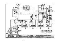
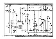
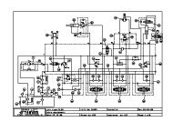
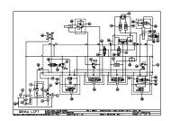
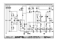
Main differences with the <strong>HA</strong><strong>32</strong><strong>PX</strong>- the Head module takes care of the drive pump command (SM4 and YV30 A&B),- the controllers are different as they are supplied in 4-20mA current , therefore the setpoint is different :4mA 12 mA 20 mAMini position Middle position Maxi position0 .63 VDC 1.9 VDC 3.16 VDC125 points* 380 points* 645 points** points read on Optimizer calibrator (by this , we can also check that the impedance from R100 to R104are not OK : in the contrary case , the values in points are shifted fwd)- the Head software has been modified , its not anymore possible to adjust with the Optimizer calibrator ,the setting parameters from turret movements ( they are fixed at 85% of setting parameters from cagemovements)- the emergency pump gives now 100% of flow for the movements before reaching the 130 bars ( avoidmotor overheating and save time in case of emergency descent)- An overload board takes care about the cage overload device (system controlled by angle transmittersA1 and A2 and pressure sensors on jib cylinder G1 and G2)As per <strong>HA</strong>260<strong>PX</strong>, this overload board is supplied in 12VDC( wire 242, terminal J4.1) , inside there is abooster in order to supply the pressure sensors in 16VDC and a transformer 5VDC for the transmitters A1and A2.The internal relays detect the overload (wires 213 and 214) :- 2 contacts closed : normal condition- 2 contacts opened : overload- 1 closed , 1 open ( ex bottom of cylinder) : so either lift cut ( contact closed) or descent is cut (contact open) depends which one .The overload calibration ( jib learning) is done on wire 607.On main boom , 3 high resistant connector which make the interconnection between upper and lowercontrol box ( 2 cables of 30x 1 mm2 and one for 220VAC option), it’s easier for boom dismantlingA system of angle and length transmitters manage the outreach limitation for both booms (SL3, SL4, SL7,SL8, SQ43, SQ44 and SQ45)The manual cage compensation is limited at +/- 10% and command by the signals coming from theoverload board U2.The input jib and cage compensation are relayed ( one toggle switch for both commands see diode D<strong>32</strong>and D34)The dispatch relay KA50 and KA51 manage the synchronisations between the booms.The proximity sensors ( SQ43 for main boom ) and SQ44 and SQ45 for primary booms detects the lengthof the booms thanks to the magnets fixed along the boom element.Buzzer is relayed ( SB5 and KM8)Training Dpt - 2006 4