Katalog 2009 pdf - ARNOLD - Ersatzteile
Katalog 2009 pdf - ARNOLD - Ersatzteile
Katalog 2009 pdf - ARNOLD - Ersatzteile
- No tags were found...

Create successful ePaper yourself
Turn your PDF publications into a flip-book with our unique Google optimized e-Paper software.
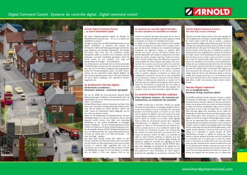
Digital Command Control . Systeme de contrôle digital . Digital command controlHornby Digital Command Control- so macht Modellbahn Spaß!Le système de contrôle digital Hornby...la vraie manière de contrôler un réseau!Hornby Digital Command Control...The real way to run a railway!Mit diesen Digitalsteuergeräten beginnt die Zukunft derModellbahnsteuerung genau jetzt – nie war es so einfach, eineModellbahn zu steuern!Die Tage, an denen man eine EDV-Ausbildung brauchte, um einedigitale Modellbahn zu bedienen, sind gezählt. DieFachsprache, irreführende Bedienungsanleitungen und die komplexeBedienung sind ebenfalls Vergangenheit. Das Hornby-DCC-System stellt sicher, dass die erhältlichen Hornby-Steuergeräte einfach zu verstehen und zu bedienen sind. AlleAnleitungen sind leicht verständlich geschrieben. Schritt fürSchritt werden Sie zum Lokführer Ihrer Züge undFahrdienstleiter Ihrer Anlage – es ist kinderleicht!Das Hornby-System unterscheidet sich von den konventionellen12-Volt-Fahrreglern insoweit, dass die Lokomotiven damit internstatt über die an den Gleisen anliegende Spannung gesteuertwerden. Die Hornby-Steuergeräte „Select“ und „Elite“ kommunizierenmit den Lokomotiven mittels digitaler Befehlen, dieüber die Gleise gesendet werden. Dazun muss jede Lokomotivemit einem kleinen Empfänger, dem sogenannten Decoder,ausgerüstet sein.So funktioniert Hornby DigitalKinderleicht zu bedienen…Minimaler Aufwand – maximaler Spielspaß!Der von der NMRA (die US-amerikanische National ModelRailroad Association) zertifizierte Lokomotivdecoder kann dieDigital-Befehle, die von der Zentrale aus gesendet werden, „verstehen“und verarbeiten.Auf diese Weise können mehrere Lokomotiven auf einem Gleisfahren, ohne dass dafür die Anlage aufwendig verkabelt werdenmuss. Mit der Tastatur der beiden Zentralen „Select“ und„Elite“ können die Lokomotiven einfach aufgerufen und wieeine echte Lok gesteuert werden.Stellen Sie sich beispielsweise ein Bahnbetriebswerk auf einerModellbahnanlage vor, in dem die Lokomotiven dicht an dichtabgestellt werden können, ohne dafür eine aufwendigeVerkabelung zu den großen Schaltbänken zu benötigen.Apropos Schaltbänke – mit dem Hornby-Digitalsystem könnennatürlich auch Weichen und andere Schaltartikel gesteuert werden.Ein spezieller Decoder (R 8247 für Weichenantriebe) kannbis zu vier Weichenantriebe oder andere Magnetartikel steuernund wird z.B. einfach ganz in der Nähe der Antriebe – z.B.unter der Anlage – platziert.Drei Kabel jedes Antriebs werden dann einfach mit demDecoder verbunden. Der Weichen-Decoder selbst wird einfachmit zwei Kabeln am Gleis angeschlossen. Dazu wird mit jedemDecoder ein einfacher Klipp mitgeliefert. Wie auch dieLokomotiven wird der Decoder somit über die Gleise mit Stromund Digitalbefehle versorgt. Um z.B. eine Weiche zu schalten,wird ein Befehl in Form einer digitalen Zahl von derL’avenir de contrôle de réseau ferroviaire est ici, avec lesystème numérique probablement le plus logique et simpleà manipuler de l’univers du modélisme ferroviaire!Le temps où un ordinateur était nécessaire afin d’utiliserun réseau en digital est à présent révolu. Le jargon technique,les instructions confuses et les contraintes techniquescomplexes ont également disparu. Le système DCCHornby vous assure que les contrôleurs Hornby dès àprésent disponibles sont simples à comprendre et se manipulentde manière presque instinctive. Toutes les instructionsmontrent chaque étape des différentes programmationspossibles. En suivant chacune des étapes, vous pourrezdonc faire circuler vos trains sans délai. C’est aussi simpleque ça! Le système Hornby diffère des systèmes 12volts conventionnels dans le sens où chaque locomotiveest contrôlée individuellement et en interne, contrairementau système classique où direction et vitesse sontconfigurées en ajustant la tension de la voie. Lorsqu’ellessont connectées au réseau, les unités de contrôle «Select»et «Elite» ne délivrent pas seulement un courant de 15volts alternatif, mais également des signaux d’information àtoutes les locomotives et accessoires qui sont reliés auréseau. Chaque locomotive DCC doit être équipée d’unrécepteur muni d’un micro-processeur appelé décodeur.Le système Digital Hornby expliquéC’est tellement naturel... Un minimum deconnections, un maximum de résultats!Le NMRA certifie que le décodeur Hornby est capabled’écouter les informations ou messages adressés à la locomotivedans laquelle se trouve le décodeur. De cette façonplusieurs locomotives peuvent se trouver sur une mêmevoie et peuvent se déplacer sans avoir besoin d’un quelconquecâblage compliqué ou de sections isolées. En utilisantle clavier se trouvant sur les deux unités digitalesSelect et Elite, les locomotives peuvent être «appelées»individuellement et déplacées comme dans la réalité.Imaginez un réseau où les locomotives sont placées prochesles unes des autres et où en utilisant le système digitalHornby les locomotives peuvent être manœuvréesd’un endroit à un autre sans avoir à se soucier de la connexionde plusieurs mètres de câble à un ensemble derelais et autres sections isolantes, en espérant que toutcela puisse fonctionner! The système digital Hornby estégalement capable de contrôler des aiguillages, de façontout à fait semblable. Un décodeur spécial (R 8247 décodeurpour aiguillages et accessoires) est capable de contrôlerquatre moteurs d’aiguillage ou accessoires et peutêtre positionné à votre convenance sur votre réseau àproximité des aiguillages ou accessoires concernés. TroisThe future of model railway control is here with arguably themost straightforward and simple to operate digital controllers inthe model railway world! The days of needing a computerdegree to operate a digital model railway have gone. The technicaljargon, the confusing instructions and the complex operatingrequirements have also gone. The Hornby DCC system ensuresthat the Hornby control units that are available are simple tounderstand and very straightforward to operate. All instructionsare “stage” written so that by following the step by step instructionsthe trains can be running in next to no time. It is as simpleas that! The Hornby system differs from the conventionaltype of 12V controllers in as much that it is the individual locomotivesthat are controlled internally rather than the controllingof a locomotive’s speed and direction by varying the current tothe track. The Hornby “Select” and Hornby “Elite” digital unitswhen connected to the track pass not only a constant 15V ACvoltage along the rails but also information signals to all locomotivesand accessories that are on or are connected to thetrack. Each locomotive that is DCC controlled must have internallyfitted a small micro processor based receiver called adecoder.Hornby Digital explainedIt’s so straightforward...Minimum wiring, maximum effect!The NMRA certificated Hornby locomotive decoder is capableof “listening” for information or messages which refer to thelocomotive that the decoder is fitted to. In this way several locomotivescan be placed on the same track and moved individuallywithout the need for complicated wiring or the use of isolatingsections of track. Using the keypad that is on both theSelect and Elite digital unit’s, locomotives can be “called up”individually and operated just like the real thing. Imagine, a busymodel railway layout where locomotives are positioned closetogether and where by using the Hornby digital system locomotivescan be manoeuvred from one place to another withoutworrying about the complexities of having to connect metres ofwiring to a bank of switches and isolating sections and hopingthat the whole thing will work! The Hornby digital system is alsocapable of point operation in much the same way as the controllingof a locomotive. A special decoder (R 8247Point/Accessory Decoder) is capable of working four pointmotors or solenoid operated accessories and can be positionedin a convenient part of a layout close to where the chosenpoints or accessories are situated. Three wires from each pointmotor are then connected to the relevant terminals of the unit.For the point/accessory decoder to function two wires are thenconnected to the input terminals of the decoder with the otherend of the wires being attached to the track via a power connectingclip supplied with the decoder and it is along these9www.hornbyinternational.com