CS® 3000/4000/4080 HZ - Peavey
CS® 3000/4000/4080 HZ - Peavey
CS® 3000/4000/4080 HZ - Peavey
- No tags were found...

You also want an ePaper? Increase the reach of your titles
YUMPU automatically turns print PDFs into web optimized ePapers that Google loves.
Intended to alert the user to the presence of uninsulated “dangerous voltage” within the product’s enclosure that may be of sufficientmagnitude to constitute a risk of electric shock to persons.Intended to alert the user of the presence of important operating and maintenance (servicing) instructions in the literature accompanyingthe product.CAUTION: Risk of electrical shock — DO NOT OPEN!CAUTION: To reduce the risk of electric shock, do not remove cover. No user serviceable parts inside. Refer servicing to qualified servicepersonnel.WARNING: To prevent electrical shock or fire hazard, this apparatus should not be exposed to rain or moisture‚ and objects filled withliquids‚ such as vases‚ should not be placed on this apparatus. Before using this apparatus‚ read the operating guide for further warnings.Este símbolo tiene el propósito, de alertar al usuario de la presencia de “(voltaje) peligroso” sin aislamiento dentro de la caja del productoy que puede tener una magnitud suficiente como para constituir riesgo de descarga eléctrica.Este símbolo tiene el propósito de alertar al usario de la presencia de instruccones importantes sobre la operación y mantenimiento en lainformación que viene con el producto.PRECAUCION: Riesgo de descarga eléctrica ¡NO ABRIR!PRECAUCION: Para disminuír el riesgo de descarga eléctrica, no abra la cubierta. No hay piezas útiles dentro. Deje todo mantenimientoen manos del personal técnico cualificado.ADVERTENCIA: Para prevenir choque electrico o riesgo de incendios, este aparato no se debe exponer a la lluvia o a la humedad. Losobjetos llenos de liquidos, como los floreros, no se deben colocar encima de este aparato. Antes de usar este aparato, lea la guia defuncionamiento para otras advertencias.Ce symbole est utilisé dans ce manuel pour indiquer à l’utilisateur la présence d’une tension dangereuse pouvant être d’amplitudesuffisante pour constituer un risque de choc électrique.Ce symbole est utilisé dans ce manuel pour indiquer à l’utilisateur qu’il ou qu’elle trouvera d’importantes instructions concernant l’utilisationet l’entretien de l’appareil dans le paragraphe signalé.ATTENTION: Risques de choc électrique — NE PAS OUVRIR!ATTENTION: Afin de réduire le risque de choc électrique, ne pas enlever le couvercle. Il ne se trouve à l’intérieur aucune pièce pouvantêtre reparée par l’utilisateur. Confiez I’entretien et la réparation de l’appareil à un réparateur <strong>Peavey</strong> agréé.AVIS: Dans le but de reduire les risques d’incendie ou de decharge electrique, cet appareil ne doit pas etre expose a la pluie ou a l’humiditeet aucun objet rempli de liquide, tel qu’un vase, ne doit etre pose sur celui-ci. Avant d’utiliser de cet appareil, lisez attentivement le guidefonctionnant pour avertissements supplémentaires.Dieses Symbol soll den Anwender vor unisolierten gefährlichen Spannungen innerhalb des Gehäuses warnen, die von AusreichenderStärke sind, um einen elektrischen Schlag verursachen zu können.Dieses Symbol soll den Benutzer auf wichtige Instruktionen in der Bedienungsanleitung aufmerksam machen, die Handhabung undWartung des Produkts betreffen.VORSICHT: Risiko — Elektrischer Schlag! Nicht öffnen!VORSICHT: Um das Risiko eines elektrischen Schlages zu vermeiden, nicht die Abdeckung enfernen. Es befinden sich keine Teile darin,die vom Anwender repariert werden könnten. Reparaturen nur von qualifiziertem Fachpersonal durchführen lassen.WARNUNG: Um elektrischen Schlag oder Brandgefahr zu verhindern, sollte dieser Apparat nicht Regen oder Feuchtigkeit ausgesetztwerden und Gegenstände mit Flüssigkeiten gefuellt, wie Vasen, nicht auf diesen Apparat gesetzt werden. Bevor dieser Apparat verwendetwird, lesen Sie bitte den Funktionsführer für weitere Warnungen.ENGLISH SPANISHFRENCH DEUTSCH人 体 への 電 気 ショックの 危 険 が 考 えられる 製 品 筐 体 内 の 非 絶 縁 「 危 険 電 圧 」の 存 在 をユーザーに 警 告 す るものです。製 品 に 付 属 している 説 明 書 に 記 載 の 重 要 な 操 作 およびメンテナンス(サービス) 要 領 の 存 在 をユーザーに 警 告 するものです。注 意 : 電 気 ショックの 危 険 あり — 開 けないでください!注 意 : 電 気 ショックの 危 険 を 低 減 するため、カバーを 外 さないでください。 内 部 部 品 はユーザーによるサービス 不 可 。 資 格 のあるサービス 要 因 のサービスを 要 請 してください。警 告 : 電 気 ショックまたは 火 災 の 危 険 を 避 けるため、この 装 置 を 雨 または 湿 気 にさらしてはなりません。ま た、 過 敏 など 液 体 を 含 む 物 をこの 装 置 上 に 置 いてはなりません。この 装 置 を 使 用 する 前 に、 警 告 事 項 につ いて 操 作 ガイドをお 読 みください。JAPANESE
ENGLISHCS ® <strong>3000</strong>/<strong>4000</strong>/<strong>4080</strong> <strong>HZ</strong>Power AmplifiersCongratulations on your purchase of a <strong>Peavey</strong> CS Series power amplifier! Designed for years of reliable operation, CS Seriesamplifiers offer the sonic superiority and unsurpassed reliability for which <strong>Peavey</strong> is famous in a rugged, compact unit.Advanced technologies and extensive protection circuitry allow operation with greater efficiency, even under difficult loadsand power conditions. The DDT (Distortion Detection Technique) circuit ensures trouble-free operation into loads as lowas 2 ohms (4 ohms for model CS <strong>4080</strong> <strong>HZ</strong>), protects speakers and ensures, protects drivers and ensures sonic integrity evenin extreme overload conditions. <strong>Peavey</strong>’s high-efficiency design uses tunnel-cooled heat sinks and dual-speed DC fans forconsistent lower overall operating temperature, resulting in longer output transistor life.<strong>Peavey</strong> CS Series amplifiers are simple to operate and housed in ultra-strong steel chassis, but improper use can bedangerous. Some CS Series amplifiers are very high powered and can put out high voltages and sizable currents at frequenciesup to 30 kHz. Always use safe operating techniques with these amplifiers.FOR YOUR SAFETY, READ THE IMPORTANT PRECAUTIONS SECTION, AS WELL AS INPUT, OUTPUT AND POWERCONNECTION SECTIONS.UnpackingUpon unpacking, inspect the amplifier. If you find any damage, notify your supplier immediately. Only the consignee(the supplier from whom you purchased the amplifier) may institute a claim with the carrier for damage incurredduring shipping. Be sure to save the carton and all packing materials. Should you ever need to ship the unit back to<strong>Peavey</strong> or one of its offices, service centers or the supplier, use only the original factory packing. If the shipping cartonis unavailable, contact <strong>Peavey</strong> to obtain a replacement.MountingCS Series amplifiers will mount in standard 19" racks. Rear mounting ears are also provided for additional support,which is recommended in non-permanent installations like mobile or touring sound systems. Because of the cablesand connectors on the rear panel, a right angle or offset screwdriver or hex key will make it easier to fasten the rearmounting ears to the rails.Cooling RequirementsCS Series amplifiers use a forced-air cooling system to maintain a low, consistent operating temperature. Air isdrawn into the amplifier by fans on the back panel and courses through the cooling fins of the tunnel-configuredchannel heat sinks, then exhausts through the front panel grilles. If either heat sink gets too hot, a sensing circuit willdisconnect the load for that particular channel. It is important to have an air inlet at the back of the amplifier to allowcooling air to enter. If the amp is rack mounted, do not use doors or covers on the back of the rack, as the intake airmust flow without resistance. Make sure that there is one (1) standard rack space opening for every three mountedpower amplifiers.
Wire Guage ChartsStranded Cable Lgth.(ft.)Wire Gauge (AWG)Power Loss(8 ohm load)Power Loss(4 ohm load)Power Loss(2 ohm load)518161412100.81%0.510.320.200.1281.61%1.020.640.400.253.2%2.01.280.800.511018161412101.61%1.020.640.400.253.2%2.01.280.800.516.2%4.02.51.601.0140181614121086.2%4.02.51.601.010.6011.9%7.75.03.22.01.2022%14.69.66.24.02.4801816141210811.9%7.75.03.22.01.2022%14.69.66.24.02.437%2617.811.87.74.7Stranded Cable Lgth.(m)Wire Gauge (mm 2 )Power Loss(8 ohm load)Power Loss(4 ohm load)Power Loss(2 ohm load)20.30.50.751.52.542.9%1.741.160.580.350.225.6%3.42.31.160.700.4410.8%6.74.52.31.390.8750.50.751.52.5464.3%2.91.450.870.550.378.2%5.62.91.741.090.7315.5%10.85.63.42.21.45100.50.751.52.5468.24%5.62.91.741.090.7315.5%10.85.62.91.741.0928%19.910.86.74.32.9300.751.52.5461015.5%8.25.13.22.21.3125%15.59.86.34.32.645%2818.212.08.25.1
Operation ModesStereo OperationFor stereo (dual channel) operation, turn the amplifier OFF and set the mode select switches on the back panel to theout (extended) position. In this mode, both channels operate independently of each other, with their input attenuatorscontrolling their respective levels. Thus, a signal at channel A’s input produces an amplified signal at channel A’soutput, while a signal at channel B’s input produces an amplified signal at channel B’s output.Parallel OperationFor parallel (dual-channel/single input) operation, turn the amplifier OFF and set the connector mode (CONN MODE)switch to the parallel position by depressing the switch. Both input connectors are then strapped together and driveboth channels with the same input signal. Because both connectors are strapped together, either connector can beused with a patch cable to drive the input of another amplifier. Output connections are the same as in Stereo mode.Both input attenuators remain active when in Parallel mode, allowing you to set different levels for each channel.Power and other general performance specifications are the same as in Stereo mode.Bridged Mono OperationBoth amplifier channels can be bridged together to make a very powerful single-channel monaural amplifier. Useextreme caution when operating in the bridged mode; potentially lethal voltage may be present at the outputterminals. To bridge the amplifier, depress the rear panel Bridge switch to the IN position. Direct the signal to channelA’s input and connect the speakers across the hot outputs (the “+” binding posts) of channels A and B. Only channelA’s input attenuator is active while in Bridge Mono mode. Both connectors are strapped together, so either connectorcan be used with a patch cable to drive the input of another amplifier.Unlike the stereo mode, in which one side of each output is at ground, both sides are hot in bridged mode. Channel A’sside is the same polarity as its input with the minimum nominal load impedance being 4 ohms (equivalent to drivingboth channels at 2 ohms) in bridged mode. Driving bridged loads of less than 4 ohms will activate the DDT circuitry(see Indicators section), resulting in a loss of power, and may also cause a thermal (overheating) overload.
CAUTION: The on/off switch in this unit does not break both sides of the primary mains.Hazardous energy can be present inside the chassis when the on/off switch is in the off position.11
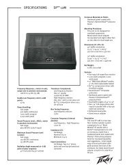
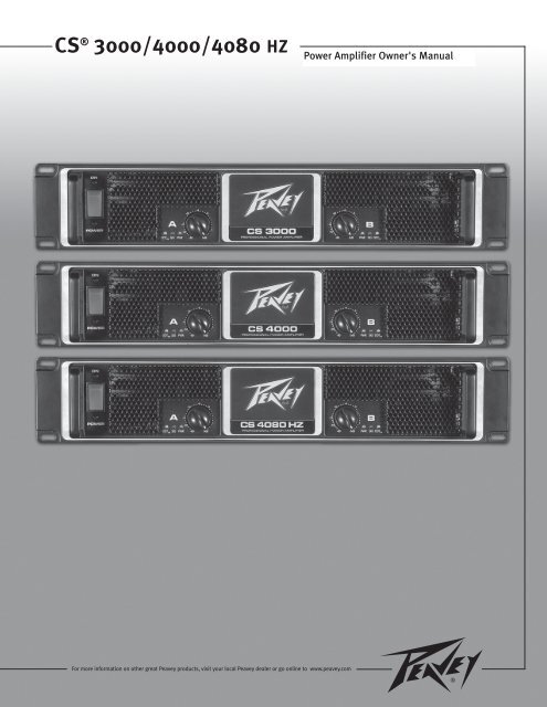
Front Panel3 1 1 32 2IndicatorsCS ® Series amplifiers feature three front panel LED indicators per channel: PWR (power), SIG (signal) and DDT (DistortionDetection Technique). These LED indicators inform the user of each channel’s operating status and warn of possible abnormalconditions.PWR LED (1)The Power LED indicates that the channel is operational. It illuminates under normal operation and remains on evenwhen the channel’s DDT circuit is activated.SIG LED (2)The Signal LED illuminates when its channel produces an output signal of greater than 1 volt RMS or 25 mV inputwith a 0 dB attenuation of the front panel knobs. This is useful in determining whether a signal is reaching and beingamplified by the amplifier. If the Signal LED is illuminated but no sound is present, that means a signal is present atthe amplifier but a problem may exist after the amplifier, such as in the cables or speakers.DDT LED (3)A channel’s DDT LED will illuminate at the onset of clipping. If the LEDs are flashing quickly and intermittently, thechannel is just at the clip threshold, while a steady, bright glow means the amp is clip limiting, or reducing gain toprevent severely clipped waveforms from reaching the speakers. See Distortion Detection Technique Limiting underthe Protection Features section for more information.
Protection FeaturesThe <strong>Peavey</strong> CS ® Series incorporates several circuits to protect the amplifier and speakers under virtually any situation. <strong>Peavey</strong>has made the amplifiers as foolproof as possible by making them immune to short and open circuits, mismatched loads,DC voltage and overheating. If a channel goes into the DDT gain reduction mode, the DDT LED illuminates. The clippingpercentage or output power is instantly reduced. When a problem occurs that causes a channel to go into a protection mode,the PWR (Power) LED for that channel will turn off. DC voltage on the output or excessive subsonic frequencies will cause thespeaker protection relay for that channel to open, protecting the speakers. If an amplifier channel overheats, the relay for thatchannel will open, disconnecting the load until the channel cools down, thus protecting the amplifier.Distortion Detection Technique LimitingAny time a channel is driven into hard, continuous clipping, the DDT circuit will automatically reduce the channel gainto a level just slightly into clipping, guarding the speakers against the damaging, high-power, continuous squarewaves that may be produced. Situations that may activate the DDT circuit include uncontrolled feedback, oscillations,an improper equipment setting or malfunction upstream from the amplifier. Normal program transients will not triggerDDT; only steady, excessive clipping will cause the DDT LED to illuminate.LFC Impedance SensingCS Series amplifiers feature innovative circuitry for safe operation into any load. When an amplifier senses a loadthat overstresses the output stage, the Load Fault Correction circuit adjusts the channel gain to a safe level. Extremeload fault under high power levels will cause the speaker relay to disconnect the load for the associated channel.This method of output stage protection is far more effective than the standard limiting found on conventional poweramplifiers. The LFC circuit is sonically transparent in normal use and unobtrusive when activated.Thermal ProtectionThe internal fans will keep the amplifier operating well within its intended temperature range under all normalconditions. If a channel’s heat sink temperature reaches 85°C (which may indicate an obstructed air supply), thatchannel will independently protect itself by opening the speaker relay to disconnect the load until it has cooled.During this time, the PWR LED will go out and the cooling fans will continue operating at high speed.Short CircuitIf an output is shorted, the LFC and thermal circuits will automatically protect the amplifier. The LFC circuit sensesthe short circuit as an extremely stressful load condition and attenuates the signal, protecting the channel’s outputtransistors from over-current stress. If the short circuit remains, the channel may eventually thermally protect itself byopening the speaker relay thereby disconnecting the load.DC Voltage ProtectionIf an amplifier channel detects DC voltage or subsonic frequencies at its output terminals, the speaker protection relayfor that channel will open, protecting the speakers.Turn-On/Turn-Off ProtectionUpon powering up, the amplifier mutes the input signals and stays in Protect mode with the speaker connect relaysopen for approximately four seconds. This allows the internal power supplies to charge and the amplifier to stabilize.After the relays engage, the signals slowly increase from muted to their normal level. Also, when power is removed,the input signals are muted so that no thumps or pops are heard.
Protection FeaturesRampUp Signal ControlWhenever a CS ® Series amplifier powers up or comes out of a protect mode, the RampUp circuit activates. While thespeakers are disconnected, the RampUp circuit fully attenuates the signal and activates the DDT LED. After theoutput relay closes, the signal slowly and gradually raises up to its set level. The PWR LED will illuminate and theDDT LED will turn off when the signal is no longer attenuated. The RampUp Signal Control circuit has some importantadvantages over the conventional instant-on circuits:1. If a signal is present during power-up (or when coming out of protect), the speakers are spared a sudden,potentially damaging burst of audio power.2. Because the gain is reduced until after the output relay closes, no arcing occurs at the contacts, therebyextending their useful life.Speaker ProtectionAll loudspeakers have electrical, thermal and physical limits that must be observed to prevent damage or failure. Excessivepower, low frequencies applied to high frequency drivers, severely clipped waveforms, and DC voltage can all be fatal to coneand compression drivers. <strong>Peavey</strong> CS Series amplifiers automatically protect speakers from DC voltages and subsonic signals.If using an electronic crossover, be extremely careful that the low and mid bands are connected to the correct amplifiers anddrivers and not to those designed for a higher frequency band. An amplifier’s clipping point is its maximum peak output power,and some of the higher powered <strong>Peavey</strong> CS Series amplifiers can deliver more power than many speakers can safely handle. Besure the peak power capability of the amplifier is not excessive for your speaker system. For more information, see the sectionon Protection Features.Fuses may also be used to limit power to speaker drivers, although as current-limiting rather than voltage-limiting devices, theyare an imperfect solution, and as the weakest links, they only limit once before needing replacement. Some poor-quality fuseshave a significant series resistance that could degrade the amplifier’s damping of the speaker’s motion and may even deterioratethe system’s sound quality. If you elect to use fuses, check with the speaker manufacturer to determine the proper currentrating and time lag required.Do not drive any low frequency speaker enclosure with frequencies lower than its own tuned frequency; the reduced acousticaldamping could cause a ported speaker to bottom out even at moderate power. Consult the speaker system specifications todetermine its frequency limits.
Amplifier Maintenance and User ResponsibilityA CS Series amplifier requires no routine maintenance and should not need internal adjustment during its lifetime. Your CSSeries amplifier is very powerful and can be potentially dangerous to loudspeakers and humans alike. It is your responsibilityto read the Important Precautions section and to make sure that the amplifier is installed, wired and operated properly asinstructed in this manual. Many loudspeakers can be easily damaged or destroyed by overpowering, especially with the highpower available from a bridged amplifier. Read the Speaker Protection section and always be aware of the speaker’s continuousand peak power capabilities.Service / Warranty InformationIn the unlikely event that your amplifier develops a problem, it must be returned to an authorized distributor, service center orshipped directly to our factory. To obtain service, contact your nearest <strong>Peavey</strong> Service Center, Distributor, Dealer, or any of theworldwide <strong>Peavey</strong> offices. For contact information, reach <strong>Peavey</strong> Inc. Customer Service directly:Telephone: 601-483-5365 (USA)Fax Number: 601-486-1278 (USA)For technical inquiries only, the <strong>Peavey</strong> Technical Services department can be faxed at 601-486-1361 (USA)Because of the complexity of the design and risk of electrical shock, all repairs must be performed only by qualified technicalpersonnel. If the unit needs to be shipped back to the factory, it must be sent in its original carton. It is the responsibility of theperson shipping the unit to properly package the amplifier. If you need a product shipping carton, please contact <strong>Peavey</strong> for areplacement.Please visit the <strong>Peavey</strong> website at: http://www.peavey.com.
Rated Power BridgedRated Power 2 x 2 ohmsRated Power 2 x 4 ohmsRated Power 2 x 8 ohmsCS ® Series <strong>3000</strong>/<strong>4000</strong>/<strong>4080</strong> <strong>HZ</strong>Power AmplifiersSPECIFICATIONSCS <strong>3000</strong> CS <strong>4000</strong> CS <strong>4080</strong> <strong>HZ</strong>3,050 watts @ 1 kHz at
CS ® Series SPECIFICATIONSCS <strong>3000</strong> CS <strong>4000</strong> CS <strong>4080</strong> <strong>HZ</strong>Slew Rate > 15V/us > 15V/us > 15V/usDamping Factor (8 ohms) > 500:1 @ 20 Hz - 1kHzPhase Response+5 to - 15 degrees from20 Hz to 20kHzInput Sensitivity 1.6 volts +/- 3% for 1kHz. 4 ohms rated power,1.37 volts +/- 3% for 1kHz. 2 ohms rated power> 500:1 @ 20 Hz - 1kHz+5 to - 12 degrees from20 Hz to 20kHz1.84 volts +/- 3% for 1kHz. 4 ohms rated power,1.58 volts +/- 3% for 1kHz. 2 ohms rated power> 500:1 @ 20 Hz - 1kHz+5 to - 12 degrees from20 Hz to 20kHz2.25 volts +/- 3% for 1kHz. 4 ohms rated powerInput Impedance 15 k ohms, balanced 15 k ohms, balanced 15 k ohms, balancedCurrent Draw @ 1/8 power 1,540 watts @ 2 ohms,1,000 watts @ 4 ohms,610 watts @ 8 ohmsCurrent Draw @ 1/3 power 3,650 watts @ 2 ohms,2,510 watts @ 4 ohms,1,535 watts @ 8 ohmsCoolingTwo back paneltemperature dependantvariable speed 80 mm DCfansControls2 front panel attenuators,rear panel Mode switchesIndicator LEDs 2 DDT (clip limiting), 2Signal presence, 2 ActivestatusProtectionThermal, DC, turn-onbursts, subsonic, incorrectloadsConnectorsCombi XLR & 6.3 mmphone input, Speakon ®and Binding Post speakeroutput, 15 amp IEC mainsconnectorConstruction16 ga. steel with cast frontpanel and cast handlesDimensions88.9mm x 482.6mm x376.3mm + 31.8mmfor rear support ears andconnectors (3.5”x19”x14.81” + 1.25”) + (1.5”)for handle depth1,825 watts @ 2 ohms,1,185 watts @ 4 ohms,720 watts @ 8 ohms4,535 watts @ 2 ohms,2,975 watts @ 4 ohms,1,835 watts @ 8 ohmsTwo back paneltemperature dependantvariable speed 80 mm DCfans2 front panel attenuators,rear panel Mode switches2 DDT (clip limiting), 2Signal presence, 2 ActivestatusThermal, DC, turn-onbursts, subsonic, incorrectloadsCombi XLR & 6.3 mmphone input, Speakon ®and Binding Post speakeroutput, 15 amp IEC mainsconnector14 ga. steel with cast frontpanel and cast handles88.9mm x 482.6mm x376.3mm + 31.8mmfor rear support ears andconnectors (3.5”x19”x4.81” + 1.25”) + (1.5”)for handle depth.1,185 watts @ 4 ohms,720 watts @ 8 ohms2,975 watts @ 4 ohms,1,835 watts @ 8 ohmsTwo back paneltemperature dependantvariable speed 80 mm DCfans2 front panel attenuators,rear panel Mode switches2 DDT (clip limiting), 2Signal presence, 2 ActivestatusThermal, DC, turn-onbursts, subsonic, incorrectloadsCombi XLR & 6.3 mmphone input, Speakon ®and Binding Post speakeroutput, 15 amp IEC mainsconnector16 ga. steel with cast frontpanel and cast handles88.9mm x 482.6mm x376.3mm + 31.8mmfor rear support ears andconnectors (3.5”x19”x14.81” + 1.25”) + (1.5”)for handle depth.Net Weight 18.05 kg (39.8 lbs.) 19.64 kg (43.3 lbs.) 21.45 kg (47.3 lbs.)Gross Weight 19.23 kg.(42.4 lbs.) 20.8 kg.(45.8 lbs.) 25.4 kg. (56 lbs.)All power measurements made at 120 VAC, power transformer cold. 4 ohm power is time limited by magnetic circuit breaker.
DEUTSCHCS ® <strong>3000</strong>/<strong>4000</strong>/<strong>4080</strong> <strong>HZ</strong>EndstufenHerzlichen Glückwunsch zum Kauf einer Endstufe der CS Series von <strong>Peavey</strong>! Die Verstärker der CS Series wurden füreinen zuverlässigen Betrieb und lange Lebensdauer entwickelt. In einem robusten, kompakten Gerät bieten sie dieüberragende Schallleistung und die unübertroffene Zuverlässigkeit, für die <strong>Peavey</strong> bekannt ist. Fortschrittliche Technologienund umfassende Schutzschaltungen ermöglichen einen effizienteren Betrieb auch bei problematischen Lasten undEnergiebedingungen. Die DDT-Schaltung (Distortion Detection Technique) gewährleistet einen störungsfreien Betrieb auchbei niedrigen Lasten bis zu 2 Ohm (4 Ohm beim Modell CS 4808 <strong>HZ</strong>), schützt Lautsprecher und Treiber und gewährleistetungestörte Schallleistung selbst unter extremer Überlastung. Die hochleistungsfähigen <strong>Peavey</strong>-Produkte sind mittunnelgekühlten Kühlkörpern und Gleichstromlüftern mit zweistufiger Drehzahl für kontinuierlich niedrigere allgemeineBetriebstemperatur ausgestattet, was die Lebensdauer des Endstufen-Transistors verlängert.Obwohl die Verstärker der <strong>Peavey</strong> CS Series relativ einfach zu bedienen und in ultrastarken Stahlgehäusen untergebracht sind,birgt ihr unsachgemäßer Einsatz Gefahren. Einige Verstärker der CS Series sind Hochleistungsverstärker, die hohe Spannungenund Ströme mit Frequenzen bis zu 30 kHz abgeben können. Achten Sie beim Einsatz dieser Verstärker immer auf sichereBetriebsverfahren.LESEN SIE SICH BITTE DIE ABSCHNITTE ÜBER WICHTIGE SICHERHEITSHINWEISE SOWIE ÜBER EINGANG, AUSGANGUND STROMANSCHLUSS DURCH, UM IHRE SICHERHEIT ZU GEWÄHRLEISTEN.AuspackenUntersuchen Sie den Verstärker beim Auspacken. Sollten Sie Beschädigungen feststellen, informieren Sie unverzüglichIhren Händler. Nur der Empfänger (der Händler, bei dem Sie das Gerät gekauft haben) kann gegenüber demSpediteur einen Anspruch aufgrund von Transportschäden geltend machen. Heben Sie den Karton und sämtlichesVerpackungsmaterial bitte auf. Sollte es irgendwann einmal erforderlich sein, das Gerät zu <strong>Peavey</strong> oder zu einemunserer Büros, Kundendienstzentren oder Händler zurückzuschicken, verwenden Sie dazu bitte ausschließlich dieOriginal-Werksverpackung. Sollte keine Versandverpackung mehr vorhanden sein, bitten Sie <strong>Peavey</strong> um Ersatz.MontageDie Verstärker der CS Series werden in genormten 19”-Racks montiert. Zur zusätzlichen Verstärkung sindMontageösen auf der Rückseite angebracht; dies wird für vorübergehende Installationen wie etwa mobile oder Tour-Beschallungssysteme empfohlen. Aufgrund der Kabel und Anschlüsse auf der Rückseite wird die Befestigung derhinteren Montageösen an den Schienen durch einen rechtwinkligen Schraubendreher, einen Winkelschraubendreheroder einen Sechskantschlüssel erleichtert.KühlanforderungenDie Verstärker der CS Series arbeiten mit einem Fremdkühlsystem, das eine niedrige gleichmäßige Betriebstemperaturgewährleistet. Luft wird durch Lüfter auf der Rückseite in den Verstärker eingesaugt, läuft durch die Kühlrippender tunnelartigen Kanalkühlkörper und wird durch das Gitter an der Vorderseite wieder abgegeben. Wird einer derKühlkörper zu heiß, trennt seine Sensorschaltung die Last von diesem jeweiligen Kanal ab. An der Rückseite desVerstärkers muss ein Lufteinlass zum Einsaugen der Kühlluft gelassen werden. Wird der Verstärker im Rack montiert,darf das Rack hinten nicht mit Türen oder Abdeckungen verschlossen werden. Die Zuluft muss unbehindert strömenkönnen. Zudem muss sichergestellt werden, dass eine (1) Standard-Rack-Höhe für jeweils drei montierte Endstufenoffen bleibt.
Vorsicht: Dieses Gerät kann gefährliche elektrische Stromspannungen unter gewissen Betriegsbedingungen an den Lautsprecher Ausgängen produdzieren. Bitte vermeiden Sie den direktenKontakt mit den Anschlüssen, Lausprecheranschlüssen und den Lautsprecherverkabelungen umVerletzungen durch gefährliche elektrische Stromspannungen zu vermeiden.
KabelstärkentabellenStranded Cable Lgth.(ft.)Wire Gauge (AWG)Power Loss(8 ohm load)Power Loss(4 ohm load)Power Loss(2 ohm load)518161412100.81%0.510.320.200.1281.61%1.020.640.400.253.2%2.01.280.800.511018161412101.61%1.020.640.400.253.2%2.01.280.800.516.2%4.02.51.601.0140181614121086.2%4.02.51.601.010.6011.9%7.75.03.22.01.2022%14.69.66.24.02.4801816141210811.9%7.75.03.22.01.2022%14.69.66.24.02.437%2617.811.87.74.7Stranded Cable Lgth.(m)Wire Gauge (mm 2 )Power Loss(8 ohm load)Power Loss(4 ohm load)Power Loss(2 ohm load)20.30.50.751.52.542.9%1.741.160.580.350.225.6%3.42.31.160.700.4410.8%6.74.52.31.390.8750.50.751.52.5464.3%2.91.450.870.550.378.2%5.62.91.741.090.7315.5%10.85.63.42.21.45100.50.751.52.5468.24%5.62.91.741.090.7315.5%10.85.62.91.741.0928%19.910.86.74.32.9300.751.52.5461015.5%8.25.13.22.21.3125%15.59.86.34.32.645%2818.212.08.25.1
BETRIEBSMODIStereobetriebFür den Stereobetrieb (mit zwei Kanälen) schalten Sie den Verstärker aus und stellen die Moduswahlschalter aufder Rückseite auf die ausgerastete (herausgezogene) Position. In diesem Modus arbeiten beide Kanäle unabhängigvoneinander, wobei ihre jeweiligen Pegel über die Eingangsdämpfer geregelt werden. Ein Signal am Eingang vonKanal A erzeugt somit ein verstärktes Signal am Ausgang von Kanal A, während ein Signal am Eingang von Kanal B einverstärktes Signal am Ausgang von Kanal B erzeugt.ParallelbetriebFür den Parallelbetrieb (zwei Kanäle/ein Eingang) schalten Sie den Verstärker aus und stellen denAnschlussmodusschalter (CONN. MODE) auf die Parallelposition, indem Sie ihn eindrücken. Beide Eingangsbuchsenwerden dadurch miteinander verknüpft und treiben beide Kanäle mit demselben Eingangssignal. Da beide Buchsenmiteinander verknüpft sind, kann jede Buchse mit einem Verbindungskabel verwendet werden, um den Eingangeines weiteren Verstärkers zu betreiben. Die Ausgangsanschlüsse sind dieselben wie im Stereomodus. BeideEingangsdämpfer bleiben im Parallelmodus aktiviert, sodass Sie verschiedene Pegel für jeden Kanal einstellenkönnen. Stromwerte und andere allgemeine Leistungsdaten sind dieselben wie im Stereomodus.Bridged-Mono-BetriebBeide Verstärkerkanäle können gebrückt werden, um einen äußerst leistungsfähigen Mono-Verstärker mit einem Kanaleinzurichten. Gehen Sie beim Betrieb im Bridged-Modus mit äußerster Vorsicht vor, da an den Ausgangsklemmenmöglicherweise tödliche Spannung vorliegen kann. Zum Brücken des Verstärkers drücken Sie den Bridge-Schalterauf der Rückseite in die Position IN. Schließen Sie das Signal an den Eingang von Kanal A an, und schließen Siedie Lautsprecher über die spannungsführenden Ausgänge (die „+“-Anschlussklemmen) der Kanäle A und B an. ImBridged-Mono-Betrieb ist nur der Eingangsdämpfer von Kanal A aktiv. Da beide Buchsen miteinander verknüpft sind,kann jede Buchse mit einem Verbindungskabel verwendet werden, um den Eingang eines weiteren Verstärkers zutreiben.Anders als beim Stereo-Modus, bei dem eine Seite jedes Ausgangs geerdet ist, sind im Bridged-Modus beide Seitenspannungsführend. Die Seite von Kanal A hat dieselbe Polarität wie sein Eingang, wobei die Mindestnennlastimpedanzim Bridged-Modus 4 Ohm beträgt (was dem Betrieb beider Kanäle bei 2 Ohm entspricht). Durch das Treibengebrückter Lasten von unter 4 Ohm wird die DDT-Schaltung aktiviert (siehe Abschnitt Anzeigen), was zu einemLeistungsverlust führt und eine Wärmeüberlastung (Überhitzung) zur Folge haben kann.
Vorsicht: Der Ein/Aus-Schalter dieses Gerätes unterbricht nicht beide Seiten der primärenHauptstromleitung. Gerfährliche elektrische Stromspannungen können immer noch innerhalb des Gehäuses vorhanden sein, auch wenn der Ein/Aus-Schalter in der Ausschaltstellung ist. 2222
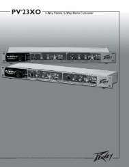
VORDERSEITE3 1 1 32 2ANZEIGENDie Verstärker der CS ® Series sind mit drei LED-Anzeigen pro Kanal auf der Vorderseite ausgestattet: PWR (Power), SIG(Signal) und DDT (Distortion Detection Technique). Die LED-Anzeigen informieren den Anwender über den Betriebsstatus desjeweiligen Kanals und warnen vor möglichen Störungen.PWR-LED (1)Die Power-LED zeigt an, dass das Gerät in Betrieb ist. Sie leuchtet beim Normalbetrieb sowie auch bei aktivierter DDT-Schaltung des Kanals auf.SIG-LED (2)Die Signal-LED leuchtet auf, wenn der zugehörige Kanal bei einer Dämpfung der Knöpfe auf der Vorderseite von 0 dBein Ausgangssignal von über 1 V RMS oder 25 mV erzeugt. Hiermit lässt sich einfacher ermitteln, ob ein Signal denVerstärker erreicht und von ihm verstärkt wird. Leuchtet die Signal-LED, ohne dass etwas zu hören ist, liegt zwar einSignal am Verstärker vor, aber hinter dem Verstärker, z.B. in den Kabeln oder Lautsprechern, besteht eine Störung.DDT-LED (3)Die DDT-LED eines Kanals leuchtet beim Einsetzen von Clipping auf. Blinken die LEDs rasch und intermittierend,befindet sich der Kanal an der Schwelle zum Clipping. Leuchten sie kontinuierlich und hell auf, grenzt der Verstärkerdas Clipping ein oder verringert die Verstärkung um zu verhindern, dass stark gekappte Wellenformen dieLautsprecher erreichen. Weitere Informationen dazu finden Sie unter Schutz durch Distortion Detection Technique imAbschnitt Schutzfunktionen.
SCHUTZFUNKTIONENRampUp-SignalregelungWird ein Verstärker der CS ® Series eingeschaltet oder ein Schutzmodus ausgeschaltet, wird die RampUp-Schaltungaktiviert. Solange die Lautsprecher abgetrennt sind, dämpft die RampUp-Schaltung das Signal vollständig undaktiviert die DDT-LED. Nachdem sich das Ausgangsrelais geschlossen hat, steigt das Signal langsam und allmählichauf seinen eingestellten Pegel an. Die PWR-LED leuchtet auf und die DDT-LED erlischt, wenn das Signal nicht mehrgedämpft wird. Die RampUp-Signalregelung hat gegenüber den herkömmlichen Momenteinschaltungen einigewichtige Vorteile:1. Ist während des Einschaltens (oder bei Ausschalten eines Schutzmodus) ein Signal vorhanden, werden dieLautsprecher vor einem plötzlichen, möglicherweise schädigenden Audiosignalbündel geschützt.2. Da die Verstärkung verringert wird, bis das Ausgangsrelais geschlossen ist, gibt es an den Kontakten keineFunkenbildung, was ihre Lebensdauer verlängert.LAUTSPRECHERSCHUTZSämtliche Lautsprecher verfügen über elektrische, thermische und physikalische Grenzwerte, die eingehalten werden müssen,um Schäden oder Versagen zu verhindern. Übermäßige Leistung, Niederfrequenzen an Hochfrequenztreibern, stark gekappteWellenformen und Gleichspannung können für Kegel und Kompressionstreiber das Ende bedeuten. Die Verstärker der <strong>Peavey</strong>CS Series schützen die Lautsprecher automatisch vor Gleichspannungen und Unterschallsignalen. Bei Verwendung einerelektronischen Frequenzweiche muss unbedingt darauf geachtet werden, dass die niedrigen und mittleren Bänder an diekorrekten Verstärker und Treiber und nicht an die für ein Band mit höherer Frequenz angeschlossen werden. Der Clipping-Punkteines Verstärkers ist seine maximale Spitzenausgangsleistung, und einige der <strong>Peavey</strong>-Hochleistungsverstärker der CS Serieskönnen eine höhere Leistung bringen, als viele Lautsprecher ohne Schäden bearbeiten können. Achten Sie darauf, dass dasSpitzenleistungsvermögen des Verstärkers Ihr Lautsprechersystem nicht überlastet. Weitere Informationen hierzu finden Sie imAbschnitt Schutzfunktionen.Sicherungen können ebenfalls verwendet werden, um die Leistungszufuhr zu den Lautsprechertreibern zu begrenzen. Als eherstrombegrenzende anstatt spannungsbegrenzende Vorrichtungen sind sie jedoch eine unzureichende Lösung, und als schwächstesGlied können sie nur einmal eingesetzt werden und müssen dann ausgetauscht werden. Einige Sicherungen schlechterQualität verfügen über einen beträchtlichen Reihenwiderstand, der die Dämpfung der Lautsprecherbewegung durch denVerstärker beeinträchtigen und sogar die Klangqualität des Systems verschlechtern kann. Sollten Sie Sicherungen einsetzenwollen, erfragen Sie bitte beim Lautsprecherhersteller die geeigneten Stromnennwerte und die erforderliche Trägheit.Treiben Sie eine niederfrequente Lautsprecherbox nie mit Frequenzen, die unter ihrer jeweiligen abgestimmten Frequenz liegen.Aufgrund der verringerten Schalldämpfung könnte eine auf eine bestimmte Resonanz abgestimmte Box selbst bei mäßiger Leistungvöllig absacken. Die Frequenzgrenzen eines Lautsprechersystems finden Sie unter den jeweiligen technischen Daten.
WARTUNG DES VERSTÄRKERS UND VERANTWORTUNG DES NUTZERSEine regelmäßige Wartung der Verstärker der CS Series ist nicht erforderlich, und eine interne Justierung sollte während ihrergesamten Lebensdauer überflüssig sein. Ihr Verstärker der CS Series ist äußerst leistungsfähig und kann sowohl für Lautsprecherals auch für Personen Gefahren bergen. Lesen Sie sich als verantwortlicher Nutzer den Abschnitt Wichtige Sicherheitshinweisedurch, und achten Sie darauf, dass Installation, Anschluss und Betrieb des Verstärkers korrekt gemäß den Anweisungenin dieser Anleitung erfolgen. Viele Lautsprecher werden durch übermäßige Verstärkerleistung beschädigt oder zerstört, wasinsbesondere bei den gebrückten Hochleistungsverstärkern der Fall ist. Lesen Sie sich den Abschnitt Lautsprecherschutz durch,und beachten Sie immer Dauer- und Spitzenleistungsvermögen des Lautsprechers.KUNDENDIENST - INFORMATIONEN ZUR GARANTIESollte bei Ihrem Verstärker tatsächlich einmal ein Problem auftreten, muss er zu einem autorisierten Vertrieb, Kundendienstzentrumoder direkt in unser Werk geschickt werden. Für Kundendienstleistungen wenden Sie sich bitte an das nächste <strong>Peavey</strong>-Kundendienstzentrum, den nächsten Vertrieb oder Händler oder eines der weltweiten <strong>Peavey</strong>-Büros. Adressen usw. erfahren Siedirekt beim <strong>Peavey</strong> Inc. Customer Service:Telefon: 601-483-5365 (USA)Fax: 601-486-1278 (USA)Für ausschließlich technische Fragen können Sie ein Fax an die Abteilung <strong>Peavey</strong> Technical Services senden:601-486-1361 (USA).Aufgrund der komplexen Konstruktion und der Gefahr eines elektrischen Schlags müssen alle Reparaturen ausschließlichvon qualifizierten Technikern ausgeführt werden. Falls das Gerät ins Werk eingeschickt werden soll, muss es in derOriginalverpackung verschickt werden. Die Person, die das Gerät verschickt, ist für die sachgemäße Verpackung desVerstärkers verantwortlich. Sollten Sie eine neue Versandverpackung benötigen, bitten Sie <strong>Peavey</strong> um Ersatz.Bitte besuchen Sie die Webseite von <strong>Peavey</strong> unter: http://www.peavey.com.
CS ® Series TECHNISCHE DATENCS <strong>3000</strong> CS <strong>4000</strong> CS <strong>4080</strong> <strong>HZ</strong>Anstiegsgeschwindigkeit >15V/us >15V/us >15V/usDämpfungsfaktor (8 Ohm) >500:1 bei 20 Hz -1 kHz >500:1 bei 20 Hz -1 kHz >500:1 bei 20 Hz -1 kHzPhasenfrequenzgang +5 bis -15 Grad von 20Hz-20 kHzEingangsempfindlichkeit 1,6 Volt +/- 3% für 1kHz. 4 Ohm Nennleistung,1,37 Volt +/- 3% für 1kHz. 2 Ohm Nennleistung+5 bis -12 Grad von 20Hz-20 kHz1,84 Volt +/- 3% für 1kHz. 4 Ohm Nennleistung,1,58 Volt +/- 3% für 1kHz. 2 Ohm Nennleistung+5 bis -12 Grad von 20Hz-20 kHz2,25 Volt +/- 3% für 1kHz. 4 Ohm NennleistungEingangsimpedanz 15 kOhm, symmetriert. 15 kOhm, symmetriert. 15 kOhm, symmetriert.Stromaufnahme bei 1/8LeistungStromaufnahme bei 1/3LeistungKühlungReglerLED-AnzeigenSchutzfunktionen1.540 Watt an 2 Ohm,1.000 Watt an 4 Ohm,610 Watt an 8 Ohm3.650 Watt an 2 Ohm,2.510 Watt an 4 Ohm,1.535 Watt an 8 OhmZwei temperaturabhängigeGleichstromlüfter mitvariabler Drehzahl,80 mm, auf der Rückseite2 Dämpfer vorne,Moduswahlschalter hinten2 DDT (Clipping-Begrenzung), 2Signalpräsenz, 2BetriebsstatusÜberhitzung, Gleichstrom,Einschaltspitzen,Unterschall, FehllastAnschlüsse Kombi-XLR- und ,3-mm-Kopfhörereingangs-, Speakon ® - undAnschlussklemmen-Lautsprecherausgangs-,IEC-Netzbuchsenr (15 A)1.825 Watt an 2 Ohm,1.185 Watt an 4 Ohm,720 Watt an 8 Ohm4.535 Watt an 2 Ohm,2.975 Watt an 4 Ohm,1.835 Watt an 8 OhmZwei temperaturabhängigeGleichstromlüfter mitvariabler Drehzahl,80 mm, auf der Rückseite2 Dämpfer vorne,Moduswahlschalter hinten2 DDT (Clipping-Begrenzung), 2Signalpräsenz, 2BetriebsstatusÜberhitzung, Gleichstrom,Einschaltspitzen,Unterschall, FehllastKombi-XLR- und ,3-mm-Kopfhörereingangs-, Speakon ® - undAnschlussklemmen-Lautsprecherausgangs-,IEC-Netzbuchsen (15 A)1.185 Watt an 2 Ohm,720 Watt an 4 Ohm2.975 Watt an 4 Ohm,1.835 Watt an 8 OhmZwei temperaturabhängigeGleichstromlüfter mitvariabler Drehzahl,80 mm, auf der Rückseite2 Dämpfer vorne,Moduswahlschalter hinten2 DDT (Clipping-Begrenzung), 2Signalpräsenz, 2BetriebsstatusÜberhitzung, Gleichstrom,Einschaltspitzen,Unterschall, FehllastKombi-XLR- und ,3-mm-Kopfhörereingangs-, Speakon ® - undAnschlussklemmen-Lautsprecherausgangs-,IEC-Netzbuchsen (15 A)BauweiseAbmessungenStahl (Stärke 16), mitGussfront und Gussgriffen88,9 mm x 482,6 mm x376,3 mm; 31,8 mm fürMontageösen und Steckerhinten sowie 38,1 mm fürHandgriffStahl (Stärke 14), mitGussfront und Gussgriffen88,9 mm x 482,6 mm x376,3 mm; 31,8 mm fürMontageösen und Steckerhinten sowie 38,1 mm fürHandgriffNettogewicht 18,05 kg 19,64 kg 19,64 kgBruttogewicht 19,23 kg 20,8 kg 20,8 kgStahl (Stärke 16), mitGussfront und Gussgriffen88,9 mm x 482,6 mm x376,3 mm: 31,8 mm fürMontageösen und Steckerhinten sowie 38,1 mm fürHandgriffAlle Messungen erfolgten bei 120 VAC mit kaltem Leistungstrafo. 4 Ohm Leistung zeitbegrenzt durch Magnetschutzschalter.
FRANÇAISCS ® <strong>3000</strong>/<strong>4000</strong>/<strong>4080</strong> <strong>HZ</strong>Amplificateurs de PuissanceFélicitations d’avoir choisi un amplificateur de puissance <strong>Peavey</strong> de la série CS. Ces unités sont concues pour vous permettreune utilisation intensive sans problèmes de fiabilité ou d’utilisation. Le tout dans une unité compacte, ils proposent unecircuiterie de pointe et des systèmes de protection qui ont fait la renommée de <strong>Peavey</strong>. L’un d’entre eux, le DDT (DistortionDetection) , est un circuit qui permet d’optimiser les performances de l’amplificateur sous grande charge en analysant le signalet le maintenant dans la zone de travail de votre amplificateur. Le système de ventilation breveté des amplificateurs CS, unecombinaison de ventilateur à vitesse variable et de radiateurs ‘à tunnels’ vous permettent de garder une efficacité maximummême après plusieurs heures d’utilisation.Bien que ces unités soient d’une très grande facilité d’utilisation et sont protégés par un chassis d’acier robuste, il vous fautquand même respecter des règles simples pour en tirer le meilleur parti. Certains d’entre eux peuvent générer de grandespuissances et donc travaille sur des signaux à haut voltage.POUR VOTRE PROPRE SECURITE ET CELLE DE VOTRE MATERIEL, LISEZ ATTENTIVEMENT CE MANUEL.DéballageInspecter votre unité lors du déballage. Au moindre problème, notifiez-le à votre revendeur immédiatement. Assurezvousde garder les emballages de votre unité, ils vous seront nécessaires si jamais vous devez envoyer votre unité à uncentre technique ou distributeur.InstallationVotre unité est concue pour de nombreuses applications, aussi bien en installation (système à demeure, homestudio,...) qu’en système mobile. Elle est au format rack 19” standard et est équipée d’oreilles de fixationssupplémentaires sur l’arrière.RefroidissementLes amplificateurs CS ® <strong>3000</strong> , <strong>4000</strong> et <strong>4080</strong> <strong>HZ</strong> utilisent un système de refroidissement à air forcé pour maintenirune parfaite température de fonctionnement. L’air est aspiré par les ventilateurs du panneau arrière, passent le longdes radiateurs en formes de tunels (pour le meilleur échange thermique possible) et sont expulsés par le panneauavant. Si le radiateur atteint des températures élevées, une protection déconnectera la charge du côté concerné. Il estprimordial d’avoir un excellent système de refroidissement. Si vous utilisez vos unités en Rack, ne jamais les fairefonctionner avec le couvercle avant fermé. De même, si vous l’arrière du rack est fermé, prévoyez au moins un espacelibre tous les 3 amplificateurs de puissance.
ATTENTION: Cet amplificateur peut produire sous certaines conditions d’utilisation un courant électrique dangereux en sortie de haut-parleur. Les sorties de haut-parleur doivent être protégées pour empêcher tout contact direct et la plus grande prudence est demandée pour éviter toutcontact accidentel avec l’énergie dangereuse présente sur les connexions de haut-parleur, lesterminaux et le câblage.
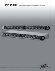
Panneau Avant3 1 1 32 2IndicateursLes unités de la série CS ® sont munies de trois Leds d’indication par canal: PWR (power), SIG (signal), et DDT (DistortionDetection Technique). Ces Leds vous informent de l’état de fonctionnement du canal et vous previennent d’éventuelsproblèmes.PWR LED (1)Cette Led vous indique que le canal est en état de fonctionnement.SIG LED (2)Cette Led située en bas de l’afficheur s’illumine si votre unité produit un signal de plus de 1 Volts RMS ou recoit 25mVen entrée avec l’atténuateur du panneau avant à 0dB. C’est utile pour vous confirmer la présence d’un signal à l’entréede votre amplificateur.DDT LED (3)Ces indicateurs s’illuminent lorsque la compression DDT travaille sur le signal. Cette illumination doit resterintermittente pour éviter une déformation audible du signal. Si elle s’illumine constamment, vous devez diminuez legain du signal amplifié. Reportez-vous à la Systèmes de Protection pour plus de détail.
Systèmes de ProtectionLes unités de la série CS ® incorporent de nombreux systèmes de protection pour tout problème à eux-même ou aux enceintes.<strong>Peavey</strong> a essayé de rendre l’appareil fiable, quelque soient les manipulations effectuées. Circuits de sortie ouvert, courantcontinu, mauvaise charge d’enceintes, surchauffe,… sont toutes des conditions pour lesquelles votre unité est équipéeen protection. Si un canal est soumis à une distortion, le système DDT réduira correspondamment le gain de ce canal,gardant le système fonctionnel, mais limitant la puissance disponible pour protéger les haut-parleurs. Quand un problèmefait qu’un canal se met en protection, la Led PWR s’éteindra. Courant continu en sortie, fréquences sub-graves excessivesou températures de fonctionnement anormale font que le relai de sortie du canal correspondant coupera le signal en sortie,jusqu’à résolution de la cause du problème.Limite de Détection de Distortion (DDT)Dès qu’un canal est poussé trop fort, la DDT réduira le gain du signal pour le maintenir en deca du seuil de coupure(clipping), protégeant vos enceintes de trop hauts voltages. La DDT s’activera pour les situations suivantes : effetde Larsen important, mauvais réglages (gain trop haut) ou un problème en amont de l’amplification de puissance.Un signal normal ne devrait pas engager la DDT. Seul un dépassement excessif de la limite des capacités de l’unité ladéclenchera.Test de Charge LFCLes unités CS sont équipées d’un nouveau circuit de protection qui permet aux amplificateurs de fonctionner quelquesoit l’impédance de la charge d’enceinte, en limitant le gain correspondamment. Ce système est beaucoup plusperformant que les systèmes purement limitatifs. Il est transparent sur le signal et donc inaudible.Protection ThermiqueLes ventilateurs internes de votre unité sont prévus pour garder les radiateurs dans les limites de fonctionnement del’amplificateur. Si l’un deux atteint 85°C, ce qui résulte certainement d’une obstruction du conduit de ventilation, lecanal correspondant se déconnectera de la charge de sortie jusqu’à atteindre une température accesptable. Durantcette période, la Led PWR du canal s’éteindra, la Led DDT s’illuminera et les ventilateurs tourneront à leur vitessemaximale.Court-CircuitSi une sortie est mise en court-circuit (problème d’enceinte!), le LFC et la protection thermique s’engageront. Le LFCdétectera tout d’abord le problème et le traitera comme uneimpédance très faible (réduction drastique du gain). Si leproblè§me persiste, la protection thermique disconnectera les sorties du canal correspondant.Courant ContinuSi un courant continu est détecté sur un canal, le relai de sortie disconnectera les sorties correspondantes pour éviterd’endommager les enceintes. La Led DC s’illumine pour indiquer cette situation.Protection de Mise Sous/Hors TensionA l’allumage, votre unité se mettra toujours en mode de protection, avec les sorties déconnectées pour a peu près 4secondes (temps de stabilisation des composants). Le gain du signal est graduellemnt augmenté jusqu’à la valeur ducontrôle du canal correspondant. En cas de mise hors tension, les sorties se disconnectent immédiatement pour évitertout bruit parasite dans les enceintes.
Systèmes de ProtectionSystème RampUp (contrôle de montée en puissance)Dès que votre unité est mise sous tension ou après qu’une protection se désengage, le circuit RampUp estactivé. Le gain du signal est graduellemnt augmenté jusqu’à la valeur du contrôle du canal correspondant. Cesystème présente le majeur avantage d’éviter les soudaines montées en puissance:1 – si un signal est deja présent à la mise sous tension2 – en évitant toute décharge résiduelle, et prolongeant ainsi la durée de vie de votre système d’enceintesProtection des Haut-ParleursTous les haut-parleurs ont des limites de fonctionnement, thermiques et physiques qu’il faut respecter. Trop de puissance,signal non-étudié pour le dit haut-parleur (non respect des fréquences admissibles), ondes limitées (clip) causant un effetd’écrètage et courant continu peuvent leur cuser des dommages irrémédiables. Les unités CS protègent automatiquement lesenceintes d’un courant continu ou d’une sub-fréquence trop prononcée. Les enceintes médium et aigues, particulièrement lesmoteurs de compression sont très sensibles aux surpuissance occasionnelles, ou aux fréquences trop graves, qui peuvent lesendommager très facilement. Prétez une attention toute particulière aux connections quand vous travaillez sur ces matériels.Assurez vous que la capacité de puissance (puissance peak) de votre amplificateur ne dépasse pas la puissance admissible devos composants.Un système de fusible peut être utilisé pour limiter la puissance délivrée à une enceinte. Ils ne représentent pas la solutionidéale car ils sont à remplacer après chaque dépassement, et contrôle plus l’intensité que le voltage d’un signal. De nombreuxfusibles ont de plus des valeurs de résistance non négligeables et risquent donc de détériorer le signal de part l’énergie perdue(qui ne sera certainement pas uniforme sur les fréquences). Si vous optez pour un système de protection d’enceintes à fusibles,consultez le fabricant des enceintes pour connaitre les meilleures valeurs de fusible (temps de réponse,…) à utiliser.N’envoyez pas de signal de fréquences plus graves que ce que l’enceinte réceptrice peut recevoir. Vous pourriez endommagervotre haut-parleur même à moyenne puissance. Consultez les caractéristiques de vos enceintes pour déterminer la bande dusignal à leur envoyer.
Maintenance et Responsabilité d’UtilisateurLes unités CS ne demande pas de maintenance particulière et ne devrait jamais nécessiter de réglages internes tout au long desa durée de vie. Il est de votre responsabilité de lire attentivement les messages de précaution et d’utiliser correctement votreunité. Votre amplificateur est de forte puissance et travaille avec des tensions qui peuvent être fatales à l’homme. De plus, denombreuses enceintes peuvent être gravement endommagées par une surpuissance. Lisez attentivement la section ‘Protectiondes Haut-Parleur’ et renseignez vous sur les capacité et fréquences admissibles de vos enceintes.Réparation/Informations de GarantieDans le cas improbable où votre unité serait défectueuse, celui-ci doit etre retourné à un centre technique agréé, le distributeurou directement à nos locaux. Pour plus d’informations, contactez directement notre service après vente:Téléphone: 601-483-5365 (USA)Fax: 601-486-1278 (USA)Pour une aide technique, vous pouvez faxer votre demande au service réparation: 601-486-1361 (USA)De par la complexité de votre unité et les risques encourus d’électrocution, il important que toute réparation soit effectuéepar un technicien agréé. Au moindre problème, notifiez-le à votre revendeur immédiatement. Assurez-vous de garder lesemballages de votre unité, ils vous seront nécessaires si jamais vous devez envoyer votre unité à un centre technique oudistributeur. Il est de votre responsabilité à veiller au conditionnement de votre unité lors d’un éventuel retour. Si vousne possédez plus les emballages d’origine, contactez votre revendeur/ditributeur/installateur pour vous en fournir enremplacement.Pour plus d’infoirmations, visitez http://www.peavey.com.
Puissance mesurée 4 ohms(pont)Puissance mesurée 2 x 2ohmsPuissance mesurée 2 x 4ohmsPuissance mesurée 2 x 8ohmsPuissance mesurée 1 x 2ohmsPuissance mesurée 1 x 4ohmsPuissance mesurée 1 x 8ohmsCS ® Series <strong>3000</strong>/<strong>4000</strong>/<strong>4080</strong> <strong>HZ</strong>Amplificateurs de PuissanceSPECIFICATIONSCS <strong>3000</strong> CS <strong>4000</strong> CS <strong>4080</strong> <strong>HZ</strong>3,050 watts @ 1 kHz à
Facteur d’amortissement(8 ohms)Phase ResponseSensibilité d’entréeCS ® Series SPECIFICATIONSCS <strong>3000</strong> CS <strong>4000</strong> CS <strong>4080</strong> <strong>HZ</strong>> 500:1 @ 20 Hz - 1kHz+5 to - 15 degrees from20 Hz to 20kHz1.6V +/-3% pour1kHz.@4 ohms 1.37V +/-3% pour 1kHz.@2ohms> 500:1 @ 20 Hz - 1kHz+5 to - 12 degrees from20 Hz to 20kHz1.84V +/-3% pour1kHz.@4 ohms1.58 V +/-3% pour 1kHz.@2ohms> 500:1 @ 20 Hz - 1kHz+5 to - 12 degrees from20 Hz to 20kHz2.25V +/-3% pour1kHz.@4 ohmsImpédance d’entrée 15 k ohms, symétrisée 15 k ohms, symétrisée 15 k ohms, symétriséeConsommation électrique @1/8 de la puissanceConsommation électrique@1/3 de la puissanceRefroidissementContrôlesIndicateurs LEDs1540 watts @ 2 ohms,1000 watts @ 4 ohms,610 watts @ 8 ohms3650 watts @ 2 ohms,2510 watts @ 4 ohms,1535 watts @ 8 ohms2 ventilateurs de 80 mmà 2 vitesses2 atténuateurs, sélecteurde modes2 DDT/clipping, 2 Temoin/Alimentation, 2 présencede SignalProtection Temp, DC,allumage ,subsonique, chargesincorrectes, courts circuitsConnectionsconnecteurs d’entréescombo XLR et 1/4(6.35mm) entrée casqueconnecteurs de sortiepar borniers ou Neutrik®Speakon®Construction Acier 16 ga. avec façadeavant et grille aluminiumDimensions88.9 mm x 482.6 mmx 376.3 mm + 31.8mm pour le support rackarrière(3.5” x 19” x 14.81” +1.25”) (+1.5” profondeurde poignée)1825 watts @ 2 ohms,1185 watts @ 4 ohms,720 watts @ 8 ohms4535 watts @ 2 ohms,2975watts @ 4 ohms,1835 watts @ 8 ohms2 ventilateurs de 80 mmà 2 vitesses2 atténuateurs, sélecteurde modes2 DDT/clipping, 2Alimentation/Status, 2présence de SignalTemp, DC,allumagetransitoire, subsonique,charges incorrectes, courtscircuitsconnecteurs d’entréescombo XLR et 1/4(6.35mm) entrée casqueconnecteurs de sortiepar borniers ou Neutrik®Speakon®Acier 14 ga.avec façadeavant et grille aluminium88.9 mm x 482.6 mmx 376.3 mm + 31.8mm pour le support rackarrière(3.5” x 19” x 14.81” +1.25”) (+1.5” profondeurde poignée)1185 watts@ 4 ohms,1835 watts @ 8 ohms2975 watts @ 4 ohms,1835 watts @ 8 ohms2 ventilateurs de 80 mmà 2 vitesses2 atténuateurs, sélecteurde modes2 DDT/clipping, 2Alimentation/Status, 2présence de SignalTemp, DC,allumagetransitoire, subsonique,charges incorrectes courtscircuitsconnecteurs d’entréescombo XLR et 1/4(6.35mm) entrée casqueconnecteurs de sortiepar borniers ou Neutrik®Speakon®Acier 16 ga.avec façadeavant et grille aluminium88.9 mm x 482.6 mmx 376.3 mm + 31.8mm pour le support rackarrière(3.5” x 19” x 14.81” +1.25”) (+1.5” profondeurde poignée)Poids Net 18.05 kg (39.8 lbs.) 19.64 kg (43.3 lbs.) 21.45 kg (47.3 lbs.)Poids 19.23 kg.(42.4 lbs.) 20.8 kg.(45.8 lbs.) 25.4 kg. (56 lbs.)Toutes les mesures sont faites à 120 VAC, transformateur froid. la puissance sous 4 ohm est limitée dans le temps par un disjoncteur magnétique.
ESPAÑOLCS ® <strong>3000</strong>/<strong>4000</strong>/<strong>4080</strong> <strong>HZ</strong>Etapas de PotenciaFelicidades por su adquisición de una etapa de Potencia de la Serie CS de <strong>Peavey</strong>! Diseñada para operar con seguridad duranteaños, la Serie CS de amplificadores ofrece superioridad de sonido y una fiabilidad insuperable por las que <strong>Peavey</strong> es famosa,en una unidad compacta y robusta. La tecnología avanzada y la protección de circuito extensiva permiten una operaciónmuy eficiente, incluso bajo cargas y condiciones de potencia difíciles. El circuito DDT (Técnica de Detección de Distorsión)asegura un funcionamiento sin problemas en cargas tan bajas como 2 ohmios (4 ohmios en el modelo CS <strong>4080</strong> <strong>HZ</strong>), protegelos altavoces y drivers, y asegura integridad en el sonido incluso en condiciones de extremada sobrecarga. El diseño de altaeficiencia de <strong>Peavey</strong> utiliza tanques de calor enfriados por túneles y ventiladores de dos velocidades DC para conseguir unatemperatura de operación general baja, resultando en una vida más larga para los transistores de salida.Los amplificadores de la Serie CS de <strong>Peavey</strong> son sencillos de utilizar y están albergados en un chasis de acero ultra fuerte,pero un uso inapropiado puede ser peligroso. Algunos amplificadores de la Serie CS tienen una potencia muy alta y puedendesarrollar altos voltajes y grandes corrientes a frecuencias de hasta 30 kHz. Use siempre técnicas de operación seguras conestos amplificadores.PARA SU SEGURIDAD, LEA TANTO LA SECCIÓN DE PRECAUCIONES IMPORTANTES, COMO LAS SECCIONES DEENTRADA, SALIDA Y CONEXIONES DE POTENCIA.DesembalajeTras el desempaquetado, inspeccione el amplificador. Si encuentra algún daño, notifíquelo al establecimientoinmediatamente. Sólo el consignatario puede reclamar al transportista por un daño realizado durante el transporte.Asegúrese de que conserva tanto la caja como todos los materiales del embalaje. En el caso de que tuviera que enviarla unidad a <strong>Peavey</strong>, una de sus oficinas, servicios técnicos o el establecimiento de venta, use sólo el empaquetadooriginal de fábrica. Si la caja original no está disponible, contacte <strong>Peavey</strong> para obtener un reemplazo.MontajeLa Serie CS de etapas de potencia se pueden montar en racks estándar de 19”. También se incluyen orejas deinstalación traseras para soporte adicional, que es recomendable en instalaciones no permanentes y de giras. Dadoque las conexiones y cables se encuentran en el panel trasero, un destornillador en ángulo o llave hex pueden facilitarla montura de las orejas traseras a los rieles.Requisitos de enfriamientoLos amplificadores de la Serie CS utilizan un sistema de enfriamiento de aire forzado que mantiene una temperaturade operación baja y uniforme. El aire se mete en el amplificador por medio de un ventilador en el panel trasero y viajapor las aletas de enfriamiento del tanque de calor en forma de túnel de canal, y luego sale por la rejilla del panelfrontal. Si la parrilla de enfriamiento se llegara a calentar demasiado, los circuitos de seguridad abrirán los relés desalida de los canales calientes, desconectando la carga para esos canales. Es importante tener una salida en la partetrasera de la unidad para que el aire frío pueda salir libremente. Si el amplificador está instalado en un rack, no usepuertas o cubiertas en la parte trasera del rack, ya que la entrada del aire debe fluir sin resistencia. Asegúrese de quehay un (1) espacio estándar de rack por cada tres etapas de potencia montadas.
PRECAUCIÓN: Este amplificador es capaz de producir voltaje peligroso en las salidas del altavozal operar en ciertas condiciones. Las salidas del altavoz deben de ser protegidas del contacto directo y se deben de tomar precauciones para aminorar el contacto accidental con corrientepeligrosa en las terminales de conexión del altavoz y cable de altavoz.
Tablas de Calibre del CableStranded Cable Lgth.(ft.)Wire Gauge (AWG)Power Loss(8 ohm load)Power Loss(4 ohm load)Power Loss(2 ohm load)518161412100.81%0.510.320.200.1281.61%1.020.640.400.253.2%2.01.280.800.511018161412101.61%1.020.640.400.253.2%2.01.280.800.516.2%4.02.51.601.0140181614121086.2%4.02.51.601.010.6011.9%7.75.03.22.01.2022%14.69.66.24.02.4801816141210811.9%7.75.03.22.01.2022%14.69.66.24.02.437%2617.811.87.74.7Stranded Cable Lgth.(m)Wire Gauge (mm 2 )Power Loss(8 ohm load)Power Loss(4 ohm load)Power Loss(2 ohm load)20.30.50.751.52.542.9%1.741.160.580.350.225.6%3.42.31.160.700.4410.8%6.74.52.31.390.8750.50.751.52.5464.3%2.91.450.870.550.378.2%5.62.91.741.090.7315.5%10.85.63.42.21.45100.50.751.52.5468.24%5.62.91.741.090.7315.5%10.85.62.91.741.0928%19.910.86.74.32.9300.751.52.5461015.5%8.25.13.22.21.3125%15.59.86.34.32.645%2818.212.08.25.1
MODOS DE OPERACIÓNOperación EstéreoPara la operación en estéreo (doble canal), apague el amplificador y coloque los interruptores de selección de mododel panel trasero en la posición estéreo. En este modo, ambos canales operan independientemente el uno del otro,con sus atenuadores de entrada controlando sus respectivos niveles. Así, una señal en la entrada del canal A produceuna señal amplificada en la salida del canal A, mientras que una señal en la entrada del canal B produce una señalamplificada en la salida del canal B.Operación en ParaleloPara operar en modo paralelo (doble canal/una sola entrada), apague el amplificador y coloque el interruptor conectorde modo (CONN MODE) en la posición parallel desconectando el interruptor. Ambos conectores de entrada estánunidos y alimentan ambos canales con la misma señal de entrada. Al estar ambos conectores unidos, cualquierade ellos se puede usar con un cable de pacheado para alimentar la entrada de otro amplificador. Las conexiones desalida son las mismas que en modo Stereo. Ambos atenuadores de entrada permanecen activos cuando está en modoParallel, permitiéndole establecer diferentes niveles para cada canal. La potencia y el resto de especificaciones son lasmismas que en modo Stereo.Operación Bridged MonoAmbos canales del amplificador se pueden puentear para dar lugar a un amplificador monaural de un solo canal muypotente. Tenga una precaución extrema cuando opere en el modo bridge; voltaje potencialmente letal puede estarpresente en los terminales de salida. Para puentear el amplificador, conecte el interruptor Bridge del panel traseroen la posición IN. Direccione la señal a la entrada del canal A y conecte los altavoces a través de las salidas calientes(las patillas “+”) de los canales A y B. Sólo el atenuador de la entrada del canal A está activo en el modo Bridge Mono.Ambos conectores están unidos, luego se puede usar cualquier conector con un cable de patcheado para direccionarla señal a la entrada de otro amplificador.A diferencia del modo estéreo, en el que un lado de la salida es a Tierra, ambos lados son calientes en modo bridge.La polaridad del lado del canal A es la misma que la de su entrada con la mínima carga de impedancia nominal siendo4 ohmios (equivalente a usar ambos canales a 2 ohmios) en modo bridge. Si conecta cargas de menos de 4 ohmios enmodo puenteado la circuitería DDT se activará (vea la sección Indicadores ), dando lugar a una pérdida de potencia,además de poder causar una sobrecarga térmica (sobretemperatura).
44 PRECAUCIÓN: El interruptor de encendido/apagado en esta unidad no funciona a ambos lados de la corrienteprincipal. Corriente peligrosa pudiera estar presente dentro del chásis cuando el interruptor de encendido/apagado (on/off) esté en posición apagado (off).44
PANEL FRONTAL3 1 1 32 2INDICADORESLos amplificadores de la Serie CS ® poseen tres indicadores LED por canal en el canal frontal: PWR (encendido), SIG (señal) yDDT (Técnica de Detección de Distorsión). Estos indicadores LED informan al usuario del status de operación de cada canaly avisan sobre posibles condiciones anormales.LED PWR (1)El LED power indica que el canal está operativo. Se ilumina durante una operación normal y permanece encendidoincluso cuando el circuito DDT del canal está activado.LED SIG (2)El LED de señal se ilumina cuando ese canal produce una señal mayor que 1 voltio RMS o 25 mV de Entrada conuna atenuación de 0 dB en los mandos del panel frontal. Esto es útil para determinar si una señal está llegando alamplificador y está siendo amplificada por éste. Si el LED de señal se ilumina pero no hay sonido, esto significa quehay señal presente en el amplificador pero es posible que exista un problema después del amplificador, tanto en loscables como en los altavoces.LED DDT (3)El LED DDT de un canal se iluminará cuando empiece a saturar. Si los LEDs se iluminan rápida e intermitentemente,el canal está justo en el umbral de saturación, mientras que si están iluminados contínuamente, significa que elamplificador está limitando la saturación, o reduciendo la ganancia para prevenir que formas de onda severamentesaturadas lleguen a los altavoces. Vea Limitación por Técnica de Detección de Distorsión en la sección Característicasde Protección para más información.
CARACTERÍSTICAS DE PROTECCIÓNLa Serie CS ® de <strong>Peavey</strong> incorpora numerosos circuitos que protegen tanto al amplificador como a los altavoces bajovirtualmente cualquier situación. <strong>Peavey</strong> ha fabricado este amplificador lo más infalible posible haciéndolo inmune a loscorto-circuitos y a los circuitos abiertos, cargas descompensadas, voltaje DC y sobrecalentamiento. Si un canal se poneen el modo de reducción de ganancia DDT, el LED DDT se iluminará. El porcentaje de saturación o la potencia de salidase reduce instantáneamente. Cuando ocurre un problema que hace que el canal vaya al modo de protección, el LED PWR(Power) para ese canal se apagará. Tanto un Voltaje DC en la salida como frecuencias subsónicas excesivas causarán que elrelé de protección del altavoz para ese canal se abra, protegiendo así los altavoces. Si un canal del amplificador se calientademasiado, el relé para ese canal se abrirá, desconectando la carga hasta que el canal se haya enfriado, lo cual protege alamplificador.Limitación por Técnica de Detección de DistorsiónSi a cualquier canal se le aplica una saturación fuerte y contínua, el circuito DDT reducirá automáticamente laganancia del canal a un nivel levemente saturado, protegiendo a los altavoces contra el daño que ondas cuadradascontínuas y de alta potencia puedan producir. Las posibles situaciones que pueden activar el DDT son un feedbackdescontrolado, oscilaciones, una configuración inapropiada del equipo o una malfunción anterior al amplificador enla cadena de audio. Los picos normales de programa no dispararán el DDT; sólo una excesiva y contínua saturacióncausará que el LED DDT se ilumine.Sensibilidad de Impedancia LFCLa Serie de amplificadores CS posee circuitería innovadora para una operación segura bajo cualquier carga. Cuandoun amplificador es sometido a una carga que sobrecarga la etapa de salida, el circuito Load Fault Correction ajusta laganancia de canal a un nivel seguro. Un defecto de carga extrema bajo niveles de alta potencia causará un muteado dela señal para el canal asociado. Este método de protección de la etapa final es mucho más efectivo que la limitaciónestándar que se puede encontrar en una etapa de potencia convencional. El circuito LFC no afecta al sonido y esdiscreto cuando se activa.Protección TérmicaLos ventiladores internos mantendrán al amplificador en una buena operación en su rango de temperatura bajocondiciones normales. Si la parrilla de calor de un canal alcanza los 85°C (lo cual podría indicar un suministro de aireobstruido), dicho canal se protegerá independientemente muteando su señal de entrada y cerrándose hasta que launidad se haya enfriado. Durante este tiempo, el LED PWR se desconectará y los ventiladores continuarán operando aalta velocidad.CortoCircuitoSi una salida se corta, tanto el circuito LFC como el térmico protegerán automáticamente el amplificador. El circuitoLFC percibe el cortocircuito como una condición extremadamente forzada de carga y atenúa la señal, protegiendo lostransistores de salida de canal de un esfuerzo de sobre carga. Si el cortocircuito permanece, el canal se protegerátérmicamente de manera eventual abriendo el relé del altavoz (y desconectando la carga).Protección de Voltaje DCSi un canal del amplificador detecta voltaje DC o frecuencias subsónicas en sus terminales de salida, el relé deprotección de altavoz para ese canal se abrirá, protegiendo así los altavoces.Protección de Encendido/ApagadoAl encenderse, el amplificador mutea las señales de entrada y permanece en modo Protect con los relés de conexiónde altavoz abiertos durante aproximadamente cuatro segundos. Esto permite que se carguen los alimentadoresde potencia y que se estabilize el amplificador. Tras la conexión de los relés, las señales se incrementan lentamentedesde muteadas a su nivel normal. Además, cuando se cancela la alimentación, las señales están muteadas para queno se escuchen ni ruidos ni pops.
CARACTERÍSTICAS DE PROTECCIÓNControl de Señal RampUpEn cuanto un amplificador CS ® se enciende o sale del modo protect, el circuito RampUp se activa. Mientras losaltavoces estén desconectados, el circuito RampUp atenúa totalmente la señal y activa el LED DDT. Tras el cierredel relé de salida , la señal aumenta lenta y gradualmente hasta su nivel establecido. El LED PWR se iluminará y elLED DDT se apagará cuando la señal haya dejado de ser atenuada. El circuito de Control de Señal RampUp poseeimportantes ventajas con respecto a circuitos instantáneos convencionales:1. Si hay una señal presente durante el encendido (o cuando se está saliendo de protect), los altavoces sonsometidos a un chorro de potencia de audio repentino y potencialmente dañino.2. Debido a que la ganancia es reducida sólo después de que el relé de salida se haya cerrado, los contactos nosufren estrés, lo cual extiende su vida útil.PROTECCIÓN DE LOS ALTAVOCESTodos los altavoces cuentan con límites eléctricos, térmicos y físicos que deben ser tomados en cuenta para prevenir dañoso fallos. Demasiada potencia, frecuencias graves aplicadas a drivers de frecuencias agudas, ondas severamente saturadas, yvoltaje DC pueden ser fatales para el cono y los drivers de compresión. La Serie de etapas de potencia CS de <strong>Peavey</strong> protegenlos altavoces de voltajes DC y señales sub-graves de manera automática. Si usa un crossover electrónico, asegúrese de quelas bandas baja y media están conectadas al amplificador y drivers correctos y no a aquellos diseñados para una banda defrecuencia más alta. El punto de saturación de un amplificador es su pico máximo de potencia de salida, y algunos de losamplificadores de alta potencia de la Serie CS de <strong>Peavey</strong> pueden generar mucha más potencia de la que muchos altavocespueden manejar. Asegúrese de que el pico de potencia del amplificador no es excesivo para su sistema de altavoces. Para másinformación, vea la sección de Características de Protección.También puede usar fusibles para limitar la potencia enviada a los drivers de los altavoces, aunque como limitadores de corrientey no limitadores de voltaje, son una solución imperfecta, y como los eslabones más débiles, sólo limitan una vez antesde necesitar ser reemplazados. Algunos fusibles de baja calidad cuentan con una resistencia considerable que puede degradarla capacidad del amplificador de controlar el movimiento del altavoz y pueden hasta llegar a deteriorar la calidad de sonidodel sistema. Si decide usar fusibles, verifique con el fabricante del altavoz para determinar las especificaciones de corriente yretardo de tiempo requeridas.No alimente ningún altavoz de frecuencias graves con frecuencias por debajo de las frecuencias a la que ha sido afinado, estopuede causar daños al altavoz, incluso a niveles relativamente bajos de operación. Consulte las especificaciones del sistema dealtavoces para determinar sus límites de frecuencias.
MANTENIMIENTO DEL AMPLIFICADOR Y RESPONSABILIDAD DEL USUARIOUn amplificador de la Serie CS ® no requiere mantenimiento regular y no debe requerir ningún ajuste interno durante su vida. Suamplificador es muy potente y puede ser potencialmente peligroso para los altavoces y humanos por igual. Es su responsabilidadleer la Sección de Precauciones Importantes y asegurarse que el amplificador es instalado, cableado y operado apropiadamentey de acuerdo con este manual. Muchos altavoces pueden sufrir daños fácilmente o ser destruidos por niveles elevadosde potencia, especialmente con la cantidad de potencia que produce un amplificador puenteado. Lea la Sección de Protecciónde Altavoces y siempre tome en cuenta la capacidad pico y continua del altavoz.SERVICIO POST VENTA / INFORMACIÓN SOBRE GARANTÍASSi su amplificador desarrollara un problema, cosa improbable, debe ser devuelto a un distribuidor autorizado, servicio técnicoo enviado directamente a nuestra fábrica. Para obtener servicio, contacte el Servicio Técnico Oficial de <strong>Peavey</strong>, su Distribuidor,Establecimiento, o cualquiera de las oficinas de <strong>Peavey</strong> repartidas por el mundo. Para más información, contacte directamentela Atención al Cliente de <strong>Peavey</strong> Inc.:Teléfono: 601-483-5365 (USA)Fax Number: 601-486-1278 (USA)Para consultas exclusivamente técnicas, el departamento del Servicio Técnico de <strong>Peavey</strong> recibe faxes en el número601-486-1361 (USA)Debido a la complejidad del diseño y al riesgo de electrocución, todas las reparaciones deben ser realizadas por porsonaltécnicamente cualificado. Si tuviera que enviar la unidad de vuelta a la fábrica, use solamente el empaquetado original. Esresponsabilidad de la persona que envía la unidad de vuelta el empaquetar el amplificador apropiadamente. Si necesita unacaja para enviar el producto, por favor contacte a <strong>Peavey</strong> para conseguir un reemplazo.Por favor visite la página web de <strong>Peavey</strong>: http://www.peavey.com.
CS ® Series <strong>3000</strong>/<strong>4000</strong>/<strong>4080</strong> <strong>HZ</strong>Etapas de PotenciaESPECIFICACIONESCS <strong>3000</strong> CS <strong>4000</strong> CS <strong>4080</strong> <strong>HZ</strong>Potencia tasada bridged3,050 vatios a 1 kHz a
ESPECIFICACIONES CS <strong>3000</strong> CS <strong>4000</strong> CS <strong>4080</strong> <strong>HZ</strong>Tasa Slew > 15V/us > 15V/us > 15V/usFactor Damping (8 ohmios) > 500:1 a 20 Hz - 1 kHz > 500:1 a 20 Hz - 1 kHz > 500:1 a 20 Hz - 1 kHzRespuesta de FaseDe +5 a - 15 grados desde20 Hz a 20kHzDe +5 a - 15 grados desde20 Hz a 20kHzDe +5 a - 15 grados desde20 Hz a 20kHzSensibilidad de Entrada1.6 voltios +/- 3% para 1kHz. Potencia tasada a 4ohmios, 1.37 voltios +/- 3%para 1 kHz. Potencia tasadaa 2 ohmios1.84 voltios +/- 3% para1 kHz. Potencia tasada a 4ohmios, 1.58 voltios +/- 3%para 1 kHz. Potencia tasadaa 2 ohmios2.25 voltios +/- 3% para1 kHz.Potencia tasada a 4ohmiosImpedancia de Entrada 15 k ohmios, balanceada 15 k ohmios, balanceada 15 k ohmios, balanceadaEsquema de corriente a 1/8 dePotenciaEsquema de corriente a 1/3PotenciaEnfriamientoControlesIndicadores LEDsProtecciónConectoresConstrucciónDimensiones1,540 vatios a 2 ohmios,1,000 vatios a 4 ohmios,610 vatios a 8 ohmios3,650 vatios a 2 ohmios,2,510 vatios a 4 ohmios,1,535 vatios a 8 ohmios1,825 vatios a 2 ohmios,1,185 vatios a 4 ohmios,720 vatios a 8 ohmios4,535 vatios a 2 ohmios,2,975 vatios a 4 ohmios,1,835 vatios a 8 ohmiosDos ventiladores DC de 80 Dos ventiladores DC de 80mm de velocidad variable de-mpendiente de la temperatura dependiente de la tempera-de velocidad variableen el panel trasero tura en el panel trasero2 atenuadores en el panelfrontal, interruptores deModo en el panel trasero2 de DDT (limitación desatruración), 2 de Presenciade Señal, 2 de ActividadTérmica, DC, picos deencendido, subgraves, cargainapropiada2 atenuadores en el panelfrontal, interruptores deModo en el panel trasero2 de DDT (limitación desatruración), 2 de Presenciade Señal, 2 de ActividadTérmica, DC, picos deencendido, subgraves, cargainapropiadaEntrada Combi XLR yEntrada Combi XLR y 6.36.3 mm,salidas de altavozmm,salidas de altavoz Speakon®y Binding Post, conec-Speakon® y Binding Post,conector principal IEC detor principal IEC de 15 amp15 ampAcero de calibre 16 conpanel frontal moldeado yasas moldeadas88.9mm x 482.6mm x376.3mm + 31.8mm paraorejas de soporte traseras yconectores (3.5”x19”x14.81” + 1.25”) + (1.5”)de profundidad para el asaAcero de calibre 14 con panelfrontal moldeado y asasmoldeadas88.9mm x 482.6mm x376.3mm + 31.8mm paraorejas de soporte traseras yconectores (3.5”x19”x4.81” + 1.25”) + (1.5”)de profundidad para el asa1,185 vatios a 4 ohmios,720 vatios a 8 ohmios2,975 vatios a 4 ohmios,1,835 vatios a 8 ohmiosDos ventiladores DC de 80mm de velocidad variabledependiente de la temperaturaen el panel trasero2 atenuadores en el panelfrontal, interruptores deModo en el panel trasero2 de DDT (limitación desatruración), 2 de Presenciade Señal, 2 de ActividadTérmica, DC, picos deencendido, subgraves, cargainapropiadaEntrada Combi XLR y6.3 mm,salidas de altavozSpeakon® y Binding Post,conector principal IEC de15 ampAcero de calibre 16 conpanel frontal moldeado yasas moldeadas88.9mm x 482.6mm x376.3mm + 31.8mm paraorejas de soporte traseras yconectores (3.5”x19”x14.81” + 1.25”) + (1.5”)de profundidad para el asaPeso Neto 18.05 kg (39.8 lbs.) 19.64 kg (43.3 lbs.) 19.64 kg (43.3 lbs.)Peso Bruto 19.23 kg.(42.4 lbs.) 20.8 kg.(45.8 lbs.) 20.8 kg.(45.8 lbs.)Todas las medidas de potencia se han realizado bajo 120 VAC, transformador de potencia frío. La potencia a 4 ohmios está limitada por un circuito breaker
PEAVEY ELECTRONICS CORPORATION LIMITED WARRANTYEffective Date: 09/15/2010What This Warranty CoversYour <strong>Peavey</strong> Warranty covers defects in material and workmanship in <strong>Peavey</strong> products purchased and serviced in the U.S.A. and Canada.What This Warranty Does Not CoverThe Warranty does not cover: (1) damage caused by accident, misuse, abuse, improper installation or operation, rental, product modification or neglect; (2) damage occurringduring shipment; (3) damage caused by repair or service performed by persons not authorized by <strong>Peavey</strong>; (4) products on which the serial number has been altered, defaced orremoved; (5) products not purchased from an Authorized <strong>Peavey</strong> Dealer.Who This Warranty ProtectsThis Warranty protects only the original purchaser of the product.How Long This Warranty LastsThe Warranty begins on the date of purchase by the original retail purchaser. The duration of the Warranty is as follows:Product CategoryGuitars/Basses, Amplifiers, Preamplifiers, Mixers, Electronic Crossovers and EqualizersDrumsEnclosuresDigital Effect Devices and Keyboards and MIDI ControllersMicrophonesSpeaker Components(incl. Speakers, Baskets, Drivers, Diaphragm Replacement Kits and Passive Crossovers)Tubes and MetersCablesAmpKit Link, Xport, Rockmaster Series, Strum’n Fun, RetroFire, GT & BT Series AmpsDuration2 years *(+ 3 years)2 years *(+ 1 year)3 years *(+ 2 years)1 years *(+ 1 year)2 years1 year90 DaysLimited Lifetime1 year[* Denotes additional Warranty period applicable if optional Warranty Registration Card is completed and returned to <strong>Peavey</strong> by original retail purchaser within 90 days of purchase.]What <strong>Peavey</strong> Will DoWe will repair or replace (at <strong>Peavey</strong>’s discretion) products covered by Warranty at no charge for labor or materials. If the product or component must be shipped to <strong>Peavey</strong> forWarranty service, the consumer must pay initial shipping charges. If the repairs are covered by Warranty, <strong>Peavey</strong> will pay the return shipping charges.How To Get Warranty Service(1) Take the defective item and your sales receipt or other proof of date of purchase to your Authorized <strong>Peavey</strong> Dealer or Authorized <strong>Peavey</strong> Service Center.OR(2) Ship the defective item, prepaid, to <strong>Peavey</strong> Electronics Corporation, International Service Center, 412 Highway 11 & 80 East, Meridian, MS 39301. Include a detailed descriptionof the problem, together with a copy of your sales receipt or other proof of date of purchase as evidence of Warranty coverage. Also provide a complete return address.Limitation of Implied WarrantiesANY IMPLIED WARRANTIES, INCLUDING WARRANTIES OF MERCHANTABILITY AND FITNESS FOR A PARTICULAR PURPOSE, ARE LIMITED IN DURATION TO THE LENGTH OFTHIS WARRANTY.Some states do not allow limitations on how long an implied Warranty lasts, so the above limitation may not apply to you.Exclusions of DamagesPEAVEY’S LIABILITY FOR ANY DEFECTIVE PRODUCT IS LIMITED TO THE REPAIR OR REPLACEMENT OF THE PRODUCT, AT PEAVEY’S OPTION. IF WE ELECT TO REPLACE THEPRODUCT, THE REPLACEMENT MAY BE A RECONDITIONED UNIT. PEAVEY SHALL NOT BE LIABLE FOR DAMAGES BASED ON INCONVENIENCE, LOSS OF USE, LOST PROFITS,LOST SAVINGS, DAMAGE TO ANY OTHER EQUIPMENT OR OTHER ITEMS AT THE SITE OF USE, OR ANY OTHER DAMAGES WHETHER INCIDENTAL, CONSEQUENTIAL OROTHERWISE, EVEN IF PEAVEY HAS BEEN ADVISED OF THE POSSIBILITY OF SUCH DAMAGES.Some states do not allow the exclusion or limitation of incidental or consequential damages, so the above limitation may not apply to you.This Warranty gives you specific legal rights, and you may also have other rights which vary from state to state.If you have any questions about this Warranty or services received or if you need assistance in locating an Authorized Service Center, please contact the <strong>Peavey</strong> InternationalService Center at (601) 483-5365.Features and specifications are subject to change without notice.Logo referenced in Directive 2002/96/EC Annex IV(OJ(L)37/38,13.02.03 and defined in EN 50419: 2005The bar is the symbol for marking of new waste andis applied only to equipment manufactured after13 August 2005
U.S. CUSTOMER WARRANTY REGISTRATIONOptional Product Extended Warranty RegistrationGive us some information and put your extended warranty into effect!Please take a few minutes to fill out this information/survey sheet to help us get to know and serve you better.To save time, submit your warranty registration online at www.peavey.com/support/warrantyregistration1.First Name Initial Last NameStreet Address7. How did you learn about this <strong>Peavey</strong> product? (select best answer)❒ Magazine review❒ Newspaper review❒ Radio advertisement❒ Advertised special❒ Friend/Relative’s recommendation❒ Salesperson’s recommendation❒ Teacher’s recommendation❒ Catalog or flyer❒ Saw in store❒ Use by professional❒ Other8. Which other brands/models did you consider?City State/Province Postal Code( )Telephone NumberE-mail Address( ) - -Fax NumberDate of birthGender ❒ M ❒ F2.Model Serial #Date of Purchase3.Name of store where purchasedCityPrice PaidState4. Top two (2) reasons why you purchased from this store/dealer:❒ Availability of product❒ Friend/Relative’s recommendation❒ Store credit card❒ Knowledgeable staff❒ Availability of lessons❒ Technical instruction❒ Past favorable experience❒ Best price❒ Advertised special❒ Convenient location❒ Received as a gift❒ Other5. Where do you most often shop for music and sound products?❒ Independent retailer❒ Mass market retailer❒ Mail order magazines6. What two (2) factors most influenced your purchase of this product?❒ <strong>Peavey</strong> brand name❒ Craftsmanship❒ Features for price❒ Bundled accessories❒ Sound quality❒ Newspaper ads❒ Internet/Web sites❒ Other❒ Product appearance❒ Durability❒ Prior experience with <strong>Peavey</strong>❒ Packaging❒ Other9. How would you describe your level of musicianship/technical expertise?❒ Beginner - Never played or taken less than one (1) year of lessons❒ Intermediate - One (1) to five (5) years of lessons or playing❒ Advanced - More than five (5) years of lessons or playing; play professionally10. Education: (select best answer)❒ High school❒ Some college❒ Completed college❒ Graduate school11. Which best describe your family income? (select best answer)❒ Under $15,000❒ $15,000 - $24,999❒ $25,000 - $34,999❒ $35,000 - $49,999❒ $50,000 - $74,99912. Which of the following is your primary source of information on musicalproducts: (select best answer)❒ Television❒ Radio❒ Internet❒ Newspaper❒ Magazines❒ $75,000 - $99,999❒ $100,000 - $149,999❒ Over - $150,000❒ Mail order catalogs❒ Direct mail❒ Literature from manufacturer❒ Other13. What is your main motivation for buying new equipment?❒ Replacing old product❒ Want new and leading edgeequipment❒ Fullfill a specific need❒ Supplement existing products❒ Value❒ Impulse❒ Need for improved performance❒ New technology❒ Availability of product❒ Other14. Please list your three most frequently visited Web sites.1. http://__________________________________________2. http://__________________________________________3. http://__________________________________________15. In your opinion, what could <strong>Peavey</strong> do to improve its products and/or service? Please use the space below to tell us your answer.Revised 1/11Thank you for taking the time to fill out our survey! Don’t forget to fold and tape(with <strong>Peavey</strong> address facing out), affix postage stamp and drop in the mail!Logo referenced in Directive 2002/96/EC Annex IV(OJ(L)37/38,13.02.03 and defined in EN 50419: 2005The bar is the symbol for marking of new waste andis applied only to equipment manufactured after13 August 2005
FROM:PlacePostageHere<strong>Peavey</strong> ElectronicsCorporationAttn: Warranty DepartmentP.O. Box 5108Meridian, Ms 39302-5108