24 Vdc Motors 101/SL524 - Cardin Elettronica
24 Vdc Motors 101/SL524 - Cardin Elettronica
24 Vdc Motors 101/SL524 - Cardin Elettronica
- No tags were found...

You also want an ePaper? Increase the reach of your titles
YUMPU automatically turns print PDFs into web optimized ePapers that Google loves.
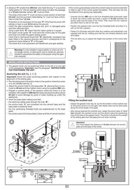
H300 mmILof a 12 mm M I2,5 mm 2 Lnessof less than 1,2 mm. Prailings or bars is over 2,5 m above the ground.- check the gate components, replace any worn or damaged partsand then lubricate them. N Oand must not inhibit the gate’s sliding action.- check that a mechanical travel limit Q(absolutely necessary) hasbeen fitted in the opening direction and that it corresponds to thePThe travel limit must guarantee anti-derailment and gate stability.Warning! It is the installer’s responsibility to check all criticaldanger points, to take action and to install any devicesneeded to guarantee the safety of all people using the gate(risk analysis).INSTALLATION INSTRUCTIONS of the passageway. ImportantINSTRUCTIONSFOR POSITIONING THE UNITAnchoring the unit (fig. 4, 5, 6)Important! Check the exact anchoring position with respect to thealignment of the sliding gate. is to be installed (see fig. 2). Atrudeby 40 mm and then tighten down using the supplied M8 nuts. installed, with a depth of 350 mm (the base should protrude by about25 mm to avoid damage by pools of water building up under theappliance). B Cbase plate is perfectly level;- the four protruding threaded bolts are perpendicular to the baseplate;- the surface area of the base plate is clean and free of cement residue.4M840 mmIf the runner guide already exists the cement base should be extendedto take in part of the runner guide foundation. This will stop the twofoundations from giving way separately.- Unscrew the four M8 nuts on the four threaded bolts (previously usedto block the anchor bolts) and leave a space of 15 mm between theanchor plate and the base of the motor. Then insert the four washersand allow them to rest on the nuts.- Position the geared motor over the four threaded bolts and allow it torest on the four washers.- Fasten it to the base using the other four washers and adjustment nutssupplied with the kit, making sure that the unit remains perfectly leveland stable.This will allow you to adjust the height and position of the motor lateron.540252 mm15 mm2532515Fitting the toothed rack110- release the geared motor (fig. 8), lay the first stretch of the toothed rackon the pinion and fix it to the gate, then fasten down all the other partsalong the entire length of the gate.- after having fastened the toothed rack, realign the pinion (play of 1 to 2mm between the toothed runner and the pinion) using the positioningnuts at the base of the geared motor. This action will prevent the weightof the sliding gate from damaging the unit when working.70Attention!15 mm between the anchorplate and the base of the motor.CBA65 211303004703325515