THM101A - FINAL AUG 20, 2004.cdr - UPM Marketing
THM101A - FINAL AUG 20, 2004.cdr - UPM Marketing
THM101A - FINAL AUG 20, 2004.cdr - UPM Marketing
- No tags were found...

Create successful ePaper yourself
Turn your PDF publications into a flip-book with our unique Google optimized e-Paper software.
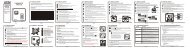
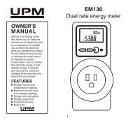
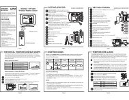
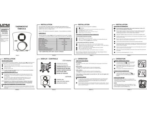
ThermostatFANON AUTO COOL OFF HEATHEHGResetSIZE AASIZE AAOWNER’SMANUALFEATURESRead and understand thismanual before installation oruse.• Easy-to-read LCD display• Easy-to-set temperaturesettings• Heat–OFF–Cool and fanauto-on switchTHERMOSTAT<strong>THM101A</strong>ThermostatFANON AUTO COOL OFF HEAT+INSTALLATIONThis thermostat can replace common residential thermostats and it isdesigned for use with most electric, oil or gas heating and air conditioningsystems that use low voltage control.Note: 2 x “AA” batteries are required for operation. Ensure batteries are installed.COMPATIBILITYGenerally, equipment with low voltage control is compatible with the thermostat. For detailson compatibility of your particular equipment, please call technical support at 1-888-468-6876.System TypeGas - Standing PilotGas - Electronic IgnitionGas - Fire BoilerGas - Millivolt SystemOil - Fire BoilerOil - Fire FurnaceElectric FurnaceElectric Air ConditionerBaseboard Electric Heater (1<strong>20</strong>/240 V)Heat Pump/Multi-stage equipment* NOT COMPATIBLE WITH ANY 1<strong>20</strong>/240 V CIRCUIT.Compatible with thermostatYesYesSome modelsYesSome modelsYesYesYesNoNoINSTALLATIONThe following tools may be required for installation:( ) screwdriverMasking tape (To wrap the exposed wires temporarily and labeling the disconnected wires)Wire stripper/cutter (If necessary, to strip wires)Power drill with a 3/16” bit (If necessary, to drill holes on the wall)Level (If necessary, to level the thermostat)CHOOSING A LOCATION FOR A NEW THERMOSTATThis thermostat should be mounted:Approximately 5’ (1.5 m) from the floor.Near or in a frequently occupied room, preferably on an inside partitioning wall.On a section of the wall without pipes or duct-work.This thermostat should NOT be mounted:Near a window, on an outside wall, or next to a door leading outside.Exposed to direct light or heat from the sun, lamp, fireplace, or other heat radiatingobjects which may cause false readings.Near or in a direct airflow from supply registers and return-air grilles.Near concealed pipes and chimneys.In areas of poor air circulation, such as behind a door or in an alcove.After choosing a location for the new thermostat, you may arrange to have aheating contractor install the control wiring for you.INSTALLATIONREPLACING OLD THERMOSTAT*Do not operate the cooling system when outside temperature is below 10°C(50 °F) to avoid damaging the compressor.Test the system to make sure that your heating and cooling systems are workingproperly before installation. If either does not work, contact a local heating/airconditioning service person to fix the problem before installation.TURN OFF POWER to system at the furnace, or at the fuse/circuit breaker panel.Carefully unpack your new thermostat and mounting plate; save package of screws,instructions and receipt.Remove cover from old thermostat. If it does not snap off when pulled firmly from thebottom, check for a screw used to secure the cover.Loosen screws holding thermostat to the wall and lift away the thermostat.Disconnect wires from old thermostat or sub-base. As you disconnect each wire, usemasking tape to label it with the old terminal designation. If there are only two wires,they don't need to be labeled.If there is an extra wire that is not connected to your old thermostat, then you won'tneed to connect it to the new thermostat.Take care not to let the wires fall back into the wall or let the ends of the wires touchone another.The wires are usually designated 'W', 'Y', 'G', 'R’PAGE 1 PAGE 2 PAGE 3 PAGE 4INSTALLATIONBATTERY INSTALLATION2 “AA” size batteries are required for operation. The battery symbol ( ) will flash when thebatteries are low. It is recommended that the batteries be replaced at least once a year.Remove the back cover from the thermostat.Insert the 2 “AA” size batteries into the battery compartment following the correctpolarity as marked.Re-attach the back cover.NOTE: To select the temperature display format in °C or °F, it must be done immediatelyfollowing the battery installation.SELECTING THE DISPLAY IN ° C or ° FImmediately following the battery installation, the thermostat will enter the °C/°Fselection mode. The current temperature will appear with the temperature scale(in °C) flashing.Turn the dial left or right to select the desired temperature scale (in °C or °F).Otherwise, if no choice is made within 12 seconds, °C will automatically beselected, and the thermostat will go to its operation mode.NOTE: Selecting the °C or °F display is a one-time process. Therefore, if you wish tochange it at a later time, you will need to reset the thermostat by pressing theRESET key above the battery compartment and select °C or °F using the dial.ATTACHING THE THERMOSTAT TO THE BACK COVERAttach the thermostat body to the back cover (that is already installed on the wall) bycarefully aligning the two pieces and firmly snapping the 4 latches at the back of thethermostat.DISPLAY / CONTROLSLCD display121 TEMPERATURE DISPLAY3 2 LOW BATTERY INDICATOR23TEMPERATURE SCALE ( 4or F)34TEMPERATURE SETTING MODEON COOL4CURRENT TEMPERATURE MODE756 556HEAT OR COOL MODE67SYSTEM “ON” INDICATOR13 2+controls1 CONTROL DIAL2 “HEAT–OFF–COOL” SWITCH3 FAN ON/AUTO SWITCHOPERATION“HEAT–OFF–COOL” SWITCHOFF position:- If the switch is to the OFF position, both the heating and cooling system controls will beturned OFF.HEAT position:- Slide the switch to the HEAT position to control the heating system.- The “ HEAT” icon will light up when the switch is on the HEAT position.COOL position:- Slide the switch to the COOL position to control the cooling system.- The “ COOL” icon will light up when the switch is on the COOL position.If the heating or cooling system is turned ON, the “ON” icon will appear andcontinue to flash.FAN ON/AUTO SWITCHFor automatic control of the fan, set the FAN ON/AUTO switch to the AUTO position.In cooling, the fan starts/stops with the cooling equipment. In heating, the fan iscontrolled by the heating equipment and usually starts a few minutes after theheating equipment turns on.To turn on the fan manually, set the FAN ON/AUTO switch to the ON position. The fanwill run continuously to improve air ventilation. To return to automatic control, set theswitch to the AUTO position.OPERATIONCURRENT TEMPERATURE DISPLAYThe current room temperature is normally displayedon the LCD screen. The “ ” icon is lit when thecurrent room temperature is displayed.The displayed temperature range is from 0°C to 60°C(32°F to 140°F). Beyond this, the display will showeither “HI” or “LO”.The resolution of the detected temperature is 0.1°.VIEWING THE SET TEMPERATURETurn the dial left or right until it clicks once toreveal the current SET temperature. The “ ” iconwill appear and the current SET temperature will beflashing.DISPLAY AUTO-RETURNIn any setting mode, if the dial is not rotated within12 seconds, the display will automatically return to thecurrent temperature display.RESETIf the thermostat shows an abnormal display or if youwish to change the temperature scale (°C or °F), use apointed object to press the RESET key.RESETHEATHEATPAGE 8 PAGE 9 PAGE 10PAGE 11
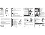
HEHGSIZE AASIZE AAINSTALLATIONMOUNTING THE THERMOSTAT BACK COVERCarefully separate the back cover from the thermostat by disengaging the 4 latchesfound at the corners on the back of the thermostat. Pull firmly but DO NOT try to pryopen with a screwdriver.The back cover should be mounted with the large hole on the top.Thread the existing wiring through the large hole from the back and set the backcover flat on the wall.Select two appropriate mounting holes and mark the locations with a pencil. Ifnecessary, use a level to make sure the thermostat is leveled.Remove the back cover from the wall and drill two 3/16” holes in the marked screwpositions.Insert the wall anchors into the holes completely. If necessary, use a hammer totap-in lightly.Mount the back cover, with the two screws, to the wall. Make sure the terminals areon the top-half of the back cover.LEVELINSTALLATIONCONNECTING THE WIRES TO THE TERMINALSTURN OFF POWER to system at the furnace, or at the fuse/circuit breaker before wiring.Connect the previously labeled wires to the corresponding terminals, matching thedesignations. Use a screwdriver to securely fasten the wires onto the terminals. Make surethe wires do not short-circuit with other terminals.Depending on your heating/cooling equipment, you mayWallneed to connect 2 to 5 wires to the thermostat.If your old thermostat has a ‘C’ wire, please wrap it withelectrician’s tape as it is not used with this thermostat.WiresIf you have both an ‘R’ and ‘Rc’ wire, you may connectMetalterminalsthem together to the ‘R’ terminal of the thermostat.If you are unsure of the connections, or for newBack coverinstallation, you may refer to the wiring diagrams below.WIRING DIAGRAM2-wire heatingHeating Relay4-wire heating/coolingINSTALLATIONSETTING THE FAN OPERATION JUMPERDepending on your home’s heating system, you may need to change the jumper setting forthe fan operation. The jumper is located above the battery compartment.HG - Use this setting for gas or oil-fired furnaces. This setting allows the fanoperation to be controlled by the heating system; not the thermostat. This is thecorrect setting for most systems.HE - Use this setting for electric heating systems. With this setting, the thermostatwill turn on the fan immediately with the heating system.The jumper is pre-installed in the ‘ HG’ position as a factory default. So there is no need tochange the jumper if this is the correct setting.To change the jumper setting, pull out the small black rectangular block and align it to thenew position and push in fully.ResetHEMetal terminals++ Mark the locationswith a pencilFan Relay3-wire heatingFan RelayCooling RelayHeating RelayHGDisengage the latches toseparate the back coverfrom the thermostatBack coverHeating RelayOPERATIONPAGE 5 PAGE 6 PAGE 7TEMPERATURE SETTINGTurn the dial left or right until it clicks once to enter the temperature1 setting mode. The “ ” icon will appear, and the display will now showthe current SET temperature flashing.2Turn the dial left or right to adjust to the desired set temperature.The temperature can be set in increments of 0.5°.The temperature setting range is from 5°C to 35°C (41°F to 95°F).NOTE: The display will automaticallyreturn to the current temperature display12 seconds after the choice has beenmade.NOTE: There is a built-in delay action to protect the heating and cooling systems.- When the heating system is ON, it will keep on running for at least 2 minutes even if thereis a change in the temperature setting.- When the heating system is OFF, it will remain OFF for at least 2 minutes before it cancome back ON.- When the cooling system is ON, it will keep on running for at least 4 minutes even if thereis a change in the temperature setting.- When the cooling system is OFF, it will remain OFF for at least 4 minutes before it cancome back ON.HEATTROUBLESHOOTINGPROBLEMLCD screen is blank.The battery symbol (flashing.Heat will not come on.) isHeat will not come on but the“ ON” icon is flashing.Air conditioning will not come on.Air conditioning will not come onbut the “ ON” icon is flashing.SOLUTION- Check if the batteries are installed correctly.- Check if the batteries are fresh and of the correct type.- Press the RESET key on the back of the thermostat above the battery compartment.- This is an indication that the batteries are running low. Replace with fresh alkalinebatteries.- Note: We recommend to have the batteries replaced at least once a year even if the batterysymbol is not flashing.1) Check and ensure that the thermostat is set to the HEAT mode.2) Check and ensure that the set temperature is higher than the current (room) temperature.3) You may have to wait up to 2 minutes before the heat will turn on. The thermostat has abuilt-in time delay to prevent undesirable on/off sequences.4) After a 2-minute wait, the heating should now be on. Whenever the heating system isrunning, the “ ON” icon will be flashing.1) Check if the furnace switch and/or pilot flame is turned on, as it may have been turned off.2) Allow several minutes for the heating system to heat up and the fan to activate. Mostheaters will heat up the system for a short while before warm air can be ventilated by thefan. Also check that the HE/HG setting is set correctly. (Refer to page 7).3) If the heat still does not come on, check the wiring installation again. (Refer to page 6).1) Check and ensure that the thermostat is set to the COOL mode.2) Check and ensure that the set temperature is lower than the current (room) temperature.3) You may have to wait up to 5 minutes before the air conditioning will turn on. Thethermostat has a built-in time delay to protect the air conditioner compressor fromundesirable on/off sequences.4) After a 5-minute wait, the air conditioning should now be on. Whenever the coolingsystem is running, the “ ON” icon will be flashing.1) Check if the air conditioning system’s main switch is turned on, as it may have beenturned off.2) Wait several minutes for the air conditioning system to activate. If the air conditioning stilldoes not come on, check the wiring installation again. (Refer to page 6).LIMITED ONE-YEAR WARRANTY<strong>UPM</strong> warrants this product, excluding battery, to be free from defects in the materials or workmanship, under normal use andservice, for a period of one (1) year from the date of purchase by the consumer.If, at any time during the warranty period, the product is defective or malfunctions, <strong>UPM</strong> shall repair or replace it (at <strong>UPM</strong>'sdiscretion) within a reasonable period of time.If the product is defective,(i) return it, with a dated proof of purchase, to the retailer from which you purchased it, or(ii) package it carefully, along with a dated proof of purchase and a short description of the malfunction, and mail it, postageprepaid, to the following address:<strong>UPM</strong> <strong>Marketing</strong> Inc.Return GoodsUnit 10B - 250 Shields CourtMarkham, OntarioL3R 9W7This warranty does not cover removal or reinstallation costs. This warranty shall not apply if it is shown by <strong>UPM</strong> that the defect ormalfunction was caused by damage which occurred while the product was in the possession of the consumer.<strong>UPM</strong>'s sole responsibility shall be to repair or replace the product within the terms stated above. <strong>UPM</strong> SHALL NOT BE LIABLEFOR ANY LOSS OR DAMAGE OF ANY KIND, INCLUDING ANY INCIDENTAL OR CONSEQUENTIAL DAMAGES RESULTING,DIRECTLY OR INDIRECTLY, FROM ANY BREACH OF ANY WARRANTY, EXPRESS OR IMPLIED, OR ANY OTHER FAILURE OFTHIS PRODUCT. Some states do not allow the exclusion or limitation of incidental or consequential damages, so this limitationmay not apply to you.THIS WARRANTY IS THE ONLY EXPRESS WARRANTY <strong>UPM</strong> MAKES ON THIS PRODUCT. THE DURATION OF ANY IMPLIEDWARRANTIES, INCLUDING THE WARRANTIES OF MERCHANTABILITY AND FITNESS FOR A PARTICULAR PURPOSE, ISHEREBY LIMITED TO THE ONE YEAR DURATION OF THIS WARRANTY. Some states do not allow limitations on how long animplied warranty lasts, so the above limitation may not apply to you.This warranty gives you specific legal rights, and you may have other rights which may vary from state to state.If you have any questions concerning this warranty, please write to:<strong>UPM</strong> <strong>Marketing</strong> Inc.Customer Service DepartmentUnit 10B - 250 Shields CourtMarkham, OntarioL3R 9W7Or call 1-888-GO-TO-<strong>UPM</strong> (1-888-468-6876), Monday to Friday, from 9:00am to 5:00pm eastern.PAGE 12 PAGE 13 PAGE 14
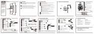
ThermostatFANON AUTO COOL OFF HEATHEHGResetSIZE AASIZE AAGuided'utilisationCARACTÉRISTIQUESVeuillez lire et vous assurerde comprendre parfaitementce manuel avant d'installerou d'utiliser le thermostat.• Afficheur à CL très lisible.• Température facile àrégler.• Modes chauffage, arrêt etclimatisation etcommutateur de contrôleautomatique duventilateur.THERMOSTAT<strong>THM101A</strong>ThermostatFANON AUTO COOL OFF HEAT+INSTALLATIONCe thermostat remplace la plupart des thermostats résidentiels communs etest conçu pour la plupart des systèmes de basse tension à gaz, au mazoutet électriques.Remarque : Ce thermostat requiert deux piles « AA » pour fonctionner.Assurez-vous qu'elles sont bien installées.COMPATIBILITÉEn règle générale, les appareils à circuit de commande basse tension sontcompatibles avec ce thermostat. En cas de doute sur la compatibilité de votreappareil de chauffage ou de climatisation, communiquez avec notre servicetechnique au 1-888-468-6876.Type de systèmeGaz – veilleuse continueGaz – allumage électroniqueGaz – chaudière à eau chaudeGaz – système à circuit basse tension (millivolt)Mazout – chaudière à eau chaudeMazout – air pulséÉlectrique – air pulséClimatiseur électriquePlinthes électriques (1<strong>20</strong>/240 V)Thermopompe/Systèmes à phases multiplesCompatible avec le thermostatOuiOuiCertains modèlesOuiCertains modèlesOuiOuiOuiNonNon*N'EST PAS COMPATIBLE AVEC LES SYSTÈMES 1<strong>20</strong>/240 V.INSTALLATIONVoici les outils dont vous pourriez avoir besoin pour l'installation du thermostat :Un tournevis à pointe cruciforme ( )Du ruban-cache (Pour envelopper temporairement le bout des fils et identifier les fils)Une pince coupe-fil/à dénuder (pour dénuder les fils, au besoin)Une perceuse électrique avec mèche de 3/16 po (pour percer des trous dans le mur, au besoin)Un niveau (pour mettre le thermostat parfaitement à l'horizontale)CHOIX D'UN EMPLACEMENT CONVENABLE POUR UN NOUVEAU THERMOSTATLe thermostat devrait être monté :à environ 1,5 m (5 pi) du plancher.dans une pièce très fréquentée ou près de celle-ci, préférablement sur une cloison intérieure.contre un mur qui ne dissimulede tuyaux ou de conduites.PAGE 1 PAGE 2PAGE 3 PAGE 4pasÉVITEZ d'installer le thermostat :près d'une fenêtre, contre un mur extérieur ou près d'une porte qui mène à l'extérieur.contre un mur exposé à la chaleur du soleil, d'une lampe, d'un foyer ou autres sources dechaleur qui pourraient fausser la lecture.près d'une bouche de chauffage ou d'un conduit de reprise ou dans le courant d'air généré parceux-ci.contre un mur qui dissimule des tuyaux ou une cheminée.dans un endroit où la circulation d'air est réduite, derrière une porte ou dans une alcôve parexemple.Après avoir choisi un emplacement pour votre nouveau thermostat, vous pouvez sivous le désirez faire appel à un technicien pour le raccordement des fils.INSTALLATIONREMPLACEMENT DE L'ANCIEN THERMOSTATPour éviter d'endommager le compresseur, ne faites pas fonctionner le système*oode climatisation lorsque la température extérieure est inférieure à 10 C (50 F).Avant d'installer le thermostat, vérifiez tout d'abord si les systèmes de chauffage et declimatisation fonctionnent normalement. S'il yaunproblème, faites réparer lesystème par un réparateur avant de remplacer le thermostat.COUPEZ LE COURANT au système de chauffage ou au panneau de disjoncteurs oude fusibles.Ouvrez soigneusement l'emballage du nouveau thermostat, qui comprend uneplaque de montage, un sachet de vis et des instructions. Conservez la facture.Retirez le couvercle de l'ancien thermostat. S'il ne s'enlève pas lorsqu'on le force unpeu vers le bas, vérifiez si une vis retient le couvercle et enlevez-la.Desserrez les vis qui retiennent le thermostat au mur et dégagez-le de sa plaque demontage.Débranchez les fils de l'ancien thermostat ou de sa plaque de montage. Identifiezchaque fil avec du ruban-cache en écrivant la désignation du connecteur où il étaitbranché. S'il n'y a que deux fils, il n'est pas nécessaire de les identifier.S'ilyaunfilsupplémentaire qui n'est pas raccordé à l'ancien thermostat, il n'aura pasnon plus à être raccordé au nouveau.Faites attention de ne pas laisser les fils se rétracter dans le mur et ne laissez pas lesfils se toucher entre eux.Les fils sont généralement désignés «W»,«Y»,«G»et«R».INSTALLATIONINSTALLATION DES PILESCe thermostat fonctionne sur deux piles « AA ». Lorsque les piles sont faibles, le symbole depile ( ) clignote. Il est recommandé de remplacer les piles une fois l'an.Détachez le thermostat de la plaque arrière.Installez deux piles « AA » dans le compartiment à piles, selon la polarité indiquée.Remettez le thermostat sur la plaque arrière.ooRemarque : Le choix de l'échelle de température ( C ou F) doit être fait immédiatementaprès l'installation des piles.ooCHOIX DE L'ÉCHELLE DE TEMPÉRATURE ( C ou F)Immédiatement après l'installation des piles, le thermostat se mettra en mode desélection de l'échelle de température. La température ambiante apparaîtra àol'affichage et le symbole « C » clignotera.Tourner la molette vers la droite ou la gauche pour sélectionner l'échelle detempérature désirée (in °C or °F). Autrement, si aucun choix n'est fait dans les 12secondes, °C sera automatiquement sélectionné, et le thermostat fonctionnera à sonmode de fonctionnement.REMARQUE : La sélection de l'échelle de température °C ou °F ne se fait qu'une fois audémarrage. Par conséquent, si vous désirez la changer plus tard, vous devrez réinitialiserle thermostat en appuyant sur la touche RESET au-dessus du compartiment à piles etsélectionner °C ou °F en utilisant la molette.POUR FIXER LE THERMOSTAT À LA PLAQUE ARRIÈREPour fixer le boîtier du thermostat à la plaque arrière déjà vissée au mur, il suffit debien aligner les deux parties et d'enclencher les quatre languettes dans le dos duthermostat.AFFICHAGE / COMMANDESaffichage à CL1234ON COOLHEAT76 513 2+1234567Affichage de la températureIndicateur de pile faibleooÉchelle de température ( C ou F)Mode de réglage de températureMode de températureMode de chauffage ou declimatisationIndicateur de marchecommandes1 Molette de commande2 Commutateur chauffage-arrêtclimatisation3 Commutateur du ventilateur -marche/autoFONCTIONNEMENTCOMMUTATEUR CHAUFFAGE-ARRÊT-CLIMATISATIONPosition OFF- Si le commutateur est à la position OFF, les systèmes de chauffage et climatisation sont àl'arrêt.Position HEAT- Mettez le commutateur en position HEAT pour mettre en marche le système de chauffage.- Le symbole “HEAT” apparaît à l'affichage lorsque le commutateur est en position HEAT.Position COOL-Mettez le commutateur en position COOL pour mettre en marche le système de climatisation.- Le symbole “COOL” apparaît à l'affichage lorsque le commutateur est en position COOL.Si le système de chauffage ou de climatisation est en marche (ON), lesymbole “ON” clignotera à l'affichage.COMMUTATEUR DU VENTILATEUR - MARCHE/AUTOPour un contrôle automatique du ventilateur, mettez le commutateur du ventilateur enposition AUTO (FAN). En mode de climatisation, le ventilateur se met en marche ets'arrête à la demande du climatiseur. En mode de chauffage, le ventilateur estcommandé par le système de chauffage et se met généralement en marche aprèsquelques minutes de préchauffage.Pour un contrôle manuel du ventilateur, mettez le commutateur du ventilateur enposition ON. Le ventilateur sera alors continuellement en marche pour assurer unebonne ventilation. Pour revenir en mode automatique, placez le commutateur à laposition AUTO.FONCTIONNEMENTAFFICHAGE DE LA TEMPÉRATURE AMBIANTELa plupart du temps, c'est la température ambiantequi est indiquée sur l'affichage à CL. Le symbole ( )apparaît à l'affichage lorsque la température ambianteest affichée.oLa plage de température de l'affichage est de 0 C ào o o60 C (32 F à 140 F). Si la température est inférieureou supérieure à ces valeurs, le thermostat affichera LOou HI.La sensibilité du thermostat est de 0,1 oPOUR VOIR LE RÉGLAGE DE LA TEMPÉRATURETourner la molette vers la droite ou la gauche jusqu'à cequelle clique une fois pour révéler l'actuelle températureréglée. L'icône “ ” apparaîtra et l'actuelle températureréglée clignotera.RETOUR AUTOMATIQUE DE L'AFFICHAGEDans n'importe quel mode de réglage, si la molette n'est pastournée pendant 12 secondes, l'affichage retourneraautomatiquement à celui de la température actuelle.RÉARMEMENTSi le thermostat affiche un affichage anormal ou si vousdésirez changer l'échelle de température (°C ou °F), utilisezun objet pointu pour appuyer sur la touche RÉARMEMENT(RESET).RÉARMEMENTHEATHEATPAGE 8 PAGE 9 PAGE 10PAGE 11
HEHGSIZE AASIZE AAINSTALLATIONINSTALLATION DE LA PLAQUE ARRIÈREDétachez soigneusement la plaque arrière du thermostat en dégageant les quatrelanguettes de retenue fixées dans les coins, au dos de la plaque arrière. Tirezfermement, mais SANS vous aider d'un tournevis.La plaque arrière doit être fixée au mur le grand trou vers le haut.Passez les fils par le grand trou au centre et tenez la plaque bien à plat contre le mur.Choisissez deux trous de montage et faites des marques sur le mur au moyen d'uncrayon. Aidez-vous d'un niveau pour vous assurer que la plaque est parfaitementhorizontale.Retirez la plaque et percez deux trous de 3/16 po aux endroits où vous avez fait desmarques au crayon.Insérez des chevilles dans les trous et enfoncez-les complètement. Tapotez-les avecun marteau au besoin.Fixez la plaque au mur au moyen des deux vis fournies. Assurez-vous que lesconnecteurs sont bien en haut.NIVEAUConnecteursmétalliquesDégagez les languettes deretenue pour détacher laplaque arrière du thermostat.++Marquezl'emplacementdes trous avecun crayon.Plaque arrièreINSTALLATIONRACCORDEMENT DES FILS AUX CONNECTEURSCOUPEZ LE COURANT au système de chauffage ou au panneau de disjoncteurs ou de fusiblesavant d'effectuer le raccordement des fils.Raccordez les fils (que vous avez préalablement identifiés) aux connecteurs correspondants. Utilisezun tournevis pour serrer fermement les fils. Assurez-vous que chaque fil ne touche qu'à un seulconnecteur.Selon votre type de système de chauffage ou de climatisation, vousMuraurezàraccorderde2à5fils au thermostat.Si votre ancien thermostat comporte un fil «C»,veuillez enroulersa partie exposée de ruban d'électricien et le laisser de côté : cefil n'est pas nécessaire avec ce type de thermostat.FilsConnecteursSivousdisposezd'unfil«Rc»etd'unfil«R»,vouspouvezlesmétalliquesraccorder tous les deux au connecteur «R»duthermostat.Si vous n'êtes pas certain des raccordements ou s'il s'agit d'unePlaquenouvelle installation, référez-vous au guide de câblage ci-dessous.arrièreDIAGRAMME DE CÂBLAGEChauffage 2 filsRelais duChauffage/climatisation 4 filschauffageRelais duventilateurRelais de laclimatisationChauffage 3 filsRelais duchauffageRelais duventilateurRelais duchauffageINSTALLATIONRÉGLAGE DU CAVALIER D'ACTIVATION DU VENTILATEURSelon le système de chauffage de votre domicile, vous pourriez avoir à modifier la positiondu cavalier pour l'activation du ventilateur. Le cavalier est situé au-dessus du compartiment àpiles.HG – placez le cavalier à cet endroit pour les systèmes de chauffage au gaz ou aumazout. Ce réglage donne le contrôle du ventilateur au système de chauffage plutôtqu'au thermostat. Ce réglage vaut pour la plupart des systèmes.HE – placez le cavalier à cet endroit pour les systèmes de chauffage électriques. Sousce réglage, le thermostat actionne le ventilateur en même temps que le chauffage.Le cavalier sera déjà en position HG, car c'est le réglage par défaut qu'on lui donne à l'usine.Il est donc inutile de changer le réglage si votre système de chauffage est au gaz ou aumazout.Si vous devez changer le réglage, sortez le petit bloc noir rectangulaire et placez-le dans sanouvelle position en le poussant à fond.ResetHEHGFONCTIONNEMENTPAGE 5 PAGE 6 PAGE 7RÉGLAGE DE LA TEMPÉRATURETourner la molette vers la droite ou la gauche une fois pour passer en1 mode de réglage de la température. Le symbole ( ) apparaîtra et leréglage actuel clignotera à l'affichage.2Tourner la molette vers la droite ou la gauche jusqu'à la température voulue.La température peut être réglée au demi-degré près.o o o oLa température peut être réglée entre 5 C et 35 C (41 F à 95 F).REMARQUE : L'affichage retourneraautomatiquement à celui de la températureactuelle 12 secondes après que le choixaura été fait.REMARQUE : Le thermostat comprend un délai de sécurité pour protéger le systèmede chauffage et de climatisation :- Lorsque le système de chauffage est activé, il continuera de fonctionner pendant au moins2 minutes même si le réglage de température est modifié.- Lorsque le système de chauffage est désactivé, il demeurera désactivé pendant au moins2 minutes avant de s'allumer.- Lorsque le système de climatisation est activé, il continuera de fonctionner pendant aumoins 4 minutes même si le réglage de température est modifié.- Lorsque le système de climatisation est désactivé, il demeurera désactivé pendant aumoins 4 minutes avant de s'allumer.HEATDÉPANNAGEPROBLÈMEL'affichage ne s'allume pas.Le symbole de pile ( )clignote.Le système de chauffage ne semet pas en marche.Le système de chauffage ne semet pas en marche, mais lesymbole ON clignote.Le système de climatisation nese met pas en marche.Le système de climatisation ne semet pas en marche, mais lesymbole ON clignote.SOLUTION- Vérifiez si les piles sont bien installées.- Assurez-vous que les piles sont en bon état et qu'elles sont du bon type.- Appuyez sur le bouton de RÉARMEMENT situé au dos du thermostat, au-dessus ducompartiment à piles.- Les piles sont faibles. Remplacez-les avec des piles alcalines neuves.- Remarque : On recommande de remplacer les piles une fois l'an, même si l'indicateur depile faible ne clignote pas.1) Assurez-vous que le thermostat est réglé à HEAT.2) Vérifiez si la température ambiante n'est pas supérieure à celle qui est programmée.3) Vous pourriez avoir à attendre jusqu'à 2 minutes avant que le chauffage ne démarre. Lethermostat est doté d'un dispositif de sécurité qui prévient les mises en marche et arrêtsrépétés.4) Le chauffage devrait démarrer après 2 minutes. Lorsque le système de chauffage est enmarche, le symbole ON clignotera.1) Assurez-vous que l'interrupteur du système de chauffage est à ON et que la veilleuse esten marche.2) Accordez au système un peu de temps pour démarrer. La plupart des systèmes ont uncycle de préchauffage avant l'activation du ventilateur. Le cavalier HE/HG du thermostatest incorrectement réglé. (Voir à la page 7).3) Si le système ne démarre toujours pas, vérifiez encore une fois le câblage du thermostat.(Voir à la page 6).1) Assurez-vous que le thermostat est réglé à COOL.2) Vérifiez si la température ambiante n'est pas inférieure à celle qui est programmée.3) Vous pourriez avoir à attendre jusqu'à 5 minutes avant que le climatiseur ne démarre. Lethermostat est doté d'un dispositif de sécurité qui prévient les mises en marche et arrêtsrépétés.4) La climatisation devrait démarrer après 5 minutes. Lorsque le système de climatisation esten marche, le symbole ON clignotera.1) Assurez-vous que l'interrupteur du climatiseur est à ON.2) Accordez au système un peu de temps pour démarrer. Si le système ne démarre toujourspas, vérifiez encore une fois le câblage du thermostat. (Voir à la page 6).GARANTIE LIMITÉE D’UN AN<strong>UPM</strong> garantit que ce produit, à l'exception des piles, est exempt de tout défaut matériel et de fabrication et qu'il est couvert par unegarantie limitée, dans des conditions normales d'usage et de service, pendant une période d’un an qui commence depuis la datede l'achat par le consommateur.Si à n'importe quel moment durant la période de garantie, le produit est défectueux ou ne fonctionne pas correctement, <strong>UPM</strong> le répareraou le remplacera (à la discrétion d'<strong>UPM</strong>) et ce dans une période raisonnable de temps.Si le produit est défectueux(i) Retourner le, avec la preuve datée de l'achat, au revendeur où vous l'avez acheté, ou(ii) Emballer le soigneusement, avec la preuve datée de l'achat et une courte description du mauvais fonctionnement, et envoyer letout par poste, franc de port, à l'adresse suivante:<strong>UPM</strong> <strong>Marketing</strong> Inc.Return GoodsUnit 10B - 250 Shields CourtMarkham, OntarioL3R 9W7Cette garantie ne couvre pas les frais d'enlèvement ou de réinstallation. Cette garantie ne appliquera pas s'il est prouvé par <strong>UPM</strong> que ledéfaut ou le mauvais fonctionnement aurait été causé par un dommage qui s'est produit pendant que le produit était en possession duconsommateur.La seule responsabilité d'<strong>UPM</strong> sera de réparer ou de remplacer le produit selon les termes mentionnés ci-dessus. <strong>UPM</strong> NE POURRA ENAUCUN CAS ETRE TENU RESPONSABLE POUR LES PERTES OU DOMMAGES D'AUCUNE SORTE, Y COMPRIS LES DOMMAGESINDIRECTS OU CONSECUTIFS RESULTANT DIRECTEMENT OU INDIRECTEMENT, D'UNE RUPTURE DE GARANTIE, EXPRESSE OUTACITE, OU D'UNE AUTRE DEFAILLANCE DE CE PRODUIT. Certains états n'autorisent pas l'exclusion ou la limitation de dommagesindirect ou consécutifs, alors la limitation peut ne pas vous être applicable.<strong>UPM</strong> NE FAIT AUCUNE AUTRE GARANTIE QUE CELLE PRÉVUE DANS LA PRÉSENTE GARANTIE ET EXCLUE EXPRESSÉMENT TOUTEAUTRE GARANTIE SUR CE PRODUIT. LA DUREE DES GARANTIES TACITES, Y COMPRIS LES GARANTIES COMMERCIALES ETD'APTITUDE A UN EMPLOI PARTICULIER, EST CI-APRES LIMITEE A UNE DUREE D’UN AN DE CETTE GARANTIE. Certains étatsn'autorisent pas des limitations sur la durée d'une garantie tacite, alors la limitation ci-dessus peut ne pas vous être applicable.Cette garantie vous donne des droits légaux particuliers, et vous pouvez avoir d'autres droits qui peuvent varier d'Etat à Etat.Si vous avez des questions concernant cette garantie, veuillez écrire à:<strong>UPM</strong> <strong>Marketing</strong> Inc.Customer Service DepartmentUnit 10B - 250 Shields CourtMarkham, OntarioL3R 9W7Ou téléphoner au 1-888-GO-TO-<strong>UPM</strong> (1-888-468-6876), Lundi au Vendredi de 9:00 à 17:00 heures.PAGE 12 PAGE 13 PAGE 14