THM101A - FINAL AUG 20, 2004.cdr - UPM Marketing
THM101A - FINAL AUG 20, 2004.cdr - UPM Marketing
THM101A - FINAL AUG 20, 2004.cdr - UPM Marketing
- No tags were found...

You also want an ePaper? Increase the reach of your titles
YUMPU automatically turns print PDFs into web optimized ePapers that Google loves.
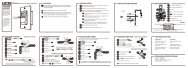
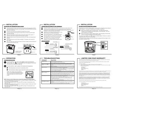
HEHGSIZE AASIZE AAINSTALLATIONMOUNTING THE THERMOSTAT BACK COVERCarefully separate the back cover from the thermostat by disengaging the 4 latchesfound at the corners on the back of the thermostat. Pull firmly but DO NOT try to pryopen with a screwdriver.The back cover should be mounted with the large hole on the top.Thread the existing wiring through the large hole from the back and set the backcover flat on the wall.Select two appropriate mounting holes and mark the locations with a pencil. Ifnecessary, use a level to make sure the thermostat is leveled.Remove the back cover from the wall and drill two 3/16” holes in the marked screwpositions.Insert the wall anchors into the holes completely. If necessary, use a hammer totap-in lightly.Mount the back cover, with the two screws, to the wall. Make sure the terminals areon the top-half of the back cover.LEVELINSTALLATIONCONNECTING THE WIRES TO THE TERMINALSTURN OFF POWER to system at the furnace, or at the fuse/circuit breaker before wiring.Connect the previously labeled wires to the corresponding terminals, matching thedesignations. Use a screwdriver to securely fasten the wires onto the terminals. Make surethe wires do not short-circuit with other terminals.Depending on your heating/cooling equipment, you mayWallneed to connect 2 to 5 wires to the thermostat.If your old thermostat has a ‘C’ wire, please wrap it withelectrician’s tape as it is not used with this thermostat.WiresIf you have both an ‘R’ and ‘Rc’ wire, you may connectMetalterminalsthem together to the ‘R’ terminal of the thermostat.If you are unsure of the connections, or for newBack coverinstallation, you may refer to the wiring diagrams below.WIRING DIAGRAM2-wire heatingHeating Relay4-wire heating/coolingINSTALLATIONSETTING THE FAN OPERATION JUMPERDepending on your home’s heating system, you may need to change the jumper setting forthe fan operation. The jumper is located above the battery compartment.HG - Use this setting for gas or oil-fired furnaces. This setting allows the fanoperation to be controlled by the heating system; not the thermostat. This is thecorrect setting for most systems.HE - Use this setting for electric heating systems. With this setting, the thermostatwill turn on the fan immediately with the heating system.The jumper is pre-installed in the ‘ HG’ position as a factory default. So there is no need tochange the jumper if this is the correct setting.To change the jumper setting, pull out the small black rectangular block and align it to thenew position and push in fully.ResetHEMetal terminals++ Mark the locationswith a pencilFan Relay3-wire heatingFan RelayCooling RelayHeating RelayHGDisengage the latches toseparate the back coverfrom the thermostatBack coverHeating RelayOPERATIONPAGE 5 PAGE 6 PAGE 7TEMPERATURE SETTINGTurn the dial left or right until it clicks once to enter the temperature1 setting mode. The “ ” icon will appear, and the display will now showthe current SET temperature flashing.2Turn the dial left or right to adjust to the desired set temperature.The temperature can be set in increments of 0.5°.The temperature setting range is from 5°C to 35°C (41°F to 95°F).NOTE: The display will automaticallyreturn to the current temperature display12 seconds after the choice has beenmade.NOTE: There is a built-in delay action to protect the heating and cooling systems.- When the heating system is ON, it will keep on running for at least 2 minutes even if thereis a change in the temperature setting.- When the heating system is OFF, it will remain OFF for at least 2 minutes before it cancome back ON.- When the cooling system is ON, it will keep on running for at least 4 minutes even if thereis a change in the temperature setting.- When the cooling system is OFF, it will remain OFF for at least 4 minutes before it cancome back ON.HEATTROUBLESHOOTINGPROBLEMLCD screen is blank.The battery symbol (flashing.Heat will not come on.) isHeat will not come on but the“ ON” icon is flashing.Air conditioning will not come on.Air conditioning will not come onbut the “ ON” icon is flashing.SOLUTION- Check if the batteries are installed correctly.- Check if the batteries are fresh and of the correct type.- Press the RESET key on the back of the thermostat above the battery compartment.- This is an indication that the batteries are running low. Replace with fresh alkalinebatteries.- Note: We recommend to have the batteries replaced at least once a year even if the batterysymbol is not flashing.1) Check and ensure that the thermostat is set to the HEAT mode.2) Check and ensure that the set temperature is higher than the current (room) temperature.3) You may have to wait up to 2 minutes before the heat will turn on. The thermostat has abuilt-in time delay to prevent undesirable on/off sequences.4) After a 2-minute wait, the heating should now be on. Whenever the heating system isrunning, the “ ON” icon will be flashing.1) Check if the furnace switch and/or pilot flame is turned on, as it may have been turned off.2) Allow several minutes for the heating system to heat up and the fan to activate. Mostheaters will heat up the system for a short while before warm air can be ventilated by thefan. Also check that the HE/HG setting is set correctly. (Refer to page 7).3) If the heat still does not come on, check the wiring installation again. (Refer to page 6).1) Check and ensure that the thermostat is set to the COOL mode.2) Check and ensure that the set temperature is lower than the current (room) temperature.3) You may have to wait up to 5 minutes before the air conditioning will turn on. Thethermostat has a built-in time delay to protect the air conditioner compressor fromundesirable on/off sequences.4) After a 5-minute wait, the air conditioning should now be on. Whenever the coolingsystem is running, the “ ON” icon will be flashing.1) Check if the air conditioning system’s main switch is turned on, as it may have beenturned off.2) Wait several minutes for the air conditioning system to activate. If the air conditioning stilldoes not come on, check the wiring installation again. (Refer to page 6).LIMITED ONE-YEAR WARRANTY<strong>UPM</strong> warrants this product, excluding battery, to be free from defects in the materials or workmanship, under normal use andservice, for a period of one (1) year from the date of purchase by the consumer.If, at any time during the warranty period, the product is defective or malfunctions, <strong>UPM</strong> shall repair or replace it (at <strong>UPM</strong>'sdiscretion) within a reasonable period of time.If the product is defective,(i) return it, with a dated proof of purchase, to the retailer from which you purchased it, or(ii) package it carefully, along with a dated proof of purchase and a short description of the malfunction, and mail it, postageprepaid, to the following address:<strong>UPM</strong> <strong>Marketing</strong> Inc.Return GoodsUnit 10B - 250 Shields CourtMarkham, OntarioL3R 9W7This warranty does not cover removal or reinstallation costs. This warranty shall not apply if it is shown by <strong>UPM</strong> that the defect ormalfunction was caused by damage which occurred while the product was in the possession of the consumer.<strong>UPM</strong>'s sole responsibility shall be to repair or replace the product within the terms stated above. <strong>UPM</strong> SHALL NOT BE LIABLEFOR ANY LOSS OR DAMAGE OF ANY KIND, INCLUDING ANY INCIDENTAL OR CONSEQUENTIAL DAMAGES RESULTING,DIRECTLY OR INDIRECTLY, FROM ANY BREACH OF ANY WARRANTY, EXPRESS OR IMPLIED, OR ANY OTHER FAILURE OFTHIS PRODUCT. Some states do not allow the exclusion or limitation of incidental or consequential damages, so this limitationmay not apply to you.THIS WARRANTY IS THE ONLY EXPRESS WARRANTY <strong>UPM</strong> MAKES ON THIS PRODUCT. THE DURATION OF ANY IMPLIEDWARRANTIES, INCLUDING THE WARRANTIES OF MERCHANTABILITY AND FITNESS FOR A PARTICULAR PURPOSE, ISHEREBY LIMITED TO THE ONE YEAR DURATION OF THIS WARRANTY. Some states do not allow limitations on how long animplied warranty lasts, so the above limitation may not apply to you.This warranty gives you specific legal rights, and you may have other rights which may vary from state to state.If you have any questions concerning this warranty, please write to:<strong>UPM</strong> <strong>Marketing</strong> Inc.Customer Service DepartmentUnit 10B - 250 Shields CourtMarkham, OntarioL3R 9W7Or call 1-888-GO-TO-<strong>UPM</strong> (1-888-468-6876), Monday to Friday, from 9:00am to 5:00pm eastern.PAGE 12 PAGE 13 PAGE 14