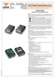
<strong>CARDIN</strong> <strong>ELETTRONICA</strong> <strong>spa</strong>Via del lavoro, 73 – Z.I. Cimavilla 31013 Codognè (TV) ItalyTel: +39/0438.404011Fax: +39/0438.401831email (Italy):Sales.office.it@cardin.itemail (Europe):Sales.office@cardin.itHttp:www.cardin.itREMARKSThese instructions are aimed at professionally qualified "installers of electricalequipment" and must respect the local standards and regulations in force.The use and installation of these appliances must rigorously respect the indicationssupplied by the manufacturer and the safety standards and regulations in force.Attention! Only for EU customers - WEEE marking.This symbol indicates that once the products life-<strong>spa</strong>n has expiredit must be disposed of separately from other rubbish.The user is therefore obliged to either take the product to a suitabledifferential collection site for electronic and electrical goods or tosend it back to the manufacturer if the intention is to replace it witha new equivalent version of the same product.Suitable differential collection, environmental friendly treatment and disposalcontributes to avoiding negative effects on the ambient and consequently healthas well as favouring the recycling of materials. Illicitly disposing of this productby the owner is punishable by law and will be dealt with according to the lawsand standards of the individual member nation.DESCRIPTIONModulated infrared barrier consisting of a transmitter and a receiver. The equipmentis housed in a shockproof and waterproof plastic casing. The lenses can be adjustedthrough 180° horizontally and plus or minus 30° vertically. These adjustments permitlateral fitting and installations where the transmitter and receiver are at differentheights (see detail e-d, fig.2)USEThe infrared barrier constitutes an efficient safety system for the protection of passagewaysor <strong>spa</strong>ces which are equipped with automatic door or gate systems. It issuitable for systems which have a passing room of not more than 60m.VERSIONSCDR851: The package contains the components required for surface installations- 1 Transmitter + 1 Receiver in a basic container- 2 Glass enclosing covers for externally located photoelectric cells- 2 Fast-fitting wall mounting brackets- Set of screws and gasketsKIT841VEI The package contains the components required for embedding- 2 Embedding containers- 2 Glass enclosing covers for embedded photoelectric cells- Set of screws and gaskets- 2 Galvanized metal hooks (for embedding installations on columns)OPTIONAL ACCESSORIESCDR841ABC Shock-proof plastic protection (for surface flush fitting)TECHNICAL SPECIFICATIONS- Infrared emission obtained through the use of a double emitter GaAs (GaliumArsenide) diode with continuous modulation at 6,75 KHz.- Infrared emission wavelength: 950 nm.- Power supply: 12 - 24Vac/dc.- Command: double relay with serial exchange.- Maximum commutable power of relay with resistive load:28W in dc/60VA in ac - Max. voltage 40V ac/dc- Power consumption:12V ac/dc, 45 mA for the receiver + 50 mA for the transmitter24V ac/dc, 50 mA for the receiver + 58 mA for the transmitter- Operating temperature: -10…+55°C.- Red led indicating that the transmitter is receiving power.- Red led (photocells out of alignment or the beam is interrupted) for the receiver.- Test point (for fine tuning) on the receiver.- Sensitivity regulation trimmer.- Adjustable lens on self lubricating and self locking ball joint.- Protection grade IP55.- Range: 60 m under all weather conditions such as thick fog, rain, dust etc.INSTALLATIONNote: In cases where the installation consists of more than one device the followingmust be taken into account. Two receivers installed on the same side can beoperated by one single transmitter on the opposite side without compromising thecorrect functioning of the system. If this situation occurs unintentionally (i.e. tworeceivers installed on one side and a transmitter, which has to operate only one of theSERIAL NUMBERZVL239.02SERIESMODULATED INFRARED BARRIERMODELDATECDR 851 16.09.2009This product has been tried and tested in the manufacturer's laboratory, during theinstallation of the product follow the supplied indications carefully.receivers, on the other side) then care must be taken to maintain the correct distancebetween the transmitters and the receivers (minimum 600m). The transmitter andreceiver are normally positioned frontally on the same geometrical axis and at thesame height from the ground.Surface mounted installation CDR851 (fig. 4)- Installation is possible on all types of structure. Other than the standard alignedpositioning the device can also be positioned both laterally (moving the device outof the passageway) and at different heights in order to solve problems posed bydifferent structures ( detail a-b-c-d, fig.2).- Choose the points at which the devices are to be surface mounted, according tothe requirements of the system.- Work out the run of the cables from the structure to the point of connection.- Fix the fast-fitting brackets at the chosen points (detail 1, fig. 4).- Pass the connecting cables through the hole in the base of the case.- Move the p.c.b. card slightly then wire up and connect the cables.- Once the device has been wired up, snap the case to the fast-fitting bracket, rememberingto place the waterproof seal between the case and the bracket. The jointbetween the case and the bracket is guaranteed to be waterproof (detail 2, fig. 4).- Insert the sealing gasket into its seat on the case, carry out any eventual adjustmentsand then fit the glass enclosing cover into place (detail 5-6, fig. 4).- If required fit the optional protective covering which is available on request (detail7, fig. 4).Embedded installation CDR851+KIT841VEI (fig. 5)- Installation is possible on all types of structure.- Choose the points at which the devices are to be surface mounted, according tothe requirements of the system.- Excavate the seat for embedding according to the dimensions of the case (detail1, fig. 5).- Work out the run of the cables from the structure to the point of connection.- Pass the cables through the wall and fasten down.- Pass the connecting cables through the hole in the base of the case.- Move the p.c.b. card slightly then wire up and connect the cables.- Once the device has been wired up, insert the base case into the embedding caseand press the two together until the reference pins coincide with the correspondingholes (detail 1-2, fig.5).- Insert the sealing gasket into its seat on the case, carry out any eventual adjustmentsand then fit the glass enclosing cover into place (detail 4-5, fig. 4).ADJUSTMENT AND FINE TUNINGThe appliance is fitted with a trimmer for sensitivity adjustment “A” fig. 6.Note: The appliance is supplied with the sensitivity set to minimum.A reduction in sensitivity is obtained by rotating the trimmer clockwise. An increasein sensitivity is obtained by rotating the trimmer anticlockwise. Normally an increasedworking distance requires greater sensitivity. Bear in mind that at reduced distances ahigh sensitivity level will delay the tripping of the relay. This could mean that a relativelysmall object travelling rapidly and crossing the beam may not activate the securityrelay. Therefore the sensitivity should be adjusted when centring the photo-electriccells and considering the following:- The operating distance.- The relay trip speed.- The exact centring of the system.CONNECTIONS AND CENTRING- Wire up the device according to the indications shown in fig.3. Remove the p.c.b.card slightly to facilitate this operation.- Replace the p.c.b. card.- Once the power has been turned on the following will occur:the transmitter led will remain permanently lit and, if the receiver is not aligned,the receiver led will also be lit.- The minimum cable cross section area for the transmitter/receiver = 0.2 mm 2(AWG #24)Centring should be carried out as follows1) Place the probes over the test point (fig. 6) maintaining the correct polarity asindicated on the p.c.b. card (lowest setting 2 Vdc).2) Set the sensitivity adjustment trimmer to a level which registers minimum tensionon the tester.3) Orientate the lens so as to obtain the maximum signal deviation.4) Compensate for the excess or lack of sensitivity by adjusting the trimmer until themaximum signal deviation falls between 1 and - 1,5 Vdc.
<strong>CARDIN</strong> <strong>ELETTRONICA</strong> <strong>spa</strong>Via del lavoro, 73 – Z.I. Cimavilla 31013 Codognè (TV) ItalyTel: +39/0438.404011Fax: +39/0438.401831email (Italy):Sales.office.it@cardin.itemail (Europe):Sales.office@cardin.itHttp:www.cardin.itAVERTISSEMENTCe livret est destiné à des personnes titulaires d’un certificat d’aptitude professionnellepour l’installation des "appareils électriques" et requiert une bonne connaissance de latechnique appliquée professionnellement. L’emploi et l’installation de cet appareil doiventrespecter rigoureusement les indications fournies par le constructeur et les normes desécurité en vigueur.Attention! Seulement pour les clients de l'EU - Marquage WEEE.Ce symbole indique l’obligation de ne pas éliminer l’appareil, à la fin desa durée de vie, avec les déchets municipaux non triés et de procéder àsa collecte sélective. Par conséquent, l’utilisateur doit remettre l’appareilà un centre de collecte sélective des déchets électroniques et électriquesou au revendeur qui est tenu, lorsqu’il fournit un nouvel appareil, de faire en sorteque les déchets puissent lui être remis, sur une base de un pour un, pour autant quel’appareil soit de type équivalent à celui qu’il fournit. La collecte sélective des équipementsélectriques et électroniques en vue de leur valorisation, leur traitement et leurélimination dans le respect de l’environnement contribue à éviter la nocivité desditséquipements pour l’environnement et pour la santé et à encourager leur recyclage.L’élimination abusive de l’équipement de la part du détenteur final comporte l’applicationdes sanctions administratives prévues par les normes en vigueur dans l’ÉtatMembre d’appartenance.DESCRIPTIONBarrière à infrarouge modulé composée de projecteur et récepteur. Les appareils sontconte nus dans un boî tier en plastique antichoc, étanche à l'eau et prévue pour tous lessystèmes de fixation. L’optique est réglable, aussi bien horizontalement, en pouvant effectuerune rotation de 180°, que verticalement avec une rotation possible de ±30° parrap port à la po si tion stan dard. Ces deux ré gla ges per met tent des in stal la tions avec fonctionne ment la té ral par rap port au plan de fixa tion et des in stal la tions avec pro jec teur etrécepteur positionnés sur différentes hauteurs (détails e-d, fig. 2).POSSIBILITÉ D’EMPLOILa barrière à rayon infrarouge représente un système efficace en ce qui concerne la protectionde passages ou e<strong>spa</strong>ces pour lesquels sont prévues des installations automatiséesde por tes ou por tails contrô lés à dis tan ce. Son ap pli ca tion est in di quée pour une dis tan cede passage maximum non supérieure à 60m.VERSIONSCDR851 La confection comprend les éléments pour l'application en surface- 1 Projecteur + 1 Récepteur dans boîte de base- 2 Lamelles de verre de fermeture pour cellules photoélectriques d'extérieur- 2 Plaquettes pour fixation rapide sur paroi- Visseries et jointsKIT841VEI La confection comprend les éléments pour l'application à encastrement- 2 Boîtes pour encastrement- 2 Lamelles de verre de fermeture pour cellules photoélectriques d'encastré.- 2 Plaquettes pour fixation rapide sur paroi- Visseries et jointsACCESSOIRES DISPONIBLES SUR DEMANDECDR841ABC Protection en matière plastique anti-choc (application en surface)CARACTÉRISTIQUES TECHNIQUES- Emission à infrarouge avec diodes GaAs Ar sé niu re de Gal lium) à dou ble émet teur avecmodulation continue 6,75 KHz.- Longueur d’onde de l’émission infrarouge 950 nm.- Alimentation 12 - 24Vac-dc.- Commande: double relais avec inversions en série.- Consommation maxi. de commutation du relais avec charge résistive:28W in dc/60VA in ac - Tension max. 40Vac/dc- Absorption: 12V ac/dc: 45 mA le récepteur + 50 mA le projecteur24V ac/dc: 50 mA le récepteur + 58 mA le projecteur- Température de fonctionnement: -10…+55°C.- Led rouge de signalisation du réseau dans le projecteur.- Led rou ge (la cellule photo-électrique n'est pas centrée ou rayon interrompu) dans lerécepteur.- Test point pour cen tra ge pré cis dans le ré cep teur.- Trimmer de réglage de la sensibilité.- Op ti que ré gla ble sur rotules avec frictionnage et autobloccage.- Grade de protection IP55.- Rayon d’action: 60 m sous tou tes condi tions mê me en pré sen ce de brouillard épais,pluie ou poussière.FASCICULEZVL239.02SÉRIEBAR RIÈ RE À IN FRA ROU GE MO DU LÉMODÈLEDATECDR 851 16.09.2009Ce produit a été testé et essayé dans les laboratoires de la Maison Constructrice.Durant son installation, suivre attentivement les instructions fournies.INSTALLATIONNote: En cas d’installations comprenant plusieurs appareils, tenir compte que deux récepteursinstallés du même côté peuvent bénéficier du même projecteur monté sur le côté opposésans pour autant compromettre le fonctionnement normal du système. Si cette conditionn’est pas pri se en consi dé ra tion, évi ter ces in ter fé ren ces en pla çant le pro jec teur à une distanceadéquate du récepteur (min. 600 mm). Le projecteur et le récepteur sont normalementfixés sur le même axe géométrique et à la même hauteur du sol, un en face de l'autre.Installation en surface CDR851 (fig. 4)- L'installation est possible sur tous les types de structures. Elle permet le positionnementstandard et le positionnement latéral (mettant de cette façon les appareils hors de portée dela distance de passage) et le positionnement du projecteur et du récepteur à des niveauxdifférents (pour éviter des problèmes sur structures particulières) (détails a-b-c-d, fig.2).- Choisir les points de fixation en surface selon les nécessités de l'installation.- Prévoir le parcours des câbles sur la structure jusqu'aux points de fixation.- Fixer les plaquettes pour la fixation rapide dans les points prévus (détail 1, fig. 4).- Passer dans le trou approprié de la boîte de base les câbles pour les connexions.- Retirer légèrement la fiche et effectuer les connexions.- Lorsque l'appareil est connecté, insérer le joint d'étanchéité et l'encliquetage entre la baseà fixation rapide et la boîte de base. L'étanchéité du couplage est garantie (détail 2, fig. 4).- Insérer dans l'e<strong>spa</strong>ce approprié de la boîte de base, le joint d'étanchéité et procéder (aprèsavoir effectué les réglages appropriés) à la fixation de la lamelle de verre (détail 5-6, fig. 4).- Si cela est nécessaire, prévoir l'installation du cache de protection, fourni sur demande(détail 7, fig.4).Installation a encastrement CDR851+KIT841VEI (fig.5)- L'installation à encastrement est possible sur tous les types de structures.- Choisir les points d'encastrement d'après les nécessités de l'installation.- Prévoir les e<strong>spa</strong>ces d'encastrement d'après les dimensions des boîtes (détail 1, fig.5).- Prévoir le parcours des câbles sur la structure jusqu'aux points d'encastrement.- Passer les câbles à travers les boîtes, les insérer dans la paroi et les fixer de la manièrela plus appropriée.- Passer à travers le trou spécial de la boîte de base les câbles pour les connexions.- Lorsque l'appareil est connecté, effectuer le couplage entre la boîte à encastrement etla boîte de base, en appuyant jusqu'a obtenir le couplage approprie entre les tétons deréférence et les trous correspondants (détail 1-2, fig.5).- Insérer dans l'e<strong>spa</strong>ce approprié de la boîte à encastrement le joint d'étanchéité et procéder(après avoir effectué les réglages nécessaires) à la fixation de la lamelle de verre (détail4-5, fig.5).RÉGLAGE ET MISE AU POINTLe récepteur a un trimmer de réglage de la sensibilité. La variation est effectuée en utilisantle trimmer approprié (fig. 6).Note: L’appareil est fourni avec sensibilité réduite au minimum.En tournant dans la sens des aiguilles d’une montre, on obtient une diminution de la sensibilité.Dans le sens inverse, on obtient une augmentation de la sensibilité. Normalement,à une distance élevée de fonctionnement doit correspondre une sensibilité majeure dusystème infrarouge. Il faut tenir compte du fait qu’à une distance inférieure avec sensibilitéélevée, le déclenchement du relais sera retardé: ceci peut vouloir dire qu'un corpsde dimensions relativement petites qui fonctionne à une vitesse élevée et qui se trouvedans le champ du faisceau ne déclenche pas le relais qui met en route les fonctions desécurité. La sensibilité devra donc être réglée durant la phase de centrage des cellulesphoto-électriques en tenant compte:- des distances de fonctionnement.- de la rapidité de déclenchement.- du réglage exact du système.CONNEXIONS ET CENTRAGE (fig. 6)- Effectuer les connexions selon le schéma (fig.3) en retirant légèrement la fiche pour faciliterl'opération.- Effectuer les connexions, réinsérer la fiche électronique dans les glissières appropriées.- Lorsque l'émetteur et le récepteur sont alimentés, le led projecteur est allumé d'une façonpermanente et lorsque la cellule photo-électrique n'est pas centrée, le led récepteur estallume.- Section minimum des câbles pro jec teur/ ré cep teur = 0,2 mm 2 (AWG #24)Effectuer les centrages de la façon suivante1) Insérer les embouts d’un testeur commun 2 Vdc dans les zones d’essai appropriées(test point) avec la polarité adéquate, comme il est indiqué sur le circuit imprimé.2) Positionner le trimmer de réglage de la sensibilité jusqu’à obtenir une lecture de tensionminimale sur l’instrument.3) Orienter de façon adéquate l’optique, jusqu’à obtenir la déviation maximale du signal.4) Compenser l’excès ou l’absence de sensibilité (en se servant du trimmer approprié)jusqu’à obtenir sur le testeur une lecture comprise entre 1 et 1,5 V.