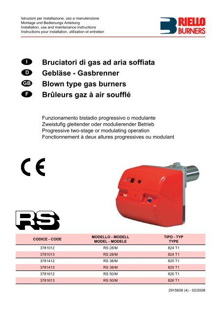
Bruciatori di gas ad aria soffiata Gebläse ... - Riello Burners
Bruciatori di gas ad aria soffiata Gebläse ... - Riello Burners
Bruciatori di gas ad aria soffiata Gebläse ... - Riello Burners
- No tags were found...

You also want an ePaper? Increase the reach of your titles
YUMPU automatically turns print PDFs into web optimized ePapers that Google loves.
D776D778mm A (1) B C kgRS 28/M 872-1007 550 540 38RS 38/M 872-1007 550 540 40RS 50/M 872-1007 550 540 41(B)(A)D777D88DESCRIZIONE BRUCIATORE (A)1 Testa <strong>di</strong> combustione2 Elettrodo d’accensione3 Vite per regolazione testa <strong>di</strong> combustione4 Pressostato <strong>gas</strong> <strong>di</strong> massima5 Pressostato <strong>aria</strong> (tipo <strong>di</strong>fferenziale)6 Sonda per il controllo presenza fiamma7 Presa <strong>di</strong> pressione <strong>aria</strong>8 Presa <strong>di</strong> pressione <strong>gas</strong> e vite fissa testa9 Vite per il fissaggio ventilatore al manicotto10 Guide per apertura bruciatore ed ispezionealla testa <strong>di</strong> combustione11 Servomotore, comanda la farfalla del <strong>gas</strong> e,tramite una camma a profilo v<strong>aria</strong>bile, la serrand<strong>ad</strong>ell’<strong>aria</strong>.Durante la sosta del bruciatore la serrand<strong>ad</strong>ell’<strong>aria</strong> è completamente chiusa per ridurreal minimo le <strong>di</strong>spersioni termiche della caldai<strong>ad</strong>ovute al tiraggio del camino cherichiama l’<strong>aria</strong> dalla bocca <strong>di</strong> aspirazione delventilatore.12 Piastrina pre<strong>di</strong>sposta per ottenere 4 fori, utilial passaggio dei cavi elettrici13 Ingresso <strong>aria</strong> nel ventilatore14 Condotto arrivo <strong>gas</strong>15 Valvola farfalla <strong>gas</strong>16 Flangia per il fissaggio alla caldaia17 Disco <strong>di</strong> stabilità fiamma18 Visore fiamma19 Un interruttore per:funzionamento automatico-manuale-spentoUn pulsante per:aumento - <strong>di</strong>minuzione potenza20 Contattore motore e relè termico con pulsante<strong>di</strong> sblocco (RS 38-50/M)21 Condensatore motore (RS 28/M)22 Apparecchiatura elettrica con avvisatoreluminoso <strong>di</strong> blocco e pulsante <strong>di</strong> sblocco23 Morsettiera per il collegamento elettrico24 Serranda <strong>aria</strong>25 Tubetto che collega l’aspirazione del ventilatoreal pressostato <strong>aria</strong>26 Staffa per l’applicazione del regolatore <strong>di</strong>potenza RWF4027 Spina-presa sul cavo della sonda <strong>di</strong> ionizzazioneVi sono due possibilità <strong>di</strong> blocco del bruciatore:• BLOCCO APPARECCHIATURA:l’accensione del pulsante dell’apparecchiatura22)(A) avverte che il bruciatore è in blocco.Per sbloccare premere il pulsante.• BLOCCO MOTORE (RS 38-50/M):alimentazione elettrica a due fasi, per sbloccarepremere il pulsante del relè termico20)(A).IMBALLO - PESO (B) - misure in<strong>di</strong>cative• I bruciatori vengono spe<strong>di</strong>ti in imballi <strong>di</strong> cartonecon <strong>di</strong>mensioni <strong>di</strong> ingombro secondotab. (B).• Il peso del bruciatore completo <strong>di</strong> imballo èin<strong>di</strong>cato nella tab. (B).INGOMBRO (C) - misure in<strong>di</strong>cativeL'ingombro del bruciatore è riportato in fig.(C).Tener presente che per ispezionare la testa <strong>di</strong>combustione il bruciatore deve essere arretratoe ruotato verso l’alto.L'ingombro del bruciatore aperto, senza cofano,è in<strong>di</strong>cato dalla quota H.(C)mm A B C D (1) E F G H I L MRS 28/M 476 474 580 216-351 140 352 164 810 108 168 1”1/2RS 38/M 476 474 580 216-351 140 352 164 810 108 168 1”1/2RS 50/M 476 474 580 216-351 152 352 164 810 108 168 1”1/2(1) Boccaglio: corto-lungo / Flammenrohr: kurz-lang / Blast tube: short-long / Buse: courte-longueD495CORREDO1 - Flangia per rampa <strong>gas</strong>1 - Guarnizione per flangia4 - Viti per fissare la flangia M 8 x 251 - Schermo termico4 - Viti per fissare la flangia del bruciatore allacaldaia: M 8 x 255 - Passacavi per collegamento elettrico(RS 28/M)6 - Passacavi per collegamento elettrico(RS 38-50/M)1 - Istruzione1 - Catalogo ricambi8
CAM. COMB. / FEUERRAUM mbarCOMB. CHAMBER / CHAMB. COMB.CAMPI DI LAVORO (A)La potenza del bruciatore v<strong>aria</strong> in funzionamentotra:• una POTENZA MASSIMA, scelta entro l’ area A,• e una POTENZA MINIMA, che non deveessere inferiore al limite minimo del <strong>di</strong>agramma:RS 28/M = 52 kWRS 38/M = 70 kWRS 50/M = 85 kWAttenzioneIl CAMPO DI LAVORO è stato ricavato alla temperaturaambiente <strong>di</strong> 20 °C, alla pressione barometrica<strong>di</strong> 1000 mbar (circa 100 m s.l.m.) e conla testa <strong>di</strong> combustione regolata come in<strong>di</strong>cato apagina 16.CALDAIA DI PROVA (B)I campi <strong>di</strong> lavoro sono stati ricavati in specialicaldaie <strong>di</strong> prova, secondo la norma EN 676.Riportiamo in (B) <strong>di</strong>ametro e lunghezza dellacamera <strong>di</strong> combustione <strong>di</strong> prova.EsempioPotenza 350 Mcal/h:<strong>di</strong>ametro 50 cm - lunghezza 1,5 m.CALDAIE COMMERCIALIL’abbinamento bruciatore-caldaia non poneproblemi se la caldaia è omologata CE e le<strong>di</strong>mensioni della sua camera <strong>di</strong> combustionesono vicine a quelle in<strong>di</strong>cate dal <strong>di</strong>agramma (B).Se, invece, il bruciatore deve essere applicato<strong>ad</strong> una caldaia commerciale non omologata CEe/o con <strong>di</strong>mensioni della camera <strong>di</strong> combustionenettamente più piccole <strong>di</strong> quelle in<strong>di</strong>cate dal <strong>di</strong>agramma(B), consultare i costruttori.CAM. COMB. / FEUERRAUM mCOMB. CHAMBER / CHAMB. COMB.CAM. COMB. / FEUERRAUM mbarCOMB. CHAMBER / CHAMB. COMB.CAM. COMB. / FEUERRAUM mbarCOMB. CHAMBER / CHAMB. COMB.(A)D1061D497(B)10
REGELBEREICHE (A)Wahrend des Betriebs schwankt <strong>di</strong>e Brennerleistungzwischen:• einer HÖCHSTLEISTUNG, innerhalb desFeldes A gewählt,• und einer MINDESTLEISTUNG, <strong>di</strong>e nicht niedrigersein darf als <strong>di</strong>e Mindestgrenze desDiagramms.RS 28/M = 52 kWRS 38/M = 70 kWRS 50/M = 85 kWAchtungDer REGELBEREICH wurde bei einerRaumtemperatur von 20 °C, einem barometrischenDruck von 1000 mbar (ungefähr 100 mü.d.M.) und bei wie auf Seite 17 eingestelltemFlammkopf gemessen.PRÜFKESSEL (B)Die Regelbereiche wurden an speziellenPrüfkesseln entsprechend Norm EN 676 ermittelt.In (B) sind Durchmesser und Länge der Prüfbrennkammerangegeben.BeispielLeistung 350 Mcal/h:Durchmesser = 50 cm - Länge = 1,5 m.HANDELSÜBLICHE KESSELDie Brenner-Kessel Kombination gibt keineProbleme, falls der Kessel "CE" - typgeprüft istund <strong>di</strong>e Abmessungen seiner Brennkammersich den im Diagramm (B) angegebenennähern.Falls der Brenner dagegen an einem handelsüblichenKessel angebracht werden muß, dernicht "CE"-typgeprüft ist und/oder mit Abmessungender Brennkammer, <strong>di</strong>e entschiedenkleiner als jene in Diagramm (B) angegebenensind, sollte der Hersteller zu Rate gezogen werden.FIRING RATES (A)During operation, burner output varies between:• a MAXIMUM OUTPUT, selected within area A,• and a MINIMUM OUTPUT, which must not belower than the minimum limit in the <strong>di</strong>agram.RS 28/M = 52 kWRS 38/M = 70 kWRS 50/M = 85 kWImportantThe FIRING RATE area values have beenobtained considering an ambient temperature of20 °C, and an atmospheric pressure of 1000mbar (approx. 100 m above sea level) and withthe combustion he<strong>ad</strong> <strong>ad</strong>justed as shown onpage 17.TEST BOILER (B)The firing rates were set in relation to specialtest boilers, accor<strong>di</strong>ng to EN 676 regulations.Figure (B) in<strong>di</strong>cates the <strong>di</strong>ameter and length ofthe test combustion chamber.ExampleOutput 350 Mcal/h:<strong>di</strong>ameter = 50 cm - length = 1,5.COMMERCIAL BOILERSThe burner/boiler combination does not poseany problems if the boiler is CE type-approvedand its combustion chamber <strong>di</strong>mensions aresimilar to those in<strong>di</strong>cated in <strong>di</strong>agram (B).If the burner must be combined with a commercialboiler that has not been Ce type-approvedand/or its combustion chamber <strong>di</strong>mensions areclearly smaller than those in<strong>di</strong>cated in <strong>di</strong>agram(B), consult the manufacturer.PLAGES DE PUISSANCE (A)La puissance du brûleur en fonctionnementvarie entre:• une PUISSANCE MAXIMUM, choisie dans laplage A,• et une PUISSANCE MINIMUM, qui ne doitpas être inférieure à la limite minimum du <strong>di</strong>agramme.RS 28/M = 52 kWRS 38/M = 70 kWRS 50/M = 85 kWAttentionLa PLAGE DE PUISSANCE a été calculée àune température ambiante de 20 °C, à unepression barométrique de 1000 mbar (environ100 m au-dessus du niveau de la mer) et avecla tête de combustion réglée comme in<strong>di</strong>que lapage 17.CHAUDIERE D’ESSAI (B)Les plages de puissance ont été établies surdes chaiuières d’essai spéciales, selon la normeEN 676.Nous reportons fig.(B) le <strong>di</strong>amètre et la longueurde la chambre de combustion d’essai.ExempePuissance 350 Mcal/h:<strong>di</strong>amètre 50 cm - longueur 1,5 m.CHAUDIERES COMMERCIALESL’accouplement brûleur-chau<strong>di</strong>ère ne poseaucun problème si la chau<strong>di</strong>ère est homologuéeCE et si les <strong>di</strong>mensions de sa chambre de combustionsont proches de celles in<strong>di</strong>quées dansle <strong>di</strong>agramme (B).Par contre, si le brûleur doit être accouplé à unechau<strong>di</strong>ère commerciale non homologuée CE, et/ou avec des <strong>di</strong>mensions de chambre de combustionplus petites que celles in<strong>di</strong>quées dans le<strong>di</strong>agramme (B), consulter le constructeur.11
GASDRUCKIn den nebenstehenden Tabellen werden <strong>di</strong>eMindestströmungsverluste entlang der Gaszuleitungin Abhängigkeit der Höchstleistungdes Brenners angezeigt.Spalte 1Strömungsverlust Flammkopf.Gasdruck am Anschluß 1)(B) gemessen, bei:• Brennkammer auf 0 mbar• Brennerbetrieb auf Höchstleistung• A = Gemäß Diagramm (C)S.16 eingestellterGasscheibe 2)(B)S.16• B = Gasscheibe 2)(B) auf Null eingestellt.Spalte 2Strömungsverlust Gasdrossel 2)(B) bei maximalerÖffnung: 90°.Spalte 3Strömungsverlust Armaturen 3)(B) bestehendaus: Regelventil VR, Sicherheitsventil VS (beidebei maximaler Öffnung), Druckregler R, Filter F.Die Tabellenwerte beziehen sich auf:Erd<strong>gas</strong> G20 - Hu 10 kWh/Nm 3 (8,6 Mcal/Nm 3 )Bei:Erd<strong>gas</strong> G25 - Hu 8,6 kWh/Nm 3 (7,4 Mcal/Nm 3 )<strong>di</strong>e Tabellenwerte mit 1,3 multiplizieren.Zur Ermittlung der ungefähren Brennerleistungim Betrieb auf der Höchstleistung des Brenners:- vom Gasdruck an der Entnahmestelle 1)(B)den Druck in der Brennkammer abziehen.- In der Tabelle des betreffenden Brenners,unter Spalte 1A oder B, den der Subtraktionnächsten Wert ablesen.- Die entsprechende Leistung links ablesen.Beispiel - RS 28/M:• Betrieb auf Höchstleistung• Erd<strong>gas</strong> G20 - Hu 10 kWh/Nm 3• Gemäß Diagramm (C) S.16 eingestellte Gasscheibe2)(B)S.16• Gasdruck an der Entnahmestelle 1)(B) = 6 mbar• Druck in der Brennkammer = 2 mbar6 - 2 = 4 mbarDem Druck von 4 mbar, Spalte 1A, entspricht inder Tabelle RS 28/M eine Leistung von 210 kW.Dieser Wert <strong>di</strong>ent als erste Näherung; der tatsächlicheDurchsatz wird am Zähler abgelesen.Zur Ermittlung des für den an der Entnahmestelle1)(B) erforderlichen Gasdrucks, nachdem<strong>di</strong>e gewünschte Höchstleistung des Brennersfestgelegt wurde:- in der Tabelle des betreffenden Brenners <strong>di</strong>edem gewünschten Wert nächste Leistungsangabeablesen.- Rechts, unter der Spalte 1A oder B, denDruck an der Entnahmestelle 1)(B) ablesen.- Diesen Wert mit dem angenommenen Druckin der Brennkammer <strong>ad</strong><strong>di</strong>eren.Beispiel - RS 28/M:• Gewünschte Höchstleistung: 210 kW• Erd<strong>gas</strong> G20 - Hu 10 kWh/Nm 3• Gemäß Diagramm (C)S.16 eingestellte Gasscheibe2)(B)S.16• Gasdruck bei 210 kW Leistung, aus TabelleRS 28/M, Spalte 1A = 4 mbar• Druck in der Brennkammen = 2 mbar4 + 2 = 6 mbarerforderlicher Druck an der Entnahmestelle1)(B).GAS PRESSUREThe <strong>ad</strong>jacent tables show minimum pressurelosses along the <strong>gas</strong> supply line depen<strong>di</strong>ng onthe maximum burner output operation.Column 1Pressure loss at combustion he<strong>ad</strong>.Gas pressure measured at test point 1)(B), with:• Combustion chamber at 0 mbar• Burner operating at maximum output• A = Gas ring 2)(B)p.16 <strong>ad</strong>justed as in<strong>di</strong>cate<strong>di</strong>n <strong>di</strong>agram (C)p.16• B = Gas ring 2)(B) <strong>ad</strong>justed to zero.Column 2Pressure loss at <strong>gas</strong> butterfly valve 2)(B) withmaximum opening: 90°.Column 3Pressure loss of <strong>gas</strong> train 3)(B) includes: <strong>ad</strong>justmentvalve VR, safety valve VS (both fullyopen), pressure governor R, filter F.The values shown in the various tables refer to:natural <strong>gas</strong> G 20 PCI 10 kWh/Nm 3 (8,6 Mcal/Nm 3 )With:natural <strong>gas</strong> G 25 PCI 8,6 kWh/Nm 3 (7,4 Mcal/Nm 3 )multiply tabulated values by 1,3.Calculate the approximate maximum output ofthe burner thus:- subtract the combustion chamber pressurefrom the <strong>gas</strong> pressure measured at test point1)(B).- Find the nearest pressure value to your resultin column 1A or B of the table for the burner inquestion.- Re<strong>ad</strong> off the correspon<strong>di</strong>ng output on the left.Example - RS 28/M:• Maximum output operation• Natural <strong>gas</strong> G 20 PCI 10 kWh/Nm 3• Gas ring 2)(B)p.16 <strong>ad</strong>justed as in<strong>di</strong>cated in<strong>di</strong>agram (C)p.16• Gas pressure at test point 1)(B) = 6 mbar• Pressure in combustion chamber = 2 mbar6 - 2 = 4 mbarA maximum output of 210 kW shown in TableRS 28/M corresponds to 4 mbar pressure, column1A.This value serves as a rough guide, the effectivedelivery must be measured at the <strong>gas</strong> meter.To calculate the required <strong>gas</strong> pressure at testpoint 1)(B), set the maximim output requiredfrom the burner operation:- find the nearest output value in the table forthe burner in question.- Re<strong>ad</strong> off the pressure at test point 1)(B) onthe right in column 1A or B.- Add this value to the estimated pressure inthe combustion chamber.Example - RS 28/M:• Required burner maximum output operation:210 kW• Natural <strong>gas</strong> G 20 PCI 10 kWh/Nm 3• Gas ring 2)(B)p.16 <strong>ad</strong>justed as <strong>di</strong>agram(C)p.16• Gas pressure at burner output of 210 kW, takenfrom table RS 28/M, column 1A = 4 mbar• Pressure in combustion chamber = 2 mbar4 + 2 = 6 mbarpressure required at test point 1)(B).PRESSION DU GAZLes tableaux ci-contre in<strong>di</strong>quent les pertes decharge minimales sur la ligne d'alimentation engaz en fonction de la puissance maximum dubrûleur.Colonne 1Perte de charge tête de combustion.Pression du gaz mesurée à la prise 1)(B), avec:• Chambre de combustion à 0 mbar• Brûleur fonctionnant à la puissance maximum• A = Bague du gaz 2)(B)p.16 réglée selon le<strong>di</strong>agramme (C)p.16• B = Bague du gaz 2)(B) réglée à zéro.Colonne 2Perte de charge vanne papillon gaz 2)(B) avecouverture maximum: 90°.Colonne 3Perte de charge de la rampe gaz 3)(B) comprenant:vanne de régulation VR, vanne de sûretéVS (ayant chacune une ouverture maximum),régulateur de pression R, filtre F.Les valeurs reportées sur les tableaux seréfèrent à:gaz naturel G 20 PCI 10 kWh/Nm 3 (8,6 Mcal/Nm 3 )Avec:gaz naturel G 25 PCI 8,6 kWh/Nm 3 (7,4 Mcal/Nm 3 )multiplier les valeurs des tableaux par 1,3.Pour connaître la puissance maximum approximativeà laquelle le brûleur fonctionne:- soustraire la pression dans la chambre decombustion de la pression du gaz à la prise1)(B).- Repérer la valeur la plus proche du résultatobtenu sur le tableau relatif au brûleur considéré,colonne 1A ou B.- Lire la puissance correspondante sur lagauche.Exemple - RS 28/M:• Fonctionnement à la puissance maximum• Gaz naturel G 20 PCI 10 kWh/Nm 3• Bague du gaz 2)(B)p.16 réglée selon le <strong>di</strong>agramme(C)p.16• Pression du gaz à la prise 1)(B) = 6 mbar• Pression en chambre de combustion = 2 mbar6 - 2 = 4 mbarSur le tableau RS 28/M à la pression de 4 mbar,colonne 1A, correspond une puissance de 210kW.Cette valeur sert de première approximation; ledébit effectif est mesuré sur le compteur.Par contre, pour connaître la pression du gaznécessaire à la prise 1)(B), après avoir fixé lapuissance maximum de fonctionnement du brûleur:- repérer la puissance la plus proche à lavaleur voulue dans le tableau relatif au brûleurconcerné.- Lire la pression à la prise 1)(B) sur la droite,colonne 1A ou B.- Ajouter à cette valeur la pression estiméedans la chambre de combustion.Exemple - RS 100/M:• Puissance maximum désirée: 210 kW• Gaz naturel G 20 PCI 10 kWh/Nm 3• Bague du gaz 2)(B)p.16 réglée selon le <strong>di</strong>agramme(C)p.16• Pression du gaz à la puissance de 210 kW, surle tableau RS 28/M, column 1A = 4 mbar• Pression dans la chambre de comb.= 2 mbar4 + 2 = 6 mbarpression nécessaire à la prise 1)(B).13
INSTALLAZIONEmm A B CRS 28/MRS 38/MRS 50/M(A)160160160224224224M 8M 8M 8D455PIASTRA CALDAIA (A)Forare la piastra <strong>di</strong> chiusura della camera <strong>di</strong>combustione come in (A). La posizione dei forifilettati può essere tracciata utilizzando loschermo termico a corredo del bruciatore.LUNGHEZZA BOCCAGLIO (B)La lunghezza del boccaglio va scelta secondo lein<strong>di</strong>cazioni del costruttore della caldaia e, in ognicaso, deve essere maggiore dello spessoredella porta della caldaia, completa <strong>di</strong> refrattario.Le lunghezze, L (mm), <strong>di</strong>sponibili sono:Boccaglio 10) RS 28/M RS 38/M RS 50/M• corto 216 216 216• lungo 351 351 351Per le caldaie con giro dei fumi anteriore 13), ocon camera <strong>ad</strong> inversione <strong>di</strong> fiamma, eseguireuna protezione in materiale refrattario 11), trarefrattario caldaia 12) e boccaglio 10).La protezione deve consentire al boccaglio <strong>di</strong>essere estratto.Per le caldaie con il frontale raffreddato <strong>ad</strong>acqua non è necessario il rivestimento refrattario11)-12)(B), se non vi è espressa richiesta delcostruttore della caldaia.(B)D779FISSAGGIO DEL BRUCIATORE ALLA CAL-DAIA (B)Prima <strong>di</strong> fissare il bruciatore alla caldaia, verificaredall’apertura del boccaglio se la sonda el’elettrodo sono correttamente posizionati comein (C).Separare quin<strong>di</strong> la testa <strong>di</strong> combustione dalresto del bruciatore, fig. (B):- togliere la vite 14) ed estrarre il cofano 15);- sganciare lo snodo 4) dal settore gr<strong>ad</strong>uato 5);- togliere le viti 2) dalle due guide 3);- togliere la vite 1) ed arretrare il bruciatore sulleguide 3) per circa 100 mm;- <strong>di</strong>sinserire i cavi <strong>di</strong> sonda ed elettrodo e quin<strong>di</strong>sfilare del tutto il bruciatore dalle guide, dopoaver tolto la copiglia dalla guida 3).Fissare la flangia 9)(B) alla piastra della caldaiainterponendo lo schermo isolante 6)(B) dato acorredo. Utilizzare le 4 viti pure date a corredodopo averne protetto la filettatura con prodottiantigrippanti.La tenuta bruciatore-caldaia deve essere ermetica.Se nel controllo precedente il posizionamentodella sonda o dell’elettrodo non è risultato corretto,togliere la vite 1)(D), estrarre la parteinterna 2)(D) della testa e provvedere alla lorotaratura.Non ruotare la sonda ma lasciarla come in (C);un suo posizionamento vicino all’elettrodod’accensione potrebbe danneggiare l’amplificatoredell’apparecchiatura.SONDAFÜHLERPROBESONDEELETTRODO RS 28-38/MELEKTRODE RS 28-38/MELECTRODE RS 28-38/MELECTRODE RS 28-38/MELETTRODO RS 50/MELEKTRODE RS 50/MELECTRODE RS 50/MELECTRODE RS 50/M(C)D880D501(D)14
INSTALLATIONKESSELPLATTE (A)Die Abdeckplatte der Brennkammer wie in (A)gezeigt vorbohren. Die Position der Gewindebohrungenkann mit der zur Grundausstattunggehörenden Wärmeschild ermittelt werden.FLAMMROHRLÄNGE (B)Die Länge des Flammrohrs wird entsprechendder Angaben des Kesselherstellers gewählt undmuß in jedem Fall größer als <strong>di</strong>e Stärke der Kesseltüreinschließlich feuerfestes Material sein.Die verfügbaren Längen, L (mm), sind:Flammrohr 10) RS 28/M RS 38/M RS 50/M• kurz 216 216 216• lang 351 351 351Für Heizkessel mit vorderem Ab<strong>gas</strong>umlauf 13)oder Flammenumkehrkammer muß eine Schutzschichtaus feuerfestem Material 11), zwischenfeuerfestem Material 12) und Flammrohr 10)ausgefüht werden.Diese Schutzschicht muß so angelegt sein, daßdas Flammrohr ausbaubar ist.Für <strong>di</strong>e Kessel mit wassergekühlter Frontseiteist <strong>di</strong>e Verkleidung mit feuerfestem Material 11)-12)(B) nicht notwen<strong>di</strong>g, sofern nicht ausdrücklichvom Kesselhersteller erfordert.BEFESTIGUNG DES BRENNERS AM HEIZ-KESSEL (B)Vor der Befestigung des Brenners am Heizkesselist von der Öffnung des Flammrohrs aus zuüberprüfen, ob der Fühler und <strong>di</strong>e Elektrodegemäß (C) in der richtigen Stellung sind.Dann den Flammkopf vom übrigen Brennertrennen, Abb. (B):- Schraube 14) abnehmen und <strong>di</strong>e Verkleidung15) herausziehen;- das Gelenk 4) des Skalensegments 5) ausrasten;- <strong>di</strong>e Schrauben 2) von den zwei Führungen 3)abnehmen;- <strong>di</strong>e Schrauben 1) abnehmen und den Brennerauf den Führungen 3) ca. 100 mm. nachhinten ziehen;- <strong>di</strong>e Fuhler- und Elektrodenkabel abtrennenund dann den Brenner komplett aus denFührungen ziehen, nach Entnahme des Splintaus der Führung 3).Den Flansch 9)(B) an der Kesseltür befestigenund den beigestellten Wärmeschild 6)(B)dazwischenlegen. Die 4 ebenfalls beigepacktenSchrauben nach Auftragung von Freßschutzmittelnverwenden.Es muß <strong>di</strong>e Dichtheit von Brenner-Kesselgewährleistet sein.Hat <strong>di</strong>e vorausgehende Positionsprüfung vonFühler oder Elektrode einen Fehler ergeben, <strong>di</strong>eSchraube 1)(D) abnehmen, das Innenteil 2)(D)des Kopfs herausziehen und eine neue Einstellungvornehmen.Den Fühler nicht drehen, sondern wie in (C) lassen;seine Positionierung in der Nähe der Zündelektrodekönnte den Geräteverstärkerbeschä<strong>di</strong>gen.INSTALLATIONBOILER PLATE (A)Drill the combustion chamber locking plate asshown in (A). The position of the thre<strong>ad</strong>ed holescan be marked using the thermal screen suppliedwith the burner.BLAST TUBE LENGTH (B)The length of the blast tube must be selectedaccor<strong>di</strong>ng to the in<strong>di</strong>cations provided by themanufacturer of the boiler, and in any case itmust be greater than the thickness of the boilerdoor complete with its fettling. The range oflengths available, L (mm), is as follows:Blast tube 10) RS 28/M RS 38/M RS 50/M• short 216 216 216• long 351 351 351For boilers with front flue passes 13) or flameinversion chambers, protective fettling in refractorymaterial 11), must be inserted between theboiler fettling 12) and the blast tube 10).This protective fettling must not compromise theextraction of the blast tube.For boilers having a water-cooled front therefractory fettling 11)-12)(B) is not requiredunless it is expressly requested by the boilermanufacturer.SECURING THE BURNER TO THE BOILER(B)Before securing the burner to the boiler, checkthrough the blast tube opening to make surethat the flame sensor probe and the ignitionelectrode are correctly set in position, as shownin (C).Now detach the combustion he<strong>ad</strong> from theburner, fig. (B):- remove screw 14) and withdraw the cover 15);- <strong>di</strong>sengage the articulated coupling 4) from thegr<strong>ad</strong>uated sector 5);- remove the screws 2) from the two slide bars3);- remove screw 1) and pull the burner back onslide bars 3) by about 100 mm;- <strong>di</strong>sconnect the wires from the probe and theelectrode and then pull the burner completelyoff the slide bars, after removing the split pinfrom the slide bar 3).Secure the flange 9)(B) to the boiler plate, interposingthe thermal insulating screen 6)(B) suppliedwith the burner. Use the 4 screws, alsosupplied with the unit, after first protecting thethre<strong>ad</strong> with an anti-locking product.The seal between burner and boiler must be airtight.If any irregularities in positions of the probe orignition electrode during the check mentionedabove, remove screw 1)(D), extract the internalpart 2)(D) of the he<strong>ad</strong> and proceed to set up thetwo components correctly.Do not attempt to turn the probe. Leave it in theposition shown in (C) since if it is located tooclose to the ignition electrode the control boxamplifier may be damaged.INSTALLATIONPLAQUE CHAUDIERE (A)Percer la plaque de fermeture de la chambre decombustion comme sur la fig. (A). La positiondes trous filetés peut être tracée en utilisantl'écran thermique fourni avec le brûleur.LONGUEUR BUSE (B)La longueur de la buse doit être choisie selonles in<strong>di</strong>cations du constructeur de la chau<strong>di</strong>ère,et tout cas, elle doit en être supérieure à l'épaisseurde la porte de la chau<strong>di</strong>ère, matériauréfractaire compris. Les longueurs, L (mm), <strong>di</strong>sponiblesont:Buse 10) RS 28/M RS 38/M RS 50/M• courte 216 216 216• longue 351 351 351Pour les chau<strong>di</strong>ères avec circulation desfumées sur l'avant 13), ou avec chambre àinversion de flamme, réaliser une protection enmatériau réfractaire 11), entre réfractairechau<strong>di</strong>ère 12) et buse 10).La protection doit permettre l'extraction de labuse.Pour les chau<strong>di</strong>ères dont la partie frontale estrefroi<strong>di</strong>e par eau, le revêtement réfractaire 11)-12)(B) n'est pas nécessaire, sauf in<strong>di</strong>cationexpresse du constructeur de la chau<strong>di</strong>ère.FIXATION DU BRULEUR A LA CHAUDIERE(B)Avant de fixer le brûleur à la chau<strong>di</strong>ère, vérifierpar l'ouverture de la buse si la sonde et l'électrodesont positionnées correctement commein<strong>di</strong>qué en (C).Séparer ensuite la tête de combustion du restedu brûleur, fig. (B):- retirer la vis 14) et extraire le coffret 15);- décrocher la rotule 4) du secteur gr<strong>ad</strong>ué 5);- retirer les vis 2) des deux guides 3);- retirer la vis 1) et faire reculer le brûleur sur lesguides 3) d'environ 100 mm;- détacher les câbles de la sonde et de l'électrode,enlever ensuite complètement le brûleurdes guides, après avoir ôté la goupille de laguide 3).Fixer la bride 9)(B) à la plaque de la chau<strong>di</strong>èreen interposant l'écran isolant 6)(B) fourni desérie. Utiliser les 4 vis également de série aprèsen avoir protégé le filetage par du produit antigrippant.L'étanchéité brûleur-chau<strong>di</strong>ère doit être parfaite.Si, lors du contrôle précédent, le positionnementde la sonde ou de l'électrode n'était pas correct,retirer la vis 1)(D), extraire la partie interne 2)(D)de la tête et tarer celles-ci. Ne pas faire pivoterla sonde mais la laisser en place commein<strong>di</strong>qué en (C); son positionnement dans le voisinagede l'électrode d'allumage pourrait endommagerl'amplificateur de l'appareil.15
REGOLAZIONE TESTA DI COMBUS-TIONEA questo punto dell’installazione, boccaglio emanicotto sono fissati alla caldaia come in fig.(A). Sono quin<strong>di</strong> particolarmente agevoli leregolazioni delle testa <strong>di</strong> combustione: <strong>aria</strong> e<strong>gas</strong>.Sono possibili due casi:D503(C)(D)(A)N° Tacche (<strong>aria</strong>=<strong>gas</strong>) / Kerben (Luft=Gas) / Notches (Air=Gas) / Encoches (Air=Gaz)POTENZE MINIME DI MODULAZIONE: quando la potenza MIN è compresa entro i valorisotto riportati, la ghiera 2)(B) va regolata a 0.MINDESTLEISTUNGEN DER MODULATION: wenn <strong>di</strong>e Mindestleistung ist innerhalb derunten angeführten Werte beinhalten, ist <strong>di</strong>e Scheibe 2)(B) auf Null einzustellen.MODULATION MINIMUM OUTPUT: when the MIN output is within the value range givenbelow, the <strong>gas</strong> ring 2)(B) is <strong>ad</strong>justed to zero.PUISSANCE MINIMUM DE MODULATION: quand la puissance MIN est comprise dansle valeurs reportées ci-dessous, la bride 2)(B) doit être réglée à 0.RS 28/M 52 ÷ 74 kWRS 38/M 70 ÷ 99 kWRS 50/M 85 ÷ 129 kW(E)D502(B)Potenza Max bruciatoreHöchstbrennerleistungburner Max outputPuissance Max brûleurD780A - La potenza MIN del bruciatore non ècompresa nei valori della tabella (D).Trovare nel <strong>di</strong>agramma (C), in funzione dellapotenza MAX, la tacca alla quale regolare sia<strong>aria</strong> che <strong>gas</strong>, quin<strong>di</strong>:Regolazione <strong>aria</strong> (A)Ruotare la vite 4)(A) fino a far collimare la taccatrovata con il piano anteriore 5)(A) della flangia.Regolazione <strong>gas</strong> (B)Allentare la vite 1)(B) e ruotare la ghiera 2) finoa far collimare la tacca trovata con l’in<strong>di</strong>ce 3).Bloccare la vite 1).Esempio:il bruciatore RS 38/M v<strong>aria</strong> la potenza tra MIN =100 e MAX = 340 kW.La potenza MIN 100 kW non è compresa neivalori della tabella (D) e quin<strong>di</strong> vale il <strong>di</strong>agramma(C), dal quale risulta che per la potenzaMAX <strong>di</strong> 340 kW le regolazioni del <strong>gas</strong> e dell’<strong>aria</strong>vanno effettuate sulla tacca 3, come in fig. (A) e(B). In questo caso la per<strong>di</strong>ta <strong>di</strong> pressione dellatesta <strong>di</strong> combustione è data dalla colonna 1A <strong>di</strong>pag. 12.NOTAIl <strong>di</strong>agramma (C) in<strong>di</strong>ca la regolazione ottimaledella ghiera 2)(B). Se la pressione nella rete <strong>di</strong>alimentazione del <strong>gas</strong> è molto bassa e non consenteil raggiungimento della pressione in<strong>di</strong>cataa pag. 12 alla potenza MAX, e se la ghiera 2)(B)è solo parzialmente aperta, è possibile aprireulteriormente la ghiera <strong>di</strong> 1-2 tacche.Continuando l’esempio precedente, a pag. 12 sivede che per un bruciatore RS 38/M conpotenza <strong>di</strong> 340 kW occorrono 4,6 mbar circa <strong>di</strong>pressione alla presa 6)(A). Se questa pressionenon è <strong>di</strong>sponibile, aprire la ghiera 2)(B) a 4-5tacche.Controllare che la combustione sia sod<strong>di</strong>sfacentee priva <strong>di</strong> pulsazioni.B - La potenza MIN del bruciatore è compresanei valori della tabella (D).Regolazione <strong>aria</strong>Vale quanto detto per il caso precedente: seguireil <strong>di</strong>agramma (C).Regolazione <strong>gas</strong>La ghiera 2)(B) va regolata sempre nellaposizione 0, in<strong>di</strong>pendentemente dalla potenzaMAX del bruciatore.In questo caso la per<strong>di</strong>ta <strong>di</strong> pressione della testa <strong>di</strong>combustione è data dalla colonna 1B <strong>di</strong> pag. 12.Terminata la regolazione della testa, rimontare ilbruciatore 4)(E) sulle guide 3) a circa 100 mmdal manicotto 5) - bruciatore nella posizioneillustrata dalla fig.(B)p.14 - inserire il cavo dellasonda ed il cavo dell’elettrodo e quin<strong>di</strong> far scorrereil bruciatore fino al manicotto, bruciatorenella posizione illustrata dalla fig. (E). Rimetterele viti 2) sulle guide 3).Fissare il bruciatore al manicotto con la vite 1) erimettere la copiglia in una delle due guide 3).Riagganciare lo snodo 8) al settore gr<strong>ad</strong>uato 7).AttenzioneAll’atto della chiusura del bruciatore sulle dueguide, è opportuno tirare delicatamente versol’esterno il cavo d’alta tensione ed il cavettodella sonda <strong>di</strong> rivelazione fiamma, fino a metterliin leggera tensione.16
EINSTELLUNG DES FLAMMKOPFSAn <strong>di</strong>eser Stelle der Installation sind Flammrohrund Muffe gem. Abb. (A) am Kessel befestigt.Die Einstellungen des Flammkopfs ist daherbesonders bequem: <strong>di</strong>e Lufteinstellung und <strong>di</strong>eGaseinstellung.Zwei Fälle sind möglich:A - Die Mindestleistung des Brenners istnicht in den Werten der Tabelle (D) eingeschloßen.In Diagramm (C), in Abhängigkeit der Höchstbrennerleistung,<strong>di</strong>e Kerbe ausfin<strong>di</strong>ng machen,auf <strong>di</strong>e Luft und Gas einzustellen sind, dann:Lufteinstellung (A)Die Schraube 4)(A) drehen, bis <strong>di</strong>e gefundeneKerbe mit der Vorderfläche 5)(A) des Flanscheszusammenfällt.Gaseinstellung (B)Die Schraube 1)(B) lockern und <strong>di</strong>e Scheibe 2)soweit drehen, bis <strong>di</strong>e gefundene Kerbe mit demIndexstift 3) zusammenfällt.Die Schraube 1) blockieren.Beispiel:der Brenner RS 38/M ändert <strong>di</strong>e Leistungzwischen MIN = 100 und MAX = 340 kW.Die Mindestleistung von 100 kW ist nicht in denWerten der Tabelle (D) eingeschloßen, unddaher gilt das Diagramm (C), aus dem es sichergibt, daß für <strong>di</strong>e Höchstleistung von 340 kW<strong>di</strong>e Gas- und Lufteinstellungen auf Kerbe 3 auszuführensind, wie in Abb. (A) und (B) dargestellt.In <strong>di</strong>esem Fall ist der Druckverluft des Flammkopfsin der Spalte 1A auf Seite 12 angegeben.MERKEDas Diagramm (C) zeigt <strong>di</strong>e optimale Einstellungder Scheibe 2)(B). Falls der Gaszuleistungsdruckbesonders niedrig ist und d<strong>ad</strong>urchder auf Seite 12 angegebene Druck in derHöchstleistung nicht erreicht werden kann, undfalls <strong>di</strong>e Scheibe 2)(B) nur teilweise geöffnet ist,kann <strong>di</strong>e letztere um weitere 1-2 Kerben geöffnetwerden.Entsprechend <strong>di</strong>esem Beispiel ist auf Seite 12ersichtlich, daß ein Brenner RS 38/M mit 340kW Leistung ca. 4,6 mbar Druck an derEntnahmestelle 6)(A) erfordert. Liegt <strong>di</strong>eserDruck nicht an, <strong>di</strong>e Scheibe 2)(B) auf <strong>di</strong>e 4-5Kerbe öffnen.Die Verbrennung muß zufriedenstellend undohne Verpuffungen erfolgen.B - Die Mindestleistung des Brenners ist inden Werten der Tabelle (D) eingeschloßen.LufteinstellungEs gilt das gleiche wie im vorhergehenden Fall:dem Diagramm (C) folgen.GaseinstellungDie Scheibe 2)(B) ist immer auf Null einzustellen,unabhängigkeit von der Höchstleistung desBrenners.In <strong>di</strong>esem Fall ist der Druckverlust des Flammkopfsunter Spalte 1B auf Seite 12 angegeben.Nach Beendung der Flammkopfeinstellung denBrenner 4)(E) auf <strong>di</strong>e Führungen 3) in ca. 100mm Abstand zum Brennerkopf 5) - einbauen -Brennerposition in Abb. (B)S.14 - das FühlerundElektrodenkabel einsetzen undanschließend den Brenner bis zur Muffe schieben,Brennerposition in Abb. (E).Die Schrauben 2) auf <strong>di</strong>e Führungen 3) einsetzen.Den Brenner mit der Schraube 1) an der Muffebefestigen und den Splint in eine der zweiFührungen 3) wieder einsetzen.Das Gelenk 8) wieder am Skalensegment 7)einhängen.Wichtiger HinweisBeim Schließen des Brenners ist es ratsam, dasHochspannungskabel und das Kabel des Flammenfühlersvorsichtig nach außen zu ziehen, bissie leicht gespannt sind.SETTING THE COMBUSTION HEADInstallation operations are now at the stagewhere the blast tube and sleeve are secured tothe boiler as shown in fig. (A). Therefore it isparticulary easy to carry out the combustionhe<strong>ad</strong> <strong>ad</strong>justments: air and <strong>gas</strong>.There are two possible cases:A - The MIN burner output is not in the valuesof table (D).In <strong>di</strong>agram (C), depen<strong>di</strong>ng on the MAX output,find the notch to use for <strong>ad</strong>justing the air and the<strong>gas</strong>, and then proceed as follows:Air <strong>ad</strong>justment (A)Turn screw 4)(A) until the notch identified isaligned with the front surface 5)(A) of the flange.Gas <strong>ad</strong>justment (B)Loosen screw 1)(B) and turn ring 2) until thenotch identified is aligned with index 3).Tighten the screw 1) fully down.Example:the burner RS 38/M varies its output between:MIN = 100 e MAX = 340 kW.The MIN output of 100 kW is not found in thevalues of table (D) and therefore <strong>di</strong>agramm (C)is valid, from which it results that for a MAX outputof 340 kW the <strong>gas</strong> and air <strong>ad</strong>justments aredone on notch 3, as in fig. (A) and (B).In this case the pressure lo<strong>ad</strong> loss of the combustionhe<strong>ad</strong> is given by column 1A page 12.NOTEDiagramm (C) shows the ideal settings for thering 2)(B). If the <strong>gas</strong> mains pressure is too lowto reach the max output operation pressure in<strong>di</strong>catedon page 12, and if the ring 2)(B) is not fullyopen, it can be opened wider by 1 or 2 notches.Continuing with the previous example, page 12in<strong>di</strong>cates that for burner RS 38/M with output of340 kW a pressure of approximately 4,6 mbar isnecessary at test point 6)(A). If this pressurecannot be reached, open the ring 2)(B) to notch4 or 5.Make sure that the combustion characteristicsare satisfactory and free of pulsations.B - The MIN burner output is found in thevalues of the table (D).Air <strong>ad</strong>justmentThe same as the previous case: follow <strong>di</strong>agramm(C).Gas <strong>ad</strong>justmentThe <strong>gas</strong> ring 2)(B) is always <strong>ad</strong>justed to position0, irrespective of the MAX burner.In this case the pressure lo<strong>ad</strong> loss of the combustionhe<strong>ad</strong>s is given by column 1B page 12.Once you have finished setting up the he<strong>ad</strong>, refitthe burner 4)(E) to the slide bars 3) at approximately100 mm from the sleeve 5) - burner positionedas shown in fig. (B)p.14 - insert the flamedetection probe cable and the ignition electrodecable and then slide the burner up to the sleeveso that it is positioned as shown in fig. (E).Refit screws 2) on slide bars 3).Secure the burner to the sleeve by tighteningscrew 1) and then refit the split pin into one oftwo slide bars 3).Reconnect the articulation 8) to the gr<strong>ad</strong>uatedsector 7).ImportantWhen fitting the burner on the two slide bars, itis <strong>ad</strong>visable to gently draw out the high tensioncable and flame detection probe cable until theyare slightly stretched.REGLAGE TETE DE COMBUSTIONA ce st<strong>ad</strong>e de l'installation, buse et manchonsont fixés à la chau<strong>di</strong>ère comme in<strong>di</strong>qué sur lafig. (A). Le réglage de la tête de combustion:air et gaz est donc facilité au maximum.Il y a deux cas possibles:A - La puissance MIN du brûleur n’est pascomprise dans les valeurs du tableau (D).Trouver sur le <strong>di</strong>agramme (C), en fonction de lapuissance MAX, l’encoche sur laquelle réglerl’air et le gaz.Réglage de l'air (A)Faire pivoter la vis 4)(A) jusqu'à faire correspondrel'encoche trouvée avec le plan antérieur5)(A) de la bride.Réglage du gaz (B)Desserrer la vis 1)(B) et faire tourner la bague 2)jusqu’à faire correspondre l’encoche avec lerepère 3).Bloquer les vis 1).Exemple:le brûleur RS 38/M varie la puissance entre:MIN = 100 e MAX = 340 kW.La puissance MIN 100 kW n’est pas comprisedans les valeurs du tableau (D), le <strong>di</strong>agramme(C), à partir duquel il résulte que pour la puissanceMAX de 340 kW les réglages du gaz etde l’air doivent être effectués sur l’encoche 3,comme in<strong>di</strong>qué sur les fig. (A) et (B), est doncvalable.Dans ce cas, la perte de pression de la tête decombustion est donnée par la colonne 1A à lapage 12.NOTELe <strong>di</strong>agramme (C) in<strong>di</strong>que le réglage optimal dela bague 2)(B). Si la pression du réseau d’alimentationen gaz est très faible et ne permetpas d’atteindre la pression in<strong>di</strong>quée page 12 à lapuissance maximum, et si la bague 2)(B) n’estouverte qu’en partie, il est possible d’ouvirencore cette bague de 1 ou 2 encoches.Pour continuer l'exemple précédent, la page 12in<strong>di</strong>que que pour un brûleur RS 38/M ayant unepuissance de 340 kW il faut 4,6 mbar environ depression à la prise 6)(A). Si cette pression n’estpas <strong>di</strong>sponible, ouvrir la bague 2)(B) de 4 ou 5encoches.Contrôler que la combustion soit satisfaisante etsans sacc<strong>ad</strong>es.B - La puissance MIN du brûleur est comprisedans les valeurs du tableau (D).Réglage de l’airMême chose que pour le cas précédent: suivrele <strong>di</strong>agramme (C).Réglage du gazLa bague 2)(B) doit toujours être réglée en position0, indépendamment de la puissance MAXdu brûleur.Dans ce cas, la perte de pression de la tête decombustionest donnée par la colonne 1B à lapage 12.Une fois terminé le réglage de la tête, remonterle brûleur 4)(E) sur les guides 3) à environ 100mm du manchon 5) - brûleur dans la positionillustrée fig. (B)p.14 - placer les câbles de lasonde et de l'électrode et ensuite faire coulisserle brûleur jusqu'au manchon, brûleur dans laposition illustrée fig. (E).Replacer les vis 2) sur les guides 3).Fixer le brûleur au manchon avec la vis 1) et remplacerla goupille dans un des deux guides 3).Raccrocher la rotule 8) au secteur gr<strong>ad</strong>ué 7).AttentionAu moment de la fermeture du brûleur sur lesdeux guides, il faut tirer délicatement versl'extérieur le câble de haute tension et le petitcâble de la sonde de détection flamme, jusqu'àce qu'ils soient légèrement tendus.17
(A)(B)BRUCIATORI E RELATIVE RAMPE GAS OMOLOGATE SECONDO NORMA EN 676GASBRENNER UND ZUGEHÖRIGE NACH EN 676 TYPGEPRÜFTE GASARMATURENGAS BURNERS AND RELEVANT GAS TRAINS APPROVED ACCORDING TO EN 676BRULEURS ET RELATIVES RAMPES GAZ HOMOLOGUEES SELON LA NORME EN 676RAMPE - GASARMATURENGAS TRAINS - RAMPE GAZ L(C)BRUCIATORE - BRENNERBURNER - BRULEUR13 14Ø C.T. Code RS 28/M RS 38/M RS 50/M Code Code3/4” - 3970076 • - - 3010123 30008241” - 3970077 • • • 3010123 30008241”1/4 - 3970144 • • • 3010123 -1”1/2 - 3970145 • • • 3010123 -1”1/2 - 3970180 • • • 3010123 -2”2”2”2”-♦-♦3970146397016039701813970182COMPONENTI RAMPA GAS - BESTANDTEILE GASARMATURENGAS TRAINS COMPONENTS - COMPOSANTS RAMPE GAZ----••••••••3010123-3010123-3000822300082230008223000822COMPONENTI - BESTANDTEILECOD.COMPONENTS - COMPOSANTS5 6 8 - 93970076 Multiblock MB DLE 4073970077 Multiblock MB DLE 4103970144 Multiblock MB DLE 4123970145 GF 515/1 FRS 515 DMV DLE 512/113970180 Multiblock MB DLE 41539701463970160GF 520/1 FRS 520 DMV DLE 520/1139701813970182Multiblock MB DLE 420D505D1062LINEA ALIMENTAZIONE GAS• La rampa del <strong>gas</strong> va collegata all’attacco del<strong>gas</strong> 1)(A), tramite la flangia 2), la guarnizione3) e le viti 4) date a corredo del bruciatore.• La rampa può arrivare da destra o da sinistra,secondo como<strong>di</strong>tà, ve<strong>di</strong> fig. (A).• Le elettrovalvole 8)-9)(B) del <strong>gas</strong> devonoessere il più vicino possibile al bruciatore inmodo da assicurare l'arrivo del <strong>gas</strong> alla testa<strong>di</strong> combustione nel tempo <strong>di</strong> sicurezza <strong>di</strong> 2 s.• Assicurarsi che il campo <strong>di</strong> taratura del regolatore<strong>di</strong> pressione (colore della molla) comprendala pressione necess<strong>aria</strong> al bruciatore.RAMPA GAS (B)E' omologata secondo norma EN 676 e vienefornita separatamente dal bruciatore con ilco<strong>di</strong>ce in<strong>di</strong>cato in tab. (C).LEGENDA (B)1 - Condotto arrivo del <strong>gas</strong>2 - Valvola manuale3 - Giunto antivibrante4 - Manometro con rubinetto a pulsante5 - Filtro6 - Regolatore <strong>di</strong> pressione (verticale)7 - Pressostato <strong>gas</strong> <strong>di</strong> minima8 - Elettrovalvola <strong>di</strong> sicurezza VS (verticale)9 - Elettrovalvola <strong>di</strong> regolazione VR (verticale)Due regolazioni:• portata d'accensione (apertura rapida)• portata massima (apertura lenta)10 - Guarnizione e flangia a corredo bruciatore11 - Farfalla regolazione <strong>gas</strong>12 - Bruciatore13 - Dispositivo <strong>di</strong> controllo tenuta valvole 8)-9).Secondo la norma EN 676 il controllo <strong>di</strong>tenuta è obbligatorio per i bruciatori conpotenza massima superiore a 1200 kW.14 - Adattatore rampa-bruciatore15 - Pressostato <strong>gas</strong> <strong>di</strong> massimaP1 - Pressione alla testa <strong>di</strong> combustioneP2 - Pressione a valle del regolatoreP3 - Pressione a monte del filtroL - Rampa <strong>gas</strong> fornita a parte con il co<strong>di</strong>cein<strong>di</strong>cato in tab. (C).L1 - A cura dell'installatoreLEGENDA TABELLA (C)C.T.= Dispositivo controllo tenuta valvole <strong>gas</strong>8) - 9):- = Rampa priva del <strong>di</strong>spositivo <strong>di</strong> controllotenuta; <strong>di</strong>spositivo che puòessere or<strong>di</strong>nato a parte, ve<strong>di</strong> colonna13, e montato successivamente.♦= Rampa con il <strong>di</strong>spositivo <strong>di</strong> controllotenuta VPS montato.13 = Dispositivo <strong>di</strong> controllo tenuta valvoleVPS.Fornito su richiesta separatamente dallarampa <strong>gas</strong>.14 = Adattatore rampa-bruciatore.Fornito su richiesta separatamente dallarampa <strong>gas</strong>.NotaPer la regolazione della rampa <strong>gas</strong> vedere leistruzioni che l'accompagnano.18
GASZULEITUNG• Gasarmaturen sind über Flansch 2), Dichtung3) und Schrauben 4), zur Brennerausstattunggehörend, mit dem Gasanschluß 1)(A) zuverbinden.• Die Armatur kann je nach Bedarf von rechtsbzw. links zugeführt werden, s. Abb. (A).• Die Gasmagnetventile 8)-9)(B) der Gaszuleistungsollen so nah wie möglich am Brenner liegen,damit <strong>di</strong>e Gaszufuhr zum Flammkopfinnerhalb 2 Sekunden sichergestellt ist.• Überprüfen, ob der Einstellbereich des Druckreglers(Farbe der Feder) <strong>di</strong>e für den Brennererforderlichen Druckwerte vorsieht.GASARMATUREN (B)Nach Norm EN 676 typgeprüft, wird gesondertmit dem in Tab. (C) angegebenen Codegeliefert.ZEICHENERKLÄRUNG (B)1 - Gaszuleitung2 - Handbetätigtes Ventil3 - Kompensator4 - Manometer mit Druckknopfhahn5 - Filter6 - Druckregler (senkrecht)7 - Gas-Minimaldruckwächter8 - Sicherheitsmagnetventil VS (senkrecht)9 - Regelmagnetventil VR (senkrecht)Zwei Einstellungen:• Zünddurchsatz (schnellöffnend)• Max. Durchsatz (langsamöffnend)10 - Dichtung und Flansch Brennergrundausstattung11 - Gas-Einstelldrossel12 - Brenner13 - Dichtheitskontrolleinrichtung der Gasventile8)-9). Laut Norm EN 676 ist <strong>di</strong>e Dichtheitskontrollefür Brenner mitHöchstleistung über 1200 kW Pflicht.14 - Passtück Armatur-Brenner15 - Gas-HöchstdruckwächterP1 - Druck am FlammkopfP2 - Druck nach dem ReglerP3 - Druck vor dem FilterL - Gasarmatur gesondert mit dem in Tab. (C)angegebenen Code geliefert.L1 - Vom Installateur auszuführenZEICHENERKLÄRUNG TABELLE (C)C.T.= Dichtheitskontrolleinrichtung der Gasventile8) - 9):- = Gasarmatur ohne Dichtheitskontrolleinrichtung;<strong>di</strong>e Einrichtung kanngesondert bestellt, siehe Spalte 13,und später eingebaut werden.♦= Gasarmatur mit der eingebautenDichtheitskontrolleinrichtung VPS.13 = Dichtheitskontrolleinrichtung VPS derGasventile.Auf Anfrage gesondert von der Gasarmaturlieferbar.14 = Passtück Armatur-Brenner.Auf Anfrage gesondert von der Gasarmaturlieferbar.MerkeZur Einstellung der Gasarmaturen siehe <strong>di</strong>ebeigelegten Anleitungen.GAS LINE• The <strong>gas</strong> train must be connected to the <strong>gas</strong>attachment 1)(A), using flange 2), <strong>gas</strong>ket 3)and screws 4) supplied with the burner.• The <strong>gas</strong> train can enter the burner from theright or left side, depen<strong>di</strong>ng on which is themost convenient, see fig. (A).• The <strong>gas</strong> solenoids 8)-9)(A) must be as closeas possible to the burner to ensure <strong>gas</strong>reaches the combustion he<strong>ad</strong> within the safetytime range of 2 s.• Make sure that the pressure governor calibrationrange (colour of the spring) comprises thepressure required by the burner.GAS TRAIN (A)It is type-approved accor<strong>di</strong>ng to EN 676 Standardsand is supplied separately from the burnerwith the code in<strong>di</strong>cated in Table (C).KEY (A)1 - Gas input pipe2 - Manual valve3 - Vibration damping joint4 - Pressure gauge with pushbutton cock5 - Filter6 - Pressure governor (vertical)7 - Minimum <strong>gas</strong> pressure switch8 - Safety solenoid VS (vertical)9 - Adjustment solenoid VR (vertical)Two <strong>ad</strong>justments:• ignition delivery (rapid opening)• maximum delivery (slow opening)10 - Standard issue burner <strong>gas</strong>ket with flange11 - Gas <strong>ad</strong>justment butterfly valve12 - Burner13 - Gas valve 8)-9) leak detection controldevice.In accordance with EN 676 Standards, <strong>gas</strong>valve leak detection control devices arecompulsory for burners with maximum outputsof more than 1200 kW.14 - Gas train/burner <strong>ad</strong>aptor15 - Maximum <strong>gas</strong> pressure switchP1 - Pressure at combustion he<strong>ad</strong>P2 - Pressure down-line from the pressure governorP3 - Pressure up-line from the filterL - Gas train supplied separately with the codein<strong>di</strong>cated in table (C)L1 - The responsibility of the installerKEY TO TABLE (C)C.T.= Gas valves 8)-9) leak detection controldevices:- = Gas train without <strong>gas</strong> valve leakdetection control device; device thatcan be ordered separately andassembled subsequently (see Column13).♦= Gas train with assembled VPS valveleak detection control device.13 = VPS valve leak detection control device.Supplied separately from <strong>gas</strong> train onrequest.14 = Gas train/burner <strong>ad</strong>aptor.Supplied separately from <strong>gas</strong> train onrequest.NoteSee the accompanying instructions for the<strong>ad</strong>justment of the <strong>gas</strong> train.LIGNE ALIMENTATION GAZ• La rampe du gaz doit être reliée au raccord dugaz 1)(A), par la bride 2), le joint 3) et les vis 4)fournis de série avec le brûleur.• La rampe peut arriver par la droite ou par lagauche selon les cas, comme in<strong>di</strong>qué sur lafig. (A).• Les électrovannes 8)-9)(B) du gaz doivent êtrele plus près possible du brûleur de façon àassurer l'arrivée du gaz à la tête de combustionen un temps de sécurité de 2 s.• Contrôler que la plage de réglage du régulateurde pression (couleur du ressort) recouvrela pression nécessaire au brûleur.RAMPE GAZ (B)Elle est homologuée suivant la norme EN 676 etelle est fournie séparément du brûleur avec lecode in<strong>di</strong>qué dans le tableau (C).LEGENDA (B)1 - Canalisation d'arrivée du gaz2 - Vanne manuelle3 - Joint anti-vibrations4 - Manomètre avec robinet à bouton poussoir5 - Filtre6 - Régulateur de pression (vertical)7 - Pressostat gaz de seuil minimum8 - Electrovanne de sécurité VS (verticale)9 - Electrovanne de régulation VR (verticale)Deux réglages:• débit d'allumage (ouverture rapide)• débit maximum (ouverture lente)10 - Joint et bride fournis avec le brûleur11 - Papillon réglage gaz12 - Brûleur13 - Dispositif de contrôle d'étanchéité vannes8)-9).Selon la norme EN 676, le contrôled'étanchéité est obligatoire pour les brûleursayant une puissance maximalesupérieure à 1200 kW.14 - Adaptateur rampe-brûleur15 - Pressostat gaz seuil maximumP1 - Pression à la tête de combustionP2 - Pression en aval du régulateurP3 - Pression en amont du filtreL - La rampe gaz est fournie à part avec lecode in<strong>di</strong>qué dans le tab. (C).L1 - A la charge de l'installateurLEGENDE TABLEAU (C)C.T.= Dispositif de contrôle d'étanchéité vannes8)-9):- = Rampe sans <strong>di</strong>spositif de contrôled'étanchéité; <strong>di</strong>spositif qui peut êtrecommandé à part et monté par lasuite, voir colonne 13.♦= Rampe avec <strong>di</strong>spositif de contrôled'étanchéité VPS monté.13 = Dispositif VPS de contrôle d'étanchéitéde la vanne.Fourni sur demande séparément de larampe gaz.14 = Adaptateur rampe-brûleur.Fourni sur demande séparément de larampe gaz.NotePour le réglage de la rampe gaz voir les instructionsqui l'accompagnent.19
IMPIANTO ELETTRICO ESEGUITO IN FABBRICAWERKSEITIG AUSGEFÜHRTE ELEKTROANLAGEELECTRICAL EQUIPMENT FACTORY-SETINSTALLATION ELECTRIQUE REALISEE EN USINERS 28/MIMPIANTO ELETTRICOIMPIANTO ELETTRICO eseguito in fabbricaSCHEMA (A)Bruciatore RS 28/M (monofase)(A)IMPIANTO ELETTRICO ESEGUITO IN FABBRICAWERKSEITIG AUSGEFÜHRTE ELEKTROANLAGEELECTRICAL EQUIPMENT FACTORY-SETINSTALLATION ELECTRIQUE REALISEE EN USINERS 38/M - RS 50/M(B)D1063D1064SCHEMA (B)Bruciatore RS 38/M - 50/M (trifase)• I modelli RS 38/M e RS 50/M trifase lascianola fabbrica previsti per alimentazione elettrica400 V.• Se l'alimentazione è 230 V, cambiare il collegamentodel motore (da stella a triangolo) e lataratura del relè termico.LEGENDA SCHEMI (A) - (B)C - CondensatoreCMV - Contattore motoreF1 - Filtro contro ra<strong>di</strong>o<strong>di</strong>sturbiLFL 1.3.. - Apparecchiatura elettricaMB - Morsettiera bruciatoreMV - Motore ventilatorePA - Pressostato <strong>aria</strong>PGM - Pressostato <strong>gas</strong> <strong>di</strong> massimaRT - Relè termicoS1 - Interruttore per funzionamento:MAN = manualeAUT = automaticoOFF = spentoS2 - Pulsante per- = <strong>di</strong>minuzione potenza+ = aumento potenzaSM - ServomotoreSO - Sonda <strong>di</strong> ionizzazioneSP - Spina-presaTA - Trasformatore d'accensioneTB - Terra bruciatoreCOLLEGAMENTI ELETTRICIUsare cavi flessibili secondo norma EN 60 335-1:• se sotto guaina <strong>di</strong> PVC almeno tipo H05 VV-F• se sotto guaina <strong>di</strong> gomma almeno tipo H05RR-F.Tutti i cavi da collegare alla morsettiera 7)(C) delbruciatore vanno fatti passare dai passacavi fornitia corredo da inserire nei fori della piastrina,<strong>di</strong> destra o <strong>di</strong> sinistra, dopo aver svitato le viti 8),aperto la piastrina nelle parti 9) e 10) ed asportatoil sottile <strong>di</strong>aframma che chiude i fori.L'utilizzo dei passacavi e dei fori pretranciati puòavvenire in vari mo<strong>di</strong>; a scopo esemplificativoin<strong>di</strong>chiamo il modo seguente:RS 28/M1- Pg 11 Alimentazione monofase2- Pg 11 Valvole <strong>gas</strong>(quando non è montato il controllo<strong>di</strong> tenuta RG1/CT o LDU 11)3- Pg 9 Telecomando TL4- Pg 9 Telecomando TR o sonda(RWF40)5- Pg 11 Pressostato <strong>gas</strong> o controllo tenutavalvole(C)D1065RS 38/M - RS 50/M1- Pg 11 Alimentazione trifase2- Pg 11 Alimentazione monofase3- Pg 9 Telecomando TL4- Pg 9 Telecomando TR o sonda(RWF40)5- Pg 11 Valvole <strong>gas</strong>(quando non è montato il controllo<strong>di</strong> tenuta RG1/CT o LDU 11)6- Pg 11 Pressostato <strong>gas</strong> o controllo tenutavalvole20
ELEKTROANLAGEELEKTROANLAGE werkseitig ausgeführtSCHEMA (A)Brenner RS 28/M (einphasing)SCHEMA (B)Brenner RS 38/M - 50/M (dreiphasing)• Die Modelle RS 38/M und RS 50/M dreiphasingwerden werkseitig für 400 V Stromversorgungvorbereitet.• Falls <strong>di</strong>e Stromversorgung 230 V beträgt, denMotoranschluß (Stern- oder Dreieckschaltung)und <strong>di</strong>e Einstellung des Überstromauslöserverändern.ERLÄUTERUNG SCHEMEN (A) - (B)C - KondensatorCMV - MotorkontaktgeberF1 - FunkentstörerLFL 1.3.. - SteuergerätMB - Klemmenbrett BrennerMV - GebläsemotorPA - LuftdruckwächterPGM - Gas-HöchstdruckwächterRT - ÜberstromauslöserS1 - Schalter für:MAN = Manueller BetriebAUT = Automatischer BetriebOFF = AUSS2 - Schalter für:- = Leistungsabminderung+ = LeistungserhöhungSM - StellantriebSO - IonisationselektrodeSP - SteckanschlußTA - ZündtransformatorTB - BrennererdungELEKTROANSCHLÜSSEGemäß Norm EN 60 335-1 biegsame Kabel verwenden:• falls unter PVC-Mantel mindestens den TypH05 VV-F verwenden.• falls unter Gummimantel mindestens den TypH05 RR-F verwenden.Alle an das Klemmenbrett 7)(C)anzuschließenden Kabel sind durch <strong>di</strong>e beigepacktenKabeldurchgänge zu führen, <strong>di</strong>e nachAbdrehen der Schrauben 8), Öffnen der Kabeldurchführung9) und 10) und Abnahme der Verschlußblendein <strong>di</strong>e Bohrungen der rechten oderlinken Platte eingesteckt werden.Die Kabeldurchgänge und Vorbohrungen könnenauf verschiedene Art verwendet werden;hier ein Beispiel:RS 28/M1- Pg 11 Einphasenspeisung2- Pg 11 Gasventile(wenn <strong>di</strong>e DichtheitskontrolleinrichtungRG1/CT oder LDU 11nicht eingebaut ist)3- Pg 9 TL-Regelung4- Pg 9 TR-Regelung oder Fühler(RWF40)5- Pg 11 Gasdruckwächter oder Dichtheitskontrolleder GasventileRS 38/M - RS 50/M1- Pg 11 Dreiphasenspeisung2- Pg 11 Einphasenspeisung3- Pg 9 TL-Regelung4- Pg 9 TR-Regelung oder Fühler(RWF40)5- Pg 11 Gasventile(wenn <strong>di</strong>e DichtheitskontrolleinrichtungRG1/CT oder LDU 11nicht eingebaut ist)6- Pg 11 Gasdruckwächter oder Dichtheitskontrolleder GasventileELECTRICAL SYSTEMELECTRICAL SYSTEM as set up by the manufacturerLAYOUT (A)Burner RS 28/M (single-phase)LAYOUT (B)Burner RS 38/M - 50/M (three-phase)• Models RS 38/M and RS 50/M three-phaseleave the factory preset for 400 V power supply.•If 230 V power supply is used, change themotor connection from star to delta andchange the setting of the thermal cut-out aswell.KEY TO LAYOUTS (A) - (B)C - CapacitorCMV - Motor contactorF1 - Protection against ra<strong>di</strong>o interferenceLFL 1.3.. - Control boxMB - Burner terminal stripMV - Fan motorPA - Air pressure switchPGM - Maximum <strong>gas</strong> pressure switchRT - Thermal cut-outS1 - Switch for following operations:MAN = manualAUT = automaticOFFS2 - Button for:- = power reduction+ = power increaseSM - ServomotorSO - Ionisation probeSP - Plug-socketTA - Ignition transformerTB - Burner groundELECTRICAL CONNECTIONSUse flexible cables accor<strong>di</strong>ng to EN 60 335-1Regulations:• if in PVC sheath, use at least H05 VV-F• if in rubber sheath, use at least H05 RR-F.All the wires to connect to the burner terminalstrip 7)(C) must enter through the supplied fairle<strong>ad</strong>s,which must be fitted into the relevantholes in the left hand or right hand plate. To dothis, first unscrew screws 8), then split the plateinto its two parts 9) and 10) and remove themembrane press-outs from the holes.The fairle<strong>ad</strong>s and hole press-outs can be use<strong>di</strong>n various ways; the following lists show onepossible solution:RS 28/M1- Pg 11 Single-phase power supply2- Pg 11 Gas valves(when RG1/CT or LDU 11 leakdetection control device is not fitted)3- Pg 9 Remote control device TL4- Pg 9 Remote control device TR orprobe (RWF40)5- Pg 11 Gas pressure switch or <strong>gas</strong> valveleak detection control deviceRS 38/M - RS 50/M1- Pg 11 Three-phase power supply2- Pg 11 Single-phase power supply3- Pg 9 Remote control device TL4- Pg 9 Remote control device TR orprobe (RWF40)5- Pg 11 Gas valves(when RG1/CT or LDU 11 leakdetection control device is not fitted)6- Pg 11 Gas pressure switch or <strong>gas</strong> valveleak detection control device21INSTALLATION ELECTRIQUEINSTALLATION ELECTRIQUE effectué enusineSCHEMA (A)Brûleur RS 28/M (monophasé)SCHEMA (B)Brûleur RS 38/M - 50/M (triphasés)• Le modèle RS 38/M et RS 50/M triphasés quittentl'usine prévus pour une alimentation électriqueà 400 V.• Si l'alimentation est à 230 V, mo<strong>di</strong>fier lebranchement du moteur (d'étoile à triangle) etle réglage du relais thermique.LEGENDE SCHEMAS (A) - (B)C - CondensateurCMV - Contacteur moteurF1 - Protection contre parasites ra<strong>di</strong>oLFL 1.3.. - Coffret de sécuritéMB - Porte-bornes brûleursMV - Moteur ventilateurPA - Pressostat airPGM - Pressostat gaz seuil maximumRT - Relais thermiqueS1 - Interrupteur pour le fonctionner:MAN = manuelAUT = automatiqueOFF = éteintS2 - Bouton-poussoir pour:- = <strong>di</strong>minution puissance+ = augmentation puissanceSM - ServomoteurSO - Sonde d'ionisationSP - Fiche-priseTA - Transformateur d'allumageTB - Mise à la terre brûleurBRANCHEMENTS ELECTRIQUESUtiliser des câbles flexibles selon la norme EN60 335-1:• si en gaine PVC, au moins type H05 VV-F• si en gaine caoutchouc, au moins type H05RR-F.Tous les câbles à brancher au bornier 7)(C) dubrûleur doivent passer par les passe-câbles desérie à insérer dans les orifices pratiqués dansla plaque, de gauche ou de droite, après avoirdesserré les vis 8), ouvert la plaque parties 9) et10) et retiré le fin <strong>di</strong>aphragme recouvrant lestrous. L'utilisation des passe-câbles et des trousprédécoupés peut se faire de plusieurs façons;à titre d'exemple nous in<strong>di</strong>quons l'une de cespossibilités:RS 28/M1- Pg 11 Alimentation monophasée2- Pg 11 Vannes gaz(lorsque le contrôle d'étanchéité RG1/CT ou LDU 11 n'est pas monté)3- Pg 9 Télécommande TL4- Pg 9 Télécommande TR ou sonde(RWF40)5- Pg 11 Pressostat gaz ou contrôled'étanchéité vannes gazRS 38/M - RS 50/M1- Pg 11 Alimentation triphasée2- Pg 11 Alimentation monophasée3- Pg 9 Télécommande TL4- Pg 9 Télécommande TR ou sonde(RWF40)5- Pg 11 Vannes gaz(lorsque le contrôle d'étanchéité RG1/CT ou LDU 11 n'est pas monté)6- Pg 11 Pressostat gaz ou contrôled'étanchéité vannes gaz
RS 28/MMonofase / einphasig / single-phase / monophaséSCHEMA (A) - Alimentazione monofaseAllacciamento elettrico bruciatore RS 28/Msenza controllo tenuta valvole <strong>gas</strong>.(A)RS 28/MMonofase / einphasig / single-phase / monophasé(B)RS 38/M - RS 50/MTrifase / dreiphasig / triple-phase / triphasésD1067D1066SCHEMA (B) - Alimentazione monofaseAllacciamento elettrico bruciatori RS 28/Mcon controllo tenuta valvole <strong>gas</strong> VPS.Il controllo tenuta valvole <strong>gas</strong> avviene subitoprima <strong>di</strong> ogni avviamento del bruciatore.SCHEMA (C) - Alimentazione trifaseAllacciamento elettrico bruciatori RS 38/M -50/M senza controllo tenuta valvole <strong>gas</strong>.SCHEMA (D) - Alimentazione trifaseAllacciamento elettrico bruciatori RS 38/M -50/M con controllo tenuta valvole <strong>gas</strong>VPS.Il controllo tenuta valvole <strong>gas</strong> avviene subitoprima <strong>di</strong> ogni avviamento del bruciatore.LEGENDA SCHEMI (A) - (B) - (C) - (D)IN - Interruttore elettrico per arresto manualebruciatoreMB - Morsettiera bruciatoreXP - Spina per controllo <strong>di</strong> tenutaPG - Pressostato <strong>gas</strong> <strong>di</strong> min.S - Segnalazione <strong>di</strong> blocco a <strong>di</strong>stanzaS1 - Segnalazione <strong>di</strong> blocco del controllo <strong>di</strong>tenuta a <strong>di</strong>stanzaTR - Telecomando <strong>di</strong> regolazione:comanda 1° e 2° sta<strong>di</strong>o <strong>di</strong> funzionamento.TL - Telecomando <strong>di</strong> limite:ferma il bruciatore quando la temperaturao la pressione in caldaia raggiunge il valoreprestabilito.TS - Telecomando <strong>di</strong> sicurezza:interviene in caso <strong>di</strong> TL guasto.VR - Valvola <strong>di</strong> regolazioneVS - Valvola <strong>di</strong> sicurezzaNOTAI telecoman<strong>di</strong> TR e TL non sono necessariquando è collegato il RWF40 per funzionamentomodulante; la loro funzione viene svolta dalregolatore stesso.(C)D1068RS 38/M - RS 50/MTrifase / dreiphasig / triple-phase / triphasésImportanteAlla prima installazione e dopoogni intervento <strong>di</strong> manutenzioneverificare il corretto collegamentoai morsetti color arancio delle valvole <strong>gas</strong>,prima <strong>di</strong> procedere alla fase <strong>di</strong> accensionedel bruciatore. Inserire delle lamp<strong>ad</strong>eausiliarie o verificare, me<strong>di</strong>ante tester, chedurante la sosta o la fase <strong>di</strong> preventilazionenon vi sia tensione alle valvole.Un’accensione del bruciatore con valvole del<strong>gas</strong> aperte durante la fase <strong>di</strong> preventilazionepuò causare lo scoppio del generatore.(D)D106922
SCHEMA (A) - EinphasenspeisungElektroanschluß der Brenner RS 28/M ohneDichtheitskontrolle der Gasventile.SCHEMA (B) - EinphasenspeisungElektroanschluß der Brenner RS 28/M mitDichtheitskontrolle VPS der Gasventile.Die Dichtheitskontrolle der Gasventile erfolgtumgehend vor jedem Brennerstart.SCHEMA (C) - DreiphasenspeisungElektroanschluß der Brenner RS 28/M - 50/Mohne Dichtheitskontrolle der Gasventile.SCHEMA (D) - DreiphasenspeisungElektroanschluß der Brenner RS 28/M - 50/Mmit Dichtheitskontrolle VPS der Gasventile.Die Dichtheitskontrolle der Gasventile erfolgtumgehend vor jedem Brennerstart.ZEICHENERKLÄRUNG SCHEMEN(A) - (B) - (C) - (D)IN - Schalter für das manuelle Ausschaltendes BrennersMB - Klemmbrett BrennerXP - Stecker für <strong>di</strong>e DichtheitskontrolleinrichtungPG - Gas-MindestdruckwächterS - Störabschaltung-FernmeldungS1 - Fernmeldung Störabschaltung DichtheitskontrolleTR - Einstell-Fernsteuerung:steuert 1. und 2. BetriebsstufeTL - Begrenzungsfernsteuerung:schaltet den Brenner aus, wenn <strong>di</strong>e Temperaturoder der Kesseldruck den festgelegtenWert erreichen.TS - Sicherheitsfernsteuerung:tritt bei Defekt an TL in Aktion.VR - RegelventilVS - SicherheitsventilMERKEWenn das RWF40 für den modulierendenBetrieb angeschlossen ist, sind <strong>di</strong>e FernsteuerungenTR und TL nicht erforderlich, da derenFunktionen vom RWF40 übernommen werden.WichtigBei der ersten Installation undnach jeder Wartung muss vor derZündung des Brenners überprüftwerden, ob <strong>di</strong>e Gasventile korrekt an denorangefarbigen Klemmen angeschlossensind. Hilfslampen einschalten oder mit einemMultimeter überprüfen, dass während desStillstandes oder bei der Vorbelüftung keineSpannung an den Ventilen anliegt. EineZündung des Brenners mit während derVorbelüftung geöffneten Gasventilen kanndas Bersten des Erzeugers verursachen.LAYOUT (A) - The RS 28/M Modelelectrical connection single-phase powersupply without leak detection control device.LAYOUT (B) - The RS 28/M Modelelectrical connection single-phase powersupply with VPS leak detection controldevice.Gas valve leak detection control takes placeimme<strong>di</strong>ately before every burner start-up.LAYOUT (C) - The RS 28/M - 50/M Modelselectrical connection three-phase powersupply without leak detection control device.LAYOUT (D) - The RS 28/M - 50/M Modelselectrical connection three-phase powersupply with VPS leak detection controldevice.Gas valve leak detection control takes placeimme<strong>di</strong>ately before every burner start-up.KEY TO LAYOUTS (A) - (B) - (C) - (D)IN - Burner manual stop switchMB - Burner terminal stripXP - Plug for leak detection control devicePG - Min. <strong>gas</strong> pressure switchS - Remote lock-out signalS1 - Remote lock-out signal of leak detectioncontrol deviceTR - High-low mode lo<strong>ad</strong> remote control system:controls operating stages 1 and 2.TL - Lo<strong>ad</strong> limit remote control system:shuts down the burner when the boilertemperature or pressure reaches the presetvalue.TS - Safety lo<strong>ad</strong> control system:operates when TL is faulty.VR - Adjustment valveVS - Safety valveNOTAThe TR and TL lo<strong>ad</strong> controls are not requiredwhen the RWF40 is connected, as their functionis performed by the RWF40 itself.Important noteWhen installing for the first timeand after any maintenance work,make sure the <strong>gas</strong> valves areconnected properly to the orange terminalsbefore procee<strong>di</strong>ng to ignite the burner. Insertauxiliary lamps or check, with the aid of atester, that power is not being supplied to thevalves during standby or pre-purging. Burnerignition with the <strong>gas</strong> valves open during prepurgingmay cause the generator to burst.SCHEMA (A) - Alimentation monophaséeBranchement électrique brûleur RS 28/Msans <strong>di</strong>spositif de contrôle d'étanchéité.SCHEMA (B) - Alimentation monophaséeBranchement électrique brûleur RS 28/Mavec <strong>di</strong>spositif de contrôle d'étanchéité VPS.Le contrôle d'étanchéité des vannes se fait justeavant chaque mise en marche du brûleur.SCHEMA (C) - Alimentation triphaséeBranchement électrique brûleur RS 38/M -50/M sans <strong>di</strong>spositif de contrôled'étanchéité.SCHEMA (D) - Alimentation triphaséeBranchement électrique brûleur RS 38/M -50/M avec <strong>di</strong>spositif de contrôle d'étanchéitéVPS.Le contrôle d'étanchéité des vannes se fait justeavant chaque mise en marche du brûleur.LEGENDE SCHEMAS (A) - (B) - (C) - (D)IN - Interrupteur électrique pour arrêt manuelbrûleurMB - Porte-bornes brûleurXP - Fiche pour le contrôle d'étanchéitéPG - Pressostat gaz seuil minimumS - Signalisation blocage brûleur à <strong>di</strong>stanceS1 - Signalisation blocage contrôled'étanchéité à <strong>di</strong>stanceTR - Télécommande de réglage:commande 1ère et 2ème allure de fonctionnement.TL - Télécommande de limite:arrête le brûleur quand la température oula pression dans la chau<strong>di</strong>ère a atteint lavaleur fixée.TS - Télécommande de sécurité:intervient quand le TL tombe en panneVR - Vanne de réglageVS - Vanne de sécuritéREMARQUELes télécommandes TR et TL ne sont pasnécessaires quand le RWF40, pour fonctionnementmodulant, est branché: leur fonction estassurée par le RWF40 proprement <strong>di</strong>t.ImportantLors de la première installation etaprès chaque interventiond’entretien, vérifier si les bornesorange des vannes gaz sont bien branchéesavant de procéder à la phase d’allumage dubrûleur. Placer des lampes auxiliaires ouvérifier, à l’aide d’un testeur, qu’il n’y a pas detension sur les vannes durant l’arrêt ou laphase de préventilation. Le générateur peutexploser en cas d’allumage du brûleur avecles vannes gaz ouvertes durant la phase depréventilation.23
RS 28/M - RS 38/M - RS 50/MSCHEMA (A)Allacciamento elettrico bruciatori RS 28-38-50/M con controllo tenuta valvole <strong>gas</strong> RG1/CT RIELLO.Il controllo tenuta valvole <strong>gas</strong> avviene subitoprima <strong>di</strong> ogni avviamento del bruciatore.SCHEMA (C)Allacciamento elettrico bruciatori RS 28-38-50/M con controllo tenuta valvole <strong>gas</strong> LDU 11LANDIS.Il controllo tenuta valvole <strong>gas</strong> avviene subitoprima <strong>di</strong> ogni avviamento del bruciatore.(A)RS 28/M - RS 38/M - RS 50/M(B)D1070SCHEMA (B) - (D)Se si preferisce che il <strong>di</strong>spositivo RG1/CT oLDU 11 controlli la tenuta delle valvole <strong>gas</strong>subito dopo l’arresto del bruciatore, collegare TLed il <strong>di</strong>spositivo come in (B) - (D).Legenda schemi (A) - (B) - (C) - (D) - (E)BT - Sonda <strong>di</strong> temperaturaBP - Sonda <strong>di</strong> pressioneMB - Morsettiera bruciatorePC - Pressostato <strong>gas</strong> per controllo <strong>di</strong> tenutaPG - Pressostato <strong>gas</strong> <strong>di</strong> min.TL - Telecomando <strong>di</strong> limite:ferma il bruciatore quando la temperatura ola pressione in caldaia raggiunge il valoreprestabilito.VR - Valvola <strong>di</strong> regolazioneVS - Valvola <strong>di</strong> sicurezzaSCHEMA (E)Allacciamento elettrico regolatore <strong>di</strong> potenzaRWF40 e relativa sonda ai bruciatori RS 28-38-50/M (funzionamento modulante).NotaI telecoman<strong>di</strong> TR e TL non sono necessariquando è collegato il RWF40 per funzionamentomodulante; la loro funzione viene svolta dalregolatore stesso.Il relè <strong>di</strong> comando (Q13 - Q14) può essere collegatoai morsetti AL - AL1, per sostituire il telecomandoTL o per comandare un <strong>di</strong>spositivo <strong>di</strong> esterno.(C)(D)D1071RWF40SCHEMA (F)Taratura rele' termico 20)(A)p.8Serve <strong>ad</strong> evitare la bruciatura del motore per unforte aumento dell'assorbimento dovuto allamancanza <strong>di</strong> una fase.• Se il motore è alimentato a stella, 400 V, il cursoreva posizionato sul "MIN".• Se è alimentato a triangolo, 230 V, il cursoreva posizionato sul "MAX".Se la scala del relè termico non comprendel'assorbimento <strong>di</strong> targa del motore a 400 V, laprotezione è assicurata lo stesso.(E)(F)D1910a - b : Rosso Rot Red Rougec - d : Bianco Weiss White BlancRELÈ TERMICOTHERMORELAISTHERMAL RELAYRELAIS THERMIQUED867NotaI modelli RS 38-50/M lasciano la fabbrica previstiper alimentazione elettrica 400 V. Se l'alimentazioneè 230 V, cambiare il collegamentodel motore (da stella a triangolo) e la taratur<strong>ad</strong>el relè termico.I bruciatori RS 28-38-50/M sono stati omologatiper funzionamento intermittente. Ciò significache devono fermarsi "per Norma" almeno 1volta ogni 24 ore per permettere all'apparecchiaturaelettrica <strong>di</strong> effettuare un controllo dellapropria efficienza all'avviamento. Normalmentel'arresto del bruciatore viene assicurato dal telecomandodella caldaia.Se così non fosse è necessario applicare in seriea IN un interruttore orario che provvedaall'arresto del bruciatore almeno 1 volta ogni 24ore.Questi bruciatori sono <strong>ad</strong>atti anche al funzionamentocontinuo se vengono equipaggiati conl’apparecchiatura Lan<strong>di</strong>s LGK 16.333 A27 (intercambiabilecon l’apparecchiatura Lan<strong>di</strong>s LFL1.333 del bruciatore).ATTENZIONE:Non invertire il neutro con la fase nella linea<strong>di</strong> alimentazione elettrica.24
SCHEMA (A)Elektroanschluß der Brenner RS 28-38-50/Mmit Dichtheitskontrolle RG1/CT RIELLO.Die Dichtheitskontrolle der Gasventile erfolgtumgehend vor jedem Brennerstart.SCHEMA (C)Elektroanschluß der Brenner RS 28-38-50/Mmit Dichtheitskontrolle LDU 11 LANDIS.Die Dichtheitskontrolle der Gasventile erfolgtumgehend vor jedem Brennerstart.SCHEMEN (B) - (D)Falls es vorgezogen wird, daß <strong>di</strong>e EinrichtungRG1/CT oder LDU 11 <strong>di</strong>e Dichtheit der Gasventileumgehend nach dem Anhalten des Brennerskontrolliert, TL und <strong>di</strong>e Einrichtung wie in (B) -(D) anscließen.Zeichenerklärung Schemen(A) - (B) - (C) - (D) - (E)BT - TemperaturfühlerBP - DruckfühlerMB - Klemmenbrett BrennerPC - Gasdruckwächter für DichtheitskontrollePG - Gas-MindestdruckwächterTL - Begrenzungsfernsteuerung:schaltet den Brenner aus, wenn <strong>di</strong>e Temperaturoder der Kesseldruck den festgelegtenWert erreichen.VR - RegelventilVS - SicherheitsventilSCHEMA (E)Elektroanschluß des LeistungsreglersRWF40 und des entsprechenden Fühlers an<strong>di</strong>e Brenner RS 28-38-50/M (modulierenderBetrieb).MerkeWenn das RWF40 angeschlossen ist, sind <strong>di</strong>eFernsteuerungen TR und TL nicht erforderlich,da deren Funktionen vom RWF40 übernommenwerden.Das Steuerrelais (Q13 - Q14) kann an <strong>di</strong>e KlemmenAL - AL1, als Ersatz der Fernsteuerung TL oderzur Steuerung einer Alarmvorrichtung angeschloßenwerden.SCHEMA (F)Einstellung Überstromauslöser 20)(A)S.8Dieser schützt den Motor vor dem Durchbrennenwegen erhöhter Stromaufnahme bei Ausfalleneiner Phase.• Wenn der Motor über eine Sternschaltung mit400 V- gesteuert wird, muß der Zeiger auf"MIN"- Stellung positioniert werden.• Bei Dreieck-Schaltung mit 230 V- Spannung,muß der Zeiger auf "MAX" gestellt werden.Obwohl <strong>di</strong>e Skala des Überstromauslösers nicht<strong>di</strong>e Entnahmewerte vorsieht, <strong>di</strong>e auf demTypenschild des 400 V-Motors angegeben sind,wird der Schutz trotzdem gewährleistet.AnmerkungenDie Brenner RS 38-50/M wird werkseitig für 400V Stromversorgung vorbereitet. Falls <strong>di</strong>e Stromversorgung230 V beträgt, den Motoranschluß(Stern- oder Dreieckschaltung) und <strong>di</strong>e Einstellungdes Überstromauslösers verändern.Die Brenner RS 28-38-50/M sind für intermittierendenBetrieb typgeprüft. Das bedeutet, daßsie - laut Vorschrift - wenigstens einmal pro 24Stunden ausgeschaltet werden müssen, damit<strong>di</strong>e Steuergeräte eine Prüfung ihrer Functionstüchtigkeitbei Anfahren durchführen konnen.Das Ausschalten erfolgt gewöhnlich über <strong>di</strong>eFernsteuerung des Kessels.Sollte <strong>di</strong>es nicht der Fall sein, muß an IN einZeitschalter reihengeschaltet werden, der einBrennerausschalten einmal in 24 Stundengewährleistet.Wenn <strong>di</strong>ese Brenner mit dem GasfeuerungsautomatenLan<strong>di</strong>s & Gyr LGK 16.333 A27 (mitdem Gerät Lan<strong>di</strong>s LFL 1.333 des Brenners austauschbar)ausgestattet sind, sind sie auch fürden Dauerbetrieb geeignet.ACHTUNG:Den Nulleiter nicht mit dem Phasenleiter inder Leitung der Stromversorgung vertauschen.LAYOUT (A)The RS 28-38-50/M Models electrical connectionpower supply with RG1/CT RIELLO leakdetection control device.Gas valve leak detection control takes placeimme<strong>di</strong>ately before every burner starting.LAYOUT (C)The RS 28-38-50/M Models electrical connectionpower supply with LDU 11 LANDIS leakdetection control device.Gas valve leak detection control takes placeimme<strong>di</strong>ately before every burner starting.LAYOUTS (B) - (D)If it is preferable that the RG1/CT or LDU 11device controls the sealing of valves imme<strong>di</strong>atelyafter burner shut-down, connect TL andthe device as shown in (B) - (D).Key to wiring layouts (A) - (B) - (C) - (D) - (E)BT - Temperature probeBP - Pressure probeMB - Burner terminal stripPC - Gas pressure switch for leak detectioncontrol devicePG - Min. <strong>gas</strong> pressure switchTL - Lo<strong>ad</strong> limit remote control system:shuts down the burner when the boilertemperature or pressure reaches the presetvalue.VR - Adjustment valveVS - Safety valveLAYOUT (E)Connection of RWF40 and related probe toRS 28-38-50/M burners (modulating operation).NoteThe TR and TL lo<strong>ad</strong> controls are not requiredwhen the RWF40 is connected, as their functionis performed by the RWF40 itself.The control relay (Q13 - Q14) can be connectedto the terminals AL - AL1, to replace the remotecontrol TL or to control an external device.LAYOUT (F)Calibration of thermal cut-out 20)(A)p.8This is required to avoid motor burn-out in theevent of a significant increase in power absorptioncaused by a missing phase.• If the motor is star-powered, 400 V, the cursorshould be positioned to "MIN".• If the motor is delta-powered, 230 V, the cursorshould be positioned to "MAX".Even if the scale of the thermal cut-out does notinclude rated motor absorption at 400 V, protectionis still ensured in any case.NoteModels RS 38-50/M leave the factory preset for400 V power supply. If 230 V power supply isused, change the motor connection from star todelta and change the setting of the thermal cutoutas well.Models RS 28-38-50/M have been typeapprovedfor intermittent operation. This meansthey should compulsorily be stopped at leastonce every 24 hours to enable the control box toperform check its own efficiency at start-up.Burner halts are normally provided for automaticallyby the boiler lo<strong>ad</strong> control system.If this is not the case, a time switch should be fitte<strong>di</strong>n series to IN to provide for burner shut-down atleast once every 24 hours.These burners are also fitted for the continuosoperation, if they are equipped with the controlbox Lan<strong>di</strong>s type LGK 16.333 A27 (interchangeablewith the burner control box Lan<strong>di</strong>s LFL1.333).WARNING:Do not invert the neutral with the phase wirein the electricity supply line.SCHEMA (A)Branchement électrique brûleurs RS 28-38-50/M avec <strong>di</strong>spositif de contrôle d'étanchéitéRG1/CT RIELLO.Le contrôle d'étanchéité des vannes se fait justeavant chaque mise en marche du brûleur.SCHEMA (C)Branchement électrique brûleurs RS 28-38-50/M avec <strong>di</strong>spositif de contrôle d'étanchéitéLDU 11 LANDIS.Le contrôle d'étanchéité des vannes se fait justeavant chaque mise en marche du brûleur.SCHEMAS (B) - (D)Si l’on préfère que le <strong>di</strong>spisitif RG1/CT ouLDU11 contrôle l’étanchéité des vannes aussitôtaprès l’arrêt du brûleur, raccorder TL et le <strong>di</strong>spositifcomme en (B) - (D).Légende schémas (A) - (B) - (C) - (D) - (E)BT - Sonde de températureBP - Sonde de pressionMB - Porte-bornes brûleurPC - Pressostat gaz pour contrôle d'étanchéitéPG - Pressostat gaz seuil minimumTL - Télécommande de limite:arrête le brûleur quand la température oula pression dans la chau<strong>di</strong>ère a atteint lavaleur fixée.VR - Vanne de réglageVS - Vanne de sécuritéLAYOUT (E)Branchement électrique régulateur de puissanceRWF40 et sonde correspondant auxbrûleurs RS 28-38-50/M (fonctionnementmodulant).RemarqueLes télécommandes TR et TL ne sont pasnécessaires quand le RWF40, pour fonctionnementmodulant, est branché: leur fonction estassurée par le RWF40 proprement <strong>di</strong>t.Le relais de commande (Q13 - Q14) peut êtrebranché aux bornes AL - AL1, pour remplacerla télécommande TL ou pour commander un<strong>di</strong>spositif externe.SCHEMA (F)Réglage relais thermique 20)(A)p.8Sert à éviter que le moteur brûle à cause d’uneforte augmentation de l'absorption due àl'absence d'une phase.• Si le moteur est alimenté en étoile, 400 V, lecurseur doit être placé sur "MIN".• S'il est alimenté en triangle, 230 V, le curseurdoit être placé sur "MAX".Si l'échelle du relais thermique ne comprend pasl'absorption in<strong>di</strong>quée sur la plaque du moteur à400 V, la protection est quand même assurée.RemarqueLes modèles RS 38-50/M quittent l'usine prévuspour l'alimentation électrique à 400 V. Si l'alimentationest à 230 V, changer la connexion dumoteur (d'étoile à triangle) et le réglage du relaisthermique.Les modèles RS 28-38-50/M ont été homologuéspour fonctionner de façon intermittente.Cela veut <strong>di</strong>re qu'ils doivent s'arrêter selon lesnormes au moins 1 fois toutes les 24 heurespour permettre au boîtier d'effectuer un contrôlede son efficacité au moment du démarrage.Normalement l'arrêt du brûleur est assuré par lethermostat de la chau<strong>di</strong>ère.S'il n'en était pas ainsi, il faudrait appliquer ensérie au IN un interrupteur horaire qui commanderaitl'arrêt du brûleur au moins 1 fois toutesles 24 heures.Ces brûleurs sont in<strong>di</strong>qués aussi pour le fonctionnementpermanent, s’ils sont équipés avecle boîtier Lan<strong>di</strong>s type LGK 16.333 A27 (interchangeableavec lle boîtier, Lan<strong>di</strong>s type LFL1.333, du brûleur).ATTENTION:Dans la ligne d'alimentation électrique, ne pasinverser le neutre avec la phase.25
PRESSOSTATO GAS DI MIN.GAS-MINDESTDRUCKWÄCHTERMIN GAS PRESSURE SWITCHPRESSOSTAT GAZ MINIMUM(A)PRESSOSTATO GAS DI MAX.GAS-HÖCHSTDRUCKWÄCHTERMAX GAS PRESSURE SWITCHPRESSOSTAT GAZ MAXIMUMD896 D66 D521(B)PRESSOSTATO ARIALUFT-DRUCKWÄCHTERAIR PRESSURE SWITCHPRESSOSTAT AIR(C)REGOLAZIONI PRIMA DELL'ACCENSIONELa regolazione della testa <strong>di</strong> combustione, <strong>aria</strong> e<strong>gas</strong>, è già stata descritta a pag. 16.Altre regolazioni da fare sono:- aprire le valvole manuali poste a monte dellarampa del <strong>gas</strong>.- Regolare il pressostato <strong>gas</strong> <strong>di</strong> minimaall'inizio scala (A).- Regolare il pressostato <strong>gas</strong> <strong>di</strong> massima a finescala (B).- Regolare il pressostato <strong>aria</strong> all'inizio scala (C).- Sfiatare l'<strong>aria</strong> dalla tubazione del <strong>gas</strong>.E' consigliabile portare all'esterno dell'e<strong>di</strong>ficiocon un tubo in plastica l'<strong>aria</strong> sfiatata fino <strong>ad</strong>avvertire l'odore del <strong>gas</strong>.- Montare un manometro a U (D) sulla presa <strong>di</strong>pressione del <strong>gas</strong> del manicotto.Serve a ricavare approssimativamente lapotenza MAX del bruciatore me<strong>di</strong>ante letabelle <strong>di</strong> pag. 12.- Collegare in parallelo alle due elettrovalvoledel <strong>gas</strong> VR e VS due lampa<strong>di</strong>ne o tester percontrollare il momento dell'arrivo della tensione.Questa operazione non è necess<strong>aria</strong> seognuna delle due elettrovalvole è munita <strong>di</strong>una spia luminosa che segnala la tensioneelettrica.Prima <strong>di</strong> accendere il bruciatore, è opportunoregolare la rampa del <strong>gas</strong> in modo che l'accensioneavvenga nelle con<strong>di</strong>zioni <strong>di</strong> massima sicurezzae cioè con una piccola portata <strong>di</strong> <strong>gas</strong>.(D)SERVOMOTORESTELLANTRIEBSERVOMOTORSERVOMOTEURD789SERVOMOTORE (E)Il servomotore regola contemporaneamente laserranda dell'<strong>aria</strong> tramite la camma a profilo v<strong>aria</strong>bilee la farfalla del <strong>gas</strong>.L’angolo <strong>di</strong> rotazione sul servomotore è ugualeall’angolo sul settore gr<strong>ad</strong>uato della farfalla <strong>gas</strong>.Il servomotore ruota <strong>di</strong> 90° in 24 s.Non mo<strong>di</strong>ficare la regolazione fatta in fabbricaalle 4 camme <strong>di</strong> cui è dotato; solo controllareche esse siano come sotto riportato:Camma I : 90°Limita la rotazione verso il massimo. Con il bruciatorefunzionante alla potenza MAX la farfall<strong>ad</strong>el <strong>gas</strong> deve risultare tutta aperta: 90°.Camma I I : 0°Limita la rotazione verso il minimo.A bruciatore spento la serranda dell'<strong>aria</strong> e la farfall<strong>ad</strong>el <strong>gas</strong> devono risultare chiuse: 0°.Camma I I I : 15°Regola la posizione <strong>di</strong> accensione e potenza MIN.Camma I V : non utilizzata(E)1 2D790AVVIAMENTO BRUCIATOREChiudere i telecoman<strong>di</strong> e mettere l’interruttore1)(F) in posizione “MAN”.Appena il bruciatore si avvia controllare il senso<strong>di</strong> rotazione della girante del ventilatore dalvisore fiamma 18)(A)p.8.Verificare che le lampa<strong>di</strong>ne o i tester collegatialle elettrovalvole, o le spie luminose sulle elettrovalvolestesse, in<strong>di</strong>chino assenza <strong>di</strong> tensione.Se segnalano tensione, fermare imme<strong>di</strong>atamenteil bruciatore e controllare i collegamentielettrici.(F)D791ACCENSIONE BRUCIATOREDopo aver fatto quanto descritto al punto precedente,il bruciatore dovrebbe accendersi. Seinvece il motore si avvia ma non compare lafiamma e l'apparecchiatura va in blocco, sbloccareed attendere un nuovo tentativo d'avviamento.Se l'accensione continua a mancare puòessere che il <strong>gas</strong> non arrivi alla testa <strong>di</strong> combustioneentro il tempo <strong>di</strong> sicurezza <strong>di</strong> 3 s. Aumentareallora la portata del <strong>gas</strong> all'accensione.L'arrivo del <strong>gas</strong> al manicotto è evidenziato dalmanometro <strong>ad</strong> U (D).Ad accensione avvenuta, passare alla completaregolazione del bruciatore.26
EINSTELLUNGEN VOR DER ZÜNDUNGDie Einstellung des Flammkopfs, von Luft undGas, ist bereits auf Seite 17 beschrieben worden.Weitere Einstellungen sind:- handbetätigte Ventile vor der Gasarmatur öffnen.- Den Gas-Mindestdruckwächter auf den Skalenanfangswert(A) einstellen.- Den Gas-Höchstdruckwächter auf den Skalenanfangwert(B) einstellen.- Den Luft-Druckwächter auf den Skalenanfangswert(C) einstellen.- Die Luft von der Gasleitung entlüften.Es wird empfohlen, <strong>di</strong>e abgelassene Luft übereinen Kunststoffschlauch ins Freieabzuführen, bis der Gasgeruch wahrnehmbarist.- Ein U-Manometer (D) auf den Gasanschlußder Muffe einbauen.Hiermit wird <strong>di</strong>e ungefähre Höchstleistungdes Brenners anhand der Tabellen auf Seite12 ermittelt.- Parallel zu den beiden Gas-MagnetventilenVR und VS zwei Glühbirnen oder einen Testeranschließen, um den Zeitpunkt der Spannungszufuhrzu überprüfen.Dieses Verfahren ist nicht notwen<strong>di</strong>g, falls <strong>di</strong>ebeiden Magnetventile mit einer Kontrollampeausgestattet sind, <strong>di</strong>e <strong>di</strong>e Elektrospannunganzeigt.Vor dem Zünden des Brenners sind <strong>di</strong>e Gasarmaturenso einzustellen, daß <strong>di</strong>e Zündung unterBe<strong>di</strong>ngungen höchster Sicherheit bei einem geringenGasdurchsatz erfolgt.STELLANTRIEB (E)Über den Nocken mit v<strong>aria</strong>blem Profil steuertder Stellantrieb gleichzeitig <strong>di</strong>e Luftklappe und<strong>di</strong>e Gasdrossel.Der Drehwinkel auf dem Stellantrieb entsprichtdem Winkel auf dem Skalensegment der Gasdrossel.Der Stellantrieb führt in 24 s eine 90°Drehung aus.Die werkseitige Einstellung seiner 4 Nockennicht verändern; es sollte nur <strong>di</strong>e Entsprechungzu folgenden Angaben überprüft werden:Nocken I : 90°Begrenzt <strong>di</strong>e Drehung zum Höchstwert.Bei Brennerbetrieb auf Höchstleistung muß <strong>di</strong>eGasdrossel ganz geöffnet sein: 90°.Nocken I I : 0°Begrenzt <strong>di</strong>e Drehung zum Mindestwert.Bei ausgeschaltetem Brenner müssen <strong>di</strong>e Luftklappeund <strong>di</strong>e Gasdrossel geschlossen sein: 0°.Nocken I I I : 15°Regelt <strong>di</strong>e Zünd- und Mindestleistungsposition.Nocken I V : nicht verwendetANFAHREN DES BRENNERSDie Fernsteuerungen einschalten und denSchalter 1)(F) in Stellung “MAN” setzen.Nach Anfahren des Brenners <strong>di</strong>e Drehrichtungdes Gebläser<strong>ad</strong>es durch das Sichtfenster18)(A)S. 8 überprüfen.Kontrollieren, daß an den an <strong>di</strong>e Magnetventileangeschlossenen Kontrollampen und Spannungsmessern,oder an den Kontrollampen aufden Magnetventilen , keine Spannung anliegt.Wenn Spannung vorhanden ist, sofort denBrenner ausschalten und <strong>di</strong>e Elektroanschlüsseüberprüfen.ZÜNDUNG DES BRENNERSWenn alle vorab angeführten Anleitungenbeachtet worden sind, müßte der Brennerzünden. Wenn hingegen der Motor läuft, aber<strong>di</strong>e Flamme nicht erscheint und eine Geräte-Störabschaltung erfolgt, entriegeln und dasAnfahren wiederholen. Sollte <strong>di</strong>e Zündungimmer noch nicht stattfinden, könnte <strong>di</strong>es davonabhängen, daß das Gas nicht innerhalb dervorbestimmten Sicherheitszeit 3 s den Flammkopferreicht. In <strong>di</strong>esem Fall den Gasdurchsatzbei Zündung erhöhen.Das U-Rohr-Manometer (D) zeigt den Gaseintrittan der Muffe an.Nach erfolgter Zündung den Brenner vollstän<strong>di</strong>geinstellen.ADJUSTMENTS BEFORE FIRST FIRINGAdjustment of the combustion he<strong>ad</strong>, and air and<strong>gas</strong> deliveries has been illustrated on page 17.In <strong>ad</strong><strong>di</strong>tion, the following <strong>ad</strong>justments must alsobe m<strong>ad</strong>e:- open manual valves up-line from the <strong>gas</strong>train.- Adjust the minimum <strong>gas</strong> pressure switch tothe start of the scale (A).- Adjust the maximum <strong>gas</strong> pressure switch tothe start of the scale (B).- Adjust the air pressure switch to the zeroposition of the scale (C).- Purge the air from the <strong>gas</strong> line.Continue to purge the air (we recommendusing a plastic tube routed outside the buil<strong>di</strong>ng)until <strong>gas</strong> is smelt.- Fit a U-type manometer (D) to the <strong>gas</strong> pressuretest point on the sleeve.The manometer rea<strong>di</strong>ngs are used to calculateMAX. burner power using the tables onpage 12.- Connect two lamps or testers to the two <strong>gas</strong>line solenoid valves VR and VS to check theexact moment at which voltage is supplied.This operation is unnecessary if each of thetwo solenoid valves is equipped with a pilotlight that signals voltage passing through.Before starting up the burner it is good practiceto <strong>ad</strong>just the <strong>gas</strong> train so that ignition takesplace in con<strong>di</strong>tions of maximum safety, i.e. with<strong>gas</strong> delivery at the minimum.SERVOMOTOR (E)The servomotor provides simultaneous <strong>ad</strong>justmentof the air gate valve, by means of the v<strong>aria</strong>bleprofile cam, and the <strong>gas</strong> butterfly valve.The angle of rotation of the servomoteur isequal to the angle on the gr<strong>ad</strong>uated sector controllingthe <strong>gas</strong> butterfly valve. The servomotorrotates through 90 degrees in 24 seconds.Do not alter the factory setting for the 4 cams;simply check that they are set as in<strong>di</strong>catedbelow:Cam I : 90°Limits rotation toward maximum position.When the burner is at max output the <strong>gas</strong> butterflyvalve must be fully open: 90°.Cam I I : 0°Limits rotation toward the minimum position.When the burner is shut down the air gate valveand the <strong>gas</strong> butterfly valve must be closed: 0°.Cam I I I : 15°Adjusts the ignition position and the MIN output.Cam I V : not utilizedBURNER STARTINGClose the control devices and set switch 1)(F) to“MAN”.As soon as the burner starts check the <strong>di</strong>rectionof rotation of the fan bl<strong>ad</strong>e, looking through theflame inspection window 18)(A)p.8.Make sure that the lamps or testers connectedto the solenoids, or pilot lights on the solenoidsthemselves, in<strong>di</strong>cate that no voltage is present.If voltage is present, then imme<strong>di</strong>ately stop theburner and check electrical connections.BURNER FIRINGHaving completed the checks in<strong>di</strong>cated in theprevious hea<strong>di</strong>ng, the burner should fire. If themotor starts but the flame does not appear andthe control box goes into lock-out, reset and waitfor a new firing attempt. If firing is still notachieved, it may be that <strong>gas</strong> is not reaching thecombustion he<strong>ad</strong> within the safety time period of3 seconds.In this case increase <strong>gas</strong> firing delivery.The arrival of <strong>gas</strong> at the sleeve is in<strong>di</strong>cated bythe U-type manometer (D).Once the burner has fired, now proceed withglobal calibration operations.27REGLAGES AVANT L'ALLUMAGELe réglage de la tête de combustion, air et gaz,a déjà été décrit page 17.Les autres réglages à effectuer sont les suivants:- ouvrir les vannes manuelles situées en amontde la rampe du gaz.- Régler le pressostat gaz minimum en débutd'échelle (A).- Régler le pressostat gaz minimum en débutd'échelle (B).- Régler le pressostat air en début d'échelle (C).- Purger le conduit gaz de l'air.Il est conseillé d'évacuer l'air purgé en dehorsdes locaux par un tuyau en plastique jusqu'à ceque l'on sente l'odeur caractéristique du gaz.- Monter un manomètre en U (D) sur la prise depression de gaz du manchon.Celui-ci servira à mesurer approximativementla puissance maximum du brûleur à l'aide dutableau page 12.- Raccorder en parallèle aux deux électrovannesde gaz VR et VS deux lampes ou testeurspour contrôler le moment de la misesous tension.Cette opération n'est pas nécessaire si chacunedes deux electrovannes est munie d'unvoyant lumineux signalant la tension électrique.Avant d'allumer le brûleur, régler la rampe dugaz afin que l'allumage se fasse dans les con<strong>di</strong>tionsde sécurité maximum, c'est à <strong>di</strong>re avec undébit de gaz très faible.SERVOMOTEUR (E)Le servomoteur règle en même temps le voletd'air par la came à profil v<strong>aria</strong>ble et la vannepapillon du gaz.L’angle de rotation sur le servomoteur est égal àl’angle sur le secteur gr<strong>ad</strong>ué de la vanne papillon<strong>gas</strong>. Le servomoteur pivote de 90° en 24secondes.Ne pas mo<strong>di</strong>fier le réglage des 4 cames équipantl'appareil effectué en usine. Contrôler simplementque ces cames soient réglées commesuit:Came I : 90°Limite la rotation vers le maximum.Le brûleur fonctionnant à la puissance maximum,la vanne papillon doit être ouverte complètement:90°.Came I I : 0°Limite la rotation vers le minimum.Brûleur éteint, le volet de l'air et la vanne papillondoivent être fermés: 0°.Came I I I : 15°Règle la position d'allumage et de puissanceminimum.Came I V : non utiliséeDEMARRAGE BRULEURFermer les télécommandes et placer l’interrupteur1)(F) en position “MAN”.Dès que le brûleur démarre contrôler le sens derotation du rotor turbine par le viseur flamme18)(A)p.8.Vérifier que les ampoules ou les testeurs raccordésaux électrovannes, ou les voyants surles électrovannes, in<strong>di</strong>quent une absence detension. S'ils signalent une tension, arrêterimmé<strong>di</strong>atement le brûleur et contrôler les raccordementsélectriques.ALLUMAGE BRULEURAprès avoir effectué les opérations décrites aupoint précédent, le brûleur devrait s'allumer. Sile moteur démarre mais la flamme n'apparaîtpas et le boîtier de contrôle se bloque, réarmeret faire une nouvelle tentative de démarrage. Sil'allumage ne se fait pas, il se peut que le gazn'arrive pas à la tête de combustion dans letemps de sécurité de 3 s.Dans ce cas augmenter le débit du gaz àl'allumage. L'arrivée du gaz au manchon estmise en évidence par le manomètre en U.Quand l'allumage est fait, passer au réglagecomplet du brûleur.
(A)1 2D791REGOLAZIONE BRUCIATOREPer ottenere una regolazione ottimale del bruciatoreè necessario effettuare l'analisi dei <strong>gas</strong> <strong>di</strong>scarico della combustione all'uscita dellacaldaia.Regolare in successione:1 - Potenza all’accensione2 - Potenza MAX3 - Potenza MIN4 - Potenze interme<strong>di</strong>e tra le due5 - Pressostato <strong>aria</strong>6 - Pressostato <strong>gas</strong> <strong>di</strong> massima7 - Pressostato <strong>gas</strong> <strong>di</strong> minima1 - POTENZA ALL’ACCENSIONESecondo norma EN 676.<strong>Bruciatori</strong> con potenza MAX fino a 120 kWL'accensione può avvenire alla potenza max <strong>di</strong>funzionamento. Esempio:• potenza max <strong>di</strong> funzionamento : 120 kw• potenza max all'accensione : 120 kW<strong>Bruciatori</strong> con potenza MAX oltre i 120 kWL'accensione deve avvenire <strong>ad</strong> una potenzaridotta rispetto alla potenza max <strong>di</strong> funzionamento.Se la potenza all'accensione non supera i 120kW, nessun calcolo è necessario. Se invece lapotenza all'accensione supera i 120 kW, lanorma stabilisce che il suo valore sia definito infunzione del tempo <strong>di</strong> sicurezza "ts" dell'apparecchiaturaelettrica:• per ts = 2s la potenza all'accensione deveessere uguale o inferiore a 1/2 della potenzamassima <strong>di</strong> funzionamento;• per ts = 3s la potenza all'accensione deveessere uguale o inferiore a 1/3 della potenzamassima <strong>di</strong> funzionamento.Esempiopotenza MAX <strong>di</strong> funzionamento 600 kW.La potenza all'accensione deve essere uguale oinferiore a:• 300 kW con ts = 2 s• 200 kW con ts = 3 sPer misurare la potenza all'accensione:- scollegare la spina-presa 27)(A)p.8 sul cavodella sonda <strong>di</strong> ionizzazione (il bruciatore siaccende e va in blocco dopo il tempo <strong>di</strong> sicurezza).- Eseguire 10 accensioni con blocchi consecutivi.- Leggere al contatore la quantità <strong>di</strong> <strong>gas</strong> bruciata.Questa quantità deve essere uguale o inferiorea quella data dalla formula, per ts = 3 s:Nm 3 /h (portata max. bruciatore)360Esempio per <strong>gas</strong> G 20 (10 kWh/Nm 3 ):potenza max <strong>di</strong> funzionamento, 600 kWcorrispondenti a 60 Nm 3 /h.Dopo 10 accensioni con blocco la portata letta alcontatore deve essere uguale o minore <strong>di</strong>:60 : 360 = 0,166 Nm 3 .2 - POTENZA MAXLa potenza MAX va scelta entro il campo <strong>di</strong> lavororiportato a pag. 10.Nella descrizione che precede abbiamo lasciatoil bruciatore acceso, funzionante alla potenzaMIN. Premere ora il pulsante 2)(A) “aumentopotenza” e tenerlo premuto fino a quando il servomotoreha aperto la serranda <strong>aria</strong> e la farfall<strong>ad</strong>el <strong>gas</strong> a 90°.Regolazione del <strong>gas</strong>Misurare la portata del <strong>gas</strong> al contatore.A titolo orientativo può essere ricavata dalletabelle <strong>di</strong> pag.12, basta leggere la pressione del<strong>gas</strong> sul manometro a U, ve<strong>di</strong> fig.(D)p.26, edseguire le in<strong>di</strong>cazioni date a pag.12.- Se bisogna ridurla, <strong>di</strong>minuire la pressione del<strong>gas</strong> in uscita e, se già al minimo, chiudere unpo' la valvola <strong>di</strong> regolazione VR.- Se bisogna aumentarla, incrementare la pressionedel <strong>gas</strong> in uscita dal regolatore.28
BRENNEREINSTELLUNGFür <strong>di</strong>e optimale Einstellung des Brenners sollten<strong>di</strong>e Ab<strong>gas</strong>e am Kesselausgang analysiertwerden.Nacheinander einstellen:1 - Zündleistung2 - Höchstleistung3 - Mindestleistung4 - Zwischenleistungen5 - Luft-Druckwächter6 - Gas-Höchstdruckwächter7 - Gas-Mindestdruckwächter1 - ZÜNDLEISTUNGNach Norm EN 676.Brenner mit Höchstleistung bis 120 kWDie Zündung kann bei der höchsten Betriebsleistungerfolgen. Beispiel:• höchste Betriebsleistung : 120 kW• höchste Zündleistung: 120 kWBrenner mit Höchstleistung über 120 kWDie Zündung hat bei einer verringerten Leistungim Vergleich zur höchsten Betriebsleistung zuerfolgen.Falls <strong>di</strong>e Zündleistung 120 kW nicht überschreitet,ist keine Berechnung erforderlich. Falls <strong>di</strong>eZündleistung dagegen 120 kW überschreitet,legt <strong>di</strong>e Norm fest, daß ihr Wert in Abhängigkeitvon der Sicherheitszeit "ts" des Steuergerätesdefiniert wird:• für ts = 2s muß <strong>di</strong>e Zündleistung gleich oderunter 1/2 der höchsten Betriebsleistung liegen;• für ts = 3s muß <strong>di</strong>e Zündleistung gleich oderunter 1/3 der höchsten Betriebsleistung liegen.BeispielHöchste Betriebsleistung 600 kW.Die Zündleistung muß gleich oder unter sein:• 300 kW bei ts = 2 s• 200 kW bei ts = 3 sZur Messung der Zündleistung:- den Steckkontakt 27)(A)S.8 vom Kabel derIonisationssonde abtrennen (der Brennerschaltet ein und geht nach der Sicherheitszeitin Störabschaltung).- 10 Zündungen mit darauffolgenden Störabschaltungendurchführen.- Am Zähler <strong>di</strong>e verbrennte Gasmengeablesen. Diese Menge muß gleich oder unterjener sein, <strong>di</strong>e durch <strong>di</strong>e Formel gegebenwird, für ts = 3 s:Nm 3 /h (Höchstleistung des Brenners)360Beispiel für Gas G 20 (10 kWh/Nm 3 ):Höchste Betriebsleistung 600 kWgleich 60 Nm 3 /h.Nach 10 Zündungen mit Störabschaltung mußder am Zähler abgelesene Leistung gleich oderunter: 60 : 360 = 0,166 Nm 3 .2 - HÖCHSTLEISTUNGDie Höchsteistung ist im Regelbereich auf Seite10 auszuwählen.In der vorhergehenden Beschreibung ist derBrenner auf der Mindestleistung in Betriebgeblieben. Nun auf <strong>di</strong>e Taste 2)(A) “Leistungssteigerung”drücken, bis der Stellantriebgleichzeitig <strong>di</strong>e Luftklappe und <strong>di</strong>e Gasdrosselauf 90° geöffnet hat.GaseinstellungDen Gasdurchsatz am Zähler messen.Als Richtwert ist der Durchsatz aus den Tabellenauf Seite 12 zu entnehmen, einfach den Gasdruckam U-Rohr-Manometer, s. Abb. (D)S. 26,ablesen und <strong>di</strong>e Hinweise auf Seite 13 befolgen.- Falls er herabgesetzt werden muß, den Austritts<strong>gas</strong>druckverringern, und, wenn er schonauf dem Mindestdruckwert ist, das RegelventilVR etwas schließen.- Falls er erhöht werden muß, den Austritts<strong>gas</strong>druckerhöhen.BURNER CALIBRATIONThe optimum calibration of the burner requiresan analysis of the flue <strong>gas</strong>es at the boiler outlet.Adjust successively:1 - First firing output2 - Max. burner output3 - Min. burner output4 - Interme<strong>di</strong>ate outputs between Min. and Max.5 - Air pressure switch6 - Maximum <strong>gas</strong> pressure switch7 - Minimum <strong>gas</strong> pressure switch1 - FIRING OUTPUTAccor<strong>di</strong>ng to EN 676 Regulations.<strong>Burners</strong> with MAX output up to 120 kWFiring can be performed at the maximum operationoutput level. Example:• max. operation output : 120 kW• max. firing output: 120 kW<strong>Burners</strong> with MAX output above 120 kWFiring must be performed at a lower output thanthe max. operation output. If the firing outputdoes not exceed 120 kW, no calculations arerequired. If firing output exceeds 120 kW, theregulations prescribe that the value be definedaccor<strong>di</strong>ng to the control box safety time "ts":• for "ts" = 2s, firing output must be equal to orlower than 1/2 of max. operation output;• for "ts" = 3s, firing output must be equal to orlower than 1/3 of max. operation output.ExampleMAX operation output of 600 kW.Firing output must be equal to or lower than:• 300 kW with ts = 2 s• 200 kW with ts = 3 sIn order to measure the firing output:- <strong>di</strong>sconnect the plug-socket 27)(A)p.8 on theionization probe cable (the burner will fire andthen go into lock-out after the safety time haselapsed).- Perform 10 firings with consecutive lock-outs.- On the meter re<strong>ad</strong> the quantity of <strong>gas</strong> burned.This quantity must be equal to or lower thanthe quantity given by the formula, for ts = 3 s:Nm 3 /h (max. burner delivery)360Example: for <strong>gas</strong> G 20 (10 kWh/Nm 3 ):max. operation output: 600 kWcorrespon<strong>di</strong>ng to 60 Nm 3 /h.After 10 firings with lock-outs, the delivery re<strong>ad</strong>on the meter must be equal to or lower than:60 : 360 = 0,166 Nm 3 .2 - MAX. OUTPUTMax. output of the burner must be set within thefiring rate range shown on page 10.In the above instructions we left running in MIN.output operation. Now press button 2)(A)“increase output” and keep it pressed until theservomotor has opened the air gate valve andthe <strong>gas</strong> butterfly valve to 90°.Gas calibrationMeasure the <strong>gas</strong> delivery at the meter.A guideline in<strong>di</strong>cation can be calculated from thetables on page 12, simply re<strong>ad</strong> off the <strong>gas</strong> pressureon the U-type manometer, see fig. (D) onpage 26, and follow the instructions on page 13.- If delivery needs to be reduced, <strong>di</strong>minish outlet<strong>gas</strong> pressure and, if it is alre<strong>ad</strong>y very low,slightly close <strong>ad</strong>justment valve VR.- If delivery needs to be increased, increaseoutlet <strong>gas</strong> pressure.29REGLAGE BRULEURPour obtenir un réglage optimal du brûleur, ilfaut effectuer l'analyse des gaz d'échappementde la combustion à la sortie de la chau<strong>di</strong>ère.Régler en succession:1 - Puissance à l'allumage2 - Puissance maximum brûleur3 - Puissance minimum brûleur4 - Puissances intermé<strong>di</strong>aires entre les deux5 - Pressostat air6 - Pressostat seuil maximum du gaz7 - Pressostat seuil minimum du gaz1 - PUISSANCE A L'ALLUMAGESelon la norme EN 676.Brûleurs avec puissance MAX jusqu'à 120 kWL'allumage peut se faire à la puissance maximumde fonctionnement. Exemple:• puissance max. de fonctionnement : 120 kw• puissance max. à l'allumage : 120 kWBrûleurs avec puissance MAX au delà des 120 kWL'allumage doit se faire à une puissance réduitepar rapport à la puissance maximum de fonctionnement.Si la puissance à l'allumage ne dépasse pas les120 kW, aucun calcul n'est nécessaire. Au contraire,si la puissance à l'allumage dépasse les120 kW, la norme établit que sa valeur soitdéfinie en fonction du temps de sécurité "ts" ducoffret de sécurité:• pour ts = 2s la puissance à l'allumage doitêtre égale ou inférieure à 1/2 de la puissancemaximum de fonctionnement;• pour ts = 3s la puissance à l'allumage doitêtre égale ou inférieure à 1/3 de la puissancemaximum de fonctionnement.Exemplepuissance MAX de fonctionnement 600 kW.La puissance à l'allumage doit être égale ouinférieure à:• 300 kW avec ts = 2 s• 200 kW avec ts = 3 sPour mesurer la puissance à l'allumage:- débrancher la fiche-prise 27)(A)p.8 sur lecâble de la sonde d'ionisation (le brûleurs'allume et se bloque après le temps de sécurité).- Exécuter 10 allumages avec blocages consécutifs.- Lire au compteur la quantité de gaz brûlée.Cette quantité doit être égale ou inférieure àcelle donnée par la formule, pour ts = 3 s:Nm 3 /h (débit max. brûleur)360Exemple pour du gaz G 20 (10 kWh/Nm 3 ):puissance maximum de fonctionnement, 600 kWcorrespondants à 60 Nm 3 /h.Après 10 allumages avec blocage le débit lu aucompteur doit être égal ou inférieur à:60 : 360 = 0,166 Nm 3 .2 - PUISSANCE MAXIMUMLa puissance maximum doit être choisie dans laplage in<strong>di</strong>quée page 10.La description ci-dessus s'entend brûleur alluméfonctionnant à la puissance minimum. Appuyerensuite sur le bouton 2)(A) “augmentation de lapuissance” et continuer à appuyer jusqu’à ceque le servomoteur ouvre le volet d’air et lavanne papillon du gaz à 90°.Réglage du gazMesurer le débit du gaz sur le compteur.A titre in<strong>di</strong>catif, ce débit peut être trouvé sur lestableaux page 12. Il suffit de lire la pression dugaz sur le manomètre en U, comme in<strong>di</strong>qué fig.(D) page 26, et de suivre les in<strong>di</strong>cations p.13.- S'il est nécessaire de la réduire, <strong>di</strong>minuer lapression du gaz en sortie et, si elle est déjàau minimum, fermer un peu la vanne deréglage VR.- S'il est nécessaire de l'augmenter, accroître lapression du gaz en sortie.
D5181 Servomotore2 Vincolo / Svincolo camma 43 Coperchio camme4 Camma aprofilo v<strong>aria</strong>bile5 Viti per la regolazione profilo v<strong>aria</strong>bile6 Feritoia per accedere alle viti 57 In<strong>di</strong>ce del settore gr<strong>ad</strong>uato 88 Settore gr<strong>ad</strong>uato farfalla <strong>gas</strong>1 Servomotor2 Cam 4 engaged / <strong>di</strong>sengaged3 Cam cover4 Adjustable profile cam5 Cam profile <strong>ad</strong>justment screws6 Opening for access to screws 57 Index for gr<strong>ad</strong>uated sector 88 Gr<strong>ad</strong>uated sector for <strong>gas</strong> butterfly valve(A)(B)1 Stellantrieb2 Sperre / Entsperrung Nocken 43 Nockendeckel4 Nocken mit v<strong>aria</strong>blem Profil5 Einstellschrauben des v<strong>aria</strong>blen Profils6 Zugangsschlitz zu Schrauben 57 Zeiger des Skalensegments 88 Skalensegment Gasdrossel1 Servomoteur2 Verrouillage / Deverrouillage came 43 Couvercle cames4 Came à profil v<strong>aria</strong>ble5 Vis de régulation du profil v<strong>aria</strong>ble6 Rainure d’accés à la vis 57 Index du secteur gr<strong>ad</strong>ué 88 Secteur gr<strong>ad</strong>ué vanne papillon gazD793Regolazione dell'<strong>aria</strong>V<strong>aria</strong>re in progressione il profilo finale dellacamma 4)(A) agendo sulle viti della camma checompaiono all’interno dell’apertura 6)(A).- Per aumentare la portata d’<strong>aria</strong> avvitare le viti.- Per <strong>di</strong>minuire la portata d’<strong>aria</strong> svitare le viti.3 - POTENZA MINLa potenza MIN va scelta entro il campo <strong>di</strong> lavororiportato a pag. 10.Premere il pulsante 2)(A)p.28 “<strong>di</strong>minuzionepotenza” e tenerlo premuto fino a quando il servomotoreha chiuso la serranda <strong>aria</strong> e la farfall<strong>ad</strong>el <strong>gas</strong> a 15° (regolazione fatta in fabbrica).Regolazione del <strong>gas</strong>Misurare la portata del <strong>gas</strong> al contatore.- Se bisogna <strong>di</strong>minuirla, ridurre un pocol'angolo della camma I I I (B) con piccoli spostamentisuccessivi, cioè portarsi dall'angolo15° a 13° - 11°....- Se bisogna aumentarla, premere un poco ilpulsante “aumento potenza” 2)(A)p.28 (aprire<strong>di</strong> 10-15° la farfalla del <strong>gas</strong>), aumentarel'angolo camma I I I (B) con piccoli spostamentisuccessivi, cioè portarsi dall'angolo 15°a 17° - 19°....Quin<strong>di</strong> premere il pulsante “<strong>di</strong>minuzionepotenza” fino a riportare il servomotore nellaposizione <strong>di</strong> minima apertura e misurare laportata del <strong>gas</strong>.NOTAIl servomotore segue la regolazione dellacamma I I I solo quando si riduce l'angolo dellacamma. Se bisogna aumentare l'angolo dellacamma, è necessario prima aumentare l’angolodel servomotore con il tasto “aumento potenza”,poi aumentare l'angolo della camma I I I e<strong>di</strong>nfine riportare il servomotore nella posizione <strong>di</strong>potenza MIN con il tasto “<strong>di</strong>minuzione potenza”.Per l’eventuale regolazione della camma I I I,togliere il coperchio 1), inserito a scatto, comein<strong>di</strong>cato nella fig. (B), estrarre l’apposita chiavetta2) dal suo interno ed inserirla nell’intagliodella camma I I I.Regolazione dell'<strong>aria</strong>V<strong>aria</strong>re in progressione il profilo iniziale dellacamma 4)(A) agendo sulle viti della camma checompaiono all’interno dell’apertura 6)(A). Possibilmentenon ruotare la prima vite: è quella chedeve portare la serranda dell'<strong>aria</strong> alla totalechiusura.4 - POTENZE INTERMEDIERegolazione del <strong>gas</strong>Non occorre alcuna regolazione.Regolazione dell'<strong>aria</strong>Premere un poco il pulsante 2)(A)p.28 “aumentopotenza” in modo che una nuova vite 5)(A)appaia all’interno dell’apertura 6)(A), regolarlafino <strong>ad</strong> ottenere una combustione ottimale. Procedereallo stesso modo con le viti successive.Fare attenzione che la v<strong>aria</strong>zione del profilodella camma sia progressiva.Spegnere il bruciatore agendo sull'interruttore1)(A)p.28, posizione OFF, svincolare la cammaa profilo v<strong>aria</strong>bile mettendo in posizione verticalel’intaglio 2)(A) dal servomotore, e verificarepiù volte ruotando a mano la camma avanti e<strong>di</strong>n<strong>di</strong>etro che il movimento sia morbido e privo <strong>di</strong>imputamenti.Per quanto è possibile, fare attenzione <strong>di</strong> nonspostare le viti alle estremità della camma precedentementeregolate per l'apertura della serrandaalla potenza MAX e MIN.NOTAUna volta terminata la regolazione delle potenzeMAX - MIN - INTERMEDIE, ricontrollare l'accensione:deve avere una rumorosità pari a quell<strong>ad</strong>el funzionamento successivo. Nel caso invece<strong>di</strong> pulsazioni, ridurre la portata all'accensione.30
LufteinstellungÜber <strong>di</strong>e Schrauben des Nocken im Inneren derÖffnung 6) (A) das Endprofil des Nocken 4)(A)verändern.- Zur Erhöhung des Luftdurchsatzes <strong>di</strong>eSchrauben zudrehen.- Zur Reduzierung des Luftdurchsatzes <strong>di</strong>eSchrauben abdrehen.3 - MINDESTLEISTUNGDie Mindestleistung ist im Regelbereich aufSeite 10 auszuwählen.Auf <strong>di</strong>e Taste 2)(A)S.28 “Leistungsabminderung”drücken, bis der Stellantrieb gleichzeitig<strong>di</strong>e Luftklappe und <strong>di</strong>e Gasdrossel auf 15°(werkseitig ausgeführt) geschlossen hat.GaseinstellungDen Gasdurchsatz am Zähler messen.- Zur Abnahme den Nockenwinkel I I I (B) mitkleinen Verstellungen reduzieren, d.h. vomWinkel 15° auf 13° - 11°....- Zur Erhöhung auf <strong>di</strong>e Taste 2)(A)S.28 “Leistungserhöhung”leicht drücken (d.h. <strong>di</strong>e Gasdrosselauf 10-15° öffnen), den NockenwinkelI I I (B) mit kleinen Verstellungen vergrößern,d.h. vom Winkel 15° auf 17° - 19°....Dann auf <strong>di</strong>e Taste “Leistungsabminderung”drücken, bis der Stellantrieb wieder <strong>di</strong>e Stellungder Mindestöffnung erreicht und dabeiden Gasdurchsatz messen.MERKEDer Stellantrieb folgt der Einstellung vonNokken I I I nur bei Reduzierung des Winkels.Zur Vergrößerung des Nockenwinkels zuerstdurch <strong>di</strong>e Taste “Leistungserhöhung” den Winkeldes Stellantriebs vergrößern, dann denNockenwinkel I I I vergrößern und schließlichdurch <strong>di</strong>e Taste “Leistungsabminderung” denStellantrieb auf Mindestleistungsstellung zurückgehenlassen.Zur Einstellung des Nocken I I I ist dereingerastete Deckel 1), s. Abb.(B) abzunehmen,<strong>di</strong>e entsprechende Passfeder 2) herauszuziehenund in den Schlitz des Nocken I I I einzustecken.LufteinstellungDas Anfangsprofil des Nocken 4)(A) über <strong>di</strong>eNockenschrauben in der Öffnung 6)(A)verändern. Die erste Schraube möglichst nichtverdrehen, mit <strong>di</strong>eser wird <strong>di</strong>e Luftklappe ganzgeschlossen.4 - ZWISCHENLEISTUNGENGaseinstellungKeine Einstellung ist erforderlich.LufteinstellungAuf <strong>di</strong>e Taste 2)(A)S.28 “Leistungserhöhung”leicht drücken, so daß eine neue Schraube5)(A) innerhalb der Öffnung 6)(A) sichtbar ist.Die Schrauben einstellen, bis eine optimale Verbrennungerreicht wird. Mit den anderenSchrauben gleich verfahren.Daruf achten, daß <strong>di</strong>e Änderung des Nockenprofilsprogressiv ist.Brenner durch Schalter 1)(A)S.28, Stellung OFF,abschalten, den Nocken mit v<strong>aria</strong>blem Profildurch vertikale Positionierung des Schlitzes2)(A) am Stellantrieb entsperren, und denNokken mehrmals von Hand vor- und zurückdrehen:<strong>di</strong>e Bewegung muß sanft und ungehinderterfolgen.Darauf achten, daß <strong>di</strong>e Schrauben an denEnden des vorab eingestellten Nocken für <strong>di</strong>eÖffnung der Luftklappe auf der Höchst- undMindestleistung nicht versetzt werden.MERKENach Einstellung der Höchst-, Mindest- undZwischenleistungen ist <strong>di</strong>e Zündung nochmalszu überprüfen. Der Schalldruckpegel muß demder anschließenden Betriebsphaseentsprechen. Bei Verpuffungen sollte der Zünddurchsatzreduziert werden.Adjusting air deliveryProgressively <strong>ad</strong>just the end profile of cam 4)(A)by turning the cam <strong>ad</strong>justment screws as theyappear through the access opening 6)(A).- Turn the screws clockwise to increase airdelivery.- Turn the screws counter-clockwise to reduceair delivery.3 - MIN OUTPUTMin output must be selected within the firing raterange shown on page 10.Press button 2)(A)p.28 “output reduction” untilthe servomotor has closed the air gate valveand the <strong>gas</strong> butterfly valve to 15° (factory set<strong>ad</strong>justment).Adjusting <strong>gas</strong> deliveryMeasure the delivery of <strong>gas</strong> from the <strong>gas</strong> meter.- If this value is to be reduced, decrease theangle of cam I I I (B) slightly by procee<strong>di</strong>ng alittle at a time until the angle is changed from15° to 13° - 11°....- If it has to be increased press the button “outputincrease” 2)(A)p.28 (i.e. open the <strong>gas</strong> butterflyvalve by 10-15°), increase the cam I I Iangle (B) with small successive movements,i.e. take it from angle 15° to 17° - 19°....Then press the button “output decrease” untilthe servomotor is taken to the minimum openingposition and measure the <strong>gas</strong> delivery.NOTEThe servomotor follows the <strong>ad</strong>justment of camI I I only when the cam angle is reduced. If it isnecessary to increase the cam angle, firstincrease the servomotor angle with the key “outputincrease”, then increase the cam I I I angle,and at the end bring the servomotor back to theMIN output position with the key ”outputdecrease”.In order to <strong>ad</strong>just cam I I I, remove press-fitcover 1), as shown in fig.(B), extract the relevantkey 2) from inside, and fit it into the keyway incam I I I.Adjustment of air deliveryProgressively <strong>ad</strong>just the starting profile of cam4)(A) by turning the screws working through theaccess hole 6)(A).It is preferable not to turn the first screw sincethis is used to set the air gate valve to its fullyclosedposition.4 - INTERMEDIATE OUTPUTSAdjustment of <strong>gas</strong> deliveryNo <strong>ad</strong>justment of <strong>gas</strong> delivery is required.Adjustment of air deliveryPress the key 2)(A)p.28 “output increase” a littleso that a new screw 5)(A) appears in the opening6)(A), <strong>ad</strong>just it until optimal combustion isobtained. Proceed in the same way with theother screws.Take care that the cam profile v<strong>aria</strong>tion is progressive.Switch the burner off with the switch 1)(A)p.28,free the v<strong>aria</strong>ble profile cam putting the servomotorslot 2)(A) in a vertical position and checkmore than once, rotating the cam forward andbackward by hand, that the movement is softand smooth, without sticking.As far as is possible, try not to move thosescrews at the ends of the cam that were previously<strong>ad</strong>justed for the opening of the air gate toMAX and MIN output.NOTEOnce you have finished <strong>ad</strong>justing outputs MAX -MIN - INTERMEDIATE, check ignition onceagain: noise emission at this stage must beidentical to the following stage of operation. Ifyou notice any sign of pulsations, reduce theignition stage delivery.31Réglage airMo<strong>di</strong>fier en progression le profil final de la came4)(A) en agissant sur les vis de celle-ci quiappareissent à l’intérieur de l’ouverture 6)(A).- Pour augmenter le débit d'air serrer les vis.- Pour <strong>di</strong>minuer celui-ci, desserrer les vis.3 - PUISSANCE MINIMUMLa puissance minimum doit être choisie dans laplage in<strong>di</strong>quée page 10.Appuyer sur le bouton 2)(A)p.28 “<strong>di</strong>minution dela puissance” et continuer à appuyer jusqu’à ceque le servomoteur ferme le volet d’air et lavanne papillon du gaz à 15° (réglage effectué enusine).Réglage du gazMesurer le débit du gaz au compteur.- S'il faut <strong>di</strong>minuer ce débit, réduire légèrementl'angle de la came I I I (B) par de légersdéplacements successifs, c'est-à-<strong>di</strong>re aller del'angle 15° à 13° - 11°....- S'il faut l'augmenter, appuyer légèrement surle bouton “augmentation de la puissance”2)(A)p.28 (c’est-à-<strong>di</strong>re ouvrir de 10-15° lavanne-papillon du gaz), augmenter l’angle dela came I I I (B) par de légers déplacementssuccessifs, c’est-à-<strong>di</strong>re aller de l’angle 15° à17° - 19°....Appuyer ensuite sur le bouton “<strong>di</strong>minution dela puissance” afin de reporter le servomoteuren position d’ouverture minimum et mesurerle débit du gaz.NOTELe servomoteur ne suit le réglage de la came II I que quand on réduir l'angle de la came. S’ilfaut augmenter l’angle de la came, il fautd’abord augmenter l’angle du servomoteur avecle bouton “augmentation de la puissance”, augmenterensuite l’angle de la came I I I et enfinreporter le servomoteur en position de puissanceMIN avec le bouton “<strong>di</strong>minution de lapuissance”.Pour le réglage éventuel de la came I I I retirerle couvercle 1) enclenché par pression commein<strong>di</strong>qué fig.(B), retirer la clavette 2) située àl’intérieur et placer celle-ci dans la fente de lacame I I I.Réglage de l'airMo<strong>di</strong>fier en progression le profil initial de lacame 4)(A) en agissant sur les vis de celle-ci quiapparaissent à l’intérieur de l’ouverture 6)(A). Sipossible, ne pas serrer la première vis: il s'agitde la vis qui ferme complètement le volet del'air.4 - PUISSANCES INTERMEDIAIRESRéglage du gazLe réglage n'est pas nécessaire.Réglage de l'airAppuyer légèrement sur le bouton 2)(A)p.28“augmentation de la puissance” afin qu’une nouvellevis 5)(A) apparaise à l’intérieur de l’ouverture6)(A), la régler pour obtenir une combustionparfaite. Procéder de la même façon avec lesvis successives.Contrôler que la v<strong>aria</strong>tion du profil de la camesoit progressive.Eteindre le brûleur en actionnant l'interrupteur1)(A)p.28, position OFF, détacher la came à profilv<strong>aria</strong>ble en mettant la fente 2)(A) du servomoteuren position verticale et contrôler plusieursfois, en tournant manuellement la came versl’avant et vers l’arrière, que le mouvement soitsouple et sans accrocs.Si possible, faire en sorte de ne pas déplacerles vis aux extrémités de la came, régléesprécédemment pour l'ouverture du volet à lapuissance MAX. et MIN.NOTEDès que le réglage des puissances MAX - MIN -INTERMEDIAIRES est terminé, contrôlerl'allumage. Celui-ci doit produire un son identiqueau son du fonctionnement qui s'ensuit. Encas de sacc<strong>ad</strong>es, réduire le débit à l'allumage.
PRESSOSTATO ARIA 15)(A)p. 8LUFT-DRUCKWÄCHTER 15)(A)S. 8AIR PRESSURE SWITCH 15)(A)p. 8PRESSOSTAT AIR 15)(A)p. 81)5 - PRESSOSTATO ARIA (A)Il pressostato <strong>aria</strong> è collegato in modo <strong>di</strong>fferenziale,ve<strong>di</strong> 1)(A), cioè è sollecitato sia dall<strong>ad</strong>epressione che dalla pressione generate dalventilatore. Il bruciatore può così funzionareanche in camere <strong>di</strong> combustione in depressionee con altri rapporti <strong>di</strong> modulazione: potenze MIN/ MAX fino a 1/6.In questo caso il pressostato <strong>aria</strong> non necessita<strong>di</strong> alcuna regolazione e la sua funzione si limitaal controllo del funzionamento del ventilatore.Attenzione: l'uso del pressostato <strong>aria</strong> con funzionamento<strong>di</strong>fferenziale è consentito solo inapplicazioni industriali e dove le norme permettonoche il pressostato <strong>aria</strong> controlli solo il funzionamentodel ventilatore, senza limite <strong>di</strong>riferimento per quanto riguarda il CO.Nelle applicazioni civili è necessario togliere ilcondotto proveniente dall’aspirazione del ventilatore,ve<strong>di</strong> 2)(A), e regolare il pressostato comesegue.Pressostato <strong>aria</strong> collegato come in 2)(A):eseguire la regolazione del pressostato ari<strong>ad</strong>opo aver effettuato tutte le altre regolazioni delbruciatore con il pressostato <strong>aria</strong> regolato ainizio scala (A).Con il bruciatore funzionante alla potenza MINaumentare la pressione <strong>di</strong> regolazione girandolentamente in senso orario l’apposita manopolinafino al blocco del bruciatore.Girare quin<strong>di</strong> la manopolina in senso antiorario<strong>di</strong> un valore pari a circa il 20% del valoreregolato e verificare successivamente il correttoavviamento del bruciatore.Se il bruciatore blocca nuovamente, girare ancoraun poco la manopolina in senso antiorario.Attenzione : per norma, il pressostato <strong>aria</strong> deveimpe<strong>di</strong>re che il CO nei fumi superi l' 1% (10.000ppm). Per accertarsi <strong>di</strong> ciò, inserire un analizzatoredella combustione nel camino, chiuderelentamente la bocca <strong>di</strong> aspirazione del ventilatore(per esempio con un cartone) e verificareche avvenga il blocco del bruciatore prima che ilCO nei fumi superi l'1%.(A)D521PRESSOSTATO GAS DI MASSIMA 4)(A)p. 8GAS-HÖCHSTDRUCKWÄCHTER 4)(A)S. 8MAX. GAS PRESSURE SWITCH 4)(A)p. 8PRESSOSTAT GAZ MAXIMUM 4)(A)p. 82)D794(B)D66PRESSOSTATO GAS DI MINIMA 7)(B)p. 18GAS-MINDESTDRUCKWÄCHTER 7)(B)S. 18MIN. GAS PRESSURE SWITCH 7)(B)p. 18PRESSOSTAT GAZ MINIMUM 7)(B)p. 186 - PRESSOSTATO GAS DI MASSIMA (B)Eseguire la regolazione del pressostato <strong>gas</strong> <strong>di</strong>massima dopo aver effettuato tutte le altreregolazioni del bruciatore con il pressostato <strong>gas</strong><strong>di</strong> massima regolato a fine scala (B).Con il bruciatore funzionante alla potenza massima,<strong>di</strong>minuire la pressione <strong>di</strong> regolazionegirando lentamente in senso antiorario la manopolina<strong>di</strong> regolazione fino al blocco del bruciatore.Girare quin<strong>di</strong> in senso orario la manopolina <strong>di</strong> 2mbar e ripetere l'avviamento del bruciatore.Se il bruciatore si arresta nuovamente, girareancora in senso orario <strong>di</strong> 1 mbar.D8967 - PRESSOSTATO GAS DI MINIMA (C)Eseguire la regolazione del pressostato <strong>gas</strong> <strong>di</strong>minima dopo aver effettuato tutte le altreregolazioni del bruciatore con il pressostatoregolato a inizio scala (C).Con il bruciatore funzionante alla potenza massima,aumentare la pressione <strong>di</strong> regolazionegirando lentamente in senso orario l'appositamanopolina fino all'arresto del bruciatore.Girare quin<strong>di</strong> in senso antiorario la manopolina<strong>di</strong> 2 mbar e ripetere l'avviamento del bruciatoreper verificarne la regolarità.Se il bruciatore si arresta nuovamente, girareancora in senso antiorario <strong>di</strong> 1 mbar.(C)(D)D79524LFLCONTROLLO PRESENZA FIAMMA (C)Il bruciatore è dotato del sistema <strong>ad</strong> ionizzazioneper controllare la presenza della fiamma. Lacorrente minima per far funzionare l'apparecchiaturaè <strong>di</strong> 6 µA. Il bruciatore fornisce una correntenettamente superiore, tale da nonrichiedere normalmente alcun controllo. Qualora,tuttavia, si voglia misurare la corrente <strong>di</strong>ionizzazione bisogna <strong>di</strong>sinserire la spina-presa27)(A)p.8 posta sul cavo della sonda <strong>di</strong> ionizzazioneed inserire un microamperometro percorrente continua da 100 µA fondo scala. Attenzionealla polarità.32
5 - LUFTDRUCKWÄCHTER (A)Der Luft-Druckwächter (Differentialtyp) wirddurch den Unterdruck und den Druck desGebläses beansprucht, siehe 1)(A).Der Brenner kann daher auch in Brennkammernmit Unterdruck und hohen Modulationsverhältnissenfunktionieren: Mindest - Höchstleistungbis 1/6.In <strong>di</strong>esem Fall benötigt der Luft-Druckwächterkeine einstellung und seine Funktion ist auf <strong>di</strong>ekontrolle des Gebläsebetriebs beschränkt.Achtung: der Gebrauch des Luftdruckwächtersals Differentialschalter ist nur für Industrieanwendungenzugelassen. Er ist auch dort zugelassen,wo laut Vorschriften derLuftdruckwächter nur den Gebläsebetrieb, ohneBezug auf CO-Grenzen, überwacht.Bei Zivilanwendungen muß man <strong>di</strong>e Gebläseansaugleitung,siehe 2)(A), abnehmen und denDruckwächter wie folgt einstellen.Luft-Druckwächter wie in 2)(A) verbunden:<strong>di</strong>e Einstellung des Luftdruckwächters erfolgtnach allen anderen Brenner-Regulierungen; derDruckwächter wird auf Skalenbeginn (A)eingestellt.Bei Brennerbetrieb auf Mindestleistung den Einstelldruckdurch Drehen des dafür bestimmtenDrehknopfs im Uhrzeigersinn langsam erhöhenbis eine Störabschaltung erfolgt.Dann den Drehknopf gegen den Uhrzeigersinnum etwa 20% des eingestellten Druckwerteszurückdrehen und den Brenner wiederanfahren, um zu überprüfen, ob <strong>di</strong>eser ordnungsgemäßarbeitet.Sollte eine Störabschaltung eintreten, den Drehknopfein bißchen wieder noch zurückdrehen.Achtung: als Regel gilt, daß der Luftdruckwächterverhindern muß, daß das CO im Ab<strong>gas</strong>1% (10.000 ppm) überschreitet.Um das sicherzustellen, einen Verbrennungsanalysatorin den Kamin einfügen, <strong>di</strong>e Ansaugöffnungdes Gebläses langsam schließen (zumBeispiel mit Pappe) und prüfen, daß <strong>di</strong>e Störabschaltungdes Brenners erfolgt, bevor das CO inden Ab<strong>gas</strong>en 1% überschreitet.6 - GAS-HÖCHSTDRUCKWÄCHTER (B)Die Einstellung des Gas-Höchstdruckwächterserfolgt nach allen anderen Brennereinstellungen,wobei der Wächter auf Skalenende (B)eingestellt wird.Bei Brennerbetrieb auf Höchstleistung den Einstelldruckdurch langsames Drehen des Drehknopfsgegen den Uhrzeigersinn vermindern,bis eine Störabschaltung erfolgt.Darauf den Drehknopf im Uhrzeigersinn um 2mbar vordrehen und den Brenner wiederanfahren. Falls eine Störabschaltung eintretensollte, im Uhrzeigersinn noch um 1 mbar vordrehen.7 - GAS-MINIMALDRUCKWÄCHTER (C)Die Einstellung des Gas-Minimaldruckwächterserfolgt nach allen anderen Brennereinstellungen,wobei der Wächter auf Skalenbeginn (C)eingestellt wird.Bei Brennerbetrieb auf Höchstleistung den Einstelldruckdurch langsam Drehen des dafür bestimmtenDrehknopfs im Uhrzeigersinn lansamerhöhen, bis der Brenner ausschaltet.Dann den Drehknopf gegen den Uhrzeigersinnum 2 mbar zurückdrehen und den Brennerwieder anfahren, um zu überprüfen, ob <strong>di</strong>eserordnungsgemäß arbeitet. Sollte der Brennerwieder ausschalten, den Drehknopf noch einmalgegen den Uhrzeigersinn um 1 mbar drehen.FLAMMENÜBERWACHUNG (D)Der Brenner ist mit einem Ionisationsgerät zurFlammenüberwachung ausgerüstet. Dererforderliche Mindeststrom beträgt 6 µA. Da derBrenner einen weitaus höheren Strom erreicht,sind normalerweise keine Kontrollen nötig. Willman den Ionisationsstrom messen, muß derSteckanschluß 27)(A)S.8 am Kabel der Ionisationssondeausgeschaltet und ein Gleichstrom-Mikroamperemeter, Meßbereich 100 µA, eingeschaltetwerden.Auf richtige Polung achten!5 - AIR PRESSURE SWITCH (A)The air pressure switch is <strong>di</strong>fferentially connected,see 1)(A), it is activated by both the negativepressure and the general pressure fromthe fan.In this way the burner can operate even in negativepressure combustion chambers and withhigh modulation ratios: MIN / MAX outputs of upto 1/6.In this case the air pressure switch needs no<strong>ad</strong>justment and its function is limited to controllingfan operation.Attention: the use of the air pressure switchwith <strong>di</strong>fferential operation is allowed only inindustrial applications and where rules enablethe air pressure switch to control only fan operationwithout any reference to CO limit.In civil applications the pipe from the fan air inletshould be removed, see 2)(A) and <strong>ad</strong>just thepressure switch as follows.Air pressure switch connected as 2)(A):<strong>ad</strong>just the air pressure switch after having performedall other burner <strong>ad</strong>justments with the airpressure switch set to the start of the scale (A).With the burner operating at min. output,increase <strong>ad</strong>justment pressure by slowly turningthe relative knob clockwise until the burner locksout.Then turn the knob anti-clockwise by about 20%of the set point and repeat burner starting toensure it is correct.If the burner locks out again, turn the knob anticlockvisea little bit more.Attention: as a rule, the air pressure switchmust limit the CO in the fumes to less than 1%(10,000 ppm).To check this, insert a combustion analyser intothe chimney, slowly close the fan suction inlet(for example with cardboard) and check that theburner locks out, before the CO in the fumesexceeds 1%.6 - MAXIMUM GAS PRESSURE SWITCH (B)Adjust the maximum <strong>gas</strong> pressure switch afterhaving performed all other burner <strong>ad</strong>justmentswith the maximum <strong>gas</strong> pressure switch set tothe end of the scale (B).With the burner operating at MAX output,reduce the <strong>ad</strong>justment pressure by slowly turningthe <strong>ad</strong>justment knob anticlockwise until theburner locks out.Then turn the knob clockwise by 2 mbar andrepeat burner firing.If the burner locks out again, turn the knob againclockwise by 1 mbar.7 - MINIMUM GAS PRESSURE SWITCH (C)Adjust the minimum <strong>gas</strong> pressure switch afterhaving performed all the other burner <strong>ad</strong>justmentswith the pressure switch set at the start ofthe scale (C).With the burner operating at MAX output,increase <strong>ad</strong>justment pressure by slowly turningthe relative knob clockwise until the burnerlocks out.Then turn the knob anti-clockwise by 2 mbarand repeat burner starting to ensure it is uniform.If the burner locks out again, turn the knob anticlockwiseagain by 1 mbar.FLAME PRESENT CHECK (C)The burner is fitted with an ionisation systemwhich ensures that a flame is present. The minimumcurrent for plant operation is 6 µA. Theburner provides a much higher current, so thatcontrols are not normally required. However, if itis necessary to measure the ionisation current,<strong>di</strong>sconnect the plug-socket 27)(A)p.8 on the ionisationprobe cable and insert a <strong>di</strong>rect currentmicroamperometer with a base scale of 100 µA.Carefully check polarities.335 - PRESSOSTAT DE L'AIR (A)Le pressostat de l’air est relié de façon <strong>di</strong>fférentielle,voir 1)(A), c’est-à-<strong>di</strong>re qu’il est sollicitéaussi bien par la dépression que par la pressionproduites par le ventilateur.De cette façon, le brûleur peut fonctionnerégalement dans la chambre de combustion endépression et avec des rapports élevés de modulation:puissances MIN / MAX jusqu’à 1/6.Dans ce cas, le pressostat de l’air ne nécessited’aucun réglage et sa fonction se limite au contrôledu fonctionnement du ventilateur.Attention: on ne peut utiliser le pressostat del'air à fonctionnement <strong>di</strong>fférentiel que dans desapplications industrielles et quand les normespermettent que le pressostat de l'air ne contrôleque le fonctionnement du ventilateur, sans limitde référence pour le CO.Dans les applications civiles il faut enlever leconduit provenant de l’aspiration du ventilateur,voir 2)(A), et régler le pressostat comme suit.Pressostat de l’air relié comme sur la fig. 2)(A):effectuer le réglage du pressostat de l’air aprèsavoir effectué tous les autres réglages du brûleuravec le pressostat de l’air réglé en débutd’échelle (A).Lorsque le brûleur fonctionne à la puissanceMIN, augmenter la pression de réglage en tournantlentement dans le sens des aiguilles d’unemontre la petite molette prévue à cet effetjusqu’au blocage du brûleur. Tourner ensuitedans le sens contraire la petite molette du 20%du valeur reglé et répéter le démarrage du brûleurpour en vérifier la régularité. Si le brûleur sebloque à nouveau, tourner encore un peu lapetite molette dans le sens contraire aux aiguillesd’une montre.Attention: comme le veut la norme, le pressostatde l'air doit empêcher que le CO dans lesfumées dépasse 1% (10.000 ppm).Pour s'en rendre compte, placer un analyseurde combustion dans le conduit, fermer lentementla bouche d'aspiration du ventilateur (parexemple avec un carton) et vérifier qu'il y ait blocagedu brûleur, avant que le CO dans lesfumées ne dépasse 1%.6 - PRESSOSTAT GAZ SEUIL MINIMUM (B)Effectuer le réglage du pressostat gaz maximumaprès avoir effectué tous les autres réglages dubrûleur avec le pressostat gaz maximum régléen fin d'échelle (B).Avec le brûleur fonctionnant à la puissanceMAX, <strong>di</strong>minuer la pression de réglage en tournantlentement dans le sens contraire aux aiguillesd'une montre la petite molette de réglagejusqu’au blocage du brûleur.Tourner ensuite dans le sens des aiguilles d’unemontre la petite molette de 2 mbar et répéter ledémarrage du brûleur. Si le brûleur se bloque ànouveau, tourner encore dans le sens des aiguillesd'une montre de 1 mbar.7 - PRESSOSTAT GAZ SEUIL MINIMUM (C)Effectuer le réglage du pressostat gaz seuil minimumaprès avoir effectué tous les autresréglages du brûleur avec le pressostat réglé endébut d'échelle (C).Lorsque le brûleur fonctionne à la puissanceMAX, augmenter la pression de réglage en tournantlentement dans le sens des aiguilles d'unemontre la petite molette prévue à cet effetjusqu'à l'arrêt du brûleur. Tourner ensuite dansle sens contraire la petite molette de 2 mbar etrépéter le démarrage du brûleur pour en vérifierla régularité. Si le brûleur s' arrête à nouveau,tourner encore dans le sens inverse aux aiguillesd'une montre de 1 mbar.CONTROLE PRESENCE FLAMME (C)Le brûleur est muni d'un système à ionisationpour contrôler la présence de la flamme. Pourfaire fonctionner le boîtier de contrôle le courantminimum est de 6 µA. Le brûleur produit uncourant nettement supérieur qui ne nécessitenormalement d'aucun contrôle. Toutefois, si onveut mesurer le courant d'ionisation, il fautdéconnecter la fiche-prise 27)(A)p.8 placée surle câble de la sonde d'ionisation et connecter unmicroampèremètre pour courant continu de 100µA bas d'échelle.Attention à la polarité.
ACCENSIONE REGOLAREORDNUNGSGEMÄSSES(n° = secon<strong>di</strong> dall’istante 0) (n° = Sekunden ab Zeitpunkt 0)NORMAL FIRINGALLUMAGE REGULIER(n° = seconds from istant 0) (n° = secondes à partir de l’istant 0)(A)MANCATA ACCENSIONE / NICHTZÜNDENNO FIRING / LE BRULEUR NE S’ALLUME PAS(B)D798D799FUNZIONAMENTO BRUCIATOREAVVIAMENTO BRUCIATORE (A)• 0s: Chiusura telecomando TL.Avvio motore ventilatore.• 6s: Avvio servomotore:ruota verso destra <strong>di</strong> 90°, cioè finoall'intervento del contatto sulla cammaI (E)p. 26.La serranda <strong>aria</strong> si posiziona sullapotenza MAX.• 30s: Fase <strong>di</strong> preventilazione con la portat<strong>ad</strong>'<strong>aria</strong> della potenza MAX.Durata 31 secon<strong>di</strong>.• 61s: Il servomotore ruota verso sinistra finoall'angolo impostato sulla camma I I I(E)p. 26 per la potenza MIN.• 81s: La serranda dell'<strong>aria</strong> e la farfalla del<strong>gas</strong> si posizionano sulla potenza MIN;con camma I I I)(E)p.26 a 15°.• 84s: Scocca la scintilla dall’elettrodod’accensione.• 90s: Si aprono la valvola <strong>di</strong> sicurezza VS ela valvola <strong>di</strong> regolazione VR (aperturarapida). Si accende la fiamma <strong>ad</strong> unapiccola potenza, punto A.Segue un progressivo aumento dellapotenza, apertura lenta della valvolaVR, fino alla potenza MIN, punto B.• 93s: Si spegne la scintilla.• 114s: Termina il ciclo <strong>di</strong> avviamentodell’apparecchiatura elettrica.FUNZIONAMENTO A REGIME (A)Bruciatore senza il regolatore <strong>di</strong> potenzaRWF40Terminato il ciclo <strong>di</strong> avviamento, il comando delservomotore passa al telecomando TR che controllala pressione o la temperatura in caldaia,punto C. (L'apparecchiatura elettrica continuacomunque a controllare la presenza dellafiamma e la corretta posizione dei pressostati<strong>aria</strong> e <strong>gas</strong> <strong>di</strong> massima).• Se la temperatura o la pressione è bassa percui il telecomando TR è chiuso, il bruciatoreaumenta progressivamente la potenza fino alvalore MAX (tratto C-D).• Se poi la temperatura o la pressione aumentafino all’apertura <strong>di</strong> TR, il bruciatore <strong>di</strong>minuisceprogressivamente la potenza fino al valoreMIN, (tratto E-F). E così via.• L'arresto del bruciatore avviene quando larichiesta <strong>di</strong> calore è minore <strong>di</strong> quella fornit<strong>ad</strong>al bruciatore alla potenza MIN, (tratto G-H).Il telecomando TL si apre, il servomotoreritorna all'angolo 0° limitato dal contatto dallacamma I I (E)p.26. La serranda si chiudecompletamente per ridurre al minimo le <strong>di</strong>spersionitermiche.Ad ogni cambio <strong>di</strong> potenza, il servomotoreprovvede automaticamente a mo<strong>di</strong>care la portat<strong>ad</strong>el <strong>gas</strong> (valvola a farfalla) e la portat<strong>ad</strong>ell’<strong>aria</strong> (serranda ventilatore).Bruciatore con il regolatore <strong>di</strong> potenzaRWF40Vedere il manuale che accompagna il regolatore.MANCATA ACCENSIONE (B)Se il bruciatore non si accende si ha il bloccoentro 3 s dall'apertura della valvola <strong>gas</strong> e 93 sdalla chiusura <strong>di</strong> TL.SPEGNIMENTO DEL BRUCIATORE IN FUNZI-ONAMENTOSe la fiamma si spegne in funzionamento si ha ilblocco del bruciatore entro 1s.34
BRENNERBETRIEBANFAHREN DES BRENNERS (A)• 0s: Abschalten Fernsteuerung TL.Anfahren Gebläsemotor.• 6s: Anfahren Stellmotor:dreht um 90° nach rechts, d.h. heißt biszum Eingriff des Schaltstücks amNokken I (E)S.26.Die Luftklappe positioniert sich aufHöchstleistung.• 30s: Vorbelüftungsphase bei Luftdurchsatzwie bei Höchstleistung.Dauer 36 Sekunden.• 61s: Der Stellmotor dreht nach links, biszum am Nocken I I I (D)S.26 eingestelltenWinkel, für <strong>di</strong>e Mindestleistung.• 81s: Die Luftklappe und <strong>di</strong>e Gasdrosselpositionieren sich auf Mindestleistung;mit Nocken I I I (E)S.26 auf 15°.• 84s: Funkenbildung an der Zündungselektrode.• 90s: Das Sicherheitsmagnetventil VS unddas Regelventil VR (schnellöffnend)öffnen sich und es erfolgt eine Flammenbildungmit niedriger Leistung,Punkt A.Es erfolgt eine progressive Steigerungdes Durchsatzes, mit langsamer Öffnungdes Ventils VR bis zur Mindestleistung,Punkt B.• 93s: Der Funke erlischt.• 114s: Die Anlaufphase des Steuergeräts istbeendet.BETRIEBLEISTUNG (A)Brenner ohne den Leistungsregler RWF40Nach dem Anfahrzyklus geht <strong>di</strong>e Steuerung desStellantriebs an <strong>di</strong>e Regelung TR über, <strong>di</strong>e denDruck oder <strong>di</strong>e Temperatur des Kessels überwacht,Punkt C. (Das Steuergerät überwachtweiterhin <strong>di</strong>e Flamme und <strong>di</strong>e richtige Stellungder Luft- und Gas- Höchstdruckwächter.)• Wenn <strong>di</strong>e Temperatur oder der Druck niedrigund <strong>di</strong>e Fernsteuerung TR geschlossen ist,steigert der Brenner <strong>di</strong>e Leistung stufenweisebis zur Höchstleistung, (Strecke C-D).• Wenn <strong>di</strong>e Temperatur oder der Druck dannbis zur Öffnung von TR steigt, senkt der Brenner<strong>di</strong>e Leistung stufenweise bis zur Mindestleistung,(Strecke E-F), u.s.w.• Der Brenner schaltet sich auf, wenn derWärmebedarf geringer ist, als <strong>di</strong>e vom Brennerauf Mindestleistung gelieferte Wärme(Strecke G-H). Die Fernsteuerung TL öffnetsich, der Stellmotor geht auf den vomNokkenschaltstück I I)(E)S.26 begrenzten 0°Winkel zurück. Die Klappe schließt ganz undbeschränkt den Wärmeverlust auf ein Minimum.Bei jeder Leistungsumschaltung ändert derStellmotor automatisch den Gasdurchsatz (Gasdrossel)und den Luftdurchsatz (Gebläseklappe).Brenner mit dem Leistungsregler RWF40Siehe das dem Leistungsregler beigefugteHandbuch.MANGELNDE ZÜNDUNG (B)Wenn der Brenner nicht zündet, erfolgt eineStörabschaltung innerhalb von 3 s ab dem Öffnendes Gasventils und 93 s nach der Verschlußdes TL.ABSCHALTUNG WÄHREND DES BRENNER-BETRIEBSErlischt <strong>di</strong>e Flamme zufällig während des Brennerbetriebs,erfolgt nach 1 s <strong>di</strong>e Störabschaltungdes Brenners.BURNER OPERATIONBURNER STARTING (A)• 0s: Lo<strong>ad</strong> control TL closes.Fan motor starts.• 6s: Servomotor starts:90° rotation to right, until contact ism<strong>ad</strong>e on cam I (E)p.26.The air gate valve is positioned toMAX. output.• 30s: Pre-purge stage with air delivery atMAX. output.Duration 36 seconds.• 61s: Servomotor rotates to left up to theangle set on cam I I I (E)p.26 for MIN.output.• 81s: The air gate valve and the <strong>gas</strong> butterflyare positioned to MIN. output withcam I I I(E)p.26 at 15°.• 84s: Ignition electrode strikes a spark.• 90s: Safety valve VS and <strong>ad</strong>justment valveVR (rapid opening) open. The flame isignited at a low output level, point A.Delivery is then progressivelyincreased, with the valve VR openingslowly up to MIN. output, point B.• 93s: The spark goes out.• 114s: The control box starting cycle ends.STEADY STATE OPERATION (A)Burner without outputregulator RWF40At the end of the starting cycle, the servomotorcontrol then passes to the lo<strong>ad</strong> control TR forboiler pressure or temperature, point C.(The LFL control box continues, however, tocheck that the flame is present and that the airand <strong>gas</strong> max. pressure switches are in the correctposition.)• If the temperature or pressure is low (and theTR lo<strong>ad</strong> control is consequently closed), theburner progressively increases its output tothe MAX. value, (section C-D).• If subsequently the temperature or pressureincreases until TR opens, the burner progressivelydecreases its output to the MIN. value(section E-F).And so on.• The burner locks out when demand for heat isless than the heat supplied by the burner atmin. output, (section G-H).Lo<strong>ad</strong> control TL opens. The servomotorreturns to the 0° angle limited by contact withcam I I (E)p.26. The gate valve closes completelyto reduce thermal <strong>di</strong>spersion to a minimum.Every time output is changed, the servomotorautomatically mo<strong>di</strong>fies <strong>gas</strong> delivery (<strong>gas</strong> butterflyvalve) and air delivery (fan gate valve).Burner with output regulator RWF40See the handbook enclosed with the regulator.FIRING FAILURE (B)If the burner does not fire, it goes into lock-outwithin 3 s of the opening of the <strong>gas</strong> solenoidvalve and 93 s after the closing of control deviceTL.The control box pilot light will light up.BURNER FLAME GOES OUT DURING OPER-ATIONIf the flame should accidentally go out duringoperation, the burner will lock out within 1s.35FONCTIONNEMENT BRULEURDEMARRAGE BRULEUR (A)• 0s: Fermeture télécommande TL.Démarrage moteur ventilateur.• 6s: Démarrage servomoteur:il tourne vers la droite de 90°, c’est à<strong>di</strong>re jusqu'à l'intervention du contactsur la came I (E)p.26. Le volet d'air sepositionne sur la puissance MAX.• 30s: Phase de préventilation avec le débitd'air à la puissance MAX.Durée 36 secondes.• 61s: Le servomoteur tourne vers la gauchejusqu'à l'angle réglé sur la came I I I(E)p.26 pour la puissance MIN.• 81s: Le volet d'air et la vanne papillon dugaz se positionnent sur la puissanceMIN avec came I I I(E)p. 26 a 15°.• 84s: L'étincelle jaillit de l'électrode d'allumage.• 90s: La vanne de sécurité VS et la vannede réglage VR, ouverture rapide,s'ouvrent; la flamme s'allume à unepetite puissance, point A.On a ensuite une augmentation progressivedu débit, ouverture lente dela vanne de réglage VR, jusqu'à lapuissance MIN, point B.• 93s: L'étincelle s'éteint.• 114s: Le cycle de démarrage du boîtier decontrôle, point C, s'achève.FONCTIONNEMENT DE REGIME (A)Brûleur sans régulateur de puissanceRWF40Une fois le cycle de mise en marche terminé, lacommande du servomoteur passe à la télécommandeTR qui contrôle la pression ou la températuredans la chau<strong>di</strong>ère, point C.(Le boîtier de contrôle LFL continue cependantà contrôler la présence de la flamme et la bonneposition des pressostats air et gaz maximum.)• Si la température ou la pression sont basseset que par conséquent la télécommande TRest fermée, le brûleur augmente progressivementla puissance jusqu’à la valeur MAX,(segment C-D).• Si la température ou la pression augmententensuite jusqu’à l’ouverture de TR, le brûleurréduit progressivement la puissance jusqu’àla valeur MIN, (segment E-F).Et ainsi de suite.• L'arrêt du brûleur a lieu lorsque la demandede chaleur est inférieure à celle qui estfournie par le brûleur à la puissance MIN,(segment G-H).La télécommande TL s'ouvre, le servomoteurretourne à l'angle 0° limité par le contact de lacame I I (E)p.26. Le volet se ferme complètementpour réduire au minimum les <strong>di</strong>spersionsde chaleur.A chaque changement de puissance, le servomoteurmo<strong>di</strong>fie automatiquement le débit du gaz(vanne papillon) et le débit de l’air (volet du ventilateur).Brûleur avec le régulateur de puissanceRWF40Voir le manuel fourni avec le régulateur.ABSENCE D'ALLUMAGE (B)Si le brûleur ne s'allume pas, on a le blocagedans un délai de 3 s à partir de l'ouverture de lavanne gaz et de 93 s après la fermeture de TL.EXTINCTION BRULEUR EN FONCTIONNE-MENTSi la flamme s'éteint accidentellement en coursde fonctionnement, le brûleur se bloque en 1seconde.
VISORE FIAMMASICHTFENSTER FLAMMEFLAME INSPECTION WINDOWVISEUR FLAMMECONTROLLI FINALI (con bruciatore funzionante)• Scollegare un filo del pressostato <strong>gas</strong> <strong>di</strong>minima:• Aprire il telecomando TL:• Aprire il telecomando TS:il bruciatore deve fermarsi• Scollegare il filo comune P del pressostato<strong>gas</strong> <strong>di</strong> massima:• Scollegare il filo comune P del pressostato<strong>aria</strong>:• Scollegare il filo della sonda <strong>di</strong> ionizzazione:il bruciatore deve fermarsi in blocco• Controllare che i bloccaggi meccanici dei <strong>di</strong>spositivi<strong>di</strong> regolazione siano ben serrati.(A)APERTURA BRUCIATOREBRENNERÖFFNUNGOPENING THE BURNEROUVERTURE BRULEUR(B)D484D800MANUTENZIONECombustioneEffettuare l'analisi dei <strong>gas</strong> <strong>di</strong> scarico della combustione.Gli scostamenti significativi rispetto alprecedente controllo in<strong>di</strong>cheranno i punti dovepiù attenta dovrà essere l'operazione <strong>di</strong>manutenzione.Fughe <strong>di</strong> <strong>gas</strong>Controllare che non vi siano fughe <strong>di</strong> <strong>gas</strong> sulcondotto contatore-bruciatore.Filtro del <strong>gas</strong>Sostituire il filtro del <strong>gas</strong> quando è sporco.Visore fiammaPulire il vetrino del visore fiamma (A).Testa <strong>di</strong> combustioneAprire il bruciatore e verificare che tutte le partidella testa <strong>di</strong> combustione siano integre, nondeformate dall'alta temperatura, prive <strong>di</strong> impuritàprovenienti dall'ambiente e correttamenteposizionate. In caso <strong>di</strong> dubbio, smontare ilgomito 7)(B).ServomotoreSvincolare la camma 4)(A)p.30, ruotando <strong>di</strong> 90°l’intaglio 2)(A) e controllare manualmente che lasua rotazione, avanti ed in<strong>di</strong>etro, sia scorrevole.Vincolare nuovamente la camma 4).BruciatoreControllare che non vi siano usure anomale oviti allentate nei cinematismi che comandano laserranda <strong>aria</strong> e la farfalla del <strong>gas</strong>. Così purebloccate devono essere le viti che fissano i cavinella morsettiera del bruciatore.Pulire esternamente il bruciatore, particolarmentegli sno<strong>di</strong> e la camma 4)(A)p.30.CombustioneRegolare il bruciatore se i valori della combustionetrovati all'inizio dell'intervento non sod<strong>di</strong>sfanole Norme vigenti o, comunque, noncorrispondono <strong>ad</strong> una buona combustione.Scrivere in una apposita scheda i nuovi valoridella combustione, saranno utili per i successivicontrolli.PER APRIRE IL BRUCIATORE (B):- togliere tensione.- Togliere la 4 vite 1) ed estrarre il cofano 2).- Sganciare lo snodo 3) dal settore gr<strong>ad</strong>uato 4).- Togliere la vite 5) e la copiglia 9) ed arretrareil bruciatore sulle guide 6) per circa 100 mm.Disinserire i cavi <strong>di</strong> sonda ed elettrodo equin<strong>di</strong> arretrare del tutto il bruciatore.- Ruotarlo come in figura ed infilare nel foro <strong>di</strong>una delle due guide la copiglia 9) in modo cheil bruciatore rimanga in quella posizione.A questo punto è possibile estrarre il <strong>di</strong>stributoredel <strong>gas</strong> 7) dopo aver tolto la vite 8).PER CHIUDERE IL BRUCIATORE (B):- Togliere la copiglia 9) e spingere il bruciatorefino a circa 100 mm dal manicotto.- Reinserire i cavi e far scorrere il bruciatorefino a battuta.- Rimettere la vite 5) e la copiglia 9) e tirare delicatamenteverso l'esterno i cavi <strong>di</strong> sonda edelettrodo, fino a metterli in leggera tensione.- Riagganciare lo snodo 3) al settore gr<strong>ad</strong>uato4).36
ENDKONTROLLEN (bei Brenner in Betrieb)• Einen Draht des Gas-Mindestdruckwächtersabtrennen:• Fernsteuerung TL öffnen:• Fernsteuerung TS öffnen:der Brenner muß anhalten• Gemeinsamen Draht P des Gas-Höchstdruckwächtersabtrennen:• Gemeinsamen Draht P des Luft-Druckwächtersabtrennen:• Draht der Ionisationssonde abtrennen:der Brenner muß in Störabschaltung anhalten• Überprüfen, ob <strong>di</strong>e mechamischen Sperrender Einstellvorrichtungen richtig klemmen.WARTUNGVerbrennungDie Ab<strong>gas</strong>e der Verbrennung analysieren.Bemerkenswerte Abweichungen im Vergleichzur vorherigen Überprüfung zeigen <strong>di</strong>e Stellean, wo <strong>di</strong>e Wartung aufmerksamer ausgeführtwerden soll.Gasun<strong>di</strong>chtigkeitenDie Zähler-Brenner-Leistung auf Gasun<strong>di</strong>chtigkeitenkontrollieren.GasfilterVerschmutzten Gasfilter austauschen.FlammensichtfensterDas Sichtfenster (A) putzen.FlammkopfDen Brenner öffnen und überprüfen, ob alleFlammkopfteile unversehrt, nicht durch hoheTemperatur verformt, ohne Schmutzteile aus derUmgebung und richtig positioniert sind. ImZweifelsfall den Schlitten 7)(B) ausbauen.StellantriebDen Nocken 4)(A)S.30 durch 90° Drehung desSchlitzes 2)(A) vom Stellantrieb entsperren, undvon Hand <strong>di</strong>e ungehinderte Drehbewegung vorund zurück nachweisen.Den Nocken 4)(A) wieder sperren.BrennerEs ist zu überprüfen, ob ungewöhnlicher Verschleißoder <strong>di</strong>e Lockerung der Schrauben inden Antriebselementen der Luftklappe und Gasdrosselvorliegen. Die Schrauben zur Befestigungder Kabel an das Klemmenbrett desBrenners müssen ebenfalls festgezogen sein.Den Brenner, und besonders <strong>di</strong>e Gelenke undden Nocken 4)(A)S.30, von außen reinigen.VerbrennungFalls <strong>di</strong>e anfänglich festgestellten Verbrennungswertenicht mit den geltenden Vorschriftenübereinstimmen, oder jedenfalls nicht einer korrektenVerbrennung entsprechen, muß derBrenner neu eingestellt werden.Tragen Sie auf einem geeigneten Formular <strong>di</strong>eneuen Verbrennungswerte ein, <strong>di</strong>e für spätereKontrollen nützlich sind.ÖFFNUNG DES BRENNERS (B):- spannung unterbrechen.- Die Schraube 1) herausdrehen und <strong>di</strong>e Brennerverkleidung2) abnehmen.- Gelenk 3) aus dem Skalensegment 4) aushängen.- Die Schraube 5) und den Splint 9) abnehmenund den Brenner auf den Führungen 6) ca.100 mm nach hinten versetzen. Die SondenundElektrodenkabel abtrennen undanschließen den Brenner ganz nach hintenversetzen.- Den Brenner wie in Abb. drehen, den Splint 9)in <strong>di</strong>e Bohrung einer zwei Führungen sohineinstecken, daß der Brenner in jener Stellungbleibt.Nun kann der Gasverteiler 7) nach Entnahmevon Schraube 8) herausgezogen werden.SCHLIEßEN DES BRENNERS (B):- Den Splint 9) abnehmen und den Brenner aufeine Abstand von ca. 100 mm zur Muffe vorschieben.- Die Kabel einsetzen und den Brenner bis zumAnschlag einschieben.- Die Schraube 5) und den Splint 9) wieder einsetzenund <strong>di</strong>e Sonden- und Elektrodenkabelbehutsam nach außen ziehen, bis sie leichtangespannt sind.- Gelenk 3) wieder an Skalensegment 4) einhängen.FINAL CHECKS (with burner running)• Disconnect one of the wires on the minimum<strong>gas</strong> pressure switch:• Open remote control device TL:• Open remote control device TS:the burner must stop• Disconnect the common wire P from the maximum<strong>gas</strong> pressure switch:• Disconnect the common wire P from the airpressure switch:• Disconnect the ionisation probe le<strong>ad</strong>:the burner must lock out• Make sure that the mechanical locking systemson the various <strong>ad</strong>justment devices arefully tightened.MAINTENANCECombustionThe optimum calibration of the burner requiresan analysis of the flue <strong>gas</strong>es. Significant <strong>di</strong>fferenceswith respect to the previous measurementsin<strong>di</strong>cate the points where more careshould be exercised during maintenance.Gas leaksMake sure that there are no <strong>gas</strong> leaks on thepipework between the <strong>gas</strong> meter and the burner.Gas filterChange the <strong>gas</strong> filter when it is <strong>di</strong>rty.Flame inspection windowClean the flame inspection window (A).Combustion he<strong>ad</strong>Open the burner and make sure that all componentsof the combustion he<strong>ad</strong> are in good con<strong>di</strong>tion,not deformed by the high temperatures,free of impurities from the surroun<strong>di</strong>ngs and correctlypositioned. If in doubt, <strong>di</strong>sassemble theelbow fitting 7)(B).ServomotorDisengage the cam 4)(A)p.30 from servomotor,by turning slot 2)(A) through 90° and turn itbackward and forward by hand to make sure it isfree moving. Now engage cam 4)(A) again.BurnerCheck for excess wear or loose screws in themechanisms controlling the air gate valve andthe <strong>gas</strong> butterfly valve. Also make sure that thescrews securing the electrical le<strong>ad</strong>s in theburner connections are fully tightened.Clean the outside of the burner, taking specialcare with the transmission joints and cam4)(A)p.30.CombustionAdjust the burner if the combustion values foundat the beginning of the operation do not complywith the regulations in force, or at any rate, donot correspond to good combustion. Use theappropriate card to record the new combustionvalues; they will be useful for subsequent controls.TO OPEN THE BURNER (B):- switch off the electrical power.- Remove screw 1) and withdraw cover 2).- Disengage the articulated coupling 3) fromthe gr<strong>ad</strong>uated sector 4).- Remove screw 5), and the split pin 9) and pullthe burner by about 100 mm on the slide bars6). Disconnect the probe and electrode le<strong>ad</strong>sand then pull the burner fully back.- Turn the burner as shown in the figure and fitthe splint pin 9) into one of the slide bar holesso that the burner remains in position.Now extract the <strong>gas</strong> <strong>di</strong>stributor 7) after havingremoved the screw 8).TO CLOSE THE BURNER (B):- remove the split pin 9) and push the burneruntil it is about 100 mm from the sleeve.- Re-connect the le<strong>ad</strong>s and slide in the burneruntil it comes to a stop.- Refit screw 5), the split pin 9) and pull theprobe and electrode le<strong>ad</strong>s gently out untilthey are slightly stretched.- Re-couple the articulated coupling 3) to thegr<strong>ad</strong>uated sector 4).37CONTROLES FINAUX (brûleur en fonctionnement)• Débrancher un fil du pressostat de seuil minimumgaz:• Ouvrir la télécommande TL:• Ouvrir la télécommande TS:le brûleur doit s'arrêter• Débrancher le fil commun P du pressostat degaz max:• Débrancher le fil commun P du pressostat del'air:• Débrancher le fil de la sonde d'ionisation:le brûleur doit se bloquer• Contrôler que les blocages mécaniques des<strong>di</strong>spositifs de réglage soient bien serrés.ENTRETIENCombustionPour obtenir un réglage optimal du brûleur, ilfaut effectuer l'analyse des gaz d'échappementde la combustion à la sortie de la chau<strong>di</strong>ère. Les<strong>di</strong>fférences significatives par rapport au contrôleprécédent in<strong>di</strong>queront les points où l'opérationd'entretien devra être plus approfon<strong>di</strong>e.Fuites de gazContrôler l'absence de fuites de gaz sur le conduitcompteur-brûleur.Filtre du gazRemplacer le filtre du gaz lorsqu'il est encrassé.Viseur flammeNettoyer la vitre du viseur de flamme (A).Tête de combustionOuvrir le brûleur et contrôler que toutes les partiesde la tête de combustion soient intactes, nesoient pas déformées par les températuresélevées, qu'elles soient exemptes d'impuretésprovenant du milieu ambiant et positionnéescorrectement.En cas de doute, démonter le coude 7)(B).ServomoteurEnlever la came 4)(A)p.30 du servomoteur, enfaisant pivoter de 90° la fente 2)(A), et contrôlermanuellement que sa rotation en avant et enarrière coulisse librement. Replacer la came4)(A).BrûleurVérifier qu'il n'y ait pas d'usure anormale ou devis desserrée dans les mécanismes qui commandentle volet d'air et la vanne papillon degaz. De même, les vis de fixation des câbles aubornier du brûleur doivent être correctementserrées. Nettoyer extérieurement le brûleur, enparticulier les rotules et la came 4)(A)p.30.CombustionRégler le brûleur si les valeurs de la combustiontrouvées au début de l'intervention ne satisfontpas les normes en vigueur ou ne correspondentpas à une bonne combustion.Reporter sur une fiche spéciale les nouvellesvaleurs de la combustion; elles seront utilespour les contrôles successifs.POUR OUVRIR LE BRULEUR (B):- couper la tension.- Retirer la vis 1) et extraire le coffret 2).- Décrocher la rotule 3) du secteur gr<strong>ad</strong>ué 4).- Retirer la vis 5) et la goupille 9) et repousserle brûleur sur les guides 6) d’environ 100 mm.Débrancher les câbles de la sonde et del'électrode et faire reculer complètement lebrûleur.- Faire pivoter celle-ci comme in<strong>di</strong>qué sur la figureet enfiler la goupille 9) dans le trou de l’undes deux guides pour que le brûleur restedans cette position.On peut alors extraire le <strong>di</strong>stributeur de gaz 7)après en avoir retiré la vis 8).POUR FERMER LE BRULEUR (B):- retirer la goupille 9) et pousser le brûleurjusqu’à environ 100 mm du manchon.- Remettre les câbles et faire coulisser le brûleurjusqu'à la butée.- Replacer la vis 5), la goupille 9) et tirer délicatementvers l'extérieur les câbles de lasonde et de l'électrode, pour qu’ils soientlégèrement tendus.- Raccrocher la rotule 3) au secteur gr<strong>ad</strong>ué 4).
SIMBOLO (1) INCONVENIENTE CAUSA PROBABILE RIMEDIO CONSIGLIATOIl bruciatore non si avvia 1 - Manca l'energia elettrica . . . . . . . . . . . . . . . . . . . . . . . . . . . Chiudere interruttori - Controllare collegamenti2 - Un telecomando <strong>di</strong> limite o <strong>di</strong> sicurezza aperto. . . . . . . . . . Regolarlo o sostituirlo3 - Blocco apparecchiatura. . . . . . . . . . . . . . . . . . . . . . . . . . . . Sbloccare apparecchiatura4 - Fusibile apparecchiatura interrotto . . . . . . . . . . . . . . . . . . . Sostituirlo (2)5 - Collegamenti elettrici errati . . . . . . . . . . . . . . . . . . . . . . . . . Controllarli6 - Apparecchiatura elettrica <strong>di</strong>fettosa . . . . . . . . . . . . . . . . . . . Sostituirla7 - Manca il <strong>gas</strong> . . . . . . . . . . . . . . . . . . . . . . . . . . . . . . . . . . . . Aprire valvole manuali tra contatore e rampa8 - Pressione <strong>gas</strong> in rete insufficiente . . . . . . . . . . . . . . . . . . . Sentire AZIENDA DEL GAS9 - Pressostato <strong>gas</strong> <strong>di</strong> min. non chiude . . . . . . . . . . . . . . . . . . Regolarlo o sostituirlo10 - Pressostato <strong>aria</strong> in posizione <strong>di</strong> funzionamento . . . . . . . . . Regolarlo o sostituirlo11 - Non interviene il contatto della camma I I . . . . . . . . . . . . . . Regolare camma I I o sostituire servomotoredel servomotore morsetti 11-8 apparecchiaturaPIl bruciatore non si avviaed apparre il bloccoIl bruciatore si avviama si arresta alla massimaapertura serrandaIl bruciatore si avvia e poisi arresta in bloccoIl bruciatore si avviae poi si arresta in bloccoIl bruciatore permanein preventilazione12 - Simulazione <strong>di</strong> fiamma . . . . . . . . . . . . . . . . . . . . . . . . . . . . Sostituire l'apparecchiatura13 - Condensatore <strong>di</strong>fettoso (RS 28/M) . . . . . . . . . . . . . . . . . . . Sostituirlo14 - Teleruttore comando motore <strong>di</strong>ffettoso (RS 38-50/M) . . . . . Sostituirlo15 - Motore elettrico <strong>di</strong>fettoso. . . . . . . . . . . . . . . . . . . . . . . . . . . Sostituirlo16 - Blocco motore (RS 38-50/M). . . . . . . . . . . . . . . . . . . . . . . . Sbloccare relè termico al ritorno delle tre fasi17 - Non interviene il contatto della camma I del . . . . . . . . . . . . Regolare camma I o sostituire servomotoreservomotore, morsetti 9-8 apparecchiaturaPressostato <strong>aria</strong> non commuta per pressione<strong>aria</strong> insufficiente:18 - Pressostato <strong>aria</strong> mal regolato . . . . . . . . . . . . . . . . . . . . . . . Regolarlo o sostituirlo19 - Tubetto presa pressione del pressostato ostruito . . . . . . . . Pulirlo20 - Testa mal regolata . . . . . . . . . . . . . . . . . . . . . . . . . . . . . . . . Regolarla21 - Av<strong>aria</strong> al circuito rivelazione fiamma . . . . . . . . . . . . . . . . . . Sosituire apparecchiatura22 - Non interviene il contatto della camma I I I . . . . . . . . . . . . . Regolare camma I I I o sostituire servomotoredel servomotore morsetti, 10-8 apparecchiatura1Superata la preventilazioneed il tempo <strong>di</strong> sicurezzail bruciatore va in bloccosenza apparizione <strong>di</strong> fiammaVa in blocco conapparizione <strong>di</strong> fiammaIl bruciatore continuaa ripetere il ciclo <strong>di</strong>avviamento senza bloccoBlocco senza in<strong>di</strong>cazione<strong>di</strong> simboloIn funzionamento il bruciatoresi ferma in bloccoBlocco all'arresto del bruciatoreAccensione con pulsazioni23 - L'elettrovalvola VR fa passare poco <strong>gas</strong> . . . . . . . . . . . . . . . Aumentarlo24 - L'elettrovalvola VR o VS non si apre. . . . . . . . . . . . . . . . . . Sostituire bobina o pannello r<strong>ad</strong>drizzatore25 - Pressione <strong>gas</strong> troppo bassa . . . . . . . . . . . . . . . . . . . . . . . . Aumentarla al regolatore26 - Elettrodo d'accensione mal regolato . . . . . . . . . . . . . . . . . . Regolarlo, ve<strong>di</strong> fig. (C)p.1427 - Elettrodo a massa per isolante rotto . . . . . . . . . . . . . . . . . . Sostituirlo28 - Cavo alta tensione <strong>di</strong>fettoso o a massa . . . . . . . . . . . . . . . Sostituirlo29 - Cavo alta tensione deformato da alta temperatura . . . . . . . Sostituirlo e proteggerlo30 - Trasformatore d'accensione <strong>di</strong>fettoso . . . . . . . . . . . . . . . . . Sostituirlo31 - Collegamenti elettrici valvole o trasformatore . . . . . . . . . . . Rifarlid’accensione non corretti32 - Apparecchiatura elettrica <strong>di</strong>fettosa . . . . . . . . . . . . . . . . . . . Sostituirla33 - Una valvola a monte della rampa <strong>gas</strong>, chiusa . . . . . . . . . . Aprirla34 - Aria nei condotti . . . . . . . . . . . . . . . . . . . . . . . . . . . . . . . . . Sfiatarla35 - L'elettrovalvola VR fa passare poco <strong>gas</strong> . . . . . . . . . . . . . . . Aumentarlo36 - Sonda <strong>di</strong> ionizzazione mal regolata . . . . . . . . . . . . . . . . . . Regolarla, ve<strong>di</strong> fig. (C)p.1437 - Collegamento elettrico sonda irregolare . . . . . . . . . . . . . . . Rifarlo38 - Ionizzazione insufficiente (inferiore a 6 µA) . . . . . . . . . . . . Controllare posizione sonda39 - Sonda a massa . . . . . . . . . . . . . . . . . . . . . . . . . . . . . . . . . . Allontanarla o sostituire cavo40 - Intervento pressostato <strong>gas</strong> <strong>di</strong> massima. . . . . . . . . . . . . . . . Regolarlo o sosituirlo41 - Apparecchiatura elettrica <strong>di</strong>fettosa . . . . . . . . . . . . . . . . . . . Sostituirla42 - La pressione del <strong>gas</strong> in rete è vicina al valore . . . . . . . . . . Ridurre la pressionesul quale è regolato il pressostato <strong>gas</strong> <strong>di</strong> min. Il calo <strong>di</strong> d'intervento del pressostatopressione repentino che segue l'apertura della valvola <strong>gas</strong> <strong>di</strong> minima.provoca l'apertura temporanea del pressostato stesso, Sostituire la cartuccia del filtro <strong>gas</strong>.subito la valvola chiude e si ferma il bruciatore.La pressione torna <strong>ad</strong> aumentare , il pressostato richiudee fa ripetere il ciclo <strong>di</strong> avviamento.E così via.43 - Simulazione <strong>di</strong> fiamma . . . . . . . . . . . . . . . . . . . . . . . . . . . . Sostituire apparecchiatura44 - Sonda o cavo <strong>di</strong> ionizzazione a massa . . . . . . . . . . . . . . . Sostituire pezzi deteriorati45 - Guasto al pressostato <strong>aria</strong> . . . . . . . . . . . . . . . . . . . . . . . . . Sostituirlo46 - Intervento pressostato <strong>gas</strong> <strong>di</strong> massima. . . . . . . . . . . . . . . . Regolarlo o sosituirlo47 - Permanenza <strong>di</strong> fiamma nella testa <strong>di</strong> combustione . . . . . . Eliminare permanenza <strong>di</strong> fiammao simulazione <strong>di</strong> fiamma . . . . . . . . . . . . . . . . . . . . . . . . . . . o sostituire apparecchiatura48 - Testa mal regolata . . . . . . . . . . . . . . . . . . . . . . . . . . . . . . . . Regolarla, ve<strong>di</strong> pag.1649 - Elettrodo d'accensione mal regolato . . . . . . . . . . . . . . . . . . Regolarlo, ve<strong>di</strong> fig. (C)p.1450 - Serranda ventilatore mal regolata, troppa <strong>aria</strong> . . . . . . . . . . Regolarla51 - Potenza all'accensione troppo elevata . . . . . . . . . . . . . . . . Ridurla(1) L’apparecchiature elettrica 22)(A)p.8 ha un <strong>di</strong>sco che gira durante il programma <strong>di</strong> avviamento, visibile dalla finestrella <strong>di</strong> sblocco. Quando il bruciatore non siavvia, o si ferma, a causa <strong>di</strong> un guasto, il simbolo che appare sulla finestrella in<strong>di</strong>ca il genere <strong>di</strong> interruzione.(2) Il fusibile si trova nella parte posterirore dell’apparecchiatura 22)(A)p.8. È <strong>di</strong>sponibile anche un fusibile <strong>di</strong> ricambio estraibile dopo aver spezzato la linguetta delpannello che lo tiene in sede.38
ZEICHEN (1) STÖRUNGEN MÖGLICHE URSACHEN EMPFOHLENE ABHILFENBrenner läuft nicht an 1 - Kein Strom. . . . . . . . . . . . . . . . . . . . . . . . . . . . . . . . . . . . . . Schalter schließen - Anschlüsse kontrollieren2 - Eine Grenz- oder Sicherheitsregelung offen . . . . . . . . . . . . Einstellen oder auswechseln3 - Geräteblock. . . . . . . . . . . . . . . . . . . . . . . . . . . . . . . . . . . . . Gerät Entriegeln4 - Gerätesicherung unterbrochen . . . . . . . . . . . . . . . . . . . . . . Auswechseln (2)5 - Mangelhafte Elektroverbindungen . . . . . . . . . . . . . . . . . . . Kontrollieren6 - Defektes Steuergerät . . . . . . . . . . . . . . . . . . . . . . . . . . . . . Auswechseln7 - Kein Gas . . . . . . . . . . . . . . . . . . . . . . . . . . . . . . . . . . . . . . . Die handbetätigten Ventile zwischen Zählerund Armaturen öffnen8 - Netz-Gasdruck nicht ausreichend . . . . . . . . . . . . . . . . . . . . Beim Gaswerk nachfragen9 - Gas-Mindestdruckwächter schließt nicht . . . . . . . . . . . . . . Einstellen oder ersetzen10 - Luftdruckwächter in Betriebsstellung . . . . . . . . . . . . . . . . . Einstellen oder ersetzen11 - Kein Ansprechen von Schaltstück des Nocken I I. . . . . . . . Nocken I I einstellen oder Stellantrieb ersetzendes Stellantriebs Klemmen 11-8 des GerätesPDer Brenner fährt nicht an und eserfolgt eine StörabschaltungDer Brenner fährt an, undschaltet aus, wenn <strong>di</strong>e Klappeganz geöffnet istDer Brenner fährt an und eserfolgt eine StörabschaltungDer Brenner fährt an es erfolgtdann aber eine StörabschaltungDie Vorbelüftungsphase hält an12 - Flammensimulation . . . . . . . . . . . . . . . . . . . . . . . . . . . . . . Gerät auswechseln13 - Defekte Kondensator (RS 28/M) . . . . . . . . . . . . . . . . . . . . . Auswechseln14 - Defekter Motor-Fernsteuerung (RS 38-50/M) . . . . . . . . . . . Auswechseln15 - Defekte Elektro-Motor . . . . . . . . . . . . . . . . . . . . . . . . . . . . . Auswechseln16 - Motorblock (RS 38-50/M) . . . . . . . . . . . . . . . . . . . . . . . . . . Überstromauslöser beim Rückgang Entriegelnder drei Phasen17 - Kein Ansprechen von Schaltstück des Nocken I. . . . . . . . . Nocken I einstellen oder Stellantrieb ersetzendes Stellantriebs Klemmen 9-8 des GerätesLuft-Druckwächter schaltet nicht um,weil Luftdruck nicht ausreichend:18 - Luft-Druckwächter schlecht eingestellt . . . . . . . . . . . . . . . . Einstellen oder auswechseln19 - Druckanschlußrohr des Druckwächters verstopft . . . . . . . . Reinigen20 - Flammkopf schlecht eingestellt . . . . . . . . . . . . . . . . . . . . . . Einstellen21 - Störung Flammenüberwachung . . . . . . . . . . . . . . . . . . . . . Gerät ersetzen22 - Kein Ansprechen von Schaltstück des Nocken I I I . . . . . . . Nocken I I I einstellen oder Stellantrieb ersetzendes Stellantriebs Klemmen 10-8 des Gerätes1Störabschaltung des Brennersnach der Vorbelüftung,und der Sicherheitszeitohne FlammenbildungStörabschaltung des Brennerssofort nach Bildung der FlammeDer Brenner wiederholt pausenlos<strong>di</strong>e Anfahrphase, ohne daßeine Störabschaltung eintrittStörabschaltung ohneSymbolanzeigeDie Störabschaltung erfolgtwährend des BrennerbetriebsStörabschaltung beiBrennerstillstandZündung mit Verpuffungen23 - Ungenügender Gasfluß durch das Magnetventil VR. . . . . . Steigern24 - Magnetventil VR bzw. VS öffnet nicht . . . . . . . . . . . . . . . . . Spule oder Gleichrichterplatte auswechseln25 - Gasdruck zu gering . . . . . . . . . . . . . . . . . . . . . . . . . . . . . . . Am Regler erhöhen26 - Zündelektrode schlecht eingestellt . . . . . . . . . . . . . . . . . . . Einstellen, s. Abb. (C)S.1427 - Erdungselektrode für Isolator kaputt . . . . . . . . . . . . . . . . . . Auswechseln28 - Hochspannungskabel defekt oder geerdet . . . . . . . . . . . . . Auswechseln29 - Hochspannungskabel durch hohe Temperatur verformt . . . Auswechseln und schützen30 - Defekter Zündtrafo . . . . . . . . . . . . . . . . . . . . . . . . . . . . . . . Auswechseln31 - Elektroanschlüße zu Ventile oder Zündtrafo . . . . . . . . . . . . Neu ausführennicht korrekt ausgeführt32 - Defektes Steuergerät . . . . . . . . . . . . . . . . . . . . . . . . . . . . . Auswechseln33 - Ein Ventil vor den Gasarmaturen geschlossen . . . . . . . . . . Öffnen34 - Luft in den Leitungen. . . . . . . . . . . . . . . . . . . . . . . . . . . . . . Entlüften35 - Ungenügender Gasdruck durch das Magnetventil VR . . . . Steigern36 - Ionisationsfühler schlecht eingestellt. . . . . . . . . . . . . . . . . . Einstellen, s. Abb. (C)S.1437 - Elektroanschluß des Fühlers nicht in Ordnung . . . . . . . . . . Neu ausführen38 - Ungenügende Ionisation (unter 6 µA) . . . . . . . . . . . . . . . . . Fühlerposition überprüfen39 - Fühler geerdet. . . . . . . . . . . . . . . . . . . . . . . . . . . . . . . . . . . Beseitigen oder Kabel auswechseln40 - Eingriff des Gas-Höchstdruckwächters . . . . . . . . . . . . . . . . Einstellen oder auswechseln41 - Defektes Steuergerät . . . . . . . . . . . . . . . . . . . . . . . . . . . . . Auswechseln42 - Der Netz-Gasdruck stimmt beinahe mit dem . . . . . . . . . . . Den Eingriffsdruckwert des Gas-Einstellwert des Gas-Mindestdruckwächters überein. MindestdruckwächtersDer plötzliche Druckabfall nach Ventilöffnungherabsetzen.verursacht eine zeitlich beschränkte Öffnung des Gasfiltereinsatz auswechseln.Druckwächters, das Ventil schließt sofort und derBrenner schaltet sich aus. Der Druck steigt an, derDruckwächter schließt und setzt eine neue Anfahrphasein Gang. Diese Vorgänge wiederholen sich.43 - Flammensimulation . . . . . . . . . . . . . . . . . . . . . . . . . . . . . . . Gerät ersetzen44 - Fühler oder Ionisationskabel geerdet . . . . . . . . . . . . . . . . . Defekte Teile auswechseln45 - Störung am Luft-Druckwächter . . . . . . . . . . . . . . . . . . . . . . Auswechseln46 - Eingriff des Gas-Höchstdruckwächters . . . . . . . . . . . . . . . . Einstellen oder auswechseln47 - Nicht erloschene Flamme im Flammkopf oder . . . . . . . . . . Flamme beseitigen oderFlammensimulation . . . . . . . . . . . . . . . . . . . . . . . . . . . . . . . Gerät ersetzen48 - Kopf schlecht eingestellt . . . . . . . . . . . . . . . . . . . . . . . . . . . Einstellen, s. Abb. (C)S.1749 - Zündelektrode schlecht eingestellt . . . . . . . . . . . . . . . . . . . Einstellen, s. Abb. (C)S.1450 - Luftklappe falsch eingestellt, zuviel Luft . . . . . . . . . . . . . . . Einstellen51 - Zu hohe Zündleistung . . . . . . . . . . . . . . . . . . . . . . . . . . . . . Verringern(1) Das Steuergerät 22)(A)S.8 verfügt über eine Scheibe <strong>di</strong>e während des Anfahrprogramms läuft und durch das Entriegelungsschauglas sichtbar ist. Wenn derBrenner nicht anfährt oder eine Störabschaltung erfolgt, zeigt das Symbol am Schauglas <strong>di</strong>e Ursache der Störung an.(2) Die Sicherung befindet sich im hinteren Teil des Gerätes 22)(A)S.8.Ersatzsicherung unterhalb der Lasche.39
SYMBOL (1) FAULT PROBABLE CAUSE SUGGESTED REMEDYThe burner does not start 1 - No electrical power supply . . . . . . . . . . . . . . . . . . . . . . . . . Close all switches - Check connections2 - A limiter or safety control device is open. . . . . . . . . . . . . . . Adjust or replace3 - Control box lock-out . . . . . . . . . . . . . . . . . . . . . . . . . . . . . . Reset control box4 - Control box fuses blown . . . . . . . . . . . . . . . . . . . . . . . . . . . Replace (2)5 - Erroneous electrical connections . . . . . . . . . . . . . . . . . . . . Check connections6 - Defective control box. . . . . . . . . . . . . . . . . . . . . . . . . . . . . . Replace7 - No <strong>gas</strong> supply . . . . . . . . . . . . . . . . . . . . . . . . . . . . . . . . . . . Open the manual valves between meter andtrain8 - Mains <strong>gas</strong> pressure insufficient. . . . . . . . . . . . . . . . . . . . . . Contact your GAS COMPANY9 - Minimum <strong>gas</strong> pressure switch fails to close . . . . . . . . . . . . Adjust or replace10 - Air pressure switch in operating position . . . . . . . . . . . . . . Adjust or replace11 - Cam I I servomotor contact does not operate . . . . . . . . . . . Adjust cam I I or replace servomotorcontrol box terminals 11-8PThe burner does not startand a function lock out occursThe burner startsbut stops at maximumgate valve settingThe burner startsand then locks outThe burner starts andthen locks outThe burner staysin the pre-purge stage12 - Flame simulation . . . . . . . . . . . . . . . . . . . . . . . . . . . . . . . . Replace control box13 - Defective capacitor (RS 28/M)14 - Defective motor remote control switch (RS 38-50/M) . . . . . Replace15 - Defective electrical motor . . . . . . . . . . . . . . . . . . . . . . . . . . Replace16 - Motor protection tripped (RS 38-50/M) . . . . . . . . . . . . . . . . Reset thermal cut-out when third phase is reconnected17 - Cam I servomotor contact does not operate . . . . . . . . . . . . Adjust cam I or replace servomotorcontrol box terminals 9-8Air pressure switch inoperative due toinsufficient air pressure:18 - Air pressure switch <strong>ad</strong>justed b<strong>ad</strong>ly . . . . . . . . . . . . . . . . . . . Adjust or replace19 - Pressure switch pressure point pipe blocked . . . . . . . . . . . Clean20 - He<strong>ad</strong> wrongly <strong>ad</strong>justed . . . . . . . . . . . . . . . . . . . . . . . . . . . . Adjust21 - Fault in flame detection circuit. . . . . . . . . . . . . . . . . . . . . . . Replace control box22 - Cam I I I servomotor contact does not operate . . . . . . . . . . Adjust cam I I I or replace servomotorcontrol box terminals 10-81After pre-purge andsafety time,the burner goes to lock-outand the flame does not appearThe burner goes to lock-outright after flame appearanceThe burner repeatsthe starting cyclewithout lock out23 - The solenoid VR allows little <strong>gas</strong> through . . . . . . . . . . . . . . Increase24 - Solenoid valves VR or VS fail to open . . . . . . . . . . . . . . . . Renew the coil or rectifier panel25 - Gas pressure too low . . . . . . . . . . . . . . . . . . . . . . . . . . . . . Increase pressure at governor26 - Ignition electrode wrongly <strong>ad</strong>justed. . . . . . . . . . . . . . . . . . . Adjust, see fig. (C)p.1427 - Electrode grounded due to broken insulation . . . . . . . . . . . Replace28 - High voltage cable defective . . . . . . . . . . . . . . . . . . . . . . . . Replace29 - High voltage cable deformed by high temperature . . . . . . . Replace and protect30 - Ignition transformer defective . . . . . . . . . . . . . . . . . . . . . . . Replace31 - Erroneous valve or transformer electrical connections . . . . Repeat connection32 - Control box defective . . . . . . . . . . . . . . . . . . . . . . . . . . . . . Replace33 - A cock down-line of the <strong>gas</strong> train is closed . . . . . . . . . . . . . Open34 - Air in pipework. . . . . . . . . . . . . . . . . . . . . . . . . . . . . . . . . . . Bleed air35 - The solenoid VR allows little <strong>gas</strong> through . . . . . . . . . . . . . . Increase36 - Ionisation probe wrongly <strong>ad</strong>justed. . . . . . . . . . . . . . . . . . . . Adjust, see fig. (C)p.1437 - Faulty electrical connections for probe . . . . . . . . . . . . . . . . Repeat connection38 - Insufficient ionisation (less than 6 µA). . . . . . . . . . . . . . . . . Check probe position39 - Probe grounded . . . . . . . . . . . . . . . . . . . . . . . . . . . . . . . . . Withdraw or replace cable40 - Max. <strong>gas</strong> pressure switch operates. . . . . . . . . . . . . . . . . . . Adjust or replace41 - Defective control box. . . . . . . . . . . . . . . . . . . . . . . . . . . . . . Replace42 - Mains <strong>gas</strong> pressure is near the value to which the . . . . . . . Reduce operating pressuremin. <strong>gas</strong> pressure switch <strong>gas</strong> is <strong>ad</strong>justed. Theof minimum <strong>gas</strong> pressurerepeated drop in pressure which follows valveswitch.opening causes temporary opening of the pressure Replace <strong>gas</strong> filter.switch itself, the valve imme<strong>di</strong>ately closes and theburner comes to a halt. Pressure increases again, thepressure switch closes again and the firing cycle isrepeated. The sequence repeats endlessly.Lock out without symbol in<strong>di</strong>cation 43 - Flame simulation . . . . . . . . . . . . . . . . . . . . . . . . . . . . . . . . . Replace control boxDuring operation, theburner stops in lock outLock out when burner stops44 - Probe or ionisation cable grounded . . . . . . . . . . . . . . . . . . Replace worn parts45 - Fault on air pressure switch . . . . . . . . . . . . . . . . . . . . . . . . Replace46 - Max. <strong>gas</strong> pressure switch operates. . . . . . . . . . . . . . . . . . . Adjust or replace47 - Flame remains in combustion he<strong>ad</strong> . . . . . . . . . . . . . . . . . . Eliminate persistence of flameor flame simulation . . . . . . . . . . . . . . . . . . . . . . . . . . . . . . . or replace control boxIgnition with pulsation 48 - Poorly <strong>ad</strong>justed he<strong>ad</strong> . . . . . . . . . . . . . . . . . . . . . . . . . . . . . Adjust, see page 1749 - Ignition electrode wrongly <strong>ad</strong>justed. . . . . . . . . . . . . . . . . . . Adjust, see fig. (C),page 1450 - Poorly <strong>ad</strong>justed fan air gate: too much air. . . . . . . . . . . . . . Adjust51 - Output during ignition phase is too high . . . . . . . . . . . . . . . Reduce(1) The control box 22)(A)p.8 is fitted with a <strong>di</strong>sc which rotates during the firing programme, which can be seen through the transparent lock-out reset button. Whenthe burner does not fire or comes to halt following a fault, the symbol which appears behind the reset button in<strong>di</strong>cates the type of problem.(2) The fuse is located in the rear part of the control box 22)(A)p.8. A pull-out fuse is also available as a spare part which can be fitted after breaking the tag on thepanel which holds it in place.40
SYMBOLE (1) INCONVENIENT CAUSE PROBABLE REMEDE CONSEILLELe brûleur ne démarre pas 1 - Absence de courant électrique . . . . . . . . . . . . . . . . . . . . . . Fermer interrupteurs - éontrôler fusibles2 - Une télécommande de limite ou de sécurité est ouverte . . La régler ou la changer3 - Blocage coffret de sécurité . . . . . . . . . . . . . . . . . . . . . . . . . Débloquer le coffret4 - Fusible coffret interrompu . . . . . . . . . . . . . . . . . . . . . . . . . . Le remplacer (2)5 - Branchements électriques mal faits . . . . . . . . . . . . . . . . . . Les contrôler6 - Coffret de sécurité défectueux . . . . . . . . . . . . . . . . . . . . . . Le remplacer7 - Le gaz manque . . . . . . . . . . . . . . . . . . . . . . . . . . . . . . . . . . Ouvrir les vannes manuelles entre compteuret rampe8 - Pression gaz réseau insuffisante . . . . . . . . . . . . . . . . . . . . Contacter la SOCIETE DU GAZ9 - Pressostat gaz seuil minimum ne ferme pas. . . . . . . . . . . . Le régler ou le remplacer10 - Pressostat de l’air en position de fonctionnement . . . . . . . Le régler ou le remplacer11 - Le contact de la came I I du servomoteur . . . . . . . . . . . . . . Régler came I I ou remplacer le servomoteurbornes 11-8 boîtier ne s’actionne pasPLe brûleur ne démarre paset il y a blocageLe brûleur démarremais il s’arrête à l’ouverturemaximum du voletLe brûleur démarre et se bloqueLe brûleur démarre et se bloque12 - Simulation de flamme . . . . . . . . . . . . . . . . . . . . . . . . . . . . . Remplacer le coffret de sécurité13 - Condensateur défectueux (RS 28/M) . . . . . . . . . . . . . . . . . Le remplacer14 - Télérupteur commande moteur défectueux (RS 38-50/M) . . . Le remplacer15 - Moteur électrique défectueux . . . . . . . . . . . . . . . . . . . . . . . Le remplacer16 - Blocage moteur (RS 38-50/M) . . . . . . . . . . . . . . . . . . . . . . Débloquer le relais thermique au retour destrois phases17 - Le contact de la came I du servomoteur . . . . . . . . . . . . . . . Régler came I ou remplacer le servomoteurbornes 9-8 boîtier ne s’actionne pasPressostat air ne commute pas parce que pression air insuffisante:18 - Pressostat air mal réglé . . . . . . . . . . . . . . . . . . . . . . . . . . . Le régler ou le remplacer19 - Tube prise pression du pressostat obstrué . . . . . . . . . . . . . Le nettoyer20 - Tête mal réglée . . . . . . . . . . . . . . . . . . . . . . . . . . . . . . . . . . La régler21 - Panne du circuit révélation flamme . . . . . . . . . . . . . . . . . . . Remplacer le coffret de sécuritéLe brûleur resteen préventilation22 - Le contact de la came I I I du servomoteur . . . . . . . . . . . . . Régler came I I I ou remplacer le servomoteurbornes 10-8 boîtier ne s’actionne pas1Après la préventilationet le temps de sécurité,le brûleur se bloquesans apparition de flammeLe brûleur se bloquetout de suite aprèsl'apparition de la flammeLe brûleur continueà répéter le cyclede démarrage sans blocageBlocage sans in<strong>di</strong>cation de symboleAu cours du fonctionnement lebrûleur se bloqueBlocage à l'arrêt du brûleur23 - Electrovanne VR fait passer peu de gaz. . . . . . . . . . . . . . . Augmenter24 - L'électrovanne VR ou VS ne s'ouvre pas . . . . . . . . . . . . . . Remplacer bobine ou panneau redresseur25 - Pression gaz trop faible. . . . . . . . . . . . . . . . . . . . . . . . . . . . L'augmenter au régulateur26 - Electrode d'allumage mal réglée . . . . . . . . . . . . . . . . . . . . . La régler, voir fig. (C)p.1427 - Electrode à la masse suite à rupture de l'isolant. . . . . . . . . La remplacer28 - Câble haute tension défectueux ou à la masse . . . . . . . . . Le remplacer29 - Câble haute tension déformé par haute température . . . . . Le remplacer et le protéger30 - Transformateur d'allumage défectueux. . . . . . . . . . . . . . . . Le remplacer31 - Branchements électriques vannes ou transformateur mal faits. Les contrôler32 - Coffret de sécurité défectueux . . . . . . . . . . . . . . . . . . . . . . Le remplacer33 - Une vanne en amont de la rampe de gaz est fermée . . . . . Ouvrir34 - Air dans les conduites . . . . . . . . . . . . . . . . . . . . . . . . . . . . . Purger35 - Electrovanne VR fait passer peu de gaz. . . . . . . . . . . . . . . Augmenter36 - Sonde d'ionisation mal réglée . . . . . . . . . . . . . . . . . . . . . . . La régler, voir fig. (C)p.1437 - Raccordement électrique sonde défectueux. . . . . . . . . . . . Effectuer à nouveau le raccordement38 - Ionisation insuffisante (inférieure 6 µA). . . . . . . . . . . . . . . . Contrôler la position de la sonde39 - Sonde à la masse . . . . . . . . . . . . . . . . . . . . . . . . . . . . . . . . L'éloigner ou remplacer le câble40 - Intervention pressostat gaz maximum . . . . . . . . . . . . . . . . . . Le régler ou le remplacer41 - Coffret de sécurité défectueux . . . . . . . . . . . . . . . . . . . . . . Le remplacer42 - La pression du gaz de réseau est proche de la valeur . . . . Réduire la pressionà laquelle le pressostat gaz seuil minimum est réglé. d'intervention duLa chute de pression répétée qui suit l'ouverture de la pressostat gaz min.vanne provoque l'ouverture temporaire du pressostat, Remplacer cartouche filtre gaz.la vanne se ferme aussitôt et le brûleur s'arrête.La pression augmente à nouveau, le pressostat seferme et fait répéter le cycle de démarrage.Et ainsi de suite.43 - Simulation de flamme . . . . . . . . . . . . . . . . . . . . . . . . . . . . . Remplacer le coffret de sécurité44 - Sonde ou câble d'ionisation à la masse . . . . . . . . . . . . . . . Remplacer pièces endommagées45 - Défectueux pressostat d'air. . . . . . . . . . . . . . . . . . . . . . . . . Remplacer46 - Intervention pressostat gaz maximum . . . . . . . . . . . . . . . . Le régler ou le remplacer47 - Permanence de flamme dans la tête de combustion . . . . . Eliminer la permanence de flammeou simulation de flamme . . . . . . . . . . . . . . . . . . . . . . . . . . . ou remplacer le coffret de sécuritéAllumage par sacc<strong>ad</strong>es 48 - Tête mal réglée . . . . . . . . . . . . . . . . . . . . . . . . . . . . . . . . . . La régler, voir page 1749 - Electrode d'allumage mal réglée . . . . . . . . . . . . . . . . . . . . . La régler, voir fig. (C)p.1450 - Volet ventilateur mal réglé, trop d'air . . . . . . . . . . . . . . . . . . Le régler51 - Puissance à l'allumage trop élevée. . . . . . . . . . . . . . . . . . . La réduire(1) Le boîtier de contrôle 22)(A)p.8 possède un <strong>di</strong>sque qui tourne pendant le programme de démarrage, visible par le petit voyant de déblocage. Si le brûleur nedémarre pas, ou s’il s’arrête à cause d’une panne, le symbole qui apparaît sous le petit voyant in<strong>di</strong>que le genre d’interruption.(2) Le fusible se trouve dans la partie arrière du boîtier 22)(A)p.8. Un fusible de rechange est également <strong>di</strong>sponible. Il peut être extrait après avoir cassé la languettedu panneau qui le tient en place.41
RIELLO S.p.A.I-37045 Legnago (VR)Tel.: +39.0442.630111http:// www.rielloburners.comCon riserva <strong>di</strong> mo<strong>di</strong>fiche - Änderungen vorbehalten! - Subject to mo<strong>di</strong>fications - Sous réserve de mo<strong>di</strong>fications