InPro 7200 Series Instruction manual ... - Mettler Toledo
InPro 7200 Series Instruction manual ... - Mettler Toledo
InPro 7200 Series Instruction manual ... - Mettler Toledo

Create successful ePaper yourself
Turn your PDF publications into a flip-book with our unique Google optimized e-Paper software.
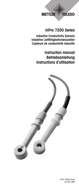
<strong>InPro</strong> <strong>7200</strong> <strong>Series</strong>Inductive Conductivity SensorsInduktive LeitfähigkeitsmesszellenCapteurs de conductivité inductifs<strong>Instruction</strong> <strong>manual</strong>Betriebsanleitung<strong>Instruction</strong>s d’utilisation<strong>InPro</strong> <strong>7200</strong> <strong>Series</strong>52 001 408
English Page 3Deutsch Seite 21Français Page 39
<strong>InPro</strong> <strong>7200</strong> <strong>Series</strong> 3<strong>InPro</strong> <strong>7200</strong> <strong>Series</strong><strong>Instruction</strong> <strong>manual</strong>Subject to technical changes without prior notice.© It is strictly forbidden to reprint this instruction <strong>manual</strong> or any parts thereof.Without the written permission of <strong>Mettler</strong>-<strong>Toledo</strong> GmbH, Process Analytics,Industrie Nord, 8902 Urdorf, Switzerland, no section or excerpt whatsoevermay be reproduced or with the assistance of electronic systems beedited, duplicated or distributed, in particular in the form of photocopies, photographs,magnetic media or other recording methods. All rights reserved,especially the right of duplication and translation as well as in regard to patentand registration rights.<strong>Mettler</strong>-<strong>Toledo</strong> GmbH, 8606 Greifensee, Switzerland© 08/04 <strong>Mettler</strong>-<strong>Toledo</strong> GmbH, CH-8606 Greifensee <strong>InPro</strong> <strong>7200</strong> <strong>Series</strong>Printed in Switzerland 52 001 408
4 <strong>InPro</strong> <strong>7200</strong> <strong>Series</strong>Contents1 Introduction..........................................................................51.1 General.................................................................................51.2 Safety <strong>Instruction</strong>s..................................................................52 Sensor ................................................................................62.1 Sensor Certification Specifications ............................................62.2 Sensor Identification ...............................................................62.3 Standard Specifications ..........................................................72.4 Sensor Specifications .............................................................73 Sensor Applications ............................................................114 Sensor Installation..............................................................124.1 Installation Notes .................................................................124.2 Flange Installation ...............................................................134.3 Bushing Installation ............................................................144.4 Sanitary Installation..............................................................144.5 Immersion Installation ..........................................................154.6 In-Line Installation ...............................................................155 Junction Box Installation.....................................................165.1 Junction Box Wiring.............................................................166 Degaussing and Sensor Resistance Check............................176.1 Degaussing.........................................................................176.2 Sensor Resistance Check ......................................................177 Disposal.............................................................................188 Dimension Drawings...........................................................189 Spare Parts ........................................................................19<strong>InPro</strong> <strong>7200</strong> <strong>Series</strong> © 08/04 <strong>Mettler</strong>-<strong>Toledo</strong> GmbH, CH-8606 Greifensee52 001 408 Printed in Switzerland
<strong>InPro</strong> <strong>7200</strong> <strong>Series</strong> 51 Introduction1.1 GeneralThe inductive Sensors <strong>InPro</strong> <strong>7200</strong> <strong>Series</strong> are intended to be usedwith Transmitter Cond Ind 7100 e, CondI 7100/2H, CondI7100/2(X)H, or M 700 (module Cond Ind 7700) to measureconductivity and concentration of liquids. Sensors are availablein a number of materials suitable for a variety of conditions.The sensors measure an induced current in a loop of solution.Two toroidally wound coils are encapsulated in close proximitywithin the sensor which is immersed in the solution. An ac signal,applied to one toroidal coil, induces a current in the secondcoil which is directly proportional to the conductance of the solution.1.2 Safety <strong>Instruction</strong>sDangersAn electrical shock hazard may be present under sensor faultconditions when sensor is located in process fluids at electricalpotentials above 30 V rms or 60 V dc. In order to prevent electricalshock hazard, remove sensor from process or de-energizepower to process prior to performing maintenance on theTransmitter Cond Ind 7100 e, CondI 7100/2H, CondI7100/2(X)H, or M 700.Certain units described in this instruction <strong>manual</strong> containelectrical shock hazard potential. Maintenance should be performedby qualified personnel only. During maintenance,remove power to avoid severe injury or death.When performing maintenance, wear appropriate, protectiveclothing including safety goggles. Escaping chemicals underpressure can cause severe injury including blindness.WarningsUse care when connecting and disconnecting high pressure serviceconnections. Use proper gloves and follow the recommendedprocedures to avoid severe injury to personnel ordamage to equipment.When processing hazardous liquids, follow the recommendedprocedures. Failure to do so could result in injury to personneland damage to equipment.Use only METTLER TOLEDO recommended replacement parts.Substitution parts could result in damage to equipment, damageto the process, and/or injury to personnel.Be careful to avoid touching exposed circuits and components.Potential shock hazards are present.© 08/04 <strong>Mettler</strong>-<strong>Toledo</strong> GmbH, CH-8606 Greifensee <strong>InPro</strong> <strong>7200</strong> <strong>Series</strong>Printed in Switzerland 52 001 408
6 <strong>InPro</strong> <strong>7200</strong> <strong>Series</strong>2 Sensor2.1 Sensor Certification SpecificationsTesting Laboratory, Conditions of Suitable SensorTypes of Protection Certification Typesand Area ClassificationFM Certification Transmitter CondI7100/2(X)H <strong>InPro</strong> <strong>7200</strong>I.S. Class 1 Div 1 <strong>InPro</strong> 7201Group A – G <strong>InPro</strong> 7202T5 at maximum ambienttemperature of 85 ºCATEX intrinsically safe for Transmitter CondI7100/2(X)H <strong>InPro</strong> <strong>7200</strong>II 1 GD EEx ia IIC T3...T6 and M 700X <strong>InPro</strong> 7201According to EC-type test <strong>InPro</strong> 7202certificate KEMA 03 ATEX 1462 XTable 1: Sensor Certification SpecificationsNote: These sensors have been designed to meet the electricalsafety descriptions noted In the table above. For detailed informationcontact your METTLER TOLEDO representative.2.2 Sensor IdentificationA sensor can be identified by the model code located on bothends of the cable. Refer to «Sensor Applications» section for sensorapplication information.6 m (20 ft)Agency labelImage of labelModel labelImage of labelFigure 1: Sensor IdentificationDate codeThe date code identifies the year and week of manufacture (seeFigure 1). In the example 2B0312 XXX serial 03 identifies theyear of manufacture as 2003, and 12, the week of manufacturein that year. The additional numbers are the serial number.Entity parameters as follows:U i = 7.5 V I i = 70 mAP i = 0.4 W L i = 7.8 mHThe effective internal capacitance C i is negligibly small.<strong>InPro</strong> <strong>7200</strong> <strong>Series</strong> © 08/04 <strong>Mettler</strong>-<strong>Toledo</strong> GmbH, CH-8606 Greifensee52 001 408 Printed in Switzerland
<strong>InPro</strong> <strong>7200</strong> <strong>Series</strong> 72.3 Standard SpecificationsWetted PartsSee Table 2 “Sensor Specifications”.CableIntegral, 6 m (20 ft) multi-screened (multi-shielded) cable withthe following jacket material:<strong>InPro</strong> <strong>7200</strong>; irradiated polyolefin jacket<strong>InPro</strong> 7201; PTFE jacket<strong>InPro</strong> 7202; irradiated polyolefin jacketMountingAll sensor extensions contain an O-ring and truncated3/4"-14 NPSM pipe thread.Insertion Mounting: Sensors are used with threaded bushings orflanges that form a process seal against sensor O-ring.Note: When mounted in-line, the sensors must be installed(centered) in a minimum pipe size to avoid pipe wall effects(DN 80 or 3").2.4 Sensor Specifications<strong>InPro</strong> <strong>7200</strong> <strong>InPro</strong> 7201 <strong>InPro</strong> 7202Measurement 0.01...2000mS/cm 0.01...2000mS/cm 0.01...2000mS/cmCell factor nominal 1) 2.15 2.15 2.15Transfer ratio 2) 48.36 48.36 48.36Material Sensor Glass-filled PEEK Glass-filled PEEK PolypropyleneO-rings* EPR EPR EPRProcess temperature –5...+120 °C –5...+200 °C –5...+80 °CMax. process press. 3) 0...17.5 bar 0...17.5 bar 0...17.5 barTemperature probe NTC 100 kΩ Pt 100 Pt 100Explosion protection FM FM FMI.S. Class 1, Div 1 I.S. Class 1, Div 1 I.S. Class 1, Div 1Group A – G Group A – G Group A – GT5 at max. ambient T5 at max. ambient T5 at max. ambienttemperature of 85 °C temperature of 85 °C temperature of 85 °CATEX intrinsically safe for ATEX intrinsically safe for ATEX intrinsically safe forII1GD EEx ia IIC T3...T6 II1GD EEx ia IIC T3...T6 II1GD EEx ia IIC T3...T6According to EC-type test According to EC-type test According to EC-type testcertificate KEMA 03 certificate KEMA 03 certificate KEMA 03ATEX 1462 X ATEX 1462 X ATEX 1462 XTable 2: Sensor Specifications* other O-ring materials on request (see chapter 9)1) This value may differ for each individual sensor and dependson the installation conditions. The exact value must be determinedwith a calibration.2) This typical value may differ for each individual sensor. Theexact value must be determined with a calibration.3) The combination of high pressure, high temperature and/oraggressive process medium reduces the sensor life span.© 08/04 <strong>Mettler</strong>-<strong>Toledo</strong> GmbH, CH-8606 Greifensee <strong>InPro</strong> <strong>7200</strong> <strong>Series</strong>Printed in Switzerland 52 001 408
8 <strong>InPro</strong> <strong>7200</strong> <strong>Series</strong>Special conditionsThe maximum permissible process temperature should beobtained from the following table according to the temperatureclass:Temperature classT6 85 °CT5 100 °CT4 135 °CT3 200 °CMaximum process temperatureMETTLER TOLEDO offers a variety of fittings and process adaptersfor a simple installation of the inductive sensors into the process.The measurement range is defined for sensors used with TransmitterCond Ind 7100 e, CondI7100/2H, CondI7100/2(X)Hor M 700.<strong>InPro</strong> <strong>7200</strong> <strong>Series</strong> © 08/04 <strong>Mettler</strong>-<strong>Toledo</strong> GmbH, CH-8606 Greifensee52 001 408 Printed in Switzerland
<strong>InPro</strong> <strong>7200</strong> <strong>Series</strong> 9ATEX certificate© 08/04 <strong>Mettler</strong>-<strong>Toledo</strong> GmbH, CH-8606 Greifensee <strong>InPro</strong> <strong>7200</strong> <strong>Series</strong>Printed in Switzerland 52 001 408
10 <strong>InPro</strong> <strong>7200</strong> <strong>Series</strong>Declaration of conformity<strong>InPro</strong> <strong>7200</strong> <strong>Series</strong> © 08/04 <strong>Mettler</strong>-<strong>Toledo</strong> GmbH, CH-8606 Greifensee52 001 408 Printed in Switzerland
<strong>InPro</strong> <strong>7200</strong> <strong>Series</strong> 113 Sensor ApplicationsNotes:– PEEK is a thermoplastic material with excellent strength andchemical resistance properties over a wide range of processtemperatures and pressures. METTLER TOLEDO recommendsusing PEEK preferentially for all applications that qualify.– PEEK material displays excellent chemical resistance tomost aqueous solutions of acids, bases, and salts. It is alsoexcellent for organic solvents such as toluene, ethyl acetate,acetone, gasoline, and carbon tetrachloride. It is notrecommended for sulfuric or nitric acid solutions above70 %, nor is it recommended for Oleum applications.SensorDesignation<strong>InPro</strong> <strong>7200</strong><strong>InPro</strong> 7201<strong>InPro</strong> 7202ApplicationThis sensor is suitable for the majority of all electrodelessconductivity applications. Its compact size enablesit to be mounted in a multitude of methods, including insertion(flange, bushing), and immersion. Typical applicationsinclude salinity and brine measurements, steelpickling, scrubbing towers, ion exchange regeneration,plating baths, rinse water, caustic metal cleaning, andtextile measurements in scouring, mercerizing, and carbonizingbaths.This sensor is identical in physical size and appearanceto the <strong>InPro</strong> <strong>7200</strong> sensor and may be applied to any ofthe applications identified which have intermittent or continuouslyhigh temperatures. Additional high temperatureapplications for which this sensor is suited includealumina-to-caustic ratio, boiler blowdown, and Cleaning-In-Place(CIP) measurements in food and relatedindustries.This general purpose, sensor may be used for most routineapplications involving low (
12 <strong>InPro</strong> <strong>7200</strong> <strong>Series</strong>4 Sensor Installation4.1 Installation NotesProper installation of the sensor is important for efficient andaccurate operation. For all applications and sensor configurations,mounting arrangements must be located so that:– Sample at the sensing area is representative of the solution.– Solution circulates actively and continuously past the sensingarea.– Position and orientation of the sensor does not trap air bubbleswithin sensing area.– Deposits of sediment or other foreign material do not accumulatewithin the sensing area.If cable is installed in a conduit (recommended), either flexibleconduit should be used or some other provision made for removalof sensor from the process.Also lubricate all O-rings with a thin film of suitable grease.Notes:– There are two grooves on the thread diameter of the sensor.The groove closest to the cable is not an O-ring groove andshould remain unoccupied. The next groove, as shown inFigure 2, is for the O-ring.– Ensure that the sensor received has the O-ring in the properposition.– Ensure that future O-ring replacement is in the proper position.Warning: Incorrect O-ring position as previously indicatedcould result in process leakage, causing injury to personnel.– There are two notches at the cable cap that line up with thebore of the sensor doughnut. These notches are an aid inpositioning the sensor in a pipe or vessel.Notch for sensorbore orientationCable capNot an O-ringgrooveBoreO-ring for process sealin flange and bushinginstallationsSensor doughnutFigure 2: Sensor overview<strong>InPro</strong> <strong>7200</strong> <strong>Series</strong> © 08/04 <strong>Mettler</strong>-<strong>Toledo</strong> GmbH, CH-8606 Greifensee52 001 408 Printed in Switzerland
<strong>InPro</strong> <strong>7200</strong> <strong>Series</strong> 134.2 Flange InstallationMETTLER TOLEDO flanges are used for permanent installationsin pipelines and tanks. Flanges are used with electrodeless conductivitysensors in systems using 2-inch and larger processpiping. Flanges come complete with locknut and a set of spacers.Refer to Table 4 for flange specifications, and to Figure 3for a typical flange installation.Note: One or two spacers are used depending on flange thickness.The O-ring must be positioned correctly for proper spacing.Flange size Part No (Set) Material*ANSI 2" 52401933 1.4435ANSI 2 1/2" 52401934 1.4435ANSI 3" 52401938 1.4435ANSI 4" 52401939 1.4435DN 50 / PN 16 52401940 1.4435DN 100 / PN 16 52401941 1.4435Table 4: Flange Specifications. *Flanges made of stainless steel aresupplied as standard with Inspection Certificate 3.1B.Typical Flange InstallationFlange and accessoriesO-ring must seaton flange I.D.Spacers (see Notes)LocknutFlange I.D.Figure 3: Flange installation© 08/04 <strong>Mettler</strong>-<strong>Toledo</strong> GmbH, CH-8606 Greifensee <strong>InPro</strong> <strong>7200</strong> <strong>Series</strong>Printed in Switzerland 52 001 408
14 <strong>InPro</strong> <strong>7200</strong> <strong>Series</strong>4.3 Bushing InstallationMETTLER TOLEDO bushings (locknuts supplied) are used forinstallations in pipelines and tanks. Refer to Table 5 for bushingspecifications and to Figure 4 for a typical bushing installation.Typical Bushing InstallationBushing with locknutFigure 4: Bushing installationMaterial Part No Thread size Rated pressure Max. temperatureat rated pressureMPa psi °C °F1.4435 52401947 G 1 1/2" NPT 1.75 250 200 390with 52401943 R 1 1/2"InspectionCertificate 52401949 G 2" NPT3.1B 52401945 R 2"PVDF 52401948 G 1 1/2" NPT 1.0 150 25 7552401944 R 1 1/2" 0.4 60 80 18052401950 G 2" NPT 0.2 30 120 25052401946 R 2"Table 5: Hex-Head Bushing Specifications4.4 Sanitary InstallationPart No Description Material Certificate52 401 952 Dairy adapter DN50 DIN 1.4435 3.1B Inspection Certificate(DIN 11851)52 401 953 Aseptic adapter DN50 DIN 1.4435 3.1B Inspection Certificate(DIN 11864-1)METTLER TOLEDO offers an adapter according to DIN 11851(DN50) as well as an aseptic adapter DIN 11864-1 (DN50) forthe inductive sensors of the <strong>InPro</strong> <strong>7200</strong> series.<strong>InPro</strong> <strong>7200</strong> <strong>Series</strong> © 08/04 <strong>Mettler</strong>-<strong>Toledo</strong> GmbH, CH-8606 Greifensee52 001 408 Printed in Switzerland
<strong>InPro</strong> <strong>7200</strong> <strong>Series</strong> 154.5 Immersion InstallationFor open tanks or inlet channel the sensor can be installed in animmersion housing InDip 550Ind.Figure 5: Immersion housing “InDip 550Ind”4.6 In-Line InstallationFor in-line applications within a metal or plastic pipe, the pipemust have a minimum diameter of DN80 (3"), and the sensorshould be aligned as closely as possible with the centerline ofthe pipe.Larger pipe diameter should be used wherever possible.Note: Whenever the minimum size pipe diameter is used, thesystem should be calibrated with the sensor in place and witha solution of known conductivity (within the range of the instrument’scalibration).© 08/04 <strong>Mettler</strong>-<strong>Toledo</strong> GmbH, CH-8606 Greifensee <strong>InPro</strong> <strong>7200</strong> <strong>Series</strong>Printed in Switzerland 52 001 408
16 <strong>InPro</strong> <strong>7200</strong> <strong>Series</strong>5 Junction Box Installation5.1 Junction Box Wiring1. Remove the junction box cover and loosen the cable connectors.2. Insert the sensor cable through the appropriate connectorand connect the numbered terminals of the sensor cable tothe corresponding numbered terminals on the terminal strip.Note: For maximum accuracy, sensor should not be locatedmore than 30 m (100 ft) from Transmitter Cond Ind7100 e, CondI7100/2H, CondI7100/2(X)H or M 700.3. Insert extension cable assembly through appropriateconnector and connect the numbered terminals of extensioncable assembly opposite the corresponding number.Junction box160Figure 6: Junction box “ZU 0074X”Figure 7: Junction box “ZU 0307”<strong>InPro</strong> <strong>7200</strong> <strong>Series</strong> © 08/04 <strong>Mettler</strong>-<strong>Toledo</strong> GmbH, CH-8606 Greifensee52 001 408 Printed in Switzerland
<strong>InPro</strong> <strong>7200</strong> <strong>Series</strong> 176 Degaussing and Sensor Resistance Check6.1 DegaussingTo degauss a sensor, use a degaussing tool such as that usedfor erasing magnetic tape. With degaussing tool power on, bringthe tool close to the sensor and move the tool slowly around thesensor in close proximity. Then slowly move the tool away fromthe sensor (min. 20 cm). Turn tool power off.6.2 Sensor Resistance CheckNote: Use a high impedance meter when making these checksbecause a low impedance meter can cause the probe to becomemagnetized. Refer to Figure 8 for sensor cable resistances.Sensor cable resistancesFlow celljacketed cableSECPRIblackwhiteDrain 1123RTDredDrain 2brownblue4567Power groundprovided throughconduitConnection1 to 21 or 2 to 31 or 2 to 4 or 54 to 54 or 5 to 6 or 76 to 7Resistance Ω0 (short)infiniteinfinite0 (short)infinite100 kΩ, ±1% at 25 °C (77 °F) for sensor<strong>InPro</strong> <strong>7200</strong> and <strong>InPro</strong> 7202109.7 kΩ, ±1% at 25 °C (77 °F) for sensor<strong>InPro</strong> 7201Figure 8: Sensor cable resistances© 08/04 <strong>Mettler</strong>-<strong>Toledo</strong> GmbH, CH-8606 Greifensee <strong>InPro</strong> <strong>7200</strong> <strong>Series</strong>Printed in Switzerland 52 001 408
18 <strong>InPro</strong> <strong>7200</strong> <strong>Series</strong>7 DisposalThe sensors described in this <strong>manual</strong> usually cannot be repaired.Their disposal is to the responsability of the user. Sensorscontain electronic components (coils, cables) that requirespecial disposal without any health hazard for humans, and withno risk of harm for the environment. Please refer to your localregulations.8 Dimension DrawingsOrder No. Designation Ø A Ø B Ø C D Spacer Spacerin front at the back52 401 940 Flange DN50/PN16 3.1B 125 4x18 165 18 1x4.75 1x9.552 401 941 Flange DN100/PN16 3.1B 180 8x18 220 20 1x4.75 1x9.552 401 933 Flange ANSI 2" 3.1B 120.7 4x19 152.4 12.7 1x9.5 1x9.552 401 934 Flange ANSI 2 1/2" 3.1B 139.7 4x19 177.8 14.2 1x9.5 1x9.552 401 938 Flange ANSI 3" 3.1B 152.4 4x19 190.5 15.7 1x9.5 1x9.552 401 939 Flange ANSI 4" 3.1B 190.5 8x19 228.6 17.5 1x4.75 1x9.56m Cable6 m CableLocknutØ BBLocknutDFlangeØ ASpacerSensor120Ø C(120 + Spacer)CBushingASensorØ 36Figure 9: FlangeFigure 10: Threaded bushingOrder-No. Designation A B C52 401 943 Threaded bushing R 1 1/2" 3.1B R 1 1/2" SW60 2252 401 944 Threaded bushing R 1 1/2" PVDF R 1 1/2" SW60 2252 401 945 Threaded bushing R 2" 3.1B R 2" SW75 2452 401 946 Threaded bushing R 2" PVDF R 2" SW75 2452 401 947 Threaded bushing G 1 1/2" NPT 3.1B G 1 1/2" NPT SW60 2252 401 948 Threaded bushing G 1 1/2" NPT PVDF G 2" NPT SW60 2252 401 949 Threaded bushing G 2" 3.1B G 2" NPT SW75 2452 401 950 Threaded bushing G 2" PVDF G 2" NPT SW75 24<strong>InPro</strong> <strong>7200</strong> <strong>Series</strong> © 08/04 <strong>Mettler</strong>-<strong>Toledo</strong> GmbH, CH-8606 Greifensee52 001 408 Printed in Switzerland
Ø C<strong>InPro</strong> <strong>7200</strong> <strong>Series</strong> 19Aseptic adapterDairy adapter6 m Cable6 m CableLocknutLocknutAdapterAdapterØ ARingnutØ ARingnutDØ BØ BAseptic weld-in socketDWeld-in socketSensorSensorØ CDIN 11864-1 DIN 11851Figure 11: Sanitary adapterOrder No. Designation DIN Ø A Ø B Ø C D52 401 952 Dairy adapter 11851 58 92 87 14052 401 953 Aseptic adapter 11864-1 61 92 87 1406 m CableImmersion tubeInDip 550IndLocknutSensor adapter120Sensor¯ 361.42Figure 12: Immersion housing9 Spare PartsOrder No. Description Material Used for52 401 942 Set locknut with spacers 1.4435 Flange installation52 401 980 Set Locknut 1.4435 Bushing installationSanitary/Aseptic installationImmersion installation20 303 1112 O-ring EPDM (FDA) <strong>InPro</strong> <strong>7200</strong> <strong>Series</strong>20 304 1100 O-ring Kalrez (FDA) <strong>InPro</strong> <strong>7200</strong> <strong>Series</strong>© 08/04 <strong>Mettler</strong>-<strong>Toledo</strong> GmbH, CH-8606 Greifensee <strong>InPro</strong> <strong>7200</strong> <strong>Series</strong>Printed in Switzerland 52 001 408
20 <strong>InPro</strong> <strong>7200</strong> <strong>Series</strong><strong>InPro</strong> <strong>7200</strong> <strong>Series</strong> © 08/04 <strong>Mettler</strong>-<strong>Toledo</strong> GmbH, CH-8606 Greifensee52 001 408 Printed in Switzerland
<strong>InPro</strong> <strong>7200</strong> <strong>Series</strong> 21<strong>InPro</strong> <strong>7200</strong> <strong>Series</strong>BetriebsanleitungTechnische Änderungen ohne vorherige Anzeige sind vorbehalten.© Der Nachdruck dieser Betriebsanleitung, auch auszugsweise, ist verboten.Ohne schriftliche Bewilligung der Firma <strong>Mettler</strong>-<strong>Toledo</strong> GmbH, ProcessAnalytics, Industrie Nord, CH-8902 Urdorf, dürfen keine Teile davon in irgendeinerForm reproduziert oder unter Anwendung elektronischer Systeme, insbesonderein Form von Fotokopien, Fotos, Magnetverfahren oder anderenAufzeichnungsarten, verarbeitet, vervielfältigt oder verbreitet werden. AlleRechte, insbesondere das Recht der Vervielfältigung und Übersetzung sowiePatent- oder Registrierungsrechte, sind vorbehalten.<strong>Mettler</strong>-<strong>Toledo</strong> GmbH, CH-8606 Greifensee© 08/04 <strong>Mettler</strong>-<strong>Toledo</strong> GmbH, CH-8606 Greifensee <strong>InPro</strong> <strong>7200</strong> <strong>Series</strong>Printed in Switzerland 52 001 408
22 <strong>InPro</strong> <strong>7200</strong> <strong>Series</strong>Inhaltsverzeichnis1 Einleitung...........................................................................231.1 Allgemeine Hinweise ............................................................231.2 Sicherheitshinweise..............................................................232 Sensor ...............................................................................242.1 Sensorzertifizierung ..............................................................242.2 Sensoridentifikation ..............................................................242.3 Standardspezifikationen........................................................252.4 Sensorspezifikationen...........................................................253 Einsatzgebiete der Sensoren ...............................................294 Sensor Installation..............................................................304.1 Installationshinweise ............................................................304.2 Einbau mittels Flansch ........................................................314.3 Einbau mittels Buchse .........................................................324.4 Hygienesichere Installation....................................................324.5 Installation mittels Eintaucharmatur........................................334.6 In-Line-Installation ...............................................................335 Klemmenkasten..................................................................345.1 Verdrahtung des Klemmenkastens .........................................346 Entmagnetisierung und Sensorüberprüfung ..........................356.1 Entmagnetisierung ...............................................................356.2 Überprüfung des Sensors ......................................................357 Entsorgung .........................................................................368 Masszeichnungen ...............................................................369 Ersatzteile..........................................................................37<strong>InPro</strong> <strong>7200</strong> <strong>Series</strong> © 08/04 <strong>Mettler</strong>-<strong>Toledo</strong> GmbH, CH-8606 Greifensee52 001 408 Printed in Switzerland
<strong>InPro</strong> <strong>7200</strong> <strong>Series</strong> 231 Einleitung1.1 Allgemeine HinweiseDie induktiven Sensoren der <strong>InPro</strong> <strong>7200</strong> Serie werden zusammenmit den Transmittern Cond Ind 7100 e, CondI 7100/2H,CondI 7100/2(X)H oder M 700 (Modul Cond Ind 7700) eingesetztund sind ausschliesslich für die Messung von Leitfähigkeitenund Stoffkonzentrationen in Flüssigkeiten bestimmt. DieSensoren sind in verschiedenen Werkstoffausführungen fürunterschiedliche Anwendungen erhältlich.Die Sensoren <strong>InPro</strong> <strong>7200</strong> Serie arbeiten nach dem Prinzip derinduktiven Leitfähigkeitsmessung. Durch die stromdurchflosseneSendespule im Sensor wird in der Messlösung eine Spannunginduziert. Dadurch fliesst in der Messlösung ein Strom, derseinerseits in der Empfängerspule des Sensors eine Spannunginduziert. Der dabei fliessende Induktionsstrom in der Empfängerspuleist direkt proportional zur Leitfähigkeit der Messlösung.1.2 SicherheitshinweiseAchtung Stromschlaggefahr! Die Berührung der elektrischenAnschlüsse von beschädigten Sensoren, die sich in einem Prozessmediummit einem elektrischen Potential grösser als30 V RMS oder 60 V Gleichstrom befinden, kann zu einemgefährlichen Stromschlag führen. Um die Gefahr eines Stromschlageszu verhindern, entfernen Sie vor Wartungsarbeitenam Transmitter Cond Ind 7100 e, CondI 7100/2H, CondI7100/2(X)H oder M 700 den angeschlossenen Sensor ausdem Prozess, oder trennen Sie den Prozess von jeglicherStromzufuhr ab.Bei eingeschaltetem Messsystem kann die Berührung von ungeschütztenStromkreisen und Komponenten (Anschlüsse, Kabel)zu einem Stromschlag führen. Zur Vermeidung eines gefährlichenStromschlages ist das Messsystem vor Wartungsarbeitenvon der Stromquelle zu trennen. Zudem dürfen Wartungsarbeitennur durch entsprechend qualifiziertes Personalausgeführt werden.Achtung! Entweichende Prozessmedien (unter Druck stehendeFlüssigkeiten, giftige oder anderweitig gefährliche Flüssigkeiten,etc.) können zu schwersten Verletzungen (z.B. Blindheit, Vergiftung,etc.) und/oder zu Sachschäden führen oder die Umweltgefährden. Tragen Sie deshalb für alle Wartungsarbeiten die vorgeschriebeneSchutzbekleidung (Handschuhe, Schutzbrille,Atemschutz,etc.) und befolgen Sie die vorgeschriebene Vorgehensweisebeim An- und Abkoppeln von Hochdruckverbindungenund beim Umgang mit gefährlichen Flüssigkeiten.Verwenden Sie nur die von METTLER TOLEDO empfohlenenErsatzteile. Fremdteile können zu Material- beziehungsweiseProzessschäden sowie zu Verletzungen von Personen führen.© 08/04 <strong>Mettler</strong>-<strong>Toledo</strong> GmbH, CH-8606 Greifensee <strong>InPro</strong> <strong>7200</strong> <strong>Series</strong>Printed in Switzerland 52 001 408
24 <strong>InPro</strong> <strong>7200</strong> <strong>Series</strong>2 Sensor2.1 SensorzertifizierungPrüflaboratorium, Zertifizierungsbasis EntsprechendeSchutzklassenSensorenund GeltungsbereichFM-Zertifizierung Transmitter CondI7100/2(X)H <strong>InPro</strong> <strong>7200</strong>I.S. Klasse 1 Div 1 <strong>InPro</strong> 7201Gruppe A – G <strong>InPro</strong> 7202T5 bei maximalerUmgebungstemp. von 85 °CEigensichere Ausführung mit Transmitter CondI7100/2(X)H <strong>InPro</strong> <strong>7200</strong>ATEX-Zulassung für und M 700X <strong>InPro</strong> 7201II 1 GD EEx ia IIC T3...T6 <strong>InPro</strong> 7202Gemäss EG-Typenprüfung,Zertifikat KEMA 03 ATEX 1462 XTabelle 1: SensorzertifizierungHinweis: Die Ausführungen der verschiedenen Sensoren entsprechenden Stromschutzvorschriften gemäss obiger Tabelle.Für detailliertere Informationen, setzen Sie sich mit Ihrer lokalenMETTLER TOLEDO Vertretung in Verbindung.2.2 SensoridentifikationDie Identifizierung des Sensors erfolgt durch die Typenbezeichnung,die an beiden Enden des Kabels angebracht ist. Für diegeeigneten Einsatzgebiete des Sensors, siehe Kapitel 3 “Einsatzgebieteder Sensoren”.6 m (20 ft)Agency labelImage of labelModel labelImage of labelAbbildung 1: SensoridentifikationDatumscodeDer Datumscode gibt Aufschluss über das Jahr und die Wocheder Herstellung (siehe Abb. 1). Im Beispiel 2B0312 xxx identifiziert03 das Herstellungsjahr als 2003, und 12 steht für dieentsprechende Woche des Herstellungsjahres. Die zusätzlichenZahlen bilden die Serienummer.Charakteristikparameter wie folgt:U i = 7.5 V I i = 70 mAP i = 0.4 W L i = 7.8 mHDie effektive innere Kapazität C i ist vernachlässigbar klein.<strong>InPro</strong> <strong>7200</strong> <strong>Series</strong> © 08/04 <strong>Mettler</strong>-<strong>Toledo</strong> GmbH, CH-8606 Greifensee52 001 408 Printed in Switzerland
<strong>InPro</strong> <strong>7200</strong> <strong>Series</strong> 252.3 StandardspezifikationenMediumberührte TeileSiehe Tabelle 2 “Sensorspezifikationen”.KabelIntegrales, 6 m (20 ft) langes, mehrfachabgeschirmtes Fixkabelmit folgendem Kabelmantel:<strong>InPro</strong> <strong>7200</strong>: Polyolefin<strong>InPro</strong> 7201: PTFE<strong>InPro</strong> 7202: PolyolefinMontageSämtliche Sensorschäfte sind mit einem O-Ring und einem konischen3/4"-14 NPSM-Rohrgewinde ausgestattet.Installation: Der Einbau der Sensoren erfolgt über Gewindebuchsenoder Flansche, die zusammen mit dem O-Ring desSensors den Prozessraum vollkommen abdichten.Hinweis: Um Messeinflüsse durch die Rohrwand zu vermeiden,muss der Sensor bei In-Line-Anordnungen in der Rohrleitungzentriert eingebaut werden und die Rohrleitung einen minimalenDurchmesser von DN 80 (3") aufweisen.2.4 Sensorspezifikationen<strong>InPro</strong> <strong>7200</strong> <strong>InPro</strong> 7201 <strong>InPro</strong> 7202Messbereich 0.01...2000mS/cm 0.01...2000mS/cm 0.01...2000mS/cmZellfaktor nominal 1) 2.15 2.15 2.15Übertrag.-Faktor 2) 48.36 48.36 48.36Werkstoff Sensor Glasgefülltes PEEK Glasgefülltes PEEK PolypropylenO-Ringe* EPR EPR EPRProzess-Temperatur –5...+120 °C –5...+200 °C –5...+80 °CMax. Prozessdruck 3) 0...17.5 bar 0...17.5 bar 0...17.5 barTemperaturfühler NTC 100 kΩ Pt 100 Pt 100Explosionsschutz FM FM FMI.S. Klasse 1, Div 1 I.S. Klasse 1, Div 1 I.S. Klasse 1, Div 1Gruppe A – G Gruppe A – G Gruppe A – GT5 bei max. Umgeb.- T5 bei max. Umgeb.- T5 bei max. Umgeb.-Temperatur von 85°C Temperatur von 85°C Temperatur von 85°CEigensichere Ausführung Eigensichere Ausführung Eigensichere Ausführungmit ATEX-Zulassung für mit ATEX-Zulassung für mit ATEX-Zulassung fürII1GD EEx ia IIC T3...T6 II1GD EEx ia IIC T3...T6 II1GD EEx ia IIC T3...T6Gem. EG-Typenprüfung, Gem. EG-Typenprüfung, Gem. EG-Typenprüfung,Zertifikat KEMA 03 Zertifikat KEMA 03 Zertifikat KEMA 03ATEX 1462 X ATEX 1462 X ATEX 1462 XTabelle 2: Sensorspezifikationen* andere O-Ring-Werkstoffe auf Anfrage (siehe Kapitel 9)1) Dieser Wert kann bei jedem Sensor je nach Einbauverhältnissenverschieden sein. Der genaue Wert muss durch Kalibrierenermittelt werden.2) Dieser typische Wert kann für jeden Sensor verschieden sein.Der genaue Wert muss durch Kalibrieren ermittelt werden3) Eine Kombination von hohem Druck, hoher Temperaturund/oder aggressivem Prozessmedium verkürzt die Lebensdauerdes Sensors.© 08/04 <strong>Mettler</strong>-<strong>Toledo</strong> GmbH, CH-8606 Greifensee <strong>InPro</strong> <strong>7200</strong> <strong>Series</strong>Printed in Switzerland 52 001 408
26 <strong>InPro</strong> <strong>7200</strong> <strong>Series</strong>Besondere BedingungenDie maximal zulässigen Prozesstemperaturen sind entsprechendder Temperaturklasse der folgenden Tabelle zu entnehmen:TemperaturklasseT6 85 °CT5 100 °CT4 135 °CT3 200 °CMax. ProzesstemperaturMETTLER TOLEDO bietet eine Reihe von Adaptern an, die eineeinfache Installation der induktiven Sensoren in den Prozesserlaubt.Der Messbereich der Sensoren bezieht sich auf deren Einsatz inVerbindung mit den Transmittern Cond Ind 7100e, CondI7100/2H, CondI7100/2(X)H oder M 700.<strong>InPro</strong> <strong>7200</strong> <strong>Series</strong> © 08/04 <strong>Mettler</strong>-<strong>Toledo</strong> GmbH, CH-8606 Greifensee52 001 408 Printed in Switzerland
<strong>InPro</strong> <strong>7200</strong> <strong>Series</strong> 27ATEX Zertifikat© 08/04 <strong>Mettler</strong>-<strong>Toledo</strong> GmbH, CH-8606 Greifensee <strong>InPro</strong> <strong>7200</strong> <strong>Series</strong>Printed in Switzerland 52 001 408
28 <strong>InPro</strong> <strong>7200</strong> <strong>Series</strong>Konformitätserklärung<strong>InPro</strong> <strong>7200</strong> <strong>Series</strong> © 08/04 <strong>Mettler</strong>-<strong>Toledo</strong> GmbH, CH-8606 Greifensee52 001 408 Printed in Switzerland
<strong>InPro</strong> <strong>7200</strong> <strong>Series</strong> 293 Einsatzgebiete der SensorenHinweise:– PEEK ist ein thermoplastisches Material mit hervorragendenEigenschaften bezüglich Festigkeit und chemischer Beständigkeitüber einen weiten Bereich von Prozesstemperaturenund -drücken. METTLER TOLEDO empfiehlt die Verwendungvon PEEK-Sensoren in allen Anwendungen, die entsprechendeAnforderungen an den Sensor stellen.– PEEK weist eine sehr gute chemische Beständigkeit gegendie meisten säure- oder alkalihaltigen, wässrigen Lösungensowie gegen Salze auf. Das Material bietet auch einen ausgezeichnetenSchutz gegen organische Lösungsmittel wieToluol, Ethylacetat, Aceton, Benzin, Tetrachlormethan etc..Es wird jedoch weder für Anwendungen in über 70%iger -Schwefel- oder Salpetersäure noch in Oleum empfohlen.SensorBezeichnung<strong>InPro</strong> <strong>7200</strong><strong>InPro</strong> 7201<strong>InPro</strong> 7202ApplikationDieser Sensor ist für die meisten Leitfähigkeitsapplikationengeeignet. Die kompakte Grösse erlaubt eine Vielzahlvon Einbaumöglichkeiten inklusive des Einbaus mittelsFlansch oder Gewindebuchse oder den Einbau in einTauchrohr. Typische Applikationen sind: Messungen desSalzgehaltes und Solemessungen, Messungen in Stahlbeizen,Gaswaschtürmen, beim Regenerieren von Ionenaustauschern,in Verzinkungsbädern, von Spülwasser, inalkalische Metallreinigungen, sowie Messungen im Textilbereichwie z.B. Vorwaschen, Merzerisieren und in Karbonisierungsbädern.Dieser Sensor ist identisch mit dem <strong>InPro</strong> <strong>7200</strong> (sowohlin der Grösse als auch im Aussehen) und kann für diegleichen Applikationen (wie oben aufgelistet) eingesetztwerden, bei denen die Temperatur zeitweise oder konstanthoch ist. Weitere für diesen Sensor geeignete Hochtemperaturanwendungensind Leichtmetallgewinnung,Abschlämmen von Dampfkesseln und Cleaning-In-Place-Messungen (CIP) in der Lebensmittelindustrie undverwandten Industrien.Dieser Mehrzwecksensor kann für die meisten Routineanwendungeneingesetzt werden, so zum Beispiel imZusammenhang mit anorganischen Säuren niedrigerKonzentration (
30 <strong>InPro</strong> <strong>7200</strong> <strong>Series</strong>4 Sensor Installation4.1 InstallationshinweiseDie korrekte Installation eines Sensors ist entscheidend für dessenkorrekte Funktion. Für sämtliche Anwendungen und Sensorkonfigurationenmuss eine Einbauanordnung gewählt werden,die sicherstellt, dass:– das Messmedium im Bereich des Sensors für den gesamtenProzess repräsentativ ist.– das Prozessmedium im Sensormessbereich aktiv und kontinuierlichin Bewegung ist.– die Position und Ausrichtung des Sensors das Einschliessenvon Luftblasen im Messfeld des Sensors verunmöglicht.– sich keine Sedimente oder andere Fremdstoffe im Messfelddes Sensors ablagern können.Zum Schutz des Sensorkabels wird empfohlen, dieses in einemSchutzrohr (flexibel oder fest) zu verlegen. Bei Verwendungeines festen Schutzrohres ist darauf zu achten, dass ein einfacherAusbau des Sensors aus dem Prozess gewährleistet ist.Sämtliche O-Ringe sind mit einem dünnen Film eines geeignetenFettes zu schmieren.Hinweise:– Der Sensor besitzt (am Gewindedurchmesser) zwei Nuten.Die gegen das Sensorgehäuse gerichtete Nut dient zurAufnahme des O-Ringes (siehe Abb. 2). Die kabelseitigeNute muss frei bleiben.– Stellen Sie sicher, dass Ihr Sensor mit einem korrekt positioniertenO-Ring geliefert wurde und dass dieser bei einemkünftigen Austausch wieder in der richtigen Nute eingesetztwird.Warnung: Eine falsche O-Ring-Positionierung kann zu Undichtheitund folglich zu Personen- und/oder Sachschädenführen.– Am oberen Ende des Sensors (bei der Kabelkappe) befindensich zwei gegenüberliegende Kerben, die die Positionder Bohrung im Sensorgehäuse anzeigen. Diese Kerbendienen als Positionierhilfe beim Einbau des Sensors ineinem Rohr oder Kessel.Nocken für SensororientierungKabelkappekeine O-RingNuteSensoröffnungSensorgehäuseO-Ring Dichtung für Einbauin Flansche undGewindebuchsenAbbildung 2: Sensor Übersicht<strong>InPro</strong> <strong>7200</strong> <strong>Series</strong> © 08/04 <strong>Mettler</strong>-<strong>Toledo</strong> GmbH, CH-8606 Greifensee52 001 408 Printed in Switzerland
<strong>InPro</strong> <strong>7200</strong> <strong>Series</strong> 314.2 Einbau mittels FlanschDie von METTLER TOLEDO gelieferten Flansche sind für diepemanente Installation des Sensors in Rohrleitungen und Behälternvorgesehen. Flansche werden für den Einbau der induktivenLeitfähigkeitssensoren in Systemen mit Prozessverrohrung>2" verwendet. Die Flansche werden komplett mit Sicherungsmutterund einem Set mit Distanzringen geliefert. Beachten Siebitte Tabelle 4 für die Flanschspezifikationen, sowie Abb. 3 füreine typische Einbauanordnung mittels Flansch.Hinweis: Zur korrekten Positionierung des O-Ringes im Flansch-Innendurchmesser werden, abhängig von der Flanschdicke, einoder zwei Distanzringe benötigt.Flanschgrösse Bestell-Nr. Werkstoff*ANSI 2” 52401933 1.4435ANSI 2 1/2” 52401934 1.4435ANSI 3” 52401938 1.4435ANSI 4” 52401939 1.4435DN 50 / PN 16 52401940 1.4435DN 100 / PN 16 52401941 1.4435Tabelle 4: Flansch Spezifikationen. *Flansche aus rostfreiem Stahl werdenstandardmässig mit einem Abnahmeprüfzeugnis 3.1B geliefert.Typische Installation mittels FlanschFlansch mit ZubehörO-Ring muss beim FlanschinnendurchmesserdichtenDistanzringe(siehe Bemerkung)SicherungsmutterFlansch InnendurchmesserAbbildung 3: Installation mittels Flansch© 08/04 <strong>Mettler</strong>-<strong>Toledo</strong> GmbH, CH-8606 Greifensee <strong>InPro</strong> <strong>7200</strong> <strong>Series</strong>Printed in Switzerland 52 001 408
32 <strong>InPro</strong> <strong>7200</strong> <strong>Series</strong>4.3 Einbau mittels BuchseDie von METTLER TOLEDO gelieferten Buchsen (mit Sicherungsmutter)sind für die Installation des Sensors in Rohrleitungen undBehältern vorgesehen. Beachten Sie Tabelle 5 für die Buchsenspezifikationensowie Abb. 4 für eine typische Installation mittelsBuchse.Typische Installation mittels BuchseBuchse mit SicherungsmutterAbbildung 4: Installation mittels BuchseWerkstoff Bestell-Nr. Gewinde Nenndruck Max. Temperaturbei NenndruckMPa psi °C °F1.4435 52401947 G 1 1/2” NPT 1.75 250 200 390mit 52401943 R 1 1/2”Abnahmeprüfzeugnis52401949 G 2” NPT3.1B 52401945 R 2”PVDF 52401948 G 1 1/2” NPT 1.0 150 25 7552401944 R 1 1/2” 0.4 60 80 18052401950 G 2” NPT 0.2 30 120 25052401946 R 2”Tabelle 5: Spezifikationen für Buchsen mit Sechskantkopf4.4 Hygienesichere InstallationBestell-Nr. Beschreibung Werkstoff Zertifikat52 401 952 Milchrohradapter DN50 DIN 1.4435 3.1B Abnahmeprüfzeugnis(DIN 11851)52 401 953 Aseptik-Adapterset DN50 DIN 1.4435 3.1B Abnahmeprüfzeugnis(DIN 11864-1)METTLER TOLEDO bietet ein Adapterset für den Einbau in Milchrohrverschraubungennach DIN 11851 sowie ein Adapterset fürden Einbau in Aseptikrohrverschraubung nach DIN 11864-1 an.<strong>InPro</strong> <strong>7200</strong> <strong>Series</strong> © 08/04 <strong>Mettler</strong>-<strong>Toledo</strong> GmbH, CH-8606 Greifensee52 001 408 Printed in Switzerland
<strong>InPro</strong> <strong>7200</strong> <strong>Series</strong> 334.5 Installation mittels EintaucharmaturBei offenen Behältern oder Einlaufrinnen kann der Sensor mittelsEintaucharmatur InDip 550Ind installiert werden.Abbildung 5: Eintaucharmatur “InDip 550Ind”4.6 In-Line-InstallationFür In-Line-Applikationen muss das Rohr (Metall- oder Kunststoffrohr)einen Mindestdurchmesser von DN80 (3”) aufweisenund der Sensor so genau wie möglich mit der Mittellinie des Rohresfluchten.Wenn immer möglich sollten grössere Rohrdurchmesser gewähltwerden.Hinweis: Falls der Sensor in ein Rohr mit dem minimal zulässigenDurchmesser eingebaut wird, sollte das System mit eingebautemSensor und mit einer Lösung von bekannter Leitfähigkeit(innerhalb des Kalibrierbereiches des Transmitters)kalibriert werden.© 08/04 <strong>Mettler</strong>-<strong>Toledo</strong> GmbH, CH-8606 Greifensee <strong>InPro</strong> <strong>7200</strong> <strong>Series</strong>Printed in Switzerland 52 001 408
34 <strong>InPro</strong> <strong>7200</strong> <strong>Series</strong>5 Klemmenkasten5.1 Verdrahtung des Klemmenkastens1. Deckel des Klemmenkastens entfernen und die Kabelmuffenlösen.2. Sensorkabel durch die entsprechende Muffe einschieben unddie nummerierten Kabelabschlüsse an die entsprechendnummerierten Klemmen der Klemmenleiste anschliessen.Hinweis: Zur Gewährleistung der maximalen Genauigkeitsollte der Sensor nicht weiter als 30 m (100 ft) vom TransmitterCond Ind 7100 e, CondI 7100/2H, CondI7100/2(X)H oder M 700 entfernt sein.3. Verlängerungskabel durch die entsprechende Muffe einschiebenund die nummerierten Kabelabschlüsse an die entsprechendenGegennummern anschliessen.Klemmenkasten160Abbildung 6: Klemmenkasten “ZU 0074X”Abbildung 7: Klemmenkasten “ZU 0307”<strong>InPro</strong> <strong>7200</strong> <strong>Series</strong> © 08/04 <strong>Mettler</strong>-<strong>Toledo</strong> GmbH, CH-8606 Greifensee52 001 408 Printed in Switzerland
<strong>InPro</strong> <strong>7200</strong> <strong>Series</strong> 356 Entmagnetisierung und Sensorüberprüfung6.1 EntmagnetisierungUm einen Sensor zu entmagnetisieren, verwenden Sie ein Entmagnetisierungsgerätwie es für die Löschung eines Magnetbandesgebraucht wird. Das eingeschaltete Entmagnetisierungsgerätganz nah an den Sensor heranbringen, und das Geräteng um den Sensor herumbewegen. Anschliessend das Gerätlangsam vom Sensor entfernen (min. 20 cm) und erst dannabschalten.6.2 Überprüfung des SensorsHinweis: Verwenden Sie für die Überprüfung des Sensors ausschliesslichein hochohmiges Messgerät, da ein niederohmigesMessgerät den Sensor magnetisieren kann. Beachten Sie Abb. 8für Sensorkabelwiderstände.SensorkabelwiderständeSensorzelleummanteltes KabelSECPRIschwarzweissSchirm 1123RTDrotSchirm 2braunblau4567Erdung überLeitungVerbindung Widerstand Ω1 zu 20 (Kurzschluss)1 oder 2 zu 3 ∞1 oder 2 zu 4 oder 5 ∞4 zu 50 (Kurzschluss)4 oder 5 zu 6 oder 7 ∞6 zu 7100 kΩ, ±1% bei 25 °C (77 °F) für Sensor<strong>InPro</strong> <strong>7200</strong> und <strong>InPro</strong> 7202109.7 kΩ, ±1% bei 25 °C (77 °F) für Sensor<strong>InPro</strong> 7201Abbildung 8: Sensorkabelwiderstände© 08/04 <strong>Mettler</strong>-<strong>Toledo</strong> GmbH, CH-8606 Greifensee <strong>InPro</strong> <strong>7200</strong> <strong>Series</strong>Printed in Switzerland 52 001 408
36 <strong>InPro</strong> <strong>7200</strong> <strong>Series</strong>7 EntsorgungDie in dieser Anleitung beschriebenen Sensoren können im Falleeines Defektes in der Regel nicht repariert werden. Es ist Sachedes Anwenders, die Sensoren fachgerecht zu entsorgen. Die Sensorenenthalten elektronische Komponenten (Ringkernspulen,Kabel), die eine korrekte Entsorgung verlangen, damit keine Personenoder die Umwelt gefährdet werden. Die lokalen Entsorgungsvorschriftensind unbedingt zu beachten und einzuhalten.8 MasszeichnungenBestell-Nr. Beschreibung Ø A Ø B Ø C D Dis.-Halter Dis.-Haltervorne hinten52 401 940 SET Flansch DN50/PN16 3.1B 125 4x18 165 18 1x4.75 1x9.552 401 941 SET Flansch DN100/PN16 3.1B 180 8x18 220 20 1x4.75 1x9.552 401 933 SET Flansch ANSI 2" 3.1B 120.7 4x19 152.4 12.7 1x9.5 1x9.552 401 934 SET Flansch ANSI 2 1/2" 3.1B 139.7 4x19 177.8 14.2 1x9.5 1x9.552 401 938 SET Flansch ANSI 3" 3.1B 152.4 4x19 190.5 15.7 1x9.5 1x9.552 401 939 SET Flansch ANSI 4" 3.1B 190.5 8x19 228.6 17.5 1x4.75 1x9.56m Kabel6 m KabelKontermutterØ BBKontermutterFlanschDistanzhalterSensor120Ø AØ C(120 + Dist.Halter) DCAGewindebuchseSensorØ 36Abbildung 9: FlanschAbbildung 10: GewindebuchseBestell-Nr. Beschreibung A B C52 401 943 SET Buchse R 1 1/2" 3.1B R 1 1/2" SW60 2252 401 944 SET Buchse R 1 1/2" PVDF R 1 1/2" SW60 2252 401 945 SET Buchse R 2" 3.1B R 2" SW75 2452 401 946 SET Buchse R 2" PVDF R 2" SW75 2452 401 947 SET Buchse G 1 1/2" NPT 3.1B G 1 1/2" NPT SW60 2252 401 948 SET Buchse G 1 1/2" NPT PVDF G 2" NPT SW60 2252 401 949 SET Buchse G 2" 3.1B G 2" NPT SW75 2452 401 950 SET Buchse G 2" PVDF G 2" NPT SW75 24<strong>InPro</strong> <strong>7200</strong> <strong>Series</strong> © 08/04 <strong>Mettler</strong>-<strong>Toledo</strong> GmbH, CH-8606 Greifensee52 001 408 Printed in Switzerland
Ø C<strong>InPro</strong> <strong>7200</strong> <strong>Series</strong> 37SteriladapterMilchrohradapter6m Kabel6m KabelKontermutterKontermutterAnschlussstutzenAnschlussstutzenØ ANutmutterØ ANutmutterDØ BDØ BGewindestutzenGewindestutzenSensorSensorØ CDIN 11864-1 DIN 11851Abbildung 11: Hygienesichere AdapterBestell-Nr. Beschreibung DIN Ø A Ø B Ø C D52 401 952 Milchrohrverschraubung 11851 58 92 87 14052 401 953 Aseptik-Rohrverschraubung 11864-1 61 92 87 1406 m KabelTauchrohrInDip 550IndKontermutterSensorhalter120Sensor¯ 36Abbildung 12: Eintaucharmatur9 ErsatzteileBestell-Nr. Beschreibung Material Anwendung für52 401 942 Kontermutter Setm. Distanzhalter 1.4435 Installation mittels Flansch52 401 980 Kontermutter Set 1.4435 Installation mittels BuchseSanitäre/sterile InstallationInstallation mittels Eintaucharmatur20 303 1112 O-Ring EPDM (FDA) <strong>InPro</strong> <strong>7200</strong> Serie20 304 1100 O-Ring Kalrez (FDA) <strong>InPro</strong> <strong>7200</strong> Serie© 08/04 <strong>Mettler</strong>-<strong>Toledo</strong> GmbH, CH-8606 Greifensee <strong>InPro</strong> <strong>7200</strong> <strong>Series</strong>Printed in Switzerland 52 001 408
38 <strong>InPro</strong> <strong>7200</strong> <strong>Series</strong><strong>InPro</strong> <strong>7200</strong> <strong>Series</strong> © 08/04 <strong>Mettler</strong>-<strong>Toledo</strong> GmbH, CH-8606 Greifensee52 001 408 Printed in Switzerland
<strong>InPro</strong> <strong>7200</strong> <strong>Series</strong> 39<strong>InPro</strong> <strong>7200</strong> <strong>Series</strong><strong>Instruction</strong>s d’utilisationSous réserve de modifications techniques sans préavis.© Toute reproduction, même partielle, de ce mode d‘emploi est interdite.Sans la permission expresse et par écrit de la société <strong>Mettler</strong>-<strong>Toledo</strong> GmbH,Process Analytics, Industrie Nord, CH-8902 Urdorf, aucune partie de cemanuel ne peut être reproduite sous quelque forme que ce soit ni être traitée,multipliée ou transmise par des systèmes électroniques, notamment par photocopie,photographie, procédés magnétiques ou autres modes d‘enregistrement.Tous les droits, notamment le droit de duplication et de traductionainsi que les droits de brevet ou d‘enregistrement sont réservés.<strong>Mettler</strong>-<strong>Toledo</strong> GmbH, CH-8606 Greifensee© 08/04 <strong>Mettler</strong>-<strong>Toledo</strong> GmbH, CH-8606 Greifensee <strong>InPro</strong> <strong>7200</strong> <strong>Series</strong>Printed in Switzerland 52 001 408
40 <strong>InPro</strong> <strong>7200</strong> <strong>Series</strong>Table des matières1 Introduction........................................................................411.1 Généralités..........................................................................411.2 <strong>Instruction</strong>s de sécurité .........................................................412 Capteur..............................................................................422.1 Spécifications de certification des capteurs..............................422.2 Identification du capteur........................................................422.3 Caractéristiques standard......................................................432.4 Caractéristiques techniques du capteur...................................433 Applications .......................................................................474 Montage du capteur ............................................................484.1 Consignes d’installation........................................................484.2 Montage sur bride................................................................494.3 Montage sur manchon ........................................................504.4 Installation conforme aux prescriptions d’hygiène ....................504.5 Support à immersion............................................................514.6 Montage sur conduite...........................................................515 Boîte de jonction ................................................................525.1 Câblage de la boîte de jonction .............................................526 Désaimantation et contrôle de la résistance du capteur ........536.1 Désaimantation ...................................................................536.2 Contrôle de la résistance du capteur.......................................537 Elimination.........................................................................548 Dessins d'encombrement ....................................................549 Pièces de rechange ............................................................55<strong>InPro</strong> <strong>7200</strong> <strong>Series</strong> © 08/04 <strong>Mettler</strong>-<strong>Toledo</strong> GmbH, CH-8606 Greifensee52 001 408 Printed in Switzerland
<strong>InPro</strong> <strong>7200</strong> <strong>Series</strong> 411 Introduction1.1 GénéralitésLes capteurs inductifs de la série <strong>InPro</strong> <strong>7200</strong> sont utilisés encombinaison avec les transmetteurs Cond Ind 7100 e, CondI7100/2H, CondI 7100/2(X)H ou M 700 (Module Cond Ind7700) pour mesurer la conductivité et la concentration des liquides.Ils sont livrables en différents matériaux adaptés à diversesconditions.Les capteurs mesurent un courant induit dans une boucle desolution. Deux bobines toriques, très rapprochées, sont encapsuléesdans le capteur qui est immergé dans la solution. Un signalalternatif, appliqué à l’une des bobines toriques, induit uncourant dans la seconde bobine, ce dernier étant directementproportionnel à la conductance de la solution.1.2 <strong>Instruction</strong>s de sécuritéAttention: danger d‘électrocution! Il y a danger d‘électrocutionsi vous entrez en contact avec les connecteurs électriques decapteurs défectueux se trouvant dans un milieu de mesure sousune tension supérieure à 30 V ac ou 60 V dc. Afin d‘éviter toutdanger d‘électrocution, retirer le capteur du milieu ou couperl‘alimentation du procédé avant toute opération de maintenancesur le transmetteur Cond Ind 7100 e, CondI7100/2H,CondI7100/2(X)H ou M 700.Le système de mesure étant sous tension, il y a danger d‘électrocutionen cas de contact avec des circuits et composants nus(connecteurs, câbles). Afin d‘éviter tout danger d‘électrocutioncouper l‘alimentation du système de mesure avant touteopération de maintenance. En outre, la maintenance doit êtreexclusivement confiée à un personnel qualifié.Attention! Des projections de produits chimiques (liquides souspression, toxiques ou présentant d‘autres dangers, etc.) peuvententraîner des blessures très graves (par exemple cécité, intoxication,etc.) et/ou des dégâts matériels ou un risque pour l‘environnement.Pour tous travaux de maintenance porter parconséquent les habits de protection prescrits (gants, lunettesprotectrices, masque, etc.) et respecter la démarche prescritepour connecter et déconnecter l‘alimentation de hautepression et lors de la manipulation de liquides dangereux.Utiliser exclusivement les pièces de rechange METTLERTOLEDO. Le remplacement par d’autres pièces pourrait causerdes dommages aux appareils, au procédé, et/ou blesser le personnel.© 08/04 <strong>Mettler</strong>-<strong>Toledo</strong> GmbH, CH-8606 Greifensee <strong>InPro</strong> <strong>7200</strong> <strong>Series</strong>Printed in Switzerland 52 001 408
42 <strong>InPro</strong> <strong>7200</strong> <strong>Series</strong>2 Capteur2.1 Spécifications de certification des capteursLaboratoire d’essai, Conditions de certification Modèles detypes de protectioncapteuret classesappropriésCertification FM Transmetteur CondI7100/2(X)H <strong>InPro</strong> <strong>7200</strong>I.S. Klasse 1 Div 1 <strong>InPro</strong> 7201Groupe A – G <strong>InPro</strong> 7202T5 à un températureambiant max. de 85 °CSécurité intrinsèque Transmetteur CondI7100/2(X)H <strong>InPro</strong> <strong>7200</strong>selonATEX pour et M 700X <strong>InPro</strong> 7201II 1 GD EEx ia IIC T3...T6 <strong>InPro</strong> 7202conformément au test type ECcertificat KEMA 03 ATEX 1462 XTableau 1: Spécifications de certification des capteursRemarque: Ces capteurs sont conçus de manière à répondreaux prescriptions de sécurité électrique décrites dans le tableauci-dessus. Pour de plus amples informations, veuillez vousadresser au représentant local de METTLER TOLEDO.2.2 Identification du capteurUn capteur peut être identifié par le code de modèle inscrit auxdeux extrémités du câble de capteur. Pour les informations concernantles applications du capteur, voir le chapitre «Applications».6 m (20 ft)Agency labelImage of labelModel labelImage of labelFigure 1: Sensor IdentificationCode d’identificationLe code d’identification indique l’année et la semaine de fabrication(voir figure 1). Dans le code 2B0312 xxx donné en exemple,03 indique l’année de fabrication 2003 et 12 la semainede fabrication. Les chiffres restants représentent le numéro desérie.Caractéristiques :U i = 7.5 V I i = 70 mAP i = 0.4 W L i = 7.8 mHLa capacité interne effective C i est négligeable.<strong>InPro</strong> <strong>7200</strong> <strong>Series</strong> © 08/04 <strong>Mettler</strong>-<strong>Toledo</strong> GmbH, CH-8606 Greifensee52 001 408 Printed in Switzerland
<strong>InPro</strong> <strong>7200</strong> <strong>Series</strong> 432.3 Caractéristiques standardPièces immergéesVoir tableau 2 “Caractéristiques techniques du capteur”.CâbleCâble intégral, 6 m (20 ft), à blindage multiple, avec matériaude gaine suivant:<strong>InPro</strong> <strong>7200</strong>; gaine en polyoléfine irradiée<strong>InPro</strong> 7201; gaine en PTFE<strong>InPro</strong> 7202; gaine en polyoléfine irradiéeMontageToutes les tiges de capteur comportent un joint torique et un filetagecourt 3/4”-14 NPSM.Montage par insertion: le capteur est monté sur une bride ou unmanchon fileté qui protègent le joint torique du milieu de mesure.Remarque: en cas de montage sur une conduite, le capteur doitêtre bien centré et la conduite doit avoir une section minimaleafin d’éviter les effets de paroi (DN 80 or 3”).2.4 Caractéristiques techniques du capteur<strong>InPro</strong> <strong>7200</strong> <strong>InPro</strong> 7201 <strong>InPro</strong> 7202Plage de mesure 0.01...2000mS/cm 0.01...2000mS/cm 0.01...2000mS/cmFacteur de cellule 1) 2.15 2.15 2.15nominalTaux de transfert 2) 48.36 48.36 48.36Matériau capteur PEEK armé de fibre verre PEEK armé de fibre verre polypropylènejoints toriques* EPR EPR EPRTempérature du milieu –5...+120 °C –5...+200 °C –5...+80 °CPression maximale 3) 0...17.5 bar 0...17.5 bar 0...17.5 barCapteur de temp. NTC 100 kΩ Pt 100 Pt 100Protection FM FM FMantidéflagration I.S. Classe 1, Div 1 I.S. Classe 1, Div 1 I.S. Classe 1, Div 1Groupe A – G Groupe A – G Groupe A – GT5 à un température T5 à un température T5 à un températureambiant max. de 85 °C ambiant max. de 85 °C ambiant max. de 85 °CSécurité intrinsèque Sécurité intrinsèque Sécurité intrinsèqueselon ATEX pour selon ATEX pour selon ATEX pourII1GD EEx ia IIC T3...T6 II1GD EEx ia IIC T3...T6 II1GD EEx ia IIC T3...T6conform. au test type EC conform. au test type EC conform. au test type ECcertificat KEMA 03 certificat KEMA 03 certificat KEMA 03ATEX 1462 X ATEX 1462 X ATEX 1462 XTableau 2: Caractéristiques techniques du capteur* autres matériaux pour joints toriques sur demande(voir chapitre 9)1) Cette valeur peut être différente pour chaque capteur etdépend des conditions d’installation. La valeur exacte doitêtre déterminée par étalonnage.2) Cette valeur typique peut varier pour chaque capteur individuel.La valeur exacte doit être déterminée par étalonnage.3) La combinaison haute pression, haute température et/oumilieu corrosif réduit la durée de vie du capteur.© 08/04 <strong>Mettler</strong>-<strong>Toledo</strong> GmbH, CH-8606 Greifensee <strong>InPro</strong> <strong>7200</strong> <strong>Series</strong>Printed in Switzerland 52 001 408
44 <strong>InPro</strong> <strong>7200</strong> <strong>Series</strong>Conditions particulièresLa température maximale d’emploi est à tirer du tableau ci-dessousen fonction de la classe de température :Classe de température Température maximale d’emploiT6 85 °CT5 100 °CT4 135 °CT3 200 °CMETTLER TOLEDO propose divers supports et adaptateurs afinde faciliter l’installation des capteurs inductifs.La plage de mesure s’applique aux capteurs utilisés avec lestransmetteurs Cond Ind 7100 e, CondI 7100/2H, CondI7100/2(X)H ou M 700.<strong>InPro</strong> <strong>7200</strong> <strong>Series</strong> © 08/04 <strong>Mettler</strong>-<strong>Toledo</strong> GmbH, CH-8606 Greifensee52 001 408 Printed in Switzerland
<strong>InPro</strong> <strong>7200</strong> <strong>Series</strong> 45Certificat ATEX© 08/04 <strong>Mettler</strong>-<strong>Toledo</strong> GmbH, CH-8606 Greifensee <strong>InPro</strong> <strong>7200</strong> <strong>Series</strong>Printed in Switzerland 52 001 408
46 <strong>InPro</strong> <strong>7200</strong> <strong>Series</strong>Déclaration de conformité<strong>InPro</strong> <strong>7200</strong> <strong>Series</strong> © 08/04 <strong>Mettler</strong>-<strong>Toledo</strong> GmbH, CH-8606 Greifensee52 001 408 Printed in Switzerland
<strong>InPro</strong> <strong>7200</strong> <strong>Series</strong> 473 ApplicationsRemarques:– PEEK est un matériau thermoplastique de grande solidité ettrès résistant aux produits chimiques sur une vaste plage detempératures et de pressions. METTLER TOLEDO recommanded’utiliser de préférence PEEK chaque fois que l’applicationle permet.– PEEK résiste très bien à la plupart des solutions aqueusesacides, basiques et salines. Il convient également très bienaux solvants organiques tels que le toluène, l’acétate d’éthyle,l’acétone, l’essence et le tétrachlorure de carbone. Il n’estpas recommandé pour les solutions d’acide sulfurique oud’acide nitrique de concentration supérieure à 70 %, ni pourl’oléum.Désignationdu capteur<strong>InPro</strong> <strong>7200</strong><strong>InPro</strong> 7201<strong>InPro</strong> 7202ApplicationCe capteur convient à la majorité des applications demesure de la conductivité sans électrode. Il est très compactet peut servir de ce fait pour de nombreuses méthodes,y compris l’insertion (bride, manchon) et l’immersion.Parmi les applications typiques figurent lesmesures de salinité et de saumures, le décapage de l’acier,les tours de lavage des gaz de fumée, la régénérationdes résines échangeuses d’ions, les bains de galvanoplastie,les eaux de rinçage, le décapage de métauxet les mesures sur les bains de traitement textiles, de dessuintage,de mercerisage et de carbonisage.Ce capteur de taille et d’apparence identiques à celles de<strong>InPro</strong> <strong>7200</strong> peut servir à toutes les applications citéesconduites de façon intermittente ou permanente à hautetempérature. Des applications supplémentaires à hautetempérature auxquelles convient de capteur sont le rapportalumine / alcalins, le détartrage des chaudières etles mesures CIP dans les industries alimentaires et connexes.Ce capteur généraliste peut servir à la plupart des applicationsde routine impliquant de faibles (
48 <strong>InPro</strong> <strong>7200</strong> <strong>Series</strong>4 Montage du capteur4.1 Consignes d’installationLe montage correct du capteur est important pour son fonctionnementefficace et précis. Pour toutes les applications et configurationsdu capteur, le montage doit être fait de manière à ce que:– A la surface de mesure, l’échantillon soit représentatif de lasolution.– La solution circule activement et en continu à la surface demesure.– Des bulles d’air ne soient pas piégées à la surface de mesure,en raison de la position et de l’orientation du capteur.– Des dépôts ou autres matériaux ne s’accumulent sur la surfacede mesure.Si le câble est installé dans une gaine (recommandé), utiliserune gaine souple ou prévoir une autre solution afin de pouvoirretirer le capteur du procédé.Ne pas non plus oublier d’enduire tous les joints toriques d’unefine couche de graisse appropriée.Remarques:– Le capteur présente deux rainures sur le pourtour du filetage.La rainure la plus proche du câble n’est PAS destinée à unjoint torique et doit rester vide. La rainure suivante SERT aujoint torique comme le montre la figure 2.– S’assurer que le joint torique est à la bonne place sur le capteurlivré.– S’assurer de la bonne position du joint torique lors d’un futurremplacement de ce dernier.Attention: un joint torique mal placé pourrait entraîner unefuite risquant de blesser le personnel.– La coiffe du câble porte deux encoches alignées sur le troudu capteur. Ces encoches aident à bien orienter le capteurdans une conduite ou une cuve.encoche servant àl’orientation du troudu capteurcoiffe du câblerainure sansjoint toriquetrou du capteurjoint torique isolant lemilieu en cas de montagesur bride ou sur manchonbague du capteurFigure 2: Vue d’ensemble du capteur<strong>InPro</strong> <strong>7200</strong> <strong>Series</strong> © 08/04 <strong>Mettler</strong>-<strong>Toledo</strong> GmbH, CH-8606 Greifensee52 001 408 Printed in Switzerland
<strong>InPro</strong> <strong>7200</strong> <strong>Series</strong> 494.2 Montage sur brideLes brides METTLER TOLEDO servent à un montage permanentsur des conduites ou des cuves. Les brides servent aux capteursde conductivité, sans électrode, dans les systèmes utilisant desconduites ayant 2 pouces de section ou plus. Les brides sontlivrées complètes avec écrou de blocage et jeu de rondellesintercalaires. Voir le tableau 4 pour les spécifications et la figure3 pour un exemple typique de montage sur brideRemarque: Selon l’épaisseur de la bride on utilise une ou deuxrondelles intercalaires. Le joint torique doit se trouver à distancecorrecte de la bride.Taille N° de référence Matériau*ANSI 2” 52401933 1.4435ANSI 2 1/2” 52401934 1.4435ANSI 3” 52401938 1.4435ANSI 4” 52401939 1.4435DN 50 / PN 16 52401940 1.4435DN 100 / PN 16 52401941 1.4435Tableau 4: Spécifications des brides. *Toutes les brides en acier inoxydablesont livrées avec certificat de conformité 3.1B.Montage typique sur bridebride et accessoiresle joint torique doitreposer sur la briderondelles(voir remarque)écrou de blocagediamètre intérieur de la brideFigure 3: Montage sur bride© 08/04 <strong>Mettler</strong>-<strong>Toledo</strong> GmbH, CH-8606 Greifensee <strong>InPro</strong> <strong>7200</strong> <strong>Series</strong>Printed in Switzerland 52 001 408
50 <strong>InPro</strong> <strong>7200</strong> <strong>Series</strong>4.3 Montage sur manchonLes manchons METTLER TOLEDO (écrous fournis) servent à unmontage sur des conduites et des cuves. Voir le tableau 5 pourles spécifications et la figure 4 pour un exemple typique de montagesur manchon.Montage typique sur manchonmanchon avec écrou de blocageFigure 4: manchon avec écrou de blocageMatériau Pièce n° Filetage Pression adm. Température max.à la pression adm.MPa psi °C °F1.4435 52401947 G 1 1/2” NPT 1.75 250 200 390avec certificat52401943 R 1 1/2”deconformité 52401949 G 2” NPT3.1B 52401945 R 2”PVDF 52401948 G 1 1/2” NPT 1.0 150 25 7552401944 R 1 1/2” 0.4 60 80 18052401950 G 2” NPT 0.2 30 120 25052401946 R 2”Tableau 5: Spécifications des manchons à tête hexagonale.4.4 Installation conforme aux prescriptions d’hygièneN° de cmde. Désignation Matériau Certificat52 401 952 Jeu de raccord sanitaire DIN 1.4435 Certificat deDN50 (DIN 11851) conformité 3.1B52 401 953 Jeu d’adaptation aseptique DIN 1.4435 Certificat deDN50 (DIN 11864-1) conformité 3.1BMETTLER TOLEDO propose un jeu d’adaptation pour le montagesur des raccords sanitaires selon DIN 11851 ainsi qu’un jeud’adaptation pour le montage sur raccords aseptiques selonDIN 11864-1.<strong>InPro</strong> <strong>7200</strong> <strong>Series</strong> © 08/04 <strong>Mettler</strong>-<strong>Toledo</strong> GmbH, CH-8606 Greifensee52 001 408 Printed in Switzerland
<strong>InPro</strong> <strong>7200</strong> <strong>Series</strong> 514.5 Support à immersionSur les cuves ouvertes ou les tuyaux de remplissage, le capteurpeut être monté à l’aide d’un support à immersion InDip 550Ind.Figure 5: Support à immersion “InDip 550Ind”4.6 Montage sur conduitePour les montages sur une conduite métallique ou en matièresynthétique, la conduite doit avoir un diamètre d’au moins DN80(3”), et le capteur doit être centré autant que possible sur l’axemédian de la conduite.Si possible, utiliser des conduites de diamètre plus important.Remarque: en cas d’utilisation d’une conduite de diamètre minimal,le système doit être étalonné avec le capteur en place etune solution de conductivité connue (comprise dans la plaged’étalonnage de l’instrument).© 08/04 <strong>Mettler</strong>-<strong>Toledo</strong> GmbH, CH-8606 Greifensee <strong>InPro</strong> <strong>7200</strong> <strong>Series</strong>Printed in Switzerland 52 001 408
52 <strong>InPro</strong> <strong>7200</strong> <strong>Series</strong>5 Boîte de jonction5.1 Câblage de la boîte de jonction1. Déposer le couvercle de la boîte de jonction et dévisser lesplots.2. Engager le câble du capteur dans le connecteur approprié etconnecter les extrémités numérotées du câble du capteur auxplots numérotés correspondants du bloc de jonction.Remarque: en vue d’une précision maximale, le capteur nedoit pas être installé à plus de 30 m (100 ft) du transmetteurCond Ind 7100 e, CondI7100/2H, CondI7100/2(X)Hou M 700.3. Engager la rallonge de câble dans le connecteur appropriéet connecter les extrémités numérotées de la rallonge en facedu numéro correspondant.Boîte de jonction160Figure 6: boîte de jonction “ZU 0074X”Figure 7: boîte de jonction “ZU 0307”<strong>InPro</strong> <strong>7200</strong> <strong>Series</strong> © 08/04 <strong>Mettler</strong>-<strong>Toledo</strong> GmbH, CH-8606 Greifensee52 001 408 Printed in Switzerland
<strong>InPro</strong> <strong>7200</strong> <strong>Series</strong> 536 Désaimantation et contrôle de la résistancedu capteur6.1 DésaimantationPour désaimanter un capteur, utiliser un outil de désaimantationanalogue à celui utilisé pour effacer une bande magnétique.L’outil étant sous tension, l’approcher près du capteur et le déplacerlentement autour et près du capteur. Puis l’éloigner lentementdu capteur (min. 20 cm). Couper l’alimentation de l’outil.6.2 Contrôle de la résistance du capteurRemarque: utiliser pour ce contrôle un ohmmètre de hauteimpédance, car un instrument de faible impédance risque d’aimanterle capteur. Voir la figure 8 pour les résistances du câbledu capteur.Résistances du câble du capteurCellule de mesurecâble enrobéSECPRInoirblancblindage 1123RTDrougeblindage 2brunbleu4567Mise à terre parconduiteConnection Résistance Ωentre 1 et 20 (court-circuit)entre 1 ou 2 et 3 infinie (∞)entre 1 ou 2 et 4 ou 5 infinie (∞)entre 4 et 50 (court-circuit)entre 4 ou 5 et 6 ou 7 infinie (∞)entre 6 et 7100 kΩ, ±1% à 25 °C (77 °F) pour capteur<strong>InPro</strong> <strong>7200</strong> et <strong>InPro</strong> 7202109.7 kΩ, ±1% à 25 °C (77 °F) pour capteur<strong>InPro</strong> 7201Figure 8: Résistances du câble du capteur© 08/04 <strong>Mettler</strong>-<strong>Toledo</strong> GmbH, CH-8606 Greifensee <strong>InPro</strong> <strong>7200</strong> <strong>Series</strong>Printed in Switzerland 52 001 408
54 <strong>InPro</strong> <strong>7200</strong> <strong>Series</strong>7 EliminationLes capteurs décrits dans ce manuel ne peuvent généralementpas être réparés. Leur élimination correcte incombe à l’utilisateur.Les capteurs contiennent des composants électroniques(bobines, câbles) devant être éliminés sans nuire à la santé nià l’environnement. Veuillez respecter la réglementation de votrepays.8 Dessins d'encombrementN o commande Désignation Ø A Ø B Ø C D Entretoise Entretoiseavant arrière52 401 940 Bride DN50/PN16 3.1B 125 4x18 165 18 1x4.75 1x9.552 401 941 Bride DN100/PN16 3.1B 180 8x18 220 20 1x4.75 1x9.552 401 933 Bride ANSI 2" 3.1B 120.7 4x19 152.4 12.7 1x9.5 1x9.552 401 934 Bride ANSI 2 1/2" 3.1B 139.7 4x19 177.8 14.2 1x9.5 1x9.552 401 938 Bride ANSI 3" 3.1B 152.4 4x19 190.5 15.7 1x9.5 1x9.552 401 939 Bride ANSI 4" 3.1B 190.5 8x19 228.6 17.5 1x4.75 1x9.56m Cable6 m CâbleContre-écrouØ BBContre-écrouBrideEntretoiseSonde120Ø AØ C(120 + Entretoise) DCAManchon filitéSondeØ 36Figure 9: BrideFigure 10: Manchon filetéN o commande Désignation A B C52 401 943 Manchon R 1 1/2" 3.1B R 1 1/2" SW60 2252 401 944 Manchon R 1 1/2" PVDF R 1 1/2" SW60 2252 401 945 Manchon R 2" 3.1B R 2" SW75 2452 401 946 Manchon R 2" PVDF R 2" SW75 2452 401 947 Manchon G 1 1/2" NPT 3.1B G 1 1/2" NPT SW60 2252 401 948 Manchon G 1 1/2" NPT PVDF G 2" NPT SW60 2252 401 949 Manchon G 2" 3.1B G 2" NPT SW75 2452 401 950 Manchon G 2" PVDF G 2" NPT SW75 24<strong>InPro</strong> <strong>7200</strong> <strong>Series</strong> © 08/04 <strong>Mettler</strong>-<strong>Toledo</strong> GmbH, CH-8606 Greifensee52 001 408 Printed in Switzerland
Ø C<strong>InPro</strong> <strong>7200</strong> <strong>Series</strong> 55Jeu d'adaptation aseptique6m CableJeu de raccord sanitaire6m CableContre-écrouContre-écrouAdaptateurAdaptateurØ ABague molletéeØ ABague molletéeDØ BManchon fileté à souderaseptiqueDØ BManchon filetéà souderSondeSondeØ CDIN 11864-1 DIN 11851Figure 11: Ecrou d'accouplementN o commande Désignation DIN Ø A Ø B Ø C D52 401 952 Jeu de raccord sanitaire 11851 58 92 87 14052 401 953 Jeu d'adaptation aseptique 11864-1 61 92 87 1406 m CâbleTube à immersionInDip 550IndContre-écrouAdaptateur120Sonde¯ 36Figure 12: Tube à immersion9 Pièces de rechangeN° commande Désignation Matériaux Utilisé pour52 401 942 Set contre-écrouavec entretoise 1.4435 Montage sur bride52 401 980 Set contre-écrou 1.4435 Montage sur manchonMontage sanitaire/aseptiqueMontage immersion20 303 1112 Joint torique EPDM (FDA) Série <strong>InPro</strong> <strong>7200</strong>20 304 1100 Joint torique Kalrez (FDA) Série <strong>InPro</strong> <strong>7200</strong>© 08/04 <strong>Mettler</strong>-<strong>Toledo</strong> GmbH, CH-8606 Greifensee <strong>InPro</strong> <strong>7200</strong> <strong>Series</strong>Printed in Switzerland 52 001 408
56 <strong>InPro</strong> <strong>7200</strong> <strong>Series</strong><strong>InPro</strong> <strong>7200</strong> <strong>Series</strong> © 08/04 <strong>Mettler</strong>-<strong>Toledo</strong> GmbH, CH-8606 Greifensee52 001 408 Printed in Switzerland
<strong>InPro</strong> <strong>7200</strong> <strong>Series</strong> 57© 08/04 <strong>Mettler</strong>-<strong>Toledo</strong> GmbH, CH-8606 Greifensee <strong>InPro</strong> <strong>7200</strong> <strong>Series</strong>Printed in Switzerland 52 001 408
58 <strong>InPro</strong> <strong>7200</strong> <strong>Series</strong><strong>InPro</strong> <strong>7200</strong> <strong>Series</strong> © 08/04 <strong>Mettler</strong>-<strong>Toledo</strong> GmbH, CH-8606 Greifensee52 001 408 Printed in Switzerland
BR <strong>Mettler</strong>-<strong>Toledo</strong> Ind. e Com. Ltda., Alameda Araguaia, 451 - Alphaville, BR – 06455-000Barueri / SP, BrazilPhone +55 11 4166 74 00, Fax +55 11 4166 74 01CHDFUSA<strong>Mettler</strong>-<strong>Toledo</strong> (Schweiz) AG, Im Langacher, CH – 8606 Greifensee, SwitzerlandPhone +41 44 944 45 45, Fax +41 44 944 45 10<strong>Mettler</strong>-<strong>Toledo</strong> GmbH, Prozeßanalytik, Ockerweg 3, D – 35396 Gießen, GermanyPhone +49 641 507-333, Fax +49 641 507-397<strong>Mettler</strong>-<strong>Toledo</strong> Analyse Industrielle Sàrl, 30 Bld. de Douaumont, BP 949, F – 75829 Paris, FrancePhone +33 1 47 37 0600, Fax +33 1 47 37 4626<strong>Mettler</strong>-<strong>Toledo</strong> Ingold, Inc., 36 Middlesex Turnpike, Bedford, MA 01730 USAPhone +1 800 352 8763, Fax +1 781 271 0681<strong>Mettler</strong>-<strong>Toledo</strong> GmbH, Process Analytics, Industrie Nord, CH-8902 Urdorf, Tel. (01) 736 22 11, Fax. (01) 736 26 36Subject to technical changes.05/05. © <strong>Mettler</strong>-<strong>Toledo</strong> GmbH. Printed in Switzerland. 52 001 408